

Page 1
Important: Retain these instructions
by Honeywell
HO
2
!
These instructions shall be used by trained service
personnel only. If the equipment is used in a manner not
specied by these instructions, the protection provided by the
equipment may be impaired.
CONTENTS
Installation Guide
MLSUC500 / 1250
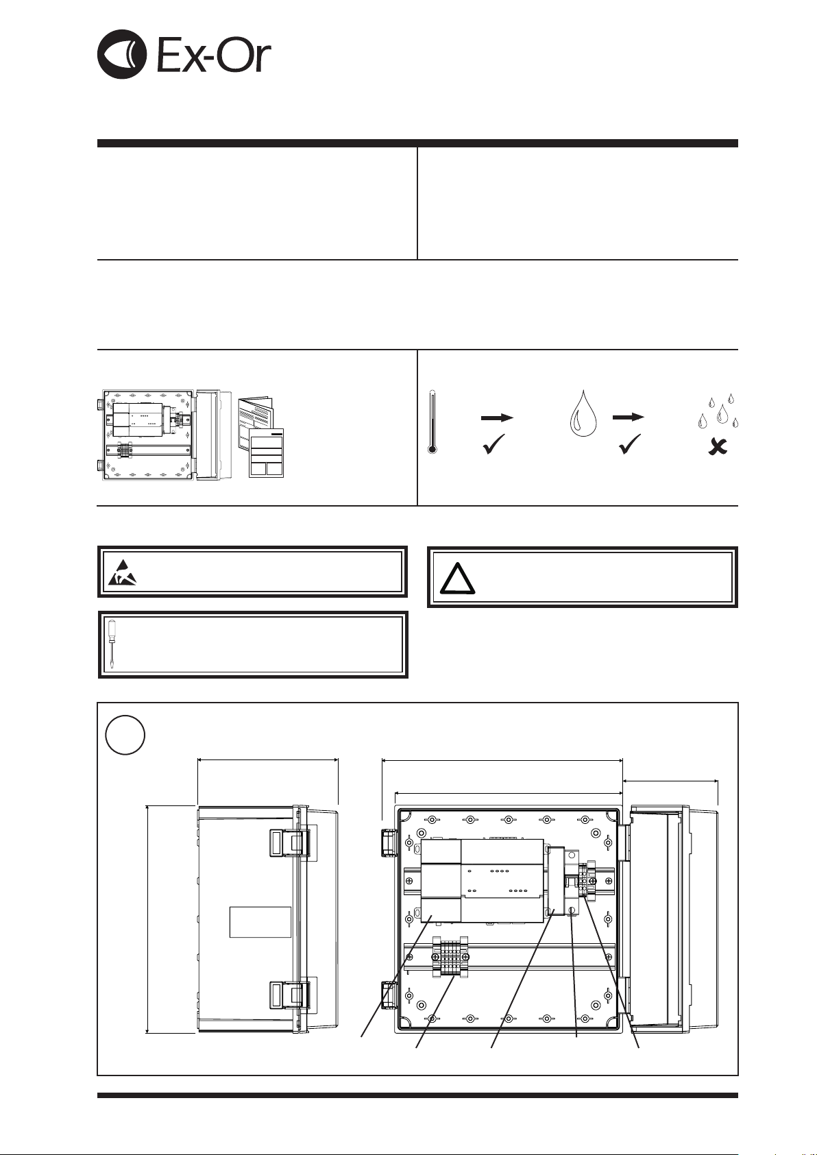
1 Box Contents .................................................................1
2 Storing ...........................................................................1
3 Installation .....................................................................1
4 Field Maintenance .........................................................4
5 Disposal .........................................................................4
1 BOX CONTENTS 2 STORING
Unit with door open
MLSUC500 / 1250
Installation
Enclosure
Instructions - Mounting
(32340084-001)
and enclosure
mounting instructions.
-40°C
+85°C
3 INSTALLATION
ATTE NTION : Observe precautions for handling
electrostatic sensitive devices.
It is recommended that the installation should comply
with the local electrical safety installation practices (e.g.
HSE Memorandum of Guidance on Electricity at Work
Regulations 1989, USA National Electric Code).
WARNING: Contains no serviceable parts. Do not
attempt to open the unit. Failure to comply may
cause damage to the unit.
5
95%RH
1
300 mm (11.75”)
MLSUC500 / 1250 Installation Guide 32340084-001 Rev A, 24-Aug-2018. MU1B-0638GE51 R0718A 1
185 mm (7.25”)
MLSJ8
MLS spine terminals
335 mm (13.25”)
300 mm (11.75”)
MLS circuit breaker
MLS PSU
Allow
Cover clearance
MLS power terminals
Dimensions & Clearances (including optional expansion modules)
Page 2

MLSUC500 / 1250 Installation Guide
HO
2
3 INSTALLATION (continued)
2
Mounting Requirements
-20°C
Altitude <2000m (6562’)
Pollution degree 3
+60°C
Mount MLSUC500 / 1250
5
3
95%RH
Ensure that the enclosure keeps the MLSJ8 within its
required operating temperature range (considering a 24-watt
dissipation).
Do not mount the unit:
▪ in an area with excessive moisture, corrosive fumes, or
explosive vapours.
▪ where vibration or shock is likely to occur.
▪ in a location subject to electrical noise
The MLSUC500 / 1250 can be wall mounted by xing the
supplied wall mounting lugs to the corner holes on the rear
side as described in the supplied enclosure xing instructions.
4
Alternative xing positions
in four places
Connect Power
Mains
Input
Green/Yellow
Blue
Brown
The entry for the power wiring can be made by drilling a
conduit of around 20mm at the bottom or either side of the
enclosure.
The power wiring must be terminated at the MLS power
terminals and circuit breaker and terminal blocks. The MCB
and the terminal blocks are prewired to the MLSJ8 PSU in
the f actor y.
Note: the MLS circuit breaker and MLS PSU are pre wired
to the MLSJ8.
DO NOT SWITCH ON POWER
O
I
2 MLSUC500 / 1250 Installation Guide 32340084-001 Rev A, 24-Aug-2018. MU1B-0638GE51 R0718A
Page 3

Installation Guide MLSUC500 / 1250
BA
Screen
Z
Y
BA
Screen
Z
Y
3 INSTALLATION (continued)
5
Connect Ethernet
RJ45
Standard Ethernet cable
(Cat 5e twisted pair)
maximum 100 m (109 yds)
The entry for wiring into the main enclosure can be made by
drilling a conduit of around 20mm at the bottom or either side
of the enclosure.
Default Settings IP Address Subnet Mask
PRI (L AN 1) 19 2 .1 6 8 .1.14 0 255.255.255.0
Hub / Switch
Router
RJ45
Caution: MLSUC500 / 1250 is not compatible with PoE
(Power over Ethernet) networks. Connecting to a PoE
network may cause the unit to stop functioning. In that
event, disconnect it from the network segment and powercycle the MLSUC500 / 1250.
6
Connect MLS Spine
MLSUC500 / 1250
RB2000
to further
remote
RB2000’s
The MLSUC500 / 1250 assumes the role of Bus Master on
the MLS Spine. This means that all the RB2000s should
be given consecutive, unique non-zero addresses, refer to
RB2000 documents.
The last unit at each end of the MLS spine should be
congured to terminate the two RS485 signal pairs, A-B
and Y-Z. In the case of an RB2000 being the last device this
is simply a matter of sliding the switch behind the address
setting switches to the ON position.
The entry for wiring into the main enclosure can be made by
drilling a conduit of around 20mm at the bottom or either side
of the enclosure.
Note: The spine connections from the MLSJ8 are prewired to
the terminal blocks.
≤ 32 devices
RS-485
MLSUC500 / 1250 Installation Guide 32340084-001 Rev A, 24-Aug-2018. MU1B-0638GE51 R0718A 3
Page 4

MLSUC500 / 1250 Installation Guide
!
Normal operation indication
Fault indications
or
STAT BEAT
3 INSTALLATION (continued)
7
8
Switch On Power to MLSUC500 / 1250
O
I
Check STAT & BEAT Indicators
30s
STAT
BE AT
STAT Contact technical support.
BE AT
Contact technical support.
9
Congure MLSUC500 / 1250
MLSUC500 / 1250 Conguration Manual (W6003)
The following information will be useful;
• RB2000 locations.
• Zones and their respective RB2000 address must be clearly marked.
• The Ballast type and timeout period should also be listed.
• Zone identities. Such as room names or numbers.
• LCM locations.
• Emergency Ballasts.
Some of this information may only be available from those who commission the MLS
lighting control system which may or may not be an Ex-Or commissioning Engineer.
5 FIELD MAINTENANCE
MLSUC500 / 1250 requires no routine maintenance.
WARNING: Contains no serviceable parts. Do not
attempt to open the unit. Failure to comply may
cause damage to the unit.
6 DISPOSAL
WEEE Directive:
At the end of their useful life the packaging and
product should be disposed of by a suitable
recycling centre.
Do not dispose of with normal household waste.
Do not burn.
© 2018 Novar ED&S Limited.
Honeywell Ex-Or reserves the right to revise this publication from time to time and make changes to the content hereof without obligation to notify any
person of such revisions or changes.
Honeywell Ex-Or
St. Mark’s Court, North Street, Horsham, West Sussex, RH12 1BW, UK. Tel:+44 (0)1403 211888 Fax:+44 (0)1403 241608 www.ex-or.com
4 MLSUC500 / 1250 Installation Guide 32340084-001 Rev A, 24-Aug-2018. MU1B-0638GE51 R0718A
 Loading...