

Ex-Or MLS2500D, MLS2500DF, MLS2500DWL, MLS2500DWLF, MLS2500DALI Installation Instructions
...Page 1
MLS2500D / MLS2500DF
MLS2500DWL* / MLS2500DWLF*
MLS2500DALI / ML2500DALIF
MLS2500DALIWL* /
MLS2500DALIWLF*
Digital Mid Range Series Detector
MLS2500D(WL)
MLS2500DALI(WL)
MLS2500D(WL)F
MLS2500DALI(WL)F
Installation and Commissioning
Instructions
Note: QuickSet Pro required for commissioning
Page 2
Digital Mid Range Series Detector
Fixing
Only suitably qualified personnel should install this equipment.
1. This is an extremely sensitive movement detector; it is essential therefore that it be installed on a rigid
surface that will not itself be subject to any movement or vibration.
2. Before isolating the circuits to be switched, check that all lighting is fully operational and that there is no
moving equipment or machinery within the monitored area which may cause nuisance switching.
3. Position the detector where it has a good forward “view” of the area to be controlled. Ideal mounting
location is normally in a corner by the entrance or at one end of a corridor at a height of 2.5 to 4m. Do not
mount within 25cm of a fluorescent fitting.
Please note that this product uses microwave technology to detect occupancy and is not recommended
for applications where there are large areas of metal, e.g. metal ceiling or panelling, as unpredictable
sensitivity may result.
Also, microwave presence detection is not completely attenuated by materials such as plasterboard,
wood and glass, so the possibility of unwanted presence detection through office partitions should be
considered when determining detector positioning and sensitivity settings within the intended application.
4a. MLS2500D - Surface version
Separate the detector from its back-box by loosening the locking screw so that approximately 3mm of
thread is visible and then twisting the detector off the back-box. Note the arrow symbol moulded into the
bottom of the back-box. The fixing holes allow for mounting on a BESA box or direct to a rigid surface.
Secure the back-box firmly to a rigid surface so that the arrow points into the controlled area.
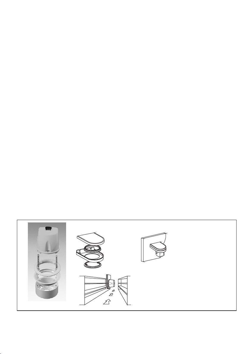
4b. MLS2500DF- Semi-flush version
Use a hole saw to drill a 76mm hole into the ceiling tile. The flush ring is designed to clamp the tile between
its two halves. Loosen the locking screw so that approximately 3mm of thread is visible and remove the
bottom half of the flush ring. With the detector in the ceiling, pointing towards the area to be controlled, fit
the bottom half of the flush ring to the assembly. Depending on the thickness of the ceiling tile, screws
longer than those supplied may be required to hold the two halves of the flush ring together.
It is recommended that Mid Range detectors be ceiling mounted. Where this is not possible, the wall-mounting
kit (WMK - see below) must be used.
Exploded view of detector
for fixing into ceiling tiles.
WMK Wall-mounting Kit
(Supplied assembled)
Vertical installation
Use this method of mounting for racking aisle
applications and where adjustment in the
vertical plane will give improved control over
the precise point of entry detection.
2
Horizontal installation
For general applications where
ceiling mounting is not
convenient and wide angle
coverage in the horizontal plane
is desirable. The WMK can be
screwed to a hard surface or the
lid of a conduit stop-end box.
Page 3
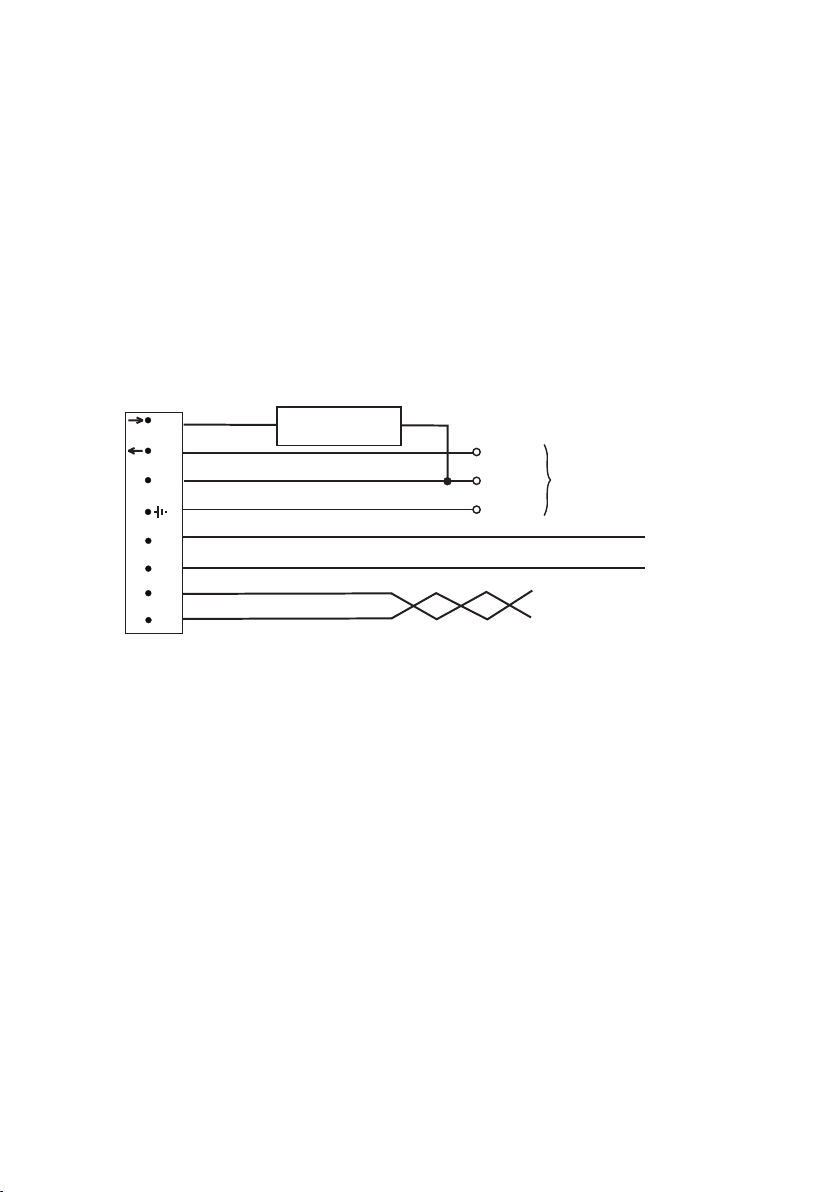
Electrical Connections
Detectors should be connected in accordance with the diagram below.
Digital Mid Range Detectors are designed to control up to 25 DSI or DALI ballasts, a switched load of up to
10 Amps or a combination of the two. When controlling DSI or DALI ballasts the ballast types must not be
mixed. The DSI or DALI input terminals on the ballasts should be connected in parallel with each other and to
the Polarity-Free Digital Output terminals of the detector. Each DSI or DALI luminaire is controlled completely
by its digital input and therefore would normally have a permanent power supply. Turning the power off to
some lights within a control circuit will not affect the operation of those lights that remain powered and under
the control of the detector.
When switching via the relay output, multiple MLS2500Ds' relay outputs may be connected in parallel
provided the controlled load does not exceed 10 Amps. If digital ballasts are also being controlled, the digital
outputs from different detectors must never be connected one to another, even if they are of the same type.
Live Out
Live In
Neutral
Earth
D1
D2
MLS 1
MLS 2
8
SW
L
7
L
6
N
5
4
D
3
D
(Digital Out)
M
MLS 2-core Bus Cable Do NOT connect to Mains
1 2
M
(MLS Bus)
SWITCHED LOAD
10 Amps Maximum
Live
Neutral
Mains
Supply
Earth
Digital Dimming Signal Pair to Ballasts
Note: A means of disconnection must be incorporated into the fixed wiring in accordance with the current
wiring regulations.
Always check product label before wiring
3
Page 4

Commissioning
The units are supplied with the factory default settings, shown below, which render commissioning, apart from
zoning, unnecessary in many applications. To allocate to zone(s), effected via the MLS Bus signals, and
make use of the programmable settings, an infrared commissioning tool (QuickSet Pro) is required.
A ten-second time delay is selectable to aid commissioning.
Sensitivity to Movement
While the factory settings will be correct for many applications, the sensitivity can be adjusted if required.
ON Sensitivity: This sets the detector’s range when the lights are ON. Choose setting from 1-100 where 1 is
lowest and 100 is maximum. (Note: Choose the lowest level possible to give adequate detection.)
OFF Sensitivity: This sets the detector’s range when the lights are OFF. Choose % setting from 10% to
100% where 10% = 10% of ON Sensitivity and 100% = same as ON Sensitivity. This is an approximation and
should be tested on site during commissioning.
Like all programmable parameters, the sensitivity settings will be retained in the event of a power failure and
can be re-programmed any number of times.
Factory Default Settings
These are the settings to which the units have been programmed before they leave the factory.
Parameter
Power Up
Response
Off Delay
On Sensitivity
Off Sensitivity
Bus Connect
1st Zone
2nd Zone
3rd Zone
4th Zone
Corridor 1 Begin/End
Corridor 2 Begin/End
Global 1 Rx
Global 2 Rx
Manual I/P
Start Lamps
Entry Scene
Lamp Max
Dimming
Fade to Off
When Vacant
Bright-Out
Pcell Rly
Set-Point Low
Set-Point High
Options
On/Off
Auto, Manual/Bus, Manual only
1min-96hrs, 10 secs (walk test), Disabled
0-100
100-10% in 10% increments
Yes/No
Address 1-100, -- (no zone), Comn 1-3
Address 1-100, --, Comn 1-3
Address 1-100, --, Comn 1-3
Address 1-100, --, Comn 1-3
00-100, --, Building
00-100, --, Building
Yes/No
Yes/No
Local/Share
Max/Min
Scenes 1-6
100-10%
Regulate 100-50%
No/Yes
Off, 9 Exit Scenes (3 options x 3 durations)
No/Yes
Disabled/Passive/Active
0-1023
0-1023
Default
Setting
ON
AUTO
20 min
19
100%
Yes
--
--
--
--
--
-NO
NO
LOCA L
MAX
01
100%
100%
NO
OFF
NO
Disabled
766
1022
Options
Each of these settings
can be re-programmed,
if desired, by use of the
infrared programming
tool QuickSet Pro.
- Manual Input is only
available via the
Wireless OneSwitch
facility of the
MLS2500DWL(F) and
MLS2500DALIWL(F).
See Application Note
AN4021 for further
information
4
Page 5

Photocell Control
i) Regulating Photocell
Regulating photocell control tries to maintain a constant level of total illumination in the space controlled by
dimming and brightening the controlled luminaires to compensate for changes in illumination from other
sources.
With the photocell configured as DISABLED the Regulating Control module is influenced only by the
BRIGHT-OUT setting. BRIGHT-OUT = YES allows it to hold-off the lights at the start of occupancy if natural
light already exceeds SET-POINT LOW and to extinguish the lights during occupancy if total light, after the
controlled luminaires have been dimmed to minimum, exceeds SET-POINT HIGH continuously for a period
equal to the OFF DELAY . The lighting is restored immediately if the illumination level subsequently drops
below SET-POINT LOW.
If the photocell is configured for ACTIVE or PASSIVE control of the relay switched load, then the Regulating
Control module adopts the decision made by the Switching Control module in the case of turn-on inhibit on
entry, but still obeys the BRIGHT-OUT YES/NO setting with regard to turn-off during occupancy.
ii) Switching Photocell (PHOTOCELL: ACTIVE or PASSIVE)
Both ACTIVE or PASSIVE modes hold off the controlled lighting on entry when natural light is sufficient,
i.e. SET-POINT LOW is exceeded, but only ACTIVE mode will extinguish the lighting if natural light increases
sufficiently during occupancy, i.e. SET-POINT HIGH is exceeded continuously for a period equal to OFF
DELAY. The lighting is restored immediately if the illumination level subsequently drops below SET-POINT
LOW.
iii) Photocell DISABLED
If the photocell is configured as DISABLED for relay Switching Control it will have no effect on the control of
that load, which will be ON continuously during periods of occupancy unless commanded OFF via manual
switch or infrared control. The photocell readings are still available for use by the Regulating Control module
while in this mode.
Programming the Photocell Set-points
The parameters SET-POINT LOW and SET-POINT HIGH programme the detector’s photocell response.
The SET-POINTS can be manually programmed as numbers between 1 (darkest) and 1023 (brightest). This
number is not scaled to correlate with ‘lux’ measurements made using a light meter, but nevertheless is a true
representation of the light level perceived by the detector. To assist with finding the appropriate SET-POINT
settings, the light level currently perceived by the photocell can be viewed on the QuickSet Pro screen briefly,
following a download operation. The number represents the light level read immediately before the download
took place.
Tip: Turn the lights off with the QuickSet Pro (UTILITIES / LIGHTSPOT/MLS/LCM / IR REMOTE / HC5)
to measure the perceived light level with no contribution from the controlled lighting.
Alternatively the SET-POINTS can be configured semi-automatically;
i) The Primary Interest is the Regulating Control Output.
With the photocell configured as DISABLED:-
Using QuickSet Pro (UTILITIES / LIGHTSPOT/MLS/LCM / SET LIGHT LEVEL) or HC5A (+,- Scene 1)
set the required light output from the controlled luminaires and then press and hold OK (QuickSet Pro) or
Scene 1 (HC5A) until the controlled lights "blink" to indicate that a new SET-POINT LOW has been stored
and a calculated SET-POINT HIGH has also been inserted. Using the QuickSet Pro the photocell can now
be re-configured as ACTIVE or PASSIVE if required.
5
Page 6

ii) The Primary Interest is the Switching Control Output
With the photocell configured as ACTIVE or PASSIVE:-
1) If the lights are not already on, switch them on manually by pressing ‘UTILITIES / LIGHTSPOT/MLS/LCM
/ IR-REMOTE / HC5 / Luminaire+ / OK’ (QuickSet Pro) or "+" (HC5A). Fluorescent lights do not reach full
output until up to 15 minutes after being switched on, so ensure that the lights are fully warmed up before
continuing.
2) Wait until the time of day when the natural light level is at the point below which you would want the lights to
be on, and above which you would not want the lights to be on.
3) Start the internal self-programming mechanism by pressing ‘UTILITIES / LIGHTSPOT/MLS/LCM / SET
LIGHT LEVEL / OK’ (QuickSet Pro) or Scene 1 (HC5A). The detector takes a photocell reading, adds a small
amount and stores the value in SET-POINT HIGH. Then it turns the lights off, makes another measurement
and stores the value in SET-POINT LOW. The lights now switch on again to acknowledge a successful
programming operation.
The two switching thresholds have now been set, and the difference between them is equal to slightly more
than the contribution made by the electric lighting. This is the perfect amount of hysteresis to ensure that the
lights will not oscillate.
6
Page 7

Important Additional Notes
1. All terminals on this product are provided for final connections. It is not intended that the product be used as a
junction box for looping cables.
2. Although nominally 12V, the dimming output is not SELV and therefore should be treated with the same respect as
mains with regard to wiring practice.
3. Take care when choosing a location for this equipment since this type of device is capable of detecting large
moving metal objects well beyond the normal range at which it is sensitive to human targets.
4. Please note that, although configurable as a regulating photocell, [closed-loop dimming according to daylight],
due to the probable corner-of-room location where there will be excessive influence by daylight reflected from the
walls, this product is not intended to achieve precise light level regulation measured on the working plane.
5. This equipment switches lights no more frequently than would a responsible human occupant. However,
manufacturers of some lighting types (e.g. ‘2D’ luminaires) may specify a maximum number of switching cycles in
order to achieve a predicted lamp life. Please check with the manufacturer of the luminaires to ensure that they
are compatible with automatic controls in this respect.
7
Page 8

Technical Data
MLS CABLE: 1.5mm unscreened twisted-pair (applicable when detector used as part of a full MLS Digital
2
Managed Lighting System): see Application Note AN4001
OPERATING VOLTAGE: 230V ~ 50Hz (UK & Europe)
SWITCH CAPACITY: 10 Amps max any lighting load except incandescent lamps: 1500W max (at 230V~)
MAXIMUM RECOMMENDED LOAD (DSI/DALI): 25 Ballasts
MAXIMUM RECOMMENDED MOUNTING HEIGHT: 3.5m
RANGE: Adjustable up to 20m
OFF DELAY: 1 min - 96 hours plus 10-second walk-test mode
PHOTOCELL: Passive/Active/Regulating adjustable 50-5000 lux
MATERIAL: Flame retardant PC/ABS
COLOUR: White RAL9010
WEIGHT: 180g (flush version), 160g (surface version)
IP RATING: 4X
OPERATING TEMPERATURE: 0 C to 40 C
o o
Contact Ex-Or Technical Helpline on 01942 719229 for guidance on installation and commissioning.
Honeywell Ex-Or
St. Marks Court, North Street,
Horsham, West Sussex RH12 1BW, UK
Tel: + 44 (0)1942 719229
Fax: +44 (0)1942 272767
Email: technicalsales.ex-or@honeywell.com
www.ex-or.com
At the end of their useful life
the packaging and product
should be disposed of via a
suitable recycling centre.
Do not dispose of with normal
household waste.
Do not burn.
W4364E
 Loading...