

Ex-Or MLS2421DF, MLS2421DALIF, MLS2421DSM, MLS2421DALISM Ex-Or MLS2421DALIF Presence Detector Installation Instructions

MLS2421DSM
MLS2421DALISM
Installation and Commissioning
Instructions
Note: HP2000 required for commissioning
MLS2421DF & MLS2421DSM for DSI ballasts
MLS2421DALIF & MLS2421DALISM for DALI ballasts
Digital Gold Series Detector
with regulating photocell
MLS2421DF
MLS2421DALIF
2
Digital Gold Series Detector with Regulating Photocell
Please note that UltraLite versions of these detectors (suffix CWL7) do not offer MLS functionality
and cannot be connected using MLS cable.
Only suitably qualified personnel should install this equipment.
The Digital Gold is a high-performance, communicating presence detector which can be used as part of a full
Ex-Or MLS Digital Managed Lighting System or as a stand-alone unit. The MLS2421D detector is equipped
with a regulating photocell to control digital DSI or DALI ballasts (when using the detector’s Digital Output) and
a volt-free output for control of non-dimmable lighting loads. Digital Gold incorporates Ex-Or’s OneSwitch
Dimming, local manual operation of any controlled lighting load.
Location
This is an extremely sensitive movement detector; it is essential therefore that it be installed on a rigid surface
that will not itself be subject to movement or vibration.
Please note that this detector is not recommended for applications where there are large surface areas of
metal, e.g. metal ceiling or floor tiles, as unpredictable sensitivity may result.
The units are graded according to four variations in operating frequency. Each type can be identified by
different colour-coding on the detector label and carton. For reliable operation it is essential that units of the
same colour code do not occupy adjacent positions in open-plan areas or in adjoining rooms (see below).
Yellow
Blue
Red
Green
Red
Green
Yellow
YellowBlue
Red
Green
YellowBlue
Yellow
Green
Green
Yellow
Green
Yellow
YellowBlue
Red
Green
Red
Green
YellowBlue
Red
Green
YellowBlue
Blue
Red
Red
Blue
Red
Blue
Yellow
Blue
Red
Green
Red
Green
Yellow
YellowBlue
Red
Green
YellowBlue
Yellow
Green
Green
Yellow
Green
Yellow
YellowBlue
Red
Green
Red
Green
YellowBlue
Red
Green
YellowBlue
Blue
Red
Red
Blue
Red
Blue
Note: Should you need to order additional detectors for an existing installation
and need specific colour-coded detectors, please add the following suffixes to
the part number: Y = Yellow, B= Blue, G= Green, R = Red. (There is normally
no need to specify the colour codes as orders are dispatched with a suitable
colour-code mix.)
Fixing
MLS2421DSM/DALISM - The housing may be secured to a hard surface or a BESA box. The unit fits into the
housing with a simple bayonet action.
MLS2421DF/DALIF - Depth required behind ceiling: 62mm from front flange plus an allowance for the
minimum bend radius of the cable. Sinking box fits into a 89mm diameter hole in ceiling tile or plasterboard
ceiling. To avoid damage to ceiling tile, do not overtighten. No access above the ceiling is necessary.
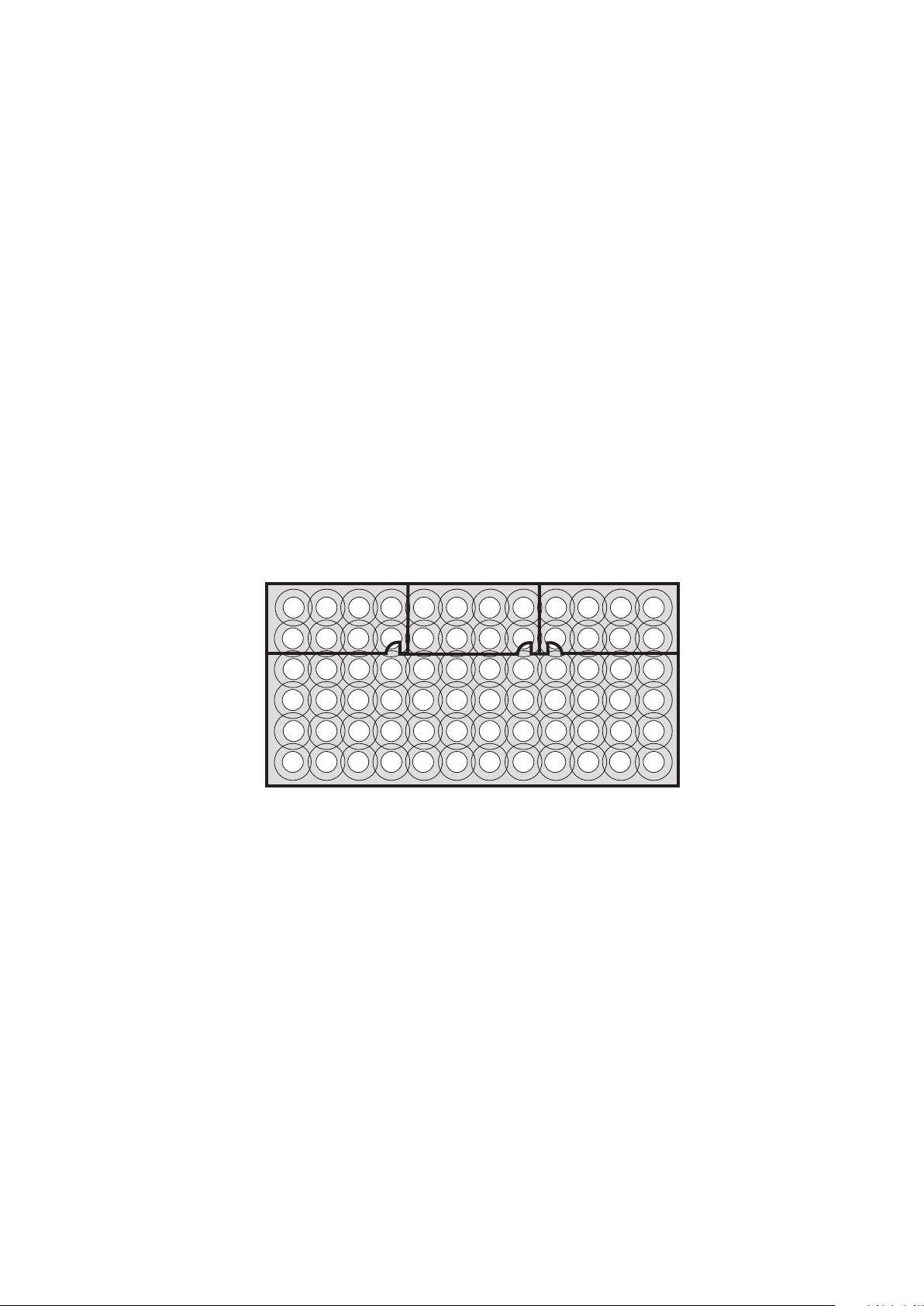
Please note:Do not position this product on a pitch narrower than 5m.
Do not mount within 0.25m of a luminaire.

3
Electrical Connections
These Digital Gold detectors should be connected in accordance with the diagrams below. Both the Digital Output
and MLS connections are polarity-free however other MLS products require that polarity be maintained. The MLS
cable should be mains-rated, unscreened, twisted pair of at least 1.5mm CSA. For further information please refer
to Wiring Application Guide AN4001. Please note that UltraLite versions of these detectors (suffix CWL7) do
not offer MLS functionality and cannot be connected using MLS cable.
These detectors are designed to control up to 25 DSI or DALI luminaires, a switched load of up to 6 Amps or a
combination of the two. When controlling DSI or DALI ballasts the ballast type must not be mixed. The DSI or DALI
input terminals on the ballasts should be connected in parallel with each other and to the Polarity-Free Digital
Output terminals on the rear of the detector. Each DSI or DALI luminaire is controlled completely by its digital input
and therefore would normally have a permanent power supply. Turning the power off to some lights within a control
circuit will not have affect the operation of those lights that remain powered up and under the control of the detector.
When switching via the volt-free output multiple detectors may be connected in parallel provided the controlled
load does not exceed 6 Amps. If digital ballasts are also being controlled the digital outputs from each detector
must not be mixed even if they are of the same type.
W4178M
Wiring Examples
Digital
Output
MLS
BUS
These Connections are Polarity-Free
1 2 1 2
Using OneSwitch, MLS*, Switched
and Digital Outputs
N
E
L
Permanent
or switched
supply
VOLTFREE
OUTPUT
LIVE
NEUTRAL
EARTH
LOAD
(MAX 6 AMPS)
ONESWITCH
DIMMING
Digital output
MLS Bus Connection
(Some MLS devices require
that polarity be maintained)
Momentary
push-to-make
switch
Please note that the Earth terminal has no internal connection
and is used for termination only.
Digital
Output
MLS
BUS
These Connections are Polarity-Free
1 2 1 2
Using Switched Output and MLS*
N
E
L
Permanent
or switched
supply
VOLTFREE
OUTPUT
LIVE
NEUTRAL
EARTH
LOAD
(MAX 6 AMPS)
ONESWITCH
DIMMING
MLS Bus Connection
(Some MLS devices require
that polarity be maintained)
NC
NC
Please note that the Earth terminal has no internal connection
and is used for termination only.
VOLTFREE
OUTPUT
NEUTRAL
LIVE IN
EARTH
ONE
SWITCH
NC
VOLTFREE
OUTPUT
NEUTRAL
LIVE IN
EARTH
ONE
SWITCH
NC
LOAD
(Max 6 Amps)
E
L
N
Permanent
or switched
supply
2 x MLS2421D In Parallel, using
Switched Output only
Any connection not shown is NO CONNECTION
Relay outputs may be connected together in
parallel to cover larger areas, however the
total load on all combined relay outputs
must not exceed 6 Amps.
* UltraLite-version detectors (suffix CWL7)
do not offer MLS functionality and cannot
be connected using MLS cable.
* UltraLite-version detectors (suffix CWL7)
do not offer MLS functionality and cannot
be connected using MLS cable.

4
Commissioning
The units are supplied with the factory default settings shown below which render commissioning
unnecessary in many applications. To make use of the programmable settings, an infrared commissioning
tool is required (HP2000). A ten-second time delay is selectable to aid commissioning.
Sensitivity to Movement
While the factory settings will be correct for many applications, the sensitivity can be adjusted if required.
ON Sensitivity: This sets the detector’s range when the lights are ON. Choose setting from 1-100 where 1 is
lowest and 100 is maximum. (Note: Choose the lowest level possible to give adequate detection.)
OFF Sensitivity: This sets the detector’s range when the lights are OFF. Choose % setting from 10% to
100% where 10% = 10% of ON Sensitivity and 100% = same as ON Sensitivity. This is an approximation and
should be tested on site during commissioning.
Like all programmable parameters, the sensitivity settings will be retained in the event of a power failure and
can be re-programmed any number of times.
Factory Default Settings
These are the settings to which the units have been programmed before they leave the factory.
Parameter
Power up
Response
Off Delay
On Sensitivity
Off Sensitivity
Bus Connect
1st Zone
2nd Zone
3rd Zone
4th Zone
Corridor 1 Begin/End
Corridor 2 Begin/End
Global 1 Rx
Global 2 Rx
Manual I/P
Start Lamps
Entry Scene
Lamp Max
Dimming
Fade to Off
When Vacant
Bright-Out
Pcell Rly
Set-Point Low
Set-Point High
Default
Setting
ON
AUTO
20 min
19
100%
YES
--
--
--
--
--
-NO
NO
LOCAL
MAX
01
100%
Reg 100%
NO
OFF
NO
Disabled
766
1022
Options
On/Off
Auto, Manual/Bus, Manual only
1min-96hrs, 10 secs (walk test), Disabled
0-100
100%-10% in 10% increments
Yes/No
Address 1-100, -- (no zone), Comn 1-3
Address 1-100, -- (no zone), Comn 1-3
Address 1-100, -- (no zone), Comn 1-3
Address 1-100, -- (no zone), Comn 1-3
0-100, --, Building
0-100, --, Building
Yes/No
Yes/No
Local/Share
Max/Min
Scenes 1-6
100%-10%
Reg 100%-50%
Yes/No
Off, 9 Exit Scenes (3 options x 3 durations)
Yes/No
Disabled/Passive/Active
0-1023
0-1023
Options
Each of these
settings can be
re-programmed,
if desired, by use of
the infrared
programming
tool HP2000.

Photocell Control
i) Regulating Photocell
Regulating photocell control tries to maintain a constant level of total illumination in the space controlled by
dimming and brightening the controlled luminaires to compensate for changes in illumination from other
sources.
With the photocell configured as DISABLED the Regulating Control module is influenced only by the BRIGHTOUT setting. BRIGHT-OUT = YES allows it to hold-off the lights at the start of occupancy if natural light already
exceeds SET-POINT LOW and to extinguish the lights during occupancy if total light, after the controlled
luminaires have been dimmed to minimum, exceeds SET-POINT HIGH continuously for a period equal to the
OFF DELAY . The lighting is restored immediately if the illumination level subsequently drops below SETPOINT LOW.
If the photocell is configured for ACTIVE or PASSIVE control of the relay switched load then the Regulating
Control module adopts the decision made by the Switching Control module in the case of turn-on inhibit on
entry, but still obeys the BRIGHT-OUT YES/NO setting with regard to turn-off during occupancy.
ii) Switching Photocell (PHOTOCELL: ACTIVE or PASSIVE)
Both ACTIVE or PASSIVE modes hold off the controlled lighting on entry when natural light is sufficient, i.e.
SET-POINT LOW is exceeded, but only ACTIVE mode will extinguish the lighting if natural light increases
sufficiently during occupancy, i.e. SET-POINT HIGH is exceeded continuously for a period equal to OFF
DELAY. The lighting is restored immediately if the illumination level subsequently drops below SET-POINT
LOW.
iii) Photocell DISABLED
If the photocell is configured as DISABLED for relay Switching Control it will have no effect on the control of that
load, which will be ON continuously during periods of occupancy unless commanded OFF via manual switch
or infrared control. The photocell readings are still available for use by the Regulating Control module while in
this mode.
Programming the Photocell Set-points
The parameters SET-POINT LOW and SET-POINT HIGH programme the detector’s photocell response The
SET-POINTS can be manually programmed as numbers between 1 (darkest) and 1023 (brightest). This
number is not scaled to correlate with ‘lux’ measurements made using a light meter, but nevertheless is a true
representation of the light level perceived by the detector. To assist with finding the appropriate SET-POINT
settings, the light level currently perceived by the photocell can be viewed on the HP2000 screen briefly,
following a download operation. The number represents the light level read immediately before the download
took place.
Tip: Turn the lights off (HP2000 UTILITIES/USER-REMOTE) to measure the perceived light level with no
contribution from the controlled lighting.
Alternatively the SET-POINTs can be configured semi-automatically;
i) The Primary Interest is the Regulating Control Output.
With the photocell configured as DISABLED:-
Using HP2000 (UTILITIES / SET LIGHT LEVEL) or HC5 (+,- Scene 1) set the required light output from the
controlled luminaires and then press and hold OK (HP2000) or Scene 1 (HC5) until the controlled lights
"blink" to indicate that a new SET-POINT LOW has been stored and a calculated SET-POINT HIGH has also
been inserted. Using the HP2000 the photocell can now be re-configured as ACTIVE or PASSIVE if required.
5
W4178M

ii) The Primary Interest is the Switching Control Output
With the photocell configured as ACTIVE or PASSIVE:-
1) If the lights are not already on, switch them on manually by pressing ‘UTILITIES/USERREMOTE/Luminaire+/OK’ (HP2000) or "+" (HC5). Fluorescent lights do not reach full output until up to 15
minutes after being switched on, so ensure that the lights are fully warmed up before continuing.
2) Wait until the time of day when the natural light level is at the point below which you would want the lights
to be on, and above which you would not want the lights to be on.
3) Start the internal self-programming mechanism by pressing ‘UTILITIES/SET LIGHT LEVEL/OK’
(HP2000) or Scene 1 (HC5). The detector takes a photocell reading, adds a small amount and stores the
value in SET-POINT HIGH. Then it turns the lights off, makes another measurement and stores the value
in SET-POINT LOW. The lights now switch on again to acknowledge a successful programming
operation.
The two switching thresholds have now been set, and the difference between them is equal to slightly more
than the contribution made by the electric lighting. This is the perfect amount of hysteresis to ensure that the
lights will not oscillate.
OneSwitch
OneSwitch Dimming affords local control to the end-user whereby a simple, momentary, push-to-make wall
switch can be used to raise or lower the lighting level or toggle the output of the unit ON or OFF. A short press
(less than 1 second) toggles all outputs from both OFF to both ON or from either ON to both OFF. A long press
will ramp the digital output either up or down with no effect on the volt-free output. If the output prior to pressing
the switch is above 90% the output will ramp down; if below 90% it will ramp up. If the latest press and the
current press are within 5 seconds of each other it will ramp in the opposite direction.
6
User Overrides
The end-user can configure a number of lighting scenes that can be recalled using a hand-held override. With
an HC5 hand-held controller lighting can be overridden OFF or ON, or a set level can be chosen, affecting
either the controlled group or, with an MLS system, the whole zone. Regulating and switched loads can be
adjusted independently through a combination of OneSwitch Dimming and the HC5.

7
Important Additional Notes
1. All terminals on this product are provided for final connections. It is not intended that the product be used as a
junction box for looping cables.
2. A means for disconnection must be incorporated in the fixed wiring in accordance with the current wiring
regulations.
3. Although nominally 12V, the dimming output is not SELV and therefore should be treated with the same respect as
mains with regard to wiring practice. The 0V line of the dimming output is almost at Neutral potential.
4. The dimming control output should be connected only to the control input of the ballasts - never to other detectors.
5. Due to the fact that the photocell is on the ceiling looking down, it is not possible for measurements made with a lux
meter on the working plane to remain constant when daylight illuminates the ceiling and the working plane to a
differing extent. Therefore, products of this type should be regarded as capable of maintaining an
APPROXIMATE light level only.
6. This equipment switches lights no more frequently than would a responsible human occupant. However,
manufacturers of some lighting types (e.g. ‘2D’ luminaires) may specify a maximum number of switching cycles in
order to achieve a predicted lamp life. Please check with the manufacturer of the luminaires to ensure that they
are compatible with automatic controls in this respect.
7. The detectors are extremely sensitive to movement; they must be mounted on a solid surface which has no
movement whatsoever.
W4178M

Ex-Or
Novar ED&S Limited
Haydock Lane, Haydock, Merseyside WA11 9UJ
Tel: +44 (0)1942 719229
Fax: +44 (0)1942 508753
Email: technicalsales.ex-or@honeywell.com
www.ex-or.com
At the end of their useful life
the packaging and product
should be disposed of via a
suitable recycling centre.
Do not dispose of with normal
household waste.
Do not burn.
Dimensions
MLS2421DF/DALIF MLS2421DSM/DALISM
100mm
Flange:
15mm deep
100mm
62mm deep
behind ceiling
62mm
deep
Technical Data
2
MLS CABLE : 1.5mm unscreened twisted-pair (applicable when detector is used as part of a
full MLS Digital Managed Lighting System): see Application Note AN4001
OPERATING VOLTAGE: 230V 50Hz (UK & Europe)
PRODUCT RATING AND RECOMMENDED CIRCUIT PROTECTION: 10 Amps
MAXIMUM RECOMMENDED LOAD (VOLT-FREE): 6 Amps
MAXIMUM RECOMMENDED LOAD (DSI/DALI): 25 Ballasts
MAXIMUM RECOMMENDED MOUNTING HEIGHT: 3.0m
RANGE: Approx 7m dia at 2.4m ceiling height
OFF DELAY: 1 min - 96 hours plus 10-second walk-test mode
PHOTOCELL: Passive/Active/Regulating adjustable 50-5000 lux
MATERIAL: Flame retardant PC/ABS
COLOUR: White
WEIGHT: 300g
IP RATING: 2X
W4178M
 Loading...