

Ex-Or LS3043AR, LS3000D, LS3000DR, LS3243R, LS3043DR Installation Instructions And Operators Manual
...
h
Ceiling tile
thickness range
1-20mm
Ceiling tile
thickness range
1-20mm
SW
Mains supply
and Channel S1
Channel D1
Cable clamps can
be reversed to
reduce aperture
Channel D0
(QuickLink
connection)
Aspect ratio
(diameter : height)
Type
Max recommended
mounting height
Office
Mid Bay
High Bay
Switch
SW1
Switch
SW1
Digital Dimming
Luminaires Channel D1
D
D
L
N
E
DIGITAL BALLAST
Ch D0
Ch S1
Ch D1
Data & Control
Digital Dimming
IEC 60669-2-1
LS3043DR
SW L NLout
L
N
E
D
D
L
N
E
DIGITAL BALLAST
MORE
Switched Dimming
Luminaires Channel D1
+
–
L
N
E
ANALOGUE BALLAST
ANALOGUE BALLAST
L
N
E
+
–
L
N
E
MORE
Switch
SW1
Supply
Supply
Channel S1
Channel
S1
Channel D1 Channel D0
QuickLink Bus Internally Looped
To next
sensor
Low voltageLS3260
D D
Ch D0
DD
Ch D0
Loop in
Data & Control
Loop Out
DALI
DIMMING
LOAD
Supply
N
L
E
DIGITAL
DIMMING
LOAD
73mm
Ratchet Component x4
Ratchet
moulding
1
2
3
4
1
11 2 2
2
1 2
3
SWITCHING
LUMINAIRES
SWITCHING
LUMINAIRES
Removing the Terminal Cover
Remove spring
230VAC 15%
50-60Hz
+
_
Ch D0
Ch S1
Ch D1
Data & Control
Analogue Dimming
IEC 60669-2-1
LS3043AR
SW L NLout
230VAC 15%
50-60Hz
+
_
Ch D0
Ch S1
Ch D1
Data & Control
Digital Dimming
IEC 60669-2-1
IEC 60669-2-1
LS3043DR
SW L NLout
230VAC 15%
50-60Hz
+
_
Installation Instructions
LightSpot HD Dimming PIR Sensors
LS3000AR
● ● ●
LS3000D
● ●
LS3000DR
● ● ●
LS3243R
● ● ● ●
LS3043AR
● ● ● ● ●
LS3043DR
● ● ● ● ●
LS3000ARMB
● ● ●
LS3000DMB
● ●
LS3000DRMB
● ● ●
LS3000ARHB
● ● ●
LS3000DHB
● ●
LS3000DRHB
● ● ●
LS3243RMB
● ● ● ●
LS3043DRMB
● ● ● ● ●
LS3243RHB
● ● ● ●
LS3043DRHB
● ● ● ● ●
Part Number
Switching
Digital
Dimming
Analogue
Dimming
QuickLink
Office
Mid Bay
High Bay
Tilting Lens
Micro Detection -
High Sensitivity
Macro Detection -
Standard Sensitivity
3.5m
12m
16m
N/A
N/A
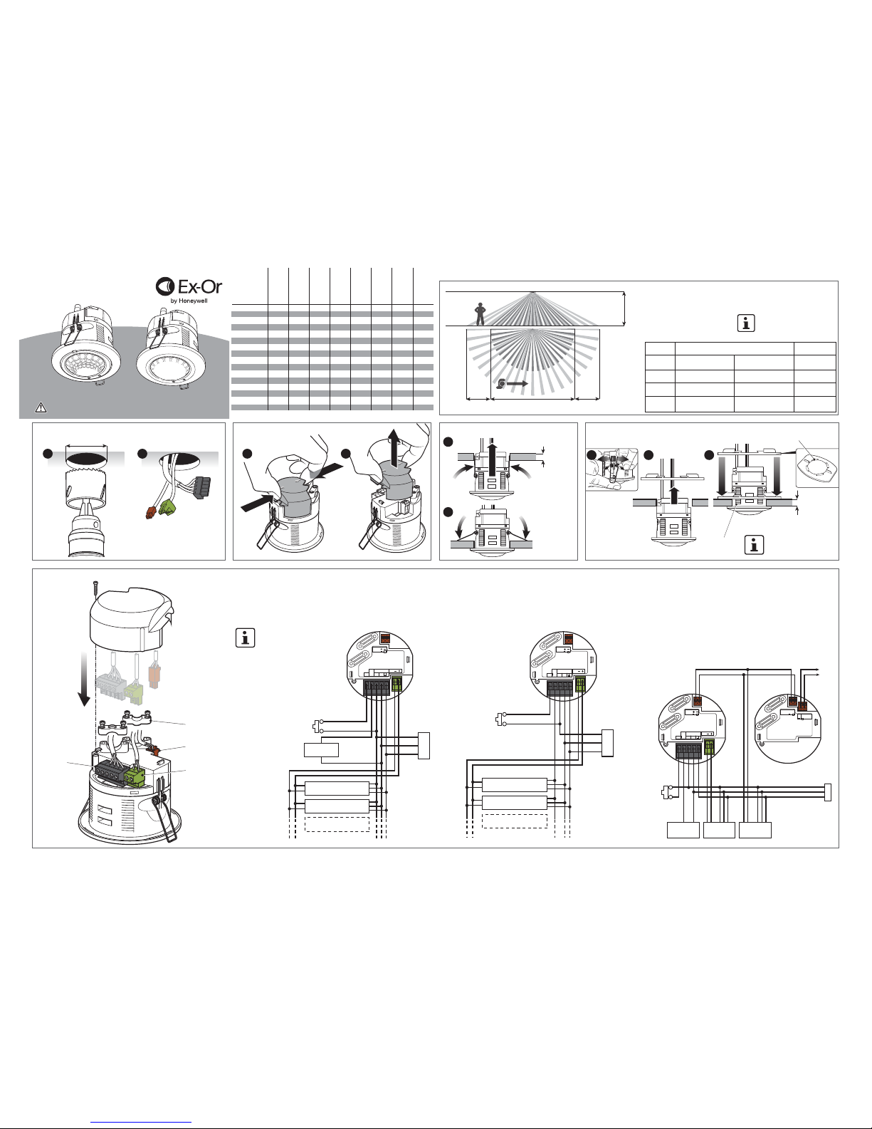
The sensor is more sensitive
to movement across the beam
compared with movement
towards the centre.
Only suitably qualified personnel should install this equipment
Add suffix F for flush mount or SM for surface mount
1.9:1
(27m diameter @14m height)
2:1
(20m diameter @10m height)
4:1
(10m diameter @2.5m height)
2.8:1
(7m diameter @ 2.5m height)
fig 1
fig 4fig 2 fig 3 fig 5
The sensor should be positioned on the ceiling in the centre of the occupied
space. This product is available in three different mounting height variants;
see fig.1 and the table below. Ensure that the maximum recommended
mounting height is not exceeded.
Avoid mounting next to an AC unit.
For additional information on
positioning please refer to Tilt
and Lock the Sensor, overleaf.
The following wiring diagrams show how to connect some of the more
fully-featured products listed in the product table above. For clarity, the wiring
for some of the lesser-featured products is not shown, but the wiring principles
are the same and equally applicable. Simply omit any sections that are not
relevant to the product being installed.
Two-Channel Application, One Channel Switching,
One Channel Digital Dimming (fig 3)
Single Channel Dimming Using Analogue
or Digital Ballasts (fig 4)
Analogue ballasts cannot be switched off from the control terminals, so it is
necessary to switch the mains power from the sensor as shown in the diagram
below. Although switching the mains power is not necessary with digital ballasts,
they may be wired this way in order to reduce the quiescent power consumption
in unoccupied areas to an absolute minimum.
Connecting Sensors together with QuickLink,
and Creation of an Additional Dimming Channel (fig 5)
The wiring diagram below shows how to connect sensors together using the
QuickLink Bus. QuickLink is a convenient way of wiring multiple sensors so
that they share information (e.g. occupancy) and are able to work in
harmony. Some sensors operate from a low voltage derived from the
QuickLink bus and therefore do not require a mains connection – this
enables fast and convenient installation. The Low Voltage Bus sensors
are not described in detail here (see QuickLink Bus Sensors Installation
Instructions for further information). It is permissible to connect up to four
sensors together in this way. No more than two mains-powered sensors
are allowed in a common connection.
NOTE:
1. Digital ballasts are normally
wired from an unswitched
supply.
2. The sensor will
automatically adjust to
control DSI or DALI
ballasts, but all ballasts
must be of the same type.
NOTE: To remove sensor
rotate Lockring and
pull up
50093557-001 / Dimming
Fixing to Ceiling – Standard Method
Installing the Sensor into Ceiling Tile
Electrical Connections
Fixing to Ceiling – Secure Lockring Method
(Available separately, please order lockring)
Positioning the Sensor
Macro
Detection
High Sensitivity Micro Detection
Macro
Detection
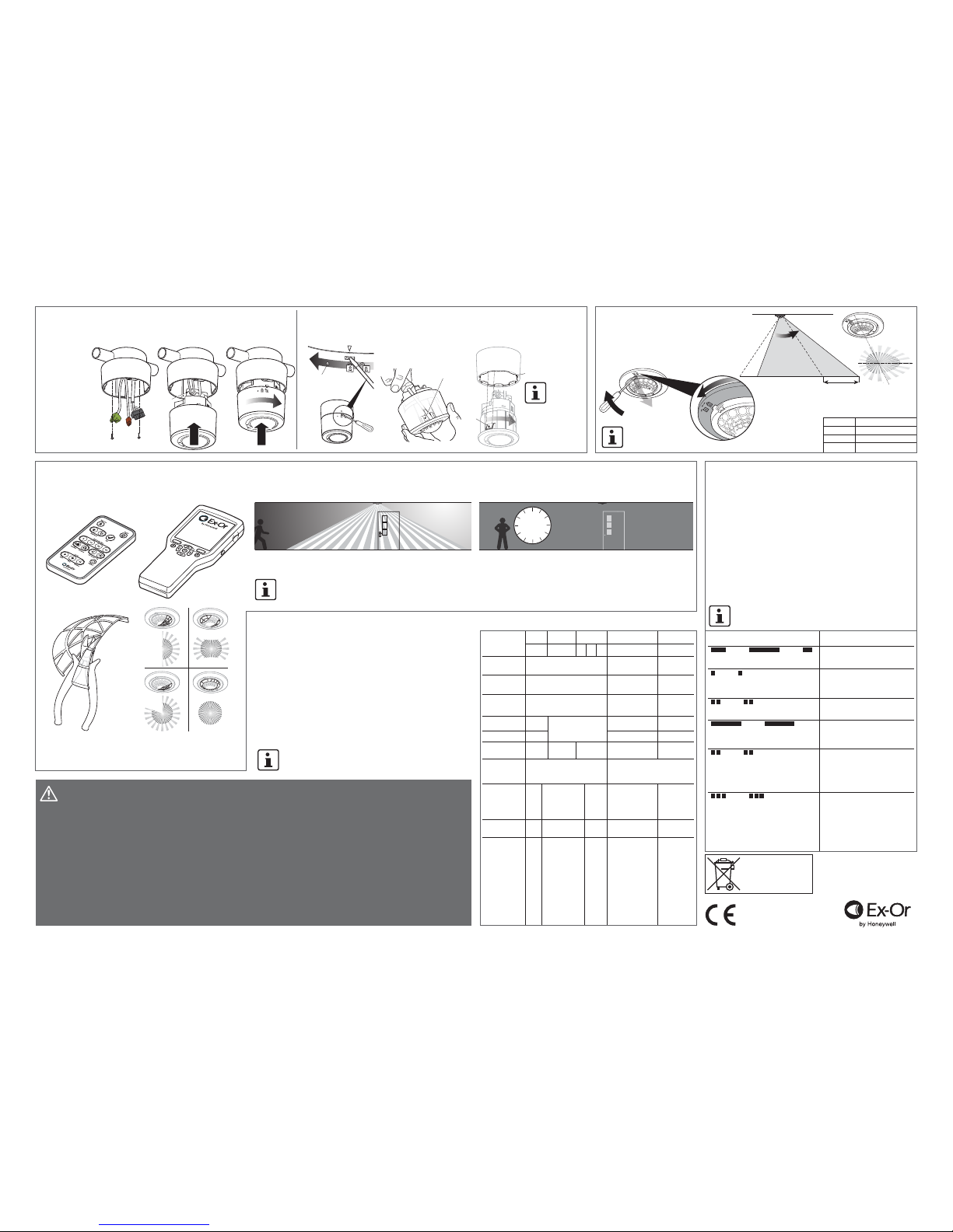
Radius extension at full tiltType
Office
Mid Bay
High Bay
increased
range
up to 67%
up to 43%
up to 42%
QuickSet
QuickSet Pro
fig 10
WalkTesting / Lens Masking
In order to verify correct installation, walk-testing is recommended.
An infrared commissioning tool will be required to put the detector(s)
into walk-test mode. Two infrared commissioning tools are available:
QuickSet and QuickSet Pro (Sold separately).
1
2
3
4
5
6
7
8
a x2
Tab
fig 7 fig 8fig 6
Technical Data
Manual
Switch
SW ChS1 Lout L N E D1- D1+ D0+ D0-
Pluggable rising cage clamp Pluggable rising Pluggable
cage clamp screwless
1 x 0.5-2.5mm sq solid or stranded
Black Blue Red
Live
Output
Power
Supply
Dimming
QuickLink and
Dimming
1 x 0.5-2.5mm sq solid
or stranded
0.75mm
sq
0.75mm sq 0.75mm sq
Derive from appropriate
wiring regulations
1 x 0.5-1.5mm sq
solid or stranded
10m 100m 100m
input output input output input and output
230VAC+/-15% 50-60Hz
Recommended circuit
protection: 16A MCB
Low Voltage – isolation 1.5kV
Negligible
N/A
N/A
N/A N/A
N/A 60mA Max 15 ballasts for
DSI, DALI and analogue
60mA
N/A N/A150mW
[QuickLink
master]
10A (maximum
inrush 80A)
Magnetic-ballasted
fluorescent,
Compact fluorescent,
Electronic-ballasted
fluorescent, LED
(maximum inrush
80A), Tungsten
lamps (Max 6A)
15 DALI digital ballasts or
15 DSI digital ballasts
*some products,
analogue ballasts
(max 15)
10 DALI digital
ballasts
QuickLink
Low Voltage
sensors (max 3)
or 1 additional
QuickLink Mains
powered Master
sensor (max 2
in network)
Ex-Or
Novar ED&S Limited
Haydock Lane, Haydock
Merseyside WA11 9UJ
Tel: +44 (0)1942 719229
Web: www.ex-or.com
Permissible load
types/connections
Maximum load
current
Power
consumption
Operating voltage
Function
Maximum length
Recommended
cable
Terminal capacity
Terminal type
Colour
Marking
fig 9
Tilt and Lock the Sensor
Some products feature the ability to tilt the sensor
(before fitting) by up to 10° in 2° increments,
in order to extend the range in one direction.
This may be useful in cases where the ideal
mounting location is not available. The incresed
range is indicated in fig 9.
Diagnostics
A number of LED indications are provided in order to help with fault-finding.
Sensors are supplied with the LEDs disabled, however they may be
enabled at the point of commissioning if required. LEDs become enabled
temporarily during walk-test. Detectable wiring faults are always indicated
by the LEDs, irrespective of whether they are enabled.
Wiring faults on analogue dimming circuits are difficult to detect automatically.
If analogue dimming is not working as expected, the recommended method
for checking is as follows:
1. Disconnect the dimming control pair from the sensor.
2. With the [now open-circuit] dimming control wiring still connected to the
luminaires, the brightness should immediately go to full.
3. Briefly short together the two wires from the luminaire dimming pair, the
luminaires should go to low brightness, but not off.
4. If either of steps 2, 3 above do not work as described on every luminaire,
investigate the wiring. When working correctly, re-connect the dimming
pair to the sensor.
NOTE: With regard to safety, the dimming control connections
should be treated with the same respect as mains.
2
5
secs
1
TECHNICAL SUPPORT
+44 (0)1942 719229 Opt 1
R R
B
B B B B
R R
R R R
G GG
R R R
R R
B
LED indication Meaning
Movement detected
Green in response to movement or not
Light level demand – photocell striving for
1 blue flash every 2 seconds more light in order to reach set-point
A manual switch is being activated
2 blue flashes every 2 seconds
Lamp burn-in is in progress – this
Long red flash every 2 seconds means dimming will not be permitted
for the duration
Channel D0 or Channel D1 error – e.g.
2 red flashes every 2 seconds 1. Too many QuickLink mains-powered
devices connected together, or
2. Dimming terminals connected
somewhere they shouldn’t be
Channel D0 or Channel D1 error – e.g.
3 red flashes every 2 seconds 1. Possible short circuit, or
2. Too many luminaires, or
3. Too many QuickLink low voltage
sensors, or
4. QuickLink mains-powered
sensors connected together with
wrong polarity
IMPORTANT NOTES
1. A means for disconnection must be incorporated in the fixed wiring in
accordance with the current wiring regulations.
2. Dimming (DALI, DSI and Analogue) and QuickLink terminals have only
basic isolation from mains and therefore should be wired in mains-rated
cable and treated with the same respect as mains with regard to
wiring practice.
3. This equipment is designed to switch lights no more frequently than
normal manual operation. However, manufacturers of some particular
lighting types (e.g. '2D' luminaires) may specify a maximum number of
switching cycles and/or a minimum on-time in order to achieve a
predicted lamp life. Please check with the manufacturer of the
luminaires to ensure that they are compatible with automatic controls
in this respect.
4. In order to achieve satisfactory light level regulating operation, a sensor
must observe a substantially greater proportion of artificial light from the
luminaire(s) under its control than from neighbouring luminaires not under
its control. This is particularly important when planning the installed layout
of linear luminaires that have an integral detector positioned at one end.
5. Due to limited space within the enclosure, it is not recommended that this
product be used as a wiring junction box. System connections should be
made elsewhere and wiring not looped within the product enclosure.
6. All information given in this document was correct at the time of
publication.
Two lens masks are provided which may be used to restrict the viewable
footprint of the sensor e.g. unwanted detection through a doorway. Cut the
mask segment(s) as desired and install by pushing the mask lip between the
bezel and the lens on the sensor as shown in fig 10.
Stand out of the sensor’s viewable footprint or remain motionless within the
viewable footprint and wait for the lights to go out.
Wait a further 5 seconds for the sensor to stabilise then make a movement,
the lights should come back on. Observe that the detection / non-detection
is as expected.
Follow the instructions provided with the selected commissioning tool. While the sensor is in walk-test mode,
the LEDs on the sensors are automatically enabled and it will turn on the lighting for only a few seconds
each time occupancy is detected.
NOTE: After 5 minutes, the sensor will automatically
exit walk-test mode without requiring any action
from the operator.
NOTE: Do not place in
a position where
access is limited
This range of products features a rich set of adjustable parameters that may be
programmed via the hand-held infrared commissioning tools in order to create
a sophisticated lighting control installation. There are no physical switches or
potentiometers on the product.
Out of Box Behaviour
Prior to commissioning, the default settings for each channel of the sensor
will be as follows:
Time Delay: 20 minutes
Photocell Setting: Always turn lights on when occupied
Dimming Level: 100%
Occupancy Mode: Automatic (lights Auto ON, Auto OFF)
Movement Sensitivity: Maximum
Digital Ballast Type (DSI/DALI): Auto detect
NOTE: Please go to www.ex-or.com for a complete list of
programmable parameters.
See fig 2 for
connections
Insert a flat headed screwdriver into the slot as shown and twist the collar anti-clockwise to release,
fig 7
. To separate the sensor from the surface mount casing, push a flat headed screwdriver onto the
tab via the inside void of the casing and pull the sensor upwards,
fig 8
.
Product variants with “SM” suffix on the part number are supplied with the surface fitting kit
as standard. The surface mount kit is available as a separate part, please order Surfmt.
The sensor may be mounted to any suitable surface, but is most commonly fixed to a
conduit stop-end
(fig 6 set) (BESA)
box or bushed to
trunking.
Fixing to Ceiling – Surface Mounting (optional)
Drill point for optional
secure locking with
a 3mm tamperproof
screw (not supplied).
Eight segments on the collar
allow up to four different
rotational positions for the
sensor, when inserting
tabs (a) into slots (1-8).
See positioning the sensor.
NOTE: Setting the
correct position is
important when
using products with
tilting lenses
Uninstalling and Repositioning
At the end of their useful life the
packaging and product should
be disposed of via a suitable
recycling centre.
Do not dispose of with normal
household waste. Do not burn.
 Loading...