

Exor JSmart700 Series, JSmart710, JSmart715, JSmart721, JSmart707 Operating Instructions Manual
Page 1

User’s Manual for JSmart700 Series Touchscreen Products
JSmart700 Series
Operating Instructions
MANUGENJSMART7xxW - Version 1.00
© 2019 EXOR International S.p.A.
Page 2

Copyright © 2019 Exor International S.p.A. – Verona, Italy
Subject to change without notice
The information contained in this document is provided for informational purposes only. While efforts were made to verify the accuracy of the information
contained in this documentation, it is provided “as is” without warranty of any kind.
Third-party brands and names are the property of their respective owners.
www.exorint.com
MANUGENJSMART7xxW - Version 1.00
© 2019 EXOR International S.p.A. - Subject to change without notice
2
Page 3

Table of Contents
Introduction 4
Safety Guide 5
1 Product Overview 6
2 Standards and Approvals 7
3 Technical Specications 9
4 Technical Data 13
4.1 Dimensions 15
4.2 Installation Environment and Procedure 18
4.3 Safety instruction 19
5 Connections 20
5.1 Ethernet Port 20
6 Power Supply, Grounding and Shielding 21
7 Battery 22
8 Special Instruction for Use 24
9 Getting Started 24
10 System Settings 25
11 Unpacking and Packing Instructions 27
MANUGENJSMART7xxW - Version 1.00
© 2019 EXOR International S.p.A. - Subject to change without notice
3
Page 4

Introduction
The operational guidelines described below is information which relates to the device, installation, transportation, storage, assembly, use and maintenance.
This Operating Instruction describes the main features of the Exor operator panels. The Manual refers to
the following models:
JSmart707 Field-ready HMI 7” color TFT, PCAP touchscreen, Ethernet port PoE
JSmart710 Field-ready HMI 10.1” color TFT, PCAP touchscreen, Ethernet port PoE
JSmart715 Field-ready HMI 15.6” color TFT, PCAP touchscreen, Ethernet port PoE
JSmart721 Field-ready HMI 21.5” color TFT, PCAP touchscreen, Ethernet port PoE
MANUGENJSMART7xxW - Version 1.00
© 2019 EXOR International S.p.A. - Subject to change without notice
4
Page 5

Safety Guide
The manual contains safety standards that must be respected for the personal safety and to avoid damage.
Indications of attention are divided into three levels of severity:
DANGER: indicates a failure to observe safety rules and such failure may cause death or serious injuries.
DANGER
!
ATTENTION: indicates a failure to observe safety rules and that deciency may cause damage.
ATTENTION
!
CAUTION: indicates a failure to observe safety rules and that deciency may cause defects to the equipment
or inconsistencies.
CAUTION
MANUGENJSMART7xxW - Version 1.00
© 2019 EXOR International S.p.A. - Subject to change without notice
5
Page 6

1 Product Overview
JSmart700 products are ideal for eld installation in critical areas. High-resolution displays and multitouch
PCAP touchscreen with a robust glass front.
Power-over-Ethernet (PoE) for maximum simplicity of connection using standard shielded CAT 5 wiring. Full
IP protection with the use of dedicated connectors for the maximum flexibility of installation, from mounting
arm to a simple M22 hole. The product includes environment and motion sensors to make this device a true
IIoT edge device for Industry 4.0 applications.
The JSmart product family has been optimized for use as an embedded browser or as a JMobile HMI device.
• Open platform for Linux applications
• Performing HTML5-compatible browser with graphic accelerator
• JMobile runtime with OPC UA Server and Client
• Optional CODESYS V3 PLC for integrated HMI and control applications
• Built-in sensors (temperature and acceleration)
MANUGENJSMART7xxW - Version 1.00
© 2019 EXOR International S.p.A. - Subject to change without notice
6
Page 7

2 Standards and Approvals
The products have been designed for use in an industrial environment in compliance with the 2014/53/EU
Directive.
The products have been designed in compliance with:
EN 61000-6-4
EN 61000-6-2
EN 61000-6-3
EN 61000-6-1
ETSI EN 301 489-1
ETSI EN 301 489-17
ETSI EN 300 328
EN 62311 *
EN 61010-1
EN 61010-2-201
* Standard radio signal and minimum distance from the body calculated according to EN 62311
Standard radio signal WiFi 2,4GHz
Minimum distance form the body (cm)* 2
* The WiFi antenna is positioned behind the black band above the display.
The products are in compliance with the Restrictions on Certain Hazardous Substances (RoHS) Directive
2011/65/EU
In compliance with the above regulations the products are CE marked.
MANUGENJSMART7xxW - Version 1.00
© 2019 EXOR International S.p.A. - Subject to change without notice
7
Page 8
2 Standards and Approvals
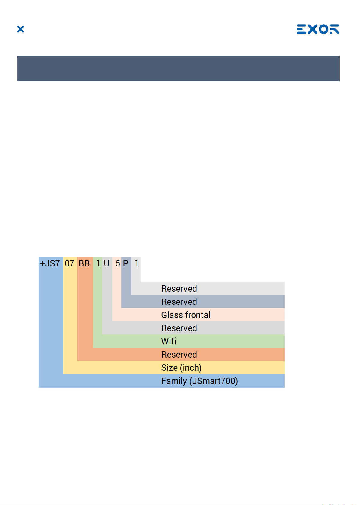
Product Identication
The product may be identied by the indications in the back cover. You will have to know the type of unit you
are using for correct usage of the information contained in the guide.
An example of the information reported is shown below:
product model name JSmart707
year/week of production 1920
serial number AA00012P9000000561AA
manufacturer address Exor International S.p.A.
Via Monte Fiorino 9
IT-37057 San Giovanni Lupatoto (VR)
Ordering code key
Example: +JS707BB1U5P1
MANUGENJSMART7xxW - Version 1.00
© 2019 EXOR International S.p.A. - Subject to change without notice
8
Page 9

3 Technical Specications
Touchscreen technology Projected capacitive - Multitouch
Back-up battery
3V 7mAh Vanadium-Lithium, rechargeable, not user-replacea
ble, model VL1220.
Flash 4GB (8GB for JSmart715 and JSmart721)
RAM 1GB (2GB for JSmart715 and JSmart721)
Hardware clock Clock/Calendar with back-up battery
Accuracy RTC (at 25°C) <100ppm
Environmental conditions
Operating temperature (surrounding -20 ÷ +55°C (vertical installation) EN 60068-2-14
air temperature)
Storage temperature -30 ÷ +80°C (JSmart707, 710) EN 60068-2-1
-20 ÷ +70°C (JSmart715, 721) EN 60068-2-2
EN 60068-2-14
Operating and storage humidity 5 ÷ 85 % RH not-condensing EN 60068-2-30
Vibrations 5 ÷ 9 Hz, 7 mm
9 ÷ 150 Hz, 1 g
Shock ± 50 g, 11 ms, 3 pulses per axis EN 60068-2-27
Protection class IP67 (requires appropriate connectoris EN 60529
and cables)
EN 60068-2-6
p-p
Electromagnetic Compatibility (EMC)
Radiated disturbance test Class A CISPR 22
CISPR 16-2-3
Electrostatic discharge immunity test 8 kV (air electrostatic discharge) EN 61000-4-2
4 kV (contact electrostatic discharge)
Radiated, radio-frequency, 80 MHz ÷ 1 GHz, 10V/m EN 61000-4-3
electromagnetic eld immunity test 1,4 GHz ÷ 2 GHz, 3 V/m
2 GHz ÷ 2.7 GHz, 1 V/m
Burst immunity test ± 2 KV dc power port EN 61000-4-4
± 1 KV signal line
Surge immunity test ± 0,5 KV dc power port (line to earth) EN 61000-4-5
± 0,5 KV dc power port (line to line)
± 1 KV signal line (line to earth)
Immunity to conducted disturbances
inducted by radiofrequency eld 0.15 ÷ 80 MHz, 10V EN 61000-4-6
Power frequency magnetic eld
immunity test Enclosure, 50/60Hz, 30A/m EN 61000-4-8
MANUGENJSMART7xxW - Version 1.00
© 2019 EXOR International S.p.A. - Subject to change without notice
9
Page 10

3 Technical Specications
Durability information
Backlight service life 40000 Hrs. or more
(LED type) (Time of continuos operation until the brightness of the
backlight reaches 50% of the rated value when the
surrounding air temperature is 25°C) - see Note 1
Note 1: Extended use in environments where the surrounding air temperature is 40°C or higher may
degrade backlight quality/reliability/durability.
Viewing angles
For the viewing angles values (U,D,R,L) of the display types, see the technical data of the respective device.
Legend: Display viewing angle
U From top
D From bottom
L From left
R From right
The viewing angles are specied for the horizontal (L,R) and vertical (U,D) axes in reference to the vertical
axis of the display. The specied viewing angles above always refer to the standard mounting orientation.
MANUGENJSMART7xxW - Version 1.00
© 2019 EXOR International S.p.A. - Subject to change without notice
10
Page 11

3 Technical Specications
Surface resistance
Chemical resistance of the front glass for an exposure time of 24 hours without visible changes:
• Betadine (10% Povidone Solution)
• Cola
• Electrode Gel/Paste
• Hydrogen Peroxide (3% Solution)
• NaCl (0.9% Solution)
• Coffee
• Dextrose (5% Glucose Solution)
• Hydrogen chloride (0.5% Solution PH=1)
• Isopropyl Alcohol
• Sodium Hypochlorit
• Ethyl Alcohol (70%-90%)
• Quaternary ammonium compound
MANUGENJSMART7xxW - Version 1.00
© 2019 EXOR International S.p.A. - Subject to change without notice
11
Page 12

3 Technical Specications
Properties multitouch PCAP touchscreen
Number of ngers 5
Glove operation Yes
Passive stylus pens Yes
Active stylus pens No
Hardened front glass Yes
Operation with gloves
Projected capacitive touch screens (PCAP) are suitable for operation with or without gloves.
A large number of gloves (rubber gloves, light/heavy leather gloves, disposable latex gloves, etc.) are supported.
Due to the variety of commercially available gloves, however, EXOR cannot guarantee all types.
MANUGENJSMART7xxW - Version 1.00
© 2019 EXOR International S.p.A. - Subject to change without notice
12
Page 13

4 Technical Data
Model JSmart707 JSmart710 JSmart715
Display /
Backlight
Colors 16M 16M 16M
Resolution 1024X600 1280X800 1366X768
Diagonal
(inches)
Viewing angles
horizontal
Viewing angles
vertical
Dimming yes to 0% yes to 0% yes
CPU
Operating
System
Flash 4GB 4GB 8GB
RAM 1GB 1GB 2GB
TFT Color / LED TFT Color / LED TFT Color / LED
7” widescreen 10.1” widescreen 15.6” widescreen
Direction L / Direction R
Typ. 75°
Direction U / Direction D
Typ. 75°
ARM Cortex-A9 dual core
800 MHz
Linux RT Linux RT Linux RT
Direction L / Direction R
Typ. 85°
Direction U / Direction D
Typ. 85°
ARM Cortex-A9 dual core
800 MHz
Direction L / Direction R
Typ. 80°
Direction U / Direction D
Typ. 80°
ARM Cortex-A9 quad core
800 MHz
Ethernet port 10/100 PoE 802.3af/at 10/100 PoE 802.3af/at 10/100 PoE 802.3af/at
USB port
Battery rechargeable rechargeable rechargeable
Real Time Clock yes yes yes
Power supply 802.3af 802.3af 802.3at
Current
consumption
Weight 0.7 Kg 1.2 Kg 4.0 Kg
1 (Host v. 2.0, request special
connector)
9W 12W 19W
1 (Host v. 2.0, request special
connector)
1 (Host v. 2.0, request special
connector)
MANUGENJSMART7xxW - Version 1.00
© 2019 EXOR International S.p.A. - Subject to change without notice
13
Page 14

4 Technical Data
Model JSmart721
Display /
Backlight
Colors 16M
Resolution 1920X1080
Diagonal (inches)
Viewing angles
horizontal
Viewing angles
vertical
Dimming yes
CPU
Operating
System
Flash 8GB
RAM 2GB
TFT Color / LED
21.5” widescreen
Direction L / Direction R
Typ. 89°
Direction U / Direction D
Typ. 89°
ARM Cortex-A9 quad core
800 MHz
Linux RT
Ethernet port 10/100 PoE 802.3af/at
USB port
Battery rechargeable
Real Time Clock yes
Power supply 802.3bt
Current
consumption
Weight 6.0 Kg
1 (Host v. 2.0, request special
connector)
32W
MANUGENJSMART7xxW - Version 1.00
© 2019 EXOR International S.p.A. - Subject to change without notice
14
Page 15

4 Technical Data
4.1 Dimensions
MODEL A B C
JSmart707 131.6mm/5.18” 195.2mm/7.68” 16,5mm/0.64” 17mm/0.66”
D
MODEL A B C
JSmart710 183.1mm/7.20” 264.5mm/10.41”
MANUGENJSMART7xxW - Version 1.00
© 2019 EXOR International S.p.A. - Subject to change without notice
D
16,5mm/0.64” 17mm/0.66”
15
Page 16

4 Technical Data
MODEL A B C
JSmart715 248mm/9.76” 398.6mm/15.69”
26,5mm/1.04” 17mm/0.66”
D
MODEL A B C
JSmart721 325.6mm/12.81” 534.1mm/21.02”
MANUGENJSMART7xxW - Version 1.00
© 2019 EXOR International S.p.A. - Subject to change without notice
D
26,5mm/1.04” 17mm/0.66”
16
Page 17

4 Technical Data
Rear view
MANUGENJSMART7xxW - Version 1.00
© 2019 EXOR International S.p.A. - Subject to change without notice
17
Page 18

4 Technical Data
4.2 Installation Environment and procedure
Avoid prolonged exposition to direct sunlight to avoid the risk of overheating the device.
The equipment is not intended for installation in contact with corrosive chemical compounds. Check the
resistance of the front panel to a specic compound before installation.
Do not use tools of any kind (screwdrivers, etc.) to operate the touch screen of the panel.
The IP67 is guaranteed only if:
• max deviation from the plane surface to the cut-out: O0.5mm
• thickness of the case where is mounted the equipment: from 1,5mm to 6mm
• max surface roughness where the gasket is applied: O120 um
MANUGENJSMART7xxW - Version 1.00
© 2019 EXOR International S.p.A. - Subject to change without notice
CAUTION
Tightening torque: 1000Ncm for nut, 130Ncm for screws
18
Page 19

4 Technical Data
4.3 Safety instruction
For all installation notes, please refer to the Installation Guide provided with the product.
!
MANUGENJSMART7xxW - Version 1.00
© 2019 EXOR International S.p.A. - Subject to change without notice
19
Page 20
5 Connections
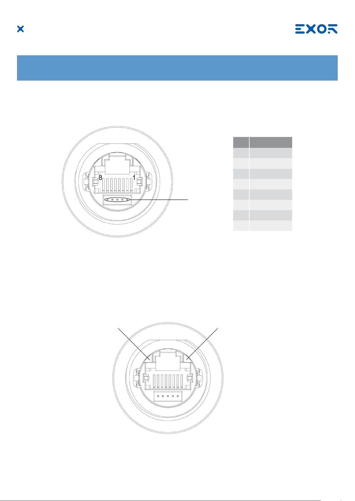
5.1 Ethernet Port
Pin Description
1 TX+
2 TX-
3 RX+
4 n/c
Reserved
The Ethernet port have two status indicators. Please see description in gure.
OFF: Valid link has NOT been detected
Red
ON: Valid link has been detected
Green
ON: No activity
BLINKING: Activity
5 n/c
6 RX-
7 n/c
8 n/c
MANUGENJSMART7xxW - Version 1.00
© 2019 EXOR International S.p.A. - Subject to change without notice
20
Page 21
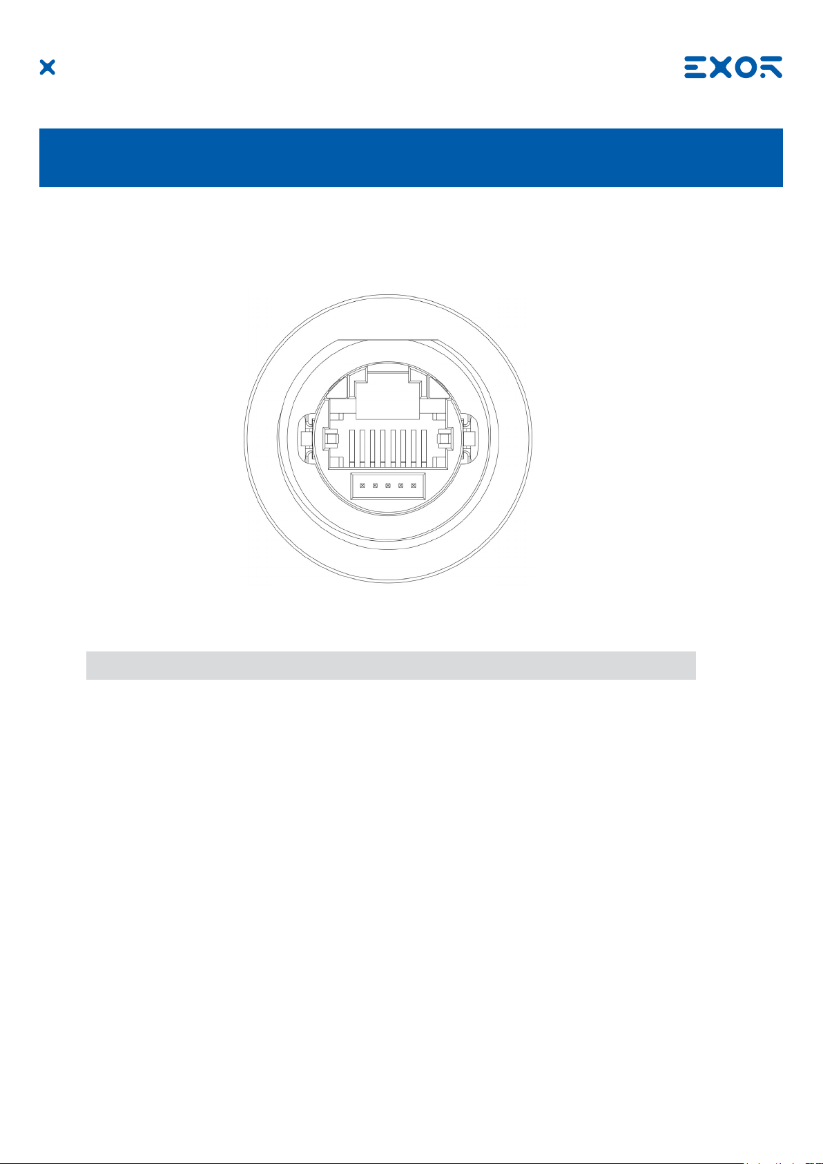
6 Power Supply, Grounding and Shielding
The power supply terminal block is shown in the gure below.
Fig. 6.1
Use a shielded CAT 5 cable or higher
Note: Ensure that the power supply has enough power capacity for the operation of the equipment.
The unit must always be grounded to earth with shielded CAT 5 cable. Grounding helps limit the effects of
noise due to electromagnetic interference on the control system.
The earth connection can also be made using the screws located near the connector. A label helps identify
the ground connection.
All the electronic devices in the control system must be properly grounded. Grounding must be performed
according to applicable regulations.
MANUGENJSMART7xxW - Version 1.00
© 2019 EXOR International S.p.A. - Subject to change without notice
21
Page 22
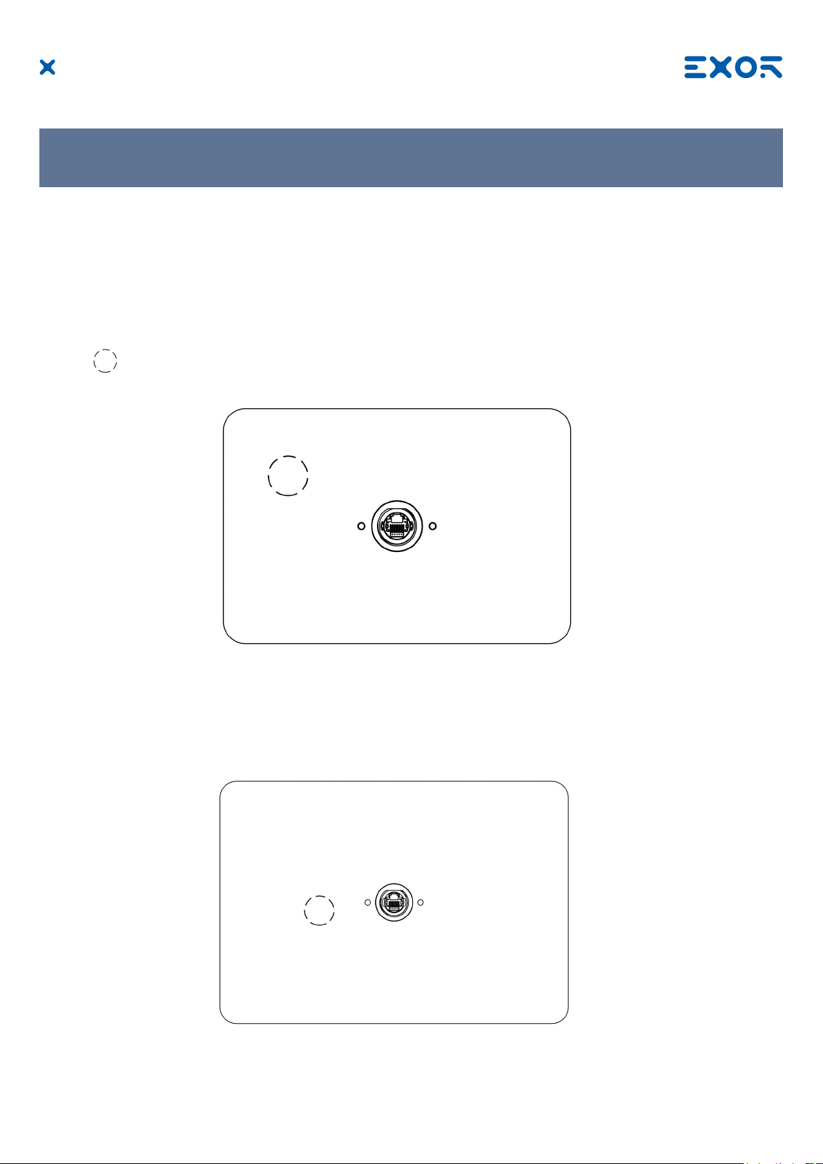
7 Battery
These devices are equipped with rechargeable Lithium battery, not user-replaceable.
The following information is maintained by the battery:
• hardware real-time clock (date and time)
Charge:
At rst installation must be charged for 48 hours.
When the battery is fully charged, it ensures a period of 3 months of date and time back-up at 25°C.
Battery
Fig. 7.2: JSmart707
Fig. 7.3: JSmart710
MANUGENJSMART7xxW - Version 1.00
© 2019 EXOR International S.p.A. - Subject to change without notice
22
Page 23

7 Battery
Fig. 7.4: JSmart715
ATTENTION
!
Dispose of batteries according to local regulations.
ATTENTION
!
This device cannot be disposed of as a domestic waste but according to WEEE European
Directive 2012/19/EU
MANUGENJSMART7xxW - Version 1.00
© 2019 EXOR International S.p.A. - Subject to change without notice
Fig. 7.5: JSmart721
23
Page 24

8 Special Instruction for Use
- The equipment shall only be used in an area of not more than pollution degree 2, as dened in IEC/EN 60664-1.
- The equipment shall be installed in an enclosure that provides a degree of protection not less than IP 54 in
accordance with IEC/EN 60079-15.
- Transient protection shall be provided that is set at a level not exceeding 140 % of the peak rated voltage
value at the supply terminals to the equipment.
- Install the HMI device according to the accompanying installation instructions.
- Ground the HMI device according to the accompanying installation instructions.
- Only qualied personnel may install the HMI device or repair it.
- Care shall be taken not to allow layers of dust to form on the graphic panel in a way that might cause the
accumulation of static charges. Keep the faceplate of the HMI device clean: the equipment must be cleaned only with a soft cloth and neutral soap product. Do not use solvents.
- This device should not be used for purposes and methods other than indicated in this document and
in the documentation accompanying the product.
9 Getting Started
JSmart 700 HMI products delivery conguration is based on a loader. Use the services of the loader to
install applications on the device such as JMobile runtime or browsers.
JMobile Studio version V2.6 or higher is required. JMobile Studio is a software tool that must be properly
installed on a computer running Microsoft Windows.
There are two options to transfer a JMobile application project to a HMI device:
Ethernet Connect the HMI device to the computer with an Ethernet network. In JMobile Studio
select the command Run/Download to target. You may have to ensure that the proper
rewall policy has been congured in the computer to allow JMobile Studio to access
the network.
USB Create an Update Package using JMobile Studio and copy it to a USB Flash drive
(to transfer via USB, use the dedicated accessory cable).
MANUGENJSMART7xxW - Version 1.00
© 2019 EXOR International S.p.A. - Subject to change without notice
24
Page 25
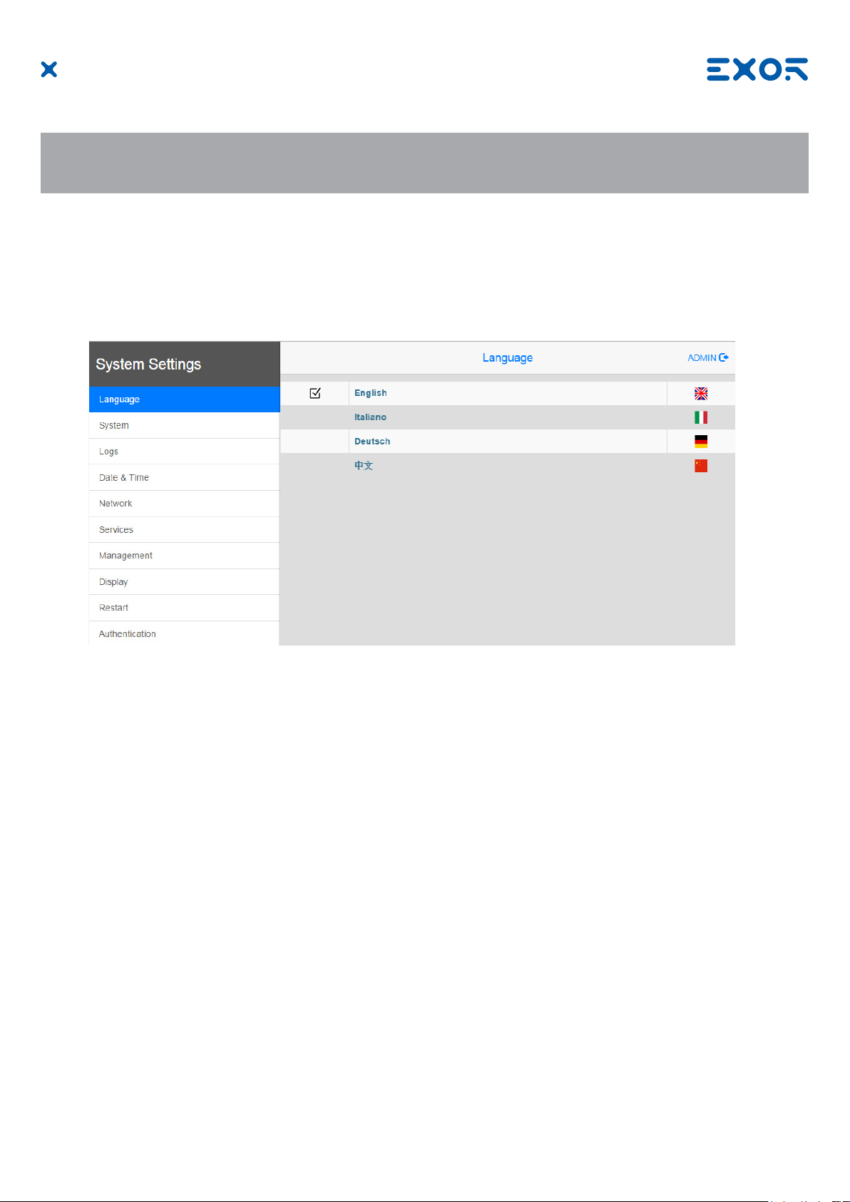
10 System Settings
JSmart 700 HMI products have a system settings interface to allow conguration of system options.
The user interface of System Settings is based on HTML pages accessible from the HMI screen or
remotely using a Web browser Chrome v44 or higher using port 443. To connect enter the address https://
IP/machine_cong where IP is the IP address of the HMI device. Default username is “admin”, default
password is “admin”. Use navigation menu on the left side of the screen to browse through the available
options.
The active item of menu is highlighted on the left side of the screen. The right side shows related
information and settings. Depending on the size of the HMI screen, both menu and content of selected item
may be shown on screen at the same time or not.
System Settings has two modes of operation:
User Mode JMobile runtime is running or the HMI device is in “factory default” status.
System Mode JMobile runtime is not running or the HMI device has a software failure.
System Mode includes all options available in User Mode and additionally includes
commands dedicated to system upgrade and recovery not available when running in
User Mode.
Activation of System Settings in User Mode:
Factory default status Press “System Setting” button on the HMI screen
JMobile runtime running Recall context menu and select “System Settings”. To recall the
context menu click and hold any unused area of the touchscreen
for a few seconds. Default hold time is 2 seconds.
MANUGENJSMART7xxW - Version 1.00
© 2019 EXOR International S.p.A. - Subject to change without notice
25
Page 26

10 System Settings
Activation of Systems Settings in System Mode:
Normal operation If JMobile runtime is not running: Press “System Setting” button on
the device screen to recall System Settings in User Mode. Select
“Restart” -> “Cong OS” to reboot in System Mode.
If JMobile runtime is running: recall context menu and select
“System Settings”. To recall the context menu click and hold any
unused area of the touchscreen for a few seconds. Default hold
time is 2 seconds to enter in System Settings in User Mode. Select
“Restart” -> “Cong OS” to reboot in System Mode.
Recovery operation If device is not responsive, use the so-called “tap-tap” procedure.
This procedure consists in tapping the surface of the touchscreen
during the device power-up phase. Tapping frequency must be high.
You have to start tapping the touchscreen as soon as power has been
applied to the device. When the sequence has been recognized, the
system shows the message: “TAP-TAP DETECTED”. At this point
release touch to boot in User Mode without running JMobile runtime
or press and hold few seconds (selecting so “RESTART: CONFIG
OS”) to boot in System Mode.
System Settings includes options for basic settings of the device:
Language Congure language used for System Setting menu only.
System Show information about platform, status and timers (like System on
time, backlight on time).
Logs Enable persistent log for BSP and allows exporting it.
Date & Time Change the device date and time, including time zone and NTP
Server
Network Congure IP Address of Ethernet interface and the other network
settings like DNS, Gateway, DHCP, Hostname, routing and
bridging.
Services Enable/disable services. Examples of services are: OpenSSH
server, Bridge, Cloud, Router, SNMP and logging.
Management Update of BSP components (Main OS, Cong OS, Boot loader,
XLoader), check for partitions consistence, update of splash
screen, information about usage and size of partitions. The
update of Main OS is available only in System Mode, the update
of Cong OS is only in User Mode.
Display Adjust display brightness, congure automatic backlight turnoff
and select HMI orientation (90°, 180°, 270° and 360°).
Restart Restart the device. “Main OS” option restarts the device in User
Mode, “Cong OS” option restarts the device in System Mode
showing System Settings.
Authentication Congure password for administrator (“admin”) and for the standard
user (“user”). Administrator has full access to System Settings
(updates of BSP and other system components). Standard user has
some limitations.
Note: Additional informations on System Settings are available in dedicated manual.
MANUGENJSMART7xxW - Version 1.00
© 2019 EXOR International S.p.A. - Subject to change without notice
26
Page 27

11 Unpacking and Packing Instructions
Fig. 11.1: JSmart707, JSmart710
Fig. 11.2: JSmart715, JSmart721
To repack the unit, please follow the instructions backwards.
MANUGENJSMART7xxW - Version 1.00
© 2019 EXOR International S.p.A. - Subject to change without notice
27
 Loading...