

Page 1

Tech-note
ePALM10 Product Manual
The ePALM10 is a state-of-the-art handheld HMI device with a graphic display and a keypad. The
rugged polyamide enclosure offers a high level of shock and environmental resistance making the
ePALM the ideal choice for use in the factory floor.
Contents
1
2
3
Highlights .......................................................................................................................... 3
Technical data ................................................................................................................... 4
Operation .......................................................................................................................... 6
3.1
Enabling Switches ................................................................................................ 6
3.2
Indicators and Keypad ......................................................................................... 6
3.3
Battery Replacement............................................................................................ 7
3.4
Power Supply and Grounding .............................................................................. 8
3.5
Applicable Regulations ........................................................................................ 9
3.6
Installation Environment ....................................................................................... 9
3.7
Cleaning Faceplates .......................................................................................... 10
3.8
Getting Started ................................................................................................... 10
3.8.1 Serial Communication ........................................................................................ 10
3.8.2 Ethernet Communication ................................................................................... 10
3.9
Troubleshooting ................................................................................................. 10
4
5
Connections .................................................................................................................... 11
4.1
Serial Communication - Types –0061 and –0062 .............................................. 11
4.1.1 Using Optional Fieldbus Modules ...................................................................... 14
4.1.2 Connecting the ePALM to the Simatic S7 MPI network ..................................... 15
4.2
Ethernet Communication - Type –0066 and –0068 ........................................... 16
4.3
Profibus DP Communication - Type –0067 and –0069 ..................................... 19
4.3.1 Termination switch ............................................................................................. 21
4.3.2 Programming connector ..................................................................................... 22
Accessories ..................................................................................................................... 23
tn202-2.doc - 10.01.2012
ePALM10 Product Manual
1
Page 2

www.uniop
.com
Tech-note
Tn202
Ver. 1.02
Copyright 2004-2012 Exor International S.p.A. – Verona, Italy
Subject to change without notice
The information contained in this document is provided for informational purposes only. While
efforts were made to verify the accuracy of the information contained in this documentation, it is
provided “as is” without warranty of any kind.
tn202-2.doc - 10.01.2012
ePALM10 Product Manual
2
Page 3

Tech-note
1 Highlights
• Graphical display 120x64 pixels (up to 8 lines
20 characters)
• Highly visible transflective LCD display
• 27-keys keypad with tactile feedback
• Connection to industrial bus systems
• Large memory size (512 KB Flash)
• IP65 protection
• Includes Emergency Stop button
• Includes enabling switches, normal or 3-
positions
• Available in version for connection to Ethernet
and Profibus DP
The ePALM HMI panels are the handheld products of the UniOP family. All of the ePALM products
support the rich common functionality of the UniOP operator panels:
• Versions available for connection to
Ethernet and Profibus DP. Ethernet
version allows connection to field devices
as well as programming the HMI from
Designer.
• Powerful and intuitive programming with
the UniOP Designer 6 software
• Support of more than 130 communication
drivers for industrial devices
• Transflective LCD display ensures
readability under the most critical light
conditions
• Display dynamic data in numerical, text,
bargraph and graphic image formats
• Recipe data storage. Recipe data can be
transferred to a host computer using the
Ethernet connection.
• Multilanguage applications. The number
of runtime languages is limited only by the
available memory. All text information in
the application can be exported in Unicode
format for easier translation.
• Powerful macro editor to configure
keypad operation
• Alarms and historical alarm list. Alarm
and event information can be printed or
transferred to a host computer using the
Ethernet connection.
• Eight level password protection.
• Report printing to serial printer. Reports
are freely configurable using Designer.
• Ethernet-based UniNet network to share
data between UniOP HMIs and to serve
data using UniNet OPC Server.
In addition some unique features make the
ePALM10 a perfect fit for handheld operation.
• Emergency Stop button. Hardwired.
• Enabling switches. Hardwired.
• High-quality polyurethane cable for
mobile applications.
tn202-2.doc - 10.01.2012
ePALM10 Product Manual
3
Page 4

Display
Memory
Front panel
Interfaces
Functionality
Replace with same component
Ratings
Environmental
Electromagnetic
Dimensions
Tech-note
2 Technical data
Type Transflective LCD
monochrome
Resolution 120x64 pixel
Active display area 66x33 mm
Backlight LED
Dimming Contrast Software
User memory 512 KB Flash
User memory
expansion
Touch screen Function keys 9
System keys 18
User LED’s 20
System LED’s 5
PC/Printer port See below
PLC port See below
Aux port (fieldbus and
Ethernet)
Serial programming
speed
Vector graphics Dual driver capability Data acquisition and
trends
Recipe memory 16 KB
UniNet network Client/Server
Alarms 1024
Event list 256
Password Yes
Hardware RTC Yes, battery backed
Screen saver Buzzer Battery 3 V 270 mA Lithium, non
-
See below
9600 – 38400 bps
-
rechargeable, user
replaceable, model CR2430.
or equivalent compatible with
the operating temperature of
the product.
Power supply voltage 18 - 30 VDC
Current consumption ~ 300 mA at 24 VDC
Fuse Automatic
Weight ~ 0.5 Kg (not including cable)
Min thickness of cable 7 mm diameter
Max thickness of cable 11 mm diameter
Conditions
Operating temperature
Storage temperature
Operating and storage
humidity
Vibrations
Shock 50 g, 11 ms, 3 pulses per axis
Protection class IP65
Keyboard reliability > 3 million operations
Compatibility (EMC)
Emitted interference Class A
Immunity to radiated
radiofrequency
electromagnetic field
Immunity to conducted
disturbances inducted
by radiofrequency field
Fast transient 2 KV power supply
Electrostatic discharge 8 KV in air
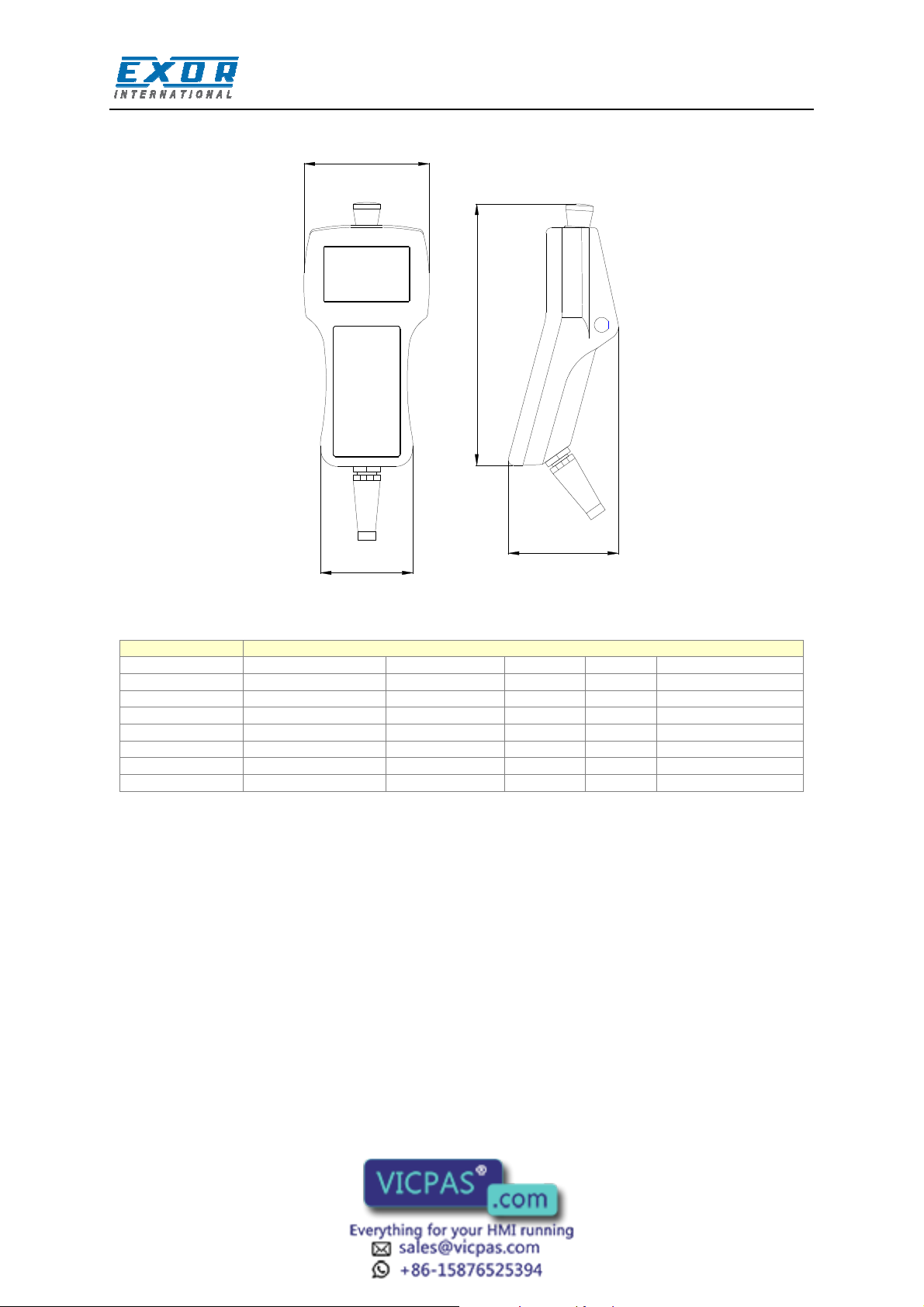
A 116 mm (4.56“)
B 86 mm (3.38“)
C 102 mm (4.01”)
D 239 mm (9.41”)
0 to 50 °C
EN 60068-2-14
-20 to +70 °C
EN 60068-2-14
5 – 85 % RH non-condensing
EN 60068-2-30
10 ÷ 57 Hz, 0,075 mm peak
57 ÷ 150 Hz, 1 G
EN 60068-2-6
EN 60068-2-27
EN 60529
EN 60529
EN 55011
80 MHz ÷ 1 GHz, 10 V/m
EN 61000-4-3
900 MHz, 10V/m
ENV 50204
0.15 ÷ 80 MHz, 10 V
EN 61000-4-6
1 KV signal lines
EN 61000-4-4
EN 61000-4-2
The product is designed for installation in industrial environments in compliance with the regulations:
Emitted interference EN 61000-6-4, 2001
Noise immunity EN 61000-6-2, 2001
All circuits in this handheld product, including the wiring of the emergency stop button and the
enabling switches, must be considered SELV circuits. They will have to be wired in compliance with
EN 60950.
tn202-2.doc - 10.01.2012
ePALM10 Product Manual
4
Page 5
Model
Cable Type/Length
PC/Printer Port
PLC Port
Module
Enabling switches
Tech-note
A
D
C
B
Figure 1 – Side and front view
ePALM10-0061 Serial/5m Yes Yes - two normal
ePALM10-0062 Serial/10m Yes Yes - two normal
ePALM10-3P61 Serial/5m Yes Yes - one 3-position
ePALM10-3P62 Serial/10m Yes Yes - one 3-position
ePALM10-0066 Ethernet/5m - - SCM11 one 3-position
ePALM10-0068 Ethernet/10m - - SCM11 one 3-position
ePALM10-0067 Profibus DP/10m Yes - TCM08 one 3-position
ePALM10-0069 Profibus DP/5m Yes - TCM08 one 3-position
tn202-2.doc - 10.01.2012
ePALM10 Product Manual
5
Page 6
Position
Button status
Contacts
Func
tion
Uni
UniUni
Uni
Tech-note
3 Operation
3.1 Enabling Switches
Enabling switches are implemented in two different solutions in the various ePALM models:
Two independent 2-positions switches with NO contacts
One 3-positions switch with two NO contacts
The operator must operate the two independent 2-positions switches simultaneously. The two
normally open contacts are wired directly to the controller.
The 3-positions switch must be operated as described in the table.
1 Released Open Not enabled
2 Pressed Closed Enabled
3 Pressed completely Open Panic
The switch provides two normally open contacts to be wired directly to the controller.
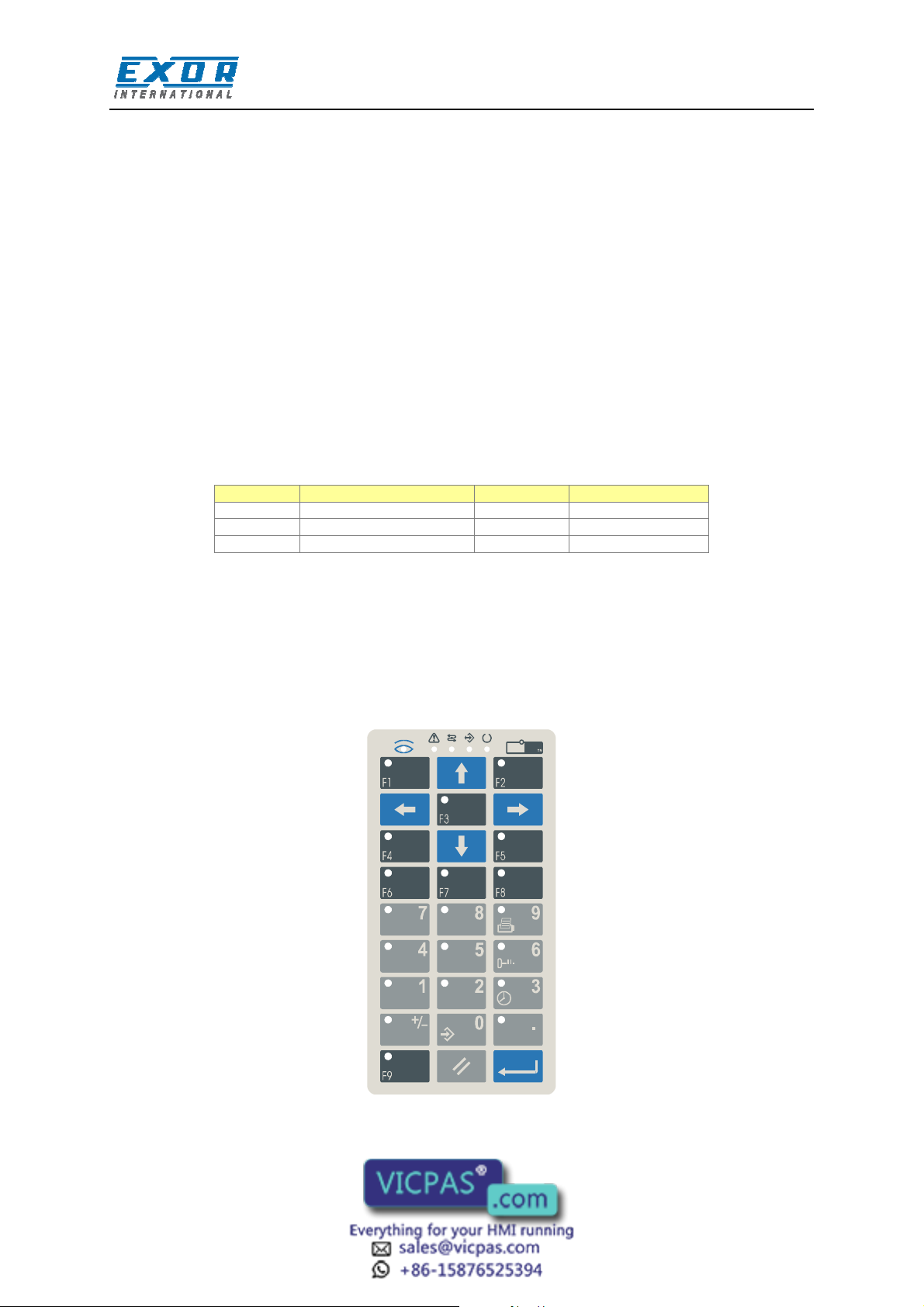
3.2 Indicators and Keypad
The standard keypad of the ePALM panels is shown in the figure below.
Custom artwork may be designed and produced on request. Please inquire for more information.
OP
OP
OPOP
091A
Figure 2 – Keypad layout
tn202-2.doc - 10.01.2012
ePALM10 Product Manual
6
Page 7
LED Color
Status
Meaning
RDA Bit
LED on Key
RDA Bit
LED on Key
Tech-note
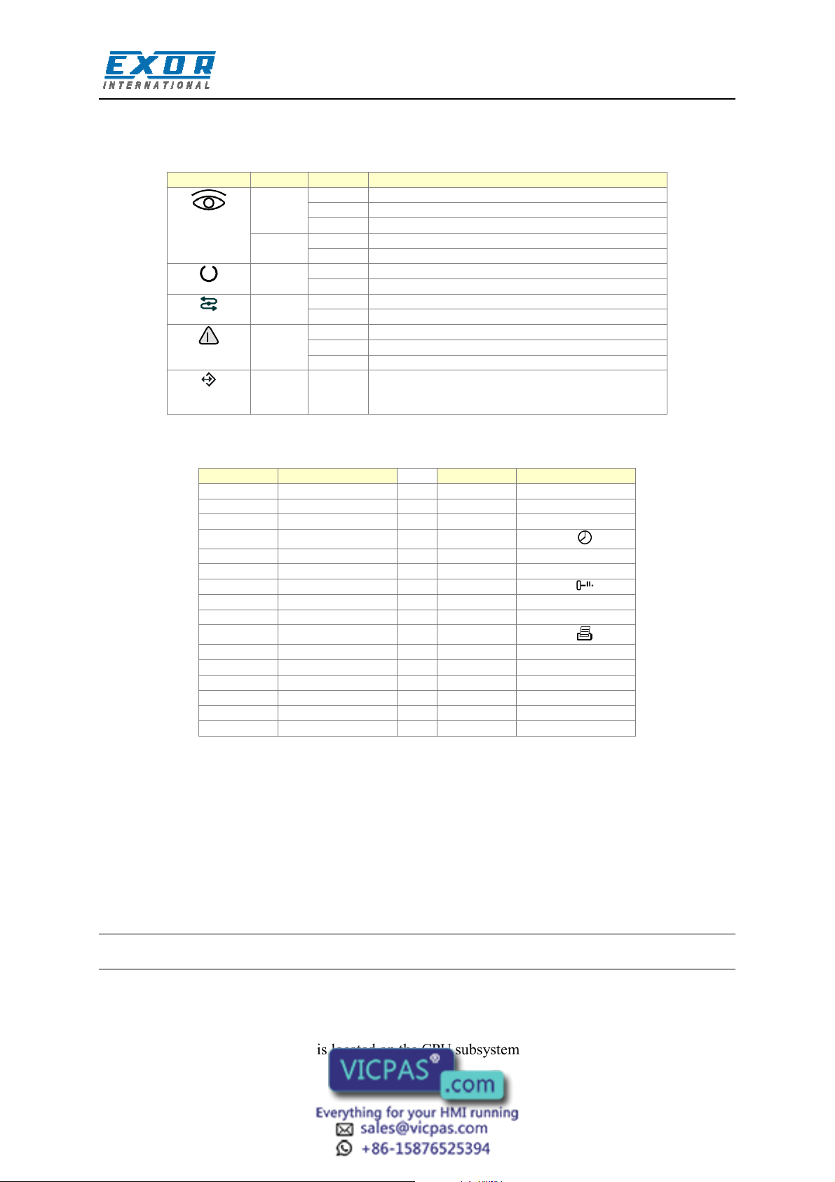
There are several dedicated LED indicators on the front panel of the unit. Functions are described in
the table below.
Red OFF No hardware problems detected
Green OFF No key pressed
Green OFF Hardware fault
Green BLINK Communication error
Red OFF No alarms
Green May be user controlled as LED number 65 using
BLINK Battery low
ON Hardware fault
ON While any key is pressed (visual feedback)
ON Unit in operation
ON Communication OK
BLINK Alarm requires acknowledgment
ON Alarm active
the Macro Editor. Turns ON when recipe/event
backup is being performed.
The RDA mapping of LED indicators is shown in the table below.
L1 F1 L17
L2 F2 L18 1
L3 F3 L19 2
L4 F4 L20
L5 F5 L21 4
L6 F6 L22 5
L7 F7 L23
L8 F8 L24 7
L9 F9 L25 8
L10 L26
L11 L27 .
L12 L28 +/-
L13 L29
L14 L30
L15 L31
L16 L32
3 /
6 /
9 /
The RDA mapping of the keypad is standard.
3.3 Battery Replacement
A Lithium battery is required for data back-up. The battery maintains the following data:
• Hardware real time clock
• Event list
• Recipe data
Note: replacing the battery will cause the loss of the data maintained by the battery.
To replace the battery follow the procedure listed below:
1) turn off the power to the device
2) using a screwdriver loose the 6 screws securing the plastic enclosure
3) open the handheld; the battery is located on the CPU subsystem
4) remove the battery
tn202-2.doc - 10.01.2012
ePALM10 Product Manual
7
Page 8

Tech-note
Warning: danger of explosion if battery is incorrectly replaced. Replace only with the same or
equivalent type recommended by the manufacturer. Dispose of used batteries according to the
manufacturer’s instructions.
5) replace the battery with a new one
6) close the handheld and tighten the six screws
7) apply power to the handheld and check that the battery good status is reported.
Figure 3 – Battery replacement
3.4 Power Supply and Grounding
The unit must always be grounded to protection earth (PE). Grounding helps limit the effects of noise
due to electromagnetic interference on the control system.
The power supply circuit may be floating or grounded. In the latter case connect to ground the power
source common as shown in figure 4 with a dashed line.
When using the floating power scheme, note that the panels internally connect the power common to
ground with a 1 MΩ resistor in parallel with a 3,3 nF capacitor.
The power supply must have double or reinforced insulation
The suggested wiring for the power supply is shown in figure 4.
tn202-2.doc - 10.01.2012
ePALM10 Product Manual
8
Page 9

L1
M
ePALM
L+
Tech-note
N
PE
AC
DC
Figure 4 - Power supply
All the electronic devices in the control system must be properly grounded. Grounding must be
performed according to applicable regulations.
3.5 Applicable Regulations
Regulations and recommendations have been issued in Europe covering the main safety-related issues
in control systems, which include operator interfaces.
EN 60204-1 lists some important guidelines applicable when using operator interfaces.
9.2.4 Suspension of safeguards
9.2.5.3 Stop
9.2.5.4 Emergency stop
9.2.5.6 Hold-to-run controls
9.2.5.7 Two-hand controls
9.4 Control function in case of failure
Do not use operator interface to directly command motors, valves or other actuators not equipped with
safeguards and potentially harmful to persons or equipment in case of fault to the unit.
The service personnel, when operating directly on the powered unit, must be electrostatically
discharged.
All safety related regulations must be observed.
Warning: do not open the rear cover of the device when power is on.
3.6 Installation Environment
The equipment is not intended for continuous exposure to direct sunlight. This might accelerate the
aging process of the front panel film.
The equipment is not intended for installation in contact with corrosive chemical compounds. Check
the resistance of the front panel film to a specific compound before installation.
tn202-2.doc - 10.01.2012
ePALM10 Product Manual
9
Page 10

Tech-note
Do not use tools of any kind (screwdrivers, etc.) to operate the keyboard.
3.7 Cleaning Faceplates
The equipment must be cleaned only with a soft cloth and neutral soap product. Do not use solvents.
3.8 Getting Started
ePALMs must be programmed with the Designer software.
To program an ePALM you will have to connect it to a personal computer running the Designer
software; the ePALM must be in Configuration mode to be programmed.
3.8.1 Serial Communication
Make sure that Designer is correctly configured to communicate with the communication port to
which the cable attached.
The serial communication parameters between the panel and the personal computer are:
speed: 9600/38400 baud
parity: None
stop bit: 1
The Designer software defaults to the correct parameters.
3.8.2 Ethernet Communication
When applicable, Designer can use Ethernet to connect to the panel. Make sure all network
parameters are properly set to ensure communication between Designer and the panel.
The version of Designer software must be compatible with the firmware version of the panel to be
programmed. Call technical support for more information on compatibility between firmware and
programming software.
3.9 Troubleshooting
In the case it might be impossible to switch the handheld to Configuration Mode due to problems in
the start-up phase, follow the procedure described below:
1.
Switch off the unit
2.
Press and hold any 3 keys
3.
Turn on the unit and hold the keys pressed until Configuration Mode will be shown on the screen.
tn202-2.doc - 10.01.2012
ePALM10 Product Manual
10
Page 11

CN3
CN4
Tech-note
4 Connections
The ePALM10 is available in several versions, featuring different communication cables and different
solutions for the enabling switches.
4.1 Serial Communication - Types –0061 and –0062
ePALM types –0061 and -0062 include all standard UniOP connections and are suitable for all
common serial communication links.
The ePALM10-0061 includes a communication cable with a length of 5 meters.
The ePALM10-0062 includes a communication cable with a length of 10 meters.
The cable does not have a connector at its loose end as it is intended to be wired directly in the control
cabinet.
The following groups of signals are available in the cable:
PC/Printer Port
PLC Port
Aux Port
Power
Emergency Stop button – two NC contacts
Two 2-positions enabling switches – NO contacts
In all the most common configurations, the signals are wired to the cable and there will be no need to
open the unit to access the terminal blocks.
Note: the ePALM10 unit does not include a current loop (20 mA) interface in the PLC port. The
communication modules TCM04 (Interbus), TCM07 (Simatic S7 MPI without optical
insulation), TCM08/TCM18 (Profibus DP) and TCM10/SCM11 (Ethernet) are not supported.
Internally to the product all signals, excluding emergency stop, are wired to a detachable interface
board with five terminal blocks.
The position of the terminal blocks and the numbering of the contacts are shown in the figure below.
CN2
CN1
CN5
Figure 5 – Interface Board
tn202-2.doc - 10.01.2012
ePALM10 Product Manual
11
Page 12

CN1 Aux Port
CN2 PC/Printer Port
CN3 PLC Port
CN4 Power
CN5 Additional Signals
Tech-note
The assignment of the signals on the terminal blocks is shown in the tables below. Terminals
indicated as ‘Reserved’ should not be connected.
1 Aux Port pin 5 1 Reserved
2 Aux Port pin 9 2 Reserved
3 Aux Port pin 4 3 Reserved
4 Aux Port pin 8 4 Reserved
5 Aux Port pin 3 5 +5V output (max 100 mA)
6
Aux Port pin 7
7 Aux Port pin 2 7 RXD
8 Aux Port pin 6 8 CTS
9 Aux Port pin 1 9 TXD
10 Reserved 10 RTS
6 GND
The terminal assignment in CN1 refers to the corresponding assignment in the Aux Port of the
standard panel-mount version of the product. This correspondence will be useful to adapt the normal
cable drawings for use with the handheld device.
1 CHA+ 1 +24 VDC
2 CHA- 2 Common
3 CHB+ 3 Reserved
4 CHB- 4 PE
5 +5V output (max 100 mA)
6 GND
7 RXD 1 Enabling switch R (NO contact)
8 CTS 2 Enabling switch R (NO contact)
9 TXD 3 Enabling switch L (NO contact)
10 RTS 4 Enabling switch L (NO contact)
The Emergency Stop button is hardwired directly to the cable: the corresponding signals are not
available in the connectors.
The wires in the cable are color-coded according to the table below.
tn202-2.doc - 10.01.2012
ePALM10 Product Manual
12
Page 13

Signal
Color
S mm
2
AWG (approx)
Power
PC/Printer Port
PLC Port
Additional Signals
Emergency Stop
Tech-note
+24 VDC Red 0.5 20
Common Black 0.5 20
GND Grey 0.14 26
RXD Orange 0.14 26
CTS Brown 0.14 26
TXD White 0.14 26
RTS Pink 0.14 26
+5V Output Green 0.14 26
CHA+ Blue-Red 0.14 26
CHA- Blue-Black 0.14 26
CHB+ Violet-Red 0.14 26
CHB- Violet-Black 0.14 26
+5V Output Red 0.14 26
GND Black 0.14 26
RXD Brown-Pink 0.14 26
CTS Green-Pink 0.14 26
TXD Orange-Pink 0.14 26
RTS Yellow-Pink 0.14 26
ES Right (NO) Cyan-Black 0.35 22
ES Right (NO) Cyan 0.35 22
ES Left (NO) Blue-Black 0.35 22
ES Left (NO) Blue 0.35 22
E-Stop 1 (NC) Green 1 17
E-Stop 1 (NC) Yellow 1 17
E-Stop 2 (NC) Brown 1 17
E-Stop 2 (NC)
Orange 1 17
Note: the wiring of the Emergency Stop button is to be considered a SELV circuit and it is
intended only for connection to low voltage circuits (below 48 VDC).
The standard cable layout of the ePALM10-0061 and ePALM10-0062 includes the signals of the
PC/Printer Port and the signals of the PLC Port. Without modifications it allows to connect to the
handheld device for programming and to set-up a connection to a field device using RS-232, RS-422
or RS-485.
If connection to the Aux Port is required, signals normally wired to the PLC port will have to be
manually moved to the Aux Port. You will have to open the product to perform this operation.
When the RS-422 or RS-485 communication is used, it is recommended not to leave the RXD and the
CTS signals floating, even if they are not used in this configuration. The RXD signal should be
connected to GND; the CTS signal should be connected to the +5V Output.
tn202-2.doc - 10.01.2012
ePALM10 Product Manual
13
Page 14

Connect the
Shield Trace
Ferrite Toroid
E
Max Wire Length 10cm
Tech-note
N
G
N
.
C
.
N
E
.
.
.
E
C
C
C
R
.
.
.
N
N
N
G
E
W
N
Y
T
K
I
A
E
O
N
H
R
R
R
I
P
W
B
O
G
To Emergency Stop
Button
N.C.
N.C.
N.C.
N.C.
N.C.
N.C.
N.C.
N.C.
N.C.
N.C.
CYAN-BLACK
CYAN
BLUE-BLACK
BLUE
YELLOW
GREEN
BROWN
ORANGE
Length 25cm
4X1mmq
BLUE-RED
BLUE-BLACK
VIOLET-RED
VIOLET-BLACK
RED
BLACK
BROWN-PINK
GREEN-PINK
ORANGE-PINK
YELLOW-PINK
RED
BLACK
N.C.
SHIELD TRACE
Figure 6 – Wiring layout
The figure shows the standard assembly of the communication cable.
Please note that the ferrite toroid is required for proper operation and should not be removed.
To program the ePALM10 you will need to wire at least the power supply and the programming port
connections. Connect the ePALM10 to the COM port of a PC as indicated in the figure below.
Figure 7 – Programming cable
4.1.1 Using Optional Fieldbus Modules
The ePALM versions –0061 and –0062 are compatible with some of the standard TCM
communication modules for connection to fieldbus systems.
The list of the TCM module currently supported by the ePALM product is the following:
tn202-2.doc - 10.01.2012
ePALM10 Product Manual
14
Page 15

TCM module
Fieldbus
Notes
CN1 Connector (Aux Port)
CN3 Connector (PLC Port)
Pin
Signal
Color
Pin Signal
Tech-note
TCM01 Siemens Simatic S7 MPI Suitable for a point-to-point configuration at the speed
TCM02
TCM03
TCM09 CANopen There are limitations in the bus speed and network
Moeller Suconet K
DeviceNet
of 187 Kb
Suitable for a point-to-point configuration at the
maximum speed of 375 Kb
There are limitations in the bus speed and network
configuration that can be used
configuration that can be used
Other TCM modules are currently not supported for use in these versions of the ePALM product.
The following notes are important:
• The TCM module must be plugged into the unit in the slot available for this purpose. The ePALM
must be opened to allow for the insertion of the TCM module. After plugging the module the
ePALM product must be carefully closed to ensure proper sealing.
• The default wiring of the Aux Port CN1 must be manually changed to connect the appropriate
signals. Fieldbus topologies do not allow long (5-10 meters) drop segments; the wiring must
include incoming and outgoing segments for all bus signals.
• The CA01 interface board does not allow adding terminator resistors to the bus lines. The ePALM
cannot be used a final node in the network topology unless termination resistors are applied
externally.
The most common wiring layouts will be described in detail in this chapter.
4.1.2 Connecting the ePALM to the Simatic S7 MPI network
It is recommended that the signals needed for this connection be moved from the CN3 connector
(PLC Port) to the CN1 connector (Aux Port) as shown in the table below.
The table indicates the wires that must be moved from CN3 to CN1. The signals A and B will have to
be connected to the MPI network.
Please note that it is not possible to connect the termination resistors in the ePALM.
Wires to be removed
4 A Blue-Red 1 CHA+
5 B Blue-Black 2 CHA1 GND Black 6 GND
tn202-2.doc - 10.01.2012
ePALM10 Product Manual
15
Page 16

CN4
CN2
CN3
Ethernet port
Tech-note
4.2 Ethernet Communication - Type –0066 and –0068
ePALM type –0066 and –0068 have been designed exclusively for connection to the Ethernet
network. The products include a special cable suitable for Ethernet communication.
The cable does not have a connector at its loose end as it is intended to be wired directly to the control
cabinet.
The following groups of signals are available in the cable:
Ethernet 10base/T
Power
Emergency Stop button – two NC contacts
One three-positions enabling switch – two independent NO contacts
Please note that this product does not include connections for the following standard ports:
PC/Printer Port,
PLC Port,
Aux Port.
Note: this version of the product does not include the conventionalPC/Printer Port; programming
can be done only via Ethernet.
Internally to the product all signals, excluding emergency stop, are wired to a detachable interface
board with five terminal blocks.
The position of the terminal blocks and the numbering of the contacts are shown in the figure below.
CN7
CN3
CN1
Figure 8 – Interface board
The assignment of the signals on the terminal blocks is shown in the tables below. Terminals
indicated as ‘Reserved’ should not be connected.
tn202-2.doc - 10.01.2012
ePALM10 Product Manual
1 RX2 RX+
3 TX4 TX+
16
Page 17

CN1 Additional Signals
CN2 Power
CN4 PLC Port
Signal
Color
S mm
2
AWG (approx)
Power
Ethernet Port
Additional Signals
Emergency Stop
Tech-note
1 Enabling switch A (NO contact) 1 +24 VDC
2 Enabling switch A (NO contact) 2 Common
3 Enabling switch B (NO contact) 3 Reserved
4 Enabling switch B (NO contact) 4 PE
The Emergency Stop button is hardwired directly to the cable: the corresponding signals do not
appear listed in the connectors.
Note: the wiring of the Emergency Stop button is to be considered a SELV circuit and it is
intended only for connection to low voltage circuits (below 48 VDC).
1 CHA+
2 CHA3 CHB+
4 CHB5 +5V output (max 100 mA)
6 GND
7 RXD
8 CTS
9 TXD
10 RTS
Note: the signals in CN4, although fully functional, are not wired to the connection cable and are
not available for applications. The information on CN4 is provided for reference only. The
signals wired to the cable are listed in the table below.
The wires in the cable are color-coded as shown in the table below.
+24 VDC Red 0.75 20
Common Black 0.75 20
TX+ White-Orange 0.5 24
TX- Orange 0.5 24
RX+ White-Green 0.5 24
RX- Green 0.5 24
Enabling Switch A Blue-Black 0.75 22
Enabling Switch A Blue 0.75 22
Enabling Switch B Cyan-Black 0.75 22
Enabling Switch B Cyan 0.75 22
E-Stop 1 (NC) Green 1 17
E-Stop 1 (NC) Yellow 1 17
E-Stop 2 (NC) Brown 1 17
E-Stop 2 (NC) Orange 1 17
The internal layout of the communication cable is shown in the figure. Please note that the ferrite
toroid is required for proper operation and should not be removed.
tn202-2.doc - 10.01.2012
ePALM10 Product Manual
17
Page 18

SHIELD TRACE
Tech-note
WHITE-ORANGE
ORANGE
WHITE-GREEN
GREEN
CYAN-BLACK
BLUE-BLACK
CYAN
BLUE
RED
BLACK
N.C.
YELLOW
GREEN
BROWN
ORANGE
Figure 9 – Wiring layout
tn202-2.doc - 10.01.2012
ePALM10 Product Manual
18
Page 19

CN2
CN3
CN4
CN1 Profibus DP
Tech-note
4.3 Profibus DP Communication - Type –0067 and –0069
ePALM type –0067 and –0069 have been designed exclusively for connection to the Profibus DP
fieldbus. The products include a special cable suitable for Profibus DP communication.
The cable does not have a connector at its loose end as it is intended to be wired directly in the control
cabinet.
The following groups of signals are available in the cable:
Profibus DP
Power
Emergency Stop button – two NC contacts
One three-positions enabling switch – two independent NO contacts
Please note that this product does not include connections for the following standard ports:
PLC Port,
Aux Port.
Note: this version of the product has a special connector for programming. See below for
description
Internally to the product all signals, excluding emergency stop, are wired to a detachable interface
board with six terminal blocks.
The position of the terminal blocks and the numbering of the contacts are shown in the figure below.
SW1
CN1
CN5
Figure 10 – Interface board
The assignment of the signals on the terminal blocks is shown in the tables below. Terminals
indicated as ‘Reserved’ should not be used.
1 Reserved
2 Reserved
3 Reserved
4 A
5 B
6 Reserved
7 Reserved
8 Reserved
tn202-2.doc - 10.01.2012
ePALM10 Product Manual
19
Page 20

CN5 Additional Signals
CN4 Power
Signal
Color
S mm
2
AWG (approx)
Tech-note
9 Reserved
10 Reserved
1 Enabling switch A (NO contact) 1 +24 VDC
2 Enabling switch A (NO contact) 2 Common
3 Enabling switch B (NO contact) 3 Reserved
4 Enabling switch B (NO contact) 4 PE
The Emergency Stop button is hardwired directly to the cable: the corresponding signals do not
appear listed in the connectors.
Note: the connection of the Emergency Stop button is intended only for connection to low voltage
circuits (below 48 VDC).
The wires in the cable are color-coded according to the table below.
Power
+24 VDC Red 0.75 21
Common Black 0.75 21
Aux Port (Profibus)
A Green 0.5 24
B Red 0.5 24
Additional Signals
Enabling switch A Blue-Black 0.75 21
Enabling switch A Blue 0.75 21
Enabling switch B Cyan-Black 0.75 21
Enabling switch B Cyan 0.75 21
Emergency Stop
Emergency Stop 1 Green 1 17
Emergency Stop 1 Yellow 1 17
Emergency Stop 2 Brown 1 17
Emergency Stop 2 Orange 1 17
The internal layout of the communication cable is shown in the figure below. Please note that the
ferrite toroid is required for proper operation and should not be removed.
tn202-2.doc - 10.01.2012
ePALM10 Product Manual
20
Page 21

SHIELD TRACE
Tech-note
RED
GREEN
CYAN-BLACK
CYAN
BLUE-BLACK
BLUE
RED
BLACK
N.C.
YELLOW
GREEN
BROWN
ORANGE
Ferrite Toroid
Figure 11 – Wiring layout
4.3.1 Termination switch
The ePALM has been designed only for connection at one of the two ends of the Profibus DP
network.
ePALM10
Profibus DP
Figure 12 – Network topology
Profibus-DP requires termination of the bus at both end points; see the Profibus-DP specifications for
details. The ePALM includes the bus terminator resistors. Make sure they are always switched on.
tn202-2.doc - 10.01.2012
ePALM10 Product Manual
21
Page 22

Termination
Setting
Switch Position
Pin Signal
Tech-note
Open (not used) Off
On
(Default)
Figure 13 – Termination resistors
4.3.2 Programming connector
On the back of the ePALM a RS-232 serial port is available for programming the device; the drawing
below shows the position and the pin-out of the connector.
7
1
Figure 14 – Programming connector
1 NC
2 +5VDC out
3 RX
4 TX
5 RTS
6 CTS
7 GND
Use cable CA234 to connect the ePALM to a Personal Computer for programming. The cable
diagram is shown in the figure below.
tn202-2.doc - 10.01.2012
ePALM10 Product Manual
22
Page 23

Tech-note
Figure 15 – Programming cable
5 Accessories
The following accessories are currently available for the ePALM10 products:
• hooks for hanging the handheld device. Hooks are available in two versions, AHOOK01 without
magnet and AHOOK02 with a magnet.
The hook with the magnet is shown in the figure below.
Figure 16 – Hook with magnet
The hook with magnet cannot be used with type –0067.
tn202-2.doc - 10.01.2012
ePALM10 Product Manual
23
 Loading...