


RSV
DK
DE
SE
UK
NO
NL
FR

2
3000113 RSV 2012-10-05
1. UK – Product information ..........................................................................................................3
1.1 Construction and design ................................................................................................. 3
1.2 Installation instructions .................................................................................................. 4
1.3 Wiring ...............................................................................................................................8
1.4 Service and cleaning ........................................................................................................9
1.5 Technical specications ................................................................................................... 9
1.6 Warranty ...........................................................................................................................9
2. DE – Produktinformation .........................................................................................................10
2.1 Produktbeschreibung ...................................................................................................10
2.2 Mechanische Montage ..................................................................................................11
2.3 Elektrischer Anschluß ....................................................................................................15
2.4 Wartung und Reinigung ................................................................................................16
2.5 Technische Daten ...........................................................................................................16
2.6 Garantie ..........................................................................................................................16
3. DK – Produktinformation .........................................................................................................17
3.1 Konstruktion og design .................................................................................................17
3.2 Mekanisk installation ....................................................................................................18
3.3 El-tilslutning ...................................................................................................................22
3.4 Service og rengøring .....................................................................................................23
3.5 Tekniske data .................................................................................................................23
3.6 Garanti ............................................................................................................................23
4. NO – Produktinformasjon ........................................................................................................24
4.1 Konstruksjon ..................................................................................................................24
4.2 Mekanisk installasjon ....................................................................................................25
4.3 Elektrisk tilkobling ........................................................................................................28
4.4 Service og rengjøring ....................................................................................................29
4.5 Tekniske data .................................................................................................................29
4.6 Garanti ............................................................................................................................29
5. SE – Produktbeskrivning ..........................................................................................................30
5.1 Konstruktion ..................................................................................................................30
5.2 Mekanisk installation ....................................................................................................31
5.3 El-anslutning ..................................................................................................................35
5.4 Service och rengöring ...................................................................................................36
5.5 Tekniska data .................................................................................................................36
5.6 Service ............................................................................................................................36
6. FR – Description du produit ....................................................................................................37
6.1 Construction ...................................................................................................................37
6.2 Installation mécanique..................................................................................................38
6.3 Branchement électrique ................................................................................................42
6.4 Entretien et nettoyage ..................................................................................................43
6.5 Spécications techniques .............................................................................................43
6.6 Garantie ..........................................................................................................................43
7. NL – Product beschrijving ........................................................................................................44
7.1 Constructie en ontwerp .................................................................................................44
7.2 Montagehandleiding .....................................................................................................45
7.3 Elektrische aansluiting. .................................................................................................49
7.4 Service en Onderhoud ...................................................................................................50
7.5 Technische specicatie ..................................................................................................50
7.6 Garantie ..........................................................................................................................50
EU declaration of conformity ..........................................................................................................51
3
3000113 RSV 2012-10-05
UK
1. UK – Product information
The exodraft RSV type chimney fan is supplied with location brackets, armoured cable, safety wire and a mineral wool
mat, as well as packing to ensure the fan does not vibrate. (Two wing screws are also included, to be used where conditions allow).
Bad lighting habits can result in problems with soot, chimney res, etc. which might damage the chimney fan. Please
see our advice about lighting and maintaining a re at www.exodraft.com or www.exodraft.co.uk.
Warning!
• All installations must be carried out by competent personnel in
accordance with national laws and regulations
•
• Avoid chimney res – ensure that the chimney has been swept before mounting the fan
• The chimney fan should always be switched on when the replace or boiler is in use
• Please always read the installation instructions for the exodraft control unit, before installation of the
chimney fan.
• If the exodraft fan system has been designed for solid fuel/multi fuel installations then please ensure
the design meets the requirements of BS EN15287-1. If this can not be achieved, then a smoke alarm
must be installed in the same room as the appliance.
• exodraft would always recommend the use of a smoke alarm when a solid fuel open re is installed
• Avoid build up of soot and tar use only well seasoned wood (moisture content max 20 %)
• Fans serving biomass boilers will inevitably receive a deposit from the appliance. Especially on bio-
mass Boilers IT IS ESSENTIAL THAT A REGULAR INSPECTION AND CLEANING REGIME IS IMPLEMENTED,
ESPECIALLY IN THE EARLY DAYS OF USAGE, TO ESTABLISH A PATTERN FOR TIMING OF REGULAR INSPECTIONS AND CLEANING.
1.1 Construction and design
The casing is manufactured in cast aluminium, the RSV fan is designed for vertical discharge. It is available in ten sizes:
the RSV009, 012, 014, 016, 160, 200, 250, 315, 400 and 450. The axial vanes on the RSV009 – 016 are made of stainless
steel; the centrifugal impeller on the RSV160 – 450 is cast in aluminium. Both types can be opened for service and maintenance.
Weight:
Fan type Weight Fan type Weight
RSV009-4-1
RSV012-4-1
13 kg
17 kg
RSV160-4-1
RSV200-4-1
RSV250-4-1
RSV315-4-1
RSV400-4-1
14 kg
18 kg
27 kg
37 kg
47 kg
RSV014-4-1
RSV016-4-1
24 kg
33 kg
RSV400-4-2
RSV450-4-2
58 kg
67 kg

4
3000113 RSV 2012-10-05
UK
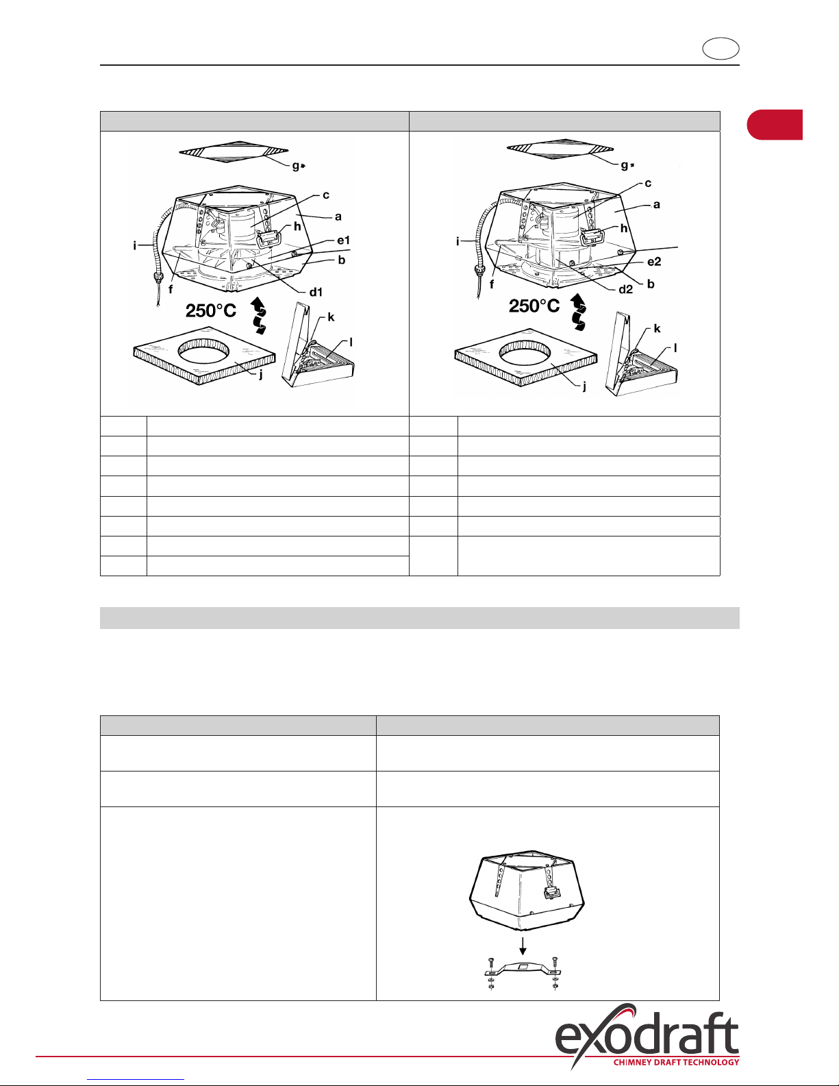
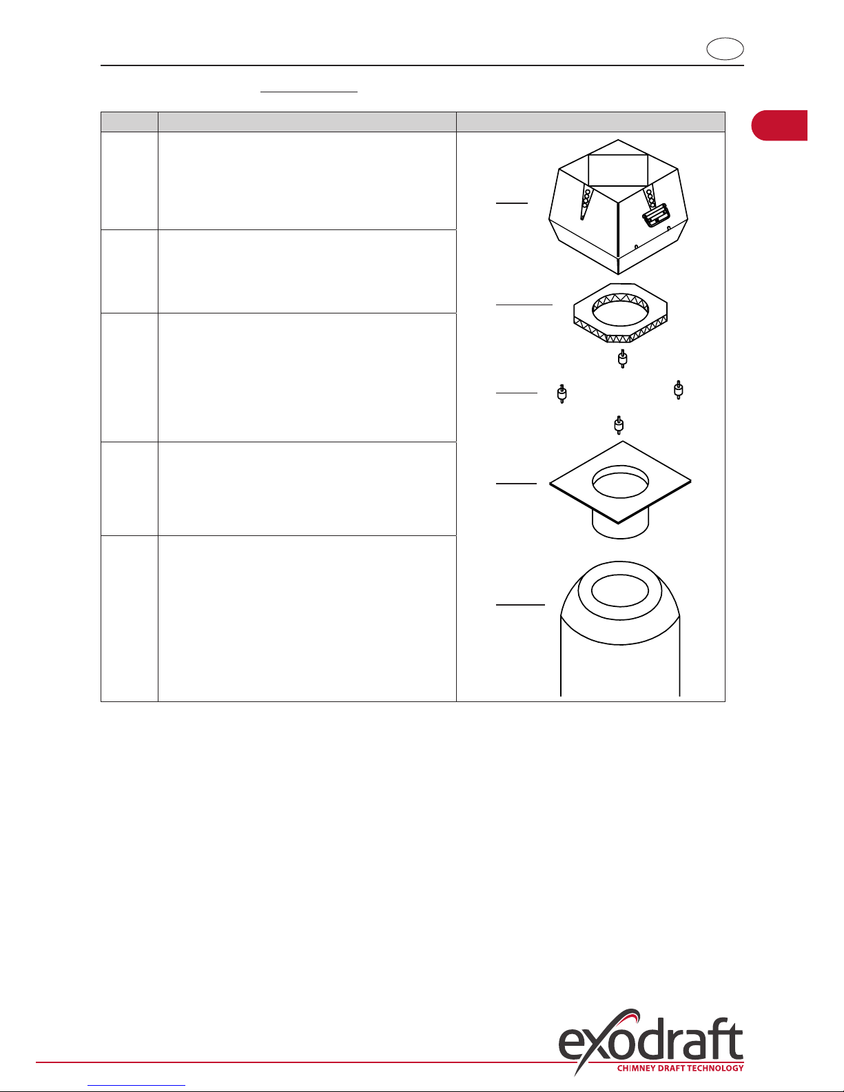
Main components: The RSV has the following main components
RSV009-012-014-016 RSV160-200-250-315-400-450
m
m
m
a Top section g Safety mesh
b Bottom section h Handle
c Motor i Armoured cable and connecting cable
d1 Vane j Mineral wool mat
d2 Centrifugal impeller k Safety wire
e1 Inlet for axial vane l Location bracket, bolt and nuts
e2 Inlet for centrifugal impeller m Screws to fasten top and bottom section
(Alternatively use supplied wing screw, where
conditions allow)
f Hinge
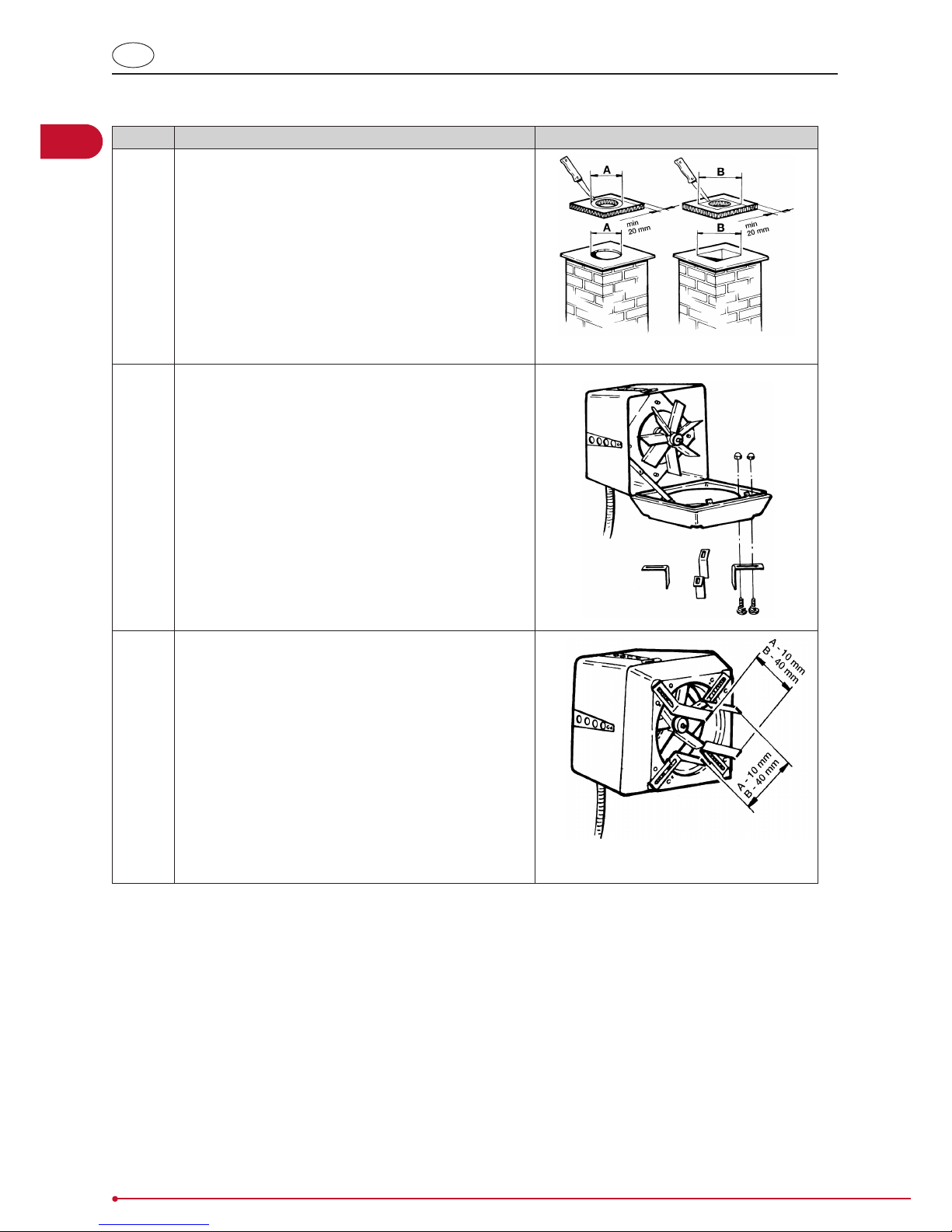
1.2 Installation instructions
The fan is designed to be tted directly on top of brick or steel chimneys, as long as these are stable and level.
Before tting onto a chimney
If ... then ...
the fan is to be mounted onto a brick chimney the chimney must have location brackets – see below
the fan is to be mounted onto a steel chimney a ange is required (supplied as an extra) – see below
the fan is a RSV315, 400 or 450 the impeller is secured with a safety bracket for transporta-
tion.
Remove the transportation safety bracket located near the
impeller and check that the impeller can turn freely.
5
3000113 RSV 2012-10-05
UK
Before tting onto the brickwork of a chimney
Step Action
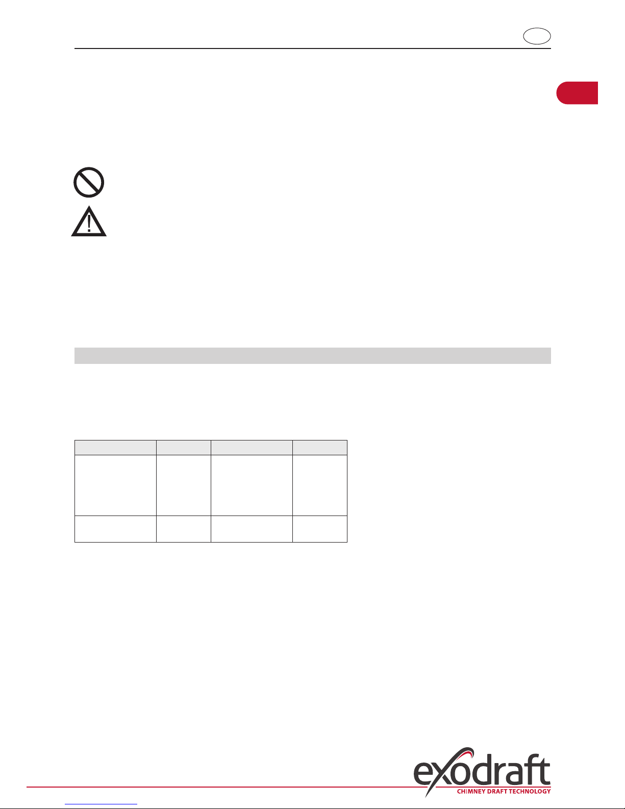
1 Measure the inside diameter of the chimney and cut the
size of the hole in the mineral wool mat accordingly
Note, however, that there must always be a minimum of 20
mm of mat surface at any point around the circumference
of the hole.
If a temperature sensor is to be installed with the chimney,
cut the aluminium foil on the mineral wool mat to make
room for the sensor; this also ensures that the mat sits level
on the chimney.
NB: The side of the mineral wool mat covered in aluminium
foil is to be placed uppermost, i.e. facing the fan.
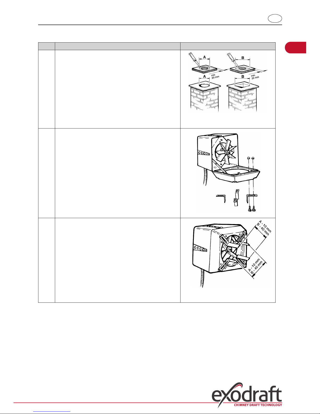
2 Fit the location brackets in the grooves on the underside
of the bottom section and fasten using the nuts and bolts
supplied.
Note that the bolts are to be inserted from beneath the
brackets.
3 Adjust the distance between the location brackets to t
the inside diameter of the chimney, and then tighten the
nuts. Note that there should be a 2-4 mm gap between
the brackets and the chimney so as to avoid transmitting
vibrations from the fan to the chimney.
A and B measurements: please refer to step 1.
The chimney fan can now be tted into place. Place the mineral wool mat on top of the chimney, with the aluminium
foil side up, and place the fan on top.
6
3000113 RSV 2012-10-05
UK
Before tting onto a steel chimney
Step Action
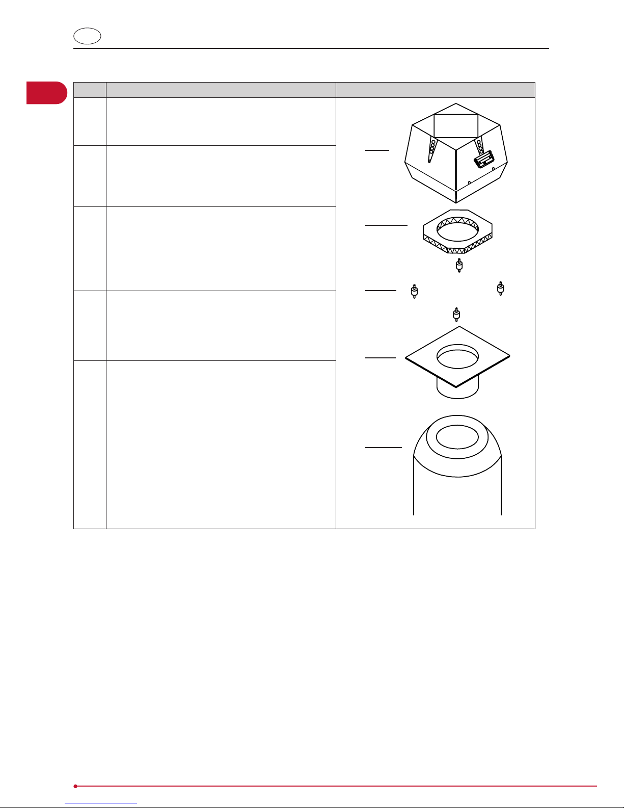
1 A ange (D) (supplied as extra) is used, tted so that the
spigot end sits inside the chimney (E).
A
B
C
D
E
2 Place the mineral wool mat (B) on the ange (D) with
the aluminium foil facing upwards and cut a hole in the
mineral wool mat, the hole being the same diameter as
the ange hole.
3 Cut the corners of the mineral wool mat, so there is
room to t the vibration dampers (C).
If a temperature sensor is to be installed with the chimney fan, cut the aluminium foil on the mineral wool mat
to make room for the sensor; this also ensures that the
mat sits level on the chimney.
4 Fit the ange to the chimney fan, with the use of the
vibration dampers (C).
5 The fan can now be tted onto the chimney.
7
3000113 RSV 2012-10-05
UK
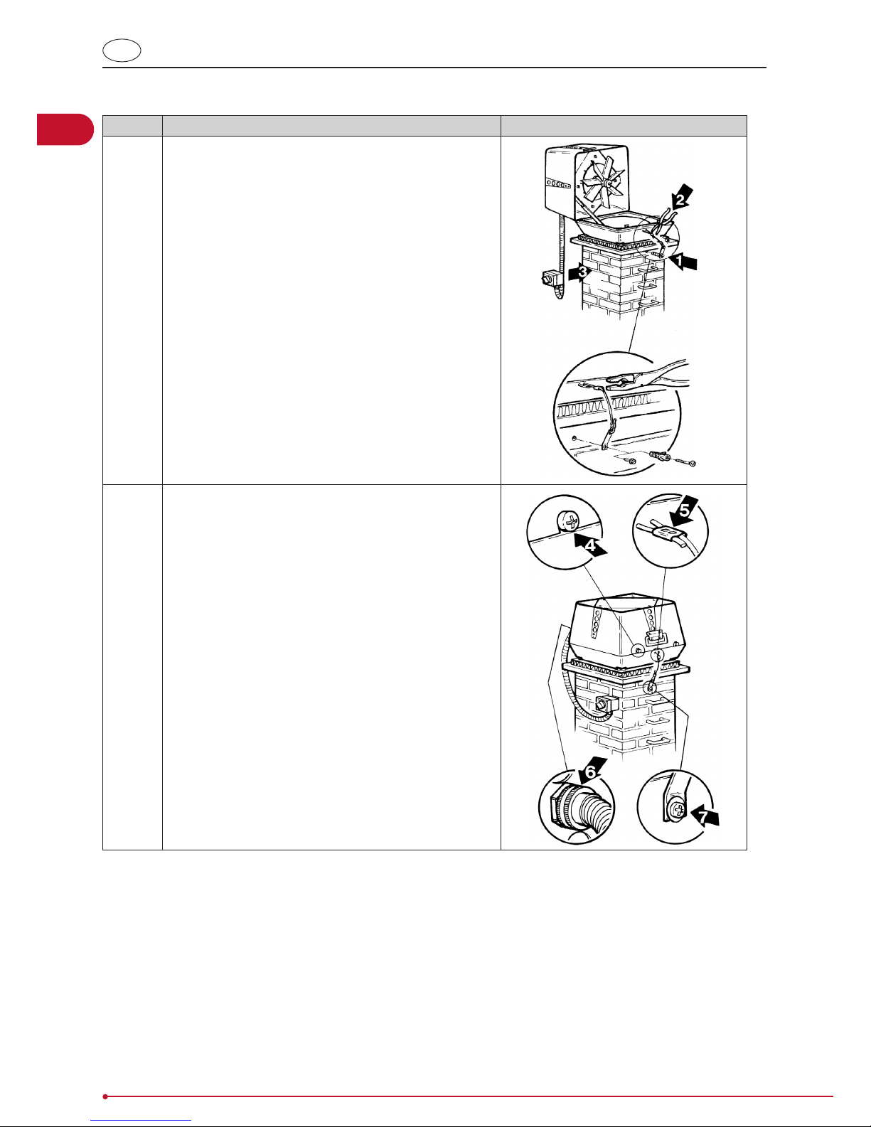
Fitting the chimney fan onto the chimney
Step Action
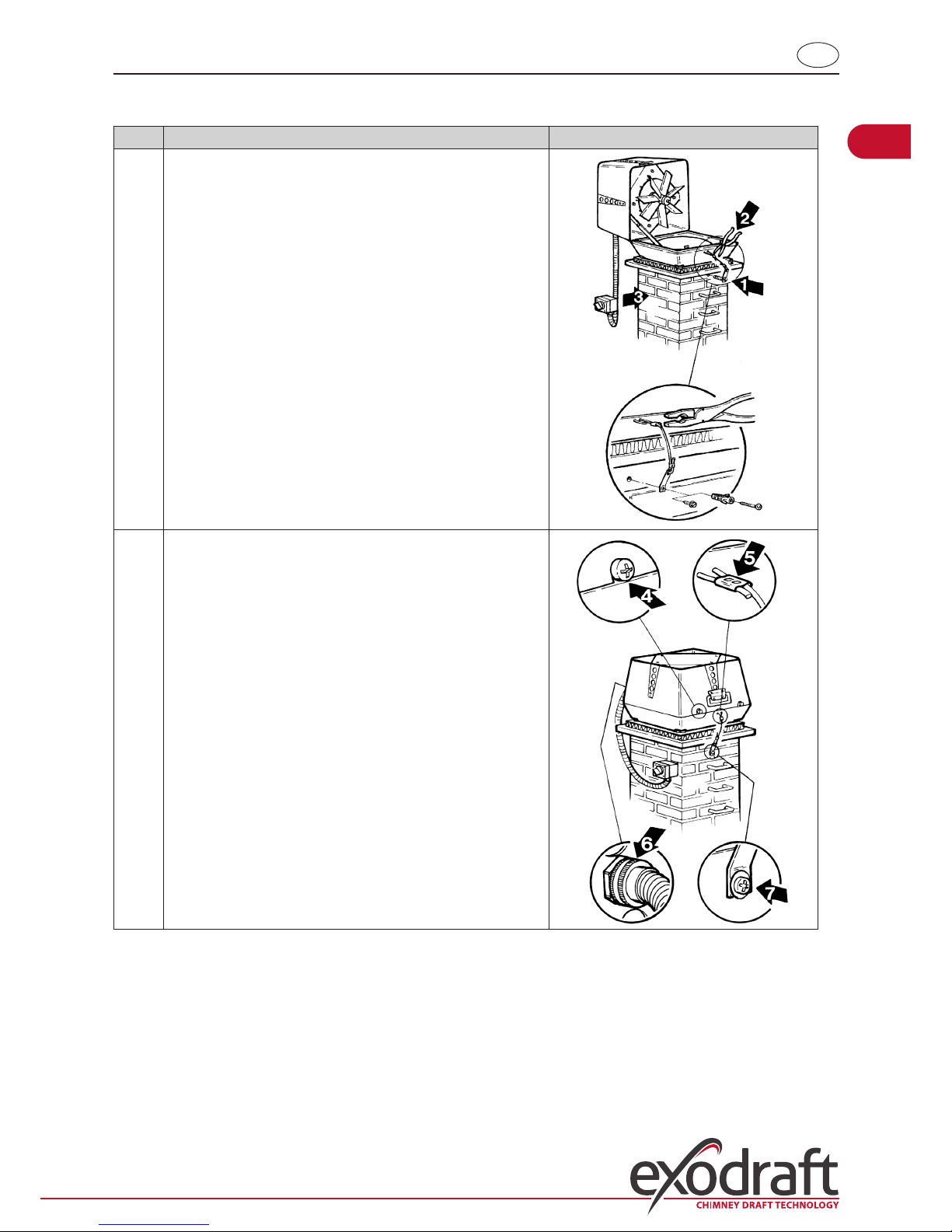
1 Attach the safety wire to the chimney (1). Use the screw and
rawl plug provided in the brickwork of the chimney or the
self-cutting screw if working on a steel chimney. Then t the
wire through the hole in the bottom section and into the
wire clamp.
Gently tighten the safety wire, and crimp (2) the wire clamp
so that the fan is held safely in place when opened for servicing or cleaning purposes.
The isolation switch (supplied as extra) should be tted onto
the side of the chimney (3), so it is easily accessible when
servicing the fan. The armoured cable with connecting cable
should be mounted into the underside of the isolator and up
into the switch through the coupling.
2 Prior to use check that:
• The fan is closed and the fastening screws/wing
screws tightened (4)
• The safety wire is taut and the wire clamp crimped (5)
• The coupling nut on the armoured cable is tightened
(6)
• The safety wire is securely attached to the chimney (7)
• That the user is aware that the fan must always be
switched on whenever the replace or boiler is in use
• The transportation safety bracket has been removed
(RSV315, -400 and -450).
8
3000113 RSV 2012-10-05
UK
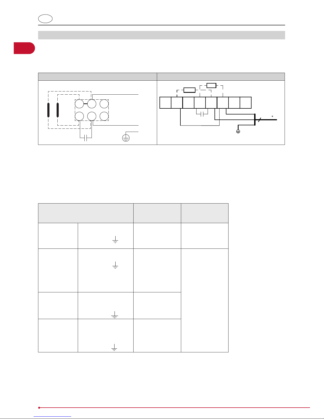
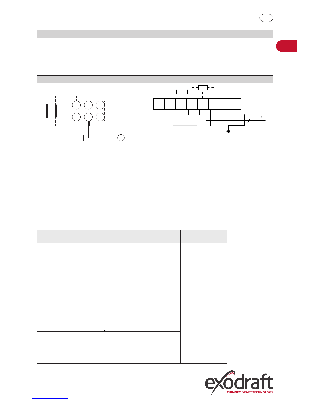
1.3 Wiring
Fan and motor specications are provided on the fan’s type plate. All the single-phased models are adjustable.
Wires are to be connected as per the wiring diagram. For further details, please see guidelines for the exodraft control
units. All exodraft fans require extra safe-guards in accordance with power current regulations.
Any lightning conductor connected to the fan must respect current applicable legislation.
exodraft motor Grundfos motor
Nreg
L
Z2 U1 T2
Z1 U2 T1
MAIN
AUX
N
8
7 6
5 4
3
2
1
AUX
MAIN
L1
N
POWER SUPPLY
1 x 230V ~ 50Hz
3 x 0,75
YEGN
Isolation switch:
In accordance with the provisions of the EU Machinery Directive* a combustion-gas fan
must always have an isolation switch tted. The isolation switch must comply with national wiring standards.
*Please refer to Machine Directive (2006/42/EF/-EEC/-EWG/-CEE) – Appendix 1item 1.6.3 “Separation of the sources of energy
The isolation switch must be ordered separately, as it is not part of the standard exodraft chimney fan delivery.
Connecting cable
and wiring
Variable adjust-
able electronic
regulator
Protection
RSV009-4-1
RSV160-4-1
brown = L
blue = Nreg.
yellow/green =
Yes
The motor can be
blocked.
(impedance-protected)
RSV012-4-1
RSV014-4-1
RSV016-4-1
RSV200-4-1
RSV250-4-1
RSV315-4-1
RSV400-4-1
brown = L
blue = Nreg.
yellow/green =
Yes
The motor requires
overload
protection
RSV250-4-3
RSV315-4-3
RSV400-4-3
brown = L1
blue = L2
black = L3
yellow/green =
No
RSV400-4-2
RSV450-4-2
1 – L1
2 – L2
3 – L3
4 + 5 Thermocal switch
yellow/green=
Yes, by frequency
converter max.
60Hz
9
3000113 RSV 2012-10-05
UK
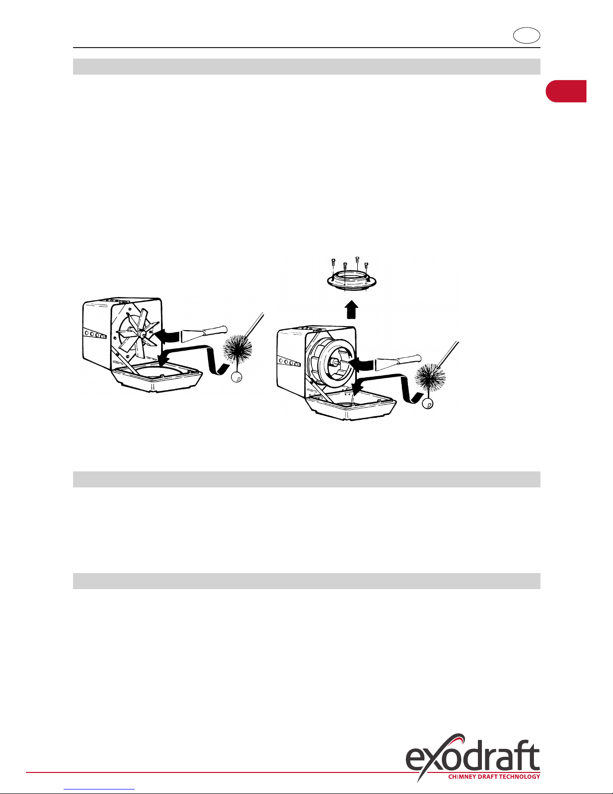
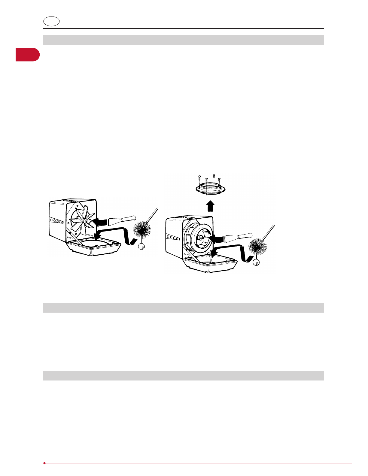
1.4 Service and cleaning
The motor in the RSV fan has special ball bearings that are sealed, lifetime lubricated, and maintenance-free. Any replacement of these bearings should be carried out by qualied professionals.
The fan should be checked and cleaned as required (at least once a year), depending on the fuel being used. Respect
the following procedure:
• Use the isolation switch to switch o the fan. Wait until the fan stops rotating
• Loosen the screw and open the top section of the fan so that it hangs on its hinges and the safety
wire
• Using a scraper or brush, carefully clean the vane / centrifugal impeller
• Check the path taken by the smoke through the top and bottom sections of the fan for soot de-
posits, and clean where necessary with a scraper or brush
• When the fan is open it is also possible to sweep the chimney. In the case of the RSV160-450 it is
recommended that the insert in the bottom section be removed prior to sweeping. This allows
better access to the chimney
• Check that there is free access for fresh air to the motor through the holes in the top section.
Make sure that any weights on the centrifugal impeller are not removed.
RSV009-012-014-016 RSV160-200-250-315-400-450
1.5 Technical specications
The sound level is below 68 dB at a distance greater than ve metres away from the RSV fan when it is correctly tted.
Further information is available in the catalogue.
The standard version of the RSV fan is designed to operate with a maximum ue gas temperature of 250 °C. At higher
temperatures, though maximum 300 °C, the mineral wool mat should be replaced with adjusting screws (type RSD) or
vibration dampers (type SVD.-RS) at the ange. See special guidelines for these parts.
1.6 Warranty
exodraft provides a two-year factory warranty on its ue gas fans, valid from invoice date.
exodraft fans must be installed by competent personnel.
exodraft reserves the right to introduce changes to these guidelines without prior notice.
10
3000113 RSV 2012-10-05
DE
2. DE – Produktinformation
Bitte immer die Montage Anleitung der exodraft Automatik, bevor Montage des Rauchsaugers, lesen.
Der exodraft Rauchsauger vom Typ RSV wird serienmäßig mit Winkeleisen, Panzerschlauch, Sicherungsseil sowie Isolierplatte aus Mineralwolle zwecks vibrationsfreier Montage. Flügelschrauben sind auch dabei, und können verwendet
werden falls die Umstände es erlaubt.
Achtung!
• Die Installation muß von Fachhandwerkern durchgeführt und nach den örtlichen Bestimmungen und
gesetzlichen Vorschriften ausgeführt werden
•
• Um einen Schornsteinbrand zu vermeiden, muß der Schornstein vor der Montage gereinigt werden
• Zur Kühlung des Motors muß der Rauchsauger bei Benutzung der Feuerstelle immer in Betrieb sein!
• Bitte immer die Montage Anleitung der exodraft Automatik, bevor Montage des Rauchsaugers, lesen
• Sofern das exodraft Rauchsauger-System für Feuerstellen mit Festbrennstoen/mehreren Brennstof-
fen entwickelt wurde, stellen Sie bitte sicher, dass die Vorrichtung die Standards nach EN15287-1
erfüllt. Wenn dies nicht gewährleistet werden kann, muss ein Rauchmelder in demselben Raum installiert werden, in dem sich auch das Gerät bendet.
• exodraft empehlt, in der Nähe von oenen Feuerstellen stets einen Rauchmelder anzubringen.
2.1 Produktbeschreibung
Der Rauchsauger ist ein vertikal ausblasender Ventilator aus Gußaluminium.
Er ist in 10 Ausführungen lieferbar: RSV009, 012, 014, 016, 160, 200, 250, 315, 400 und 450. Die Ausführungen RSV009
– 016 sind mit Axialügel aus rostfreiem Stahl ausgerüstet, die Ausführungen RSV160 – 450 verfügen über ein Zentrifugalrad aus Gußaluminium. Beide Ausführungen sind aufklappbar zwecks Wartung und Reinigung.
Gewichte:
Rauchsauger Gewicht Rauchsauger Gewicht
RSV009-4-1
RSV012-4-1
13 kg
17 kg
RSV160-4-1
RSV200-4-1
RSV250-4-1
RSV315-4-1
RSV400-4-1
14 kg
18 kg
27 kg
37 kg
47 kg
RSV014-4-1
RSV016-4-1
24 kg
33 kg
RSV400-4-2
RSV450-4-2
58 kg
67 kg
11
3000113 RSV 2012-10-05
DE
Hauptkomponenten: Der RSV besteht aus folgenden Hauptkomponenten:
RSV009-012-014-016 RSV160-200-250-315-400-450
m
m
m
a Oberteil g Abdeckgitter
b Unterteil h Handgri
c Motor i Panzerschlauch und Anschlußkabel
d1 Axialügel j Mineralwollplatte
d2 Zentrifugalrad k Sicherungsseil
e1 Einlaßteil für Axialügel l Winkeleisen, Schrauben und Muttern
e2 Einlaßteil für Zentrifugalrad m Schrauben oder Flügelschrauben zum abschli-
essen
f Sicherungsbeschlag
2.2 Mechanische Montage
Der Rauchsauger ist für die direkte Montage auf gemauerten Schornsteinen sowie für Stahlschornsteine mit stabilem
und ebenem Abschluß vorgesehen.
Vor der Montage auf dem Schornstein
Bei ... dann ...
Montage des Rauchsaugers auf einem
gemauerten Schornstein…
sind am Rauchsauger Winkeleisen zu montieren – siehe
unten.
Montage des Rauchsaugers auf einem
Stahlschornstein…
ist der Rauchsauger mit einem Flansch (Sonderzubehör)
auszurüsten – siehe unten.
Rauchsauger vom Typ RSV315, 400 oder 450 ... ist die Transportsicherung am Laufrad zu entfernen und zu
kontrollieren, dass sich das Laufrad ungehindert drehen kann.
12
3000113 RSV 2012-10-05
DE
Vor der Montage auf einem gemauerten Schornstein
Schritt Vorgehen
1 Die lichte Weite des Schornsteins messen und ein
entsprechendes Loch in der Mineralwollplatte aus-schneiden. Jedoch müssen mindestens 20 mm Rand stehen
bleiben.
Wenn ein Temperaturfühler zusammen mit dem Rauchsauger montiert wird, ist dafür Platz in der Alufolie der
Mineralwollplatte auszuschneiden, damit der Rauchsauger eben auf der Platte montiert werden kann.
Hinweis: Die Alu-Folie der Mineralwollplatte muß nach
oben gegen den Rauchsauger zeigen.
2 Die Winkeleisen in den Nuten an der Unterseite des
Unterteils montieren und mit Hilfe der mitgelieferten
Schrauben und Muttern befestigen.
Hinweis: Die Schrauben sind von unten zu montieren.
3 Den Abstand zwischen den Winkeleisen der Schorn-
steinweite anpassen und die Muttern anziehen.
Hinweis: Zwischen Winkeleisen und Schornstein muß ein
Abstand von 2 – 4 mm vorhanden sein, damit Vibrationen vom Rauchsauger nicht auf den Schornstein übertragen werden.
Der Rauchsauger ist jetzt bereit für die Montage. Die
Mineralwollplatte jetzt mit der Alu-Folie nach oben auf
den Schornsteinkopf legen und den Rauchsauger darauf
montieren
13
3000113 RSV 2012-10-05
DE
Vor der Montage auf einem Stahlschornstein:
Schritt Vorgehen
1 Für Stahlschornsteine wird ein Flansch (D) benutzt,
der durch Hineinschieben in den Schornstein (E)
montiert wird.
Zunächst wird der Flansch auf dem Rauchsauger
montiert:
A
B
C
D
E
2 Die Mineralwollplatte (B) auf den Flansch (D) mit der
Alufolie nach oben legen und ein Loch entsprechend
der Lichte des Flansches in der Mineralwollplatte
schneiden.
3 Die Ecken der Mineralwollplatte abschneiden, damit
für die Schwingungsdämper (C) Platz wird.
Wenn ein Temperaturfühler zusammen mit dem Rauchsauger montiert wird, ist dafür Platz in der Alufolie
der Mineralwollplatte auszuschneiden, damit der
Rauchsauger eben auf der Platte montiert werden
kann.
4 Den Rauchsauger mit Hilfe der Schwingungs-
dämpfer(C) auf dem Flansch montieren.
5 Der Rauchsauger ist jetzt bereit für die Montage auf
dem Schornstein.
Den Flansch im Schornstein anbringen (E).
14
3000113 RSV 2012-10-05
DE
Befestigen des Rauchsaugers auf dem Schornstein
Schritt Vorgehen
1 Das Sicherungsseil am Schornstein montieren (1). Bei ge-
mauerten Schornsteinen die mitgelieferte Schraube und
den Mauerdübel verwenden und bei Stahlschorn-steinen
selbstschneidende Schrauben verwenden. Anschließend
das Seil durch das Loch im Unterteil führen und im Befestigungsring montieren.
Das Sicherungsseil leicht anziehen und den Befesti-gungsring festklemmen (2), damit der Rauchgas-ventilator beim
Önen zwecks Wartung und Reinigung festgehalten wird.
Den Wartungsschalter (Sonderzubehör) seitlich am Schornsteinkopf befestigen (3). Den Panzerschlauch mit dem
Anschlußkabel von unten durch die Kabelein-führung im
Schalter montieren.
2 Vor Inbetriebnahme kontrollieren, daß:
• der Rauchsauger geschlossen ist und die Schrauben/Flügelschrauben angezogen sind (4),
• das Sicherungsseil gespannt und der Befestigungsring festgeklemmt ist (5),
• die Überwurfmutter des Panzerschlauchs angezogen ist (6),
• das Sicherungsseil am Schornstein angeschraubt ist
(7),
• der Benutzer darüber in Kenntnis gesetzt wurde,
daß der Rauchsauger während der Benutzung der
Feuerstelle/des Kessels stets in Betrieb sein muß,
• die Transportsicherung entfernt ist.
(RSV315,-400 und -450)
15
3000113 RSV 2012-10-05
DE
2.3 Elektrischer Anschluß
Die technischen Daten des Rauchsaugers und des Motors gehen aus den jeweils montierten Typenschildern hervor.
Sämtliche 1-phasigen Modelle sind regelbar.
Der elektrische Anschluß erfolgt gemäß Schaltplan. Ferner wird auf die Anleitung der jeweiligen exodraft-Automatik
verwiesen. Sämtliche Rauchsaugeren sind gegen direkte Berührung zu schützen.
Eine Blitzableitung ist entsprechend den örtlichen gesetzlichen Vorschriften auszuführen.
exodraft Motor Grundfos Motor
Nreg
L
Z2 U1 T2
Z1 U2 T1
MAIN
AUX
N
8
7 6
5 4
3
2
1
AUX
MAIN
L1
N
POWER SUPPLY
1 x 230V ~ 50Hz
3 x 0,75
YEGN
Montage von Wartungs-schaltern:
Die exodraft weist darauf hin, daß die Richtlinie Maschinen *) die Montage eines Wartungsschalters bei der festen
Installation von Rauchsaugeren vorschreibt.
*) Es wird auf die “Richtlinie Maschinen 2006/42/EWG” – Anhang 1 – Nummer 1.6.3 ”Trennung von den Energiequellen”
verwiesen”.
Der Schalter muß:
• abschließbar sein oder ist sichtbar in der Nähe des Rauchsaugers anzuordnen,
• in der Lage sein, sämtliche Pole von der Versorgungsspannung zu unterbrechen – Kontaktabstand mind. 3 mm
bei jedem Pol.
• Maximale Vorsicherung 10Amp.
Der Wartungsschalter ist gesondert zu bestellen, da er nicht von der exodraft-Lieferung umfasst ist.
Anschlußkabel und elektrische
Schaltung
Stufenlos
elektronisch regelbar
Überlastschutz
RSV009-4-1
RSV160-4-1
braun = L
blau = Nreg
gelb/grün =
Ja
Der Motor verträgt
Blockierung
(impedanzgeschützt)
RSV012-4-1
RSV014-4-1
RSV016-4-1
RSV200-4-1
RSV250-4-1
RSV315-4-1
RSV400-4-1
braun = L
blau = Nreg
gelb/grün =
Ja
Überlastschutz des
Motors erforderlich
RSV250-4-3
RSV315-4-3
RSV400-4-3
braun = L1
blau = L2
schwarz = L3
gelb/grün =
Nein
RSV400-4-2
RSV450-4-2
1 – L1
2 – L2
3 – L3
4 + 5 Termosicherung –
gelb/grün=
Ja, mit Frequenz-umformer max. 60Hz
16
3000113 RSV 2012-10-05
DE
2.4 Wartung und Reinigung
Der Motor des exodraft Rauchsaugers RSV ist mit geschlossenen, wartungs-freien Spezialkugellagern ausgerüstet. Ein
eventueller Austausch der Lager darf nur von Personen mit entsprechenden Fachkennt-nissen vorgenommen werden.
Kontrolle und eventuelle Reinigung des Rauchsaugers ist mind. 1 Mal jährlich (je nach Art des Brennstos) wie folgt
vorzunehmen:
• Den Rauchsauger am Wartungsschalter abschalten; warten bis der Ventilator völlig still steht.
• Die Schrauben lösen und das Oberteil nach hinten aufklappen, wo es vom Sicherungsbeschlag und vom Sicher-
ungsseil festgehalten wird.
• Den Axialügel / das Zentrifugalrad vorsichtig mit einem Spachtel oder einer Bürste reinigen.
• Den Rauchweg durch Ober- und Unterteil auf Rußbildung kontrollieren und mit einem Spachtel oder einer Bür-
ste reinigen.
• Während der Rauchsauger geönet ist, ist gleichzeitig Zugang zum Reinigen des Schornsteins. Bei RSV160-450
ist es zweckdienlich, das Einlaßteil im Unterteil zu demontieren. Dadurch wird der Zugang zum Schornstein besser.
• Überprüfen, daß die Kühlluft durch die Löcher im Oberteil freien Zugang zum Motor hat.
• Vibrationen im Rauchsauger können von einer Unwucht aufgrund eines ver-schmutzten Axialügels / Zentrifu-
galrades herrühren, und die Reinigung ist zu wieder-holen. Eventuelle Auswuchtungsgewichte am Zentrifugalrad dürfen nicht entfernt werden.
RSV009-012-014-016 RSV160-200-250-315-400-450
2.5 Technische Daten
Der an die Umgebung abgegebene Schallpegel liegt bei einem Abstand zum Rauchsauger von mehr als 5 Metern unter
68 dB(A). Dies gilt bei korrekt montiertem RSV. (Im übrigen wird auf die Daten im Prospekt verwiesen.)
Der RSV ist in Standardausführung für eine maximale Rauchgastemperatur von 250 °C konstruiert. Bei höheren Temperaturen, max. 300 °C, ist der Rauchsauger statt der Mineralwollplatte mit Einstellschrauben vom Typ RSD oder
Schwingungsdämpfern vom Typ SVD-RS in Verbindung mit einem Flansch auszurüsten. Siehe gesonderte Anleitung.
2.6 Garantie
exodraft leistet eine 2 jährige Werksgarantie auf den Rauchsauger, ab Rech-nungsdatum.
Die Montage ist von Personen mit entsprechenden Fachkenntnissen auszuführen.
exodraft behält sich das Recht auf Änderungen ohne vorherige Ankündigung vor.

17
3000113 RSV 2012-10-05
DK
3. DK – Produktinformation
exodraft røgsuger type RSV leveres standard med vinkelben, panserslange, sikkerhedswire samt mineraluldsplade som
pakning for vibrationsfri drift. (Desuden er vedlagt vingeskruer, der kan monteres, hvis forholdene tillader det.)
Dårlige fyringsvaner kan resultere i problemer med sod, skorstensbrand, m.m. som kan skade røgsugeren. Se vores råd
om at fyre rigtigt på www.exodraft.dk.
Advarsel!
• Installationen skal udføres af kompetent personale i overensstemmelse med gældende love og regler
•
• Undgå skorstensbrand – Fej skorstenen inden montage
• Røgsugeren skal altid være i drift ved anvendelse af ildstedet
• Læs altid installationsvejledningen for automatikken, før røgsugeren installeres
• Er exodraft røgsugeren en del af brændefyrede installationer skal det sikres at kravene i EN15287-1 er
overholdt. Hvis dette ikke kan opnås skal der monteres en røgalarm i samme rum som brændselsenheden
• exodraft vil altid anbefale opsætning af en røgalarm når en
brændefyret pejs er i brug.
3.1 Konstruktion og design
Røgsugeren er en ventilator konstrueret til vertikalt afkast og udført i støbt aluminium. Den leveres i ti størrelser:
RSV009, 012, 014, 016, 160, 200, 250, 315, 400 og 450.
RSV009 – 016 har aksialvinge af rustfrit stål og RSV160 – 450 har centrifugalhjul i støbt aluminium. Begge udførelser er
oplukkelige for service og rengøring.
Vægt:
Røgsuger Vægt Røgsuger Vægt
RSV009-4-1
RSV012-4-1
13 kg
17 kg
RSV160-4-1
RSV200-4-1
RSV250-4-1
RSV315-4-1
RSV400-4-1
14 kg
18 kg
27 kg
37 kg
47 kg
RSV014-4-1
RSV016-4-1
24 kg
33 kg
RSV400-4-2
RSV450-4-2
58 kg
67 kg

18
3000113 RSV 2012-10-05
DK
Hovedkomponenter: RSV består af følgende hovedkomponenter:
RSV009-012-014-016 RSV160-200-250-315-400-450
m
m
m
a Toppart g Net
b Bundpart h Håndtag
c Motor i Panserslange og tilslutningskabel
d1 Aksialvinge j Mineraluldsplade
d2 Centrifugalhjul k Sikkerhedswire
e1 Aksialindsats l Vinkelben, bolte og møtrikker
e2 Centrifugalindsats m Skruer eller vingeskruer til at lukke røgsugeren
med.
f Sikringsbeslag
3.2 Mekanisk installation
Røgsugeren er beregnet til direkte montage på murede skorstene samt stålskorstene med stabil og plan afslutning.
Før montage på skorstenen
Hvis ... så ...
røgsugeren skal monteres på en
muret skorsten ...
skal røgsugeren forsynes med vinkelben – se nedenfor
røgsugeren skal monteres på en
stålskorsten ...
skal røgsugeren forsynes med en ange (ekstra tilbehør) – se
nedenfor
røgsugeren er en RSV315, 400 eller 450 ... skal transportsikringen ved løbehjulet ernes, og det kontrol-
leres, at løbehjulet kan løbe uhindret rundt.
Før montage på muret skorsten

19
3000113 RSV 2012-10-05
DK
Trin Handling
1 Skorstenens lysning måles, og der laves et tilsvarende hul i
mineraluldspladen. Hullet må dog aldrig gøres større, end
at der er minimum 20 mm anlægsade tilbage.
Hvis en temperaturføler installeres sammen med røgsugeren, skal der skæres plads til den i alufolien på mineraluldsmåtten for at røgsugeren kan stå plant på måtten.
Bemærk: Alu-folien på mineraluldspladen skal vende op
mod røgsugeren.
2 Vinkelbenene monteres i sporene på undersiden af bære-
pladen og fastgøres ved hjælp af de medleverede bolte og
møtrikker.
Bemærk, at boltene skal monteres nedefra.
3 Afstanden mellem vinkelbenene justeres i henhold til skor-
stenens lysning, og møtrikkerne fastspændes. Bemærk, at
der skal være 2 – 4 mm luft imellem vinkelben og skorsten,
således at der ikke overføres vibrationer fra røgsuger til
skorsten.
Røgsugeren er nu klar til montage. Mineraluldspladen
lægges på toppen af skorstenen med alufolien opad, og
røgsugeren placeres ovenpå.

20
3000113 RSV 2012-10-05
DK
Før montage på stålskorsten:
Trin Handling
1 Til stålskorstene anvendes en ange (D), der monteres
ved at studsen sættes ned i skorstenen (E).
Først monteres angen på røgsugeren:
A
B
C
D
E
2 Placer mineraluldsmåtten (B) på angen (D) med alufo-
lien (C) opad og skær hul i mineraluldsmåtten svarende
til angens lysning
3 Skær hjørnerne af mineraluldsmåtten, så der bliver
plads til svingningsdæmperne (C)
Hvis en temperaturføler installeres sammen med
røgsugeren, skal der skæres plads til den i alufolien på
mineraluldsmåtten for at røgsugeren kan stå plant på
måtten.
4 Monter røgsugeren på angen ved hjælp af svingnings-
dæmperne
5 Røgsugeren er nu klar til montage på skorstenen. Placer
angen i skorstenen.

21
3000113 RSV 2012-10-05
DK
Sådan fastgøres røgsugeren på skorstenen
Trin Handling
1 Sikkerhedswiren fastgøres på skorstenen (1). Den medle-
verede skrue og rawlplug anvendes til muret skorsten og
selvskærende skrue til stålskorsten. Herefter monteres wiren
igennem hullet i bærepladen og ind i wirelåsen.
Sikkerhedswiren strammes let og wirelåsen klemmes/crimpes (2), således at røgsugeren fastholdes ved åbning for
service og rengøring.
Reparationsafbryderen (ekstra tilbehør) monteres på siden af
skorstenen (3), så den er let tilgængelig ved service. Panserslangen med tilslutningskabel monteres nedefra og op i
afbryderen gennem forskruningen.
2 Inden ibrugtagning kontrolleres at:
• Røgsugeren er lukket, og skruerne/vingeskruerne er
fastspændt (4).
• Sikkerhedswiren er strammet, og wirelåsen er klemt/
crimpet (5).
• Omløberen på panserslangen er fastspændt (6).
• Sikkerhedswiren er fastspændt til skorstenen (7).
• Brugeren er bekendt med, at røgsugeren altid skal
være i drift ved anvendelse af ildstedet/kedlen.
• Transportsikringen er ernet. (RSV315, -400 og -450)

22
3000113 RSV 2012-10-05
DK
3.3 El-tilslutning
Røgsuger- og motorspecikationer fremgår af de monterede typeskilte. Alle 1-fasede modeller er regulerbare.
El-tilslutningen foretages iht. el-diagrammet. I øvrigt henvises til vejledningerne for exodraft automatik. Alle røgsugere
kræver ekstrabeskyttelse iht. stærkstrøms-bekendtgørelsen.
Lynaedning skal ske iht. gældende love og bestemmelser.
exodraft motor Grundfos motor
Nreg
L
Z2 U1 T2
Z1 U2 T1
MAIN
AUX
N
8
7 6
5 4
3
2
1
AUX
MAIN
L1
N
POWER SUPPLY
1 x 230V ~ 50Hz
3 x 0,75
YEGN
Opsætning af reparationsafbryder:
exodraft A/S gør opmærksom på, at der i henhold til Maskindirektivet*) skal opsættes en reparationsafbryder i den
faste installation af røgsugeren..
*) Der henvises til “Maskindirektivet, 2006/42/EF” – bilag 1 – pkt. 1.6.3 “Adskillelse af energikilderne”.
Afbryderen skal:
• være aåselig, eller placeres synligt i nærheden af røgsugeren,
• kunne afbryde alle poler fra forsyningsspændingen – kontaktafstand min. 3 mm i hver pol.
Reparationsafbryderen skal bestilles særskilt, da den ikke er en del af exodraft-leverancen.
Tilslutningskabel
og elkobling
Trinløs
elektronisk regulerbar
Beskyttelse
RSV009-4-1
RSV160-4-1
brun = L
blå = Nreg
gul/grøn =
Ja
Motoren tåler
blokering
(impedansbeskyttet)
RSV012-4-1
RSV014-4-1
RSV016-4-1
RSV200-4-1
RSV250-4-1
RSV315-4-1
RSV400-4-1
brun = L
blå = Nreg
gul/grøn =
Ja
Motoren skal
overbelastningsbeskyttes
RSV250-4-3
RSV315-4-3
RSV400-4-3
brun = L1
blå = L2
sort = L3
gul/grøn =
Nej
RSV400-4-2
RSV450-4-2
1 – L1
2 – L2
3 – L3
4 + 5 Termosikring
- gul/grøn=
Ja, via frekvens-omformer max. 60Hz

23
3000113 RSV 2012-10-05
DK
3.4 Service og rengøring
Motoren i exodraft røgsuger RSV har engangs-smurte lukkede specialkuglelejer og er vedligeholdelsesfri. Eventuel
udskiftning af lejer bør kun udføres af personer med fagekspertise.
Kontrol og evt. rengøring af røgsugeren foretages efter behov (min. 1 gang årligt), afhængig af brændslet, på følgende
måde:
• Røgsugeren stoppes på reparationsafbryderen. Der ventes til rotationen er ophørt.
• Skruerne løsnes, og overparten løftes bagover, hvor den fastholdes af hængsler og sikkerhedswire.
• Aksialvingen / centrifugalhjulet rengøres forsigtigt med spartel eller børste.
• Røgvejen igennem top- og bundpart kontrolleres for soddannelse og rengøres med spartel eller børste.
• Når røgsugeren er åben, er der samtidig adgang for fejning af skorstenen. På RSV160-450 kan det være formåls-
tjenligt at demontere indsatsen i underparten. Herved opnås større adgang til skorstenen.
• Kontroller, at køleluften har fri adgang til motoren igennem hullerne i topparten.
• Hvis der forekommer rystelser i røgsugeren, kan det skyldes ubalance som følge af tilsmudset aksialvinge/ centri-
fugalhjul og rengøringen gentages. Evt. afvejnings-klodser på centrifugalhjulet må ikke ernes
RSV009-012-014-016 RSV160-200-250-315-400-450
3.5 Tekniske data
Lydniveauet til omgivelserne er under 68 dB(A), når afstanden til røgsugeren er større end 5 meter. Dette gælder, når
RSV er monteret korrekt. (I øvrigt henvises til katalog-data.)
RSV er i standardudførelse konstrueret til max. 250 °C røgtemperatur. Ved højere temperaturer, max. 300 °C, skal røgsugeren, i stedet for mineraluldspade, forsynes med stilleskruer type RSD eller svingningsdæmpere type SVD-RS i forbindelse med ange. Se specialvejledning.
3.6 Garanti
exodraft yder 2 års fabriksgaranti på røgsugeren fra fakturadato.
Installationen skal foretages af kompetente personer.
exodraft forbeholder sig ret til ændringer uden forudgående varsel.

24
3000113 RSV 2012-10-05
NO
4. NO – Produktinformasjon
exodraft røyksuger type RSV leveres standard med vinkelben, panserslange, sikkerhetsvaier samt mineralullplate som
pakning for vibrasjonsfri drift. (Dessuten er det vedlagt vingeskruer, som kan monteres hvis forholdene tillater det).
Advarsel!
• Alle installasjoner må utføres av faglært personell i samsvar med gjeldende nasjonale regler og forskrifter
•
• Unngå skorsteinsbrann – fei skorsteinen før montering.
• Røksugeren må alltid være i drift når ildstedet er i bruk.
• Les alltid automatikkens installasjonsveiledning før røksugeren
installeres.
• Hvis exodraft røyksuger er beregnet for installasjoner med fast brensel/multibrensel, er det viktig å
sikre at utformingen oppfyller kravene i EN15287-1. Hvis dette ikke er tilfelle, må det installeres en
røykvarsler i samme rom som apparatet.
• exodraft anbefaler at det alltid benyttes røykvarsler for installasjoner med fast brensel og åpen ild.
4.1 Konstruksjon
Røyksugeren er en vifte konstruert til vertikalt avkast og utført i støpt aluminium. Den leveres i ti størrelser: RSV009,
012, 014, 016, 160, 200, 250, 315, 400 og 450. RSV009 – 016 har aksialvinge av rustfritt stål, og RSV160 – 450 har sentrifugalhjul i støpt aluminium. Begge utførelser kan åpnes for service og rengjøring.
RSV består av følgende hovedkomponenter:
RSV009-012-014-016 RSV160-200-250-315-400-450
m
m
m
a Topp del g Gitter
b Bunn del h Håndtak
c Motor i Panserslange og tilkoblingskabel
d1 Aksialvinge j Mineralullplate
d2 Sentrifugalhjul k Sikkerhetsvaier
e1 Aksialinnsats l Vinkelben, skruer og muttere
e2 Sentrifugalinnsats m Skruer eller vingeskruer til å lukke
røyksugeren med.
f Sikringsbeslag
Røyksuger Vekt Røyksuger Vekt
RSV009-4-1
RSV012-4-1
13 kg
17 kg
RSV160-4-1
RSV200-4-1
RSV250-4-1
RSV315-4-1
RSV400-4-1
14 kg
18 kg
27 kg
37 kg
47 kg
RSV014-4-1
RSV016-4-1
24 kg
33 kg
RSV400-4-2
RSV450-4-2
58 kg
67 kg

25
3000113 RSV 2012-10-05
NO
4.2 Mekanisk installasjon
Røyksugeren er beregnet til direkte montering på murte skorsteiner og stålskorsteiner med stabil og plan avslutning.
Før montering på skorsteinen
Hvis ... Så ...
røyksugeren skal monteres på en
murt skorstein ...
skal røyksugeren forsynes med vinkelben – se nedenfor
røyksugeren skal monteres på en
stålskorstein ...
skal røyksugeren forsynes med en ens (ekstra tilbehør)
– se nedenfor
røyksugeren er en RSV315, 400 eller 450 ... skal transportsikringen ved sentrifugalhjulet ernes, og det
kontrolleres at hjulet kan dreie fritt rundt.
Før montering på murt skorstein
Trinn Handling
1 Mål skorsteinens lysmål og lag et tilsvarende hull i minera-
lullplaten. Hullet må imidlertid aldri gjøres større enn at det
er minimum 20 mm anleggsate tilbake.
Hvis det installeres en temperaturføler sammen med røyksugeren, skal det skjæres plass til denne i aluminiumsfolien
på mineralullplaten, slik at røyksugeren kan stå plant på
platen.
Merk: Aluminiumsfolien på mineralullplaten skal vende
opp mot røyksugeren
2 Vinkelbena monteres i sporene på undersiden av bærepla-
ten og gjøres fast ved hjelp av skruene og mutrene som
følger med.
Merk at skruene skal monteres nedenfra.
3 Juster avstanden mellom vinkelbena i henhold til skorstei-
nens lysmål og trekk til mutrene. Merk at det skal være 2 –
4 mm klaring mellom vinkelben og skorstein slik at det ikke
overføres vibrasjoner fra røyksugeren til skorsteinen.
Røyksugeren er nå klar til montering. Legg mineralullplaten
på toppen av skorsteinen med aluminiumsfolien opp og
plasser røyksugeren oppå denne.

26
3000113 RSV 2012-10-05
NO
Før montering på stålskorstein:
Trinn Handling
1 På stålskorsteiner brukes en ens (D) som monteres, slik
at stussen settes ned i skorsteinen (E).
Først monteres ensen på røyksugeren:
A
B
C
D
E
2 Plasser mineralullplaten (B) på ensen (D) med alumi-
niumsfolien opp og skjær et hull i mineralullplaten som
svarer til ensens diameter.
3 Skjær hjørnene av mineralullplaten, slik at det blir plass
til vibrasjonsdemperne (C).
Hvis det installeres en temperaturføler sammen med
røyksugeren, skal det skjæres plass til denne i aluminiumsfolien på mineralullplaten, slik at røyksugeren kan
stå plant på platen.
4 Monter røyksugeren på ensen ved hjelp av
vibrasjonsdemperne (C).
5 Røyksugeren er da klar til montering på skorsteinen.
Plasser ensen i skorsteinen (E).

27
3000113 RSV 2012-10-05
NO
Slik festes røyksugeren på skorsteinen
Trinn Handling
1 Gjør sikkerhetsvaieren fast til skorsteinen (1). Bruk skruen og
murpluggen som følger med, til murt skorstein og selvskjærende skrue i stålskorstein. Monter heretter vaieren gjennom
hullet i bæreplaten og inn i vaierlåsen.
Stram sikkerhetsvaieren lett og klem/krymp vaierlåsen (2)
sammen slik at røyksugeren holdes fast ved åpning for service og rengjøring.
Monter servicebryteren (ekstra tilbehør) på siden av skorsteinen (3) slik at den er lett tilgjengelig ved service. Panserslangen med tilkoblingskabel monteres nedenfra og opp i
bryteren gjennom forskruningen.
2 Før røyksugeren tas i bruk, må det kontrolleres at:
• Røyksugeren er stengt, og skruen/vingeskruen er
trukket til (4).
• Sikkerhetsvaieren er strammet opp, og vaierlåsen er
klemt/krympet (5).
• Koppmutteren på panserslangen er trukket til (6).
• Sikkerhetsvaieren er gjort fast til skorsteinen (7).
• Brukeren er kjent med at røyksugeren alltid må være i
drift når ildstedet/kjelen er i bruk.
• Transportsikringen er ernet. (RSV315, -400 og -450)

28
3000113 RSV 2012-10-05
NO
4.3 Elektrisk tilkobling
Røyksuger- og motorspesikasjoner fremgår av typeskiltene som er montert. Alle 1-fasede modeller er regulerbare.
Elektrisk tilkobling foretas iht. strømdiagrammet. For øvrig henvises til veiledningene for exodraft automatikk. Alle
røyksugere krever ekstrabeskyttelse iht. sterkstrømsreglementet.
Lynavledning skal utføres iht. gjeldende forskrifter.
exodraft motor Grundfos motor
Nreg
L
Z2 U1 T2
Z1 U2 T1
MAIN
AUX
N
8
7 6
5 4
3
2
1
AUX
MAIN
L1
N
3 x 0,75
YEGN
Montering av servicebryter:
exodraft gjør oppmerksom på at det i henhold til Maskindirektivet*) skal monteres en servicebryter i den faste instal-
lasjonen av røyksugere
*) Det henvises til “Maskindirektivet 2006/42/EF” – vedlegg 1 – pkt. 1.6.3 ”Atskillelse av energikildene”
Bryteren skal:
• være låsbar eller plasseres synlig i nærheten av røyksugeren.
• kunne bryte alle poler fra matespenningen – kontaktavstand min. 3 mm i hver pol.
Servicebryteren må bestilles separat, da den ikke er en del av exodraft-leveransen.
Tilkoblingskabel
og elektrisk tilkobling
Trinnløs
elektronisk
regulerbar
Beskyttelse
RSV009-4-1
RSV160-4-1
brun = L
blå = Nreg
gul/grønn =
Ja
Motoren tåler blokkering
(impedans-beskyttet)
RSV012-4-1
RSV014-4-1
RSV016-4-1
RSV200-4-1
RSV250-4-1
RSV315-4-1
RSV400-4-1
brun = L
blå = Nreg
gul/grønn =
Ja
Motoren skal
overbelastningsbeskyttes
RSV250-4-3
RSV315-4-3
RSV400-4-3
brun = L1
blå = L2
svart = L3
gul/grønn =
Nej
RSV400-4-2
RSV450-4-2
1 – L1
2 – L2
3 – L3
4 + 5 Termosikring
- gul/grønn =
Ja, via frekvensomformer maks. 60 Hz

29
3000113 RSV 2012-10-05
NO
4.4 Service og rengjøring
Motoren i exodraft røyksuger RSV har livstidssmurte, lukkede spesialkulelagre og er vedlikeholdsfri. Eventuell utskifting
av lagre bør bare utføres av fagekspertise.
Kontroll og ev. rengjøring av røyksugeren foretas etter behov (min. 1 gang årlig), avhengig av brenslet, på følgende
måte:
• Stopp røyksugeren med servicebryteren. Vent til rotasjonen er opphørt.
• Løs skruene og løft overdelen bakover. Den holdes fast av hengsler og sikkerhets-vaieren.
• Rengjør aksialvingen / sentrifugalhjulet forsiktig med sparkel eller børste.
• Kontroller røykveien opp gjennom topp- og bunndel for sotdanning og gjør rent med børste.
• Når røyksugeren er åpen, er det samtidig adgang til å feie skorsteinen. På RSV160-450 kan det
være formålstjenlig å demontere innsatsen i underdelen. På den måten oppnås større adgang til
skorsteinen.
• Kontroller at kjøleluften har fri adgang til motoren gjennom hullene i toppdelen.
• Hvis det forekommer vibrasjoner i røyksugeren, kan det skyldes ubalanse som følge av urenhe-
ter på aksialvinge / sentrifugalhjul, og rengjøringen må da gjentas. Ev. avbalanseringsklosser på
sentrifugalhjulet må ikke ernes.
RSV009-012-014-016 RSV160-200-250-315-400-450
4.5 Tekniske data
Lydnivået til omgivelsene er under 68 dB(A) når avstanden til røyksugeren er større enn 5 meter. Dette gjelder når RSV
er montert korrekt. (For øvrig henvises til katalogdata.)
RSV er i standardutførelsen konstruert til maks. 250 °C røyktemperatur. Ved høyere temperaturer, maks. 300 °C, må
røyksugeren, i stedet for mineralullplate, forsynes med stilleskruer type RSD eller vibrasjonsdempere type SVD-RS i
forbindelse med ensen. Se spesialveiledning.
4.6 Garanti
exodraft yter 2 års fabrikkgaranti på røyksugeren fra fakturadato.
Installasjonen må foretas av kompetente personer.
exodraft forbeholder seg rett til endringer uten forutgående varsel.

30
3000113 RSV 2012-10-05
SE
5. SE – Produktbeskrivning
exodraft rökgasäkt typ RSV levereras som standard med vinkelben, pansarslang, förankringslina samt mineralullsplat-
ta som packning för vibrationsfri drift. Dessutom medföljer vingskruvar, som kan monteras om förhållandena så tillåter.
Varning!
• Installationen skall utföras av kompetenta personer med hänsyn till gällande lagar og bestämmelser
•
• Undvik skorstensbrand. Sota skorstenen före montage.
• Rökgasäkten skall alltid vara i drift när eldstaden används.
• Läs alltid installationsbeskrivningen för styrenheten innan rökgasäkten installeras.
• Om exodraft rökgasäkt används till eldstäder för fast bränsle eller erbränsle, kontrollera att instal-
lationen uppfyller kraven enligt EN15287-1. Om detta inte är möjligt bör en brandvarnare installeras i
samma rum som anläggningen.
• exodraft rekommenderar att man alltid har en brandvarnare installerat där eldstäder som använder
fast bränsle är placerade.
5.1 Konstruktion
Rökgasäkten är en ventilationsäkt med vertikal avluft, tillverkad av gjuten aluminium. Den levereras i 10 storlekar:
RSV009, 012, 014, 016, 160, 200, 250, 315, 400 och 450.
RSV009 – 016 har axialhjul av rostfritt stål och RSV160 – 450 har radialhjul av gjuten aluminium. Båda modellerna kan
öppnas för service och rengöring.
Vikt:
Rökgasäkt Vikt Rökgasäkt Vikt
RSV009-4-1
RSV012-4-1
13 kg
17 kg
RSV160-4-1
RSV200-4-1
RSV250-4-1
RSV315-4-1
RSV400-4-1
14 kg
18 kg
27 kg
37 kg
47 kg
RSV014-4-1
RSV016-4-1
24 kg
33 kg
RSV400-4-2
RSV450-4-2
58 kg
67 kg

31
3000113 RSV 2012-10-05
SE
Huvudkomponenter: RSV består av följande huvudkomponenter:
RSV009-012-014-016 RSV160-200-250-315-400-450
m
m
m
a Överdel g Nät
b Bottendel h Handtag
c Motor i Pansarslang och anslutningskabel
d1 Axialhjul j Mineralullsplatta
d2 Radialhjul k Säkerhetswire
e1 Fläktinlopp l Vinkelben, bultar och muttrar
e2 Radialinsats m Skruvar eller vingskruvar att låsa rökgasäkten
med.
f Säkringsbeslag
5.2 Mekanisk installation
Rökgasäkten är avsedd för direkt montage på murade skorstenar samt på stålskorstenar med plan och stabil yta.
Före montering på skorsten
Om ... så ...
rökgasäkten ska monteras på en murad skorsten ...
ska rökgasäkten förses med vinkelben – se nedan.
rökgasäkten ska monteras på en
stålskorsten ...
ska rökgasäkten förses med en äns (extra tillbehör) – se
nedan.
rökgasäkten är en RSV315, 400 eller 450 ... ska transportsäkringen vid löphjulet tas bort, och man ska
kontrollera att löphjulet kan rotera fritt.

32
3000113 RSV 2012-10-05
SE
Före montering på murad skorsten
Steg Åtgärd
1 Skorstenens öppning mäts och ett motsvarande hål görs i
mineralullsplattan. Hålet får dock aldrig göras större än att
anläggsytan är minst 20 mm bred.
Om en temperaturgivare installeras med rökgasäkten ska
man skära upp plats för den i aluminiumfolien på mineralullsmattan, så att rökgasäkten kan stå plant på mattan.
Obs! Aluminiumfolien på mineralullsplattan skall vara vänd
uppåt, mot rökgasäkten.
2 Vinkelbenen monteras i spåren på undersidan av plattan
och sätts fast med hjälp av de medlevererade bultarna och
muttrarna. Observera att bultarna skall monteras underifrån.
3 Avstånden mellan vinkelbenen justeras med hänsyn till
skorstenens öppning, och muttrarna dras åt. Observera att
det ska vara 2-4 mm spel mellan vinkelben och skorsten,
så att ev. vibrationer inte överförs från rökgas-äkten till
skorstenen.
Rökgasäkten är nu klar för montage. Mineralullsplattan
läggs på skorstenens topp, med aluminiumfolien uppåt,
och rökgasäkten placeras ovanpå.

33
3000113 RSV 2012-10-05
SE
Före montering på stålskorsten:
Steg Åtgärd
1 Till stålskorstenar används en äns (D) som monteras
genom att stosen sätts ner i skorstenen (E).
Först monteras änsen på rökgasäkten:
A
B
C
D
E
2 Placera mineralullsmattan (B) på änsen (D) med alumi-
niumfolien uppåt och skär ett hål i mineralullsmattan
som motsvarar änsens öppning.
3 Skär av hörnen på mineralullsmattan så det nns plats
för vibrationsdämparna (C).
Om en temperaturgivare installeras med rökgasäkten
ska man skära upp plats för den i aluminiumfolien på
mineralullsmattan, så att rökgasäkten kan stå plant på
mattan.
4 Montera rökgasäkten på änsen med hjälp av vibrati-
onsdämparna (C).
5 Rökgasäkten är nu klar för montering på skorstenen.
Placera änsen i skorstenen (E).

34
3000113 RSV 2012-10-05
SE
Så här görs rökgasäkten fast på skorstenen
Steg Åtgärd
1 Säkerhetswiren görs fast i skorstenen (1). Medföljande skruv
och skruvplugg används till murad skorsten och självborrande
skruv till stålskorsten. Linan monteras därefter genom hålet i
äkten och in i wirelåset.
Förankringslinan spänns lätt, och wirelåset kläms fast (2) så att
rökgasäkten hålls på plats när man öppnar för service och
rengöring.
Arbetsbrytaren (extra tillbehör) monteras på sidan av skorstenen (3), så att den är lätt åtkomlig vid service. Pansarslangen,
med anslutningskabel, monteras nedifrån och upp i brytaren
genom förskruvningen.
2 Innan rökgasäkten tas i bruk, kontrolleras att:
• Rökgasäkten är stängd, och skruvarna/vingskruvarna
är åtdragna (4).
• Säkerhetswiren är sträckt och wirelåset klämd/krympt
(5).
• Låsmuttern på pansarslangen är åtdragen (6).
• Säkerhetswiren är fastspänd mot skorstenen (7)
• Användaren är införstådd med att rökgasäkten alltid
skall vara i gång när eldstaden/pannan används.
• Transportsäkringen är borttagen.
(RSV315,-400 och -450)

35
3000113 RSV 2012-10-05
SE
5.3 El-anslutning
Specikationer för rökgasäkt och motor framgår av typskylten. Alla modeller som går på 1 fas kan regleras.
Elanslutning sker enligt elschemat. I övrigt hänvisas till bruksanvisningarna för exodraft automatik. Alla rökgasäktar
kräver extra skydd i enlighet med gällande föreskrifter för starkströmsanläggningar.
Åskledare skall monteras enligt gällande bestämmelser.
exodraft motor Grundfos-motor
Nreg
L
Z2 U1 T2
Z1 U2 T1
MAIN
AUX
N
8
7 6
5 4
3
2
1
AUX
MAIN
L1
N
POWER SUPPLY
1 x 230V ~ 50Hz
3 x 0,75
YEGN
Installation av arbetsbrytare:
exodraft ber dig observera att i enlighet med Maskindirektivet*) skall en arbetsbrytare installeras vid fast montering av
rökgasäkten.
*) Vi hänvisar till “Maskindirektivet 2006/42/EF” – bilaga 1 – pkt. 1.6.3 ”Frånkoppling av kraftkällor”
Arbetsbrytaren skall:
• vara låsbar eller placeras synlig i närheten av rökgasäkten
• bryta samtliga poler i matningsspänningen – minsta kontaktavstånd 3 mm för varje pol.
Arbetsbrytaren måste beställas separat, eftersom den inte ingår i leveransen från exodraft.
Anslutningskabel
och elkopplingar
Steglöst
elektroniskt
reglerbar
Skydd
RSV009-4-1
RSV160-4-1
brun = L
blå = Nreg
gul/grön =
Ja
Motorn tål att blockeras
(impedans-skyddad)
RSV012-4-1
RSV014-4-1
RSV016-4-1
RSV200-4-1
RSV250-4-1
RSV315-4-1
RSV400-4-1
brun = L
blå = Nreg
gul/grön =
Ja
Motorn skall ha skydd mot överbelastning
RSV250-4-3
RSV315-4-3
RSV400-4-3
brun = L1
blå = L2
svart = L3
gul/grön =
Nej
RSV400-4-2
RSV450-4-2
1 – L1
2 – L2
3 – L3
4 + 5 Termosäkring
- gul/grön =
Ja, via frekvensomformare max 60 Hz

36
3000113 RSV 2012-10-05
SE
5.4 Service och rengöring
Motorn i exodraft rökgasäkt RSV har engångssmorda, kapslade specialkullager och är underhållsfri. Ev. byte av lager
bör endast utföras av branschkunnig behörig tekniker.
Kontroll och ev. rengöring av rökgasäkten sker vid behov (minst en gång om året) beroende på bränslet och sker på
följande vis:
• Rökgasäkten stängs av med arbetsbrytaren. Vänta tills äkthjulet har slutat rotera.
• Skruvarna lossas och överdelen svängs bakåt, där den hålls fast av säkringsbe-slaget och säker-
hetswiren.
• Axialhjulet / radialhjulet rengörs försiktigt med spatel eller borste.
• Rökgången genom över- och underdel kontrolleras med avseende på sotbildning och rengörs
med spatel eller borste.
• När rökgasäkten är öppen kommer man lätt åt att sota skorstenen.
På RSV160-450 kan det vara lämpligt att demontera insatsen i underdelen Härvid blir skorstenen
lättare åtkomlig.
• Kontrollera att kylluften har fritt tillträde till motorn genom hålen i överdelen.
• Om rökgasäkten ibland vibrerar, kan det bero på den obalans som beror på nedsmutsning av
axialhjul/radialhjul, och man bör då rengöra igen. Eventuella balanseringsvikter på radialhjulet får
inte tas bort.
RSV009-012-014-016 RSV160-200-250-315-400-450
5.5 Tekniska data
Ljudnivå för omgivningen ligger under 68 dB(A), när avståndet till rökgasäkten överstiger 5 meter. Detta gäller under
förutsättning att RSV är korrekt monterad. (För ytterligare information hänvisas till katalogen.)
RSV är i standardutförande konstruerad för max. 250 °C rökgastemperatur. Vid högre temperatur, max. 300 °C, skall
rökgasäkten monteras på ställskruvar, typ RSD, eller vibrationsdämpare typ SVD-RS tillsammans med äns istället för
mineralullsplatta. Se särskild beskrivning.
Som brandgasäkt tål rökgasäkten 300 °C i 60 minuter.
5.6 Service
exodraft lämnar 2 års fabriksgaranti på rökgasäkten, räknat från fakturadatum.
Installationen skall utföras av kompetenta personer.
exodraft förbehåller sig rätten till ändringar utan föregående meddelande.

37
3000113 RSV 2012-10-05
FR
6. FR – Description du produit
L’aspire fumée exodraft Type RSV est disponible comme modèle standard avec équerre, gaine blindée, câble de
sécurité et plaque de laine de verre comme garniture pour un fonctionnement sans vibration. (Des vis à oreilles sont
également jointes. Elles peuvent être montées si les conditions le permettent.).
Attention!
• Pour éviter le feu de cheminée – bien ramoner la cheminée avant installation.
• Appareils à installer selon les instructions techniques ci-dessous et les règles de l’Art en vigueur (fumi-
sterie, âtrerie)
•
• L’aspire fumée doit toujours être en marche lorsque le foyer est utilisé.
• Lire attentivement la notice d’installation de l’unité de contrôle avant
d’installer l’aspirateur à fumée.
• Si le système de ventilation exodraft a été conçu pour des installations avec combustible solide
ou multi-combustible, veuillez vous assurer que la conception répond aux exigences de la norme
EN15287-1. Si cela n’est pas possible, un détecteur de fumée doit être installé dans la même pièce que
l’appareil.
• exodraft conseille toujours d’utiliser un détecteur de fumée si un foyer ouvert à combustible solide
est installé.
6.1 Construction
L’aspire fumée est un ventilateur conçu pour une décharge verticale et fabriqué en
aluminium moulé. Il est disponible en 10 dimensions : RSV009, 012, 014, 016, 160, 200, 250, 315, 400 et 450. RSV009
à 016 avec hélice axiale en acier inoxydable et RSV160 à 450 avec turbine centrifuge en aluminium moulé. Les deux
versions peuvent être ouvertes pour
l’entretien et le nettoyage.
RSV est composé des éléments principaux suivants:
Poids:
Aspire fumée Poids : Aspire fumée Poids :
RSV009-4-1
RSV012-4-1
13 kg
17 kg
RSV160-4-1
RSV200-4-1
RSV250-4-1
RSV315-4-1
RSV400-4-1
14 kg
18 kg
27 kg
37 kg
47 kg
RSV014-4-1
RSV016-4-1
24 kg
33 kg
RSV400-4-2
RSV450-4-2
58 kg
67 kg

38
3000113 RSV 2012-10-05
FR
RSV est composé des éléments principaux suivants:
RSV009-012-014-016 RSV160-200-250-315-400-450
m
m
m
a Partie supérieure g Treillis
b Partie inférieure h Poignée
c Moteur i Gaine blindée et câble de branchement
d1 Hélice axiale j Plaque de laine de verre
d2 Turbine centrifuge k Câble de sécurité
e1 Accès hélice axiale l Equerre, boulons et écrous
e2 Accès turbine centrifuge m Vis ou vis à oreilles pour fermer l’aspire fumée.
f Charnière de sécurité
6.2 Installation mécanique
L’aspire fumée est conçu pour être monté directement sur cheminées maçonnées ainsi que sur cheminées d’acier à
décharge stable et plate.
Avant le montage sur la cheminée
Si … alors
l'aspire fumée doit être monté sur une
cheminée maçonnée …
l'aspire fumée doit être équipé d'équerres – voir
ci-dessous.
l'aspire fumée doit être monté sur une
cheminée d'acier …
l'aspire fumée doit être équipé d'un collet
(accessoire supplémentaire) – voir ci-dessous.
l'aspire fumée est un RSV315, 400 ou 450 retirer les xations de sécurité de transport, près de la roue
mobile et contrôler que la roue mobile peut tourner librement.

39
3000113 RSV 2012-10-05
FR
Avant le montage sur une cheminée maçonnée
Étape Action
1 Mesurer le diamètre intérieur de la cheminée et
pratiquer une ouverture correspondante dans la plaque
de laine de verre. L’ouverture ne doit pas être trop grande,
pour qu’un minimum 20 mm de surface de plaque isolante dépasse.
Si un capteur de température est installé avec l’aspire fumée, découper assez de place pour le loger dans la feuille
d’aluminium sur la plaque de laine de verre, pour que
l’aspire fumée repose à plat sur la plaque.
Important: La feuille d’aluminium de la plaque de laine de
verre doit toujours être tournée vers le haut face à l’aspire
fumée.
2 Monter les équerres sur le dessous de la plaque de
support et les xer avec les boulons et les écrous livrés.
Important: monter les boulons par le dessous.
3 Ajuster la distance entre les équerres conformément au
diamètre intérieur de la cheminée et serrer les écrous.
Important : laisser un écart de 2 à 4 mm entre l’équerre
et la cheminée pour prévenir le transfert de vibrations de
l’aspire fumée à la cheminée.
L’aspire fumée est prêt pour le montage. Poser la plaque
de laine de verre sur la cheminée, feuille
d’aluminium vers le haut et placer l’aspire fumée dessus.

40
3000113 RSV 2012-10-05
FR
Avant le montage sur une cheminée d’acier
Étape Action
1 Pour une cheminée d’acier, un collet (D) xé dans la
cheminée (E), est utilisé.
Fixer d’abord le collet sur l’aspire fumée.
A
B
C
D
E
2 Placer la plaque de laine de verre (B) sur le
collet (D) avec la feuille d’aluminium sur le dessus. Pratiquer, dans la plaque de laine de verre, une ouverture
correspondant au calibre du collet.
3 Découper les angles de la plaque de laine de verre
pour loger les amortisseurs d’oscillations (C).
Si un capteur de température est installé avec l’aspire
fumée, découper en laissant assez de place pour le
loger dans la feuille d’aluminium sur la plaque de laine
de verre pour que l’aspire fumée repose à plat sur la
plaque.
4 Fixer l’aspire fumée sur le collet à l’aide des
amortisseurs d’oscillations (C).
5 L’aspire fumée est désormais prêt pour le montage sur
la cheminée (E).
Placer le collet dans la cheminée.

41
3000113 RSV 2012-10-05
FR
Pour xer l’aspire fumée sur la cheminée
Étape Action
1 Fixer le câble de sécurité sur la cheminée (1). Utiliser les vis
et les chevilles fournies pour une cheminée maçon-née et
des vis parker pour une cheminée
d’acier. Faire passer ensuite le câble par l’ouverture de la
partie inférieure et l’introduire dans le crampon à câble.
Serrer légèrement le câble de sécurité et bloquer (2) le
crampon à câble pour que l’aspire fumée soit maintenu en
place lors de l’ouverture pour l’entretien et le nettoyage.
L’interrupteur d’entretien (non fourni) se monte sur le coté
de la cheminée (3) pour être à portée de main lors de l’entretien. Monter la gaine blindée avec le câble de branchement du bas vers le haut dans l’interrupteur au moyen du
raccord.
2 Avant la mise en service contrôler que:
• l’aspire fumée est fermé et les vis/vis à oreilles sont
serrées (4)
• le câble de sécurité est serré et le crampon bloqué
(5)
• la course de la gaine blindée est xée (6)
• le câble de sécurité est xé sur la cheminée (7)
• l’utilisateur est informé que l’aspirateur de fumée
doit toujours être en marche lors de l’utilisation du
foyer/de la chaudière
• les xations de sécurité de transport sont retirées.
(RSV315, -400, -450).

42
3000113 RSV 2012-10-05
FR
6.3 Branchement électrique
Les spécications de l’aspire fumée et du moteur gurent sur les plaques signalétiques
montées. Tous les modèles monophasés sont réglables.
Le branchement électrique est eectué selon le diagramme électrique. Pour plus
d’informations, se référer aux instructions de l’unité de contrôle exodraft. Tous les aspire fumée exigent une protection
supplémentaire conformément aux règlements relatifs au courant haute tension.
Un paratonnerre doit être installé conformément aux lois et règlements en vigueur.
exodraft moteur Grundfos moteur
Nreg
L
Z2 U1 T2
Z1 U2 T1
MAIN
AUX
N
8
7 6
5 4
3
2
1
AUX
MAIN
L1
N
POWER SUPPLY
1 x 230V ~ 50Hz
3 x 0,75
YEGN
Montage d’un interrupteur d’entretien:
exodraft vous fait observer qu’un interrupteur d’entretien est à monter dans
l’installation permanente de l’aspire-fumée selon la Déclaration de conformité de l’Union Européenne*).
*) Veuillez vous référer à la Déclaration de conformité de l’Union Européenne 2006/42/CEE – annexe 1 – article 1.6.3. “Séparation des Sources
Energétiques”
Conditions au montage: il faut que:
• on peut verrouiller l’interrupteur ou le placer visiblement près de l’aspire-fumée
• l’interrupteur peut couper tous les pôles de la tension secteur – intervalle de contact 3 mm au minimum dans
chaque pôle.
L’interrupteur d’entretien doit faire l’objet d’une commande séparée puisqu’il n’est pas
compris dans la livraison exodraft
Câble de branchement
et branchement électrique
Progression continue
réglage électronique
Protection
RSV009-4-1
RSV160-4-1
marron = L
bleu = Nreg
jaune/vert =
Oui
Le moteur supporte le blocage
(protégé contre l’impédance)
RSV012-4-1
RSV014-4-1
RSV016-4-1
RSV200-4-1
RSV250-4-1
RSV315-4-1
RSV400-4-1
marron = L
bleu = Nreg
jaune/vert =
Oui
Le moteur doit
être protégé
contre la surcharge
RSV250-4-3
RSV315-4-3
RSV400-4-3
marron = L1
bleu = L2
noir = L3
jaune/vert =
Non
RSV400-4-2
RSV450-4-2
1 – L1
2 – L2
3 – L3
4 + 5 Fusible thermique
- jaune/vert=
Oui, via le convertisseur de fréquence max.
60 Hz

43
3000113 RSV 2012-10-05
FR
6.4 Entretien et nettoyage
Le moteur de l’aspire fumée exodraft possède des roulements à bille spéciaux lubriés à vie ne nécessitant pas d’entre-
tien.
Procéder au contrôle et au nettoyage éventuel de l’aspire fumée selon les besoins
( min. une fois par an) selon le combustible, de la manière suivante:
• Arrêter l’aspire fumée avec l’interrupteur d’entretien. Attendre l’arrêt complet de la rotation.
• Desserrer les vis et faire basculer le couvercle vers l’arrière, et le maintenir avec les
charniéres le câble de sécurité .
• Nettoyer avec soin à l’aide d’une spatule ou d’une brosse l’hélice axiale/la turbine
centrifuge.
• Contrôler le conduit de fumée par la partie supérieure et inférieure pour la formation
éventuelle de suie et nettoyer à l’aide d’une spatule ou d’une brosse.
• Une fois l‘aspire fumée ouvert, l’accès est libre pour le ramonage de la cheminée. Pour les RSV160 à 450, il peut
s’avérer opportun de démonter l’accès de la partie inférieure. Ceci permet d’avoir un accès plus large à la cheminée.
• Contrôler que l’air de refroidissement du moteur peut entrer librement par les ouvertures de la partie supérieure.
• Des vibrations éventuelles dans l’aspire fumée peuvent être dues à un déséquilibre provoqué par l’encrassement
des hélices axiales /de la turbine centrifuge. Procéder à un nouveau nettoyage. Les poids se trouvant éventuellement sur la turbine centrifuge ne
doivent pas être démontés
RSV009-012-014-016 RSV160-200-250-315-400-450
6.5 Spécications techniques
Le niveau sonore environnant est inférieur à 68 dB (A), à plus de 5 m de l’aspire fumée. Ceci est valable si le RSV est
monté correctement. (Pour plus d’informations, se référer au catalogue.)
La version standard du RSV est conçue pour une température de fumée de 250 °C max. Si la température est plus élevée, max. 300 °C, l’aspire fumée doit être équipé, au lieu de plaque de laine de verre, de vis de réglage de type RSD ou
d’amortisseur d’oscillations de type SVD-RS au contact de la collerette. Voir instructions spéciales.
6.6 Garantie
exodraft fournit une garantie constructeur de 2 ans pour l’aspire fumée à compter de la date de facture.
L’installation doit être eectuée par du personnel compétent.
exodraft se réserve le droit d’apporter des modications sans préavis.

44
3000113 RSV 2012-10-05
NL
7. NL – Product beschrijving
De exodraft rookgasventilator van het type RSV is fabrieksmatig voorzien van hoekijzers, afgeschermde kabel, veiligheidslijn en isolatiemat om vibraties te voorkomen. (Tevens zijn er vleugelmoeren bij het pakket inbegrepen, die
toegepast kunnen worden indien de situatie dat toelaat).
Waarschuwing!
• Alle installaties moeten door vakkundige monteurs worden uitgevoerd in overeenstemming met
nationale wetten en bepalingen
•
• Voorkom schoorsteenbrand – zorg ervoor dat de schoorsteen wordt geveegd vóór het plaatsen van
de ventilator
• De rookgasventilator moet altijd werken als de kachel wordt gebruikt
• Lees a.u.b. de installatiehandleiding voor de exodraft regelunit voordat u de rookgasventilator instal-
leert
• Als het exodraft ventilatiesysteem is ontworpen voor installaties met vaste brandstof/
multibrandstof,dient u te controleren dat het ontwerp beantwoordt aan de eisen in EN15287-1. Indien
dit niet haalbaar is, moet een rookalarm in dezelfde ruimte als de apparatuur worden geplaatst
• exodraft raadt aan om altijd een rookalarm te plaatsen in ruimten waar een open haard met vaste
brandstof is geïnstalleerd.
7.1 Constructie en ontwerp
De rookgasventilator is een verticaal uitblazende ventilator vervaardigd uit (giet) aluminium. De RSV ventilator is
ontworpen voor het verticaal afvoeren van rookgassen. Er zijn 10 types leverbaar; RSV009, 012, 014, 016, 160, 200, 250,
315, 400, 450. De axiale waaiers van de RSV009 – 016 zijn gemaakt van roestvrij staal. Uitvoeringen 160 – 450 hebben
een centrifugaal waaier uit gietaluminium. Alle types kunnen opengeklapt worden t.b.v. onderhoud en inspectie.
Gewicht:
Type ventilator Gewicht Type ventilator Gewicht
RSV009-4-1
RSV012-4-1
13 kg
17 kg
RSV160-4-1
RSV200-4-1
RSV250-4-1
RSV315-4-1
RSV400-4-1
14 kg
18 kg
27 kg
37 kg
47 kg
RSV014-4-1
RSV016-4-1
24 kg
33 kg
RSV400-4-2
RSV450-4-2
58 kg
67 kg

45
3000113 RSV 2012-10-05
NL
De RSV is opgebouwd uit de volgende componenten:
RSV009-012-014-016 RSV160-200-250-315-400-450
m
m
m
a bovendeel g beschermrooster
b onderdeel h handvat
c motor i bescherming kabel en aansluitkabel
d1 waaier j isolatiemat
d2 centrifugaal waaier k veiligheidslijn
e1 aanstroomconus voor axiaal waaier l hoekijzers met bevestigingsbouten
e2 aanstroomconus voor centrifugaal waaier m schroeven of vleugelmoeren om de rookgas-
ventilator mee te sluiten.
f scharnier
7.2 Montagehandleiding
De ventilator is ontworpen om direct op een gemetseld kanaal gemonteerd te worden.
Voor montage op de schoorsteen
Als ... dan ...
de rookgasventilator op een gemetselde schoorsteen geplaatst wordt ...
moet de ventilator van hoekbeugels worden voorzien (zie
hieronder)
de rookgasventilator op een stalen schoorsteen
geplaatst wordt ...
moet de ventilator van een ens (extra toebehoren) worden
voorzien (zie hieronder)
de rookgasventilator een RSV315, 400 of 450 is ... Moet de transportvergrendeling van het wiel verwijderd wor-
den, en worden gecontroleerd of het wiel vrij kan draaien.

46
3000113 RSV 2012-10-05
NL
Voor montage op gemetselde schoorsteen
Stap Handeling
1 Meet de diameter van het rookkanaal, en pas het gat in de
glaswol mat aan op deze diameter.
Als er een temperatuurvoeler bij de rookgasventilator
wordt gemonteerd, moet hiervoor een ruimte worden uitgesneden in de folie op de glaswol mat, zodat de ventilator
vlak op de mat kan staan.
LET OP: u moet minstens 20 mm van de rand van de
glaswol mat vandaan blijven om een goede stabiliteit te
waarborgen. De glaswol mat is voorzien van een aluminiumfolie. De zijde waarop de folie aangebracht is dient altijd
boven te liggen. (m.a.w. de folielaag tegen de ventilator).
2 Monteer, met behulp van de bijgeleverde bouten en mo-
eren, de hoekijzers in de daarvoor bestemde uitsparing aan
de onderzijde van de ventilator. Zorg ervoor dat de bouten
van onderaf door de hoekijzers gestoken worden. De moeren zitten dan binnen in de behuizing.
3 Schuif de hoekijzers op de goede afstand, en draai de
moeren vast. Stel de hoekijzers zo af, dat er een ruimte van
2-4 mm tussen de hoekijzers en het rookkanaal zit, zodat
trillingen van de ventilator niet aan het rookkanaal doorgeven kunnen worden. De rookgasventilator is nu klaar voor
montage. Leg de isolatiemat met de aluminium zijde naar
boven op de schoorsteen en plaats daar de ventilator op.

47
3000113 RSV 2012-10-05
NL
Voor montage op een stalen schoorsteen
Stap Handeling
1 Bij plaatsing op een stalen schoorsteen wordt een ens
gebruikt (D), die wordt gemonteerd door het buisgedeelte in de schoorsteen (E) te schuiven.
Bevestig eerst de ens aan de ventilator:
A
B
C
D
E
2 Plaats de glaswol mat (B) op ens (D) met de alufolie
naar boven en snijd een gat in de mat op de maat van
de opening in de ens
3 Snijd de hoeken van de mat af om plaats te maken voor
de bewegingsdempers(C)
Als er een temperatuurvoeler bij de rookgasventilator
wordt gemonteerd, moet hiervoor een ruimte worden
uitgesneden in de folie op de glaswol mat, zodat de
ventilator vlak op de mat kan staan.
4 Monteer de rookgasventilator op de ens met behulp
van de bewegingsdempers (C)
5 Nu is de ventilator klaar voor montage op de schoors-
teen (E).
Plaats het buisgedeelte van de ens in de schoorsteen.

48
3000113 RSV 2012-10-05
NL
Zo wordt de rookgasventilator aan de schoorsteen bevestigd
Stap Handeling
1 Monteer de veiligheidslijn aan de schoorsteen. (1) Indien
de ventilator op een gemetselde schoorsteen gemonteerd
wordt, kan er gebruik gemaakt worden van de schroef en
plug. Op een stalen rookkanaal kan gebruik gemaakt worden
van de zelfsnijdende schroef.
Voer de stalen kabel door de uitsparingen in de ventilator,
span het kabeltje zorgvuldig en knijp de klemverbinding
dicht. (2) Nu kan de ventilator bij geopende klep niet meer
kantelen.
Monteer de werkschakelaar op de schoorsteen. (3) Monteer
de afgeschermde kabel van onder in de werkschakelaar (zodat er geen vocht in de werkschakelaar kan komen).
2 Voor u de ventilator in bedrijf neemt moet u de volgende
punten controleren:
• De rookgasventilator is dicht en de schroeven/vleugelmoeren zijn aangedraaid (4).
• De veiligheidslijn is aangespannen en vastgezet (5).
• De wartel van de aansluitkabel is vastgezet (6).
• De veiligheidslijn is vastgezet op de schoorsteen (7).
• De gebruiker is geïnformeerd over het feit dat de ven-
tilator altijd ingeschakeld dient te zijn op het moment
dat de haard brandt.
• De transportbeveiliging is verwijderd. (RSV315, -400,
-450)

49
3000113 RSV 2012-10-05
NL
7.3 Elektrische aansluiting.
De technische specicaties van de rookgasventilatoren staan op de typeplaatjes van de ventilatoren. Alle 1 fase ventilatoren kunnen in toeren geregeld worden. Het aansluiten moet gebeuren volgens schema. Voor verdere details zie
aansluitschema’s van de exodraft producten. Een bliksemaeiding is aan te bevelen mits correct en volgens voorschriften aangesloten.
exodraft motor Grundfos motor
Nreg
L
Z2 U1 T2
Z1 U2 T1
MAIN
AUX
N
8
7 6
5 4
3
2
1
AUX
MAIN
L1
N
POWER SUPPLY
1 x 230V ~ 50Hz
3 x 0,75
YEGN
Montage van werkschakelaar:
exodraft wijst u erop dat de richtlijnen*) voorschrijven dat de ventilator voorzien moet worden van een deugdelijke
werkschakelaar.
*) ”EU Machine richtlijn 2006/42/EG” – Bijlage 1 – sectie 1.6.3 ”Afsluiten van de krachtbronnen”.
De schakelaar moet afsluitbaar zijn:
• of de schakelaar is zichtbaar in de buurt van de rookgasventilator uit te schakelen.
• ook dient hij in staat te zijn alle polen van de aansluitspanning te onderbreken. Contact afstand minstens 3mm
bij alle polen.
De werkschakelaar vormt geen onderdeel van het standaard leveringspakket, maar dient separaat besteld te worden
Bedrading Onbeperkt
elektronisch
instelbaar
Beveiliging
RSV009-4-1
RSV160-4-1
bruin = L
blauw = N
geel/groen = aarde =
Ja
Klixon beveiliging in
de motor
RSV012-4-1
RSV014-4-1
RSV016-4-1
RSV200-4-1
RSV250-4-1
RSV315-4-1
RSV400-4-1
bruin = L
blauw = N
geel/groen = aarde =
Ja
beveiliging moet
apart voorzien
worden
RSV250-4-3
RSV315-4-3
RSV400-4-3
bruin = LI
blauw = L2
zwart = L3
geel/groen = aarde =
Nee
RSV400-4-2
RSV450-4-2
1 – L1
2 – L2
3 – L3
4 + 5 Thermozekering
-geel/groen = aarde =
Ja, via frequentieomvormer max.
60 Hz.

50
3000113 RSV 2012-10-05
NL
7.4 Service en Onderhoud
De motor van de exodraft rookgasventilatoren RSV is met gesloten, onderhoudsvrije kogellagers uitgerust.
Controle en eventueel reinigen van de rookgasventilator moet minstens 1 keer per jaar uitgevoerd worden. Enkele
aandachtspunten:
• De werkschakelaar uitzetten en wachten tot de ventilator helemaal is uitgedraaid.
• De schroeven van het bovendeel losmaken en bovendeel naar achteren klappen.
• De waaier met een borstel reinigen.
• De omgeving van de waaier schoonmaken met een borstel.
• Als de ventilator is opengeklapt, is het ook mogelijk de schoorsteen te vegen. Bij de RSV160 – 450 modellen is
het aan te raden de inlaat conus te verwijderen alvorens te gaan vegen. Dit geeft een betere toegang tot het
rookkanaal.
• Controleer of de ventilatie openingen aan de zijkant van de ventilator open zijn, zodat de motor gekoeld kan
worden.
• Indien na het reinigen blijkt dat de ventilator hevig vibreert, kan dit duiden op een onbalans in de waaier. Hoogstwaarschijnlijk is hij niet goed gereinigd of zijn de balansblokjes van de waaier verwijderd. Neem contact op
met Inatherm
RSV009-012-014-016 RSV160-200-250-315-400-450
7.5 Technische specicatie
Bij een afstand van 5 meter is het geluidsniveau lager dan 68 dB (A). Dit geldt alleen wanneer de RSV ventilator juist
gemonteerd is en op het maximale toerental draait. De RSV is in standaard uitrusting geschikt voor een maximale rookgastemperatuur van 250 °C. Bij hogere temperaturen (max. 300 °C) moet de glaswol mat vervangen worden door een
ens met trillingsdempers SVD
7.6 Garantie
exodraft verstrekt 2 jaar garantie. Voorwaarde is dat de montage door vakmensen is uitgevoerd.

51
3000113 RSV 2012-10-05
Declaration of Conformity
EU declaration of conformity
Declaration of Conformity
DK: EU-Overensstemmelseserklæring
GB: Declaration of Conformity
DE: EU-Konformitätserklärung
FR: Déclaration de conformité de l’Union Européenne
NO: EU-Samsvarserklæring
PL: EU Deklaracja zgodności
NL: EU-Conformiteits verklaring
SE: EU-Överensstämmelsedeklaration
FI: EU-Vaatimustenmukaisuusvakuutus
IS: ESS-Samræmisstaðfesting
IT: Dichiarazione di Conformità Unione Europea
exodraft a/s
C.F. Tietgens Boulevard 41
DK-5220 Odense SØ
-erklærer på eget ansvar, at følgende produkter:
-hereby declares that the following products:
-erklärt hierdurch auf eigene Verantwortung, daß folgende Produkte:
-déclare, sous sa propre responsabilité, que les produits suivants:
-erklærer på eget ansvar at følgende produkter:
-niniejszym oświadcza, że następujące produkty:
-veklaart dat onderstaande producten:
-deklarerar på eget ansvar, att följande produkter:
-vastaa siltä, että seuraava tuote:
-Staðfesti à eigin àbyrgð, að eftirfarandi vörur:
-dichiara con la presente che i seguenti prodotti:
RSV009, RSV012, RSV014, RSV016, RSV160, RSV200, RSV250, RSV315, RSV400, RSV450
-som er omfattet af denne erklæring, er i overensstemmelse med
følgende standarder:
-were manufactured in conformity with the provisions of the following
standards:
-die von dieser Erklärung umfaßt sind, den folgenden Normen:
-auxquels s’applique cette déclaration sont en conformité avec les
normes ci-contre:
-som er omfattet av denne erklæring, er i samsvar med følgende standarder:
-zostały wyprodukowane zgodnie z warunkami określonymi w
następujących normach:
-zijn vervaardigd in overeenstemming met de voorschriften uit de
hieronder genoemde normen en standaards:
-som omfattas av denna deklaration, överensstämmer m ota tämä
selvitys koskee, on seuraavien standardien mukainen:
-sem eru meðtalin i staðfestingu Pessari, eru i fullu samræmi við
eftirtalda staðla:
-sono stati fabbricati in conformità con le norme degli standard
seguenti:
EN60335-1, EN60332-2-80, DS/EN ISO 12100-1: 2003, DS/EN ISO 12100-2: 2003
-i.h.t bestemmelser i direktiv:
-in accordance with
-entsprechen gemäß den Bestimmungen der folgenden Richtlinien:
-suivant les dispositions prévues aux directives:
-i.h.t bestemmelser i direktiv:
-zgodnie z:
-en voldoen aan de volgende richtlijnen:
-enligt bestämmelserna i följande direktiv:
-seuraavien direktiivien määräysten mukaan:
-med tilvisun til àkvarðana eftirlits:
-in conformità con le direttive:
-Maskindirektivet:
-the Machinery Directive:
-Richtlinie Maschinen:
-Directive Machines:
-Maskindirektivet:
-Dyrektywą maszynową:
-de machinerichtlijn:
-Maskindirektivet
-Konedirektiivi:
-Vèlaeftirlitið:
-Direttiva Macchinari:
2006/42/EF/-EEC/-EWG/-CEE
-Lavspændingsdirektiv:
-the Low Voltage Directive:
-Niederspannungsrichtlinie:
-Directive Basse Tension:
-Lavspenningsdirektivet:
-Dyrektywą Niskonapięciową
-de laagspanningsrichtlijn:
-Lågspänningsdirektivet:
-Pienjännitedirektiivi:
-Smáspennueftirlitið:
-Direttiva Basso Voltaggio:
2006/95/EC
-EMC-direktivet:
-and the EMC Directive:
-EMV-Richtlinie:
-Directive Compatibilité Electromagnétique:
-EMC-direktivet:
-Dyrektywą EMC – kompatybilności elektromagnetycznej
-en de EMC richtlijn:
-EMC-direktivet:
-EMC-direktiivi:
-EMC-eftirlitið:
-Direttiva Compatibilità Elettromagnetica:
2004/108/EC
Odense, 01.03.2011
-Adm. direktør
-Managing Director
Jørgen Andersen
-Algemeen directeur
-Geschäftsführender Direktor
-Président Directeur Général
-Verkställande direktör
-Toimitusjohtaja
-Framkvemdastjori
-Direttore Generale

3000113 RSV 2012-10-05
DK: exodraft
C. F. Tietgens Boulevard 41
DK-5220 Odense SØ
Tel: +45 7010 2234
Fax: +45 7010 2235
info@exodraft.dk
www.exodraft.dk
SE: exodraft
Årnäsvägen 25B
SE-432 96 Åskloster
Tlf: +46 (0)8-5000 1520
Fax: +46 (0)340-62 64 42
info@exodraft.se
www.exodraft.se
NO: exodraft
Fjordgløttveien 11
NO-3060 Svelvik
Tel: +47 3329 7062
Fax: +47 3378 4110
info@exodraft.no
www.exodraft.no
UK: exodraft
Unit 3, Lancaster Ct.
Cressex Business Park
GB-High Wycombe HP12 3TD
Tel: +44 (0)1494 465 166
Fax: +44 (0)1494 465 163
info@exodraft.co.uk
www.exodraft.co.uk
DE: exodraft
Niederlassung Deutschland
Rosengartenstr. 9
DE-55569 Monzingen
Tel: +49 (0)6751 855 599-0
Fax: +49 (0)6751 855 599-9
info@exodraft.de
www.exodraft.de
 Loading...