

Exodraft GSV 200, GSV 250, GSV 315, GSV 400, GSV 450 Installation And Operation Manual
3001391_US_Grease_Fan_GSV200-450_171114
GSV 200-450 grease fan
Installation and operation manual
READ AND SAVE THESE INSTRUCTIONS!
Product information Chapters 1 + 2
Mechanical installation Chapter 3
Electrical installation Chapter 4
Start up and conguration Chapter 5
Maintenance and troubleshooting Chapter 6
Job name: _________________________________
Installer: __________________________________
Installation date: ___________________________
USA
CAN
Distributor contact information:
ENERVEX Inc. • T: 800.255.2923
info@enervex.com • www.enervex.com
2 • US
3001391_US_Grease_Fan_GSV200-450_171114
Contents
1. Product information 3
1.1 Function ........................................................................3
1.2 Components ...................................................................3
1.3 Shipping ........................................................................4
1.4 Warranty ........................................................................4
2. Specications 4
2.1 Dimensions and capacities ......................................................4
3. Mechanical installation 5
3.1 Positioning ......................................................................5
3.2 Installation on steel duct ........................................................5
3.3 Installation on roof curb .........................................................5
4. Electrical installation 6
4.1 Electrical requirements ..........................................................6
4.2 Wiring diagram for GSV 200-315 .................................................6
4.3 Wiring diagram for GSV 400-450 . . . . . . . . . . . . . . . . . . . . . . . . . . . . . . . . . . . . . . . . . . . . . . . . . 7
4.4 Dual voltage motor wiring .......................................................8
5. Start-up and conguration 9
5.1 System testing ..................................................................9
5.2 Adjusting the fan speed .........................................................9
6. Maintenance and troubleshooting 10
6.1 Maintenance intervals ..........................................................10
6.2 Cleaning .......................................................................10
6.3 Troubleshooting ...............................................................10
6.3 Spare parts ordering ...........................................................11
Symbol legend
The following terms are used throughout this manual to bring attention to the presence of potential hazards
or to important information concerning the product.
DANGER
Indicates an imminent hazardous situation which,
if not avoided, will result in death, serious injury or
substantial property damage.
TO REDUCE THE RISK OF FIRE, ELECTRICAL SHOCK OR INJURY TO PERSONS,
OBSERVE THE FOLLOWING:
1. Use this unit in the manner intended by the manufacturer. If
you have questions, contact the manufacturer’s distributor at the
address or telephone number listed on the front of the manual.
2. Before servicing or cleaning the unit, switch o at service panel
and lock service panel to prevent power from being switched on
accidentally.
3. Installation work and electrical wiring must be done by a qualied person(s) in accordance with applicable codes and standards.
4. Follow the appliance manufacturer’s guidelines and safety
standards such as those published by the National Fire Protection
Association (NFPA), and the American Society for Heating, Refrigeration and Air Conditioning Engineers (ASHRAE), and the local
code authorities.
5. This unit must be grounded.
How to use this manual
This installation manual does not contain any system design
documentation. System design documentation is available from
ENERVEX.
Accessories and variable frequency drives are not covered by this
manual. Please refer to these component’s individual manuals.
CAUTION
Indicates an imminent hazardous situation which,
if not avoided, may result in personal injury or
property damage.

3001391_US_Grease_Fan_GSV200-450_171114
3 • US
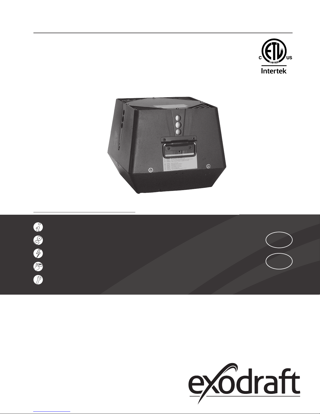
1. Product information
1.1 Function
Use exodraft Model GSV Grease Fan is designed to provide a large exhaust volume at a high discharge
velocity. It is intended for use as a part of a restaurant kitchen exhaust system and grease applications
according to NFPA 96. The use of the grease fan is not restricted to any type of chimney or grease
duct. However, always follow the exhaust-hood manufacturer’s instructions regarding the venting.
Construction The fan housing is made of heavy cast aluminum and can be opened for easy cleaning. The impeller is
of the backward inclined type. It is made of cast aluminum and has permanently attached balancing
weights.
The motor is a direct-drive, variable speed, class H insulated, high temperature motor. It has permanently lubricated and sealed ball bearings and is maintenance free.
Listings Installations must conform to the requirements of the authority having jurisdiction. Where required by the authority having jurisdiction, the installation must also conform to the NFPA 96. All electrical wiring must be in accordance with
the requirements of authority having jurisdiction or, in absence of such requirements, with the National Electrical Code,
NFPA 70.
GSV is tested and listed to UL Standard 705 for Power Ventilators and UL Standard 762 for Power Ventilators for restaurant
exhaust ventilators.
The model is also tested and listed to ULC-S645-93, Standard for Power Roof Ventilators for Commercial and Institutional
Kitchen Exhaust Systems.
3
1.2 Components
The GSV grease fan consists of the following components:
a. Top section f. Locking hinge
b. Bottom section g. Bird screen
c. Motor h. Carrying handle
d. Centrifugal impeller i. Wiring conduit
e. Inlet for impeller
Max. 575°F (300°C)
Fig. 1

4 • US
3001391_US_Grease_Fan_GSV200-450_171114
1.3 Shipping
Protection The fan is shipped in a corrugated cardboard box. If a transport securing device is attached (GSV 400
and GSV 450 only) to the bottom of the fan to hold the motor and impeller in place, do not remove
the transport securing device before the fan is ready for immediate installation.
Do not remove the transport securing device until the fan is being installed on the duct or the
roof curb. The motor shaft could be damaged.
NOTE
All single phase fans are shipped with a capacitor and junction box connected via conduit. The
capacitor is located INSIDE the junction box. Please do not discard.
1.4 Warranty
2-Year Factory Warranty
We promise the original user that we will replace or repair as we may elect, any part or parts of the new RS Chimney Fan
which are defective in material or workmanship without charge for parts and labor (not including labor for dismantling
and installation, freight, etc.) during the rst 2-years following the date of invoice.
10-Year Corrosion Perforation Warranty
We promise the original user that we will replace or repair as we may elect, any part or parts of the RS Chimney Fan which
are perforated due to corrosion without charge for parts or labor (not including dismantling and installation, freight, etc.)
during the rst 10-years following the date of invoice.
Complete warranty conditions are available at www.enervex.com or request a copy at:
info@enervex.com or at tel.: 1-800.255.2923.
 Loading...