

Page 1
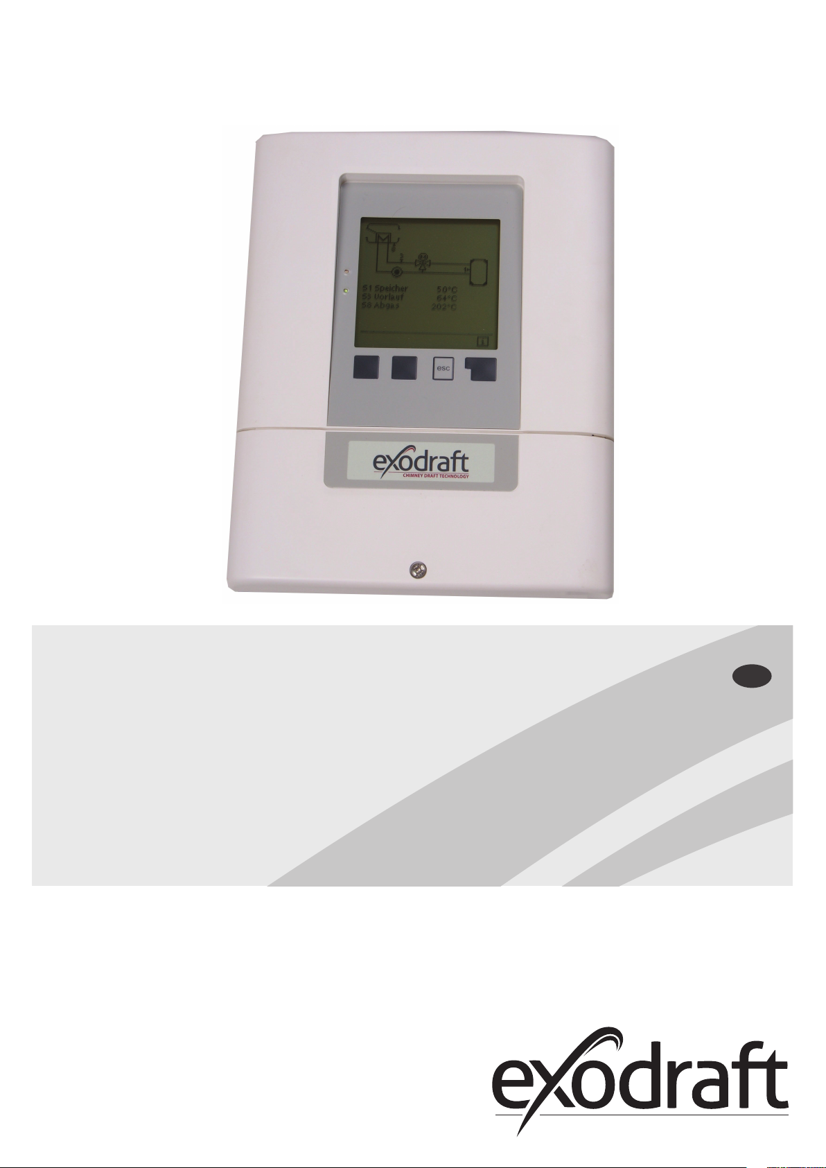
EHC20
Mounting, installation
and operating manual
Read and save these instructions!
GB
Page 2

2
3110086 EHC20 UK 110515
A. SUMMARY of assembly, installation and oper-
ating instructions. . . . . . . . . . . . . . . . . . . . . . 4
A.1 Description .......................... 4
A.2 About the automatic controller ....... 4
A.3 Scope of delivery..................... 4
B. Installation ........................ 5
B.1 Wall mounting ....................... 5
B.1.1 Housing base.......................5
B.1.2 Housing cover ......................5
B.2 Electrical connection ................. 6
B.3 Temperature sensor installation....... 6
C. Terminal plan and connections ..... 7
C.1 Terminal housing..................... 7
C.2 Terminal plan for electrical connection 7
D. Pin-out diagram ................... 8
D.1 Program 6.1.7 Heat exchanger with bypass
damper, one buer memory and mixer. .... 8
E. Installation note for 3-way mixing valve
10
E.1 SM230 with MV20/25/32 installation note
10
F. Service and start-up ..............11
F.1 Display and entry................... 11
F.2 Initial start-up with the start-up assistant
12
G. Lock menu .......................12
G.1 Activate/deactivate the lock menu .. 12
H. Option for heat quantity counter SE 20/SE 25/
SE 32 ................................13
H.1 Assembly and connection .......... 13
H.2 Start-up and set-up................. 14
I. SD card ..........................15
I.1 SD card ............................ 15
I.2 Logging............................ 15
I.3 Free storage........................ 15
I.4 Load conguration ................. 15
I.5 Save conguration ................. 15
I.6 Firmware update ................... 15
I.7 Ejection ............................ 15
J. Error messages ................... 16
J.1 Replacing a fuse .................... 16
J.2 Maintenance ....................... 17
K. Product information .............. 18
K.1 Description ........................ 18
K.2 About the controller................ 18
K.3 Items supplied ..................... 18
L. Controller description .............19
L.1 Technical data...................... 19
M. Installation ....................... 20
M.1 Wall mounting ..................... 20
M.1.1 Housing base......................20
M.1.2 Housing top .......................21
M.2 Electrical connection ............... 21
M.3 Installing the temperature sensors:.. 22
N. Terminal plan and connections .... 23
N.1 Terminal box ....................... 23
N.2 Terminal plan for electrical connections 23
N.3 Hydraulic variants / overview / systems 24
O. Connection diagrams .............26
O.1 Program 6.1.1. Heat exchanger without bypass
damper. With one storage tank. . . . . . . . . . . 26
O.2 Program 6.1.2. Heat exchanger without bypass
damper. With two storage tanks. ......... 28
O.3 Program 6.1.3 Heat exchanger without bypass
damper. With one storage tank and a mixer. 30
O.4 Program 6.1.4. Heat exchanger without bypass
damper. With two storage tanks and a mixer. 32
O.5 Program 6.1.5. Heat exchanger with bypass
damper. With one storage tank. . . . . . . . . . . 34
O.6 Program 6.1.6. Heat exchanger with bypass
damper. With two storage tanks. ......... 36
O.7 Program 6.1.7. Heat exchanger with bypass
damper. With one storage tank and a mixer. 38
O.8 Program 6.1.8. Heat exchanger with bypass
damper. With two storage tanks and a mixer. 40
O.9 Program 6.1.1. Heat exchanger with VFS sensor
for power measurement.................. 42
P. Operation ........................ 44
P.1 Display and entry system ........... 44
P.2 Setup wizard . . . . . . . . . . . . . . . . . . . . . . . 44
P.3 Unassisted setup ................... 45
P.4 Menu sequence and structure ...... 45
1. Measurements ...................46
2. Statistics .........................47
2.1 Operating hours.....................47
2.2 Heat quantity .......................47
2.3 Graphic overview....................47
2.4 Reports .............................47
2.5 Reset / delete .......................47
3. Operating mode .................. 47
3.1 Automatic...........................48
3.2 Manual..............................48
3.3 O ..................................48
4. Settings .......................... 48
4.1 Tmin S (X) ...........................48
4.2 Tmax S (X)...........................48
4.3 Priority S(X) .........................49
4.4 T priority ............................49
4.5 Filling time ..........................49
4.6 Temperature rise ....................49
5. Protective functions .............. 49
5.1 Anti-seize protection ................49
6. Special functions ................. 50
6.1 Program selection ...................50
6.2 Rotational speed control.............50
6.2.1 Rotational speed modes ...........50
6.2.2 Pump type ........................51
6.2.3 Pump settings .....................51
6.2.4 Purging time ......................53
6.2.5 Control time.......................53
6.2.6 Max. rotational speed ..............53
6.2.7 Min. rotational speed ..............53
6.2.8 Setpoint value .....................54
6.3 R2 rotational speed control ..........54
6.4 Relay functions ......................54
6.4.1 Thermostat........................54
6.4.2 Thermostat 2 ......................55
6.4.3 Cooling............................55
6.4.4 Return ow temperature rise.......56
6.4.5 Anti-Legionella function ...........56
6.4.6 Transfer ...........................57
6.4.7 Dierence .........................58
6.4.8 Solid fuel boiler....................59
6.4.9 Error messages ....................59
6.4.10 Pressure control ...................60
6.4.11 Booster pump .....................60
6.4.12 Parallel operation R (X) .............60
6.4.13 Parallel operation R2 ...............61
6.4.14 Permanently on ...................61
6.4.15 Heating circuit.....................61
6.5 Heat quantity .......................62
6.5.1 Forward ow sensor (X) ............62
6.5.2 Return ow sensor.................62
6.5.3 Glycol type ........................62
6.5.4 Proportion of glycol................62
6.5.5 Forward throughow (X)...........62
6.5.6 Oset ∆T ..........................62
6.5.7 VFS (X) ............................62
6.5.8 VFS position .......................63
6.5.9 Reference sensor ..................63
6.6 Pressure monitoring.................63
6.6.1 Pressure monitoring ...............63
6.7 Sensor calibration ...................63
6.8 Setup ...............................64
6.9 Factory settings .....................64
6.10 SD card .............................64
6.10.1 Logging ...........................
6.10.2 Free storage space.................64
6.10.3 Load conguration ................64
6.10.4 Save conguration.................64
6.10.5 Firmware update ..................64
6.10.6 Eject ..............................64
6.11 Time and date.......................65
6.12 Summer time .......................65
6.13 Power saving mode .................65
6.14 Ethernet ............................65
6.14.1 Ethernet...........................65
6.14.2 MAC address ......................65
6.14.3 TCP/IP address.....................65
6.14.4 Network mask . . . . . . . . . . . . . . . . . . . . .65
6.14.5 Gateway...........................65
6.14.6 Login..............................65
6.15 Temperature unit....................65
7. Menu lock ........................ 66
8. Service Data ...................... 66
9. Language ........................ 66
Q. Faults with error messages ........ 67
Q.1 Replace fuse ....................... 67
Q.2 Maintenance ....................... 68
R. Useful information / tips and tricks 69
64
Page 3
3110086 EHC20 UK 110515
Legend for symbols: The following symbols are used throughout the manual as warnings. They indicate potential
hazards or refer to important information relating to the product.
3
Prohibitory symbol:
Hazard symbol: Failure to observe information marked with a hazard symbol can result in injuries
Attention symbol: Information that is particularly important for the functioning and optimum use of
Failure to observe information marked with a prohibitory symbol can result in
serious injuries – or even death!
and/or damage to the device.
the device and the system.
TO REDUCE THE RISK OF FIRE, ELECTRIC SHOCKS OR PERSONAL INJURIES,
THE FOLLOWING RULES MUST BE OBSERVED:
• The device should only be used in the manner specied by the manufacturer. If you have any questions,
please contact the manufacturer. The address and telephone number of the manufacturer can be found
in the list at the end of this manual.
• Before maintaining or cleaning the device, switch it o at the service panel and lock the service panel so
that it cannot be turned on again accidentally.
• Installation work and work on the electrical connections should be carried out by specialists in
accordance with the laws and regulations in place.
• Observe the device manufacturer's guidelines and safety regulations as well as the ocial provisions in
force in the particular country.
• The device must be earthed.
No special requirements. The device must be disposed of in accordance with the ocial provisions
concerning the disposal of electronic waste.
Page 4

4 • Product information
3110086 EHC20 UK 110515
A. SUMMARY of assembly, installation and operating instructions
A.1 Description
The automatic controller was produced and tested while taking into account all requirements for high-quality and safety.
A two-year warranty from the date of sale applies to the device in accordance with the law.
However, the warranty and liability are not valid regarding damage to persons or property that, for example, are ascribed
to one or more of the following causes:
• Failure to follow these assembly instructions and service guide
• Incorrect assembly, start-up, maintenance or servicing
• Improper repairs carried out
• Unauthorised structural modications made to the device
• Installation of additional components that were not tested with the device
• Any damage resulting from continued use of the device in spite of an evident defect
• Failure to use original repair parts and accessories
• Failure to use the device as intended
• Exceedance of or failure to meet the limit values in the technical data
• Force majeure
A.2 About the automatic controller
The EHC temperature dierence controller enables you to eciently use and check the function of your heat exchanger.
Above all, the device gives you condence through its functionality and simple, almost self-explanatory, operation.
The individual entry keys are assigned to each dierent useful function and explained step-by-step. In the automatic
controller menu, help texts and clear graphics are also available in addition to keywords for measured values and
settings.
The EHC temperature dierence controller can be used with dierent systems.
A.3 Scope of delivery
• EHC20 temperature dierence controller
• Threescrews (3.5x35 mm) and threerawl-plugs (6mm) for wall mounting
• 12 strain relief clamps with 24 screws, replacement fuses 1x T2 A / 250 V
• Micro SD card + adapter
• EHC assembly and service guide
• Thermal compound
• One Pt1000 ue gas temperature sensor
• One Pt1000 pipe surface temperature sensor
• One Pt1000 Buer tank sensor with sleeve
Please use thermal compound with the temperature sensors to ensure better heat transfer.
Optionally included, depending on design/order:
• Flowsensor for energy measurement
Page 5

3110086 EHC20 UK 110515
161
11,8
195,4
9
R4.5
4.4
3333
139,3
n
3.5
169.3
B. Installation
B.1 Wall mounting
1. Loosen cover screw completely
2. Carefully remove the terminal cover from the bottom part. Loosen the two screws on the top part and
remove the top part from the base.
3. Mark the three mounting holes (see ”C.1.1 Housing base”). Make sure that the wall surface is as even as
possible so that the housing is not warped when attached.
4. Drill three holes in the wall at the marked places using a drill and #6 bit and insert the rawl-plugs.
5. Set the automatic controller on the upper screw.
6. Insert and screw in the two lower screws.
Only install the automatic controller in dry rooms and under the environmental conditions as
described in B.1 ”Technical Data”.
The automatic controller must not be accessible from the back!
Installation• 5
B.1.1 Housing base
B.1.2 Housing cover
Terminal housing cover
Cover screw
Page 6
6 • Installation
B.2 Electrical connection
Disconnect the power supply before working on the device and make sure that it cannot be
reconnected! Check that the power is o!
The electrical connection must only be carried out by qualied personnel in compliance with
the applicable laws. The automatic controller must not be put into operation if any damage is
visible on the housing, such as cracks.
Low-voltage cables such as temperature sensor cables must be routed separately from mains
voltage cables. Only put temperature sensor cables into the left side, and the mains voltage
cable into the right side of the device.
Safe isolation of the voltage supply to the automatic controller has been provided, such as
provision for an overheating emergency stop switch.
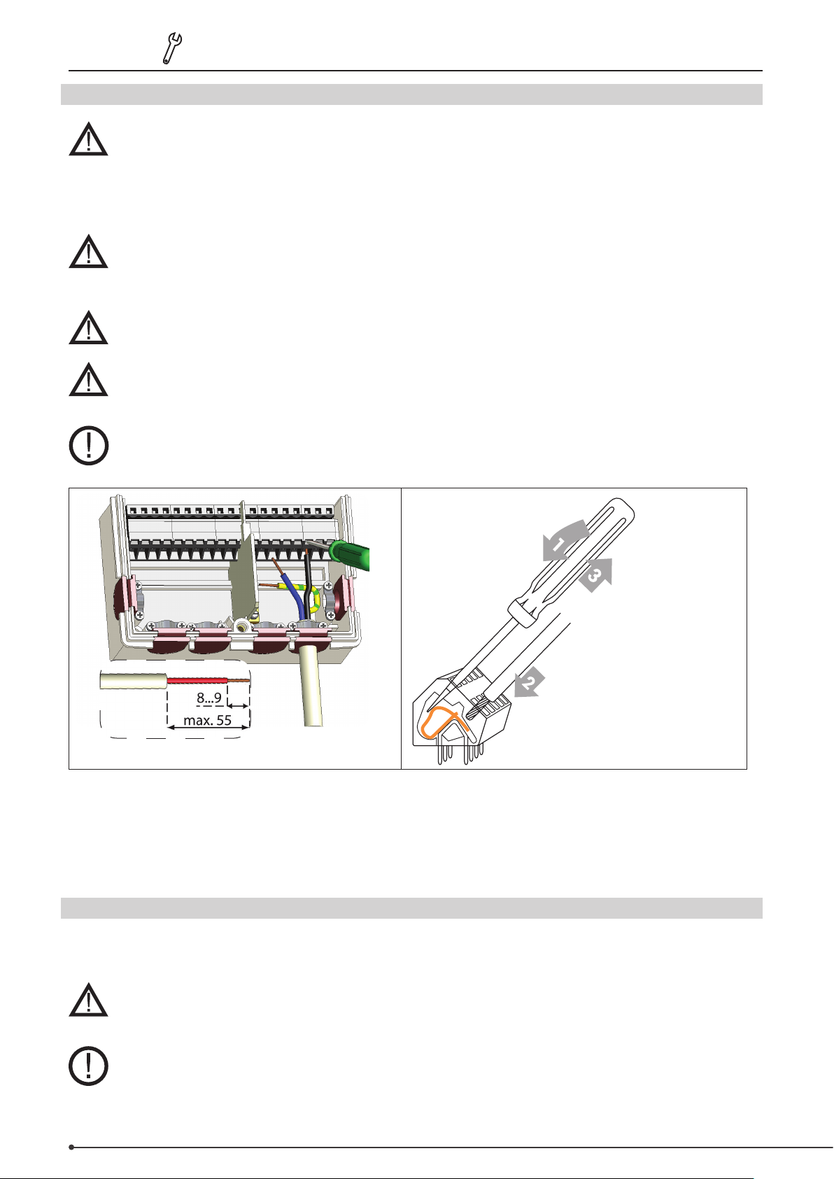
The cables to be connected to the device may be stripped up to maximum of 55mm and the
sheath should reach into the housing to exactly behind the strain relief.
The automatic controller and VFS sensor must have the same earthing potential. The VFS
sensor has a functional earthing (PELV). The peripheral unit terminal of the automatic
controller must be connected to the the piping system near the sensor.
3110086 EHC20 UK 110515
Terminal instructions
1. Insert a suitable screwdriver into the upper opening and press the lock handle down.
Leave the screwdriver in the opening.
2. Insert the cable into the lower opening.
3. Remove the screwdriver.
B.3 Temperature sensor installation
The automatic controller works with Pt1000 temperature sensors to ensure that the temperature is precisely recorded
so that the unit functions under technically optimal conditions.
The temperature sensor cables must be placed separately from the mains cables and must not,
for example, be placed in the same cables duct!
Place the sensors precisely in the area to be measured! Only use the feeder, tube or ush
sensor for the applicable area of use with the allowed temperature range that corresponds to
each. The thermal conductor must be used during assembly!
Page 7
3110086 EHC20 UK 110515
The sensor cables to S7/S8 may be extended to a maximum total length of 30 metres with a
cable that has a diameter of at least 0.75mm². The sensors from S1 to S6 may be extended to a
maximum total length of 10metres with a cable that has a diameter of at least 0.75mm².
Pay attention that no contact resistance occurs while joining the cables!
Connect the VFS direct sensors with the corresponding plug. In order to avoid damage to the
direct sensors, we strongly recommend only placing them in the return ow! Pay attention to
the correct ow direction when assembling the (VFS) direct sensors!
C. Terminal plan and connections
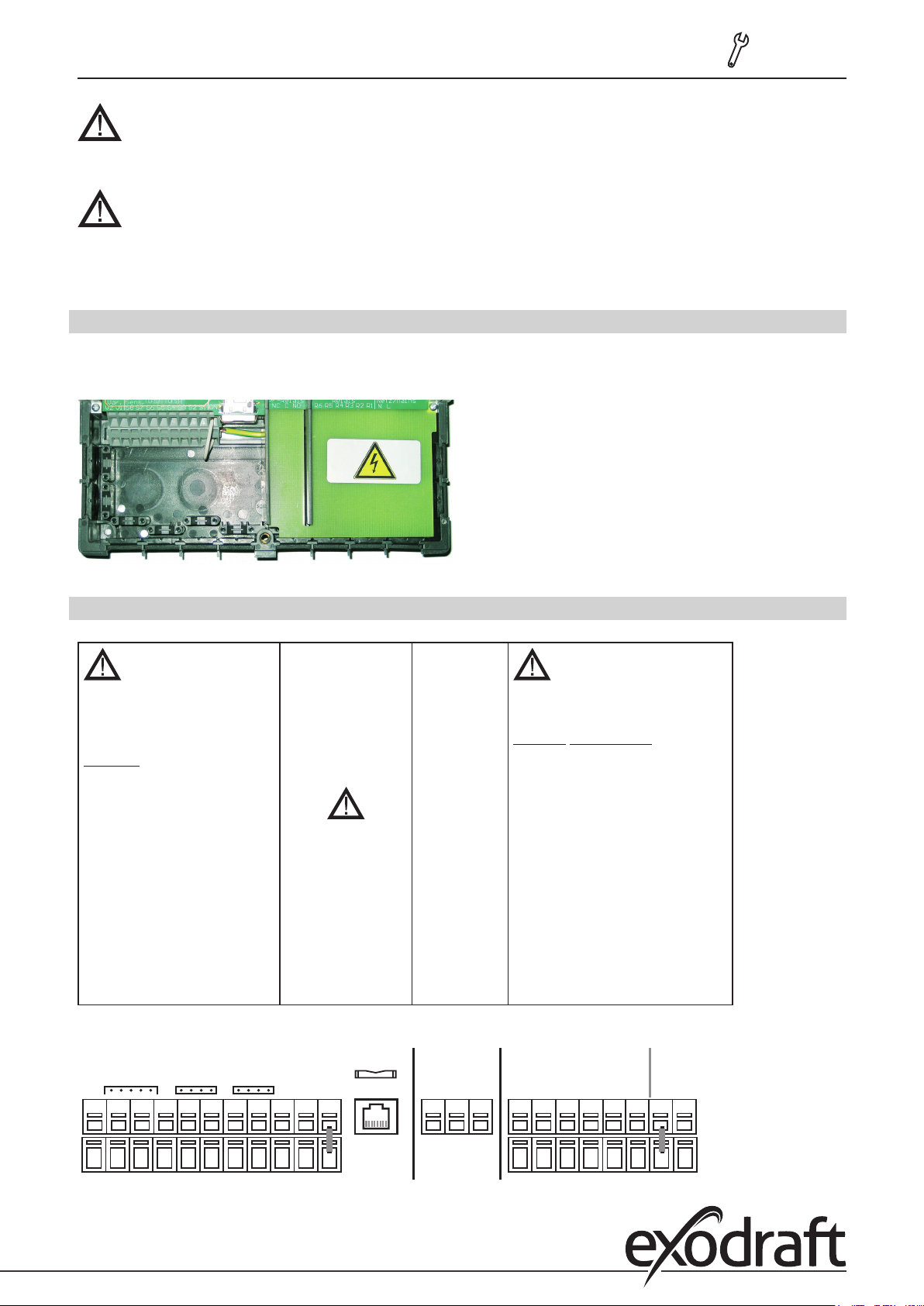
C.1 Terminal housing
The mains side of the terminal housing is protected on the right side by an additional plastic plate.
Before removing the plate, check that the power to the automatic controller has been switched o.
Installation• 7
C.2 Terminal plan for electrical connection
max. 12 V
Extra-low voltages
max. 12 VAC/DC
Terminals Connection for
S1 Sensor 1
S2 Sensor 2
S3 Sensor 3
S4 Sensor 4
S5 Sensor 5
S6 Sensor 6
S7 Sensor 7
S8 Sensor 8
V1 0-10 V/PWM
V2 0-10 V/PWM
VFS1 Grundfos Direct Sensor
VFS2 Grundfos Direct Sensor
RC Room controller
VFS2RC VFS1
SD card slot
for data storage and
updates
Ensure you insert
the card correctly!
The card must
enter without any
resistance, do not
force it into the
slot!
Ethernet (optional)
for linking to an LAN
SD Card
Potentially
free relay
NO
Normally
open
(closer)
C
Common
(Voltage)
NC
Normally
closed
(opener)
Mains
230 VAC
Mains voltages 230 VAC 50-60 Hz
Terminals Connection for
R1 Switch output 1 (speed)
R2 Switch output 2 (speed)
R3 Switch output 3
R4 Switch output 4
R5 Switch output 5
R6 Switch output 6
N Mains neutral cable N
L External mains line conduc
tor L
The peripheral unit protective earth
must be connected at the peripheral
unit of the metal terminal block!
Netz / MainsRelaisPF-RelaisKleinspannungen
-
V2 V1 S8 S7
S6 S5 S4 S3 S2 S1
GND
Ethernet
R6NC C NO R5 R4 R3 R2 R1 N L
Page 8

8 • Connection diagrams
R1
S1
R6
S8
R4
R5
VFS
S3
A1
V2 V1 S8 S7
VFS2RC VFS1
SD Card
Ethernet
S6 S5 S4 S3 S2 S1
GND
R6NC C NO R5 R4 R3 R2 R1 N L
S8 S3 S1 R4/R5 R1R6
ForsyningRelePF-ReleSvagtstrøm
3110086 EHC20 UK 110515
D. Pin-out diagram
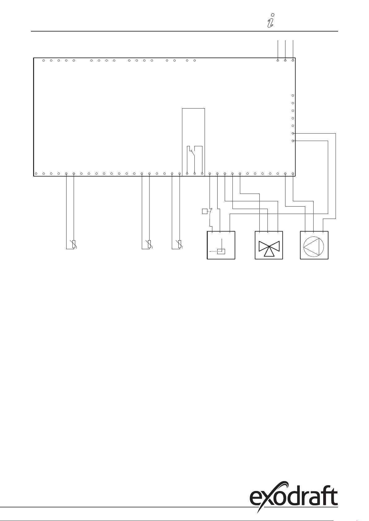
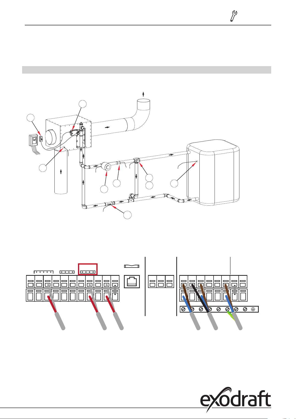
D.1 Program 6.1.7 Heat exchanger with bypass damper, one buer memory and mixer.
This diagram shows the following system:
Heat exchanger with bypass damper. A buer memory, a mixer and a circulating pump.
Place the S8 temperature sensor in the entry of the heat exchanger.
Mount the S3 temperature sensor on the supply pipe immediately behind the circulating pump.
Mount the S1 temperature sensor in the lower part of the buer memory.
VFS is the sensor for heat quantity measurement – optionally available.
A1 is the STB safety temperature limiter. Warning: only use with external sensors!
A2 Passage adjustment valve (provided).
The mixer should be mounted on R4 (brown/black) and R5 (black/brown). See SM230 with MV20/25/32 on page 9 of the
installation guide.
Mount the circulating pump on the R1 terminal.
Mount the bypass engine on the R6 terminal.
The lower terminal strip is the minus pole and/or the neutral point.
An STB safety temperature limiter must be mounted in the supply and must close the bypass damper at
a temperature of 100°C!
Page 9
3110086 EHC20 UK 110515
Connection diagrams • 9
N
L1
PE
1 111 12 2222 3 3 34 44 5
1 111 12 2222 3 3 34 44 5
CAN
RC stecker
VFS2 Sensor
VFS1 Sensor
CAN
exodraft EHC10/EHC20 Regler
PF-Relais
0-10V Ausgang
0-10V Ausgang
Temperaturfühlereingang 8
Temperaturfühlereingang 7
Temperaturfühlereingang 6
Temperaturfühlereingang 5
Temperaturfühlereingang 4
Temperaturfühlereingang 3
Temperaturfühlereingang 2
Temperaturfühlereingang 1
Relaisausgang 6
Relaisausgang 5
Relaisausgang 4
Relaisausgang 3
CGND GNDGND GNDGND GND GNDGNDGND GND
CGND GNDGND GNDGND GND GNDGNDGND GND
N NN
N NN
Schwartz/Braun
Blau
Braun/Schwartz
L
N
PE
L
N
PE
Netz / Mains
PE
PE
PE
PE
PE
PE
PE
PE
PE
PE
PE
PE
PE
PE
Relaisausgang 1
Relaisausgang 2
NNNNC NO
R1R2R3R4R5R6S1S2S3S4S5S6S7S8V1V2
NNNNC NO
R1R2R3R4R5R6S1S2S3S4S5S6S7S8V1V2
t°
STB Thermostat
N
N
L
L
PE
PE
CCWCW N CCWCW N
N
N
L
L
PE
PE
-S8
U
U
-S3
U
-S1
Rauchgastemperatur Vorlauftemperatur Pufferspeicher-
temperatur
MischerBypass Pumpe
Page 10
10 • Installation
3110086 EHC20 UK 110515
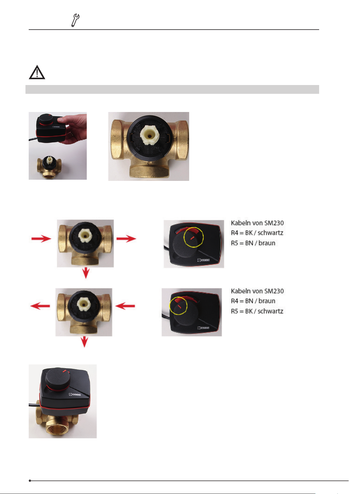
E. Installation note for 3-way mixing valve
Please pay attention to the installation note during use of the Exodraft SM230 with MV20 three-way mixing valve.
When using a dierent three-way mixing valve, please pay attention to the ow direction during
installation!
E.1 SM230 with MV20/25/32 installation note
Pay attention to the basic setting of the mixing valve and ow direction before installing the MV20/25/32!
The drive axle notch must be in the centre of the valve exit.
Please pay attention to the mixer setting in case of a change in ow direction:
Connect the motor to the valve and screw together. The motor is xed in place by removing the front cover.
Page 11
3110086 EHC20 UK 110515
F. Service and start-up
F.1 Display and entry
Operation • 11
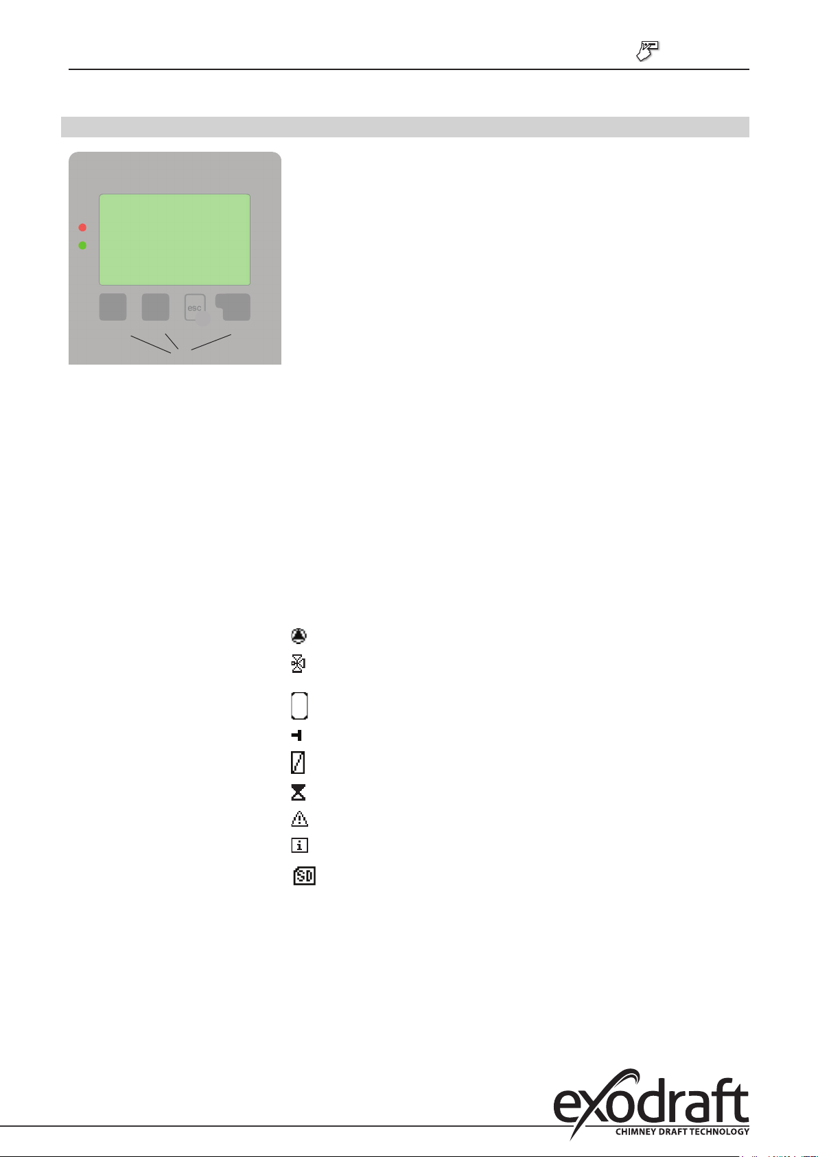
The display (1), which has extensive text and graphics modes, makes servicing
the automatic controller both simple and almost self-explanatory.
Please press the ESC key to return to the main menu.
(1)
(2)
(3)
(4)
Examples of key functions +/-
▼/▲
YES/NO
Information
Back
OK
Conrm
The green LED status light (2) illuminates when a relay is switched on, the red
LED light blinks in the event of an error message or when saving information.
Entries are made with 4 keys (3+4) that have various functions, depending on
the situation. The ESC key (3) is used to interrupt an entry or leave a menu.
If necessary, a security question will be displayed which asks if you wish to save
the completed changes.
The function of the other 3 keys (4) is explained in the display that is directly
above the keys; the key on the right is normally used to conrm and select.
Increase/Reduce values
Menu scroll up/down
Accept/Decline
Further information
about the previous display
Conrm selection
Conrm setting
Examples of display symbols
You can nd other symbols explained in the special functions menu.
Pump (swivels when in operation)
Valve (black indicates the direction of
ow)
Storage
Temperature sensor
Heat exchanger
Charging pause (see charging time)
Warning /Error message
New information available
Logging switched on
Page 12

12 • Operation
3110086 EHC20 UK 110515
F.2 Initial start-up with the start-up assistant
The start-up assistant will appear when you switch on the device for the rst time
and will guide you through the following menu:
1. Choose language –> press OK to conrm
2. Time and date –> adjust with the arrow keys and press OK to conrm each
selection. Press ESC to return to the previous menu.
3. Run start-up assistant –> press OK to conrm
The start-up assistant can also be terminated at any time and later restarted
from the special function menu.
4. Would you like to launch the start-up assistant? –> Press YES and follow the menu
5. Select 6.1.7 for mixer with bypass and one buer memory by using the arrow keys –> Press OK to conrm.
6. Follow the menu and set the following values, then press OK to conrm:
Designation/Description
6.20 Temperature unit
4.1 Tmin S8 – Heat exchanger
temperature sensors
4.4 ΔT S8, S1 - temperature
dierential
4.5 Tmax S1 –
Desired buer memory temperature
6.2.1 Rotation speed R1
Factory
settings
°C
60°C
10/3°C
60°C
From
Should be set
Yes: √/No: 0 /Conrm
Ø/Conrm
Ø/Conrm
Ø/Conrm x 2
Conrm/Use arrow
keys to change and
conrm
Ø /Conrm
Start-up values
90°C
7. To move to the next point, display CLOSE AND SAVE and conrm
8. Close and save –> Press YES to conrm
Congratulations! You have completed the start-up!
If the start-up assistant does not launch automatically, then it can be launched manually. Press ESC to
go to the main menu and select ”6. Special functions”. Select ”12. Start-up” on the menu and press OK.
After a successful start-up, the menu will automatically close
(deactivation: see chapter H)
G. Lock menu
The lock menu is used to prevent any unintentional changes to the entered values.
The following menu items remain fully accessible when the lock menu has been activated and can be adapted as
needed:
1. Measured values, 2. Evaluation, 6.23. Time & date, 8. Lock menu, 9. Service values
G.1 Activate/deactivate the lock menu
To activate/deactivate the lock menu, press ESC to return to the main menu and use the arrow keys to select menu
point ”7. Lock menu.”
It will indicate whether the lock menu is activated or not.
Press INFO to change the status of the lock menu.
1. Use the arrow keys to activate/deactivate the lock menu and press OK to conrm.
2. Leave the menu by pressing ESC.
3. ”Save changes?” –> press YES to conrm
You can press ESC now to leave the main menu.
Page 13
3110086 EHC20 UK 110515
Installation• 13
H. Option for heat quantity counter SE 20/SE 25/SE 32
The integrated VFS heat quantity counter and ow quantity meter (optional equipment) can be used to measure the
amount of recovered heat.
Warning! Not calibrated!
H.1 Assembly and connection
When installing the heat quantity counter (WPS), it is vital to pay attention to the ow direction, because otherwise
correct functioning cannot be ensured.
R6
A1
S8
R4
S3
R1
VFS
R5
Connect the EHC 20 by inserting the plug in the VFS1 connection socket.
Anschlussbuchse
V2 V1 S8 S7
Wärmemengezähler
VFS2RC VFS1
S6 S5 S4 S3 S2 S1
SD Card
GND
Ethernet
S1
R6NC C NO R5 R4 R3 R2 R1 N L
S8 S3 S1
R4/R5 R1R6
Page 14

14 • Operation
3110086 EHC20 UK 110515
H.2 Start-up and set-up
Select ”6. Special functions” in the main menu to start up the heat quantity counter, and then ”9. Heat quantity”.
Conrm each selection by pressing OK. Then follow the steps shown below:
1. ”1. Constant ow”
This will display whether the heat quantity counter is switched on or o.
To change this, press INFO and use the +/- key to select ON, then conrm.
2. ”2. Flow sensor”
This will display the threshold temperature for activating measurement of the ow temperature.
Press INFO to open the menu and use the +/- key to select ”S3 ow” and conrm.
3. ”4. Return ow sensor”:
This will show which temperature sensor is activated for measurement of the return ow temperature.
Press INFO to open the menu and use the +/- key to select ”VFS 1T” and conrm.
4. ”5. Glycol type”
If you use glycol in your system, enter the exact type of liquid used here.
If you do not use antifreeze, then enter the following:
Press INFO to open the menu and conrm ”propylene”.
5. ”6. Glycol percentage”
Press INFO to open the menu and use the +/- keys to set the value to ”0%”.
6. ”7. Supply ow”
Press INFO to open the menu and select the nominal ow rate for the VFS quantity counter. Conrm
7. ”9. ΔT oset
Press INFO to open the menu and set the correction factor for the temperature dierence as needed.
Otherwise, set and conrm ”0%”
8. Press ESC to leave the menu
9. ”Save changes?” –> Press YES to conrm
Page 15
3110086 EHC20 UK 110515
Product information • 15
I. SD card
You can store the current conguration, measurement results, etc. on the included SD card or overwrite a software
update on the automatic controller.
To do this, press ESC to go to the main menu and select ”6. Special functions” and then select menu item ”14. SD card”
I.1 SD card
Setting the logging function with data storage on the SD card
I.2 Logging
In this menu, the sensor and relay data recording is activated or deactivated.
The display shows whether logging is activated or deactivated.
To change this, press INFO and use the +/- key to select ”ON” or ”OFF” and conrm.
It must be set to ”ON” to activate the sensor and relay data recording.
I.3 Free storage
This displays the available storage space on the SD card.
I.4 Load conguration
This function allows you to load all the automatic controller settings on the SD card.
All previous settings in the automatic controller will be overwritten.
I.5 Save conguration
This function allows you to save all the settings in the automatic controller, including the service values, onto the SD
card.
To do this, press the ESC key to go to the main menu.
I.6 Firmware update
This function copies rmware that has been saved on the SD card to the automatic controller.
Never switch o or disconnect the automatic controller during a rmware update – this can
cause irreparable damage.
Settings may be changed and/or overwritten. Reset the automatic controller back to the
factory settings after any rmware update and perform a new start-up.
I.7 Ejection
To prevent any damage or loss of data, you must safely log-out before ejecting the SD card.
Page 16
16 • Faults with error messages
J. Error messages
(LED ashes + warning
symbol)
3110086 EHC20 UK 110515
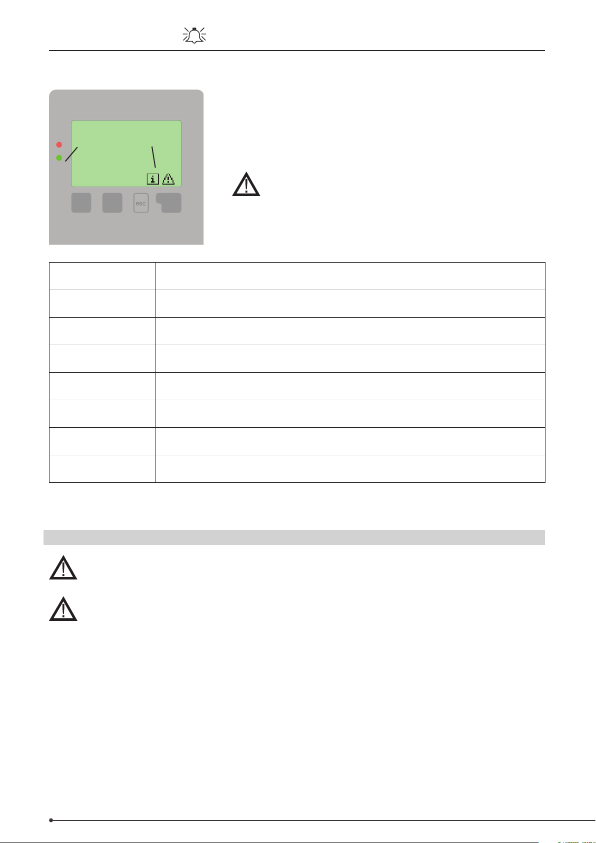
If the automatic controller recognises a malfunction, the warning symbol
will appear in the display. When the error is corrected, then the warning
symbol changes to an information symbol.
Further information about the error may be obtained by pressing the key
under the warning or information symbol.
Do not act on your own accord.
Ask a specialist for advice in the event of problems!
Possible error
messages
Sensor error Either the sensor, sensor entry on the automatic controller or the connection cable is/was
Restart Means that the automatic controller was restarted, e.g., because of a loss of power.
Time and date This display appears automatically after a lengthy loss of power because the time and date
Strong clocking This is displayed if the pump switches on and o more than 5 times in 5 minutes (that is, in
No ow Displayed if the steam turbine is >=50°C for more than 5minutes while the pump is on.
Excessive/Insucient
system pressure
SD card error Displayed when an SD card is recognised but the automatic controller cannot read it or
Notes for the specialist
defective.
Check the date and time!
must be checked and, if necessary, reset.
the event of 11 starts and stops).
Displayed if Pmin and/or Pmax is less or more than allowed when the pressure monitor is
switched on.
write to it.
J.1 Replacing a fuse
Repair and maintenance may only be carried out by a specialist. Disconnect the power supply
before working on the device and secure against reconnection! Make sure the power is o!
Only use the spare fuse included, or a fuse that is constructed in an identical manner and has
the following characteristics: T2 A / 250 V.
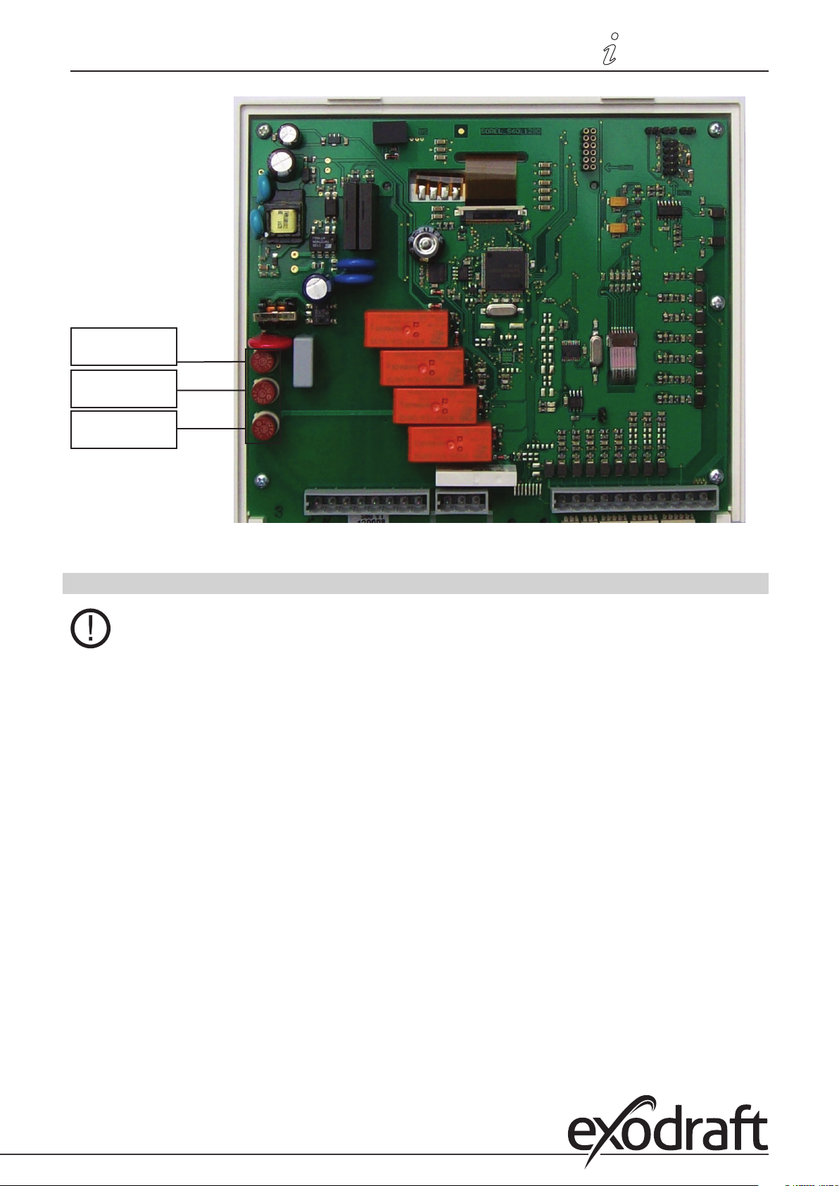
Three fuses have been installed in the automatic controller that protect the dierent relays as well as the controller
electronics. If the automatic controller has no function or display when it is connected to power, or no mechanical or
electronic relays are functioning, then open the device as described under C, below, then remove and check all fuses.
Change the defective fuse, and nd and exchange any external defective parts (e.g. pump).
Finally, restart the automatic controller.
Page 17
3110086 EHC20 UK 110515
Fuses
T2 A/250 V
Circuit board
Electronic relays
Mechanical relays
Product information • 17
J.2 Maintenance
In the course of the annual general servicing of your heater, you should also have the specialist
check the functions of the automatic controller and, if necessary, optimise its settings.
Carrying out maintenance
• Checking the date and time
• Assessment/Plausibility check of the evaluations
• Managing the error log memory
• Check/Plausibility check of the current measured values
• Managing the switch outputs/loads in manual operation
• Possible optimisation of the set parameters
Page 18

18 • Product information
3110086 EHC20 UK 110515
K. Product information
K.1 Description
The controller was produced and tested in accordance with strict quality and safety requirements. The legal warranty
period of two years from the date of sale applies to the device.
However, the manufacturer shall accept no liability or warranty claims for personal injuries and damage to property
resulting from one or more of the following:
• Failure to observe these mounting and operating instructions
• Incorrect mounting, setup, maintenance and operation
• Improper repairs
• Unauthorized modications to the device
• Installation of additional components that were not tested together with the device
• All damages resulting from continued use of the device in spite of an obvious defect
• Failure to use original spare parts and accessories
• Use of the device in an unintended manner
• Failure to observe the limit values set out in the technical data
• Force majeure
K.2 About the controller
The EHC temperature dierential controller helps you to use your heating system and control its functions eciently.
The device has an impressive range of functions and is virtually self-explanatory in use. The individual entry buttons
have specic functions and are explained in the context of each step. In the controller menu, you will nd not only
keywords but also help texts and clear graphics relating to the measurements and settings.
The EHC can be used as a temperature dierential controller for various types of systems . These are illustrated and
explained from page 24 onwards.
Key features of the EHC:
• Illuminated display showing graphics and texts
• Straightforward querying of current measurements
• Various options for evaluating and monitoring the system, e.g. graphical statistics
• Extensive settings menus with explanations
• Menu lock function to prevent accidental changes
• Reset option for restoring previous values or factory settings
• Various additional functions are optionally available
K.3 Items supplied
• EHC temperature dierential controller
• 3 screws (3.5 x 35 mm) and 3 plugs (6 mm) for wall mounting
• 12 strain relief clamps with 24 screws, replacement fuses 1x T2 A / 250 V
• Micro SD card
• EHC mounting and operating manual
Optionally supplied depending on model/order:
• Pt1000 temperature sensors and thermowells
• Ethernet connection
Also available:
• Pt1000 temperature sensors, thermowells, overvoltage protection
• CAN bus data logger
Page 19

3110086 EHC20 UK 110515
L. Controller description
L.1 Technical data
Electrical data:
Mains voltage 100 - 240 VAC
Mains frequency 50 - 60 Hz
Power consumption 0.5 - 3 W
Switching power
Total electronic relay switching power: 460 VA for AC1 / 240 W for AC3
Electronic relay R1 Min. 5 W...max. 120 W for AC3
Electronic relay R2 Min. 5 W...max. 120 W for AC3
Total mechanical relay switching power: 460 VA for AC1 / 460 W for AC3
Mechanical relay R3 460 VA for AC1 / 460 W for AC3
Mechanical relay R4 460 VA for AC1 / 460 W for AC3
Mechanical relay R5 460 VA for AC1 / 460 W for AC3
Mechanical relay R6 460 VA for AC1 / 460 W for AC3
Potential-free relay R7 460 VA for AC1 / 185 W for AC3
0..10V output Designed for 10 kΩ load resistance
PWM output Freq. 1 kHz, level 10 V
Internal fuse 2A slow-blow 250 V (3x)
Protection type IP40
Protection class II
Overvoltage category II
Pollution level II
Sensor inputs 8 x Pt1000
2 x Grundfos direct sensors
1 x RC21
Measuring range
PT1000 -40°C to 300°C
Grundfos direct sensor: 0°C - 100°C (-25°C / 120°C briey)
Controller description • 19
VFS 1 l/min - 12 l/min (VFS1-12) RPS 0 - 0.6 bar
2 l/min - 40 l/min (VFS2-40) 0 - 1 bar
5 l/min - 100 l/min (VFS5-100) 0 - 1.6 bar
10 l/min - 200 l/min (VFS10-200) 0 - 2.5 bar
0 - 4 bar
0 - 6 bar
0 - 10 bar
Permitted total cable lengths:
Sensors S7 and S8 <30 m
Other Pt1000 sensors <10 m
VFS/RPS sensors <3 m
CAN <3 m
PWM/ 0...10 V <3 m
Electronic relay <3 m
Mechanical relay <10 m
Network connections
Ethernet (optional)
CAN bus
Storage medium Micro SD card slot
Real time clock RTC with 24-hour power backup
Permitted ambient conditions:
Ambient temperature
during controller operation 0°C...40°C
during transport/storage 0°C...60°C
Air humidity
during controller operation Max. 85% rel. humidity at 25°C
during transport/storage No condensation allowed
Other data and dimensions
Housing design Three-part, ABS plastic
Installation options Wall mounting, switch panel mounting (optional)
Overall dimensions 228 x 180 x 53 mm
Display Fully graphical display, 128 x 128 dots
LEDs 2:, 1 x red, 1 x green
Operation 4 entry buttons
Page 20
20 • Installation
161
11,8
195,4
9
R4.5
4.4
3333
139,3
n
3.5
169.3
M. Installation
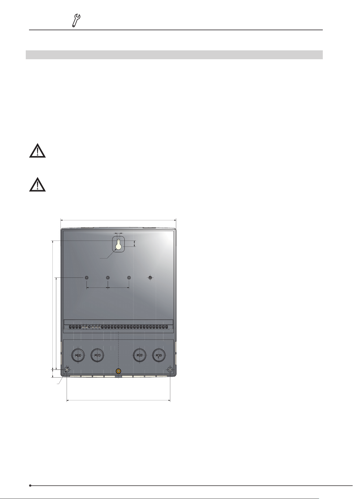
M.1 Wall mounting
1. Completely loosen the cover screw
2. Carefully remove the terminal box cover from the bottom section. Loosen the two screws in the top
section and remove the top section from the base.
3. Mark the three xing holes (see ”C.1.1 Housing base”). Make sure that the wall surface is as at as
possible to prevent the housing distorting when the screws are tightened.
4. Using a drill and a size 6 mm bit, drill three holes in the wall at the points marked and insert the plugs.
5. Mount the controller from the top screw.
6. Insert the two bottom screws and tighten them.
Install the controller only in rooms that are dry and meet the environmental requirements set
out in “B.1 Technical data”.
The controller must not be accessible from behind.
3110086 EHC20 UK 110515
M.1.1 Housing base
Page 21

3110086 EHC20 UK 110515
M.1.2 Housing top
Terminal box cover
Cover screw
M.2 Electrical connection
Before working on the device, disconnect the power supply and ensure that the device cannot
be switched on again! Check that the power is switched o.
The electrical connection work should only be carried out by a specialist in accordance with the
regulations in place. The controller must not be used if there is visible damage to the housing,
e.g. cracks.
Installation• 21
Extra low voltage leads such as temperature sensor leads should be kept away from the mains
cables. Temperature sensor leads should only be inserted into the left-hand side and mains
cables only into the right-hand side of the device.
An omnipolar cut-o device, e.g. an emergency heating switch, should be tted to the power
supply system for the controller by the customer.
No more than 55 mm of the sheath on the leads that are to be connected to the device should
be stripped, and the sheath should reach just beyond the strain relief clamp where the cable
enters the housing.
The controller and VFS sensor must have the same ground potential. The VFS sensor has a
functional earthing system (PELV). The controller’s PE terminal must be connected to the pipe
system close to the sensor.
Page 22
22 • Installation
M.2.1
M.2.2
3110086 EHC20 UK 110515
1. Select the required program/hydraulic system (see
"N.3 Hydraulic variants / overview / systems", page
24)
2.
Open the terminal box cover ("N.1 Terminal box", page
23)
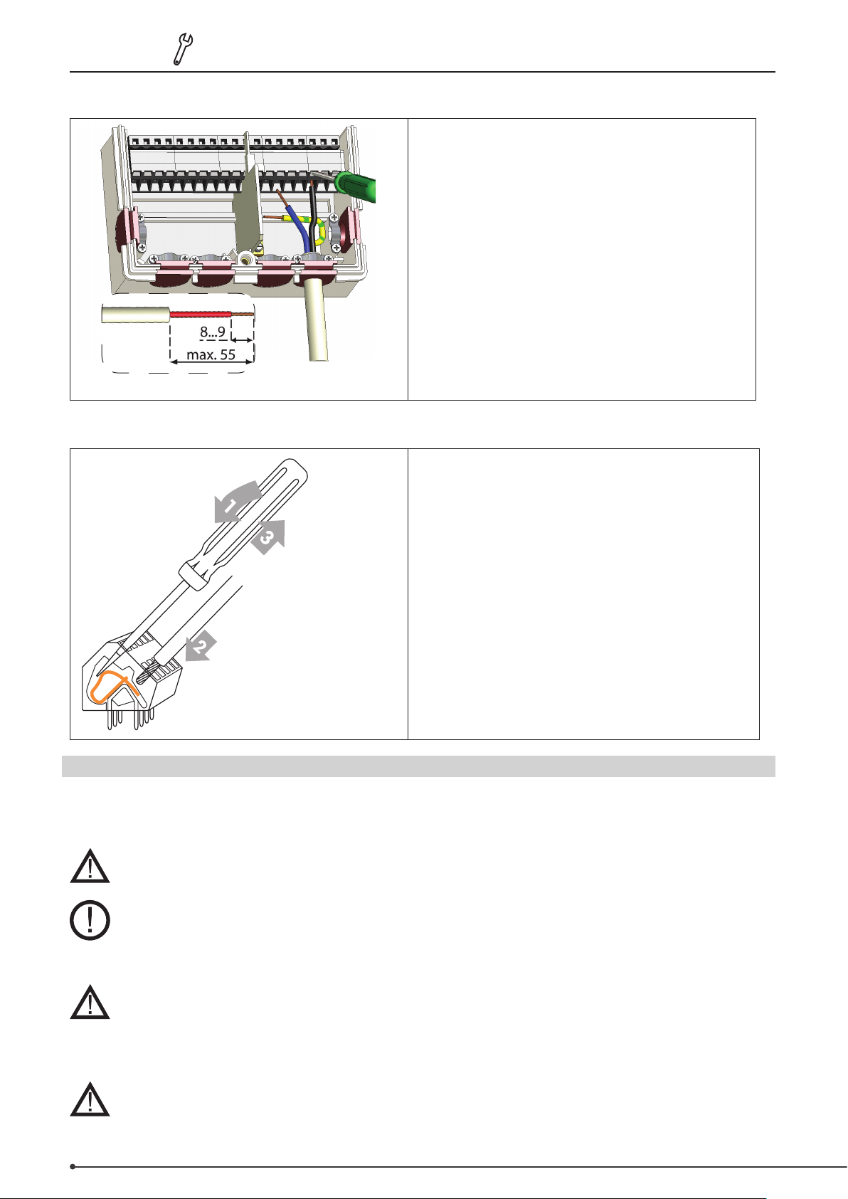
3. Strip no more than 55 mm of the cable sheath, insert
cables, attach the strain relief clamps, strip 8-9 mm of
the insulation o the ends of the wires (Fig. ”M.2.1”)
4. Open the terminals using a suitable screwdriver
(Fig. ”M.2.2”) and connect the power supply to
thecontroller
5. Replace the terminal box cover and secure it with
thescrew
6. Switch on the mains power and begin using the
controller
Instructions for terminals:
1. Insert a suitable screwdriver into the top opening
and push the locking bar downwards. Keep the
screwdriver in this position.
2. Insert the cable into the bottom opening.
3. Remove the screwdriver.
M.3 Installing the temperature sensors:
The controller works with Pt1000 temperature sensors. These measure the temperature extremely accurately and thus
ensure that the system functions optimally from a control point of view.
The temperature sensor leads should be kept separate from the mains power cables and must
for example not be routed through the same cable channel.
Position the sensors exactly in the area to be measured! Use only the immersion pipe or atmounted sensor with the appropriate permitted temperature range for the particular
application.
If necessary, the sensor lead connected to S7/S8 can be extended to a maximum length of 30 m
using a cable at least 0.75 mm² in size. The sensor leads connected to S1 to S6 can be extended
to a maximum length of 10 m using a cable at least 0.75 mm² in size.
When connecting the cables, ensure that no transition resistances occur.
The VFS direct sensors should be connected using the appropriate plugs.
To avoid damaging the direct sensors, it is recommended that you position them only in the
return ow.
When mounting the direct sensor (VFS), the correct ow direction must be observed.
Page 23
3110086 EHC20 UK 110515
V2 V1 S8 S7
VFS2RC VFS1
SD Card
Ethernet
S6 S5 S4 S3 S2 S1
GND
R6NC C NO R5 R4 R3 R2 R1 N L
MainsRelaysPF relaysExtra low voltages
Connection diagrams • 23
N. Terminal plan and connections
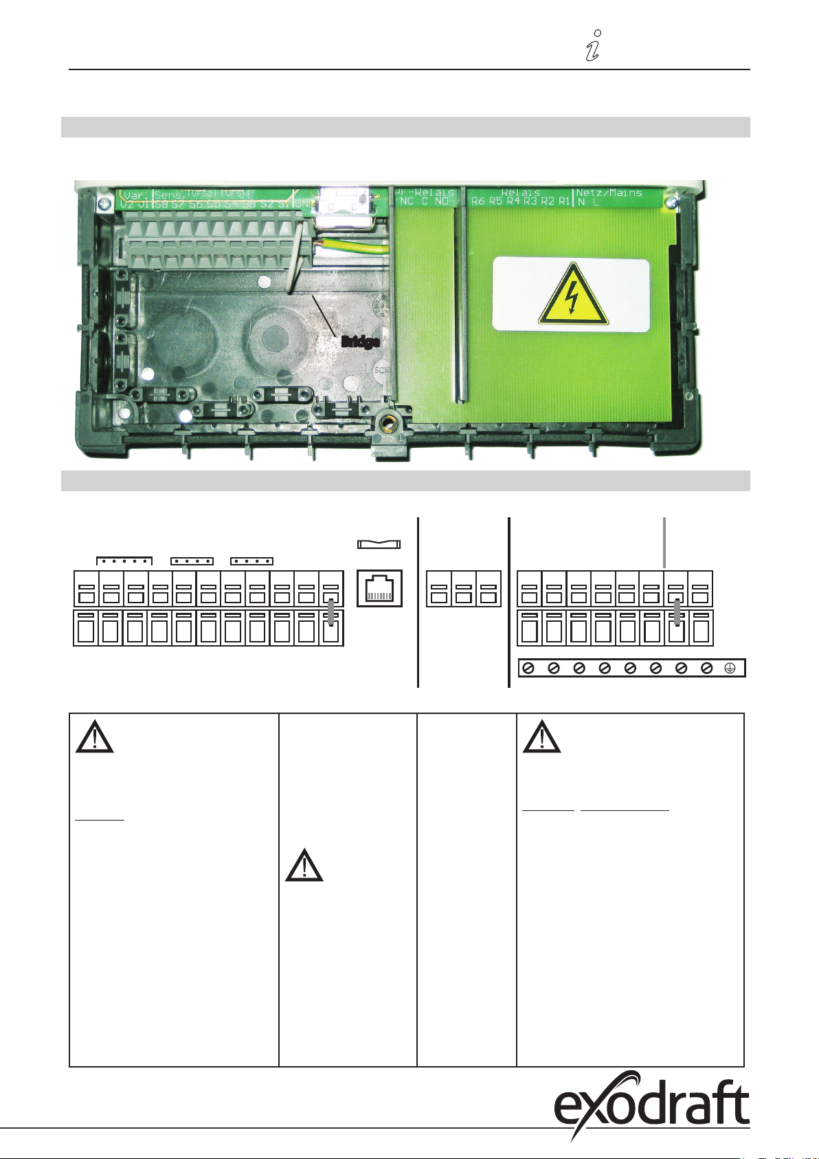
N.1 Terminal box
The mains section on the right-hand side of the terminal box is protected by an additional plastic panel.
Before removing this, ensure that the controller has been disconnected from the power supply.
Bridge
N.2 Terminal plan for electrical connections
Extra low voltages
Max. 12 VAC/DC
Terminal: Connection for:
S1 Sensor 1
S2 Sensor 2
S3 Sensor 3
S4 Sensor 4
S5 Sensor 5
S6 Sensor 6
S7 Sensor 7
S8 Sensor 8
V1 0-10 V / PWM
V2 0-10 V / PWM
VFS1 Grundfos direct sensor
VFS2 Grundfos direct sensor
RC Room controller
Max. 12 V
SD card slot
for data storage and
updates
Ensure that the card is
the right way around!
The card should lock
with no resistance,
do not use excessive
force!
Ethernet (optional)
For connecting to a
LAN
Potential-free
Mains voltages 230 VAC 50-60 Hz
relay
Terminal: Connection for:
NO
Normally open
(closer)
R1 Switch output 1 (rot. sp.)
R2 Switch output 2 (rot. sp.)
R3 Switch output 3
R4 Switch output 4
C
Common
R5 Switch output 5
R6 Switch output 6
(voltage)
N Mains neutral wire N
NC
L Mains live wire L
Normally closed
(opener)
The PE earth wire should be connected
to the PE metal terminal block!
Mains
230 VAC
Page 24
24 • Connection diagrams
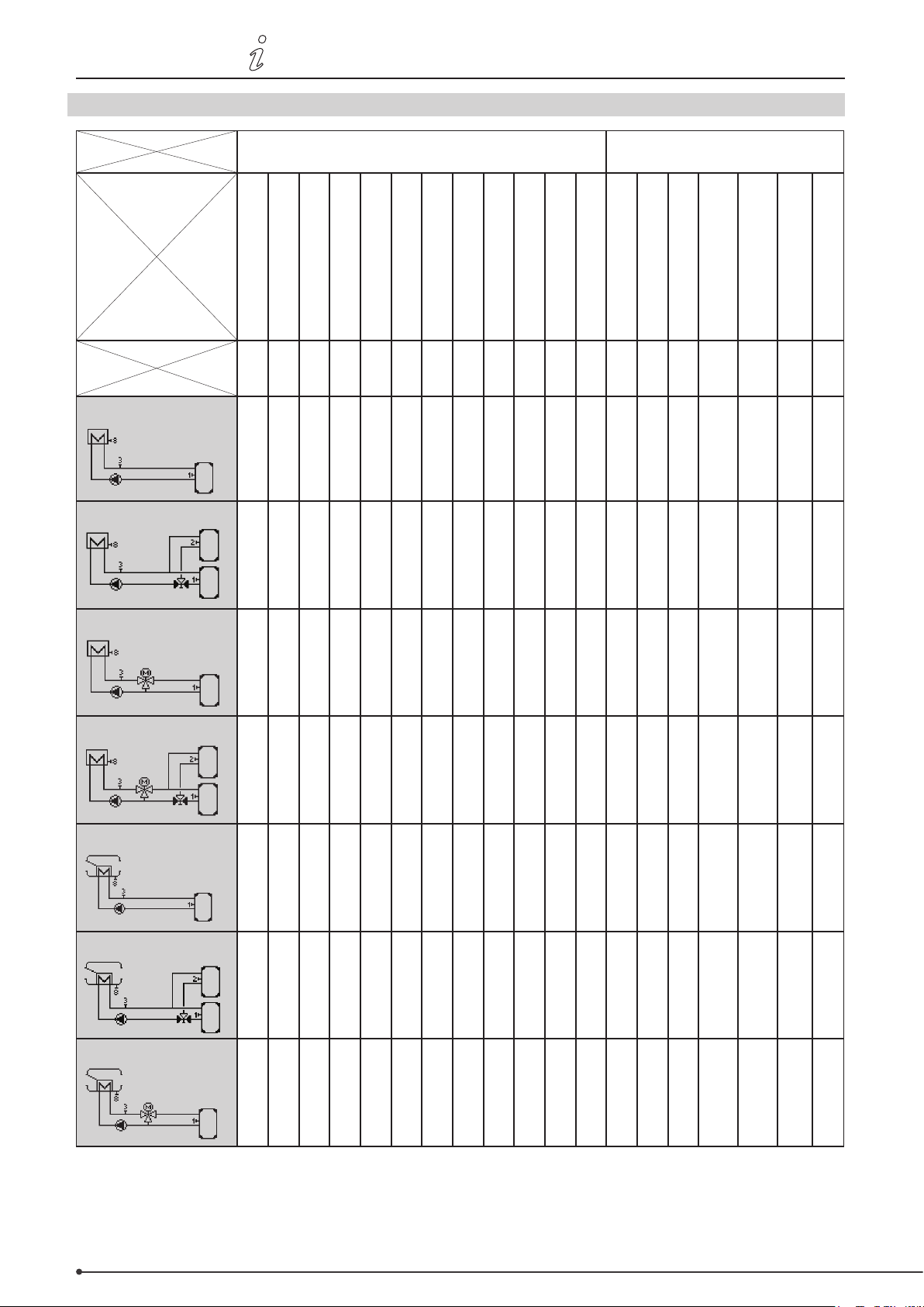
N.3 Hydraulic variants / overview / systems
3110086 EHC20 UK 110515
Program 6.1.1
Program 6.1.2
Temperature sensors
Storage tank temp. 1
Storage tank temp. 2
S1 S2 S3 S4 S5 S6 S7 S8 VFS1 VFS2 V1 V2
X X X X X
X X X X X X X
Extra low voltage only
Forward ow temperature
Flue temperature
0-10 V signal pump
Circulator pump
R1
(ELR)R2(ELR)
Relay connections
230 VAC
Three-way valve
High temperature mixer
valve
R3 R4 R5 R6R7(pot.-
Low temperature mixer
valve
Bypass damper
free)
Program 6.1.3
Program 6.1.4
Program 6.1.5
Program 6.1.6
Program 6.1.7
X X X X X X
X X X X X X X X
X X X X X X
X X X X X X X X
X X X X X X X X
Page 25
3110086 EHC20 UK 110515
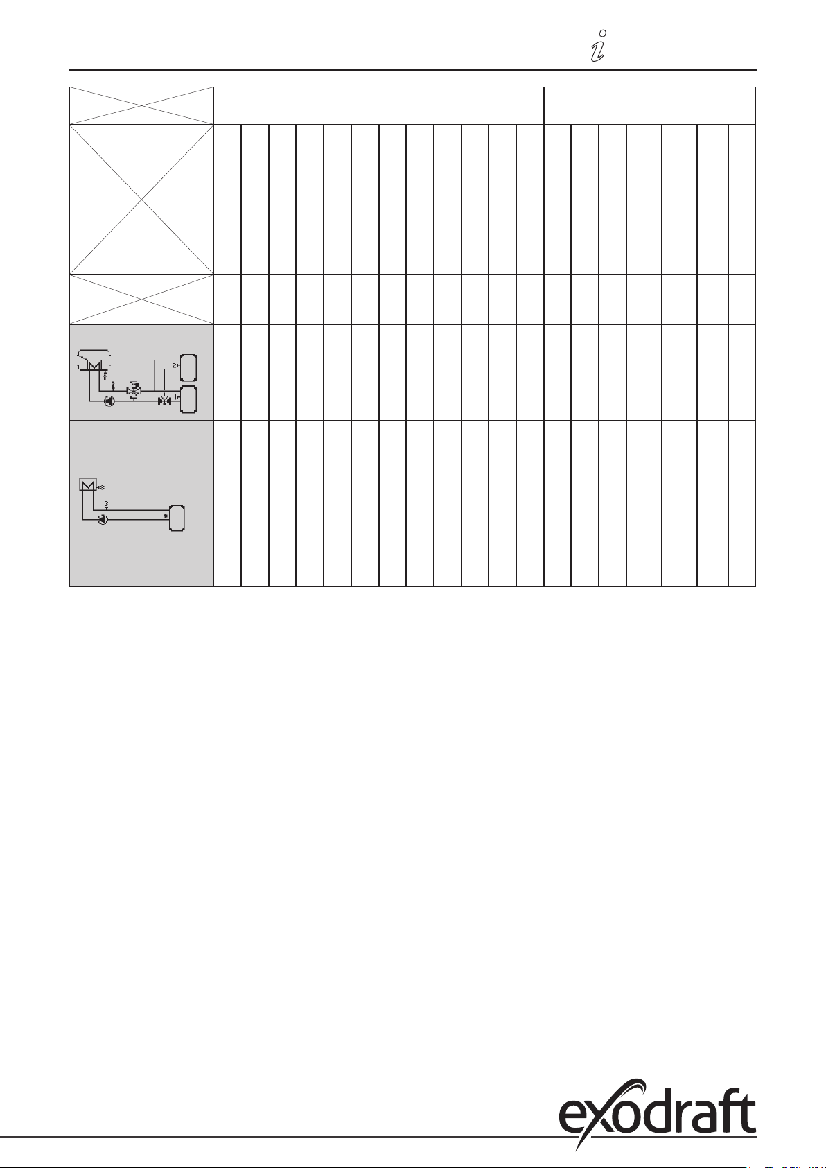
Connection diagrams • 25
Program 6.1.8
Program 6.1.1 with
VFS-Sensor
Temperature sensors
Storage tank temp. 1
Storage tank temp. 2
S1 S2 S3 S4 S5 S6 S7 S8 VFS1 VFS2 V1 V2
Extra low voltage only
Forward ow temperature
Flue temperature
0-10 V signal pump
Circulator pump
R1
(ELR)R2(ELR)
Relay connections
230 VAC
Three-way valve
High temperature mixer
valve
R3 R4 R5 R6R7(pot.-
Low temperature mixer
valve
X X X X X X X X X
Bypass damper
free)
(VFS-Sensor can be
used with all systems )
X X X X X X
Page 26
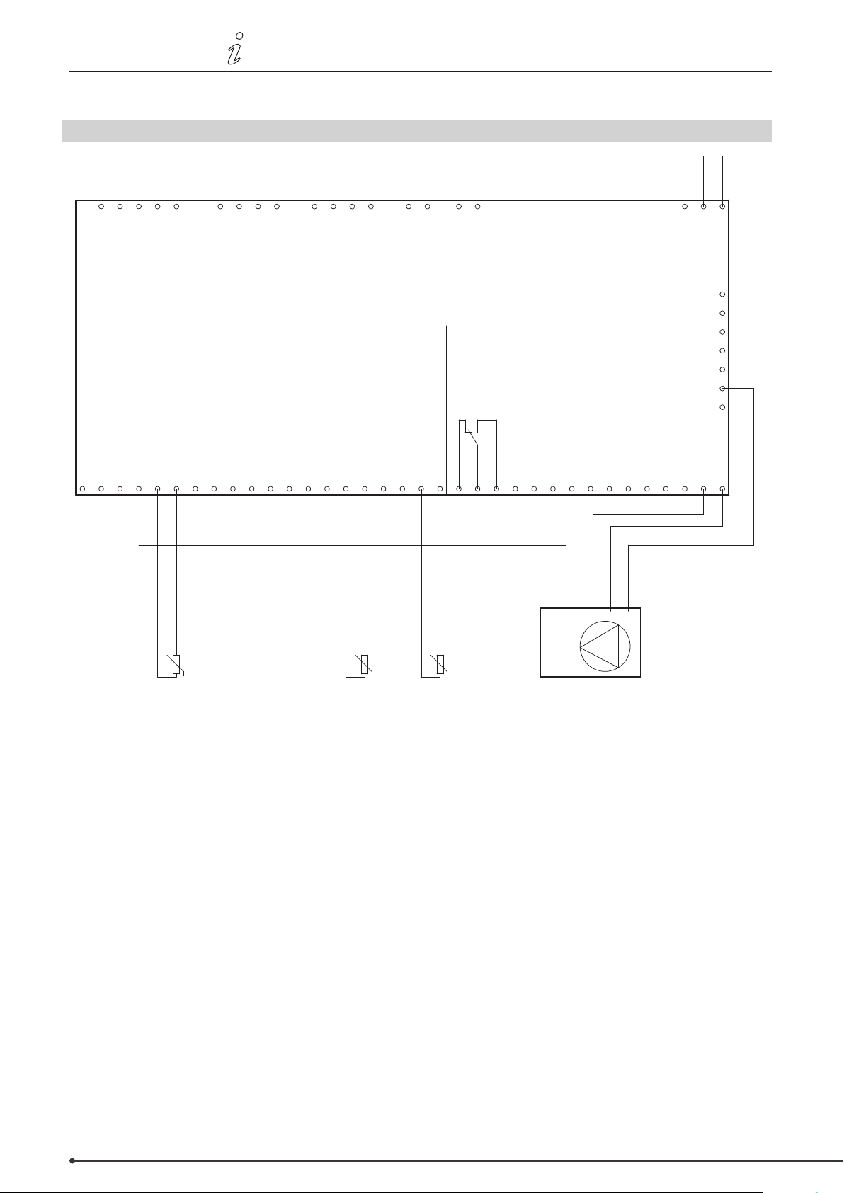
26 • Connection diagrams
3110086 EHC20 UK 110515
O. Connection diagrams
O.1 Program 6.1.1. Heat exchanger without bypass damper. With one storage tank.
N
L1
PE
0-10V output
RC plugs
0-10V output
1 111 12 2222 3 3 34 44 5
1 111 12 2222 3 3 34 44 5
VFS2 sensors
CAN
VFS1 sensors
CAN
exodraft EHC10/EHC20 controller
PF relay
Temperature sensor input 8
Temperature sensor input 7
Temperature sensor input 6
Temperature sensor input 5
Temperature sensor input 4
Temperature sensor input 3
Temperature sensor input 2
Temperature sensor input 1
Relay output 6
Relay output 5
Relay output 4
Relay output 3
CGND GNDGND GNDGND GND GNDGNDGND GND
CGND GNDGND GNDGND GND GNDGNDGND GND
N NN
N NN
GND/0V
GND/0V
L N
L N
PE
0-10V
0-10V
PE
L
N
PE
L
N
PE
Mains
PE
PE
PE
PE
PE
PE
PE
PE
PE
PE
PE
PE
PE
PE
Relay output 1
Relay output 2
NNNNC NO
R1R2R3R4R5R6S1S2S3S4S5S6S7S 8V1V2
NNNNC NO
R1R2R3R4R5R6S1S2S3S4S5S6S7S 8V1V2
U
-S8
Smoke gas temperature Forward flow
-S3
temperature
U
Storage tank temperature
-S1
U
Pump
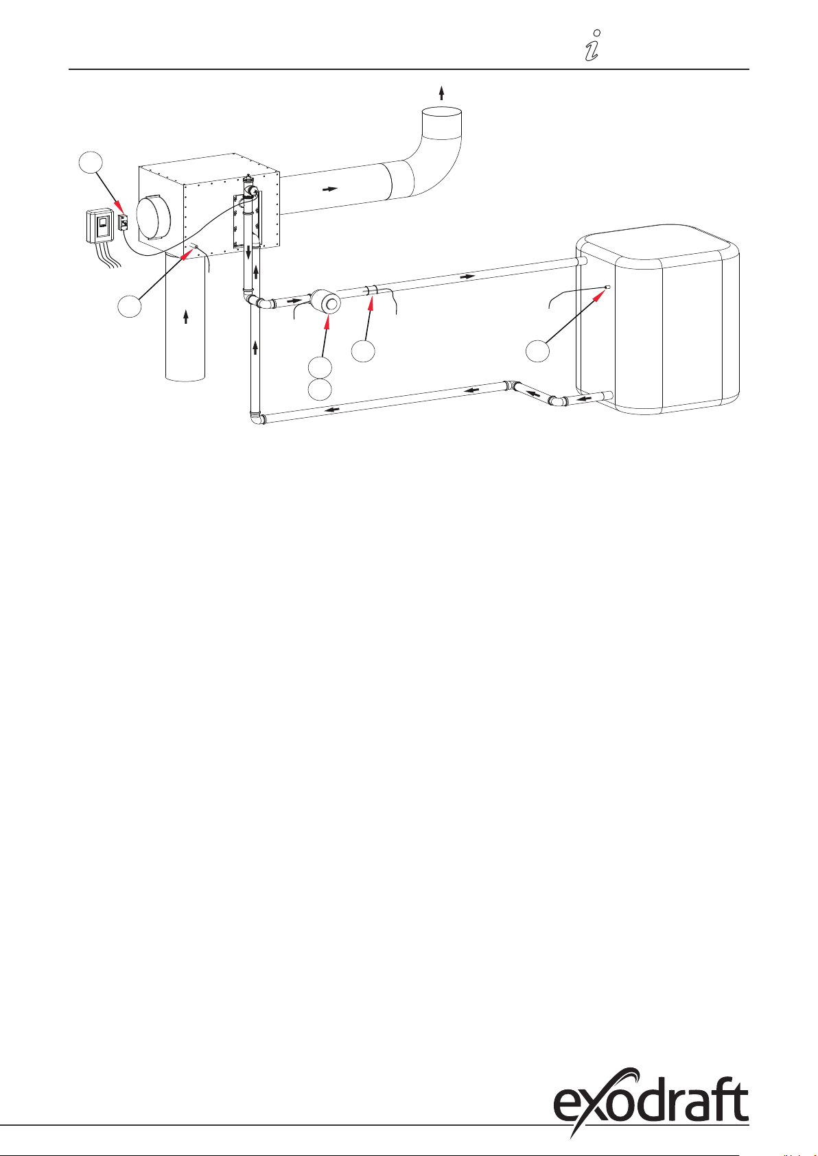
This diagram shows the following system:
Heat exchanger without bypass damper. One storage tank and a 0-10 V regulated circulator pump.
The S8 temperature sensor must be positioned in the heat exchanger inlet.
The S3 temperature sensor must be mounted on the forward ow pipe immediately after the heat exchanger.
The S1 temperature sensor must be mounted in the storage tank.
Important:
An STL thermostat which turns o the burner must be mounted on the forward ow pipe. The forward ow
temperature must not exceed 100°C.
Page 27
3110086 EHC20 UK 110515
S3
R1
V1
S1
A1
S8
Connection diagrams • 27
Page 28
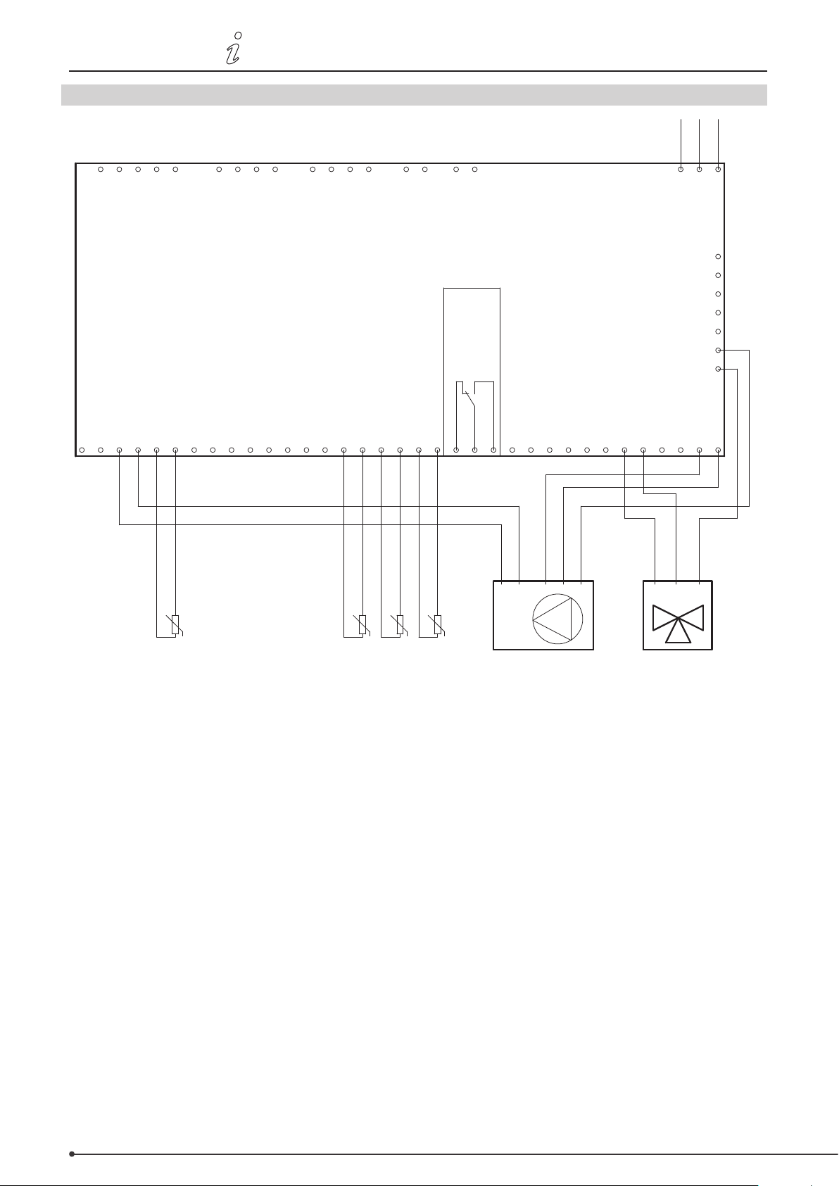
28 • Connection diagrams
3110086 EHC20 UK 110515
O.2 Program 6.1.2. Heat exchanger without bypass damper. With two storage tanks.
N
L1
PE
0-10V output
RC plugs
0-10V output
1 111 12 2222 3 3 34 44 5
1 111 12 2222 3 3 34 44 5
VFS2 sensors
CAN
VFS1 sensors
CAN
exodraft EHC10/EHC20 controller
PF relay
Temperature sensor input 7
Temperature sensor input 6
Temperature sensor input 5
Temperature sensor input 4
Temperature sensor input 3
Temperature sensor input 2
Temperature sensor input 8
Temperature sensor input 1
CGND GNDGND GNDGND GND GNDGNDGND GND
CGND GNDGND GNDGND GND GNDGNDGND GND
Relay output 6
Relay output 5
N NN
N NN
Relay output 4
Relay output 3
L
N
PE
L
N
PE
Mains
PE
PE
PE
PE
PE
PE
PE
PE
PE
PE
PE
PE
PE
PE
Relay output 2
Relay output 1
NNNNC NO
R1R2R3R4R5R6S1S2S3S4S5S6S7S 8V1V2
NNNNC NO
R1R2R3R4R5R6S1S2S3S4S5S6S7S 8V1V2
L N
L N
PE
U
-S8
Smoke gas temperature
U
-S3
-S2
temperature
Forward flow
U
-S1
temperature 2
Storage tank
U
Storage tank
temperature 1
0-10V
0-10V
GND/0V
GND/0V
PE
Pump 3-way valve
L N PEL N PE
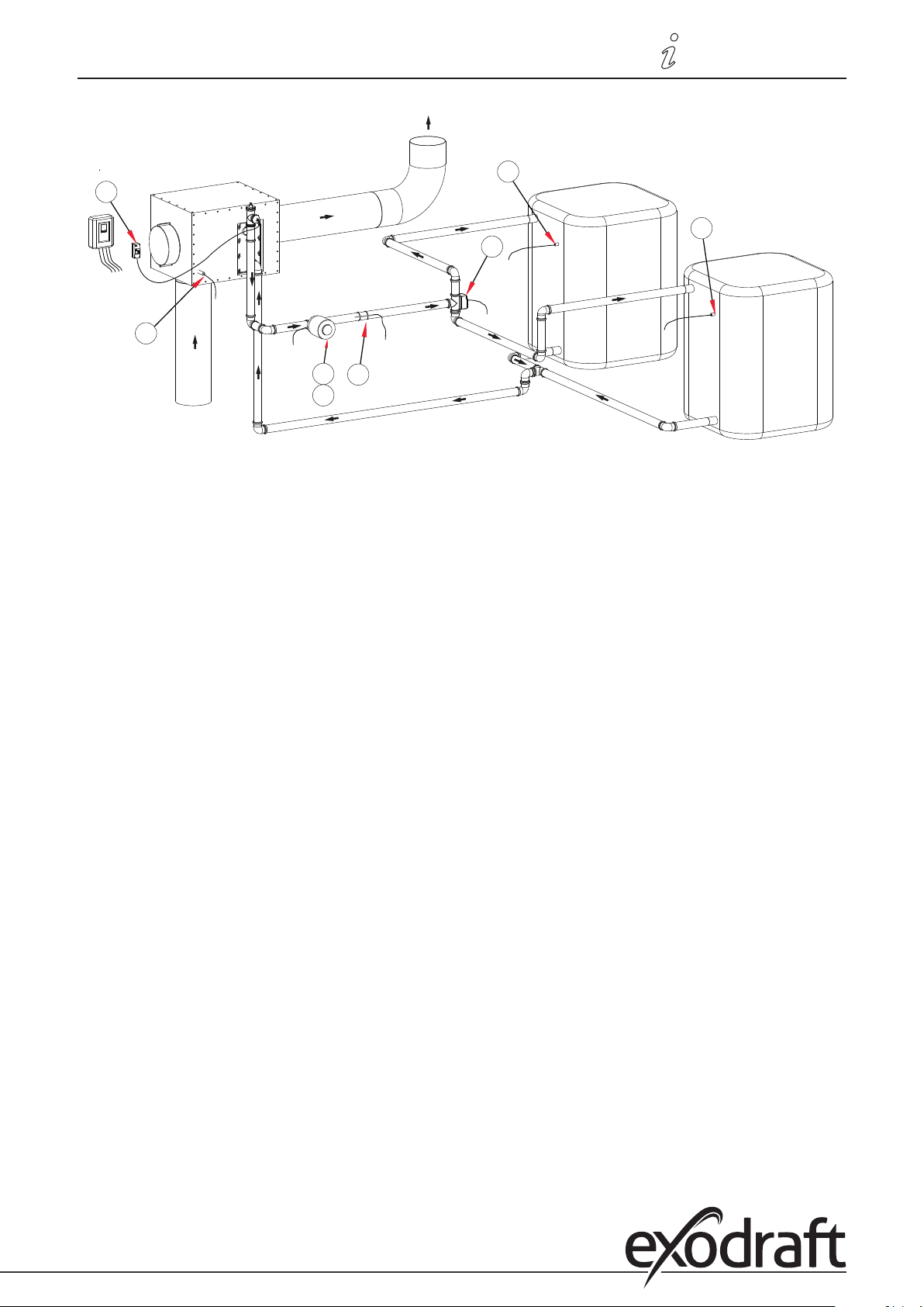
This diagram shows the following system:
Heat exchanger without bypass damper. Two storage tanks, a 3-way valve and a 0-10 V regulated circulator pump.
The S8 temperature sensor must be positioned in the heat exchanger inlet.
The S3 temperature sensor must be mounted on the forward ow pipe immediately after the heat exchanger.
The S2 temperature sensor must be mounted in storage tank #2.
The S1 temperature sensor must be mounted in storage tank #1.
Important:
An STL thermostat which turns o the burner must be mounted on the forward ow pipe. The forward ow
temperature must not exceed 100°C.
Page 29
3110086 EHC20 UK 110515
A1
S8
R1
V1
Connection diagrams • 29
S1
S2
R3
S3
Page 30
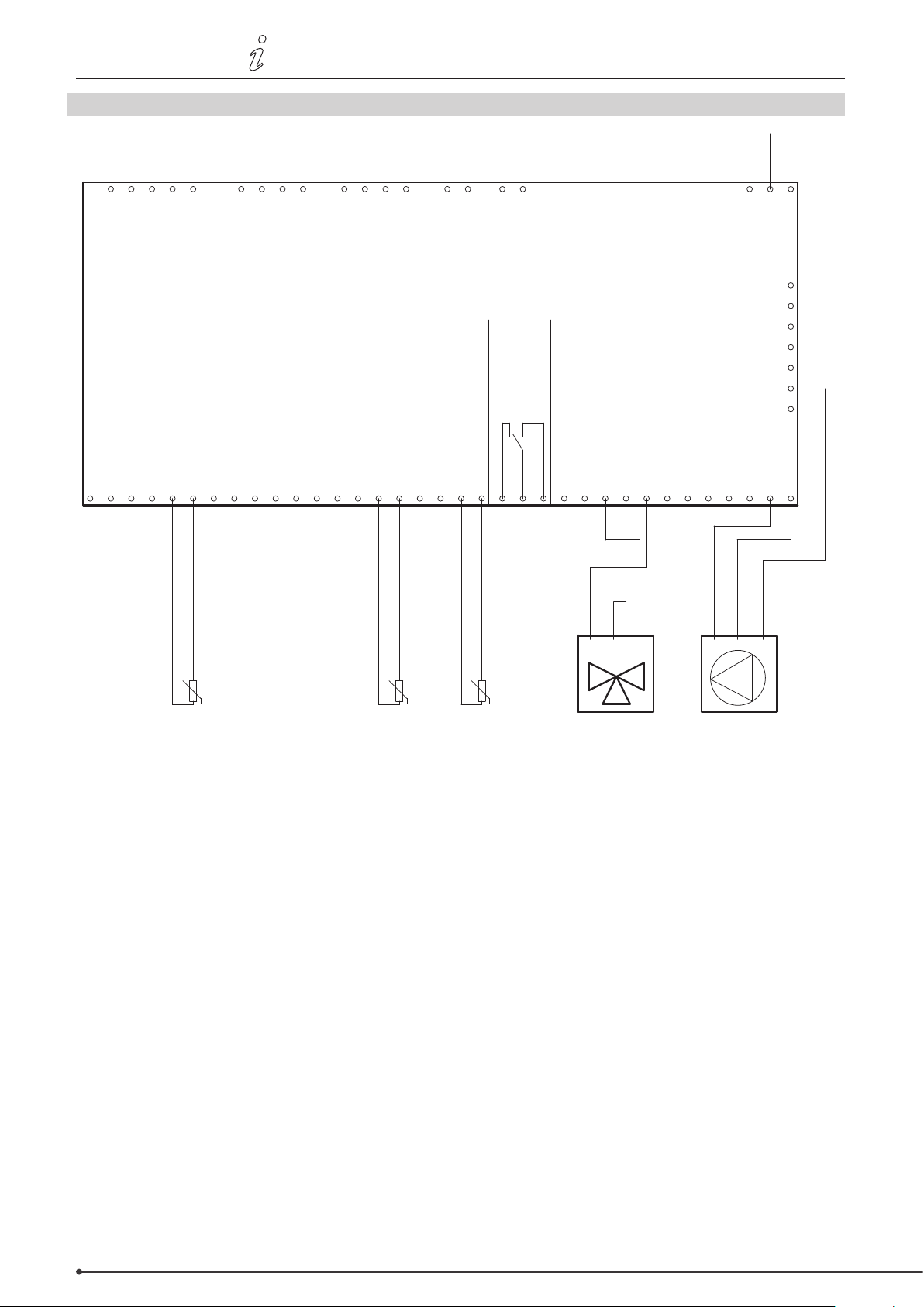
30 • Connection diagrams
temperature
3110086 EHC20 UK 110515
O.3 Program 6.1.3 Heat exchanger without bypass damper. With one storage tank and a mixer.
N
L1
PE
0-10V output
RC plugs
0-10V output
1 111 12 2222 3 3 34 44 5
1 111 12 2222 3 3 34 44 5
VFS2 sensors
CAN
VFS1 sensors
CAN
exodraft EHC10/EHC20 controller
PF relay
Temperature sensor input 8
Temperature sensor input 7
Temperature sensor input 6
Temperature sensor input 5
Temperature sensor input 4
Temperature sensor input 3
Temperature sensor input 1
Temperature sensor input 2
Relay output 6
Relay output 5
CGND GNDGND GNDGND GND GNDGNDGND GND
CGND GNDGND GNDGND GND GNDGNDGND GND
N NN
N NN
CCWCW N CCWCW N
Relay output 3
Relay output 4
L
L
L
N
PE
L
N
PE
Mains
PE
PE
PE
PE
PE
PE
PE
PE
PE
PE
PE
PE
PE
PE
Relay output 1
Relay output 2
NNNNC NO
R1R2R3R4R5R6S1S2S3S4S5S6S7S 8V1V2
NNNNC NO
R1R2R3R4R5R6S1S2S3S4S5S6S7S 8V1V2
N
N
PE
PE
U
-S8
Smoke gas temperature Forward flow
-S3
temperature
U
Storage tank
-S1
U
Mixer Pump
This diagram shows the following system:
Heat exchanger without bypass damper. One storage tank, a mixer and a circulator pump.
The S8 temperature sensor must be positioned in the heat exchanger inlet.
The S3 temperature sensor must be mounted on the forward ow pipe immediately after the heat exchanger.
The S1 temperature sensor must be mounted in the storage tank.
The mixer should be controlled in such a way that R4 is enabled when the temperature in the forward ow pipe needs
to increase. R5 is enabled when the temperature needs to decrease.
Important:
An STL thermostat which turns o the burner must be mounted on the forward ow pipe. The forward ow
temperature must not exceed 100°C.
Page 31
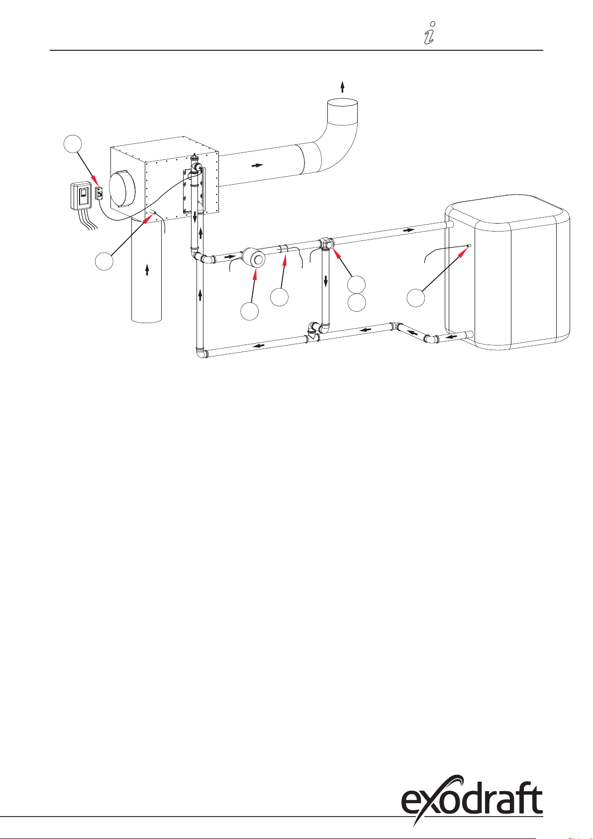
3110086 EHC20 UK 110515
S3
R1
S1
S8
R4
R5
A1
Connection diagrams • 31
Page 32
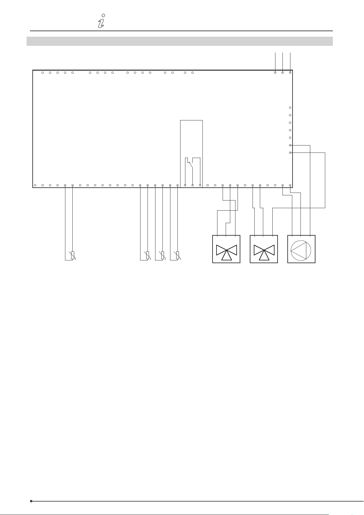
32 • Connection diagrams
3110086 EHC20 UK 110515
O.4 Program 6.1.4. Heat exchanger without bypass damper. With two storage tanks and a mixer.
N
L1
PE
0-10V output
RC plugs
0-10V output
1 111 12 2222 3 3 34 44 5
1 111 12 2222 3 3 34 44 5
VFS2 sensors
CAN
VFS1 sensors
CAN
exodraft EHC10/EHC20 controller
PF relay
Temperature sensor input 7
Temperature sensor input 6
Temperature sensor input 5
Temperature sensor input 4
Temperature sensor input 3
Temperature sensor input 2
Temperature sensor input 8
Temperature sensor input 1
CGND GNDGND GNDGND GND GNDGNDGND GND
CGND GNDGND GNDGND GND GNDGNDGND GND
Relay output 6
Relay output 5
N NN
N NN
Relay output 4
Relay output 3
CCWCW N
CCWCW N
L N PEL N PE
L
N
PE
L
N
PE
Mains
PE
PE
PE
PE
PE
PE
PE
PE
PE
PE
PE
PE
PE
PE
Relay output 2
Relay output 1
NNNNC NO
R1R2R3R4R5R6S1S2S3S4S5S6S7S8V1V2
NNNNC NO
R1R2R3R4R5R6S1S2S3S4S5S6S7S8V1V2
N
N
L
L
PE
PE
U
-S8
Smoke gas temperature
U
-S3
temperature
Forward flow
-S2
temperature 2
Storage tank
U
-S1
Storage tank
temperature 1
U
Mixer Pump3-way valve
This diagram shows the following system:
Heat exchanger without bypass damper. One storage tank, a mixer and a circulator pump.
The S8 temperature sensor must be positioned in the heat exchanger inlet.
The S3 temperature sensor must be mounted on the forward ow pipe immediately after the heat exchanger.
The S2 temperature sensor must be mounted in storage tank #2.
The S1 temperature sensor must be mounted in storage tank #1.
The mixer should be controlled in such a way that R4 is enabled when the temperature in the forward ow pipe needs
to increase. R5 is enabled when the temperature needs to decrease.
Important:
An STL thermostat which turns o the burner must be mounted on the forward ow pipe. The forward ow
temperature must not exceed 100°C.
Page 33
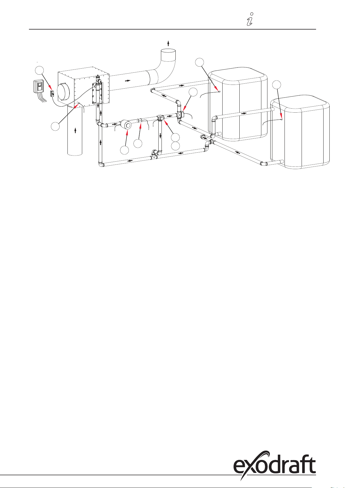
3110086 EHC20 UK 110515
S1
R1
S2
R3
S8
R4
R5
S3
A1
Connection diagrams • 33
Page 34
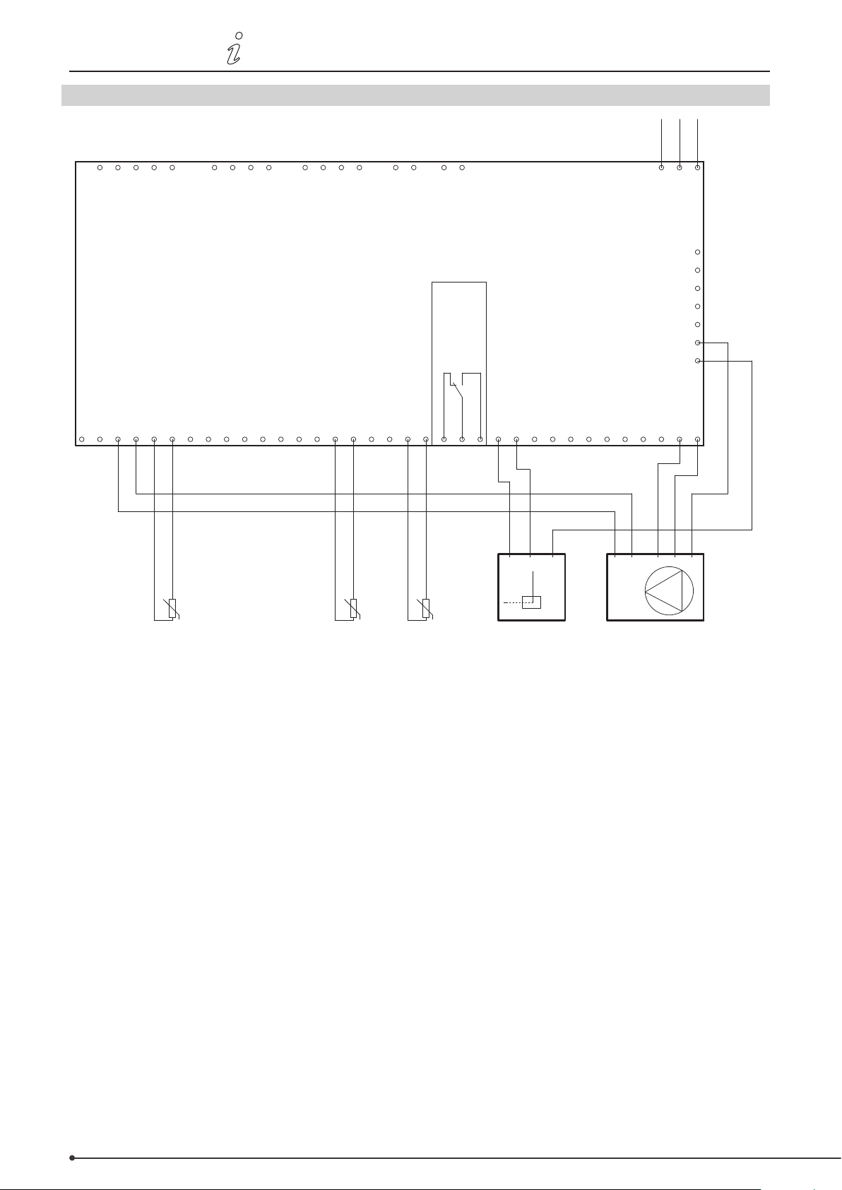
34 • Connection diagrams
3110086 EHC20 UK 110515
O.5 Program 6.1.5. Heat exchanger with bypass damper. With one storage tank.
N
L1
PE
0-10V output
RC plugs
0-10V output
1 111 12 2222 3 3 34 44 5
1 111 12 2222 3 3 34 44 5
VFS2 sensors
CAN
VFS1 sensors
CAN
exodraft EHC10/EHC20 controller
PF relay
Temperature sensor input 7
Temperature sensor input 6
Temperature sensor input 5
Temperature sensor input 4
Temperature sensor input 3
Temperature sensor input 2
Temperature sensor input 8
Temperature sensor input 1
CGND GNDGND GNDGND GND GNDGNDGND GND
CGND GNDGND GNDGND GND GNDGNDGND GND
Relay output 6
N NN
N NN
N
N
L
L
Relay output 5
Relay output 4
Relay output 3
PE
PE
0-10V
0-10V
GND/0V
GND/0V
L
N
PE
L
N
PE
Mains
PE
PE
PE
PE
PE
PE
PE
PE
PE
PE
PE
PE
PE
PE
Relay output 2
Relay output 1
NNNNC NO
R1R2R3R4R5R6S1S2S3S4S5S6S7S8V1V2
NNNNC NO
R1R2R3R4R5R6S1S2S3S4S5S6S7S8V1V2
L N
L N
PE
PE
U
-S8
Smoke gas temperature Forward flow
-S3
temperature
U
Storage tank
temperature
-S1
U
PumpBypass
This diagram shows the following system:
Heat exchanger with bypass damper. One storage tank and a 0-10 V regulated circulator pump.
The S8 temperature sensor must be positioned in the heat exchanger inlet.
The S3 temperature sensor must be mounted on the forward ow pipe immediately after the heat exchanger.
The S1 temperature sensor must be mounted in the storage tank.
R6 is enabled when the bypass damper is to switch to the non-bypass position.
Important:
An STL thermostat which turns o the burner must be mounted on the forward ow pipe. The forward ow
temperature must not exceed 100°C.
Page 35
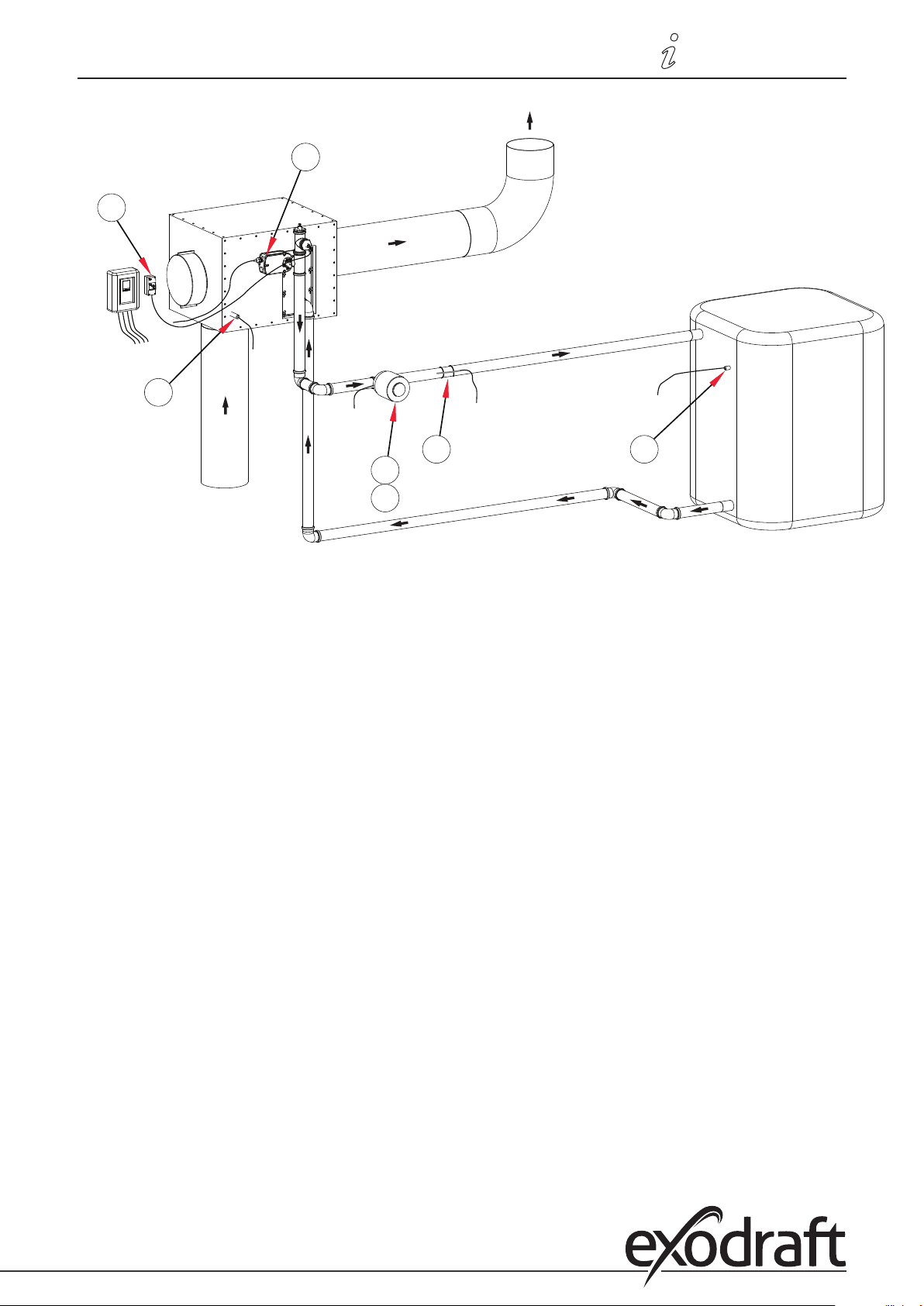
3110086 EHC20 UK 110515
S3
R1
S1
R6
S8
V1
A1
Connection diagrams • 35
Page 36
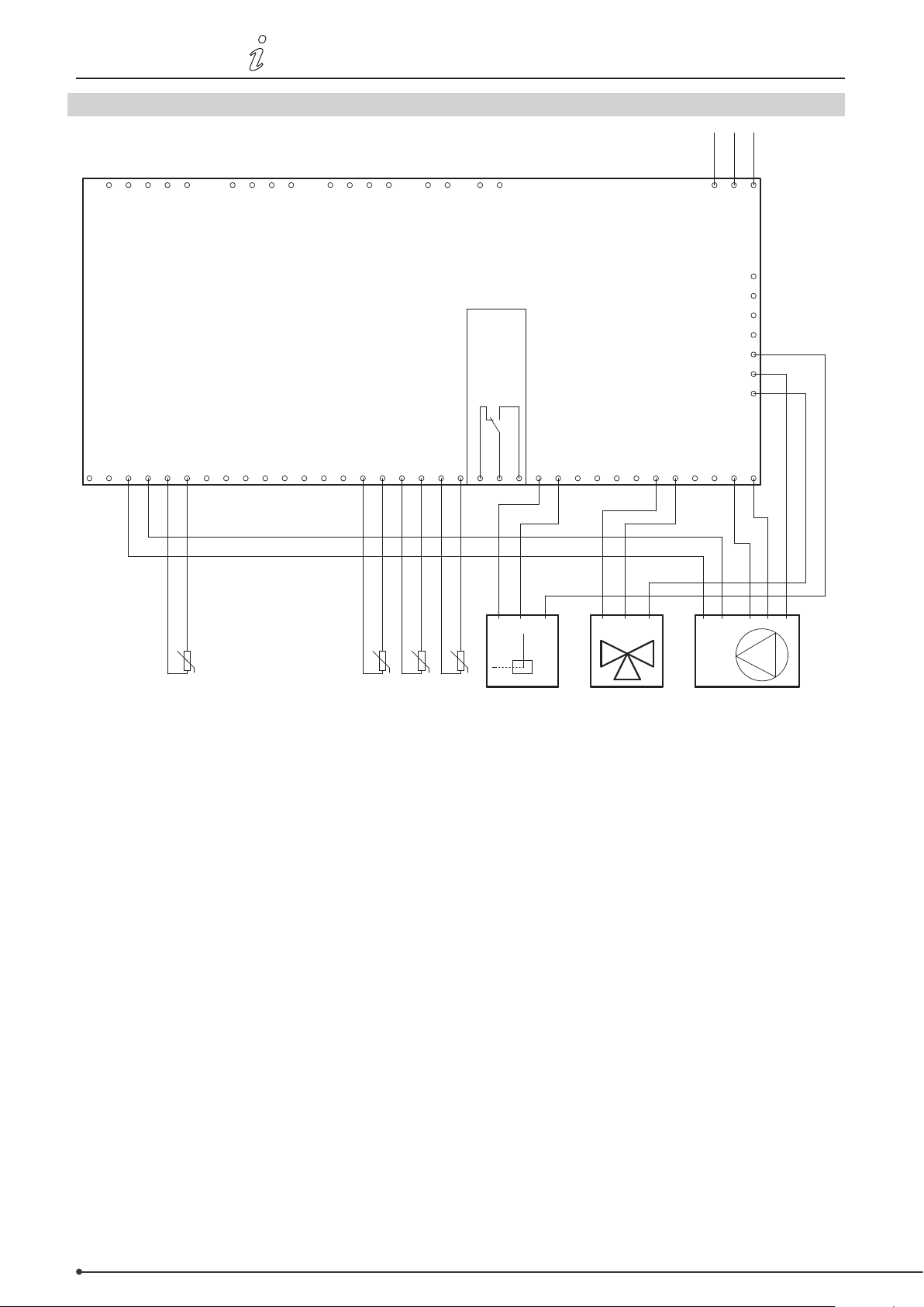
36 • Connection diagrams
3110086 EHC20 UK 110515
O.6 Program 6.1.6. Heat exchanger with bypass damper. With two storage tanks.
N
L1
PE
0-10V output
RC plugs
0-10V output
1 111 12 2222 3 3 34 44 5
1 111 12 2222 3 3 34 44 5
VFS2 sensors
CAN
VFS1 sensors
CAN
exodraft EHC10/EHC20 controller
PF relay
Temperature sensor input 7
Temperature sensor input 6
Temperature sensor input 5
Temperature sensor input 4
Temperature sensor input 3
Temperature sensor input 2
Temperature sensor input 8
Temperature sensor input 1
Relay output 6
Relay output 5
Relay output 4
Relay output 3
CGND GNDGND GNDGND GND GNDGNDGND GND
CGND GNDGND GNDGND GND GNDGNDGND GND
L
L
N NN
N NN
N
N
PE
PE
L N PE
L N PE
L
N
PE
L
N
PE
Mains
PE
PE
PE
PE
PE
PE
PE
PE
PE
PE
PE
PE
PE
PE
Relay output 2
Relay output 1
NNNNC NO
R1R2R3R 4R5R6S1S2S3S4S5S6S7S8V1V2
NNNNC NO
R1R2R3R 4R5R6S1S2S3S4S5S6S7S8V1V2
L N
L N
PE
0-10V
0-10V
GND/0V
GND/0V
PE
U
-S8
Smoke gas temperature
U
-S3
temperature
Forward flow
-S2
temperature 2
Storage tank
U
-S1
Storage tank
U
Pump3-way valveBypass
temperature 1
This diagram shows the following system:
Heat exchanger with bypass damper. Two storage tanks, a 3-way valve and a circulator pump.
The S8 temperature sensor must be positioned in the heat exchanger inlet.
The S3 temperature sensor must be mounted on the forward ow pipe immediately after the heat exchanger.
The S2 temperature sensor must be mounted in storage tank #2.
The S1 temperature sensor must be mounted in storage tank #1.
R6 is enabled when the bypass damper is to switch to the non-bypass position.
Important:
An STL thermostat which turns o the burner must be mounted on the forward ow pipe. The forward ow
temperature must not exceed 100°C.
Page 37
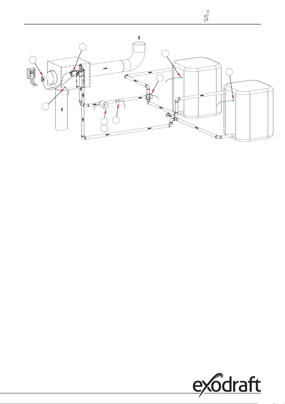
3110086 EHC20 UK 110515
S1
R1
S2
R3
R6
S8
S3
V1
A1
Connection diagrams • 37
Page 38
38 • Connection diagrams
3110086 EHC20 UK 110515
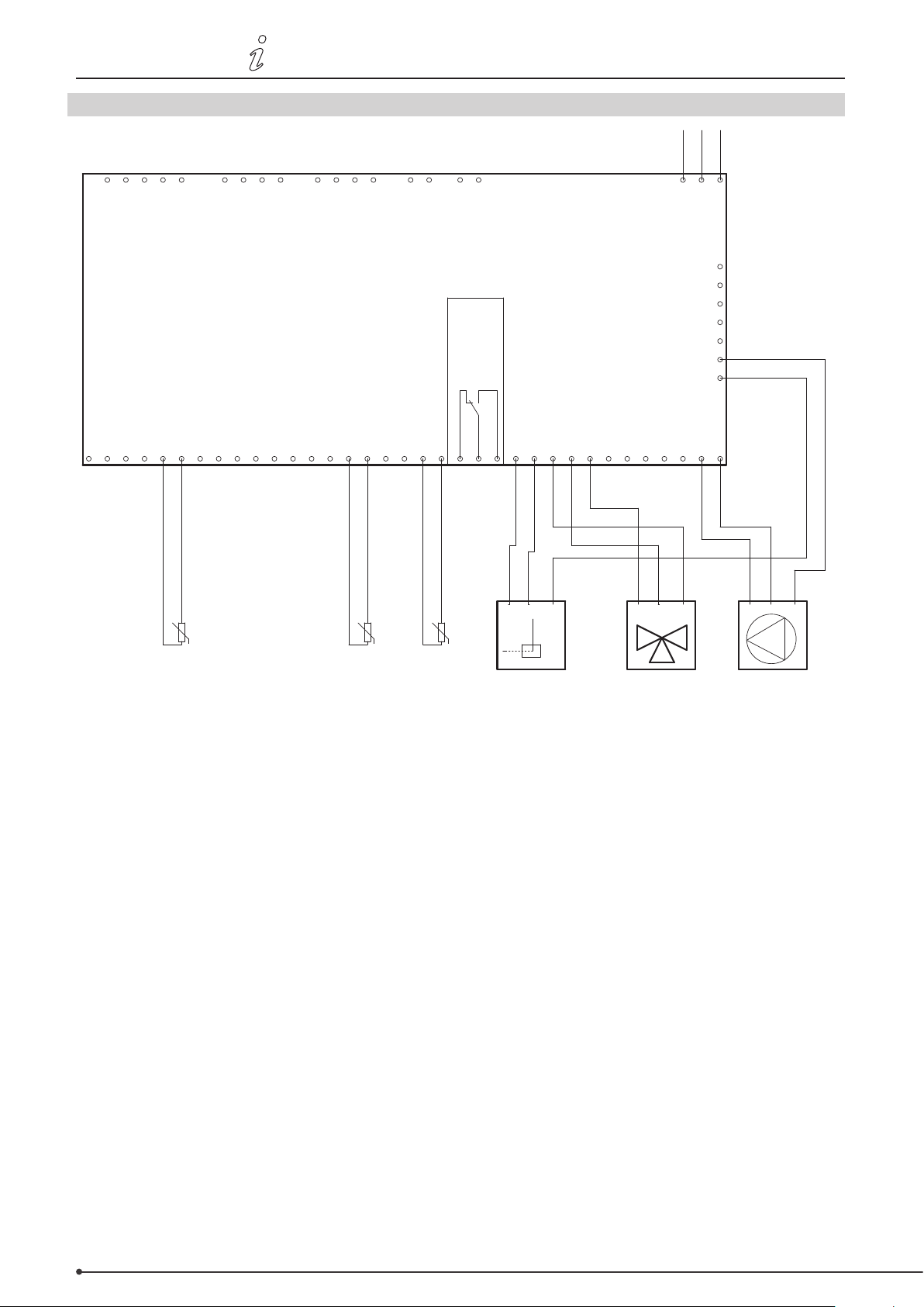
O.7 Program 6.1.7. Heat exchanger with bypass damper. With one storage tank and a mixer.
N
L1
PE
0-10V output
RC plugs
0-10V output
1 111 12 2222 3 3 34 44 5
1 111 12 2222 3 3 34 44 5
VFS2 sensors
CAN
VFS1 sensors
CAN
exodraft EHC10/EHC20 controller
PF relay
Temperature sensor input 5
Temperature sensor input 4
Temperature sensor input 3
Temperature sensor input 2
Temperature sensor input 7
Temperature sensor input 8
Temperature sensor input 6
Temperature sensor input 1
CGND GNDGND GNDGND GND GNDGNDGND GND
CGND GNDGND GNDGND GND GNDGNDGND GND
L
L
Relay output 6
N
N
Relay output 5
N NN
N NN
Black
PE
PE
Blue
Relay output 4
Brown
Relay output 3
L
N
PE
L
N
PE
Mains
PE
PE
PE
PE
PE
PE
PE
PE
PE
PE
PE
PE
PE
PE
Relay output 2
Relay output 1
NNNNC NO
R1R2R3R4R5R6S1S2S3S4S5S6S7S8V1V2
NNNNC NO
R1R2R3R4R5R6S1S2S3S4S5S6S7S8V1V2
N
N
L
L
PE
CCWCW N CCWCW N
PE
U
-S8
Smoke gas temperature Forward flow
-S3
temperature
U
Storage tank
-S1
temperature
U
MixerBypass Pump
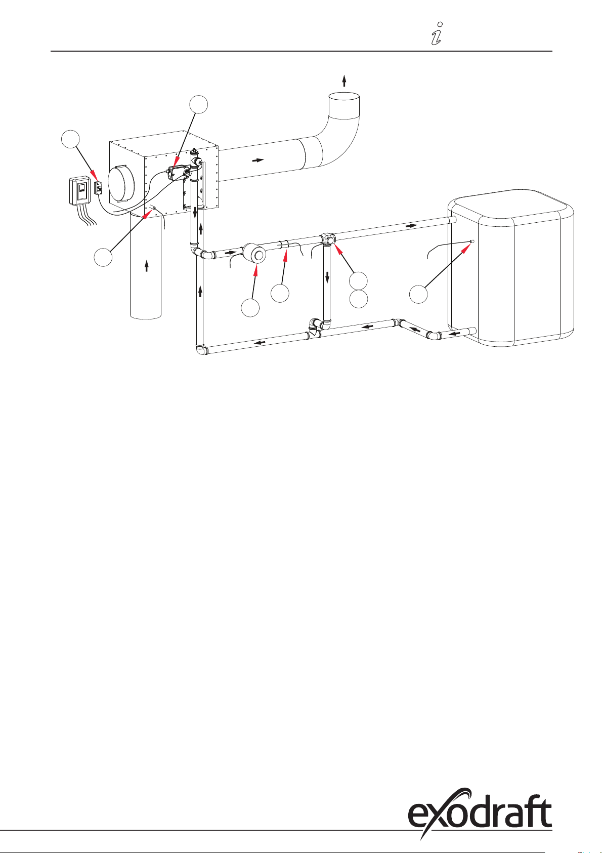
This diagram shows the following system:
Heat exchanger with bypass damper. One storage tank, a mixer and a circulator pump.
The S8 temperature sensor must be positioned in the heat exchanger inlet.
The S3 temperature sensor must be mounted on the forward ow pipe immediately after the heat exchanger.
The S1 temperature sensor must be mounted in storage tank #1.
The mixer should be controlled in such a way that R4 is enabled when the temperature in the forward ow pipe needs
to increase. R5 is enabled when the temperature needs to decrease.
R6 is enabled when the bypass damper is to switch to the non-bypass position.
Important:
An STL thermostat which turns o the burner must be mounted on the forward ow pipe. The forward ow
temperature must not exceed 100°C.
Page 39
3110086 EHC20 UK 110515
R1
S1
R6
S8
R4
R5
S3
A1
Connection diagrams • 39
Page 40
40 • Connection diagrams
L1
N
PE
3110086 EHC20 UK 110515
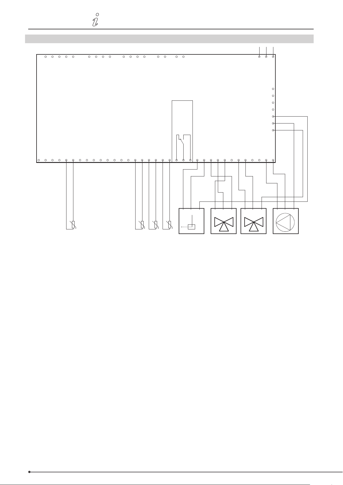
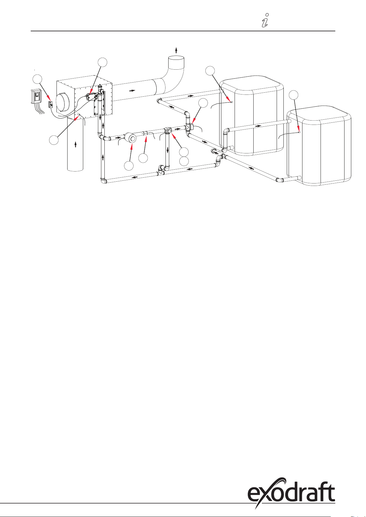
O.8 Program 6.1.8. Heat exchanger with bypass damper. With two storage tanks and a mixer.
0-10V output
RC plugs
0-10V output
1 111 12 2222 3 3 34 44 5
1 111 12 2222 3 3 34 44 5
Temperature sensor input 7
Temperature sensor input 8
VFS2 sensors
Temperature sensor input 6
L
N
PE
L
N
PE
CAN
VFS1 sensors
Temperature sensor input 5
Temperature sensor input 4
Temperature sensor input 3
Temperature sensor input 2
CAN
exodraft EHC10/EHC20 controller
PF relay
Temperature sensor input 1
CGND GNDGND GNDGND GND GNDGNDGND GND
CGND GNDGND GNDGND GND GNDGNDGND GND
N
N
L
L
Relay output 6
PE
PE
Relay output 5
N NN
N NN
Mains
PE
PE
PE
PE
PE
PE
PE
PE
PE
PE
PE
PE
PE
PE
Relay output 4
Relay output 3
Relay output 2
Relay output 1
NNNNC NO
R1R2R3R4R5R6S1S2S3S4S5S6S7S8V1V2
NNNNC NO
R1R2R3R4R5R6S1S2S3S4S5S6S7S8V1V2
N
N
L
L
PE
L N PE
CCWCW N
L N PE
CCWCW N
PE
U
-S8
Smoke gas temperature
This diagram shows the following system:
U
-S3
temperature
Forward flow
-S2
temperature 2
Storage tank
U
-S1
Storage tank
U
Bypass 3-way valve PumpMixer
temperature 1
Heat exchanger with bypass damper. Two storage tanks, a mixer, a 3-way valve and a circulator pump.
The S8 temperature sensor must be positioned in the heat exchanger inlet.
The S3 temperature sensor must be mounted on the forward ow pipe immediately after the heat exchanger.
The S2 temperature sensor must be mounted in storage tank #2.
The S1 temperature sensor must be mounted in storage tank #1.
The mixer should be controlled in such a way that R4 is enabled when the temperature in the forward ow pipe needs
to increase. R5 is enabled when the temperature needs to decrease.
R6 is enabled when the bypass damper is to switch to the non-bypass position.
Important:
An STL thermostat which turns o the burner must be mounted on the forward ow pipe. The forward ow
temperature must not exceed 100°C.
Page 41
3110086 EHC20 UK 110515
S1
R1
S2
R3
R6
S8
R4
R5
S3
A1
Connection diagrams • 41
Page 42
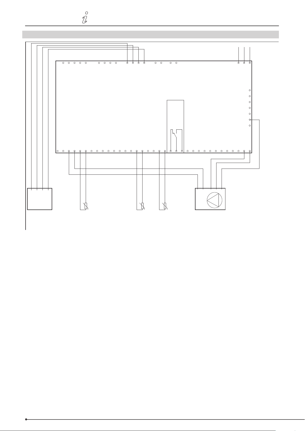
42 • Connection diagrams
Smoke gas temperature Forward flow
temperature
Storage tank
temperature
Temp.
Flow0V+5V
Temperature sensor input 8
VFS2 sensors
VFS1 sensors
Mains
0-10V output
0-10V output
exodraft EHC10/EHC20 controller
PF relay
Relay output 6
Relay output 1
RC plugs
CAN
CAN
Temperature sensor input 7
Temperature sensor input 6
Temperature sensor input 5
Temperature sensor input 4
Temperature sensor input 3
Temperature sensor input 2
Temperature sensor input 1
Relay output 5
Relay output 4
Relay output 3
Relay output 2
PumpVFS-Sensor
1 111 12 2222 3 3 34 44 5
CGND GNDGND GNDGND GND GNDGNDGND GND
L
N NN
N
NNNNC NO
PE
PE
PE
PE
PE
PE
PE
PE
R1R2R3R4R5R6S1S2S3S 4S5S6S7S8V1V2
1 111 12 2222 3 3 34 44 5
CGND GNDGND GNDGND GND GNDGNDGND GND
L
N NN
N
NNNNC NO
PE
PE
PE
PE
PE
PE
PE
PE
R1R2R3R4R5R6S1S2S3S4S5S6S7S8V1V2
0-10V
GND/0V
L N
PE
0-10V
GND/0V
L N
PE
1 2 3 4
1 2 3 4
U
-S3
U
-S3
U
-S8
L1
N
PE
3110086 EHC20 UK 110515
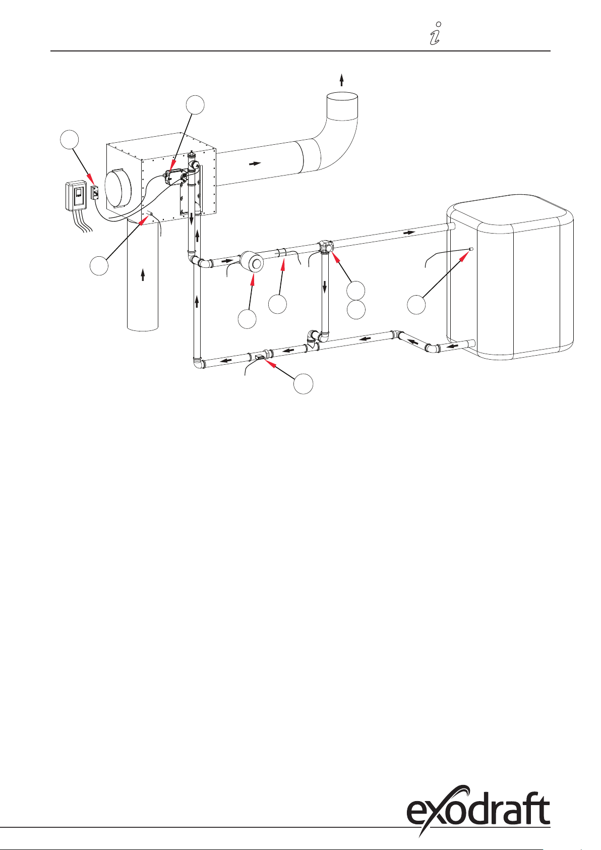
O.9 Program 6.1.1. Heat exchanger with VFS sensor for power measurement.
This diagram shows the following system:
Heat exchanger with bypass damper. Two storage tanks, a mixer, a 3-way valve and a circulator pump.
The S8 temperature sensor must be positioned in the heat exchanger inlet.
The S3 temperature sensor must be mounted on the forward ow pipe immediately after the heat exchanger.
The S1 temperature sensor must be mounted in storage tank #1.
VFS sensor
Important:
An STL thermostat which turns o the burner must be mounted on the forward ow pipe. The forward ow
temperature must not exceed 100°C.
Page 43
3110086 EHC20 UK 110515
R1
S1
R6
S8
R4
R5
VFS
S3
A1
Connection diagrams • 43
Page 44
44 • Menu sequence and structure
P. Operation
P.1 Display and entry system
(1)
(2)
(3)
3110086 EHC20 UK 110515
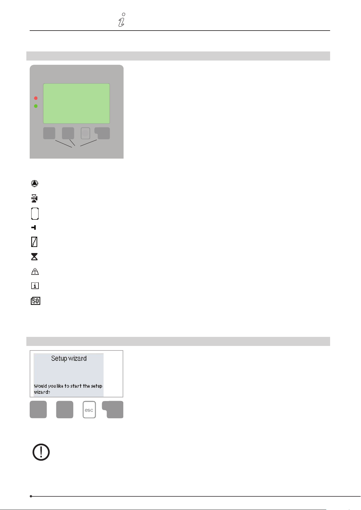
The display (1) with an extensive text and graphics mode makes the
controller virtually self-explanatory in use.
To access the settings from the overview, press the "esc" button.
The green status LED (2) lights up as soon as a relay is connected; the
red LED ashes in the event of an error message.
Entries are made using four buttons (3+4) which perform dierent
functions depending on the situation. The "esc" button (3) is used to
cancel an entry or exit a menu.
(4)
Example display symbols:
Pump (rotates when operating)
Valve (direction of ow in black)
Storage tank
Temperature sensor
Heat exchanger
Filling delay (see Filling time)
Warning / error message
New information
Logging enabled
Further symbols are used for the
special functions
You may then be prompted to conrm that you wish to save your
changes.
The functions of the other three buttons (4) are explained in the
area of the display directly above the buttons. Generally speaking,
however, the right-hand button is used to make and conrm
selections.
Example button functions:
+/- =Increase/decreasevalues
▼/▲ =Scrolldown/upinamenu
Yes/No =Conrm/cancel
Info =Furtherinformation
Back =Returntopreviousdisplay
OK =Conrmselection
Conrm =Conrmsetting
P.2 Setup wizard
After switching the controller on for the rst time and setting the language
and time, you will be asked whether or not you would like to parametrise the
controller with the help of the setup wizard. However, the setup wizard can be
closed or launched again later on from the Special functions menu. The setup
wizard guides you through the necessary basic settings in the correct order and
provides brief descriptions of the various parameters in the display. Pressing
the ”esc” button takes you back to the previous value so that you can view the
selected setting again and adjust it if necessary. Pressing the ”esc” button more
than once takes you back step by step to the selection mode, thus cancelling
the setup wizard. You should now select ”Manual” in the Operating mode menu
(page 48) in order to test the switch output with the load connected and check the sensor values for plausibility. You
can
then switch to automatic operation.
Observe the explanations of the individual parameters on the following pages, and check
whether
further settings are necessary for your application.
Page 45
3110086 EHC20 UK 110515
Menu sequence and structure • 45
P.3 Unassisted setup
If you decide not to use the setup wizard, you should make the necessary settings in the following order:
• Menu 9. Language, page 66
• Menu 6.15 Time and date, page 65
• Menu 6.1 Program selection, page 50
• Menu 4. Settings, all values, page 48
• Menu 5. Protective functions, if changes needed, page 49
• Menu 6. Special functions, if further changes needed. page 50
You should now select ”Manual” in the operation mode menu, page 48 in order to test the switch outputs with the
load connected and check the sensor values for plausibility. You can then switch to automatic operation.
Observe the explanations of the individual parameters on the following pages, and check
whether further settings are necessary for your application.
exodraft recommends that you save the conguration on the SD card after the setup.
To save the conguration, you will need to use the “Save cong.” function. This can be found in Menu 6.14
(Special functions/SD card).
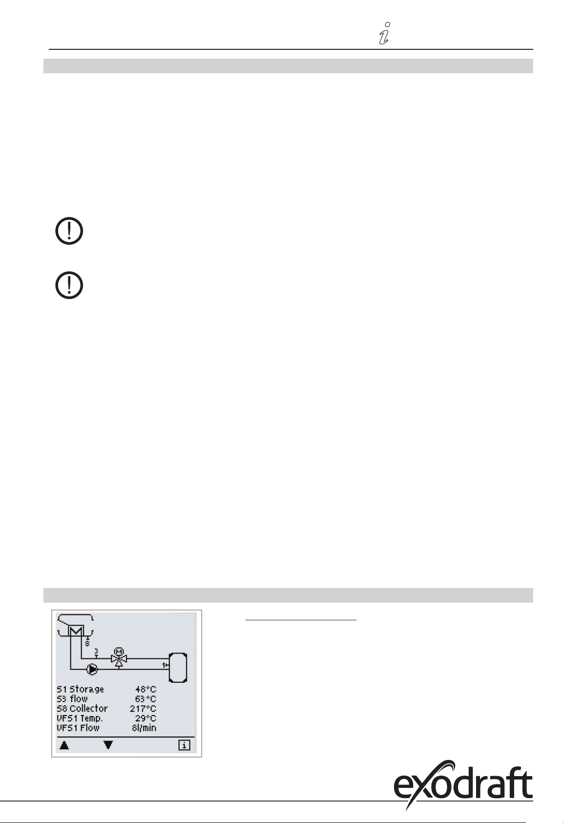
P.4 Menu sequence and structure
The graphics or overview mode appears when no button has been pressed
for two minutes or if the main menu is exited by pressing ”esc”.
Within this overview, you can scroll through the sensors and relays using
the up and down buttons.
Page 46
46 • Menu sequence and structure
3110086 EHC20 UK 110515
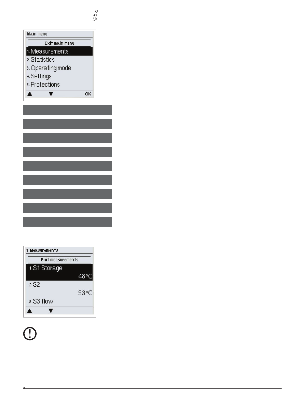
In graphics or overview mode, the esc button takes you straight to the
main menu. The following items are then available to choose from:
1. Measurements
2. Statistics
3. Operating mode
4. Settings
5. Protections
6. Special functions
7. Menu lock
8. Service data
9. Language
1. Measurements
Current temperature values with explanations
System function check with operating hours etc.
Automatic operation, manual operation or switch o device
Set parameters required for normal operation
Return cooling, anti-seize protection
Program selection, sensor calibration, clock, additional sensors etc.
Prevents accidental changes at critical points
For diagnostics in the event of an error
Select language
The ”1. Measurements” menu is used to display the temperatures currently
measured.
The menu can be exited by pressing ”esc” or selecting ”Exit measurements”.
If ”--” appears in the display instead of the measurement, this indicates a defective or incorrect temperature sensor.
If the cables are too long or the sensors are not positioned optimally, this can result in minor deviations in the
measurements. In this case, the display values can be corrected by entering the relevant information into the
controller. Follow the instructions under page 63.
What measurements are displayed depends on the selected program, the sensors connected and the specic
device design.
Page 47
3110086 EHC20 UK 110515
Menu sequence and structure • 47
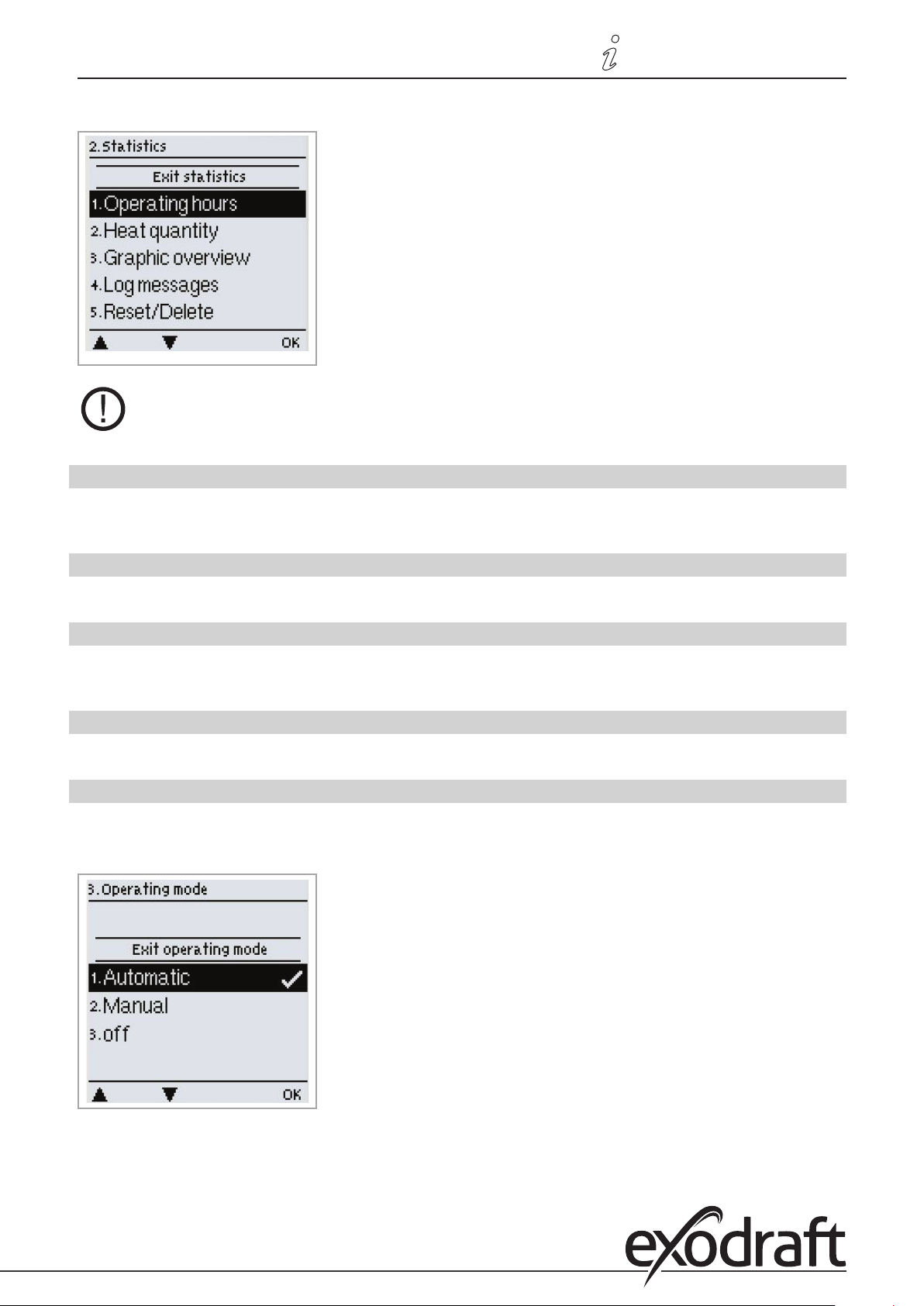
2. Statistics
The ”2. Statistics” menu is used for function control and long-term
monitoring of the system.
The menu can be exited by pressing ”esc” or selecting ”Exit statistics”.
In order to evaluate system data, the controller clock must be set correctly. Improper operation
or an incorrect time may result in data being deleted, recorded incorrectly or overwritten.
The manufacturer accepts no liability for the data recorded.
2.1 Operating hours
Shows the number of hours that the solar pump connected to the controller has been in operation. Various time ranges
(day-years) are available.
2.2 Heat quantity
Shows the system’s heat yield.
2.3 Graphic overview
The data set out under 2.1-2.2 are presented clearly in the form of a bar chart here. Various time ranges are available for
comparison. You can scroll using the two buttons on the left.
2.4 Reports
Shows the last 20 system reports issued along with details of the date and time.
2.5 Reset / delete
Allows you to reset and delete individual statistics. If you select ”All statistics”, everything apart from the error list will be deleted.
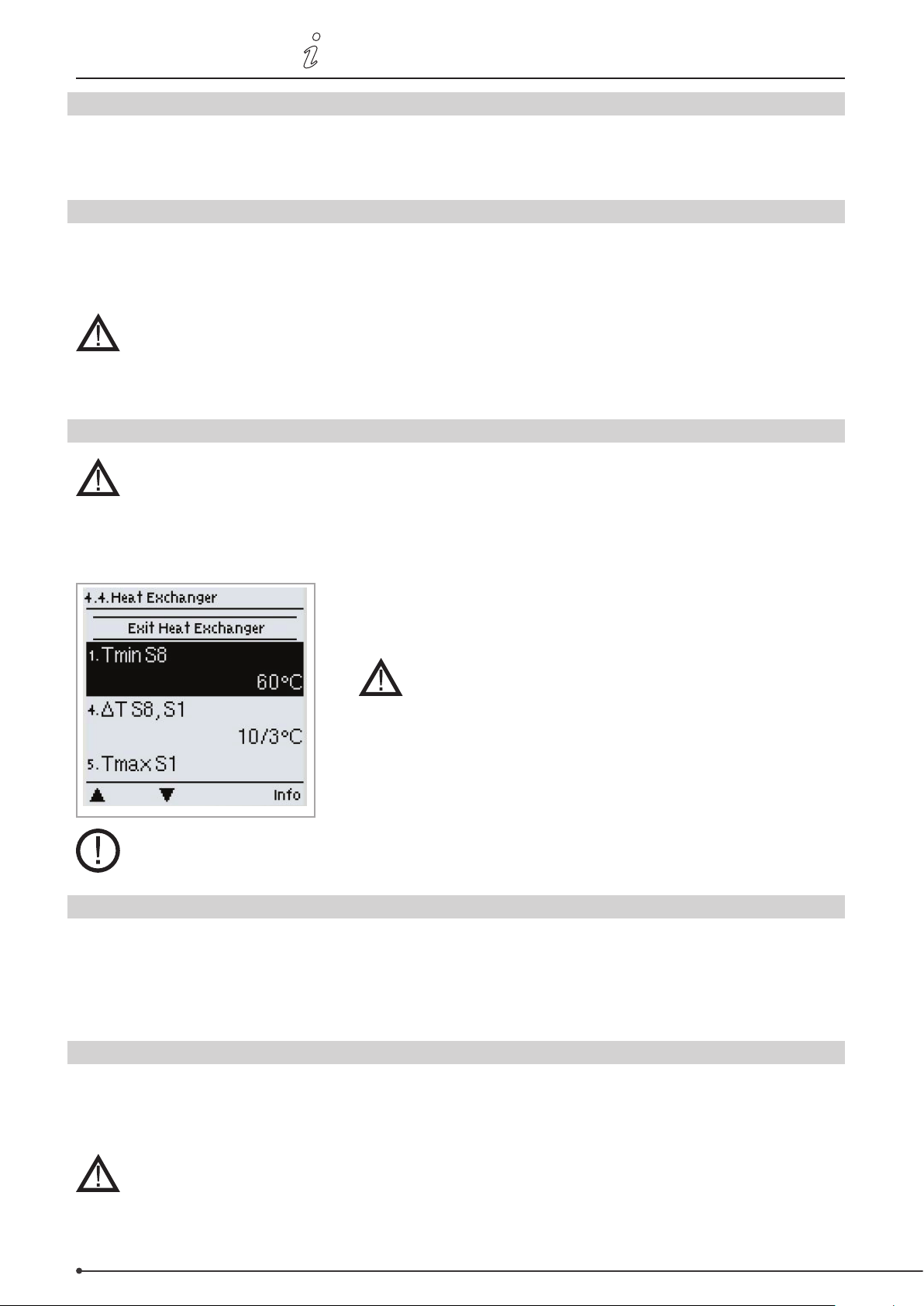
3. Operating mode
In the ”3. Operating mode” menu, you can not only select the automatic
mode but also switch o the controller or switch to a manual operating
mode.
You can exit the menu by pressing ”esc” or selecting ”Exit statistics”.
Page 48
48 • Menu sequence and structure
3110086 EHC20 UK 110515
3.1 Automatic
Automatic mode is the normal mode of operation for the controller. Only in automatic mode can the controller function
correctly, taking into account the current temperatures and the parameters set. If the power supply is interrupted, the
controller will automatically return to the last selected operating mode.
3.2 Manual
The relay and therefore the loads connected are switched on or o at the push of a button, without taking into account
the current temperatures and the parameters set. The temperatures measured are displayed for overview and function
control purposes.
If the “Manual” operating mode is selected, the current temperatures and parameters selected
no longer play any role. There is therefore a risk of scalding or serious damage to the system.
The “Manual” operating mode should only be used by specialists for brief function tests or
when setting up the controller.
3.3 O
If the “O” operating mode is enabled, all controller functions are switched o. This can cause
the solar collector or other system components to overheat. The temperatures measured
continue to be displayed for overview purposes.
4. Settings
In the ”4. Settings” menu, you can congure the basic settings for the
control functions.
Under no circumstances are these settings designed as
a substitute for the customer’s own safety provisions!
You can exit the menu by pressing ”esc” or selecting ”Exit settings”.
The menu numbering varies depending on the hydraulic schema chosen
(see “6.1 Program selection”, page 50 )
4.1 Tmin S (X)
Enable/switch-on temperature at sensor X
If this value is exceeded at the specied sensor and the other conditions are met, the controller will switch on the
associated pump or valve. If the temperature at the sensor then drops 5°C below this value, the pump or valve will be
switched o again.
Setting range: 0°C to 99°C / default: 20°C
4.2 Tmax S (X)
Switch-o temperature at sensor X
If this value is exceeded at the specied sensor, the controller will switch o the associated pump or valve. If this value is
then undershot at the sensor and the other conditions are met, the controller will switch on the pump or valve again.
Setting range: 0°C to 99°C / default: 60°C
Excessively high temperature settings can result in scalding or damage to the system.
The customer must make provisions to prevent scalding.
Page 49
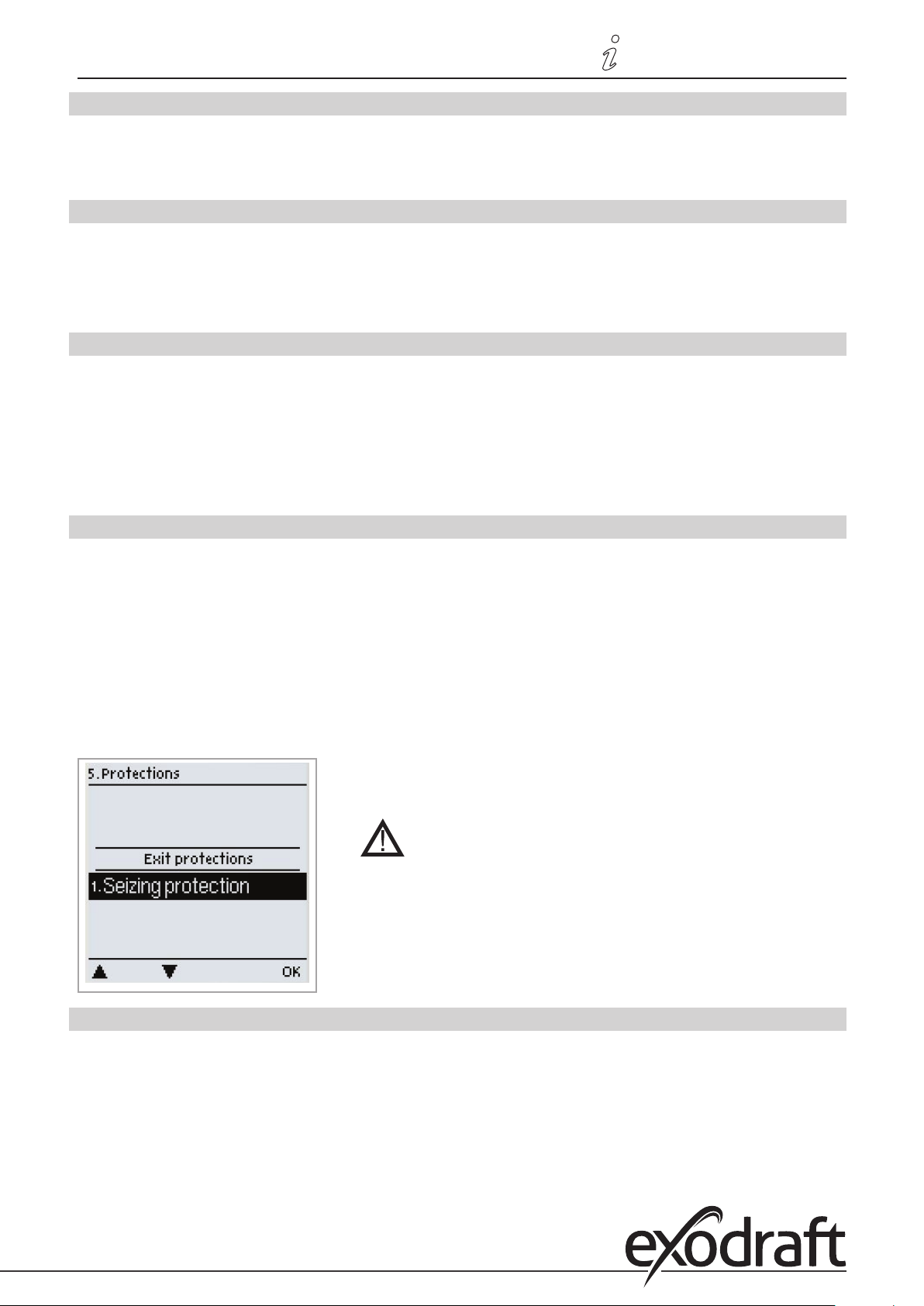
3110086 EHC20 UK 110515
Menu sequence and structure • 49
4.3 Priority S(X)
Priority of the storage tank X
This setting species the lling order. If an equal priority is set, the storage tanks will be lled on an equal basis.
Setting range: 1-4
4.4 T priority
Temperature threshold for absolute priority during primary lling
In multiple storage tank systems, the lling of a lower-ranking storage tank will not commence until the temperature
setpoint at the sensor for the higher-ranking storage tank is exceeded.
Setting range: 0°C to 90°C / default: 40°C
4.5 Filling time
Interrupting the lling of a lower-ranking storage tank
When a lower-ranking storage tank is being lled, a check to determine whether the collector has reached a
temperature level which would allow the higher-ranking storage tank to be lled is carried out after the period of time
set here. If this is the case, the higher-ranking storage tank will be lled again.
If this is not possible, the temperature rise will be measured (see ”4.6 Temperature rise”) in order to check whether the
collector will shortly allow the higher-ranking storage tank to be lled.
Setting range: 1 to 90 minutes / default: 20 minutes
4.6 Temperature rise
Extending the lling delay owing to temperature rise
In order to set the exact lling priorities for systems with multiple storage tanks, the minimum temperature rise at the
collector (measured over a minute) which is needed in order for the delay in lling the lower-ranking storage tank to be
extended by a minute is set. The delay is extended because the temperature rise at the collector will presumably soon
allow the higher-ranking storage tank to be lled. The lling of the primary storage tank will begin as soon as ∆T switchon conditions are met. If, however, the temperature rise undershoots the set value, the lling of the lower-ranking
storage tank will once again be enabled.
Setting range: 1°C to 10°C / default: 3°C
5. Protective functions
In the ”5. Protective functions” menu, you can enable and congure various
protective functions.
Under no circumstances are these settings designed
substitute for the customer’s own safety provisions.
You can exit the menu by pressing ”esc” or selecting ”Exit protective
functions”.
as a
5.1 Anti-seize protection
If anti-seize protection is enabled, the controller will switch on the relevant relay and the connected load for 5 seconds
every day at 12 o’ clock or every Sunday at 12 o’ clock in order to prevent the pump or the valve seizing as a result of
extended standstill periods.
R1 setting range: daily, weekly, o / default: O
R2 setting range: daily, weekly, o / default: O
Page 50
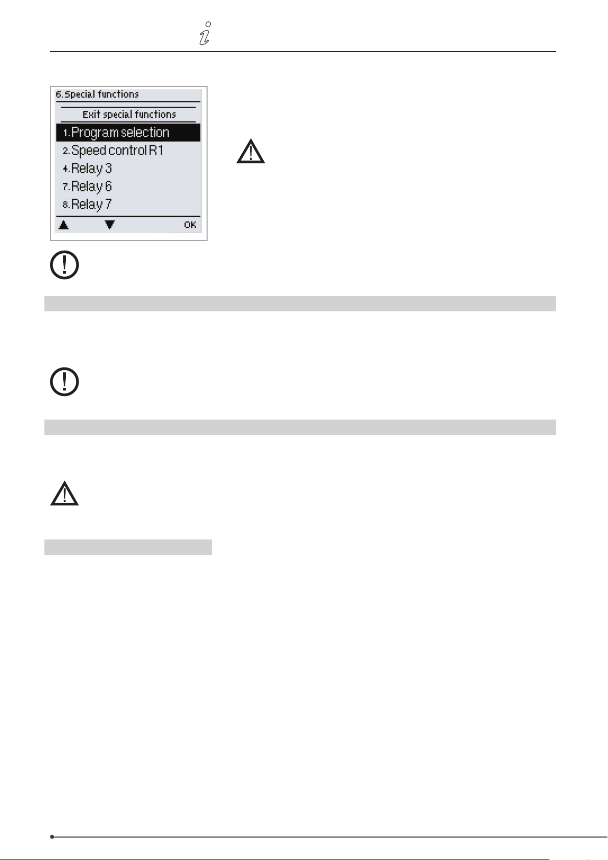
50 • Menu sequence and structure
6. Special functions
The menu numbering varies depending on the hydraulic schema chosen (see ”6.1 Program selection”)
6.1 Program selection
3110086 EHC20 UK 110515
In the ”6. Special functions” menu, basic settings and advanced functions
can be congured.
With the exception of the time, the settings should only
be congured by specialists.
You can exit the menu by pressing ”esc” or selecting ”Exit special functions”.
You can select and set the appropriate hydraulic variant for your particular application here (
schemata / systems 24).
Setting range: 1-48 / default: 1
Under normal circumstances, the program is selected once only when the specialist is setting up the controller.
If an incorrect program is selected, this may lead to unexpected malfunctions.
see Hydraulic variants /
6.2 Rotational speed control
If rotational speed control is enabled, a special internal electronic system in the EHC allows you to alter the rotational
speed of pumps according to process requirements.
This function should only be enabled by a specialist. Depending on the pump and pump level used, the
minimum rotational speed should not be set too low because the pump or the system could otherwise be
damaged. The information provided by the relevant manufacturers must also be observed! In case of doubt, it
is better to set the min. rotational speed and pump level too high rather than too low.
6.2.1 Rotational speed modes
The following rotational speed modes are available:
O: There is no rotational speed control. The pump connected is switched on at full speed or switched o.
Mode 1: The controller switches to the set max. rotational speed after the purging period. If the temperature dierence
∆T between the reference sensors (collector and storage tank) is below the set switch-on temperature dierence ∆T R1,
the rotational speed will be reduced.
If the temperature dierence between the reference sensors is above the set switch-on temperature dierence ∆T R1,
the rotational speed will be increased. If the controller has adjusted the rotational speed of the pump down to the
lowest level and the ∆T between the reference sensors is ∆To, the pump is switched o.
Mode 2: The controller switches to the set min. rotational speed after the purging period. If the temperature dierence
∆T between the reference sensors (collector and storage tank) is above the set switch-on temperature dierence ∆T R1,
the rotational speed will be increased.
If the temperature dierence ∆T between the reference sensors is below the set switch-on temperature dierence ∆T
R1, the rotational speed will be reduced.
If the controller has adjusted the rotational speed of the pump down to the lowest level and the ∆T between the
reference sensors is ∆To, the pump is switched o.
Page 51
3110086 EHC20 UK 110515
Mode 3: The controller switches to the set min. rotational speed after the purging period. If the temperature at the
reference sensor (collector; in systems with heat exchanger for relay 2 the heat exchanger) is above the setpoint value
to be set subsequently, the rotational speed will be increased.
If the temperature at the reference sensor is below the setpoint value to be set subsequently, the rotational speed will
be reduced.
Mode 4 (2 storage tank system)
If the valve is set towards the higher-ranking storage tank, the rotational speed will be regulated as in M3. If the valve is
set towards the lower-ranking storage tank, the rotational speed will be regulated as in M2.
Setting range: M1, M2, M3, M4, o / default: o
Menu sequence and structure • 51
6.2.2 Pump type
The type of speed-controlled pump should be set here.
Standard: Rotational speed control via wave packet control for standard pumps.
0-10 V: Control system for special pumps (e.g. high-eciency pumps) using a 0-10 V signal.
PWM: Control system for special pumps (e.g. high-eciency pumps) using a PWM signal.
6.2.3 Pump settings
In this menu, you can congure the settings for the 0-10 V or PWM pump.
If you select this menu, you may be prompted to save the rotational speed settings.
6.2.3.1 Pump
In this menu, you can select preset proles for the pump or congure all settings yourself under ”Manual”. The settings
can also be changed after selecting a prole.
6.2.3.2 Signal form
In this menu, you can set the type of pump: Heating pumps are designed to set maximum power with a small input
signal, while solar pumps provide low power from a small input signal. Solar = normal, heating = inverted.
Setting range: Normal, inverted / default: Normal
6.2.3.3 PWM o
This signal is output when the pump is switched o (pumps with cable breakage detection require a minimal signal).
Setting range: (Solar:) 0 to 50% / default: 0% - (Heating:) 50% to 100% / default: 100%
6.2.3.4 PWM on
The pump needs this signal in order to switch on and run at minimum speed.
Setting range: (Solar:) 0 to 50% / default: 10% - (Heating:) 50% to 100% / default: 90%
6.2.3.5 PWM max
With this value, you can specify the maximum frequency for the highest speed of an energy-saving pump which will be
used during purging or manual operation for example.
Setting range: (Solar:) 50 to 100% / default: 100% - (Heating:) 0% to 50% / default: 0%
6.2.3.6 0-10V o
This voltage is output when the pump is switched o (pumps with cable breakage detection require a minimum voltage).
Setting range: (Solar:) 0.0 to 5.0 V / default: 1.0 V - (Heating:) 5.0 to 0.0 V / default: 4.0 V
Page 52
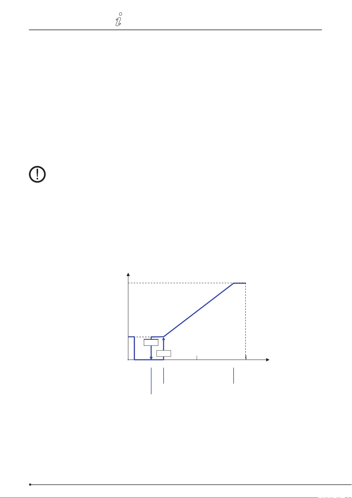
52 • Menu sequence and structure
Max rpm
Rotational speed
5-20% Stop
0-5% Cable Breakage detection
25% Start
25-90% Limits of regulation
Min rpm
PWM-Signal (%)
0 20% 25% 50% 100%
Stop
5%
PWM out 5% - 20%
PWM in >=25% PWM max <=90%
90%
3110086 EHC20 UK 110515
6.2.3.7 0-10V on
The pump needs this voltage in order to switch on.
Setting range: (Solar:) 0.0 to 5.0 V / default: 1.0 V - (Heating:) 5.0 to 10.0 V / default: 9.0 V
6.2.3.8 0-10V max
With this value, you can specify the maximum voltage level for the highest speed of an energy-saving pump which will
be used during purging or manual operation for example.
Setting range: (Solar:) 5.0 to 10.0 V / default: 10.0 V - (Heating:) 0.0 to 5.0 V / default: 0.0 V
6.2.3.9 Rotational speed when ”On”
In this menu, you can change the basis for calculating the rotational speed shown. If, for example, 30% is specied
here, 30% rotational speed will be shown when applying the frequency/voltage under ”PWM On” / ”0-10 V On”. If the
frequency/voltage for ”PWM Max” / ”0-10 V Max” is applied, 100% rotational speed will be shown. Intermediate values
will be calculated accordingly.
Setting range: 10 to 90% / default: 30%
This function does not inuence control functions. It merely inuences the display on the
status screen.
6.2.3.10 Show signal
Shows the pump signal set in a graphical and text overview.
6.2.3a Example pump settings
Page 53
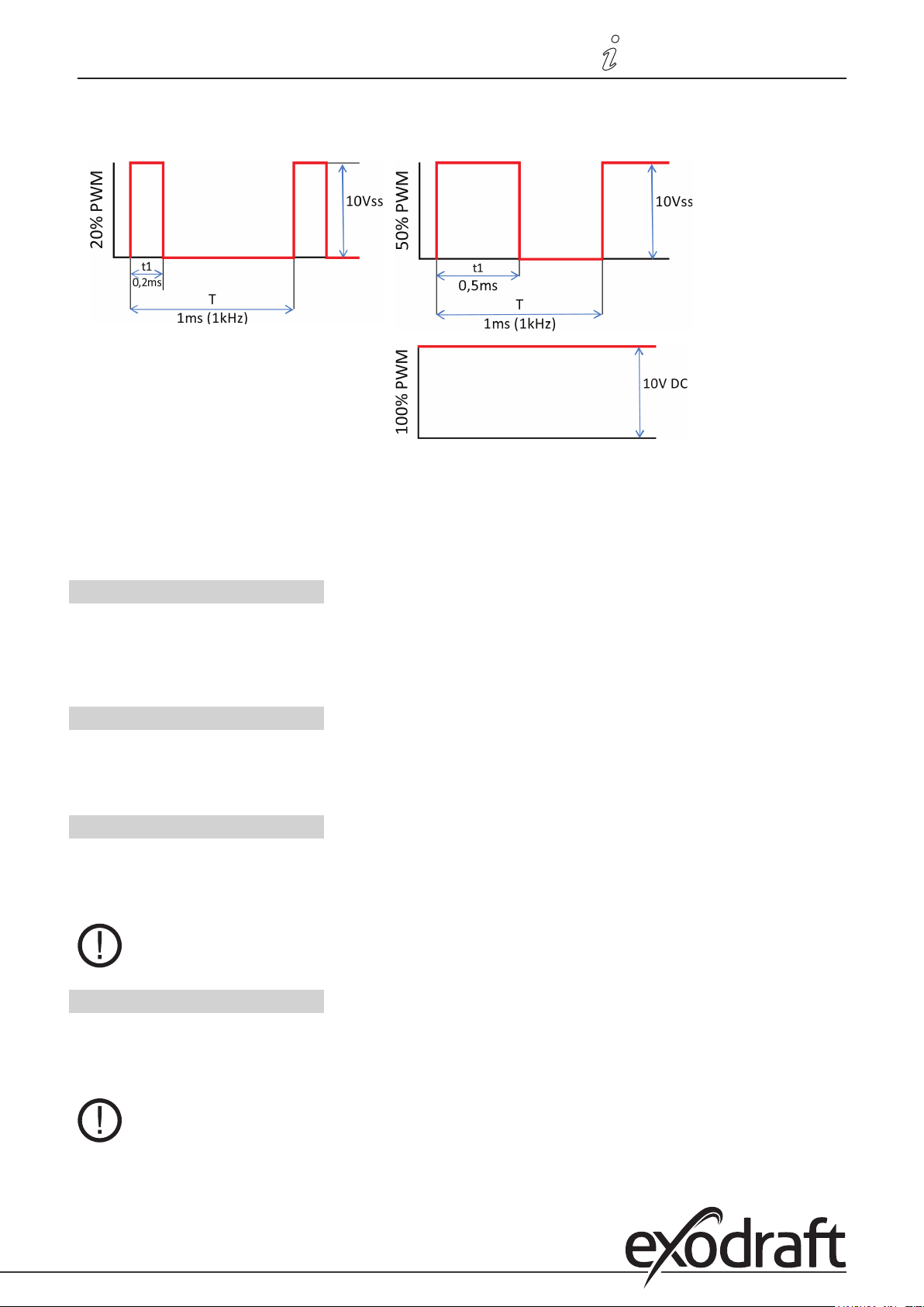
3110086 EHC20 UK 110515
6.2.3b Technical data – PWM and 0-10 V
PWM technical data:
PWM: 20% to 100%, 1 kHz
Designed for a 10 k ohm load
resistance
Menu sequence and structure • 53
0-10 V technical data:
0-10 V: 2 V to 10 V (20% to 100%)
Designed for a 10 k ohm load resistance.
10 V = 100% rotational speed
5 V = 50% rotational speed
2 V = 20% rotational speed
0 V = O
6.2.4 Purging time
During this time, the pump runs at full speed (100%) in order to ensure a reliable start-up. Only after this purging time
will the pump run at a controlled speed and switch to the max. or min. speed depending on the mode set.
The purging time cannot be used with 0-10 V / PWM pumps.
Setting range: 5 to 600 seconds / default: 8 seconds
6.2.5 Control time
The control time is used to determine the latency of rotational speed control in order to minimise temperature
uctuations. The time span required for a complete control cycle from minimum to maximum speed is specied here.
Setting range: 1 to 15 minutes / default: 4 minutes
6.2.6 Max. rotational speed
The maximum rotational speed of the pump is specied here. During the setting procedure, the pump runs at the
relevant speed and the throughow can be determined.
Setting range: 70% to 100% / default: 100%
If you select this menu, you may be prompted to save the rotational speed settings.
6.2.7 Min. rotational speed
The minimum rotational speed of the pump is specied here. During the setting procedure, the pump runs at the
relevant speed and the throughow can be determined.
Setting range: (”6.2.3.9 Rotational speed when ”On”, page 52) to max. rotational speed -5% / default: 30%
The percentages are guide values that may vary to a greater or lesser extent depending on the
system, pump and pumping level. 100% is the maximum possible controller voltage/frequency.
Page 54
54 • Menu sequence and structure
3110086 EHC20 UK 110515
6.2.8 Setpoint value
This value is the control setpoint value for Mode 3 (see ”6.2.1 Rotational speed modes”, page 50). If this value at the
sensor drops below, the rotational speed will be reduced. If it is exceeded, the rotational speed will be increased.
Setting range: 0°C to 90°C / default: 60°C
6.3 R2 rotational speed control
R2 rotational speed control - see ”6.2 Rotational speed control”, page 50
6.4 Relay functions
Free relays, i.e. relays not used in the basic schema, can be assigned the additional functions explained here. Each
additional function can be used only once.
R1 and R2: ELRs / electronically speed-controlled relays
R3 to R6: Mechanical relays 230 V
R7: Potential-free relay
V1 and V2: PWM and 0-10 V outputs
Please note the technical information for the relays (see page 19).
The symbols shown will be displayed on the overview screen as soon as you enable the function.
The numbering in this list does not correspond to the numbering in the controller menu.
6.4.1 Thermostat
Using the thermostat function, you can provide the system with additional energy on a time and temperature-controlled basis.
Setting range: On, O
Excessively high temperature settings can result in scalding or damage to the system.
The customer must make provisions to prevent scalding.
In economy mode, other values, e.g. T eco may apply.
6.4.1.1 TH setpoint
The target temperature at thermostat sensor 1. Below this temperature, the heating will switch on until
TH setpoint+hysteresis is reached.
Setting range: -20 - 99°C / default: 50°C
6.4.1.2 TH hysteresis
Hysteresis of the setpoint value.
Setting range: 1 - 50°C / default: 10°C
6.4.1.3 Thermostat sensor 1
Tsetpoint is measured at thermostat sensor 1
If thermostat sensor 2 is connected, the relay will switch on when the temperature drops below ”TH setpoint” at
thermostat sensor 1, and o when ”TH setpoint” + hysteresis at thermostat sensor 2 is exceeded.
Setting range: S1-S8, VFS1-2, Active storage tank / default: none
Page 55
3110086 EHC20 UK 110515
Menu sequence and structure • 55
6.4.1.4 Thermostat sensor 2
Optional switch-o sensor
If ”TH setpoint” + hysteresis at thermostat sensor 2 is exceeded, the relay will be switched o.
Setting range: S1-S8, VFS1-2, Active storage tank / default: none
6.4.1.5 T eco
Setpoint value in economy mode
When in economy mode: During solar charging, the ”T eco” value will be used instead of ”TH setpoint” as the setpoint
value. As soon as the temperature at thermostat sensor 1 drops below ”T eco”, the relay will be switched on and will
heat until ”T eco” + hysteresis is reached.
Setting range: 0 - 99°C / default: 40°C
6.4.1.6 Storage tank
Economy mode
Charging the storage tank selected here will enable the economy mode.
If this storage tank is currently being run using solar, the heating will only be switched on if the temperature is below ”T eco”.
Setting range: (Storage tank sensor) / default: First storage tank
6.4.1.7 Economy mode
In economy mode, the heating will only switch on when the temperature drops below the ”T eco”-setting, and will heat
to ”T eco” + hysteresis if solar charging is enabled.
Setting range: On, O / default: O
6.4.1.8 Times
Enable time for the thermostat function
You can set the desired time periods during which the thermostat function is enabled from a time point of view here.
You can enter three times for each day of the week. You can also copy individual days to other days. The thermostat
function is switched o outside the set times.
Setting range: 00:00 to 23:59 / default: 06:00 to 22:00
6.4.2 Thermostat 2
See ”6.4.1 Thermostat”, page 54
6.4.3 Cooling
With this function, an attempt is made to cool storage tanks for example to a variable setpoint temperature by releasing heat.
Setting range: On, O
6.4.3.1 Co Tsetpoint
The target temperature at thermostat sensor 1. Above this temperature, cooling will be switched on until Co Tsetpoint
+ hysteresis is reached.
Setting range: 0 - 99°C / default: 50°C
6.4.3.2 Co hysteresis
If the temperature at the cooling sensor undershoots Tsetpoint + hysteresis, the relay will be switched o.
Setting range: -50°C to -1°C / default: -10°C
Page 56
56 • Menu sequence and structure
3110086 EHC20 UK 110515
6.4.3.3 Cooling sensor
The reference sensor for the cooling function.
Setting range: S1-S8, VFS1-2, Active storage tank, RC / default: none
6.4.3.4 Times
Enable time for the cooling function
You can set the desired time periods during which the cooling function is enabled from a time point of view here. You
can enter three times for each day of the week. You can also copy individual days to other days. The cooling function is
switched o outside the set times.
Setting range: 00:00 to 23:59 / default: 06:00 to 22:00
6.4.4 Return ow temperature rise
With this function, the return ow temperature of a heating circuit can be increased with the help of the storage tank.
Setting range: On, O
6.4.4.1 RF Tmax
Maximum temperature at the storage tank sensor. If this temperature at the set storage tank sensor is exceeded,
the relay will be switched o again.
Setting range: 0 - 99°C / default: 70°C
6.4.4.2 ∆T return ow
Switch-on temperature dierence
If the temperature dierence between the storage tank sensor and the return ow sensor is exceeded, the relay will be
switched on.
Setting range: 5-20 K / default: 8 K
Switch-o temperature dierence:
If the temperature dierence between the storage tank sensor and the return ow sensor is exceeded, the relay will be
switched o.
Setting range: 2-19 K (limited by ∆T storage tank RF On) / default: 4 K
6.4.4.3 Return ow sensor
Return ow sensor selection
Setting range: S1-S8, VFS1-2, Active storage tank / default: none
6.4.4.4 Storage tank sensor
Storage tank sensor selection
Setting range: S1-S8, VFS1-2, Active storage tank / default: none
6.4.5 Anti-Legionella function
With the help of the anti-Legionella function, you can heat up the system at selected times in order to eliminate
Legionella bacteria.
Setting range: On, O
6.4.5.1 AL Tsetpoint
This temperature must be reached at the AL sensor(s) for the AL action time in order to allow successful heating.
Setting range: 60 - 99°C / default: 70°C
Page 57
3110086 EHC20 UK 110515
Menu sequence and structure • 57
6.4.5.2 AL action time
The AL Tsetpoint temperature at the AL sensors must prevail for this period of time in order to allow successful heating.
Setting range: 1-120 min / default: 15 min
6.4.5.3 Last AL heating
Details of when the last successful heating took place are shown here.
No setting options
6.4.5.4 AL sensor 1
The temperature for the AL function is measured by this sensor.
Setting range: S1-S8, VFS1-2, Active storage tank / default: none
6.4.5.5 AL sensor 2
Optional AL sensor
If this sensor is connected, Tsetpoint AL must be reached at both sensors for the action time in order to allow
successfulheating.
Setting range: S1-S8, VFS1-2, Active storage tank / default: none
6.4.5.6 AL times
AL heating will take place at these times.
Setting range: 00:00 to 23:59 / default: 06:00 to 22:00
This anti-Legionella function does not oer complete protection against Legionella because
the controller relies on a sucient supply of energy and the temperatures cannot be monitored
in the entire storage tank area and the connected pipe system. To ensure complete protection
against Legionella, your energy sources must be able to heat the water to the necessary
temperature, while your external control devices must ensure that the water is able to circulate
within the storage tank and pipe system.
The anti-Legionella function is switched o as standard.
When the anti-Legionella function is enabled, the storage tank will be heated to above the
“Tmax S2” value set, which can result in scalding and damage to the system.
6.4.6 Transfer
With this function, energy can be transferred from one storage tank to another.
Setting range: S1-S8, VFS1-2, Active storage tank / default: none
Page 58
58 • Menu sequence and structure
3110086 EHC20 UK 110515
6.4.6.1 ∆ T transfer
Temperature dierence for energy transfer.
If the temperature dierence between the sensors reaches ∆ T transfer on, the relay will be switched on. As soon as the
dierence drops to ∆ T transfer o, the relay will be switched o again.
On: Setting range: 5-20°C/ default: 8°C
O: Setting range: 2°C to ∆T on / default: 4°C
6.4.6.2 Tr Tmax
Setpoint temperature of the destination storage tank
If this temperature is measured at the sensor in the destination storage tank, the transfer function will be switched o.
Setting range: 0-90°C / default: 60°C
6.4.6.3 Tr Tmin
Minimum temperature in the source storage tank to allow transfer
Setting range: 0-90°C / default: 30°C
6.4.6.4 Source sensor
In this menu, you can set the sensor that is positioned in the storage tank from which energy is withdrawn.
Setting range: S1-S8, VFS1-2, Active storage tank / default: none
6.4.6.5 Destination sensor
In this menu, you can set the sensor that is positioned in the storage tank to which energy is transferred.
Setting range: S1-S8, VFS1-2, Active storage tank / default: none
6.4.7 Dierence
The relay is activated as soon as the set temperature dierence between the source and destination sensor prevails.
Setting range: On, O
6.4.7.1 ∆ T dierence
Switch-on dierence
The relay will switch on when this temperature dierence is reached.
Setting range: 3-50°C / default: 10°C
Switch-o dierence
The relay will switch o when this temperature dierence is reached.
Setting range: 2-49°C / default: 4 (the upper limit of the setting range is governed by the switch-on dierence)
6.4.7.2 Source sensor
Heat source sensor/heat supplier for dierential function
Sets the heat source sensor.
Setting range: S1-S8, VFS1-2, Active storage tank / default: none
6.4.7.3 Di Tmin
Minimum temperature at the source sensor to activate the dierential relay
If the temperature at the source sensor is below this value, the dierence function will not be switched on.
Setting range: 0 to 90°C / default: 20°C
6.4.7.4 Destination sensor
Heat sink sensor/heat outlet for the dierential function
Sets the heat outlet sensor.
Setting range: S1-S8, VFS1-2, Active storage tank / default: none
Page 59
3110086 EHC20 UK 110515
Menu sequence and structure • 59
6.4.7.5 Di Tmax
Maximum temperature at the destination sensor to activate the dierential relay
If the temperature at the destination sensor is above this value, the dierence function will not be switched on.
Setting range: 0 to 99°C / default: 60°C
6.4.8 Solid fuel boiler
The relay will be used to control an additional solid fuel boiler.
Setting range: On, O
6.4.8.1 SF Tmin
Minimum temperature in the boiler for switching on the pump. If the temperature at the boiler sensor is below this
temperature, the relay will not be switched on.
Setting range: 0°C to 99°C / default: 70°C
6.4.8.2 SF Tmax
Maximum temperature in the storage tank. If this is exceeded, the relay will be switched o.
Setting range: O up to 100°C / default: 70°C
6.4.8.3 ∆ T SF
The temperature dierence between the boiler and storage tank as a switch-on and switch-o condition.
Switch-on temperature dierence ∆ T SF
Setting range: 5 to 20 K / default: 8
Switch-o temperature dierence ∆ T SF
Setting range: 0°C up to switch-on ∆ T SF / default: 4
6.4.8.4 Boiler sensor
The sensor that is used as a boiler sensor.
Setting range: S1-S8, VFS1-2, Active storage tank / default: none
6.4.8.5 Storage tank sensor
The sensor that is used as a storage tank sensor.
Setting range: S1-S8, VFS1-2, Active storage tank / default: none
6.4.9 Error messages
The relay will be switched on if one or more of the set conditions become active.
This function can also be inverted so that the relay is switched on all the time (Permanently on) and then switched o
when a protective function becomes active.
Setting range: On, Inverted, O / default: O
Collector alarm
Collector protection
System protection
Frost protection
Return cooling
Anti-Legionella function
Reports
Page 60
60 • Menu sequence and structure
3110086 EHC20 UK 110515
6.4.10 Pressure control
The relay switches on if the pressure drops below a minimum or exceeds a maximum.
Setting range: On, O / default: O
6.4.10.1 Pressure control
In this menu, you can enable system pressure control via a direct sensor. As soon as the set pressure conditions are
exceeded, the set relay will switch on.
6.4.10.2 RPS1 / RPS2
Pressure sensor model
In this menu, you can set the type of pressure sensor used.
Please note: If, for example, VFS1 is connected, RPS1 will be hidden.
Setting range: O; 0-0.6 bar; 0-1 bar; 0-1.6 bar; 0-2.5 bar; 0-4 bar; 0-6 bar; 0-10 bar
Default: O
6.4.10.3 Pmin
Minimum pressure in the system. If this pressure drops below, the controller will issue an error message and the relay
will switch (hysteresis: 0.5 bar).
Setting range: O; 0.0 to 10 bar
Default: O
6.4.10.4 Pmax
Maximum pressure in the system. If this pressure is exceeded, the controller will issue an error message and the relay
will switch (hysteresis: 0.5 bar).
Setting range: O; 0.0 to 10 bar
Default: O
6.4.11 Booster pump
An additional pump which lls the system at the start of each solar charge.
6.4.11.1 Filling time
Duration of pump operation
Determines for how long the pump should ll the system after being triggered.
Setting range: 0 - 120 seconds / default: 30 seconds
6.4.12 Parallel operation R (X)
The relay operates at the same time as the set relay R1 or R2.
Setting range: On, O
6.4.12.1 Delay
In this menu, you can specify how long after starting R1 or R2 the system waits until the relay operating in parallel starts.
Setting range: 0 - 120 seconds / default: 30 seconds
Page 61
3110086 EHC20 UK 110515
Menu sequence and structure • 61
6.4.12.2 Follow-up time
In this menu, you can specify how long the relay operating in parallel continues to run after R1 or R2 switches o.
Setting range: 0 - 120 seconds / default: 30 seconds
6.4.13 Parallel operation R2
See ”6.4.12 Parallel operation R (X)”, page 60
6.4.14 Permanently on
The relay is always switched on.
6.4.15 Heating circuit
A heating circuit pump is controlled with xed hysteresis (+/-1°C) so as to reach the setpoint value.
A 30-second switch-on and switch-o delay is set as standard in order to prevent cycling.
RC21 Room Controller can be used as a room sensor.
Setting range: On, O
6.4.15.1 Room setpoint day
Room setpoint temperature during daytime operation. If this temperature at the room sensor is exceeded within the
set times, the relay will switch o.
Setting range: 10 to 30°C / default: 20°C
6.4.15.2 Room setpoint night
Room setpoint temperature during night-time operation. If this temperature at the room sensor is exceeded outside
the set times, the relay will switch o.
Setting range: 10 to 30°C / default: 16°C
6.4.15.3 Room sensor
Allows you to select the reference sensor for the room temperature.
Setting range: S1-S8, VFS1-2, Active storage tank / default: none
6.4.15.4 Times
Daytime operating times for the heating circuit function
You can set the desired time periods during which the heating circuit operates in daytime mode here. You can enter
three times for each day of the week. You can also copy individual days to other days. The heating circuit operates in
night-time mode outside the set times.
Setting range: 00:00 to 23:59 / default: 06:00 to 22:00
Page 62
62 • Menu sequence and structure
3110086 EHC20 UK 110515
6.5 Heat quantity
1. Constant throughow
If ”constant throughow” is enabled for heat quantity metering purposes, the approximate heat yield will be calculated
using the values for antifreeze, antifreeze concentration and system throughow (values to be entered manually) as
well as the collector and storage tank sensor values measured.
Additional information regarding the antifreeze, the antifreeze concentration and the system throughow is required.
A correction factor for heat quantity calculation can also be set using the Oset ∆T value. Because the heat quantity
calculation is based on the collector temperature and storage tank temperature, system-related deviations in the
displayed collector temperature compared to the actual forward ow temperature or in the displayed storage tank
temperature compared to the actual return ow temperature can occur. These deviations can be corrected using the
Oset ∆T value. Example: Displayed collector temperature 40°C, read forward ow temperature 39°C, displayed storage
tank temperature 30°C, read return ow temperature 31°C means a setting of -20% (displayed ∆T 10 K, actual ∆T 8 K =>
-20% correction value).
The heat quantity data in the “constant throughow” mode are merely guide values
calculated in order to check the system functions.
6.5.1 Forward ow sensor (X)
In this menu, you can specify which sensor is used to measure the forward ow temperature.
Setting range: S1-S8, VFS1-2, Active collector, Active storage tank / default: S8
6.5.2 Return ow sensor
In this menu, you can specify which sensor is used to measure the return ow temperature.
Setting range: S1-S8, VFS1-2, Active collector, Active storage tank / default: S1
6.5.3 Glycol type
In this menu, you can specify the type of antifreeze used. If no antifreeze is used, please set the proportion of glycol to 0.
Setting range: Ethylene, propylene / default: Ethylene
6.5.4 Proportion of glycol
The proportion of antifreeze added to the medium in percent.
Setting range: 0-100% / default: 45%
6.5.5 Forward throughow (X)
Nominal system throughow
The system throughow in litres per minute which is used as a basis for calculating the metered heat quantity.
Setting range: 0 - 100 l/min / default: 5 l/min
6.5.6 Oset ∆T
Temperature dierence correction factor for heat metering
Because the heat quantity calculation is based on the collector temperature and storage tank temperature, systemrelated deviations in the displayed collector temperature compared to the actual forward ow temperature or in the
displayed storage tank temperature compared to the actual return ow temperature can occur. These deviations can
be corrected using the Oset ∆T value. Example: Displayed collector temperature 40°C, read forward ow temperature
39°C, displayed storage tank temperature 30°C, read return ow temperature 31°C means a setting of -20% (displayed
∆T 10 K, actual ∆T 8 K => -20% correction value).
Setting range: -50 to +50% / default: 0%
6.5.7 VFS (X)
In this menu, you can specify the type of direct sensor used.
Setting range: O; 1-12; 1-20; 2-40; 5-100; 10-200; 20-400 / default: O
Page 63
3110086 EHC20 UK 110515
Menu sequence and structure • 63
6.5.8 VFS position
In this menu, you can specify whether the direct sensor is mounted in the forward ow or the return ow.
Setting range: Forward ow, return ow / default: Return ow
To avoid damaging the vortex ow sensor, it is recommended that you position it only in the
return ow. If, contrary to this recommendation, you do position it in the forward ow, you
must observe the maximum permitted temperature! (0°C to 100°C during permanent operation
and -25°C to 120°C for short periods)
6.5.9 Reference sensor
You can specify the sensor to be used for heat metering here.
Setting range: S1-S8, VFS1-2, Active collector, Active storage tank / default: S1
6.6 Pressure monitoring
In this menu, you can enable system pressure monitoring via a direct sensor. As soon as the set pressure conditions are
exceeded, a message will be generated and the LED will ash red.
6.6.1 Pressure monitoring
If the pressure drops below a minimum or exceeds a maximum, a message will be displayed and the LED will ash red.
Setting range: On, O / default: O
6.6.1.1 RPS1 / RPS2
Pressure sensor model
In this menu, you can set the type of pressure sensor used.
Please note: If for example VFS1 is connected, RPS1 will be hidden.
Setting range: O; 0-0.6 bar; 0-1 bar; 0-1.6 bar; 0-2.5 bar; 0-4 bar; 0-6 bar; 0-10 bar
Default: O
6.6.1.2 Pmin
Minimum pressure in the system. If this pressure drops below, the controller will issue an error message and the red LED
will ash.
Setting range: O; 0.0 to 10 bar
Default: O
6.6.1.3 Pmax
Maximum pressure in the system. If this pressure is exceeded, the controller will issue an error message and the red LED
will ash.
Setting range: O; 0.0 to 10 bar
Default: O
6.7 Sensor calibration
Deviations in the displayed temperature values, e.g. as a result of long cables or sensors not being positioned optimally,
can be corrected manually here. The settings are congured individually for each sensor in steps of 0.8°C (temperature)
or 0.2% of the measurement range of the VFS / RPS sensor (throughow / pressure).
Sensor oset per setting range: -100 ... +100 / default: 0
Settings only need to be made by a specialist in special cases during the setup. Incorrect
measurements can result in malfunctions.
Page 64
64 • Menu sequence and structure
3110086 EHC20 UK 110515
6.8 Setup
Once launched, the setup wizard guides you through the basic settings for the setup in the correct order and provides
brief descriptions of the various parameters in the display.
Pressing the ”esc” button takes you back to the previous value so that you can view the selected setting again and
adjust it if necessary. Pressing the ”esc” button more than once takes you back to the selection mode, thus cancelling
the setup wizard. (See also ”F.2 Setup wizard”, page 44)
The setup wizard should only be launched by a specialist! Observe the explanations of the
individual parameters in this manual, and check whether further settings are necessary for
your application.
6.9 Factory settings
All settings can be reset to the original factory settings.
All controller parameters and statistics etc. will be irretrievably lost. The controller will then
need to be set up again.
6.10 SD card
Settings for the logging function with data storage on the SD card.
6.10.1 Logging
In this menu, you can enable the logging of sensor and relay data and adjust the settings. Various le formats are available.
Setting range: On, O / default: O
6.10.2 Free storage space
Shows the amount of free space available on the SD card.
6.10.3 Load conguration
This function allows you to load all controller settings from the SD card.
All previous controller settings will be overwritten.
6.10.4 Save conguration
This function allows you to save all controller settings including the service values on the SD card.
6.10.5 Firmware update
With this function, the rmware stored on the SD card will be transferred to the controller.
During the rmware update, do not switch o the controller or disconnect the power as this
can cause irreparable damage.
Settings can be changed and/or overwritten. After the rmware update, reset the controller to
the factory settings and carry out the setup procedure again.
6.10.6 Eject
In order to remove the SD card with no risk of damage or data loss, you should deregister it here rst.
Page 65
3110086 EHC20 UK 110515
Menu sequence and structure • 65
6.11 Time and date
In this menu, you can set the current time and date.
In order to evaluate system data, the controller clock must be set correctly. Please note that
the clock does not continue running in the event of a power failure and will therefore need to
be set again.
6.12 Summer time
If this function is enabled, the controller will automatically switch to winter time or summer time
(DST – daylight saving time).
6.13 Power saving mode
In power saving mode, the background lighting for the display will be switched o if no button is pressed for two minutes.
Default: O
If a message has been issued, the background lighting will not switch o until the message
has been viewed by the user.
6.14 Ethernet
In this menu, you can adjust the settings for the controller’s Ethernet module.
6.14.1 Ethernet
Enables or disables the Ethernet function.
Setting range: On, O / default: O
6.14.2 MAC address
Displays the controller’s individual MAC address.
No setting options
6.14.3 TCP/IP address
In this menu, you can set the controller’s IPV4 TCP/IP address.
6.14.4 Network mask
In this menu, you can set the network’s network mask.
6.14.5 Gateway
In this menu, you can set the IP of the standard gateway for the controller.
6.14.6 Login
In this menu, you can dene users who are allowed to access the controller via the network.
Up to four users (User 01 to User 04) can be dened. Login names and passwords are set.
The following statuses can be set:
Disabled No access
Guest Information can be read from controller but no changes can be made
Administrator Information can be read from controller and it can be fully remote-controlled
6.15 Temperature unit
In this menu, you can specify which temperature unit is displayed.
Setting range: °F or °C / default: °C
Page 66
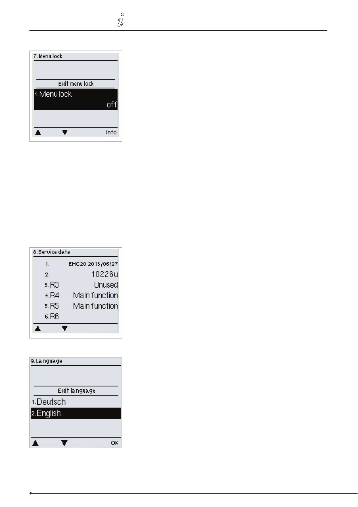
66 • Menu sequence and structure
3110086 EHC20 UK 110515
7. Menu lock
In the ”7. Menu lock” menu, you can prevent the controller settings being
accidentally changed.
You can exit the menu by pressing ”esc”.
The following menus remain fully accessible even if the menu lock is enabled and changes can be made if necessary:
1. Measurements
2. Statistics
6.23. Time and date
8. Menu lock
9. Service values
To lock the other menus, select ”Menu lock on”.
To unlock the menus again, select ”Menu lock o”.
Setting range: on, o / default: o
8. Service Data
The ”8. - Service Data” menu can be used by a specialist or the manufacturer
for remote-diagnostics etc. in the event of an error.
You can exit the menu at any time by pressing ”esc”.
The service Data are saved on the SD card during logging.
9. Language
In the ”9. - Language” menu, you can select the language for the menus.
You will automatically be asked to select a language when the controller is
used for the rst time.
The languages available may vary depending on the device version! Not all
device versions oer a choice of languages!
Page 67
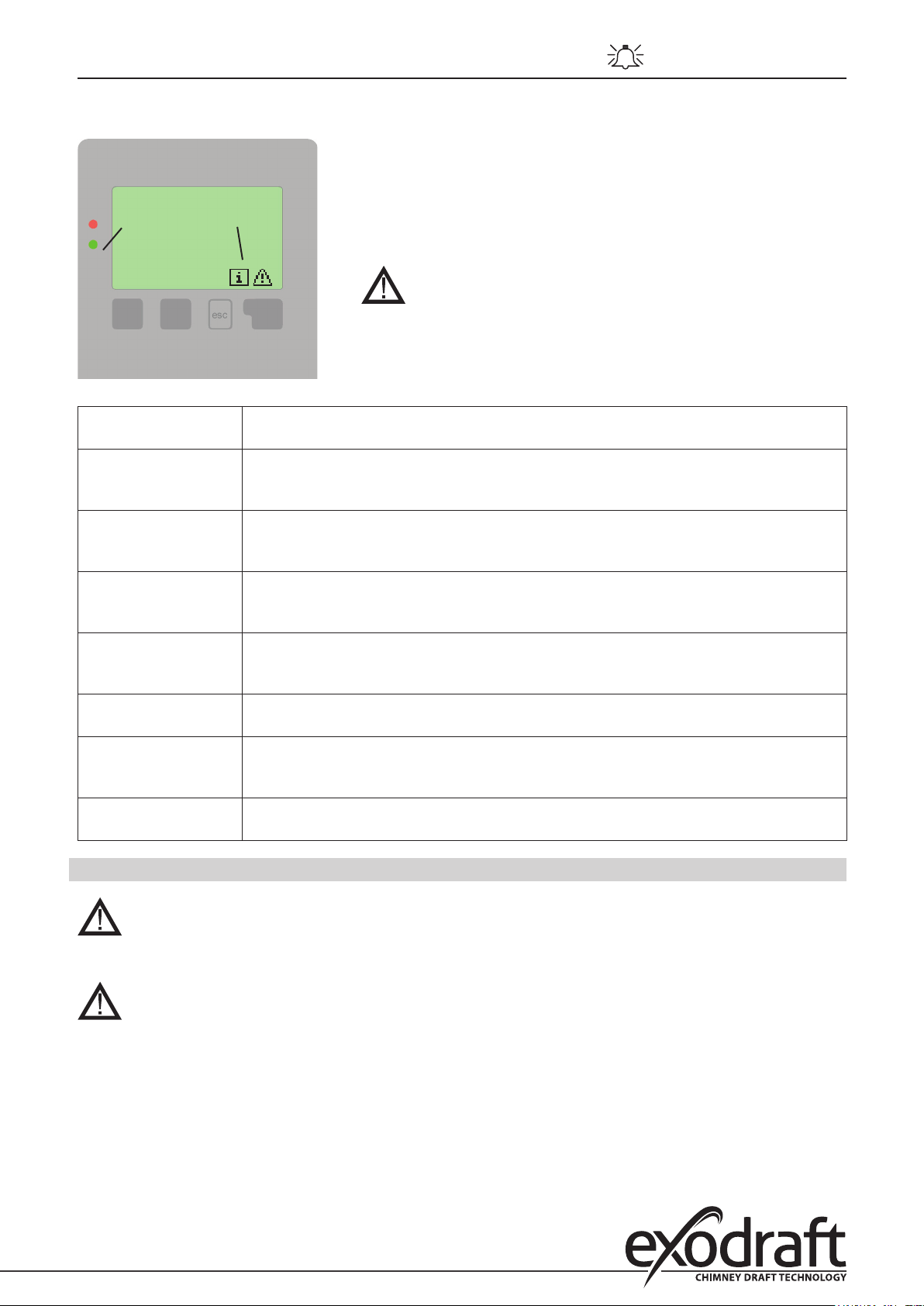
3110086 EHC20 UK 110515
Q. Faults with error messages
If the controller identies a malfunction, the warning symbol will appear in
the display. If the error is no longer present, the warning symbol will change
to an information symbol.
Pressing the button below the warning or information symbol will bring up
(Led ashes + warning symbol)
more detailed information regarding the error.
Faults with error messages • 67
Do not try to deal with problems yourself.
In the event of an error, please consult a specialist.
Possible error
messages:
Sensor fault Either the sensor, the sensor input on the controller or the connecting lead is/was defective.
Restart Indicates that the controller was restarted, e.g. owing to a power failure.
Time and date This message appears automatically after an extended power failure because the time and
Excessive cycling This message is shown if the solar pump switches on and o again more than ve times in
No throughow This message is shown if the solar pump is running and dT >=50°C over a ve-minute period.
Excessive/insucient
system pressure
SD card error This message is displayed if an SD card was recognised but the controller cannot write or
Information for specialists:
(See "Temperature resistance table for Pt1000 sensors", page 69)
Check date and time!
date will need to be checked and adjusted if necessary.
ve minutes (i.e. if 11 switching operations are recorded).
This message is displayed if the pressure monitoring function is enabled and Pmin or Pmax
is exceeded.
read data.
Q.1 Replace fuse
Repair and maintenance work should only be carried out by specialists. Before working on the
device, disconnect the power supply and ensure that the device cannot be switched on again.
Check that the power is switched o.
Use only the spare fuses supplied or an equivalent fuse with the following rating: T2 A / 250 V.
Three fuses are tted to the controller. These protect the various relays as well as the electronic control system. If the
controller is switched on but the functions and display are not working or the mechanical or electronic relays are not
functioning, open the device as described under C, remove the old fuse and check it.
Replace the defective fuse, identify any defective external components (e.g. pump) and replace them too.
Switch on the controller again and check that the switch outputs are functioning in manual mode as described under
”3.2 Manual”, page 48.
Page 68
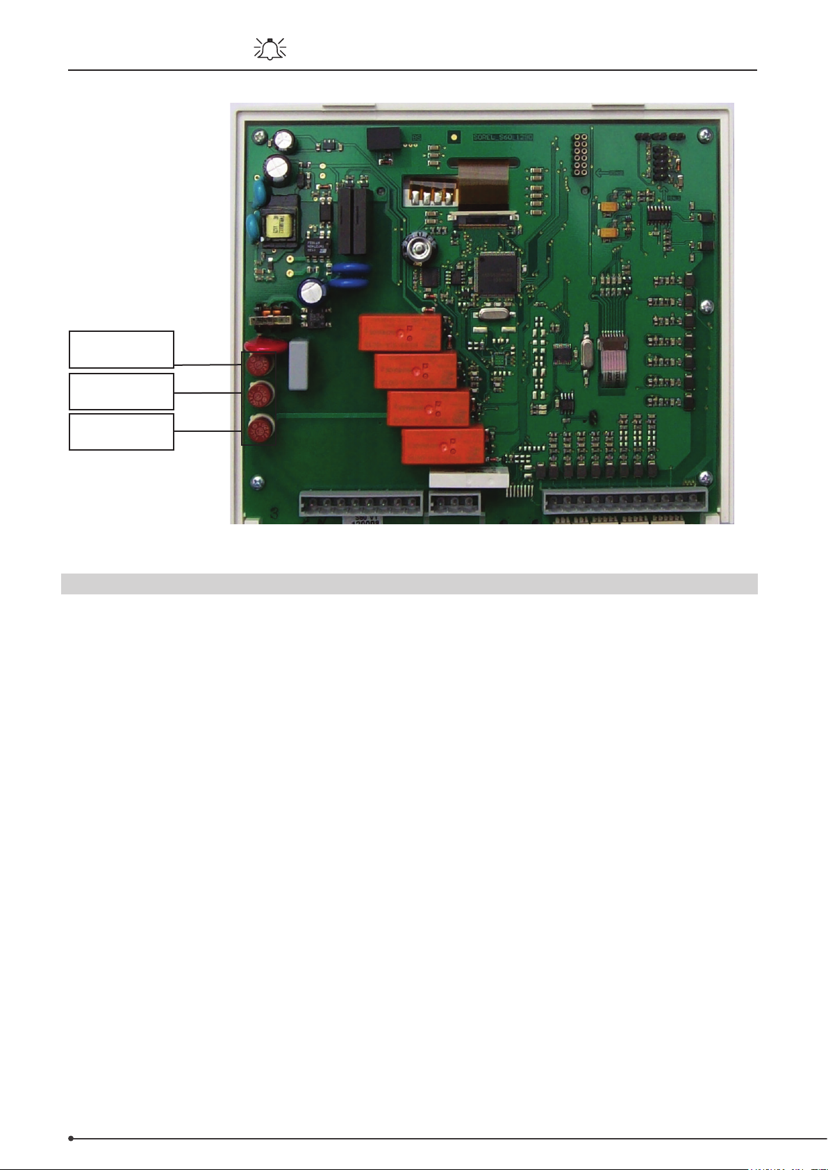
68 • Faults with error messages
Fuses
T2 A / 250 V
Circuit board
Electronic
relays
Mechanical
relays
3110086 EHC20 UK 110515
Q.2 Maintenance
As part of the general annual maintenance for your heating system, you should have the controller
functions checked by a specialist and have your settings optimised if necessary.
• Maintenance procedures:
• Checking the time and date (see “6.11 Time and date”, page 65)
• Assessing the statistics and carrying out a plausibility check (see “2. Statistics”, page 47 )
• Checking the error memory (see “2.4 Messages”, page 47)
• Assessing the current measurements and carrying out a plausibility check (see “1. Measurements”, page
46)
• Checking the switch outputs/loads in manual mode (see “3.2 Manual”, page 48)
• If necessary, optimizing the parameters set
Page 69
3110086 EHC20 UK 110515
Useful information / tips and tricks • 69
R. Useful information / tips and tricks
Temperature resistance table for Pt1000 sensors
°C 0 10 20 30 40 50 60 70 80 90 100
Ω 1000 1039 1077 1116 1155 1194 1232 1270 1308 1347 1385
Instead of setting the system throughow with a volume ow limiter, it is better to adjust the
throughow using the selector switch on the pump and the controller’s ”Max. rotational speed” setting
(see ”6.2.6 Max. rotational speed”, page 53). This saves electricity!
The service values (see ”8. Service data”, page 66) include not only current measurements and
operating statuses but also all controller settings. Following a successful setup, save the service values
on a one-o basis (”6.10.4 Save conguration”, page 64)!
In the event of queries regarding control functions or malfunctions, the service values provide a reliable
and successful remote-diagnostics method. Save the service values (see ”8. Service data”, page 66 and
”6.10.4 Save conguration”, page 64) when the malfunction occurs. Send the data along with a brief
description of the fault to a specialist or the manufacturer!
Log the statistics and data that are of particular importance to you (see ”2. Statistics”, page 47) at
regular intervals in order to prevent data loss.
Page 70
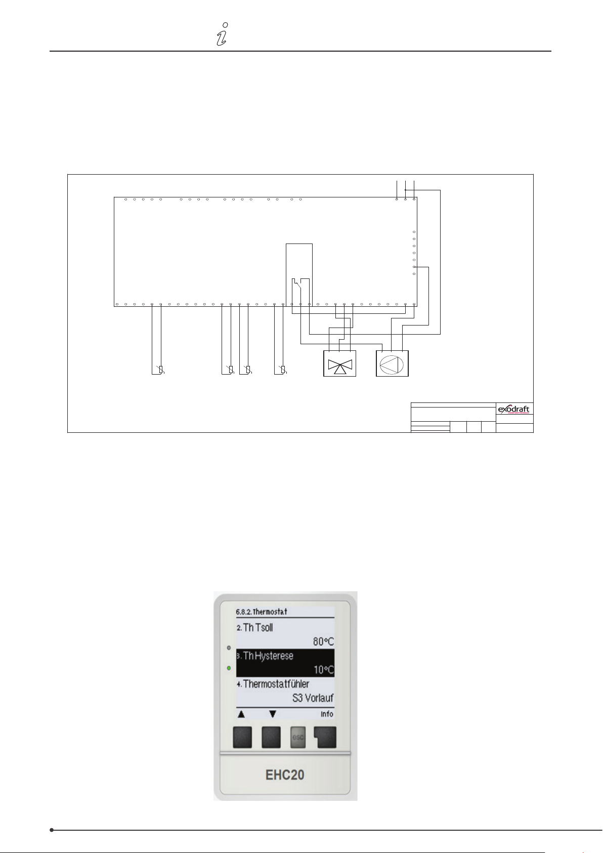
70 • Useful information / tips and tricks
Project:
Drawing Date:
Rev. Date:
Rev.:
Title:
Ref.:
Rauchgastemperatur
Vorlaufstemperatur
Pufferspeicher-
temperatur
Drawing N°:
3110082
Wärmetauchertemp. (Optional)
EHC20 System 6.1.3
TFI B
26-09-13
Temperaturfühlereingang 8
VFS2 Sensor
VFS1 Sensor
Netz / Mains
0-10V Ausgang
0-10V Ausgang
exodraft EHC10/EHC20 Regler
PF-Relais
Relaisausgang 6
Relaisausgang 1
RC stecker
CAN
CAN
Temperaturfühlereingang 7
Temperaturfühlereingang 6
Temperaturfühlereingang 5
Temperaturfühlereingang 4
Temperaturfühlereingang 3
Temperaturfühlereingang 2
Temperaturfühlereingang 1
Relaisausgang 5
Relaisausgang 4
Relaisausgang 3
Relaisausgang 2
Mischer Pumpe
1 111 12 2222 3 3 34 44 5
CGND GNDGND GNDGND GND GNDGNDGND GND
L
N NN
N
NNNNC NO
PE
PE
PE
PE
PE
PE
PE
PE
R1R2R3R4R5R6S1S2S3S4S5S6S7S8V1V2
1 111 12 2222 3 3 34 44 5
CGND GNDGND GNDGND GND GNDGNDGND GND
L
N NN
N
NNNNC NO
PE
PE
PE
PE
PE
PE
PE
PE
R1R2R3R4R5R6S1S2S3S4S5S6S7S8V1V2
CCWCW N
CCWCW N
L
N
PE
L
N
PE
U
-S1
U
-S3
U
-S8
L1
N
PE
U
-S4
3110086 EHC20 UK 110515
Solution by high temperature in the heat-exchanger and when the temperature S8 ist smaller than
the set-point.
The temperature in the heat-exchanger can become to high when the heat source stops and the
temperature S8 drops below the set-point. A solution for this is described below.
Connect the pump according to this diagram
• In the menu go to „ Special functions“
• Choose menu point „Relay 7“ o
• Choose menu sub-point „Thermostat“ o
• Press conrm and choose „ON“
• Set Th Tset on 80°C
• Change thermostat sensor to S3 ow
• Optional: Mount an S4 temperature sensor on the chassis of the heat-exchanger module and
change the thermostat sensor to S4.
Page 71
EU Declaration of Conformity • 71
Declaration of Conformity
DK: EU-Overensstemmelseserklæring
GB: Declaration of Conformity
DE: EU-Konformitätserklärung
FR: Déclaration de conformité de l’Union Européenne
NO: EU-Samsvarserklæring
-erklærer på eget ansvar, at følgende produkter:
-hereby declares that the following products:
-erklärt hierdurch auf eigene Verantwortung, daß folgende Produkte:
-déclare, sous sa propre responsabilité, que les produits suivants:
-erklærer på eget ansvar at følgende produkter:
-som er omfattet af denne erklæring, er i overensstemmelse med
følgende standarder:
-were manufactured in conformity with the provisions of the following
standards:
-die von dieser Erklärung umfaßt sind, den folgenden Normen:
-auxquels s’applique cette déclaration sont en conformité avec les
normes ci-contre:
-som er omfattet av denne erklæring, er i samsvar med følgende standarder:
EN 60335-1, EN60335-2-102, EN 61000-6-1, EN 61000-6-2, EN 61000-6-3, EN 301489-1, EN 301489-3, EN 300220-1, EN298:2003
-i.h.t bestemmelser i direktiv:
-in accordance with
-entsprechen gemäß den Bestimmungen der folgenden Richtlinien:
-suivant les dispositions prévues aux directives:
-i.h.t bestemmelser i direktiv:
-Lavspændingsdirektiv:
-the Low Voltage Directive:
-Niederspannungsrichtlinie:
-Directive Basse Tension:
-Lavspenningsdirektivet:
-EMC-direktivet:
-and the EMC Directive:
-EMV-Richtlinie:
-Directive Compatibilité Electromagnétique:
-EMC-direktivet:
-Gas Appliances Directive (GAD)
Odense, 05.08.2013
-Adm. direktør
-Managing Director
Jørgen Andersen
NL: EU-Conformiteits verklaring
SE: EU-Överensstämmelsedeklaration
FI: EU-Vaatimustenmukaisuusvakuutus
IS: ESS-Samræmisstaðfesting
IT: Dichiarazione di Conformità Unione Europea
exodraft a/s
C.F. Tietgens Boulevard 41
DK-5220 Odense SØ
-veklaart dat onderstaande producten:
-deklarerar på eget ansvar, att följande produkter:
-vastaa siltä, että seuraava tuote:
-Staðfesti à eigin àbyrgð, að eftirfarandi vörur:
-dichiara con la presente che i seguenti prodotti:
EHC /10 /20
-zijn vervaardigd in overeenstemming met de voorschriften uit de
hieronder genoemde normen en standaards:
-som omfattas av denna deklaration, överensstämmer m ota tämä
selvitys koskee, on seuraavien standardien mukainen:
-sem eru meðtalin i staðfestingu Pessari, eru i fullu samræmi við
eftirtalda staðla:
-sono stati fabbricati in conformità con le norme degli standard
seguenti:
-en voldoen aan de volgende richtlijnen:
-enligt bestämmelserna i följande direktiv:
-seuraavien direktiivien määräysten mukaan:
-med tilvisun til àkvarðana eftirlits:
-in conformità con le direttive:
-de laagspanningsrichtlijn:
-Lågspänningsdirektivet:
-Pienjännitedirektiivi:
-Smáspennueftirlitið:
-Direttiva Basso Voltaggio:
2006/95/EC
-en de EMC richtlijn:
-EMC-direktivet:
-EMC-direktiivi:
-EMC-eftirlitið:
-Direttiva Compatibilità Elettromagnetica:
2004/108/EC
2009/142/EC
-Algemeen directeur
-Geschäftsführender Direktor
-Président Directeur Général
-Verkställande direktör
-Toimitusjohtaja
-Framkvemdastjori
-Direttore Generale
Page 72

DK: exodraft a/s
C. F. Tietgens Boulevard 41
DK-5220 Odense SØ
Tel: +45 7010 2234
Fax: +45 7010 2235
[email protected]
www.exodraft.dk
NO: exodraft a/s
Storgaten 88
NO-3060 Svelvik
Tel: +47 3329 7062
Fax: +47 3378 4110
[email protected]
www.exodraft.no
DE: exodraft GmbH
Soonwaldstraße 6
DE-55569 Monzingen
Tel.: +49 (0)6751 855 599-0
Fax: +49 (0)6751 855 599-9
[email protected]
www.exodraft.de
SE: exodraft a/s
Årnäsvägen 25B
SE-432 96 Åskloster
Tlf: +46 (0)8-5000 1520
Fax: +46 (0)340-62 64 42
[email protected]
www.exodraft.se
UK: exodraft Ltd.
Unit 4B, Lancaster Ct.
Coronation Road
Cressex Business Park
GB-High Wycombe HP12 3TD
Tel: +44 (0)1494 465 166
Fax: +44 (0)1494 465 163
[email protected]
www.exodraft.co.uk
3110086 EHC20 UK 110515
 Loading...