

Exodraft EBC30 Installation And Operation Manual
EBC30 3002180 100315
EBC30
Installation and operation manual
READ AND SAVE THESE INSTRUCTIONS!
Product information Chapters 1 + 2
Mechanical installation Chapter 3
Electrical installation Chapter 4
Start up and conguration Chapter 5
Maintenance and troubleshooting Chapter 6
Job name: _________________________________
Installer: __________________________________
Installation date: ___________________________
USA
CAN
Distributor contact information:
ENERVEX Inc. • T: 800.255.2923
info@enervex.com • www.enervex.com

EBC30 3002180 100315
Contents
2
1. Product information
1.1 Function ........................................................................3
1.2 Shipping ........................................................................3
1.3 Warranty .........................................................................
1.3 Warranty ........................................................................4
1.4 EBC30 control components ......................................................4
2. Specications
2.1 Dimensions and capacities ......................................................5
3. Mechanical installation
3.1 Location ........................................................................6
3.2 Mounting of control ............................................................6
3.3 Mounting of transducer .........................................................7
3.4 Installation of stack probe (if applicable) .........................................7
3.5 Installation of outdoor pressure probe (if applicable) .............................8
4. Electrical installation
4.1 General .........................................................................9
4.2 Relay board connections .......................................................10
4.3 Triac board connections . . . . . . . . . . . . . . . . . . . . . . . . . . . . . . . . . . . . . . . . . . . . . . . . . . . . . . . . 10
4.4 Wiring of Ashcroft XTP sensor ...................................................11
4.5 Wiring of the control for priority operation ......................................11
5. Startup and conguration
5.1 Sequence of operation .........................................................12
5.2 Pre-operation inspection .......................................................13
5.3 Key panel identication and operation ..........................................13
5.4 Initiation of control .............................................................14
5.5 Basic control set-up ............................................................14
5.6 Detailed control programming .................................................16
5.7 Programming sequence ........................................................17
6. Maintenance and troubleshooting
6.1 EBC30 Factory settings .........................................................19
Symbol legend
The following terms are used throughout this manual to bring attention to the presence of potential hazards
or to important information concerning the product.
DANGER
Indicates an imminent hazardous situation which,
if not avoided, will result in death, serious injury or
substantial property damage.
TO REDUCE THE RISK OF FIRE, ELECTRICAL SHOCK OR INJURY TO PERSONS,
OBSERVE THE FOLLOWING:
1. Use this unit in the manner intended by the manufacturer. If
you have questions, contact the manufacturer’s distributor at the
address or telephone number listed on the front of the manual.
2. Before servicing or cleaning the unit, switch o at service panel
and lock service panel to prevent power from being switched on
accidentally.
3. Installation work and electrical wiring must be done by a qualied person(s) in accordance with applicable codes and standards.
4. Follow the appliance manufacturer’s guidelines and safety
standards such as those published by the National Fire Protection
CAUTION
Indicates an imminent hazardous situation which,
if not avoided, may result in personal injury or
property damage.
Association (NFPA), and the American Society for Heating, Refrigeration and Air Conditioning Engineers (ASHRAE), and the local
code authorities.
5. This unit must be grounded.
How to use this manual
This installation manual does not contain any system design
documentation. System design documentation is available from
ENERVEX.
Accessories and variable frequency drives are not covered by this
manual. Please refer to these component’s individual manuals.

EBC30 3002180 100315
1. Product information
1.1 Function
Use The exodraft EBC30 is a true PID-based fan speed control used to maintain a constant pressure or
draft in a venting system. It can be used with RSV, RSIF, RSIB, IPVB, BESF, BESB and SFTA models to
control single phase, 120 V AC, motors directly and three-phase, 208-460 V AC, motors indirectly via a
VFD (variable frequency drive) that adjusts the motor speed.
The intended use of the control includes, but is not limited to controlling the:
• combustion air supply system
• draft in mechanical draft system serving individual or multiple heating appliance systems
• damper position in a modulating over-draft system to ensure proper draft is maintained in
individual or multiple heating appliance systems
• duct pressure in dryer venting systems
• duct pressure in ventilation systems.
The EBC30 can simultaneously control an exhaust fan, an intake fan or a draft damper. Any two of
these can be controlled simultaneously or they can be controlled individually.
Use of the control is not restricted to any type of fuel or type of heating appliance, dryer or venting
application.
The unit features “plug-and-play” to automatically monitor all terminals and register components
attached to the control during initial start-up. It comes pre-programmed from the factory, but can be
further programmed in the eld, if needed. The control will allow continuous or intermittent operation of a mechanical draft fan.
The control has an integrated safety system to assure the heating appliance will shut down in case of
fan failure or control failure. A unique priority operation function will probe the operating conditions
and allow as many appliances as possible to operate without fan assistance, provided the operation
is considered safe by the integrated safety system. The EBC30 has six(6) heating appliance interlock
circuits as standard but can be expanded in multiples of four(4) with the use of an additional relay
board or the ES12, relay control.
The control can be operated with a manual reset function (reset button) or an automatic reset
function. A self- diagnostic panel with LED’s monitors all connection terminals for easy service and
troubleshooting. The EBC30 can also operate in manual mode where the user sets the constant
speed. Provided the integrated safety system is satised, interlocked heating appliances are allowed
to operate. A bearing cycle activation function rotates the fan motor(s) once every 24 hours in case
the fan has not been operating during the previous 24 hour period.
3
Listings EBC30 is tested and listed to the Standard for Industrial Control Equipment, UL Standard 508 and CSA
C22.2 No. 14-10 as well as UL378, Standard for Draft Equipment.
1.2 Shipping
The EBC30 contains the following:
EBC30 control unit, relay board (optional), pressure transducer (Ashcroft XTP), triac board (optional), silicone tubing, stack
probe and user manual
EBC30 3002180 100315
1.3 Warranty
4
Complete warranty conditions are available from ENERVEX
1.4 EBC30 control components
The EBC30 control is built up around a main board that controls all basic functions. In addition, a Triac board and a relay
board, are available for special functions. The main board controls draft/exhaust and air supply/ intake functions. It can
provide 0-10 V DC signals for Variable Frequency Drives (VFDs), an actuator or other devices accepting a 0-10 V DC control
signal. It also allows interlock of up to 6 appliances for control circuit voltages between 12 V AC and 240 V AC/12 V DC and
240 V DC, and has an integrated Proven Draft Switch (PDS) function. An external PDS is therefore not required.
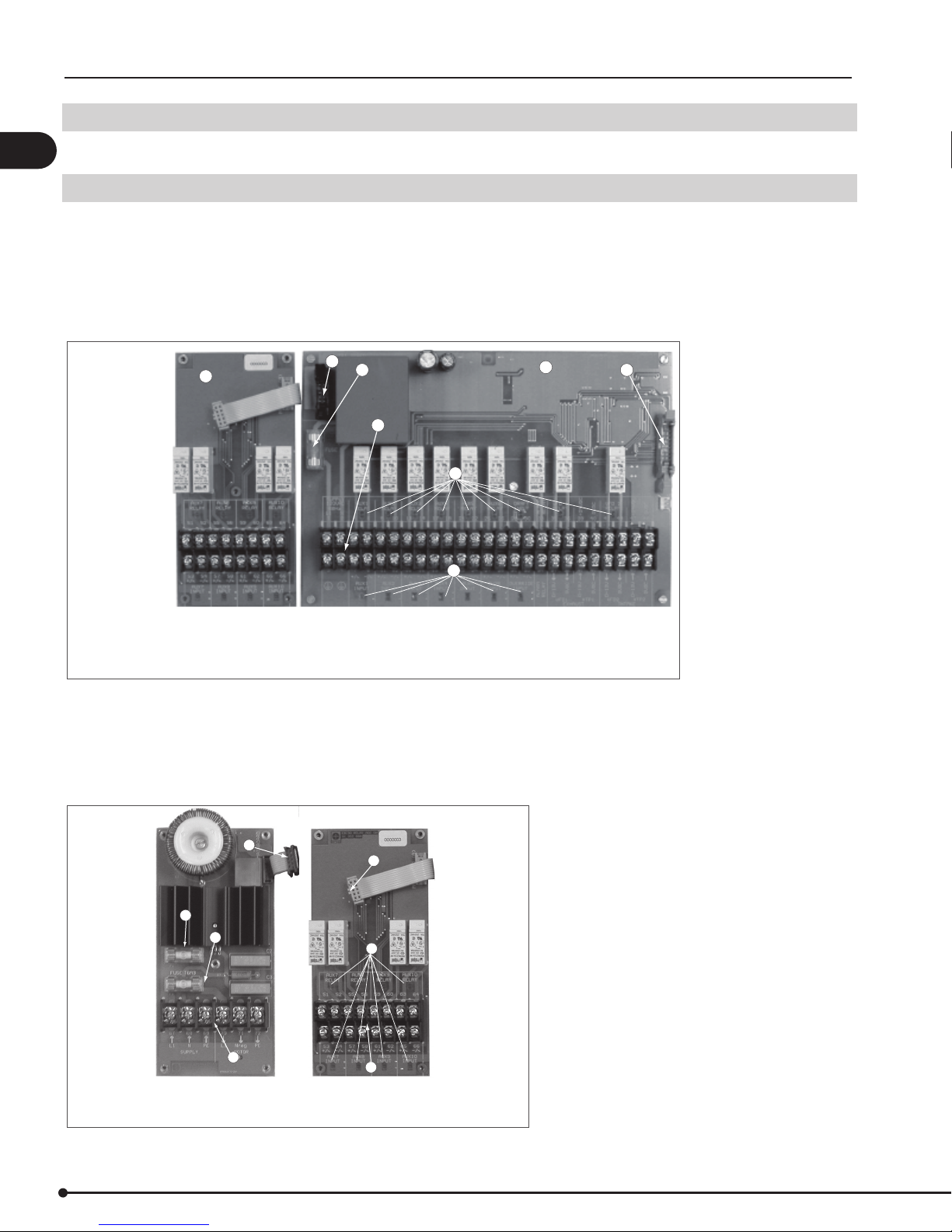
The main board layout is shown below in g. 1:
Main Board
Fig. 1
2
1. Mainboard
2. Relay Board or Triac Board (optional)
3. Terminals
4. Fuse protection for mainboard
6
4
3
7
7
5. Quick-connect socket to keypad and display
6. Quick-connect socket to add-on board
7. Operating status indicators
1
5
Two add-on boards are available. A Triac board is available so the control can operate a 1 x 120 V fan or ventilator without
the need for an external drive. A Relay Board is available for applications with more than 6 appliances. The control can only
accept a single add-on board at a time. If there is a need for using the Triac board as well as the Relay board, install the Triac
in the EBC30 and use an ES12, Relay Box in lieu of the Relay Board.
Board layouts for the Triac and the Relay Boards are shown below in g. 2:
Triac Board
Fig. 2
3
1. Terminals
2. Fuse protection
3. Spare fuse
4
2
1
4. Quick-connect plug
5. Operating status indicators
Relay Board
4
5
1

4.854.85
2.062.06
EBC30 3002180 100315
2. Specications
2.1 Dimensions and capacities
exodraft EBC30 control
Power supply V 1 x 120 V AC
Amperage A 6.3
Operating temperature °F/°C -4 to 122/-20 to 50
Range of operation inWC/Pa 0-0.6/0-150
Tolerance inWC/Pa 0.01/3 +/-10 %
Control signal mA max. 10
Control relay Max. 120 V AC/8A
Output V AC 10-120
V DC 0-10
Dimensions A in/mm 14.65/372
B in/mm 11.03/280
C in/mm 4.22/107
Weight lbs/kg 8.9/4.0
EMC standard Emission EN 50 081-1
Immunity EN 50 082-2
Ashcroft XTP sensor
Power supply V DC 14-36
Amperage mA 6
Output V DC 0-10
Operating temperature °F/°C 0-160/-17 - 70
Tolerance inWC/Pa +/- 0.8 %
Dimensions D in/mm 2.2/55
E in/mm 4.6/118
F in/mm 4.1/104
G in/mm 4.5/115
Weight lbs/kg .5/.2
Chimney probe
Dimensions H in/mm 4.25/108
I in/mm 3.50/89
5
intake
exhaust
EBC30 3002180 100315
6
3. Mechanical installation
3.1 Location
The control and the transducer must be installed inside, preferably in the mechanical room (boiler room).
The control does not need to be installed in an enclosure. Fig. 3 shows how the components are connected.
The transducer cannot be mounted inside an airtight enclosure.
It uses the boiler room pressure as reference pressure.
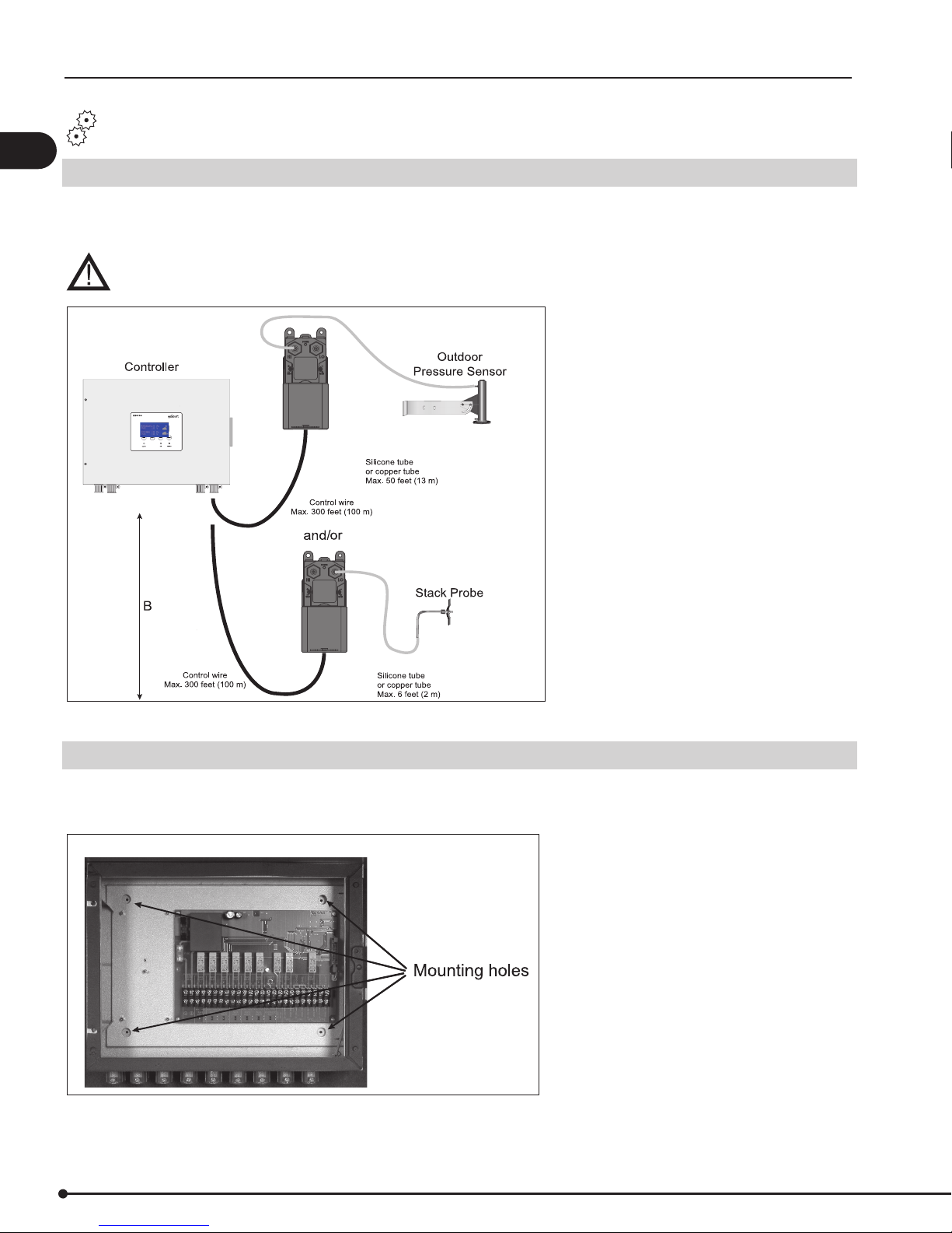
Fig. 3
3.2 Mounting of control
The control can be mounted directly on a wall or similar. The mounting holes are located inside the control as shown in
Fig. 4. The distance between the control and the transducer should not exceed three hundred (300) feet.
Fig. 4
 Loading...