

Exodraft EBC24 Series, EBC24EU01, EBC24EU02, EBC24 Fitting, Installation And Operating Instructions
Page 1
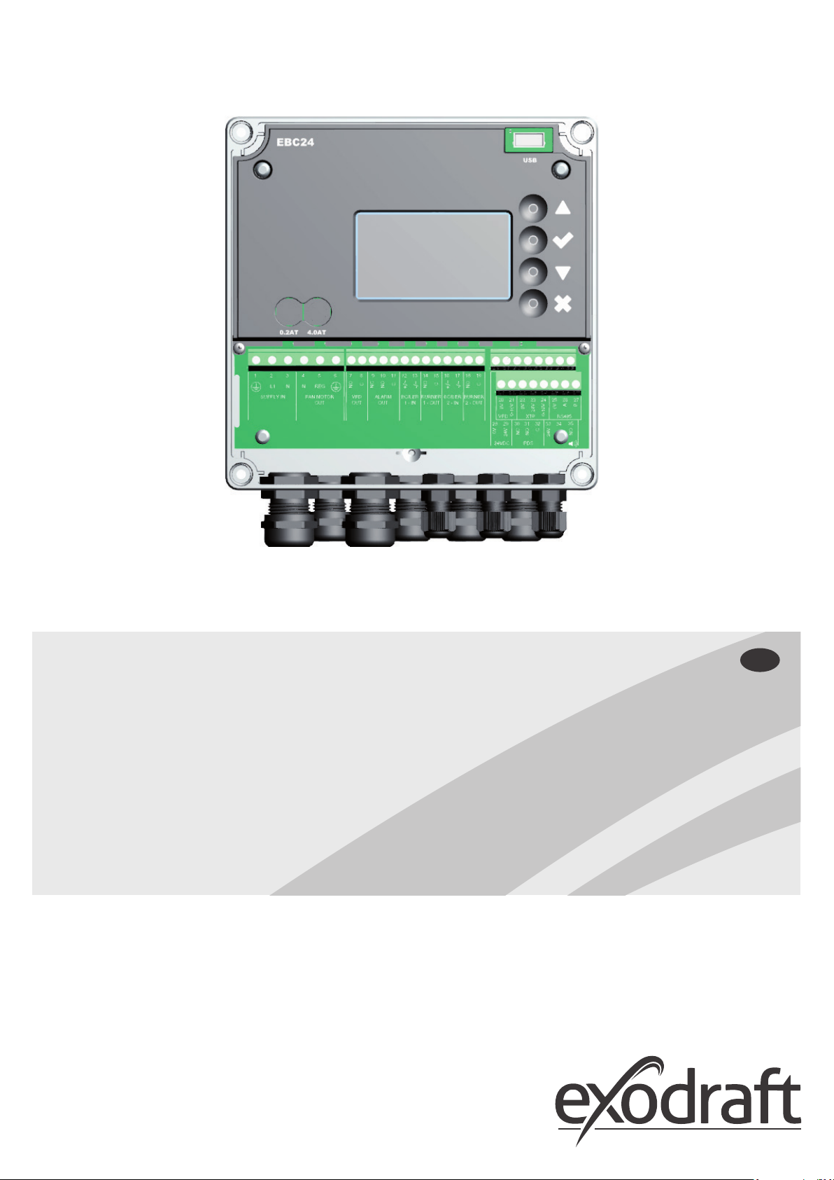
EBC24
Fitting, installation
and operating instructions
Read and save these instructions!
UK
Page 2

2
3120073-UK EBC24
1. Specications .............................................................................................4
1.1 Dimensions and capacity ...................................................................................4
2. Product information .......................................................................................5
2.1 Accessories ................................................................................................6
2.2 Fitting .....................................................................................................6
2.2.1 Connection diagram . . . . . . . . . . . . . . . . . . . . . . . . . . . . . . . . . . . . . . . . . . . . . . . . . . . . . . . . . . . . 7
2.3 Layout of the user interface .................................................................................8
2.3.1 Panel . . . . . . . . . . . . . . . . . . . . . . . . . . . . . . . . . . . . . . . . . . . . . . . . . . . . . . . . . . . . . . . . . . . . . . 8
2.3.2 Terminal board . . . . . . . . . . . . . . . . . . . . . . . . . . . . . . . . . . . . . . . . . . . . . . . . . . . . . . . . . . . . . . . . 9
2.4 Mechanical installation ................................................................................... 10
2.5 Display .................................................................................................. 11
2.5.1 Using the interface . . . . . . . . . . . . . . . . . . . . . . . . . . . . . . . . . . . . . . . . . . . . . . . . . . . . . . . . . . . . 11
2.6 Introduction to the user interface ......................................................................... 12
2.7 Setup .................................................................................................... 13
2.7.1 Chimney draft setting . . . . . . . . . . . . . . . . . . . . . . . . . . . . . . . . . . . . . . . . . . . . . . . . . . . . . . . . . . 13
2.8 Pre/post-purge ........................................................................................... 14
3. Settings and troubleshooting .............................................................................15
3.1 Error codes ............................................................................................... 15
3.2 Overview of the service menu ............................................................................15
3.2.1 Light-emitting diodes and terminal board . . . . . . . . . . . . . . . . . . . . . . . . . . . . . . . . . . . . . . . . . . . . . 17
3.2.2 Switch between the basic functions of pressure control and supply air . . . . . . . . . . . . . . . . . . . . . . . . . . . 18
4. Pressure regulation of exodraft chimney fans ..............................................................19
4.1 Application .............................................................................................. 19
4.2 Functioning .............................................................................................. 19
4.3 Electrical connection ..................................................................................... 19
4.4 Wiring examples ......................................................................................... 19
4.4.1 One boiler . . . . . . . . . . . . . . . . . . . . . . . . . . . . . . . . . . . . . . . . . . . . . . . . . . . . . . . . . . . . . . . . . . 20
4.4.2 One boiler with potential free contact . . . . . . . . . . . . . . . . . . . . . . . . . . . . . . . . . . . . . . . . . . . . . . . . 21
4.4.3 One boiler and extra monitoring with PDS . . . . . . . . . . . . . . . . . . . . . . . . . . . . . . . . . . . . . . . . . . . . . 22
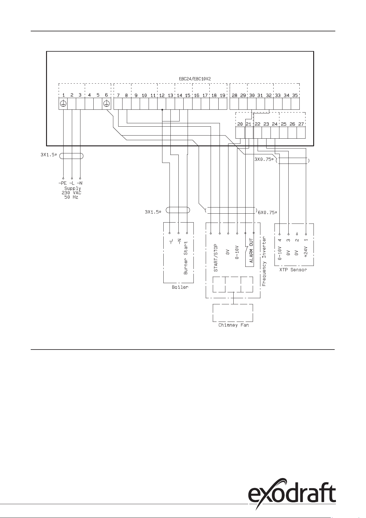
4.4.4 One boiler connected to frequency converter . . . . . . . . . . . . . . . . . . . . . . . . . . . . . . . . . . . . . . . . . . . 23
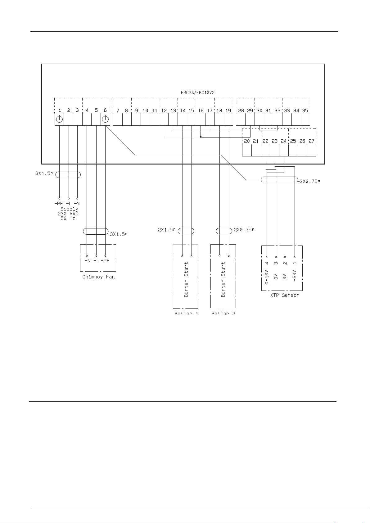
4.4.5 Two boilers with continuous operation of chimney fan . . . . . . . . . . . . . . . . . . . . . . . . . . . . . . . . . . . . . 24
5. Pressure regulation of supply air fan .......................................................................25
5.1 Application ..............................................................................................25
5.2 Mode of operation ....................................................................................... 25
5.3 Electrical connection ..................................................................................... 25
5.4 Wiring examples ......................................................................................... 25
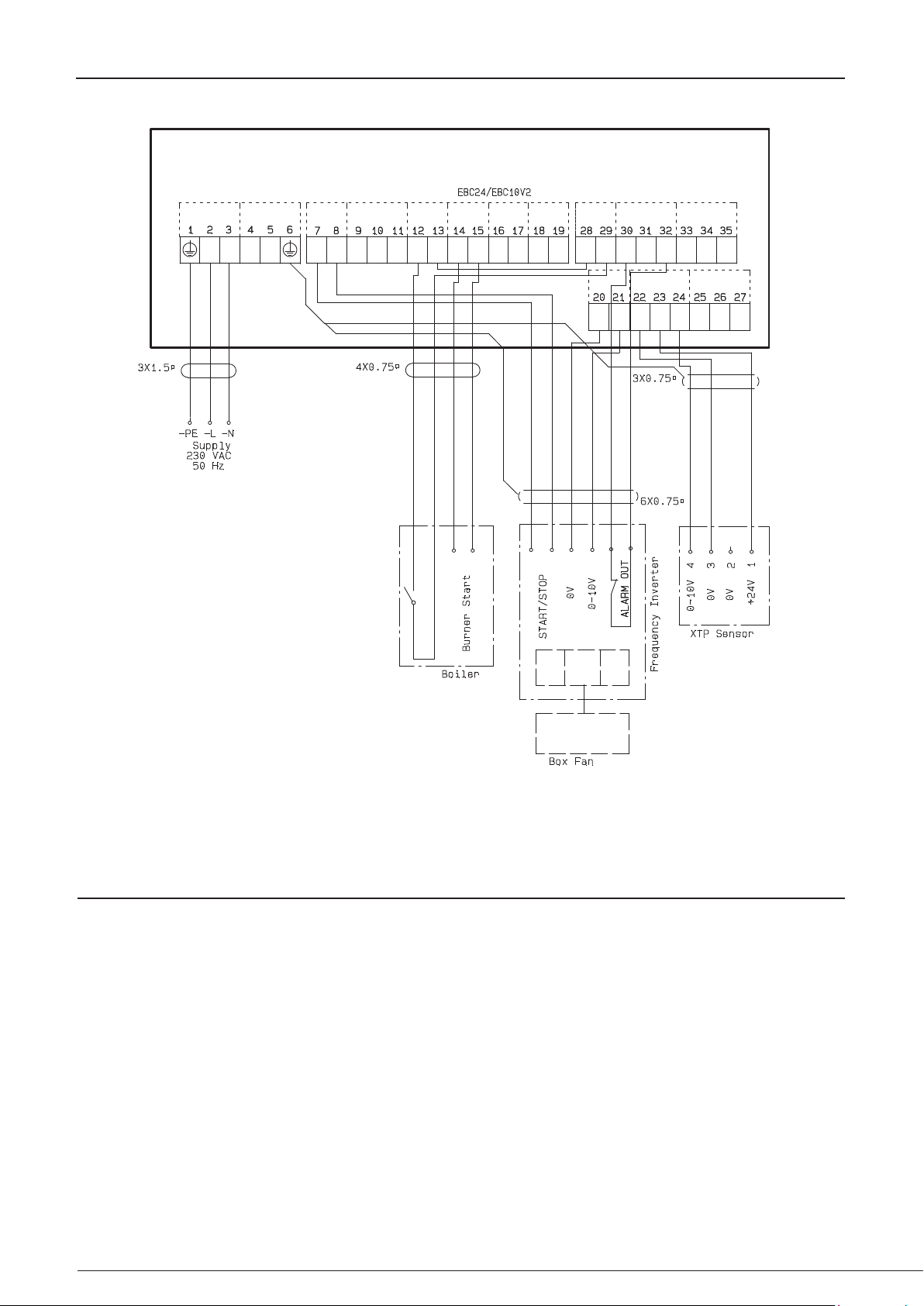
5.4.1 Connection of frequency converter/MPR-relay . . . . . . . . . . . . . . . . . . . . . . . . . . . . . . . . . . . . . . . . . . 26
6. EU Declaration of Conformity .............................................................................27
Page 3
3120073-UK EBC24
Symbols:
The following symbols are used throughout this manual to bring attention to potential danger or to important
information about the product.
Prohibition symbol:
Failure to observe instructions marked with a prohibition symbol is associated with serious injury or death.
Danger symbol:
Failure to observe instructions marked with a danger symbol is associated with personal injury or material
damage.
TO REDUCE THE RISK OF FIRE, ELECTRICAL SHOCK, OR INJURY, OBSERVE THE FOLLOWING:
• Use this unit in the manner indicated by the manufacturer. If you have questions, contact the supplier.
• Before servicing the unit: Switch of the power and ensure that no one can turn it back on accidentally.
• Installation work should be done by qualied individuals according to applicable statutory regulations.
• Follow directions of the manufacturer along with general safety guidelines.
• This unit must be grounded during installation.
3
Disposal:
No special disposal requirements. Disposal of this product should be carried out in accordance with statutory
regulations regarding electronic waste.
Installation: ________________________________
Installer: _________________________________
Installation Date: ____________________________
Page 4
4 • Technical specications
1. Specications
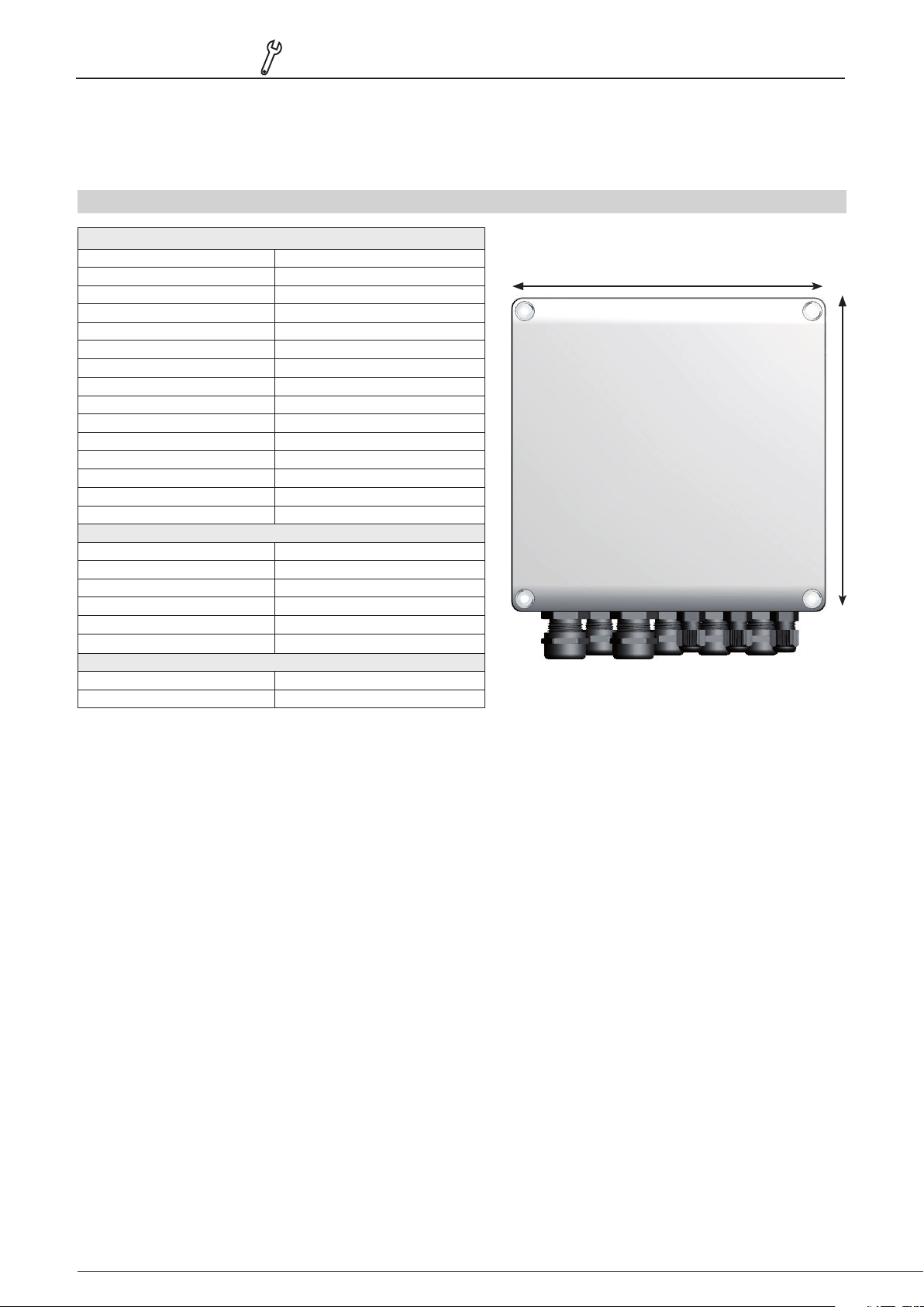
1.1 Dimensions and capacity
exodraft EBC24 Styring
Power supply V 1x 230 V / 50 Hz
Max. motor load kW/hp 0.35/0.5
Operating temperature °C -20 to 50
Selection of operations Pa 0-150
Tolerance Pa +/-5%
+24V supply mA 100 Max.
Control signal VFD VDC/mA 0-10 / Max. 10
Control and alarm relay Max 230 VAC/4A AC1 - 24 VDC/2A DC1
Boiler inputs 10-48 VDC / 10-230 VAC
VFD Relay Max 230 VAC/2A AC1 - 24VDC/2A DC1
Output TRIAC VAC 10-230
Dimensions AxBxC 175 x 175 x 100 mm
Weight kg 1.5
IP-rating IP 54
Fuse A 4.0T
XTP-150 sensor
Power supply VDC 24 VDC(+/- 15%)
IP-Rating IP 54
Output VDC 0-10 VDC, max 10 mA
Operating temperature °C -17 to 70
Tolerance Pa +/-5%
Dimensions mm 80 x 82 x 55,5
Chimney Probe
Dimensions H mm 108
I mm 89
3120073-UK EBC24
A
B
Page 5

3120073-UK EBC24
Product information • 5Product information • 5
2. Product information
Description
EBC24 (exodraft Boiler Control) is a specially developed control component for constant pressure regulation of chimney
draft. Available in two variants:
• EBC24EU01 is suitable for indoor installation
• EBC24EU02 is suitable for outdoor installation
By changing the setup, EBC24 can also:
• Regulate the supply of fresh air to the boiler room (see section 4).
Guide structure
EBC24 can be used either to control exodraft chimney fans or to control supply air fans.
The guide is divided into six sections::
• Section 1. Specications
• Section 2. ”Product Information”.
• Section 3: Settings and Troubleshooting
Section 4: Pressure control of exodraft chimney fans (default setting).
• EBC24 ensures and monitors consistent pressure in the chimney.
• EBC24 can also be used for boiler systems with modulating burners.
• The automation monitors the draft in the chimney, disabling the burner in case of malfunction.
• The automation is designed for both solid fuel boilers, atmospheric gas boilers, and boilers with oil and
gas blow torches.
• EBC24 can control a chimney fan directly or indirectly via a frequency converter.
Section 5: Pressure control of supply air fan.
• EBC24 is used for control of a supply air fan.
• EBC24 ensures and monitors consistent pressure in the boiler room.
• The automation monitors the pressure in the boiler room, disabling the burner in case of malfunction.
• EBC24 can control a supply air fan directly or indirectly via a frequency converter.
Section 6: EU Declaration of Conformity
Page 6
6 • Product information6 • Product information
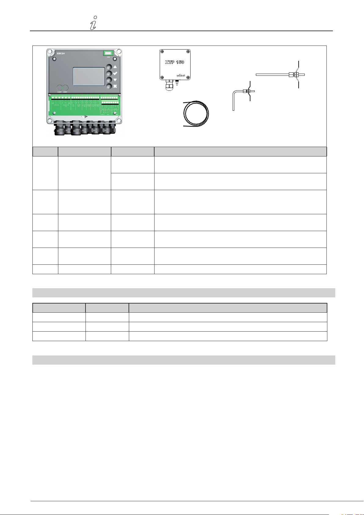
EBC24 includes the following:
3120073-UK EBC24
B
D
E
C
A
Pos. Part Item no. Function
A EBC24 EBC24EU01 Control of exodraft chimney fans and blow fans. For indoor
installation.
EBC24EU02 Control of exodraft chimney fans and blow fans. For outdoor
installation.
B Pressure
transducer (XTP)
C Measuring probe
for EBC24EU01
D Measuring probe
for EBC24EU02
E 2 m. Silicone hose 2000335 Supplies the pressure transducer (XTP) with reference pressure
Instructions 3120070
XTP150 Measures the air pressure in boiler room, chimney, or outdoor
atmospheric pressure.
3200814 Measures pressure in the chimney. (EBC24EU01)
3200813 Measures pressure in the chimney. (EBC24EU02)
from the measuring probe or from outdoors.
2.1 Accessories
Part Item no. Function
Relay ES12 For connection of more than two boilers
External PDS PDSBOX Measures pressure in the chimney
Rep. switch REP-AFB Isolation switch
2.2 Fitting
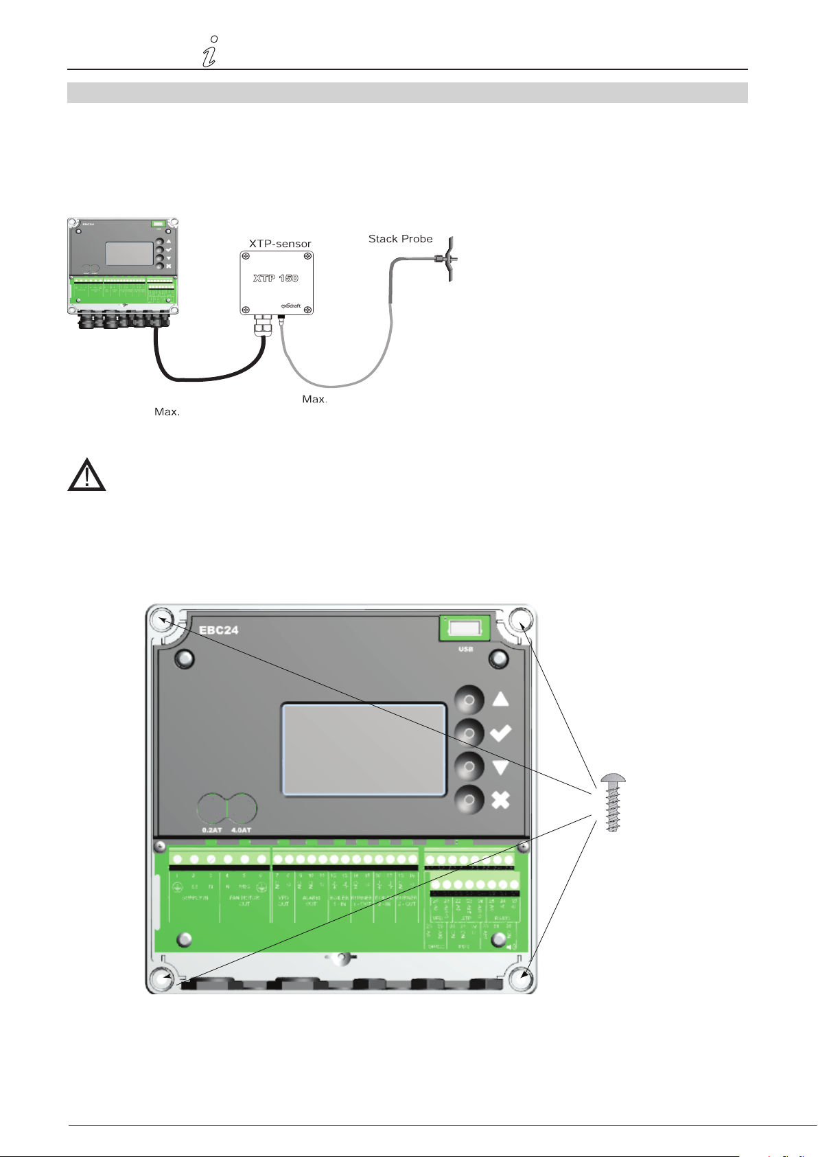
Cable length
Max. cable length between EBC24 and XTP: 100 m.
Max. cable length between EBC24 and chimney fan / fan: 100 m.
Max. cable length between XTP and measuring probe 2m.
Page 7
B1
3120073-UK EBC24
2.2.1 Connection diagram
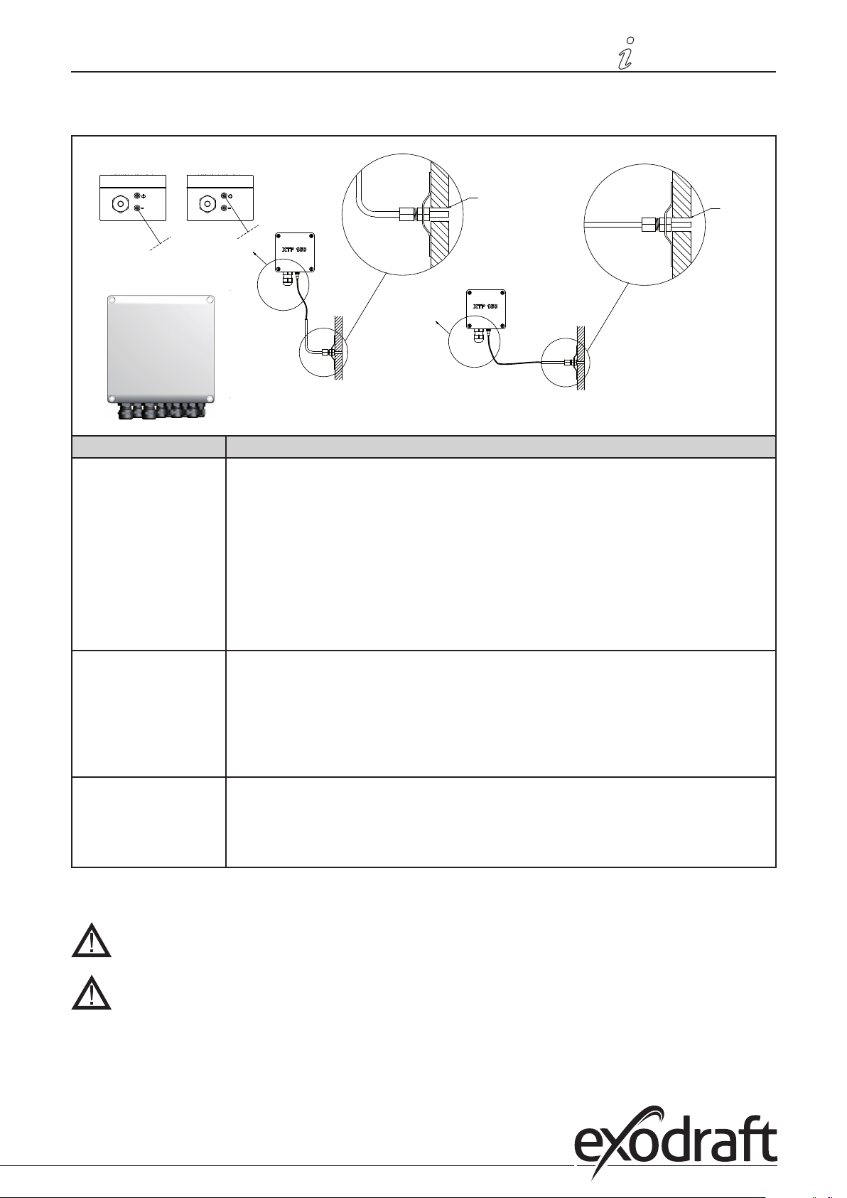
EBC24 is to be tted and connected as shown in the diagram below.
Product information • 7Product information • 7
B2
EBC24
A
Control of. Fitting procedure
Chimney fan
Note!
• Install EBC24EU01 and the pressure transducer (XTP) in the boiler room.
• Fit the measuring probe (A) in the boiler ue or in the manifold. However, for atmospheric boilers, the probe must always be positioned after the draft hood.
• Connect the hose from the measuring probe to the negative terminal on the pressure
transducer “B1”.
• When the measuring probe is placed outside, it must be installed in a manner that prevents the formation of condensation or ice. EBC24EU02 comes with a straight measuring
probe.
• EBC24 must always be installed where it is protected from wind and weather (rain, snow,
etc.)
A
Ø 6.5
A
Ø 6.5
A
Supply air fan • Install the control and the pressure transducer (XTP) in the boiler room.
• Connect the hose for measuring reference pressure (outdoor atmospheric pressure) to
the negative terminal “B1” on the pressure transducer. Run the hose outside the building
to a place not exposed to the weather. The open end of the hose may be installed inside
a box as described at the top of the next page.
Note! • Particularly when wanting positive pressure* in the chimney / boiler room:
• Connect the hose to the positive terminal on the pressure transducer “B2”.
• EBC24 comes with only 2 m of hose.
Note!
*The default setting of the EBC24 is for negative pressure regulation, but local statutory
regulations may require constant positive pressure.
**Do not install the pressure transducer in an airtight enclosure, as it uses the atmospheric
pressure for reference..
Page 8
8 • Product information8 • Product information
3120073-UK EBC24
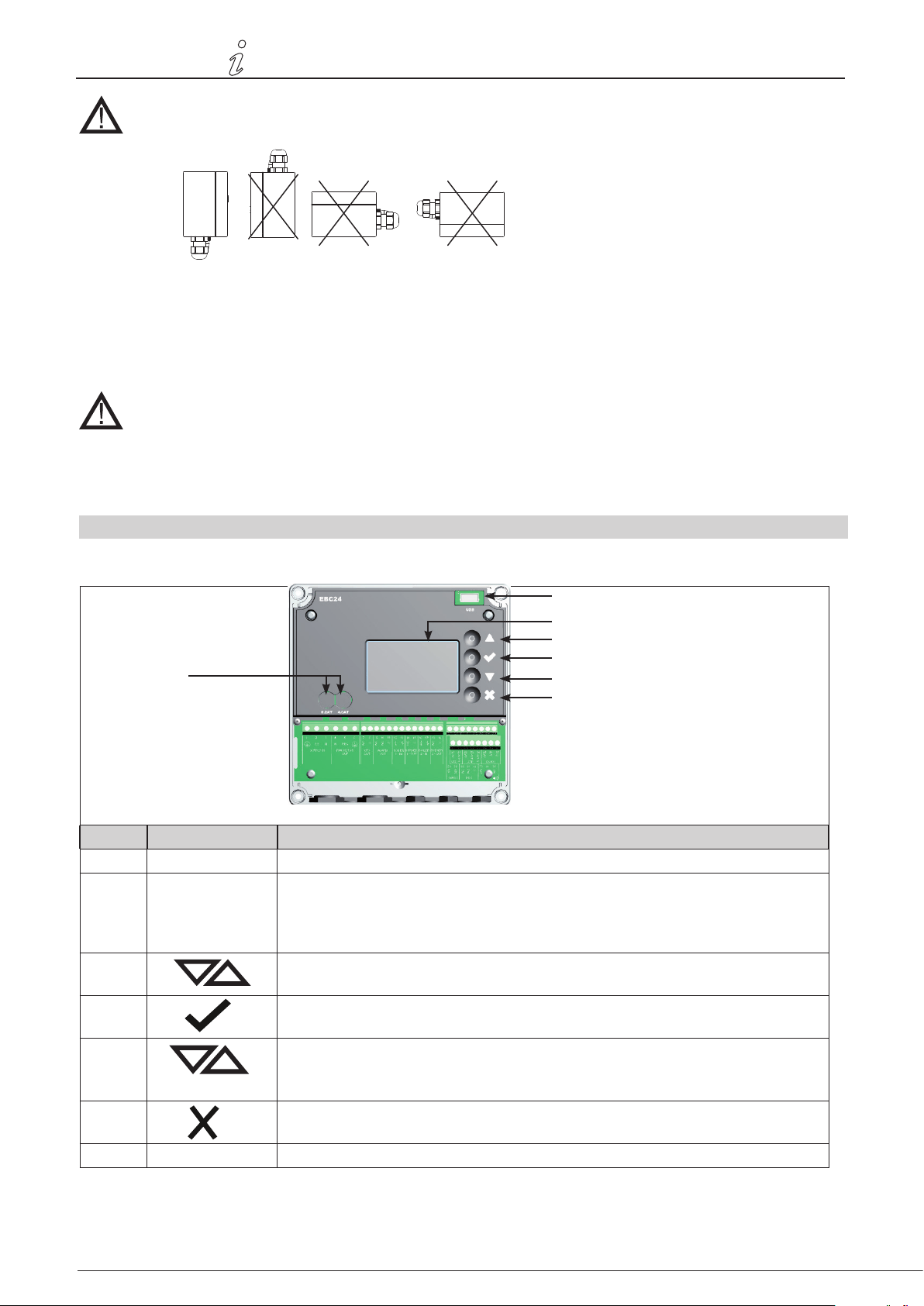
Make sure to position the pressure transducer (XTP) correctly.
Note
Do not blow into the valves of the XTP.
For outdoor installation, place the pressure transducer where it is not exposed to the weather. For outdoor
installation, the pressure transducer should be placed in a box tted with a hole (Ø2mm) in the bottom. The
hole serves to ensure correct reference pressure and prevent water entry
If the pressure transducer is positioned where insects have access to the free end, installing a sinter lter is
recommended
2.3 Layout of the user interface
2.3.1 Panel
G
Pos. Del Funktion
A USB • USB Interface
B Display • Shows operation and changes in the user interface (menu system)
• Indicates alarms
• shows normal operation status
C
D • Approves your action
E • Go down in the menu system
• Go forward/up in the menu system
• Increase set point
• Forward
• Reduce set poin
A
B
C
D
E
F
F
G Fuse • Fuse type
• Interrupt action
• Back
Page 9
3120073-UK EBC24
Product information • 9Product information • 9
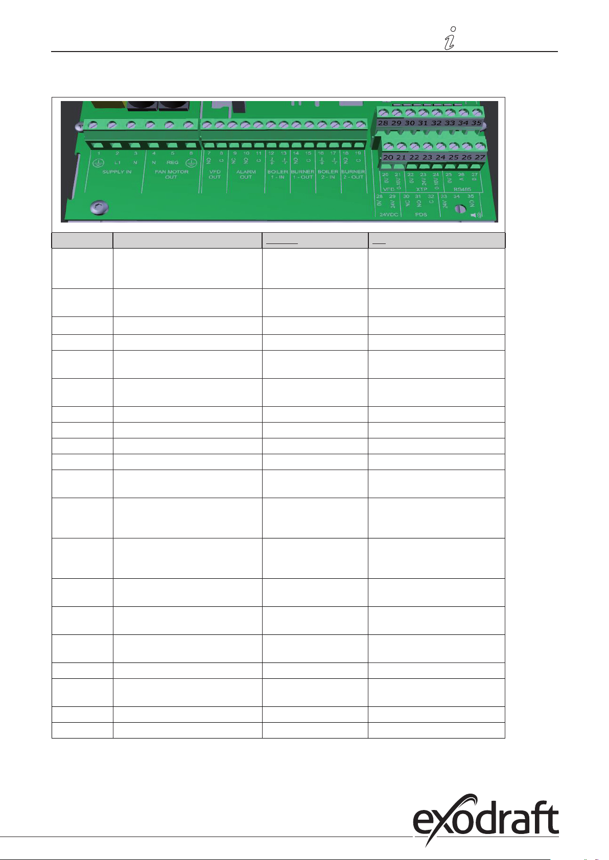
2.3.2 Terminal board
The following explains connection options for the terminal board
Terminal Betegnelse
Terminal Use
1 PE Ground 18 Burner 2 relay switch-Nor-
mally open (max. 230 VAC, 2
amps.)
2 Supply - L1 19 Burner 2 relay switch-Regular
(max. 230 VAC, 2 amps.)
3
Supply – N
20 Control signal VFD 0V DC
4 Chimney fan – N 21 Control signal VFD 0-10V DC
5 Chimney fan - L1 (Regulating) 22 XTP-0V DC power supply
(transducer)
6 Chimney fan - PE Ground 23 XTP-24V DC power supply
(transducer)
7 Frequency converter relay NO 24 RS485 0V
8 Frequency converter relay C 25 RS485 A
9 Alarm Out - NC 26 RS485 B
10 Alarm Out - NO 27 0V DC Power supply
11 Alarm Out - C 28 24 VDC power supply (Max.
100 mA)
12 Voltage input from appliance /
boiler 1 thermostat optocoupler
29 24 VDC power supply (Max.
100 mA)
(+) (10-230V AC/DC
13 Voltage input from appliance /
boiler 1 thermostat optocoupler
30 PDS-NC (normally closed)
Proven draft switch
(-) (10-230V AC/DC
14 Burner 1 relay switch-Normally
open (max. 230 VAC, 2 amps.)
15 Burner 1 relay switch-Regular
(max. 230 VAC, 2 amps.)
16 Voltage input from appliance /
31 PDS-NO (normally open) Prov-
en draft switch
32 PDS-C (shared) Tested draft
switch
33 Buzzer-24V DC supply
boiler 2 thermostat optocoupler
17 (+) (10-230V AC/DC) 34 Not used
Voltage input from appliance /
35 Buzzer Signal
boiler 2 thermostat optocoupler
(-) (10-230V AC / DC)
* Cable length between 0-10V output (terminals 20 and 21) must not exceed 100 m of shielded cable 3 x 0,75 mm2.
** However, terminals 30, 31, and 32 may be used for connecting other auxiliary monitoring equipment as well.
Page 10
100 m
2 m
EBC24 Control
10 • Product information10 • Product information
3120073-UK EBC24
2.4 Mechanical installation
The control and the transducer must be installed inside, preferably in the boiler room. The control does not need to be
installed in a cabinet.
Do not install the transducer in an airtight enclosure. It uses the boiler room pressure / atmospheric pressure
as reference pressure.
The control can be installed directly on the wall or somewhere similar.
Take o the lid.
The installation holes are placed under the plastic screws keeping the cover in place.
The distance between the control and the transducer should not exceed 100 m.
Page 11
3120073-UK EBC24
Product information • 11Product information • 11
2.5 Display
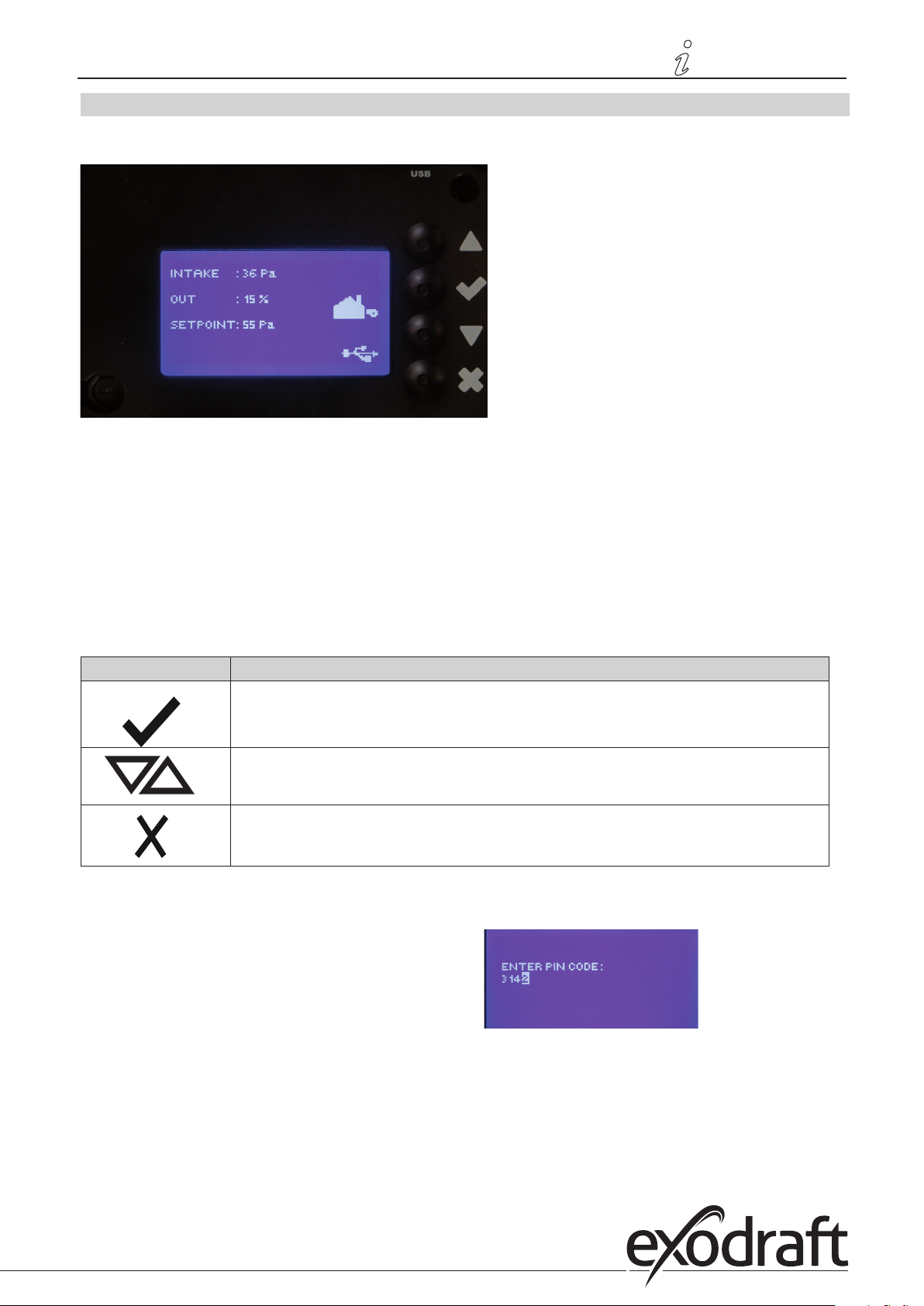
The diagram below shows the layout of the display on the EBC24. All possible display values are indicated:
The purpose of the display is to indicate:
• Operating information (pressure, etc.)
• Alarms
• Parameters
• Set points
• USB
2.5.1 Using the interface
The user interface is operated via four buttons with the following functions:
Tast Funktion
• Activate the service menu (press and hold for 5 seconds and enter code: 3142)
• Edit and save settings
• Go to menu item and adjust value
• Return to operation screen from any point in the menu system
• Reset alarm when “Manual Reset” is selected in menu 2.3.
Access to the service menu
• Activate service menu (press and hold for 5 seconds)
• Enter code 3142
• Adjust value using the arrows.
Page 12
12 • Product information12 • Product information
2.6 Introduction to the user interface
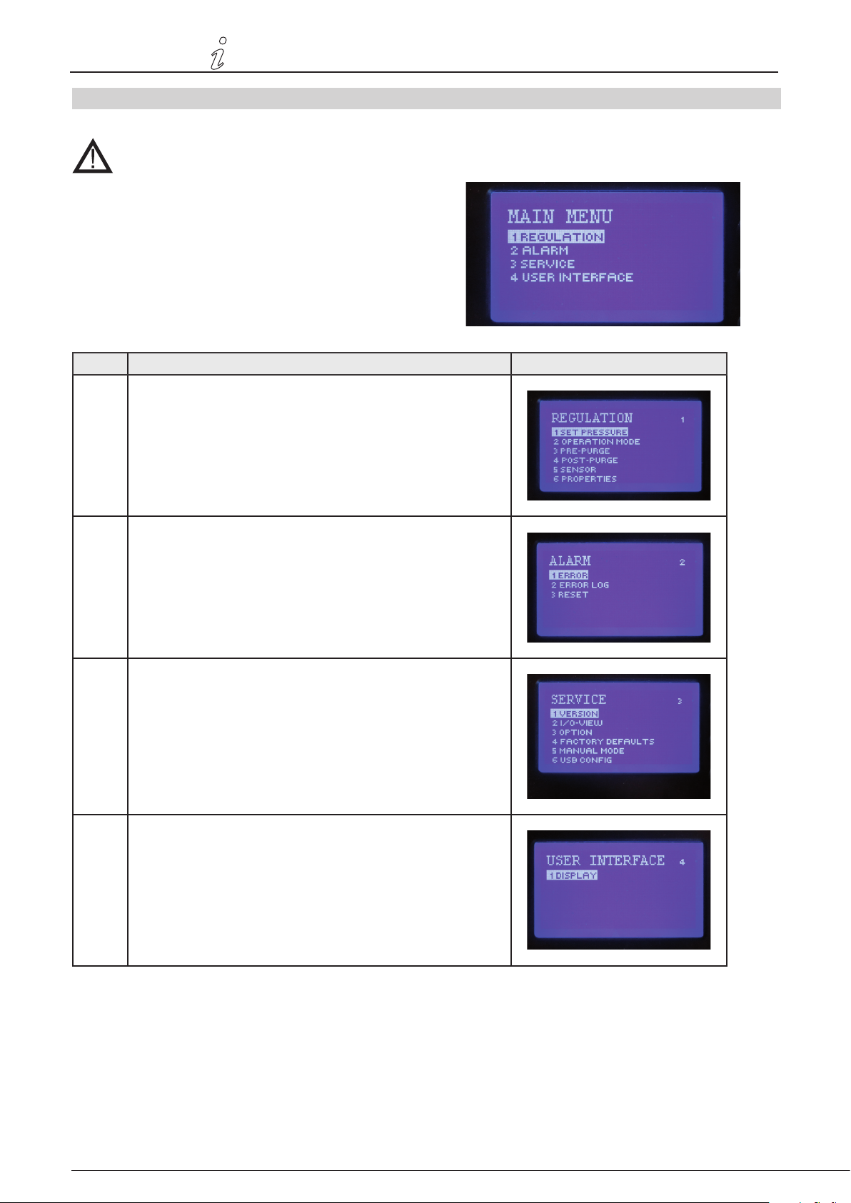
Menu structure
Only qualied personnel should use the service menu
The service menu consists of four main menus, each divided
into submenus.
• 1. Regulation
• 2. Alarms
• 3. Service
• 4. User interface
Function description Display indicates
Menu: 11.1 Pressure regulation: 0-95%: 0-150 Pa
1.2 Operating mode: Continuous or Intermittent
1.3 Pre-purge: Time and speed mode
1.4 Post-purge: Time and speed mode
1.5 Sensor: Range min. and max.
1.6 Properties: See page 15 (2.9 Service menu overview)
3120073-UK EBC24
Menu: 22.1 Error: Alarm type
2.2 Error log: Alarm log covering 19 readings
2. 3 Reset: Automatic or manual
Menu:33.1. Version no.
3.2 I/0-view: Input/output monitor/activator
3.3 Option: Bearing cycle, prime, draft input delay.
3.4 Factory presets: Default settings
5 Manual mode: TRIAC/frequency converter output 0-100%
6 USB cong: Updating of rmware, conguration les
Menu: 44.1: Display: Language, units, and LCD settings
See page 15 (2.9 Service menu overview) for detailed overview
Page 13
3120073-UK EBC24
2.7 Setup
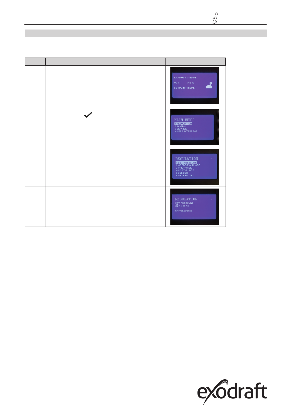
2.7.1 Chimney draft setting
To set the pressure in the chimney, follow the procedure detailed below:
Trin Handling Display viser
1
• Start the system
• EBC24 displays the actual negative pressure (in this
example, 55 Pa)
Product information • 13Product information • 13
2
• Press and hold for 5 seconds to get into the
service menu
• Enter code: 3142
• Select menu 1
3
• Select menu 1.1
4
• Set required pressure
Note
This procedure only covers setting the pressure in the chimney.
Page 14
14 • Product information14 • Product information
2.8 Pre/post-purge
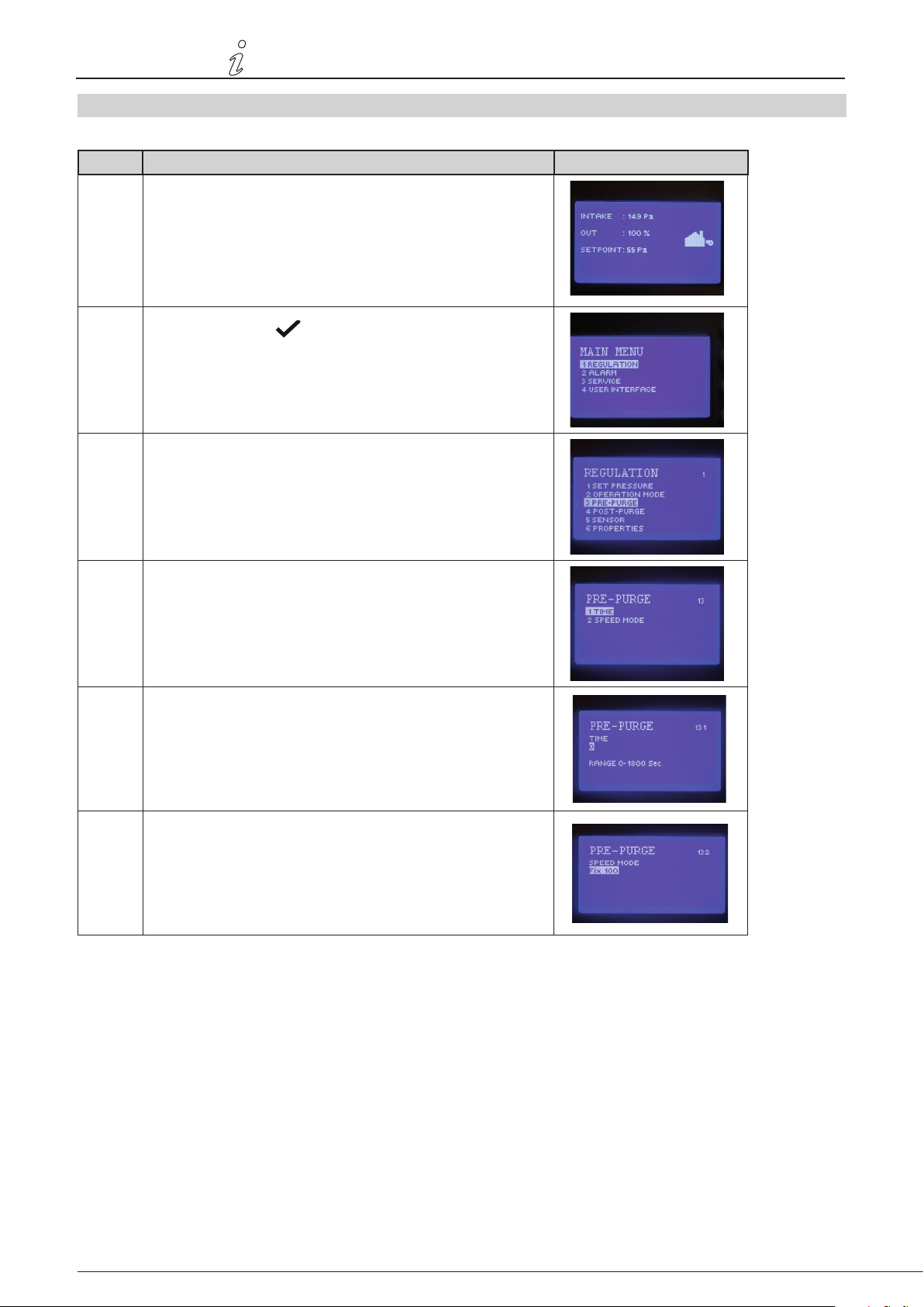
To set up pre-/post-purge period, follow procedure below:
Trin Handling Display viser
1
• Start the system
• EBC24 displays the actual negative pressure (in this example, 55 Pa)
3120073-UK EBC24
2
• Press and hold for 5 seconds to get into the service
menu
• Enter code: 3142
• Select menu 1
• w
3
• Regulation 1
• Select menu 1.2 Pre-purge
• Select menu 1.3 Post-purge
4
• Select either 1.3.1 Time or 1.3.2 speed mode
5 • Set the desired time in seconds
• 0-1800 seconds
6 • Fix 20-100
• or variable
• Finish and return to operation screen with
Page 15
3120073-UK EBC24
Product information • 15Product information • 15
3. Settings and troubleshooting
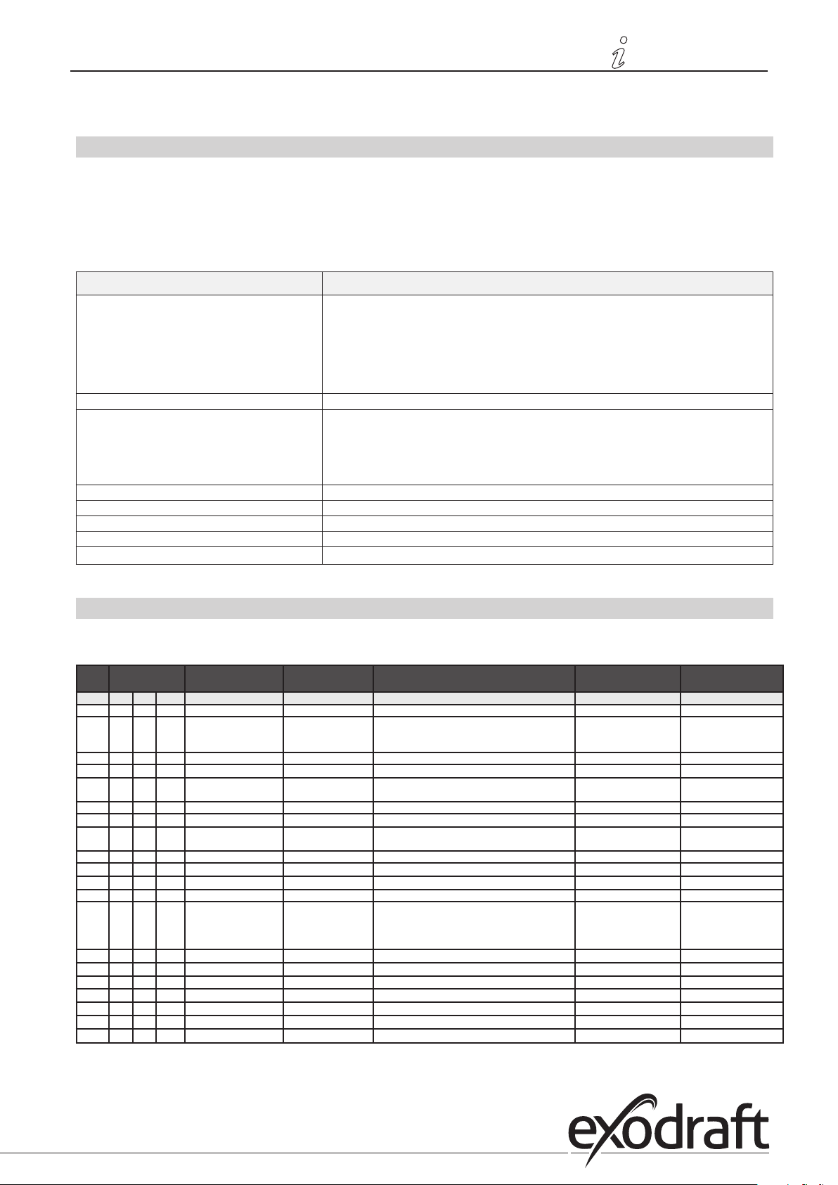
3.1 Error codes
Most terminal connections are monitored for correct operation. An LED light indicates operating status. If a light comes
on, it is an indication that everything is functioning correctly, while a light going out indicates a problem in the circuit it
monitors. In addition, error codes are shown on the display.
The error codes are:
Display Explanation
A1 Draft Exhaust Insucient pressure may be due to:
1. Chimney fan has insucient capacity
2. Mechanical or electrical fan failure
3. Blocked chimney
4. Introduction of excessive dilution air
5. XTP sensor not responding correctly
A2 Power Fault Indicates that there has been a power fault
A3 XTP-Exhaust Indicates a disconnected signal from the XTP sensor on the exhaust side to the control. May
A4 Error Start Indicates that the control has been unable to release the burner within 15 minutes.
A5 Alarm Override Indicates alarm has been disregarded
A6 Draft Input Missing signal from PDS function. Indicates a defective function.
A7 RS485 error No communication between EBC24 and modbus network
A8 Priority The draft has been insucient and therefore the control has been in priority
be caused by:
1. Lose connections
2. Faulty XTP-sensor
3. Defective controller
3.2 Overview of the service menu
The service menu is built in 4 levels and associated submenus.
Menu Sub-menu Function Display Description Classication Standard
1 Exhaust EXHAUST
11 Draft set point SET EXHAUST Adjustment of exhaust setpoint. 2%-95% af sensor 17%
12 Operation mode EXHAUST MODE Continuous or intermittent operation. In inter-
mittent mode the exhaust fan runs only if one
or more boiler inputs are active.
13 Pre-purge PRE-PURGE Pre-purge settings.
131 Time TIME Pre-purge time in seconds 0-1800 0
132 Operation mode SPEED MODE Select variable if the pre-purge should be con-
trolled by the XTP-sensor or have a xed speed.
14 Post-purge POST-PURGE
141 Time TIME Post-purge settings. 0-1800 0
142 Operation mode SPEED MODE Select variable if the post-purge should be con-
trolled by the XTP-sensor or have a xed speed.
15 Sensor SENSOR
151 Min. pressure RANGE MIN XTP minimum pressure in Pa. -500 – 500 Pa 0
152 Max. pressure RANGE MAX XTP Maximum pressure in Pa. 0 – 1000 Pa 150 Pa
16 Parameters PROPERTIES
161 Alarm limit draft ALARM LIMIT Select the alarm limit of the draft. The value is in
% of the set point.
162 Alarmdelay ALARM DELAY Select a alarm delay from 0-120 seconds. 0 – 120 s 15
163 Min. voltage SPEED MIN Mimimum speed of the fan 0 – MENU 164 15 %
164 Max. voltage SPEED MAX Maksimum speed of the fan. MENU 163-100% 100
165 Xp EXHAUST Xp Proportional gain. 0-30 15
166 Ti EXHAUST Ti Integral gain. 0-30 8
167 Sampling rate SAMPLING RATE Set the sampling rate for the PID Loop 1-10 10
168 Pressure type PRESSURE MODE Positive or negative pressure in the stack. Positive or Negative Negative
Continuous/
Intermittent
Variable / FIX 20-100% FIX 100%
Variable / FIX 20-100% Variable
If 167 = "Negative" ->50
- 80 %.
If 167 = "Positive" -> 150
- 300 %"
Intermittent
64 % (167 = "Negative")
144 % (167 = "Positive")
Page 16
16 • Product information16 • Product information
Menu Sub-menu Function Display Description Classication Standard
3120073-UK EBC24
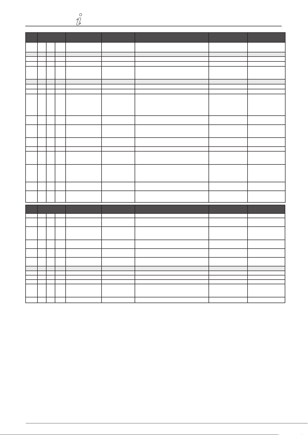
169 Application APPLICATION Sets if the control has to work as Exhaust
or Intake
2 ALARM
21
22
23
Alarm Status
Alarm log
Reset
3 Service
31
32
321 BURNER I/O AUX OUT XXX
322 EXHAUST I/O EXH XTP x.xV OFF
323 Draft input DRAFT INPUT ON/
324 Alarm relay ALARM OUTPUT
33 Options OPTION
331 Bearing cycle BEARING CYCLE Selecting "YES" will enable a bearing cycle on
332 Allow prime Selecting a number from 0-250 will enable the
333 Draft Input Delay DRAFT INPUT DELAY The delay before the control goes into Fraft
34 Factory reset FA CTORY If "YES" is selected, a factory reset will be
Version no.
I/O
ERROR
ERROR LOG The last 10 alarms will be saved in the menu.
RESET Selecting "AUTO" will automatic reset the
SERVICE
VERSION Software version is showed.
I/O-VIEW
AUX IN XX
EXH VFD x.xV OFF
OFF
ON/OFF
The error is shown here
alarm after 15 seconds. If "MAN" is selected,
the "X" has to be pressed.
In this menu the status of the boiler I/O is
shown. By pressing athe AUX OUT relays
can be activated by pressing up and down.
Multiple activations of the a button will move
from relay 1 to 6
XTP, VFD and VFD relay status for Exhaust.
Draft Input I/O status.
Alarm relay output status.
present fans, if the boilers has not been active
for 24 hours.
prime function. This allows the boilers to be
activated even though no sucient draft is
present.
Alarm
performed.
Exhaust / Intake Exhaust
MAN / AUTO AUTO
ON/OFF ON
0-250 s / o O
0-20 s 0 s
YES/NO NO
Menu Sub-menu Function Display Description Classication Standard
36 USB conguration USB CONFIG
361 format USB FORMAT USB Selecting "YES" will format the USB ash drive.
362 Data Log DATA LOG USB /
INTERNAL
363 Save cong. le SAVE CONFIG FILE Slecting "YES" provides the possibility to select
364 Load cong. le LOAD CONFIG FILE Selecting "YES" will download the current
365 Upgrade rmware UPGRADE FIRM-
WARE
4 User Interface USER INTERFACE
41 Display DISPLAY
411 Language LANGUAGE Language. ENG / FRA / ESP ENG
412 Pressure units UNITS Pa or inWC units. Pa / inWC inWC
413 LCD backlight LCD BACKLIGHT LCD backlight turned on or not. The USE param-
414 LCD contrast LCD CONTRAST 10 – 100 % 50
Notice! All data will erased!
Selecting "USB" will store the alarm log on the
USB ash drive, "INT" will store the log in the
internal memory.
congurationles stored on the USB ash drive.
conguration to the USB ash drive.
This function provides the possibility to
upgrade the rmware by means of a USB Stick
eter will cause the backligt to be turned on if a
button is pressed.
YES / NO NO
USB / INT INT
YES / NO NO
YES / NO NO
ON / OFF / USE ON
Page 17
3120073-UK EBC24
Product information • 17Product information • 17
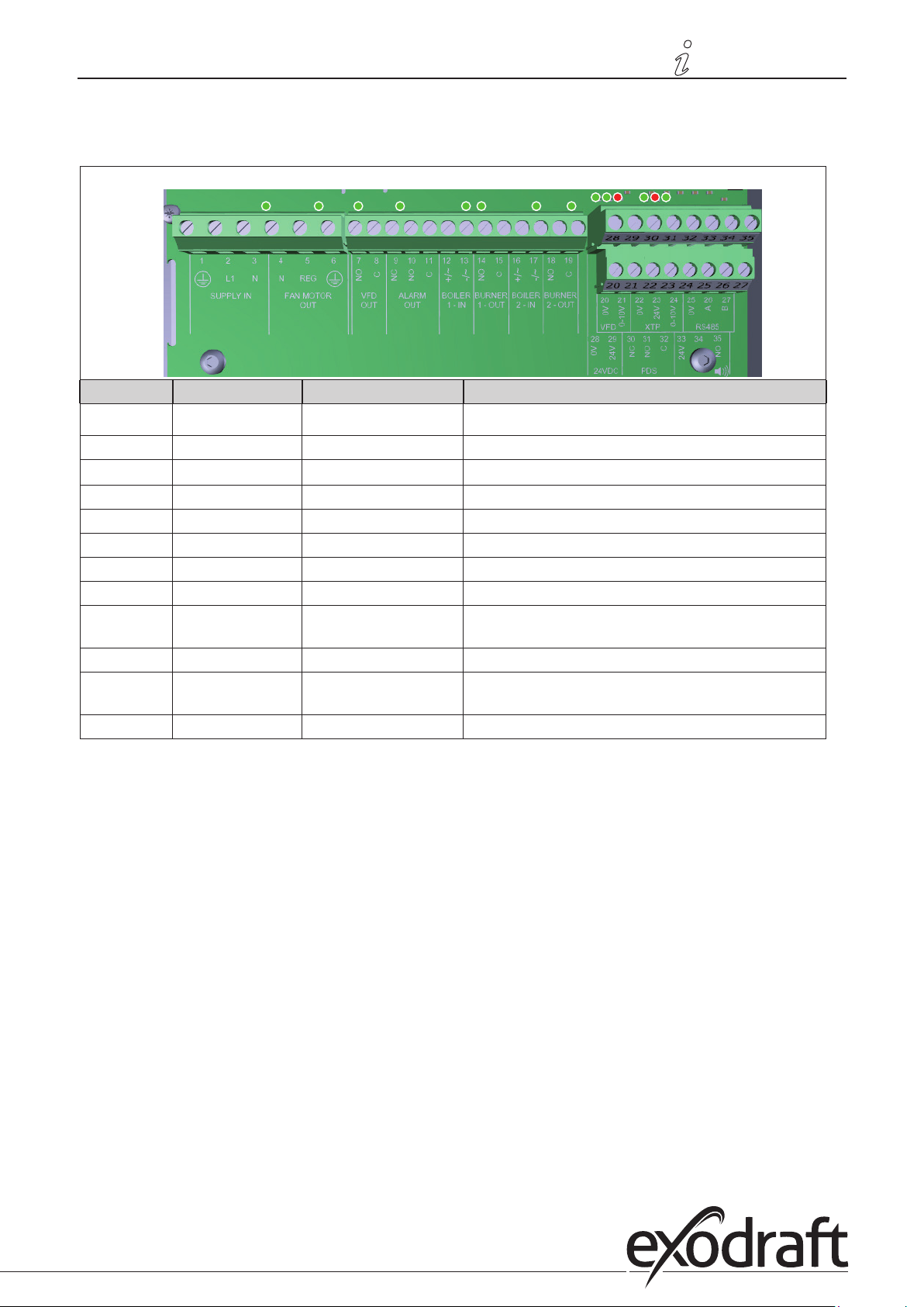
3.2.1 Light-emitting diodes and terminal board
The chart below lists the terminal board connection options and light-emitting diode displays.
No. Designation Max. load Meaning when the light-emitting diode is:
1, 2 og 3 SUPPLY IN 230-240 V AC +/- 10 % green: EBC20 is connected to power supply
4, 5 og 6 FAN OUT 3A green: the Triac output is active
7 og 8
9, 10 og 11 ALARM OUT 250 V AC, 8A, AC3 green: the relay is active
12 og 13 BOILER 1 IN 18 til 230 V DC/V AC green: the input is active
14 og 15 BURNER 1 OUT 250 V AC, 4A, AC3 green: the relay is closed
16 og 17 BOILER 2 IN 18 til 230 V DC/V AC green light: the input is active
18 og 19 BURNER 2 OUT 250 V AC, 4A, AC3 green: the relay is closed
28 og 29 24 V DC OUT 100 mA green: voltage is OK
20 og 21 0 - 10 V OUT* 20 mA green: output is active
22, 23 og 24 XTP IN green: XTP connected
30, 31 og 32 PDS IN ** green: C & NO are closed
VFD OUT
250 V AC, 8A, AC3 green: the relay is closed
red: overload
red: return voltage > 12 V DC
* Cable length between 0-10V output (terminals 20 and 21) must not exceed 100 m of shielded cable 3 x 0,75 mm2.
** However, terminals 30, 31, and 32 may be used for connecting other auxiliary monitoring equipment as well.
Page 18
18 • Product information18 • Product information
3120073-UK EBC24
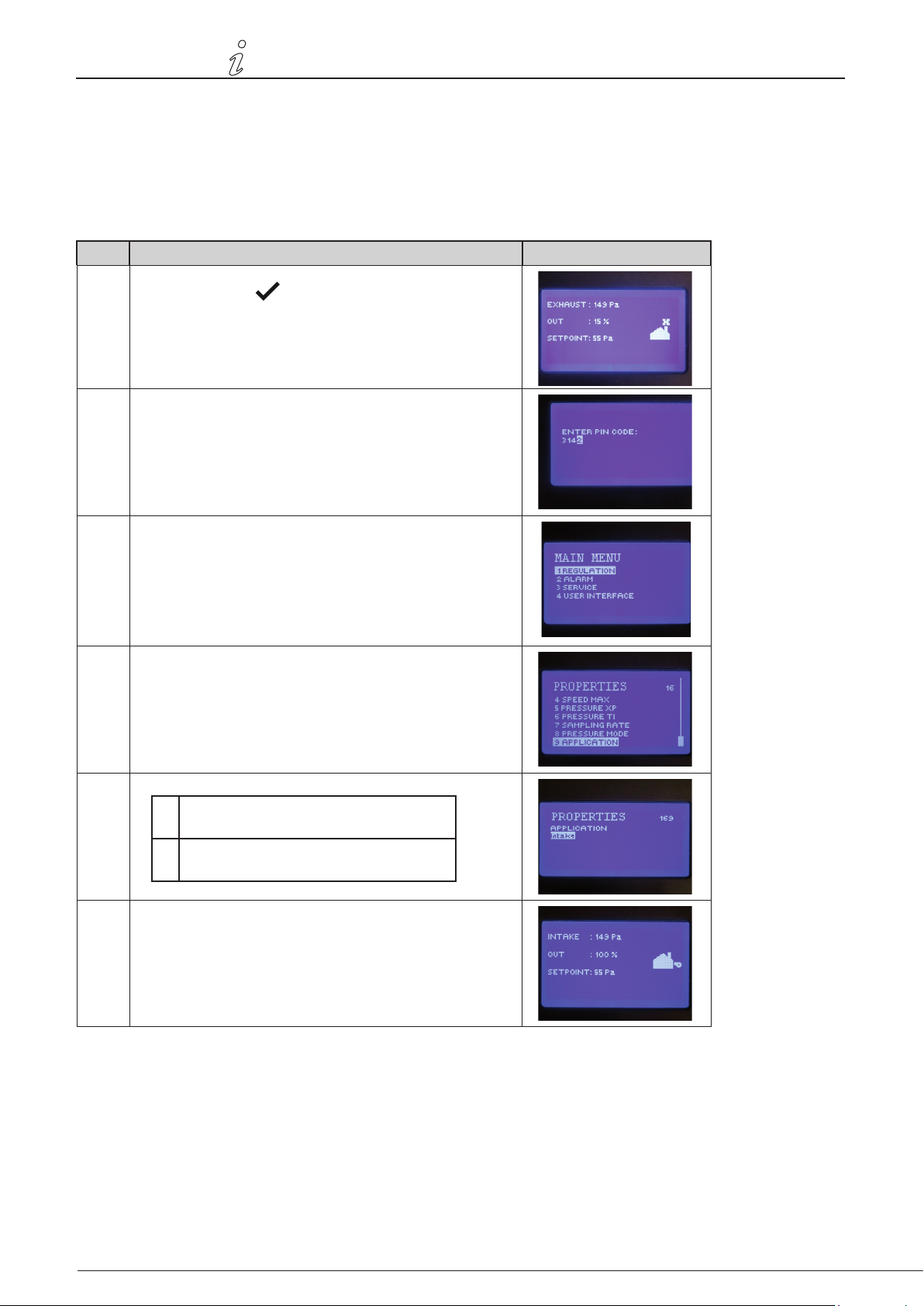
3.2.2 Switch between the basic functions of pressure control and supply air
Default settings
EBC24 defaults to constant pressure regulation of exodraft chimney fans (basic function 1 Exhaust/Intake)
Change of basic function
Step Action Display shows...
1
• Press and hold for 5 seconds
2
• Enter code: 3142
• Use arrows to select followed by
3
• Select menu 1 Regulation
• Select menu 1.6 Properties
4
• Select menu 1.6.9 application
5
1 Pressure regulation of exodraft chimney
fans (Exhaust)
2 Pressure control of Supply air fan
(Indtake)
6
• Finish and return to operation screen
Page 19
3120073-UK EBC24
4. Pressure regulation of exodraft chimney fans
4.1 Application
Field of application
• EBC24 can also be used for boiler systems with modulating burners.
• The automation is designed for both solid fuel boilers, atmospheric gas boilers, and boilers with oil and
gas blow torches.
• EBC24 can control a chimney fan directly or indirectly via a frequency converter.
4.2 Functioning
General function
• The automation monitors the draft in the chimney, disabling the burner in case of malfunction (the alarm
diode on the EBC24 turns on).
• When the boiler thermostat demands heat, the chimney fan will start at max. voltage.
• When the EBC24 registers sucient chimney draft, the burner is released.
• The EBC24 maintains the set pressure by regulating the voltage. The pressure is shown in the display.
• In the event of insucient venting, the burner will initially be disconnected after 15 seconds. Insucient
venting is less than 64% of the set value, corresponding to less than 80% of ow.
• When the boiler turns o, the chimney fan stops as well. It is, however, possible to set a post-purge period
for the chimney fan (see page 23). Alternatively, the control system can be connected in a way that keeps
the chimney fan running continuously (see page 21).
Pressure control • 19
Light-emitting diodes and output signals
All inputs and outputs are connected to a light-emitting diode for monitoring and servicing of the system (see section
2.9.1 Light-emitting diodes and terminal board, page 17)
EBC24 has 0-10V output signals for control of multiple chimney fans via frequency converters or motor power relays.
4.3 Electrical connection
This work must be performed by a qualied electrician in accordance with locally applicable rules and
legislation.
Installation of the supply cable must comply with applicable legislation and regulations.
The grounding terminal (
When connecting a pressure transducer (XTP) and frequency converter, shielded cable must be used.
) must always be connected.
Isolation switch
exodraft a/s stresses that according to EU’s Machinery Directive, an isolation switch must be
incorporated into the xed installation. The isolation switch is not supplied by exodraft, but is available
as an accessory.
4.4 Wiring examples
As a constant pressure regulator for exodraft chimney fans, the EBC24 can be connected to a range of dierent signals.
The following pages are wiring examples and illustrate the following:
• 4.4.1 One boiler, page 20
• 4.4.2 One boiler med potential free contact, page 21
• 4.4.3 One boiler and extra monitoring with PDS, page 21
• 4.4.4 One boiler connected to frequency converter, page 23
• 4.4.5 Two boilers with continuous operation of chimney fan, page 24
exodraft recommends contacting the boiler manufacturer for correct connection to the boiler
automation.
Page 20
SUPPLY IN
VFD Out
L1 N N
FAN MOTOR
OUT
REG
NO
C
NC
NO
C
+/~
-/~
+/~
-/~
NO
C
ALARM OUT BOILER
1 - IN
BURNER
1 - OUT
BOILER
2 - IN
BURNER
2 - OUT
C
NO
24 VDC
0V
24VNCNO
C
24V
NO
PDS BUZZER
VFD
0V
0-10V
0V
24V
0-10V0VA
B
XTP RS485
20 • Pressure control
4.4.1 One boiler
3120073-UK EBC24
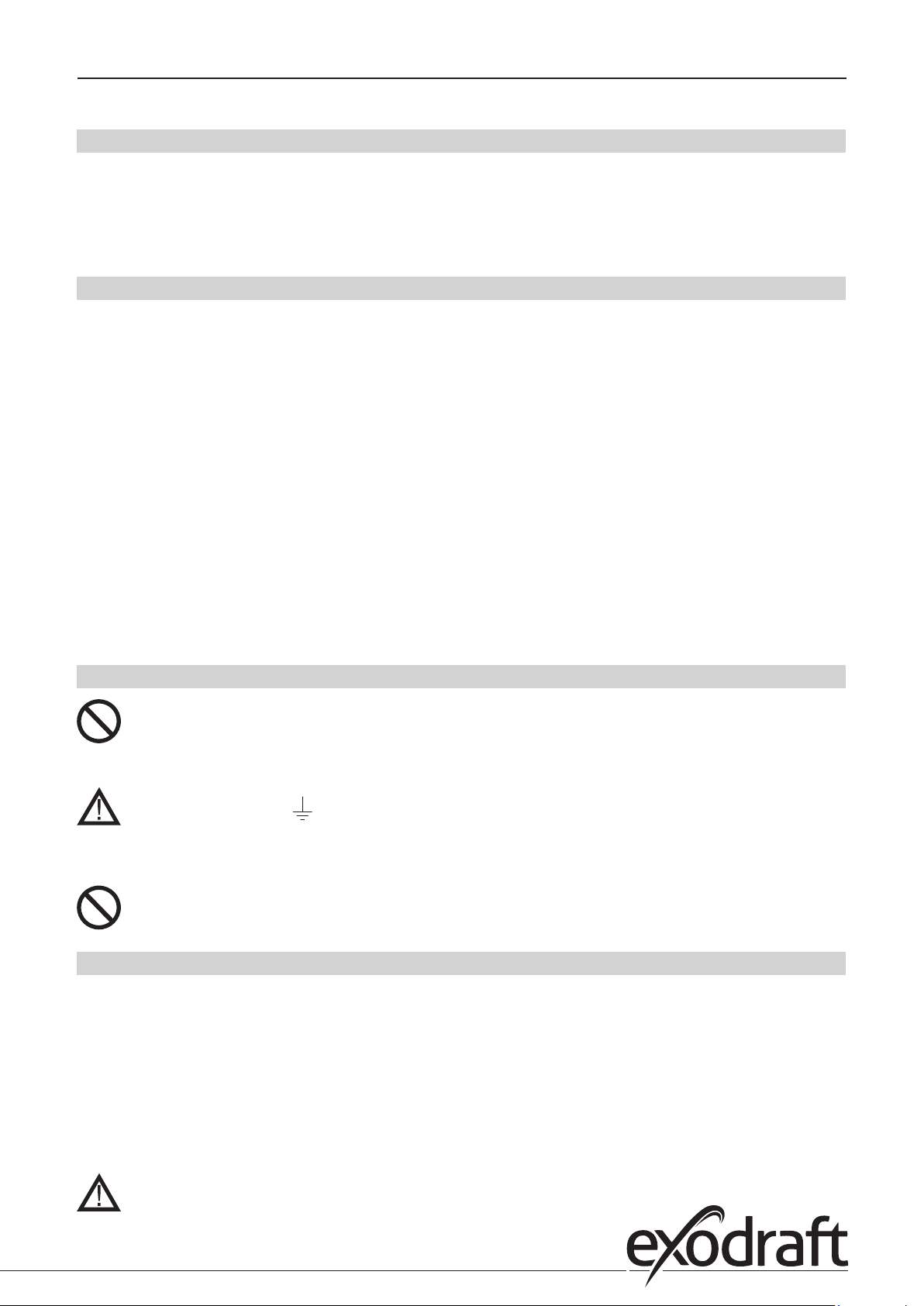
This example shows how to connect a voltage signal (18-230 V AC/DC) to EBC24 to start/stop the chimney fan.
• Connect the supply to terminals 1-3.
• Connecting the boiler:
• Connect the burner start signal (L) to terminal 12.
• Connect the neutral wire to terminal 13.
• The start signal for the burner is sent from terminal 15.
• Loop terminals 12 and 14.
• Connect the chimney fan to terminals 4-6.
• Connect the pressure transducer (XTP) to terminals 22-24 with a shielded cable, and connect the display to terminal 6
Page 21
3120073-UK EBC24
4.4.2 One boiler with potential free contact
Pressure control • 21
SUPPLY IN
L1 N N
FAN MOTOR
OUT
REG
VFD Out
NO
ALARM OUT BOILER
C
NC
NO
BURNER
BOILER
1 - IN
1 - OUT
C
+/~
-/~
NO
C
2 - IN
+/~
-/~
BURNER
2 - OUT
NO
24 VDC
C
0V
PDS BUZZER
24VNCNO
VFD
0V
0V
0-10V
C
24V
XTP RS485
24V
0-10V0VA
NO
B
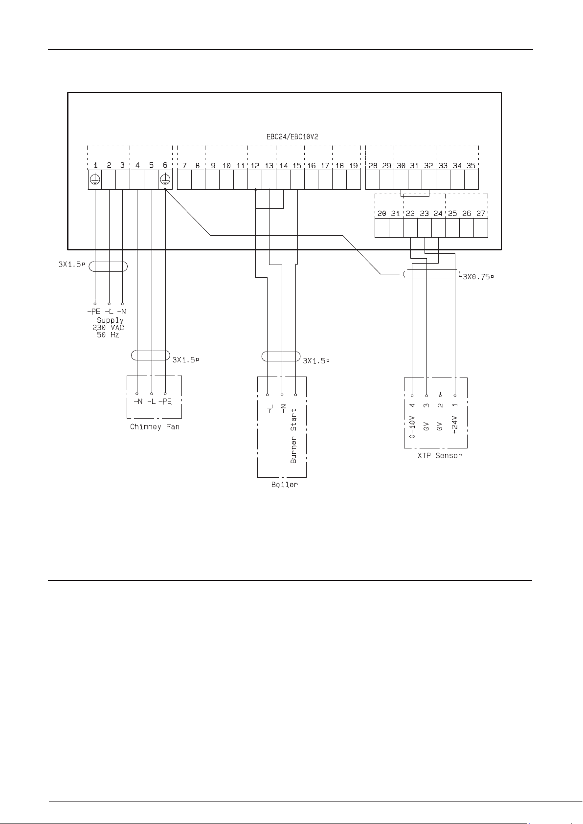
This example shows how to connect a potential free contact to the EBC24 to start/stop the fan:
• Connect the supply voltage to terminals 1-3.
• Connection to the boiler:
• Connect the potential free contact to terminals 12 & 29.
• Loop terminals 13 & 28.
• Connect the burner start signal to terminals 14 & 15.
• Connect the chimney fan to terminals 4-6.
• Connect the pressure transducer (XTP) to terminals 22-24 with a shielded cable, and connect the display to terminal 6.
Page 22
1 2 3 4 5 6 7 8
SUPPLY IN
VFD Out
L1 N N
FAN MOTOR
OUT
REG
NOCNCNOC
+/~
-/~
+/~
-/~
NO
C
ALARM OUT BOILER
1 - IN
BURNER
1 - OUT
BOILER
2 - IN
BURNER
2 - OUT
C
NO
24 VDC
0V
24VNCNOC24V
NO
PDS BUZZER
VFD
0V
0-10V
0V
24V
0-10V0VA
B
XTP RS485
22 • Pressure control
4.4.3 One boiler and extra monitoring with PDS
3120073-UK EBC24
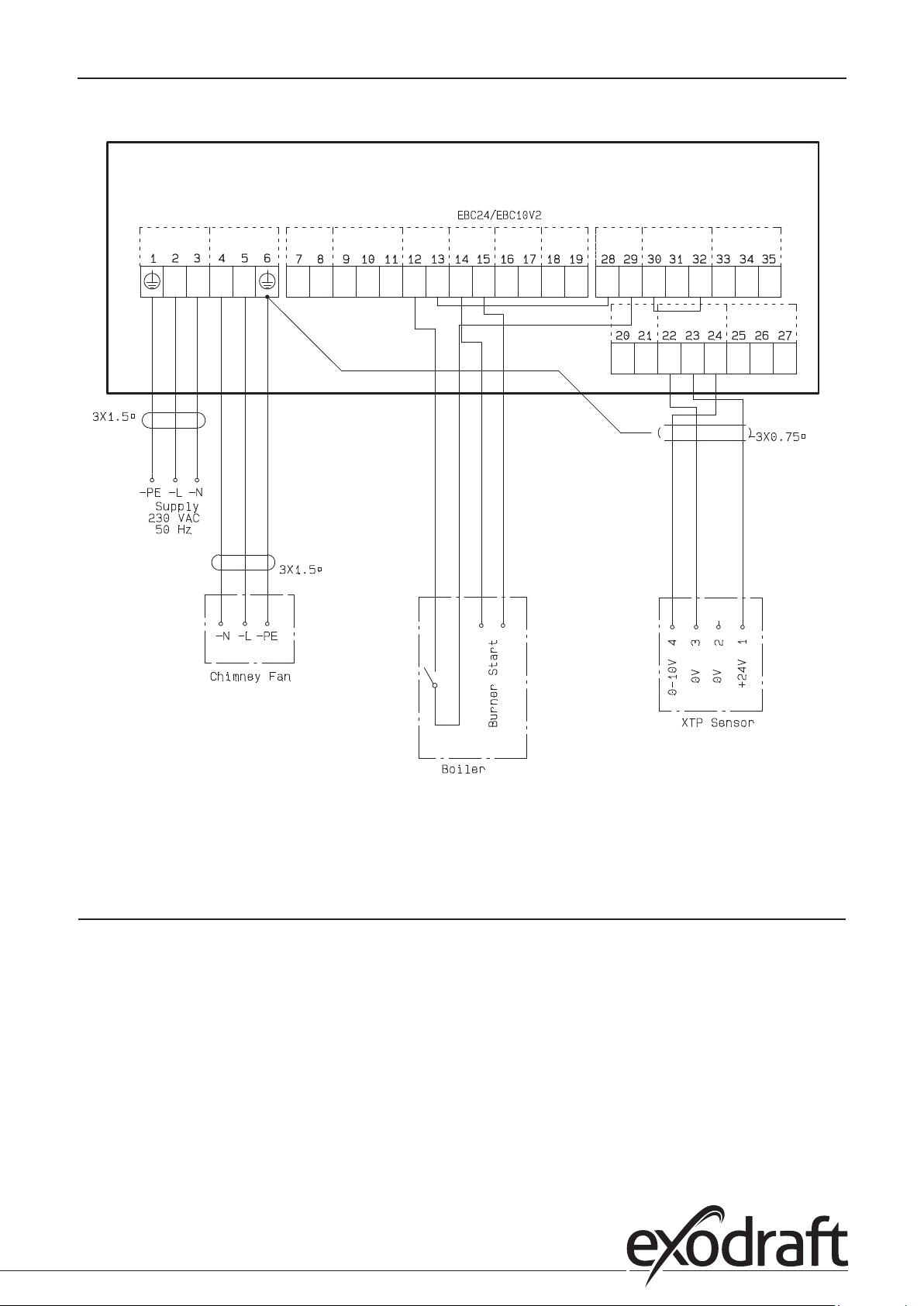
This example shows how to connect a PDS to EBC24. The PDS supplies extra monitoring
• Connecting PDS:
• Remove the factory installed wiring between terminals 30 and 32.
• Connect PDS to terminals 30, 31 and 32.
• Connect the supply to terminals 1-3.
• Connecting the boiler:
• Connect the potential free contact to terminals 12 & 29.
• Connect the burner start signal to terminals 14 & 15.
• Loop terminals 13 and 28.
• Connect the chimney fan to terminals 4-6.
• Connect the pressure transducer (XTP) to terminals 22-24 with a shielded cable, and connect the display to
terminal 6.
Page 23
1 2 3 4 5 6 7 8
3120073-UK EBC24
4.4.4 One boiler connected to frequency converter
Pressure control • 23
SUPPLY IN
L1 N N
FAN MOTOR
OUT
REG
VFD Out
NO
ALARM OUT BOILER
C
NC
NO
BURNER
BOILER
1 - IN
1 - OUT
C
+/~
-/~
NO
C
2 - IN
+/~
-/~
BURNER
2 - OUT
24 VDC
C
NO
0V
PDS BUZZER
24VNCNOC24V
0-10V
0V
XTP RS485
24V
VFD
0V
0-10V
NO
0V
A
B
This example shows which inputs/outputs on the EBC24 need to be connected to the frequency converter, when one
is used to control the chimney fan:
• Connect the supply to terminals 1-3.
• Frequency converter:
• Connect terminals 7 & 8 to the start/stop input on the frequency converter.
• Connect terminals 21 & 22 to the frequency converter input for external speed regulation.
• If needed, connect terminals 30 and 32 to the alarm output of the frequency converter (First removed
the factory installed jumper).
• Connect the pressure transducer (XTP) to terminals 22-24 with a shielded cable, and connect the display to terminal 6.
• Connecting the boiler:
• Connect the burner start signal (L) to terminal 12.
• Connect the neutral wire to terminal 13.
• The start signal for the burner is sent from terminal 15.
• Loop terminals 12 and 14
Page 24
24 • Pressure control
4.4.5 Two boilers with continuous operation of chimney fan
3120073-UK EBC24
SUPPLY IN
L1 N N
FAN MOTOR
OUT
REG
VFD Out
NO
ALARM OUT BOILER
C
NC
NO
BURNER
BOILER
1 - IN
C
1 - OUT
+/~
-/~
NO
C
2 - IN
+/~
-/~
BURNER
2 - OUT
NO
24 VDC
C
0V
PDS BUZZER
24VNCNO
VFD
0V
0-10V
C
24V
XTP RS485
0V
24V
0-10V0VA
NO
B
This example shows how to connect the EBC24 if you require continuous operation of the chimney fan:
• Connect the supply to terminals 1-3.
• Loop terminals 13 & 17 & 28.
• Loop terminals 12 & 16 & 29.
• Connecting the boiler (example with two boilers):
• Connect boiler 1 burner start signal to terminals 14 & 15.
• Connect boiler 2 burner start signal to terminals 18 & 19.
• Connect the chimney fan to terminals 4-6.
• Connect the pressure transducer (XTP) to terminals 22-24 with a shielded cable, and connect the display to terminal 6.
Page 25
3120073-UK EBC24
Pressure-controlled regulation • 25
5. Pressure regulation of supply air fan
5.1 Application
General
• The EBC24 is used to control a supply air fan.
• EBC an control a supply air fan directly or indirectly via a frequency converter.
Positioning
24 cInstall the EBC24 and the pressure transducer (XTP) in the boiler room as described in section 2.2 Fitting, pages 6+7
5.2 Mode of operation
General function
• The EBC24 monitors the pressure in the boiler room and disconnects the burner in the event of errors (the
alarm diode on the EBC24 will turn on).
• When the pressure in the boiler room changes, the EBC24 will change the fan speed in order to meet the
set point pressure for the boiler room.
• The EBC24 is connected to the boiler system in such a way that when a heating requirement arises, the
EBC24 will start the fan, delaying the start of the boilers until the pressure in the boiler room is adequate.
• A safety function ensures that if the pressure in the boiler room is insucient, the EBC22 will shut down
the boilers the EBC24 will shut down the boilers, should the pressure in the boiler room become insucient.
5.3 Electrical connection
This work must be performed by a qualied electrician in accordance with locally applicable rules and
legislation.
Installation of the supply cable must comply with applicable legislation and regulations.
The grounding terminal ( ) must always be connected.
When connecting a pressure transducer (XTP) and frequency converter, shielded cable must be used.
Isolation switch
exodraft a/s stresses that according to EU’s Machinery Directive, an isolation switch must be
incorporated into the xed installation.
The isolation switch is not supplied by exodraft, but is available as an accessory.
5.4 Wiring examples
This example shows how to connect the EBC24 to a frequency converter/MPR-relay.
exodraft recommends contacting the boiler manufacturer for correct connection to the boiler
automation.
Page 26
26 • Pressure-controlled regulation
5.4.1 Connection of frequency converter/MPR-relay
3120073-UK EBC24
SUPPLY IN
L1 N N
FAN MOTOR
OUT
REG
VFD Out
ALARM OUT BOILER
NOCNCNOC
1 - IN
+/~
-/~
BURNER
1 - OUT
NO
C
BOILER
2 - IN
+/~
-/~
BURNER
2 - OUT
NO
24 VDC
C
0V
PDS BUZZER
24VNCNOC24V
0-10V
0V
XTP RS485
24V
VFD
0V
0-10V0VA
NO
B
This example shows which inputs/outputs on the EBC24 need to be connected to the frequency converter/MPR-relay.
• Connect the supply to terminals 1-3.
• Loop terminals 13 & 28.
• Connecting the boiler:
• Connect the burner start signal to terminals 14 & 15.
• Connect the potential free contact to terminals 12 & 29.
• Frequency converter
• Connect terminals 7 & 8 to the start/stop input on the frequency converter.
• Connect terminals 20 & 21 input for external speed regulation.
• If needed, connect terminals 30 and 32 to the alarm output of the frequency converter.
• Connect the pressure transducer (XTP) to terminals 22-24 with a shielded cable, and connect the display to terminal 6
Page 27
3120073-UK EBC24
6. EU Declaration of Conformity
Declaration of Conformity
EU declaration of conformity • 27
DK: EU-Overensstemmelseserklæring
GB: Declaration of Conformity
DE: EU-Konformitätserklärung
FR: Déclaration de conformité de l’Union Européenne
NO: EU-Samsvarserklæring
exodraft a/s
C.F. Tietgens Boulevard 41
DK-5220 Odense SØ
-erklærer på eget ansvar, at følgende produkter:
-hereby declares that the following products:
-erklärt hierdurch auf eigene Verantwortung, daß folgende Produkte:
-déclare, sous sa propre responsabilité, que les produits suivants:
-erklærer på eget ansvar at følgende produkter:
-som er omfattet af denne erklæring, er i overensstemmelse med
følgende standarder:
-were manufactured in conformity with the provisions of the following
standards:
-die von dieser Erklärung umfaßt sind, den folgenden Normen:
-auxquels s’applique cette déclaration sont en conformité avec les
normes ci-contre:
-som er omfattet av denne erklæring, er i samsvar med følgende standarder:
EN 60335-1, EN60335-2-102, EN 61000-6-1, EN 61000-6-2, EN 61000-6-3, EN 14459:2008
-i.h.t bestemmelser i direktiv:
-in accordance with
-entsprechen gemäß den Bestimmungen der folgenden Richtlinien:
-suivant les dispositions prévues aux directives:
-i.h.t bestemmelser i direktiv:
-Lavspændingsdirektiv:
-the Low Voltage Directive:
-Niederspannungsrichtlinie:
-Directive Basse Tension:
-Lavspenningsdirektivet:
2014/35/EC
-EMC-direktivet:
-and the EMC Directive:
-EMV-Richtlinie:
-Directive Compatibilité Electromagnétique:
-EMC-direktivet:
2014/30/EC
Odense, 03.04.2017
-Adm. direktør
-Managing Director
Jørgen Andersen
NL: EU-Conformiteits verklaring
SE: EU-Överensstämmelsedeklaration
FI: EU-Vaatimustenmukaisuusvakuutus
IS: ESS-Samræmisstaðfesting
IT: Dichiarazione di Conformità Unione Europea
-veklaart dat onderstaande producten:
-deklarerar på eget ansvar, att följande produkter:
-vastaa siltä, että seuraava tuote:
-Staðfesti à eigin àbyrgð, að eftirfarandi vörur:
-dichiara con la presente che i seguenti prodotti:
EBC24
-zijn vervaardigd in overeenstemming met de voorschriften uit de
hieronder genoemde normen en standaards:
-som omfattas av denna deklaration, överensstämmer med följande
standarder:
-jota tämä selvitys koskee, on seuraavien standardien mukainen:
-sem eru meðtalin i staðfestingu Pessari, eru i fullu samræmi við
eftirtalda staðla:
-sono stati fabbricati in conformità con le norme degli standard
seguenti:
-en voldoen aan de volgende richtlijnen:
-enligt bestämmelserna i följande direktiv:
-seuraavien direktiivien määräysten mukaan:
-med tilvisun til àkvarðana eftirlits:
-in conformità con le direttive:
-de laagspanningsrichtlijn:
-Lågspänningsdirektivet:
-Pienjännitedirektiivi:
-Smáspennueftirlitið:
-Direttiva Basso Voltaggio:
-en de EMC richtlijn:
-EMC-direktivet:
-EMC-direktiivi:
-EMC-eftirlitið:
-Direttiva Compatibilità Elettromagnetica:
-Algemeen directeur
-Geschäftsführender Direktor
-Président Directeur Général
-Verkställande direktör
-Toimitusjohtaja
-Framkvemdastjori
-Direttore Generale
Page 28

DK: exodraft a/s
C. F. Tietgens Boulevard 41
DK-5220 Odense SØ
Tel: +45 7010 2234
Fax: +45 7010 2235
[email protected]
www.exodraft.dk
SE: exodraft a/s
Kasten Rönnowsgatan 3B 4tr
SE-302 94 Halmstad
Tlf: +46 (0)8-5000 1520
[email protected]
www.exodraft.se
NO: exodraft a/s
Storgaten 88
NO-3060 Svelvik
Tel: +47 3329 7062
[email protected]
www.exodraft.no
UK: exodraft Ltd.
10 Crestway, Tarleton
GB-Preston PR4 6BE
Tel: +44 (0)1494 465 166
Fax: +44 (0)1494 465 163
[email protected]
www.exodraft.co.uk
DE: exodraft GmbH
Soonwaldstraße 6
DE-55569 Monzingen
Tel: +49 (0)6751 855 599-0
Fax: +49 (0)6751 855 599-9
[email protected]
www.exodraft.de
3002712 EBC20 DK 080816
 Loading...