

3120065 EBC24 US 20170329
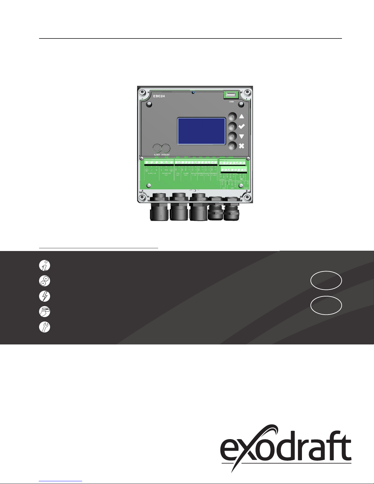
EBC24 modulating fan control
Installation and operation manual
READ AND SAVE THESE INSTRUCTIONS!
Product information Chapters 1 + 2
Mechanical installation Chapter 3
Electrical installation Chapter 4
Start up and conguration Chapter 5
Maintenance and troubleshooting Chapter 6
Job name: _____________________________________
Installer: ______________________________________
Installation date: _______________________________
USA
CAN
Distributor contact information:
ENERVEX Inc. • T: 800.255.2923
info@enervex.com • www.enervex.com
Contents
2
3120065 EBC24 US 20170329
1. Product information
1.1 Function ........................................................................3
1.2 Shipping ........................................................................3
1.3 Warranty ........................................................................3
2. Specications
2.1 Dimensions and capacities ......................................................4
3. Mechanical installation
3.1 Location ........................................................................5
3.2 Mounting of control ............................................................5
3.3 Mounting of transducer .........................................................6
3.4 Mounting of stack probe ........................................................6
3.5 Connecting transducer to stack probe ...........................................6
4. Electrical installation
4.1 General .........................................................................7
4.2 Continuous chimney fan operation ..............................................8
4.3 Intermittent chimney fan operation (120 V) ......................................9
4.4 Connection to a variable frequency drive .......................................11
4.5 Integrated Proven Draft Switch with external Proven Draft Switch backup ........12
5. Startup and conguration
5.1 General ........................................................................13
5.5 Basic control set-up ............................................................13
5.6 Detailed control programming .................................................14
6. Settings and troubleshooting
6.1 Troubleshooting ...............................................................15
6.2 Settings ........................................................................16
Symbol legend
The following terms are used throughout this manual to bring attention to the presence of potential hazards
or to important information concerning the product.
DANGER
Indicates an imminent hazardous situation which,
if not avoided, will result in death, serious injury or
substantial property damage.
CAUTION
Indicates an imminent hazardous situation which, if
not avoided, may result in personal injury or property
damage.
TO REDUCE THE RISK OF FIRE, ELECTRICAL SHOCK OR INJURY TO PERSONS,
OBSERVE THE FOLLOWING:
1. Use this unit in the manner intended by the manufacturer. If
you have questions, contact the manufacturer’s distributor at the
address or telephone number listed on the front of the manual.
2. Before servicing or cleaning the unit, switch o at service panel
and lock service panel to prevent power from being switched on
accidentally.
3. Installation work and electrical wiring must be done by a qualied person(s) in accordance with applicable codes and standards.
Association (NFPA), and the American Society for Heating, Refrigeration and Air Conditioning Engineers (ASHRAE), and the local
code authorities.
5. This unit must be grounded.
How to use this manual
This installation manual does not contain any system design
documentation. System design documentation is available from
ENERVEX.
4. Follow the appliance manufacturer’s guidelines and safety
standards such as those published by the National Fire Protection
Accessories and variable frequency drives are not covered by this
manual. Please refer to these component’s individual manuals.

3120065 EBC24 US 20170329
1. Product information
1.1 Function
Use The exodraft EBC24 is a Modulating Fan Control used with up to two appliances to monitor and
maintain a constant draft or pressure in a chimney or duct. This is achieved by modulating the speed
of a chimney fan or ventilator. The EBC24 can be used with models RSV, BESF and BESB. It can control
the fan speed directly or via a Variable Frequency Drive (VFD).
The EBC24 is typically used to control the draft in systems requiring a single boiler or water heater.
Function The control monitors the draft in a chimney system via connection to a pressure sensor (XTP) at-
tached to the chimney, and maintains it by modulating the fan speed. The control has an integrated
safety system that assures the heating appliance is shut down in case of fan failure or control failure.
The use of the EBC24 is not restricted to any type of fuel or type of heating appliance. When the appliance thermostat closes and calls for heat, the control will send maximum voltage to the chimney
fan or VFD. When the necessary draft is achieved, the control will allow boiler ring and regulate the
voltage to the fan or VFD, so the required draft is maintained (the value can be viewed in the display).
In case of insucient draft, the control will assure the burner will be shut down after 15 seconds (Can
be adjusted). When the appliance has satised the thermostat and shuts down, the control will turn
o the fan.
The control can be used in one of two ways:
• Interlocked with the appliance to pre-purge the chimney prior to boiler start-up and post-purge the
chimney for a variable time after boiler shut down.
• Set to run the fan continuously.
3
Other functions The control has an integrated safety function. It can be operated with either a manual reset function
(reset button) or an automatic reset function. All terminal connections are monitored by LED’s for
easy service and troubleshooting.
Listings EBC24 is UL listed to the Standard for Industrial Control Equipment, UL60947-4-1 and CSA C22.2 No.
14-10.
1.2 Shipping
The EBC24 standard packing list
y EBC24 control unit
y Pressure transducer (XTP)
y Silicone tubing
y Stack probe
If other components are shipped, these will appear as separate items on the shipment packing list.
1.3 Warranty
Complete warranty conditions are available from ENERVEX, Inc.
B
A
C
D
F
G
E
H
1.45
2.90 3.33
1.89
1.32
.37
POWER
HI LO
SPAN
ZERO
.56
3120065 EBC24 US 20170329
2. Specications
4
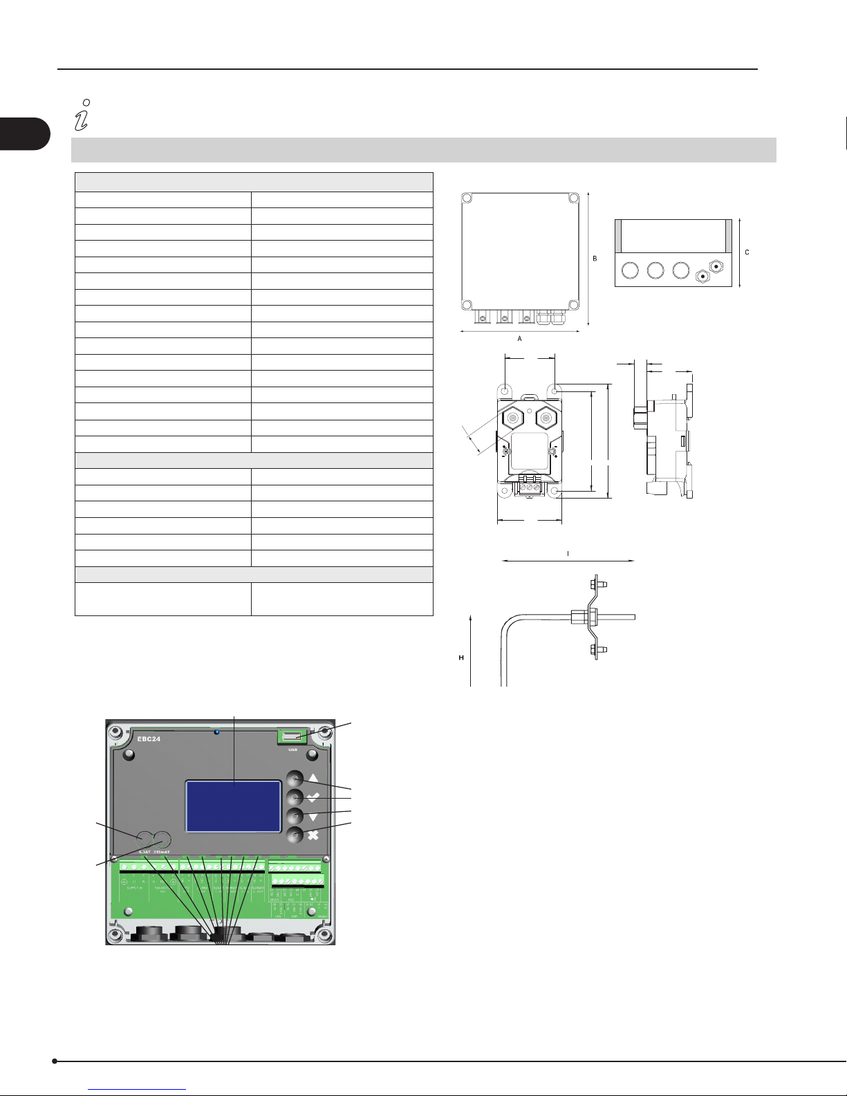
2.1 Dimensions and capacities
exodraft EBC24 Control
Power supply V 1x120 VAC / 60 Hz
Fuse size Control/Motor A 0.4T/6.3T /250V(JDYX2/8)
Max. Motor load kW/hp 0.35/0.5
Operating temperature °F/°C -4 to 122/-20 to 50
Range of operation inWC/Pa 0-0.6/0-150
Tolerance inWC/Pa 0.01/3+/-10%
+24V Supply mA 100 Max.
Control signal VFD VDC/mA 0-10 / Max. 10
Control and Alarm relay Max 120 VAC/4A AC1 - 24 VDC/2A DC1
Boiler Inputs 10-48 VDC / 10-132 VAC
VFD Relay Max 120 VAC/2A AC1 - 24VDC/2A DC1
Output TRIAC VAC 10-120
Dimensions AxBxC 6.9/175 x 6.9/175 x 4.33/110 in/mm
Weight lbs/kg 3.0/1.5
EMC standard UL 60947
IP-Rating NEMA 3R
Ashcroft XTP-sensor
Power supply VDC 14-36
Amperage mA 6
Output VDC 0-10
Operating temperature °F/°C 0 to 160/-17 to 70
Tolerance inWC/Pa 0.01/3+/-10%
Weight lbs/kg .9/.4
Chimney Probe
Dimensions H in/mm 4.25/108
I in/mm 3.50/89
EBC24
Fig. 1
Symbols
Fig. 1-A Fuse holder Exhaust Fan
Fig. 1-B Fuse holder Control
Fig. 1-C Display 128 x 64 pixels
Fig. 1-D USB port
Fig. 1-E Up button
Fig. 1-F Select / Conrm button
Fig. 1-G Down button
Fig. 1-H Reset / Back button
Fig. 1-I LEDs (green) showing ON/OFF status
3120065 EBC24 US 20170329
3. Mechanical installation
3.1 Location
The control and the transducer must be installed inside, preferably in the boiler room. The control does not need to be
installed in an enclosure. Fig. 2 shows how the components are connected.
EBC24 Control
Fig. 2aFig. 2
The transducer cannot be mounted inside an airtight enclosure. It uses the boiler room pressure/atmospheric pressure as reference pressure.
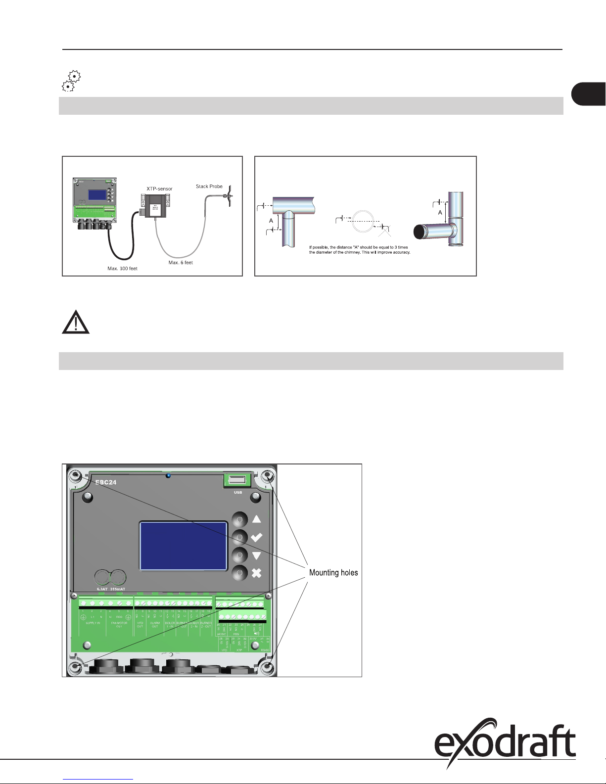
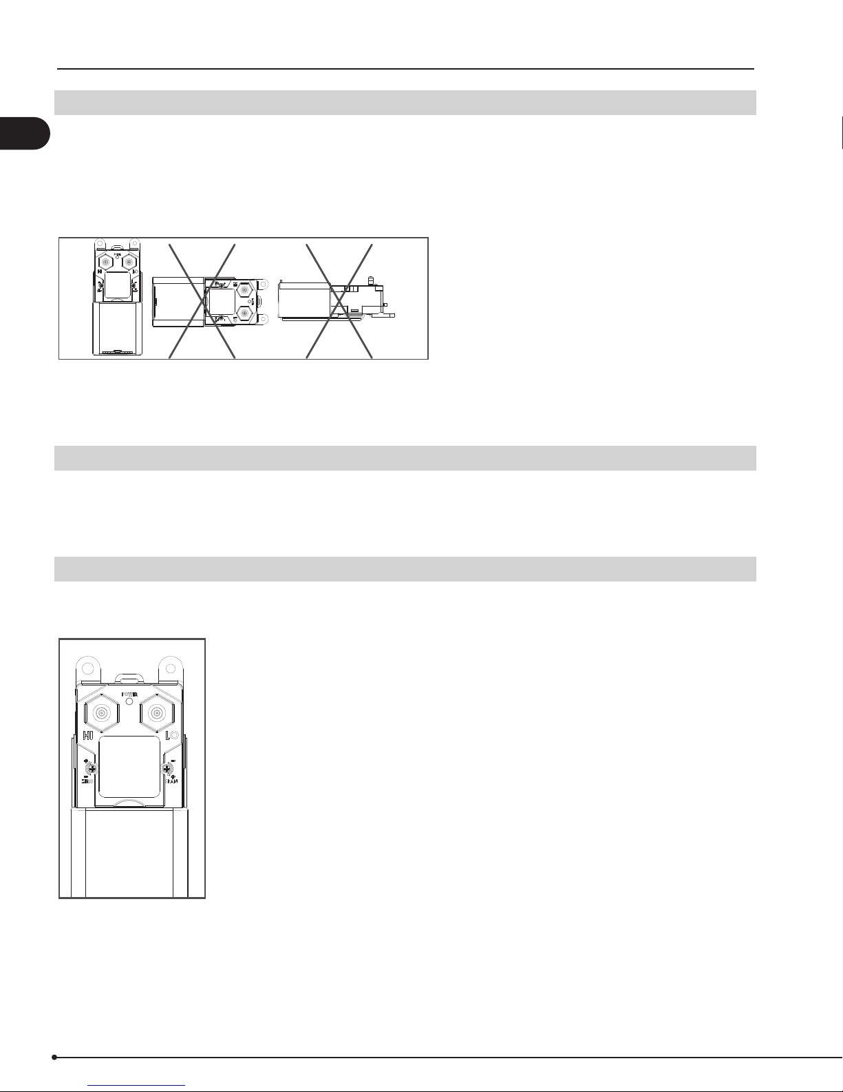
3.2 Mounting of control
5
The control can be mounted directly on a wall or similar.
y Remove the clear cover.
y The mounting holes are located under the plastic screws that hold the cover in place (Fig. 3).
y The distance between the control and the transducer should not exceed three hundred (300) feet.
Fig. 3
3120065 EBC24 US 20170329
3.3 Mounting of transducer
Attention must be paid to the position and location of the transducer. Fig. 5 shows the required position. Failure to follow
6
this instruction may result in an inoperable system.
y An Ashcroft XTP-sensor used for sensing draft should be mounted within six (6) feet of the stack probe.
y An Ashcroft XTP-sensor used for sensing room pressure should be mounted within fty (50) feet of the Outdoor
Pressure Probe.
Fig. 4
3.4 Mounting of stack probe
The probe (Fig. 2a on page 5) is inserted into the chimney or vent at the point where the draft should be kept constant.
This could be at the appliance outlet, in the vent or similar.
Referring to Fig. 2, make sure the tip of the tube is ush with the inner wall of the stack. Inserting it too far may aect the
reading and thereby the operation.
3.5 Connecting transducer to stack probe
The transducer is connected to the stack probe via a silicone tube. Make sure that the tube is connected to the proper
transducer port as shown in Fig. 5.
Fig. 5

3120065 EBC24 US 20170329
4. Electrical installation
4.1 General
DANGER
Turn o electrical power before servicing. Contact with live electric components can cause shock or death.
NOTE
EBC24 is designed for 1x120 VAC power supply only. Fan output is regulating on the phase side and
cannot be connected to other circuits.
The control can be used in two ways:
y Connected so the fan runs continuously independent of appliance operation (see paragraph 4.2).
y Interlocked with an appliance so the appliance operation indirectly controls the fan operation (see paragraph 4.3).
In both cases the control will still monitor and maintain a constant draft.
There are two types of safety systems available:
y Integrated Proven Draft Switch (standard)
y Integrated Proven Draft Switch with external Proven Draft Switch (accessory) backup
(see paragraph 4.4).
7
The terminals are connected as shown on g. 6:
Terminal Use
1 Power Supply-PE Ground
2 Power Supply-L1
3 Power Supply-N
4 Chimney Fan-N
5 Chimney Fan-L1 (Regulating)
6 Chimney Fan-PE Ground
7 VFD Relay NO
8 VFD Relay C
9 Alarm Out-NC
10 Alarm Out-NO
11 Alarm Out-C
12 Voltage Input from Appliance / Boiler 1 thermostat
Optocoupler (+) (10-120 VAC/DC)
13 Voltage Input from Appliance/Boiler 1 thermostat
Optocoupler (-) (10-120 VAC/DC)
14 Burner 1 relay contact-Normally Open (max. 120 VAC, 4 Amps.)
15 Burner 1 relay contact-Common (max. 120 VAC, 4 Amps.)
16 Voltage Input from Appliance / Boiler 2 thermostat
Optocoupler (+) (10-120 VAC/DC)
17 Voltage Input from Appliance / Boiler2 thermostat
Optocoupler (-) (10-120 VAC/DC)
Terminal Use
18 Burner 2 relay contact-Normally Open (max. 120 VAC, 4 Amps.)
19 Burner 2 relay contact-Common (max. 120 VAC, 4 Amps.)
20 Control signal VFD 0 VDC
21 Control signal VFD 0-10 VDC
22 XTP-0 VDC Power Supply (transducer)
23 XTP-24 VDC Power Supply (transducer)
24 XTP-0-10 VDC Return Signal (transducer)
25 RS485 0V
26 RS485 A
27 RS485 B
28 0VDC Power Supply
29 24 VDC Power Supply (Max 100 mA)
30 PDS-NC (Normally Closed) Proven Draft Switch
31 PDS-NO (Normally Open) Proven Draft Switch
32 PDS-C (Common) Proven Draft Switch
33 Buzzer-24 VDC Supply
34 Not used
35 Buzzer Signal
Fig. 6

4.2 Continuous chimney fan operation
XTP2
COM Vout Vin
Fig. 7 shows how to connect a chimney fan to the EBC24 if continuous operation is needed:
8
y Connect the power supply to terminals 1, 2 and 3.
y Jump terminals 13 and 28.
y Jump terminals 12 and 29
y Jump terminals 30 and 32
y Connection to the appliance(s):
Connect the start signal from the burner to terminals 14 and 15.
y To connect the chimney fan:
If using a 1x120V chimney fan, connect it to terminals 4, 5 and 6. Refer to the fan’s Installation Manual.
If using a 3-phase fan and VFD, connect the VFD to terminals 20 and 21 as shown in Fig. 10 and 11.
DO NOT connect the fan directly to the EBC24 control.
y Connect the XTP transducer to terminals 22, 23 and 24.
3120065 EBC24 US 20170329
Fig. 7

XTP2
COM Vout Vin
3120065 EBC24 US 20170329
4.3 Intermittent chimney fan operation (120 V)
The control can be interlocked with an appliance in two ways:
It can be interlocked directly with an appliance control, or with a dry set of contacts.
Interlock with Burner
Figure 8 shows how an appliance control signal (10-120V AC/DC) is connected to the EBC24:
y Connect the power supply to terminals 1, 2 and 3.
y Connection to the appliance:
Connect the boiler start signal to terminals 12 and 13
The start signal to the burner is now activated by terminal 14.
Connect Neutral to terminal 15.
y To connect the chimney fan:
If using a 1x120V chimney fan, connect it to terminals 4, 5 and 6. Refer to the fan’s Installation manual.
If using a 3-phase fan and VFD, connect the VFD to terminals 20 and 21 as shown in Fig. 10 and 11.
DO NOT connect the fan directly to the EBC24 control.
y The XTP-transducer is connected to terminals 22, 23 and 24.
9
Fig. 8

Interlock with dry set of contacts
Figure 9 shows how a dry set of contacts is connected to the EBC24:
10
y Connect the power supply to terminals 1, 2 and 3.
y Connection to the appliance:
Connect the dry set of contacts to terminals 12 and 13.
Connect the start signal to the burner to terminals 14 and 15.
y To connect the chimney fan:
If using a 1x120V chimney fan, connect it to terminals 4, 5 and 6. Refer to the fan’s Installation Manual.
If using a 3-phase fan and VFD, connect the VFD to terminals 20 and 21 as shown in Fig. 10 and 11. DO NOT con-
nect the fan directly to the EBC24 control.
Connect the XTP transducer to terminals 22, 23 and 24
3120065 EBC24 US 20170329
Fig. 9
COM Vout Vin
XTP2

3120065 EBC24 US 20170329
4.4 Connection to a variable frequency drive
To connect the 3-phase fan and variable frequency drive (VFD), connect the VFD to terminals 20 and 21 of the EBC24.
DO NOT connect the fan directly to the control.
Wire the ABB ACS355 series variable frequency drive according to g. 10.
Fig. 10
Wire the Enervex E-Drive variable frequency drive according to g. 11.
11
Fig. 11

EBC24 Control board
3120065 EBC24 US 20170329
4.5 Integrated Proven Draft Switch with external Proven Draft Switch backup
Fig. 12 shows how to connect a external Proven Draft Switch (PDS) to the EBC24.
12
The external PDS is a backup to the integrated PDS and both must be satised by sucient draft to release the appliance:
y Remove the factory installed jumper over terminals 30 and 32.
y Connect the switch to terminals 30, 31 and 32 as shown on g. 12.
Fig. 12

3120065 EBC24 US 20170329
5. Startup and conguration
5.1 General
When power is supplied to the control it will go through a start-up procedure to detect and check all components and
appliances installed.
5.5 Basic control set-up
Once power is turned ON the control can be programmed. Most parameters are programmed at the factory and do not
need to be changed. The most common parameters are shown below.
To enter the setup menu, press the “” key for more than 5 seconds. The password 3142 must be entered using the up and
down buttons, and after that press the “” key.
Menu 11: SET EXHAUST
For setting the draft or exhaust pressure. Although the value, when measured in the eld, is negative pressure it shows up
as a positive value on the display. The lowest possible value is 0.012 inWC. Most applications require a setting in the range
of 0.012 inWC to 0.100 inWC. Atmospheric appliances (Category I) are always in the low range, while all other appliances
can be anywhere.
The %-value indicates the relative setting of the total range of the sensor. (The [inWC] units can be changed to [Pa] in the
menu 512. )
13
Menu 12: EXHAUST OPERATING MODE
The control can operate the fan(s) in either ‘continuous’ or ‘intermittent’ mode. The mode can be changed via the display in
menu 12.
Note! Continuous mode only works if Priority mode is “o” (menu 451)
In ‘continuous’ mode the fan operates continuously. During times when the heating appliance(s) is not operating, the fan
will still operate although at its lowest capacity. Some exhaust will be pulled through the appliance. The chimney is always
primed and there is no real need for pre- and post-purge functions. The energy consumption in this mode is minimal.
In ‘intermittent’ mode the fan only operates if at least one appliance is operating. When no appliance(s) is operating the
fan shuts down. In this mode, pre- and post-purge functions are very important and must be set. This mode oers the lowest energy consumption.
If a heating system operates constantly, or the time between cycles is very short (less than 5-10 minutes), ‘continuous’
mode should be considered. Otherwise, ‘intermittent’ mode should be selected.
There is no need to set this value, if the control is used to control the supply of combustion air.
If used with a damper actuator, set for ‘continuous’ operation.
Menu 13: SET EXHAUST PRE-PURGE
When operating in ‘intermittent’ mode it is important to set the pre-purge. Pre-purge is the period from when there is a
call for heat until the control allows the appliance to start assuming the fan is operating at the proper capacity. The setting
can be anywhere from 0 to 1800 seconds.
There is no need to set this value, if the control is used to control the supply of combustion air.
Menu 14: SET EXHAUST POST-PURGE
When operating in ‘intermittent’ mode it is important to set the post-purge. Post-purge is the period from when the appliance shuts down until the control allows the fan to shut down assuming there are no more products of combustion in the
chimney system. The setting can be anywhere from 0 to 1800 seconds.
There is no need to set this value, if the control is used to control the supply of combustion air.

3120065 EBC24 US 20170329
14
5.6 Detailed control programming
Menu 362: USB logging
The EBC24 can be set to log on a USB-momory stick if the menu 362 is set to “USB” If this is done, two les will be created:
one with the alarm log and one with the values of the XTP sensors and 0-10V. The les are .CSV les.
The output format is:
[Unix time], [Exhaust XTP 0-1024], [Intake XTP 0-1024], [Exhaust VFD 0-1024], [Intake VFD 0-1024], [Damper Out 0-1024],
[MODS XTP 0-1024]. The value between 0-1024 is a fraction of 10V, meaning that a value of 423 equals 4.13 V.
Menu 365: Firmware upgrade
The EBC24 can be rmware upgraded using a USB-memory stick. Insert the USB-memory stick with the rmware in the
USB connector on the front of the control. Go to the 365 menu, and select the correct le to be programmed. Press the
abutton to start the update. The update takes approx. two minutes.
Note! If the programming fails, power o the control. Press the x button and power up the control again. Doing this will
reupload the latest working rmware.

3120065 EBC24 US 20170329
6. Settings and troubleshooting
6.1 Troubleshooting
Most terminal connections are monitored for proper operation. LED lights indicate operating status. If a light is lit, it indicates everything is functioning properly while a light out indicates a problem on the circuit it monitors. In addition, fault
codes are shown on the display.
The fault codes are:
Display Explanation
A1 Draft Exhaust Insucient draft pressure. Can be caused by:
1. Chimney fan does not have enough capacity
2. Mechanical or electrical fan failure
3. Blocked chimney
4. Introduction of excessive dilution air
5. XTP sensor not responding correctly
A2 Power Fault Indicates there has been a power fault
A3 XTP-Exhaust Indicates a disconnected signal from the XTP-Sensor on the exhaust side to the control Can be
A4 Error Start
A5 Alarm Override Indicates alarm has been ignored
A6 Draft Input Missing signal from PDS-function. Indicates a faulty function.
A7 RS485 error No communication between EBC31 and BACnet network
A8 Priority The draft has been insucient and therefore the control has gone into Priority mode
caused by:
1. Loose connections
2. Faulty XTP-sensor
3. Faulty controller
Indicates that the control has not been able to release the heating appliance(s) within 15 minutes.
15

3120065 EBC24 US 20170329
16
6.2 Settings
Menu Sub-menu function Display Description Range Default
1 Exhaust EXHAUST
11 Draft set point SET EXHAUST Adjustment of exhaust setpoint. 2%-95% af sensor 17%
12 Operation mode EXHAUST MODE Continuous or intermittent operation. In inter-
13 Pre-purge PRE-PURGE Pre-purge settings.
131 Time TIME Pre-purge time in seconds 0-1800 0
132 Operation mode SPEED MODE Select variable if the pre-purge should be con-
14 Post-purge POST-PURGE
141 Time TIME Post-purge settings. 0-1800 0
142 Operation mode SPEED MODE Select variable if the post-purge should be con-
15 Sensor SENSOR
151 Min. pressure RANGE MIN XTP minimum pressure in Pa. -500 – 500 Pa 0
152 Max. pressure RANGE MAX XTP Maximum pressure in Pa. 0 – 1000 Pa 150 Pa
16 Parameters PROPERTIES
161 Alarm limit draft ALARM LIMIT Select the alarm limit of the draft. The value is in
162 Alarmdelay ALARM DELAY Select a alarm delay from 0-120 seconds. 0 – 120 s 15
163 Min. voltage SPEED MIN Mimimum speed of the fan 0 – MENU 164 15 %
164 Max. voltage SPEED MAX Maksimum speed of the fan. MENU 163-100% 100
165 Xp EXHAUST Xp Proportional gain. 0-30 15
166 Ti EXHAUST Ti Integral gain. 0-30 8
mittent mode the exhaust fan runs only if one
or more boiler inputs are active.
trolled by the XTP-sensor or have a xed speed.
trolled by the XTP-sensor or have a xed speed.
% of the set point.
167 Sampling rate SAMPLING RATE Set the sampling rate for the PID Loop 1-10 10
168 Pressure type PRESSURE MODE Positive or negative pressure in the stack. Positive or Negative Negative
169 Application APPLICATION Sets if the control has to work as Exhaust
or Intake
2 ALARM
3 Service
21
22
23
31
32
321 BURNER I/O AUX OUT XXX
322 EXHAUST I/O EXH XTP x.xV OFF
323 Draft input DRAFT INPUT ON/
Alarm Status
Alarm log
Reset
Version no.
I/O
ERROR
ERROR LOG The last 10 alarms will be saved in the menu.
RESET Selecting "AUTO" will automatic reset the
SERVICE
VERSION Software version is showed.
I/O-VIEW
AUX IN XX
EXH VFD x.xV OFF
OFF
The error is shown here
alarm after 15 seconds. If "MAN" is selected,
the "X" has to be pressed.
In this menu the status of the boiler I/O is
shown. By pressing athe AUX OUT relays
can be activated by pressing up and down.
Multiple activations of the a button will move
from relay 1 to 6
XTP, VFD and VFD relay status for Exhaust.
Draft Input I/O status.
Continuous/
Intermittent
Variable / FIX 20-100% FIX 100%
Variable / FIX 20-100% Variable
If 167 = "Negative" ->50
- 80 %.
If 167 = "Positive" -> 150
- 300 %"
Exhaust / Intake Exhaust
MAN / AUTO AUTO
Intermittent
64 % (167 = "Negative")
144 % (167 = "Positive")
324 Alarm relay ALARM OUTPUT
ON/OFF
33 Options OPTION
331 Bearing cycle BEARING CYCLE Selecting "YES" will enable a bearing cycle on
332 Allow prime Selecting a number from 0-250 will enable the
333 Draft Input Delay DRAFT INPUT DELAY The delay before the control goes into Fraft
34 Factory reset FA CTORY If "YES" is selected, a factory reset will be
Alarm relay output status.
ON/OFF ON
present fans, if the boilers has not been active
for 24 hours.
0-250 s / o O
prime function. This allows the boilers to be
activated even though no sucient draft is
present.
0-20 s 0 s
Alarm
YES/NO NO
performed.

3120065 EBC24 US 20170329
Menu Sub-menu function Display Description Range Default
36 USB conguration USB CONFIG
361 format USB FORMAT USB Selecting "YES" will format the USB ash drive.
362 Data Log DATA LOG USB /
INTERNAL
363 Save cong. le SAVE CONFIG FILE Slecting "YES" provides the possibility to select
364 Load cong. le LOAD CONFIG FILE Selecting "YES" will download the current
365 Upgrade rmware UPGRADE FIRM-
WARE
4 User Interface USER INTERFACE
41 Display DISPLAY
411 Language LANGUAGE Language. ENG / FRA / ESP ENG
412 Pressure units UNITS Pa or inWC units. Pa / inWC inWC
413 LCD backlight LCD BACKLIGHT LCD backlight turned on or not. The USE param-
414 LCD contrast LCD CONTRAST 10 – 100 % 50
Notice! All data will erased!
Selecting "USB" will store the alarm log on the
USB ash drive, "INT" will store the log in the
internal memory.
congurationles stored on the USB ash drive.
conguration to the USB ash drive.
This function provides the possibility to
upgrade the rmware by means of a USB Stick
eter will cause the backligt to be turned on if a
button is pressed.
YES / NO NO
USB / INT INT
YES / NO NO
YES / NO NO
ON / OFF / USE ON
17

Distributor in USA & Canada
ENERVEX Inc.
1685 Bluegrass Lake Parkway
Alpharetta
GA 30004
P: 770.587.3238
F: 770.587.4731
T: 800.255.2923
info@enervex.com
www.enervex.com
www.exodraft.com
 Loading...