

Page 1
EX N’ FLEX
EX N’ FLEX
EF-250
EF-250
Instructions for Use
Model EF-250
Leg Exerciser
Page 2
Introduction
EX N’ FLEX Model EF-250 has been designed for people who have a wide range of walking problems from
the result of illness or accident. It provides a sustained, predictable Range of Motion to Muscles, Joints and
Tendons for individuals who face a future with little or no movement. The movement provided is both
physically and psychologically beneficial and may be used as an adjunct to regular physiotherapy or where
physiotherapy is not available.
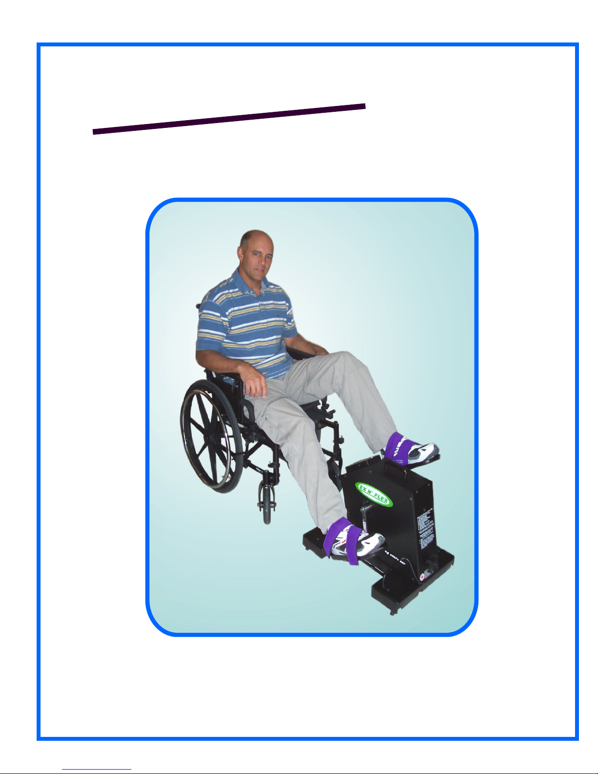
Understanding and Deploying the Locking Mechanism
Locking Lever
1.
Base Handle Position #1a & #1b
Position #1a; the Base Handle (Locking Mechanism) stands up
in a vertical position away from the top of the base and the wheels
are touching the floor. The machine can be freely moved or
transported.
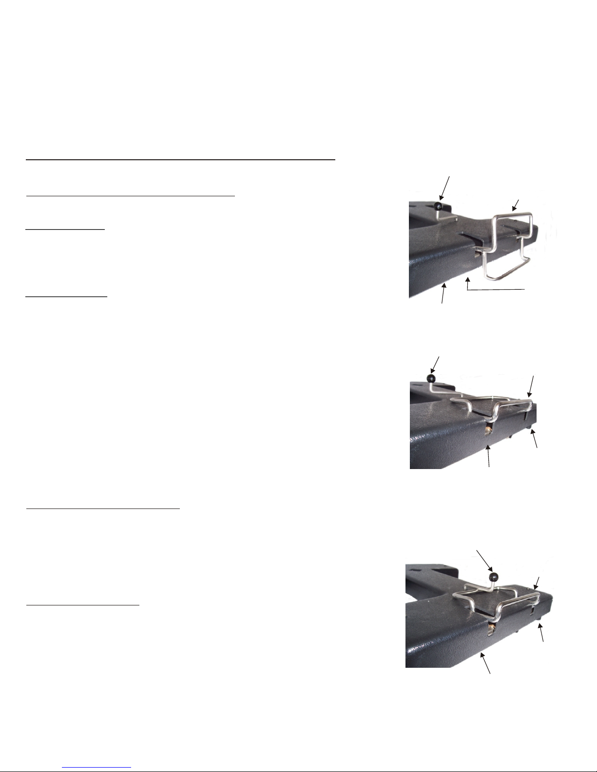
Position #1b; the has been pushed forward up
onto the base by gripping the lower part of the closest
to the floor. Once in place it should lay flat on the top of the base.
This lowers the rubber tipped legs and the wheels are now
suspended off the floor under the base cover.
Adjustment to the user's wheelchair or the machine may be
necessary to attain the best positioning. See P.4 (#1-5) for
positioning.
*** Try placing yourself in the machine initially. *** This
experiment will permit you to judge a more accurate placement
for each individual. There should be some bend in the knee
when the Foot Rests reach the furthest point of extension.
Base Handle
Base Handle
Base Frame
Position #1a
Locking Lever
Base Frame
Base Handle
4 Wheels
Located
under Base
Base Handle
4 Rubber
Stoppers
Base Handle Position #2
Once the is in position on top of the Base Cover, Base Handle
swing the Locking Lever over the top of the . The Base Handle
machine is now locked into position.
Unlock Mechanism:
To return the base to its wheels; grip the black locking lever knob
and swing the lever off and away from the . The
Base Handle
(locking mechanism), can now be pulled down
towards the floor raising the legs and allowing the wheels to
touch the floor.
Base Handle
Position #1b
Locking Lever
Base
Handle
4 Rubber
Stoppers
Base Frame
Position #2
Page 3

Operating Instructions
Understanding the Control Unit
The Control Unit contains all of the electronics, switches and displays necessary to control the operation
of the EX N’ FLEX EF-250 Leg Exerciser. It is secured to the Exerciser by means of two screws and plugs
into a connector. It can be easily removed for servicing or replacement..
* Plug the Power Cord into a 110/220 V.A.C. Wall outlet. PLEASE NOTE: Before attaching yourself
or anyone to the machine, it is recommended that you read these instructions thoroughly and
operate the Control Unit to familiarize yourself with the switching.*
The Main Power Switch:
The Main Power Switch is the black switch located on the right hand edge of the Control Box. When the
switch is turned on the Control Unit will light up. The Power Light comes on, zeros appear in the large LED
Display window and lights appear in the side windows by the Mode Switch, Speed Switch and the
F/Off/Rswitch. (Forward, Off. Reverse).
The Pressure Switches:
There are six different Pressure Switches on the Control Unit: On/Off, a direction switch(F/Off/R), Mode
Switch, Speed Switch and two Timer adjustment arrows.
2.
When the side mounted Main Power Switch is on, you can start the machine by selecting forward or
reverse. You can stop the machine by pressing the F/Off/R switch once to move the switch to the
centre/Off position or you can also turn it off by pressing the On/Off switch on the bottom left of the face of
the Control Unit, near the Power Light. If you turn it off here you will resume movement in the same
direction the machine was turning when it was stopped.
Try this now: Turn on the Main Power Switch located on the right hand edge of Control Box. Press the
F/Off/R Switch. The Foot Rests should begin to turn in Forward or Reverse depending on your selection.
Leave the machine running then try the Speed Switch.
The Speed Switch:
The Speed Switch contains three indicator lights: Hi, Med and Lo. To choose a speed, press the switch to
change between Lo, Med and Hi.
Now turn the machine off by pressing the On/Off switch on the face of the Control Unit.
Understanding the Mode Switch:
The Mode switch has four positions; Timer, Biof or Biofeedback, Trip and Tot al . A red indicator light
shows the mode being used.
When the machine is first turned on the Mode Switch default position is Biof. The function of the
Biofeedback display is explained further on.
The Timer Switch
Press the Mode Switch once and it will change to “Time” mode. Wh en in “Time” mode you can adjust/set
the timer by pressing the up and down arrows. These switches are located just below the LED digital
readout window. Increase the amount of time in 5 minute increments each time you press the”up” arrow.
Decrease the amount of time by 1 minute, each time you press the “down” arrow. You can view the
amount of time selected in the LED display window located above the arrows. When the machine is
turned on the timer will begin counting down in seconds and once it reaches zero the machine will
automatically shot off and the F/Off/R switch will have moved to the centre Off position.
Note: Once the timer is set you can switch between modes and the timer will still continue to count down.
Page 4

3
Odometer “Total” Switch:
While still in Time mode, press the Mode Switch 3 times and you will change the mode ( the red indicator
light will move) to “Total” “Total” display acts as an odometer and logs the distance travelled. The total
cannot be reset and continually accumulates (mileage/kilometers for leg units).
Odometer “Trip” Switch:
Press the Mode Switch again and the red light will change the mode to “Trip”. “Trip” mode logs in meters
or yards in the U.S.A. the distance travelled for each session. Every Trip count, equals 1 meter. Every
1000 meters logged is equivalent ro 1KM. For U.S. Users, every Trip count equals 1.76 yards . To save
and add the accumulated revolutions from a session to the “Total” turn the machine off using the
On/Off Switch on the face of the Control Unit before turning off the main power switch on the side.
Biofeedback Switch:
Press the Mode Switch again, or if the machine is turned off, turn it on and the red light will be in default
Biof position. “Biof “ or Biofeedback mode displays numbers on the digital display which fluctuate
between 0 and 235. These numbers indicate the effort require to move passive legs.
The Biofeedback mode is used to measure the User’s resistance and/or assistance. For example: if a
user has tone, stiffness, or spasticity in their legs, this would cause resistance and require the motor to
work harder to turn their limbs. As the user becomes more relaxed and flexible the “Biof” numbers will
decrease. This display enables someone with little or no feeling or voluntary movement in their limb(s) to
see the movement is making a difference.
If the user is using the machine actively or applying some of their own strength and assisting/overriding
the motor then the LED display will show a decrease in the “Biof” numbers. This shows the
User/Caregiver that the User is assisting the machine and building strength. Refer to P.3 for isntructions
on using the machine actively.
Large Display
0 0 10 0 1
Membrane
Switches (6)
Side Mounted
Black Switch
Timer Switches
Side Window
Displays
Mode Switch
On/ Off Switch
Power Light
Control Unit
Speed
Switch
F/Off/R
switch
Page 5

Instructions for Use
1. Sit in a wheelchair, lounge Chair or kitchen chair. Foot Rests on
wheelchair must be swung away or removed to access the
machine. Either wheel the machine into the chair or position the
chair a short distance in front of the machine, ie:4”-5”.
2. Grip the Positioning Handle on the front of the machine and pull
the machine into the approximate position for use. Make sure that
the User is centred on the machine and that the base of the
machine is parallel to the frame of the wheelchair/chair.
3. Place Feet in Foot Rests. Proper shoes are recommended. It
may be necessary to adjust the height of the machine if the foot
does properly fit on the Foot Rest (ie: the legs are too short or the
wheel chair cushion is too high.
Height adjustment is obtained by rotating the Height Adjustment
knob on the back of machine. Turn counter clockwise to loosen
the clamp, raise to desired height, turn clockwise to tighten. The
upper unit can be raised 12” above the base (seeP.5,Fig.5,
Detail”A”)
4
Fig. 1
Fig.2
Leg Restraining
Strap
4. Neoprene Straps with velcro attachment secure the feet in the
foot rests. The short strap goes over the instep of the foot and
fastens on velcro on side of the Foot Rest. The long strap goes
over the ankle and down the back of the Foot Rest where it fastens
on the velcro strip. (See Fig. 2)
5. Self Insertion - Place one foot in the foot rest when it is at the
bottom of its rotation cycle. Using the Controller, slowly bring this
loaded Foot Rest to the top of the cycle and fasten Foot Strap. At
this point place the other foot in the empty Foot Rest. Bring slowly
to top and fasten Foot Straps..
6. Neoprene Leg Restraining Straps may be used at ths time if
necessary. If both legs fall outward, the Strap is placed under the
thighs and fastened over the top of the legs (Fig. 3a). If leg /legs
fall inward, place strap under the leg, through the outside wheel of
the wheelchair and fasten both ends together over the leg (fig.3b )
7. Set Speed Switch on the Control Unit to desire speed (Lo, Med
or Hi). It is recommended to initially start in Lo or med speed.
8. Set the Mode Switch to Biof, press the F/Off/R Switch (lower
right hand corner of the Controller) to start the Unit. The Foot
Rests will start to rotate and numbers will appear on the Large
Display. Refer to P.3 , the section on Biofeedback for information
Large Display
Membrane
Switches (6)
on the meaning of the numbers. Pages 2 and3 contain all the
information regarding the various switches on the controller.
Read these pages thoroughly before starting the machine. The
Mode Switch
odometer is running continuously when the machine is turned on
and registering the distance travelled. If you wish to have a Trip
On/ Off Switch
reading at anytime during your exercise period, Select the Trip
setting on Mode Switch and numbers will register on the Large
Display. Set Timer if desired, see P.2
Fig. 3a
Fig 3b
0 0 10 0 1
Power Light
Leg Restraining
Strap
Side Mounted
Black Switch
Timer Switches
Side Window
Displays
Speed
Switch
Fig. 4
F/Off/R
switch
Control Unit
Page 6

9. While the machine is still in Position Fig. See
Fig. 1b Page 1, (not yet locked in position).
Turn
Power on and allow pedal to rotate one revolution
to ensure the unit is positioned correctly.
If the
machine is too far away it will automatically be
pulled towards you. At this point, after one
revolution the machine will be in the optimum
position. Turn machine off and lift Base Clamp
Handle to top of Base to deploy rubber stoppers
Fig.1b, Page 1 and swing Locking Lever over Base
Clamp Handle. This will lock Base firmly into
position for use. You are now ready to proceed
with your exercise program.
10. Press F/Off/R switch to commence your
exercise program.
5
Detail “A”
View from Rear
Height
Adjustment
Knob
11. Relax, sit back and let the machine do the
work. If higher speed is required, press mode
switch. If some active exercise is desired refer to
the section on Biofeedback display, Page 3.
12. For best results, time should be equally
divided between Forward and Reverse motion.
Reverse motion is achieved by use of the F/Off/R
switch.
13. To Turn Off, switch to Off on the F/Off/R
switch then Red On/Off Switch. This will turn off
all displays and store the data from Trip to Total on
the touch pad. It is necessary to turn off power
Switch before turning off Side Mounted switch
or the Trip Data from the current session will
not be stored.
14. Remove Foot Straps, swing Locking Lever
free of Locking Mechanism and push machine
away. If you wish to leave the machine in position
for easy access from your wheelchair, unlock the
wheelchair and push away from the machine.
NB. The Crank Arm is provided with an Inner
Hole to allow for a reduced amplitude.
This is
useful for people with short legs or extreme
tone/spasm. This permits a smaller range of
movement before working up to full
amplitude/range of motion.
Transporting Handle
Control Unit
Foot Rests
Foot Straps
Positioning
Handle
Power Cord
Base
Handle
Height
Adjustment
Bar
Locking Lever
Base
Rubber Stoppers
Wheels underneath
Fig. 5
Page 7

6
How Long Should I Stay on the EX N’ FLEX ?
As with any exercise program, the best results are achieved with a gradual approach. (Resist the
temptation to spend more than five minutes on the machine to start with). Slow speed is a good way to
start. In extreme cases, only one or two revolutions may be achieved because of muscle/joint
resistance or spasm. Sometimes by switching between Forward and Reverse and the speed switch set
to High, it is possible to achieve several partial revolutions. With repeated sessions this should result in
increased flexibility in the muscles and tendons to a point where full revolutions should be achieved.
Any excessive resistance will show on the Biofeedback display as high numbers. As flexibility improves,
the numbers shown on the Biofeedback will decrease. Once flexibility is regained and no discomfort is
experienced the following day, the amount of time on the machine may be increased one minute per
session to a maximum of 30 minutes per session. The time should be equally divided between Forward
and Reverse. The EX N’ FLEX may be used for more than one session per day. If discomfort is
experienced as a result of unaccustomed exercise, discontinue use of the machine until discomfort
subsides, then resume program.
**** To assure that the legs are not over extended, make sure that the machine is close enough that the
User has a partial bend in the legs at all times during use.
Note:
When excessive resistance occurs the machine will stall and stop moving after 8 seconds. To restart the
machine press the F/Off/R Switch.
Page 8

EF-250 Parts List
Part# Item Part # Item
2500L Axel/Main Bearing Assembly 2515L Handles
2501L Base Complete 2516L Hanger Bracket
2502L Base Clamp Handle 2517 L Height Adjustment Knob
(Locking Mechanism)
2518L Height Adjustment Stalk
7
2503L Base Cover (h-Panel)
2519L Leg Strap 40”
2504L Cable Harness 2520L Leg Strap 48”
2505L Casters 2521L Locking Lever (Base)
2506L Control Unit 2522L Locking Lever Knob (Base)
2507L Crank Arm 2523L Motor
2508 L Decal, EX N’ FLEX 2524L Panel, Centre Front (C Panel)
2509L Decal, Leg Exerciser
2525L Panel, Centre Back (L Panel)
2510L Foot Plate 2526L Panel, Side Cover
2511L Foot Plate/Hanger Bracket Ass’y 2527L Power Cord
2512L Foot Straps(pair) 2528L Power Supply
2513L Foot Straps-XL (pair) 2529L Rubber Stoppers (ea.)
2514L Foot Strap Mounting Post 2530L Shoulder Bolt (Foot Plate)
One year limited Warranty
This product is warranteed to be free from defects in
material and workmanship for a period of 1 year from the
date of purchase or lease.
Important: This warranty does not cover damage
resulting from an accident, misuse or abuse, lack of
reasonable care, the affixing of unauthorized
attachments, loss of parts or subjecting the device to
other than specified voltage. (Read directions and
instructions carefully).
If malfunction occurs, do not use the unit.
To ensure prompt service contact EX N’ FLEX by phone
or email. We will repair, replace the machine or send
replacement parts (our option) at no charge to you.
If the warranty has expired or other terms are not met
there will be a charge for any repairs, parts or shipment
required.
Contact:
Tecogics Scientific Limited
2430 Magnus Avenue,
Ottawa, ON K1G 1J8 Canada
Toll Free: 1(888)298-9922
Free Phone: U.K. 0800 032 2814
Ph: (613)733-2988 Fax: (613)733-4250
email: info@exnflex.com
website: www.exnflex.com
Save this warranty for your records
 Loading...