

Page 1
LAZERZ®LPG
MODELS
ForSerialNos.
850,000&Higher
LazerZ(LPUnits)
PartNo.4500-645Rev.A
Page 2

Important:Theengineinthisproductisnot
equippedwithasparkarrestermufer.Itisa
violationofCaliforniaPublicResourceCode
(CPRC)Section4442touseoroperatethis
engineonanyforest-covered,brush-covered,or
grass-coveredlandasdenedinCPRC4126.
Otherstatesorfederalareasmayhavesimilar
laws.
Toacquireasparkarresterforyourunit,seeyour
EngineServiceDealer.
ThissparkignitionsystemcomplieswithCanadian
ICES-002Cesystèmed’allumageparètincellede
vèhiculeestconformeàlanormeNMB-002du
Canada.
TheenclosedEngineOwner’sManualis
suppliedforinformationregardingTheU.S.
EnvironmentalProtectionAgency(EPA)and
theCaliforniaEmissionControlRegulationof
emissionsystems,maintenanceandwarranty.
KeepthisengineOwner’sManualwithyourunit.
ShouldthisengineOwner’sManualbecome
damagedorillegible,replaceimmediately .
Replacementsmaybeorderedthroughthe
enginemanufacturer.
Exmarkreservestherighttomakechangesor
addimprovementstoitsproductsatanytime
withoutincurringanyobligationtomakesuch
changestoproductsmanufacturedpreviously.
Exmark,oritsdistributorsanddealers,accept
noresponsibilityforvariationswhichmaybe
evidentintheactualspecicationsofitsproducts
andthestatementsanddescriptionscontained
inthispublication.
©2010—ExmarkMfg.Co.,Inc.
IndustrialParkBox808
Beatrice,NE68310
Contactusatwww.Exmark.com.
2
PrintedintheUSA
AllRightsReserved
Page 3

Introduction
CONGRATULATIONSonthepurchaseofyour
ExmarkMower.Thisproducthasbeencarefully
designedandmanufacturedtogiveyouamaximum
amountofdependabilityandyearsoftrouble-free
operation.
Thismanualcontainsoperating,maintenance,
adjustment,andsafetyinstructionsforyourExmark
mower.
BEFOREOPERATINGYOURMOWER,
CAREFULLYREADTHISMANUALINITS
ENTIRETY.
Byfollowingtheoperating,maintenance,andsafety
instructions,youwillprolongthelifeofyourmower,
maintainitsmaximumefciency ,andpromotesafe
operation.
Ifadditionalinformationisneeded,orshouldyou
requiretrainedmechanicservice,contactyour
authorizedExmarkequipmentdealerordistributor.
Exmarkpartsmanualsareavailableonlineat
http://www.exmark.com/manuals.htm
AllExmarkequipmentdealersanddistributorsare
keptinformedofthelatestmethodsofservicing
andareequippedtoprovidepromptandefcient
serviceintheeldorattheirservicestations.They
carryamplestockofservicepartsorcansecurethem
promptlyforyoufromthefactory.
Figure1
1.Modelandserialnumberlocation
ModelNo.
SerialNo.
AllExmarkpartsarethoroughlytestedandinspected
beforeleavingthefactory,however,attentionis
requiredonyourpartifyouaretoobtainthefullest
measureofsatisfactionandperformance.
Wheneveryouneedservice,genuineExmarkparts,
oradditionalinformation,contactanAuthorized
ServiceDealerorExmarkCustomerServiceandhave
themodelandserialnumbersofyourproductready.
Figure1identiesthelocationofthemodelandserial
numbersontheproduct.Writethenumbersinthe
spaceprovided.
3
Page 4

Contents
Introduction...........................................................3
Safety.....................................................................5
SafetyAlertSymbol.........................................5
SafeOperatingPractices..................................5
SafetyandInstructionalDecals.....................13
Specications.......................................................18
ModelNumbers............................................18
Systems.........................................................18
Dimensions...................................................20
TorqueRequirements....................................22
ProductOverview................................................22
Operation.............................................................23
Controls........................................................23
Pre-Start........................................................26
OperatingInstructions..................................26
Transporting.................................................30
Maintenance.........................................................33
RecommendedMaintenanceSchedule(s)...........33
PeriodicMaintenance.......................................34
CheckEngineOilLevel.................................34
CheckMowerBlades.....................................36
CheckSafetyInterlockSystem.......................37
CheckRolloverProtectionsSystems(Roll
Bar)Knobs................................................37
CheckSeatBelt..............................................38
CheckforLooseHardware............................38
ServiceAirCleaner........................................38
ChangeEngineOil........................................38
CheckHydraulicOilLevel.............................38
CheckTirePressures.....................................39
CheckConditionOfBelts..............................39
LubricateGreaseFittings...............................39
LubricateBrakeHandlePivot........................40
LubricateDeckLiftPivot...............................40
CheckSparkPlugs.........................................40
CheckLPGTank...........................................40
CheckLPGFuelDeliverySystem..................40
ChangeHydraulicSystemFilterand
Fluid.........................................................41
WheelHub-SlottedNutTorque
Specication..............................................42
ThreadLockingAdhesives.............................42
Copper-BasedAnti-seize..............................42
DielectricGrease...........................................42
LPGRegulator..............................................42
Adjustments.....................................................43
DeckLeveling...............................................43
PumpDriveBeltTension...............................44
DeckBeltTension........................................45
AdjustingtheParkingBrake...........................45
ElectricClutchAdjustment............................46
MotionControlLinkageAdjustment.............48
MotionControlDamperAdjustment.............49
MotionControlNeutralLockPivot
Adjustment...............................................49
MotionControlHandleAdjustment..............49
MotionControlFullForwardTracking
Adjustment...............................................50
CasterPivotBearingsPre-Load
Adjustment...............................................50
Cleaning...........................................................51
CleanEngineandExhaustSystem
Area..........................................................51
RemoveEngineShroudsandCleanCooling
Fins...........................................................51
CleanHydroFanCoolingFins.......................51
CleanDebrisFromMachine..........................51
CleanGrassBuild-UpUnderDeck................51
WasteDisposal..............................................52
Troubleshooting...................................................53
Schematics...........................................................56
4
Page 5

Safety
Safety
SafetyAlertSymbol
ThisSafetyAlertSymbol(Figure2)isusedbothin
thismanualandonthemachinetoidentifyimportant
safetymessageswhichmustbefollowedtoavoid
accidents.
Thissymbolmeans:ATTENTION!BECOME
ALERT!YOURSAFETYISINVOLVED!
Figure2
1.Safetyalertsymbol
Thesafetyalertsymbolappearsaboveinformation
whichalertsyoutounsafeactionsorsituations
andwillbefollowedbythewordDANGER,
WARNING,orCAUTION.
TheLPGinformationinthisOperator’smanualis
providedonlyasaguide.ConsulttheNFP A58:
LiqueedPetroleumGasCode,2008Editionfor
additionalsafetyinformation.ThisNationalFire
ProtectionAssociation(NFPA)codepertainstothe
handling,storing,transporting,andusageofLPG.
•ReadtheOperator’sManualandothertraining
material.Iftheoperator(s)ormechanic(s)can
notreadEnglishitistheowner’sresponsibilityto
explainthismaterialtothem.
•Becomefamiliarwiththesafeoperationofthe
equipment,operatorcontrols,andsafetysigns.
•Alloperatorsandmechanicsshouldbetrained.
Theownerisresponsiblefortrainingtheusers.
•Neverletchildrenoruntrainedpeopleoperate
orservicetheequipment.Localregulationsmay
restricttheageoftheoperator.
•Onlyadultsandmatureteenagersshouldoperate
amower,andevenmatureteenagersshouldhave
adultsupervision.Besureateenager:
DANGER:Whitelettering/Redbackground.
Indicatesanimminentlyhazardoussituationwhich,if
notavoided,Willresultindeathorseriousinjury.
WARNING:Blacklettering/Orangebackground.
Indicatesapotentiallyhazardoussituationwhich,if
notavoided,Couldresultindeathorseriousinjury.
CAUTION:Blacklettering/Yellowbackground.
Indicatesapotentiallyhazardoussituationwhich,if
notavoided,Mayresultinminorormoderateinjury.
Thismanualusestwootherwordstohighlight
information.Importantcallsattentiontospecial
mechanicalinformationandNoteemphasizes
generalinformationworthyofspecialattention.
SafeOperatingPractices
Training
WhatisLPG?LPGstandsforliqueedpetroleum
gasandismorecommonlycalledpropane.LPGis
aliquidfuelthatisstoredinatankunderpressure.
Beforetheliquidleavesthetank,itisconvertedinto
avapor.SinceLPGisstoredasbothliquidandgas,
itmayleakfromjointsorconnectionsthatarenot
sealedproperly .LPGbecomesammablewhenitis
mixedwithair.
1.hasreadandunderstandstheOperator’s
Manualandrecognizestherisksinvolved;
2.issufcientlymaturetousecaution;and
3.isofsufcientsizeandweighttooperate
thecontrolscomfortablyandtomanagethe
mowerwithouttakingrisks.
•Theowner/usercanpreventandisresponsible
foraccidentsorinjuriesoccurringtohimselfor
herself,otherpeopleorproperty.
Preparation
•Evaluatetheterraintodeterminewhataccessories
andattachmentsareneededtoproperlyand
safelyperformthejob.Onlyuseaccessoriesand
attachmentsapprovedbyExmark.
•Wearappropriateclothingincludingsafetyglasses,
substantialfootwear,longtrousers,andhearing
protection.DoNotoperatewhenbarefootor
whenwearingopensandals.Longhair,loose
clothingorjewelrymaygettangledinmoving
parts.
5
Page 6

Safety
CAUTION
Thismachineproducessoundlevelsin
excessof85dBAattheoperator’searand
cancausehearinglossthroughextended
periodsofexposure.
Wearhearingprotectionwhenoperatingthis
machine.
•Inspecttheareawheretheequipmentistobe
usedandremoveallrocks,toys,sticks,wires,
bones,andotherforeignobjectswhichcanbe
thrownbythemachineandmaycausepersonal
injurytotheoperatororbystanders.
DANGER
LPGfuelisextremelyammableandvapors
areexplosive.
AreorexplosionfromLPGfuelcanburn
you,others,andcausepropertydamage.
•Neversmokearoundtank(s)andstay
awayfromanopenameorwherefumes
maybeignitedbyaspark.
•Extinguishallsourcesofsparkorame
whenapproachingLPGtanksormowers.
Thehazardincreasesforenclosedtrailers
orstoragelocationswherevaporleakage
mayoccurandcollect.
•LPGisheavierthanairandmay
accumulateinlowlyingareas,suchas
ditches,drains,orpits.
•LPGtank(s)shouldbelledbytrained
andqualiedpersonnelONLY.
•Nevertamperwithorrepairthetank(s);
contacttrainedandqualiedpersonnel.
•DoNotchangethetank(s)whenthe
engineisrunning.
•Beforedisconnectingthehose(s),purge
allLPGvaporsfromthesystem,by
closingthefuelvalve(s)onALLtanksand
allowingtheenginetorununtilitstops.
•Storethetank(s)awayfromheat,sparks,
oropenames.
•DoNotoperatewithoutentireexhaust
systeminplaceandinproperworking
condition.
6
Page 7

Safety
DANGER
LPGfuelisextremelyammableandvapors
areexplosive.
•Incaseofretakethefollowingsteps:
1.Ifyoucansafelydoso,stoptheowof
gasasquicklyaspossible.Neverput
outameunlessgascanbeshutoff.
2.NotifytheFireDepartmentandclear
immediateareaofallpeople.
3.Whengasowisstopped,putout
there.Usuallywhenowofgasis
cutoff,rewillautomaticallystop.
4.Ifgasowcannotbeimmediately
stopped,directwaterontankstokeep
themcool,butDoNotputoutre.
•Storagelocationsandtrailersshould
beequippedwithatleastoneapproved
portablereextinguisherhavinga
minimumcapacityof18lb(8.2kg)dry
chemicalwithaB:Crating.DoNot
useCarbonT etrachlorideextinguishers
(Pyreneetc.).
DANGER
LPGvaporsandliquidescapingfromthe
tankmaycauseseriousinjuryordeath.
Vaporsorliquidmaycausesuffocation,
freezingoftissue,orfrostbite.
•Storeandservicethemowerinawell
ventilatedarea.
•AnapprovedLPGdetectorinstalled
intrailersandstorageareasis
recommended.
•LPGisheavierthanairandmay
accumulateinlowlyingareas,suchas
ditches,drains,orpits.
•Avoidbreathingofvapors.
•Keepawayfromventvalve.
•Keepawayfromeyesandskin.
•Contacttrainedandqualiedpersonnelif
tankshowssignsoffrostedareas,makes
ahissingsound,oremitsafoulodor.
•Obtainimmediatemedicalattentionif
contactoccurswithvaporsorliquid.
•Checkthattheoperator’spresencecontrols,
safetyswitches,andshieldsareattachedand
functioningproperly .DoNotoperateunlessthey
arefunctioningproperly .
Inspection
ItisveryimportanttochecktheLPGtankand
componentsforwearorleaks.
Important:Nevercheckforleaksusinganopen
ame.
Important:Neverusebarehandswhen
checkingthettingorvalve.EscapingLPG
vaporandliquidfreezesskinoncontact.
Important:Onlyhandtightentankconnection
tting.Overtighteningbytheuseoftoolsmay
causedamage.Ifhandtighteningdoesnotstop
aleak,contacttrainedandqualiedpersonnel
immediately.
•Beforeeachuse:
–Visuallyinspectthetank,hose,andttingand
bealerttoafoulodorcomingfromthetank.
7
Page 8

Safety
–TheLPGtankshouldbefreeofdentsor
damage.Ifthetankshowsignsofdentsor
damage,replaceitimmediately.
–Checkthevalveandttingopeningsfordirt
anddebris.
–Slowlyopenthevalveallthewayandlisten
foracontinuoushissfromtheregulator,it
mayindicatealeak.
–LPGhasarotteneggorskunksmelladded
toittohelpdetectagasleak.Ifyoudetect
agasleak:
◊TurnofftheLPGvalveifyoucansafely
doso.
◊Leavethearea.
◊Contacttrainedandqualiedpersonnel
immediately.
–DoNotuseifthehosesareabraded,damaged,
kinked,orattened.
–Makesurethetankissecurelymountedto
themower.Ifthetankisloose,thehoseor
ttingsmayleak.
•Witheachtankchange:
–Checkallgauges,ttings,andvalvesfor
damage.
–Lookfordeterioration,damagedormissing
o-ringsontankconnectiontting.
–InspecttheLPGtankandthefuelconnection
jointforleaks.Usethefollowingprocedure
belowtodetectleaks:
◊Applyanapprovedleakdetectorsolution,
obtainedfromatrainedandqualied
LPGdistributor,orathicknon-ammonia
soapywatersolution(50%non-ammonia
soapand50%water).(Aleakdetector
solutionthatcontainsammoniawillcause
thettingstocorrodeandleak.)
so,removethetankfromyourmower;
otherwise,contacttrainedandqualied
personnelimmediately.
◊Ifnobubblesaredetected,theLPGtank
maybeused.
•Weekly:
–ChecktheentireLPGfueldeliverysystemfor
damageordeterioration.
–ChecktheentireLPGfueldeliverysystemfor
leaksatalljointsusingthesamemethodas
describedintheprevioussection.
–Followalltheinspectionchecksasspecied
inthetwopreviousinspectionsections.
•TankRequalication:
–USDOT(UnitedStatesDepartmentof
Transportation)regulationsrequireLPG
tankstobeinspected,requalied,andmarked
within12yearsofthemanufacturedateand
onaregularbasisthereafter.Typicallythis
occurswhenthetankisrelled;contacta
trainedandqualiedLPGtankproviderfor
moredetails.
–DoNotlltheLPGtankifitisbeyondthe
requalicationperiod.
–DoNotlldamagedorrustedLPGtanks.
Operation
WARNING
Operatingengineparts,especiallythe
mufer,becomeextremelyhot.Severeburns
canoccuroncontactanddebris,suchas
leaves,grass,brush,etc.cancatchre.
•Allowengineparts,especiallythemufer,
tocoolbeforetouching.
◊Usingasmallbrushorspraybottle,apply
thesolutionaroundallthettingsofthe
LPGtankandthefuelconnectionjoint.
◊Slowlyopenthegasvalveahalf-turn.
◊Ifbubblesaredetected,thejointortting
hasaleak.Shutoffthevalve,tighten
theleakingconnection,andslowlyopen
thevalveagain.Ifbubblesstillappear,
DoNotusethetank.Ifitissafetodo
•Removeaccumulateddebrisfrommufer
andenginearea.
•Installandmaintaininworkingordera
sparkarresterbeforeusingequipment
onforest-covered,grass-covered,or
brush-coveredunimprovedland.
8
Page 9

Safety
WARNING
Engineexhaustcontainscarbonmonoxide,
whichisanodorlessdeadlypoisonthatcan
killyou.
DoNotrunengineindoorsorinasmall
connedareawheredangerouscarbon
monoxidefumescancollect.
•Operateonlyindaylightorgoodarticiallight,
keepingawayfromholesandhiddenhazards.
•Besurealldrivesareinneutralandparkingbrake
isengagedbeforestartingengine.Useseatbelts
withtherollbarintheraisedandlockedposition.
•Neveroperatethemowerwithdamagedguards,
shields,orcovers.Alwayshavesafetyshields,
guards,switchesandotherdevicesinplaceandin
properworkingcondition.
•Nevermowwiththedischargedeectorraised,
removedoralteredunlessthereisagrass
collectionsystemormulchkitinplaceand
workingproperly.
WARNING
Hands,feet,hair,clothing,oraccessoriescan
becomeentangledinrotatingparts.Contact
withtherotatingpartscancausetraumatic
amputationorseverelacerations.
•DoNotoperatethemachinewithout
guards,shields,andsafetydevicesin
placeandworkingproperly.
•Keephands,feet,hair,jewelry,orclothing
awayfromrotatingparts.
•NEVERcarrypassengers.DONOToperate
themowerwhenpeople,especiallychildren,or
petsareinthearea.
•Bealert,slowdownandusecautionwhenmaking
turns.Lookbehindandtothesidebefore
changingdirections.
•Stoptheblades,slowdown,andusecautionwhen
crossingsurfacesotherthangrassandwhen
transportingthemowertoandfromtheareato
bemowed.
•DoNotchangetheenginegovernorsettingor
overspeedtheengine.
•Stopengine,waitforallmovingpartstostop,
removekeyandengageparkingbrake:
–Beforechecking,cleaningorworkingonthe
mower.
–Afterstrikingaforeignobjectorabnormal
vibrationoccurs(inspectthemowerfor
damageandmakerepairsbeforerestarting
andoperatingthemower).
–Beforeclearingblockages.
–Wheneveryouleavethemower.
•Stopengine,waitforallmovingpartstostop,and
engageparkingbrake:
–Beforechangingtanks.
–Beforedumpingthegrasscatcher.
•Beawareofthemowerdischargepathanddirect
dischargeawayfromothers.
•DoNotoperatethemowerundertheinuence
ofalcoholordrugs.
•Useextremecarewhenloadingorunloadingthe
machineintoatrailerortruck.
•Usecarewhenapproachingblindcorners,shrubs,
trees,orotherobjectsthatmayobscurevision.
SlopeOperation
UseExtremecautionwhenmowingand/orturning
onslopesaslossoftractionand/ortip-overcould
occur.Theoperatorisresponsibleforsafeoperation
onslopes.
9
Page 10
Safety
DANGER
Operatingonwetgrassorsteepslopescan
causeslidingandlossofcontrol.Wheels
droppingoveredges,ditches,steepbanks,or
watercancauserollovers,whichmayresult
inseriousinjury,deathordrowning.
•DoNotmowslopeswhengrassiswet.
•DoNotmowneardrop-offsornearwater.
•DoNotmowslopesgreaterthan15
degrees.
•Reducespeedanduseextremecaution
onslopes.
•Avoidsuddenturnsorrapidspeed
changes.
•Keeptherollbarintheraisedandlocked
positionanduseseatbelt.
•Seeinsidethebackcovertodeterminethe
approximateslopeangleoftheareatobemowed.
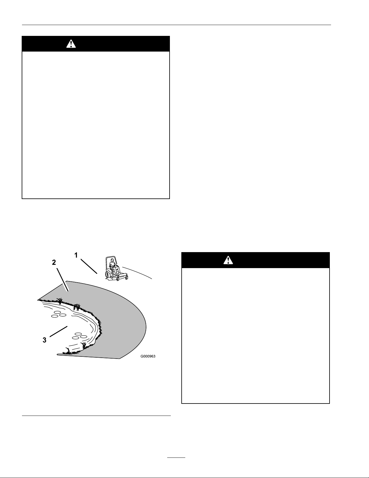
•Useawalkbehindmowerand/orahandtrimmer
neardrop-offs,ditches,steepbanksorwater.
(Figure3).
•Watchforditches,holes,rocks,dipsandrisesthat
changetheoperatingangle,asroughterraincould
overturnthemachine.
•Avoidsuddenstartswhenmowinguphillbecause
themowermaytipbackwards.
•Beawarethatoperatingonwetgrass,acrosssteep
slopesordownhillmaycausethemowertolose
traction.Lossoftractiontothedrivewheelsmay
resultinslidingandlossofbrakingandsteering.
•Alwaysavoidsuddenstartingorstoppingona
slope.Iftireslosetraction,disengagetheblades
andproceedslowlyofftheslope.
•Followthemanufacturer’srecommendationsfor
wheelweightsorcounterweightstoimprove
stability.
•Useextremecarewithgrasscatchersor
attachments.Thesecanchangethestabilityofthe
machineandcauselossofcontrol.
UsingtheRolloverProtectionSystem
(ROPS)
ARolloverProtectionSystem(rollbar)isinstalled
ontheunit.
Figure3
1.SafeZone-Usethemowerhereonslopeslessthan15
degrees
2.DangerZone-Useawalkbehindmowerand/orhand
trimmeronslopesgreaterthan15degrees,near
drop-offsandwater.
3.Water
•Removeormarkobstaclessuchasrocks,tree
limbs,etc.fromthemowingarea.Tallgrasscan
hideobstacles.
WARNING
Thereisnorolloverprotectionwhentheroll
barisdown.Wheelsdroppingoveredges,
ditches,steepbanks,orwatercancause
rollovers,whichmayresultinseriousinjury,
deathordrowning.
•Keeptherollbarintheraisedandlocked
positionanduseseatbelt.
•Lowertherollbaronlywhenabsolutely
necessary.
•DoNotwearseatbeltwhentherollbar
isdown.
•Driveslowlyandcarefully.
•Raisetherollbarassoonasclearance
permits.
•Checkcarefullyforoverheadclearances(i.e.
branches,doorways,andelectricalwires)before
10
Page 11

Safety
drivingunderanyobjectsandDoNotcontact
them.
•Intheeventofarollover,taketheunittoan
AuthorizedServiceDealertohavetheROPS
inspected.
MaintenanceandStorage
•Disengagedrives,lowerimplement,setparking
brake,stopengineandremovekeyordisconnect
sparkplugwire.Waitforallmovementtostop
beforeadjusting,cleaningorrepairing.
•Keepengineandengineareafreefrom
accumulationofgrass,leaves,excessivegrease
oroil,andotherdebriswhichcanaccumulate
intheseareas.Thesematerialscanbecome
combustibleandmayresultinare.
•LetenginecoolbeforestoringandDoNotstore
nearameoranyenclosedareawhereopenpilot
lightsorheatappliancesarepresent.
•Storemowerinawellventilatedoutdoorshelter,
building,ortrailer.
•Closefuelvalvewhenmowerisnotinuse,
includingwhilestoringortransporting.
•Theemptytank(s)shouldbetreatedasifitwas
full.
•Storethetank(s)outsideofbuildingsinanopen
wellventilatedarea,awayfromsparkandames.
•Disconnectbatteryorremovesparkplugwire
beforemakinganyrepairs.Disconnectthe
negativeterminalrstandthepositivelast.
Reconnectpositiverstandnegativelast.
•Usecarewhencheckingblades.Wraptheblade(s)
orweargloves,andusecautionwhenservicing
them.Onlyreplacedamagedblades.Never
straightenorweldthem.
•Keephandsandfeetawayfrommovingparts.
Ifpossible,DoNotmakeadjustmentswiththe
enginerunning.
•Chargebatteriesinanopenwellventilatedarea,
awayfromsparkandames.Unplugcharger
beforeconnectingordisconnectingfrombattery.
Wearprotectiveclothinganduseinsulatedtools.
DANGER
Chargingorjumpstartingthebatterymay
produceexplosivegases.Batterygasescan
explodecausingseriousinjury.
•Keepsparks,ames,orcigarettesaway
frombattery.
•Ventilatewhenchargingorusingbattery
inanenclosedspace.
•Makesureventingpathofbatteryis
alwaysopenoncebatteryislledwith
acid.
•DoNotstorethetank(s)ormachinewith
tank(s)inanareawherethetemperaturecanrise
above120°F(49°C).Ifthetemperatureexceeds
approximately160°F(71°C),thetankwillrelease
highlyammablepropanevapor.SeePreparation
intheSafetySection.
•Storethetank(s)inuprightpositionorwith
pressurereliefvalvetowardsthetop.
•DoNotdrag,drop,orabusethetank(s).
•Storageoftheemptytank(s)shouldfollowlocal
andstateregulations.
•Parkmachineonlevelground.Neverallow
untrainedpersonneltoservicemachine.
•Usejackstandstosupportcomponentswhen
required.
•Carefullyreleasepressurefromcomponentswith
storedenergy.
•Alwaysshieldeyesandfacefrombattery.
DANGER
Batteryelectrolytecontainssulfuricacid,
whichispoisonousandcancausesevere
burns.Swallowingelectrolytecanbefatalor
ifittouchesskincancausesevereburns.
•Wearsafetyglassestoshieldeyes,and
rubberglovestoprotectskinandclothing
whenhandlingelectrolyte.
•DoNotswallowelectrolyte.
•Intheeventofanaccident,ushwith
waterandcalladoctorimmediately.
11
Page 12

Safety
CAUTION
Iftheignitionisinthe“ON”positionthere
ispotentialforsparksandengagement
ofcomponents.Sparkscouldcausean
explosionormovingpartscouldaccidentally
engagecausingpersonalinjury.
Besureignitionswitchisinthe“OFF”
positionbeforechargingthebattery.
•Keepallguards,shieldsandallsafetydevicesin
placeandinsafeworkingcondition.
•Checkallboltsfrequentlytomaintainproper
tightness.
•Frequentlycheckforwornordeteriorating
componentsthatcouldcreateahazard.
WARNING
Removingstandardoriginalequipment
parts,orusingnon-Exmarkreplacement
partsandaccessoriesmayalterthewarranty,
traction,andsafetyofthemachine.Failure
touseoriginalExmarkpartscouldcause
seriousinjuryordeath.
WARNING
Hydraulicuidescapingunderpressure
canpenetrateskinandcauseinjury.Fluid
accidentallyinjectedintotheskinmustbe
surgicallyremovedwithinafewhoursbya
doctorfamiliarwiththisformofinjuryor
gangrenemayresult.
•Ifequipped,makesureallhydraulicuid
hosesandlinesareingoodcondition
andallhydraulicconnectionsandttings
aretightbeforeapplyingpressureto
hydraulicsystem.
•Keepbodyandhandsawayfrompinhole
leaksornozzlesthatejecthighpressure
hydraulicuid.
•Usecardboardorpaper,notyourhands,
tondhydraulicleaks.
•Safelyrelieveallpressureinthehydraulic
systembyplacingthemotioncontrol
leversinneutralandshuttingoffthe
enginebeforeperforminganyworkon
thehydraulicsystem.
Replaceallpartsincluding,butnotlimitedto
tires,belts,andbladeswithoriginalExmark
parts.
12
Page 13
SafetyandInstructionalDecals
Safety
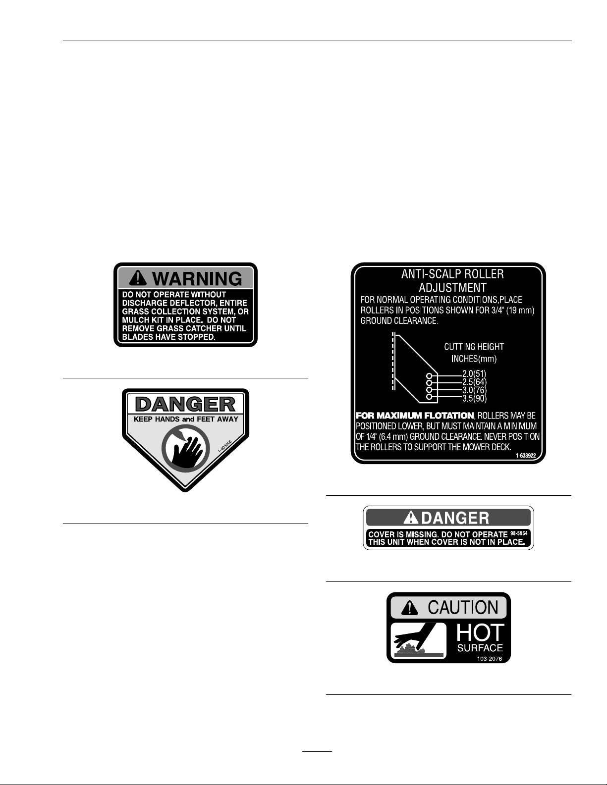
•Keepallsafetysignslegible.Removeallgrease,
dirtanddebrisfromsafetysignsandinstructional
labels.
•Replaceallworn,damaged,ormissingsafety
signs.
•Whenreplacementcomponentsareinstalled,be
surethatcurrentsafetysignsareafxedtothe
replacedcomponents.
•Ifanattachmentoraccessoryhasbeeninstalled,
makesurecurrentsafetysignsarevisible.
1-303508
•Newsafetysignsmaybeobtainedfrom
yourauthorizedExmarkequipmentdealeror
distributororfromExmarkMfg.Co.Inc.
•Safetysignsmaybeafxedbypeelingoffthe
backingtoexposetheadhesivesurface.Apply
onlytoaclean,drysurface.Smoothtoremove
anyairbubbles.
•Familiarizeyourselfwiththefollowingsafetysigns
andinstructionlabels.Theyarecriticaltothesafe
operationofyourExmarkcommercialmower.
1-633922
1-403005
98-5954
103-2076
13
Page 14
Safety
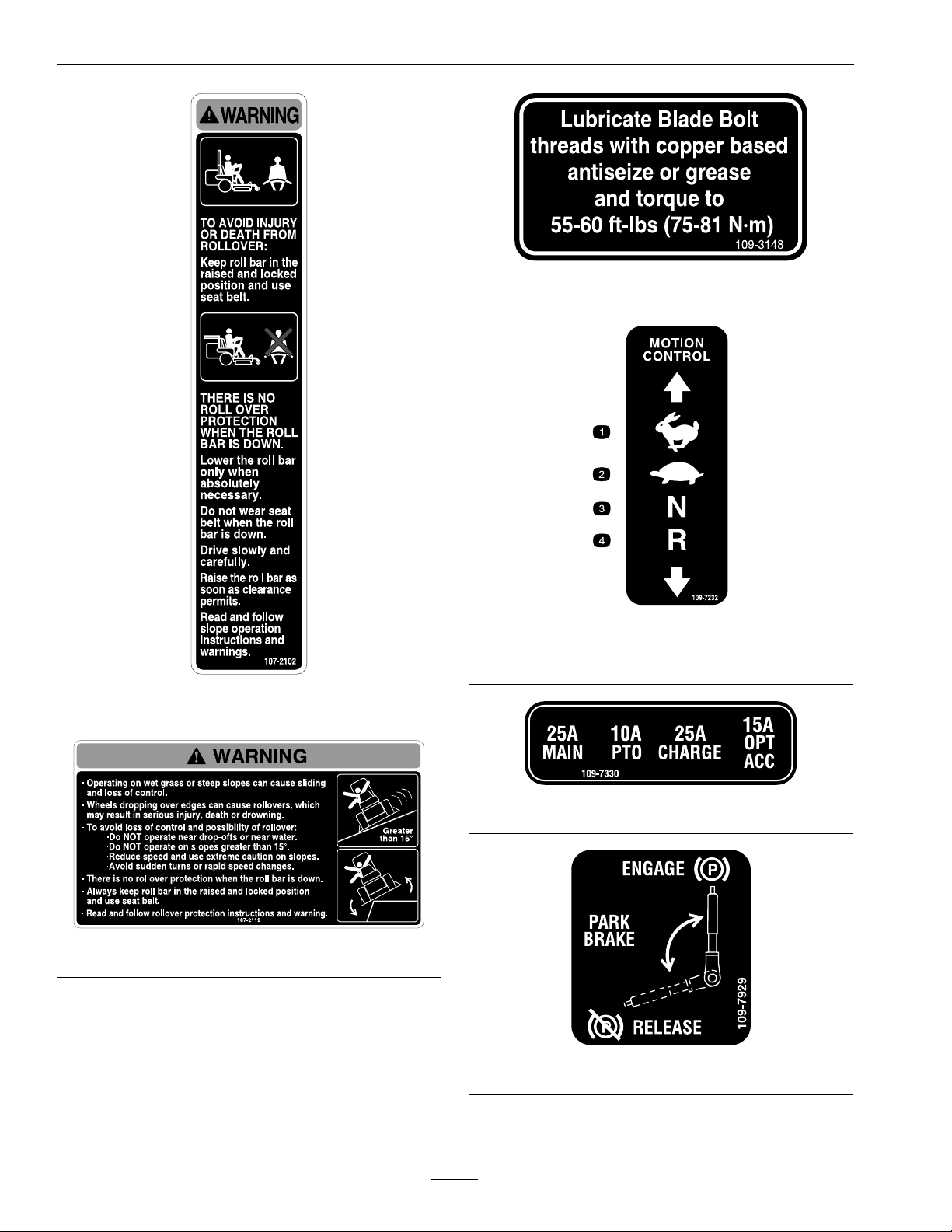
109-3148
107-2102
107-2112
109-7232
1.Fast3.Neutral
2.Slow
109-7330
109-7929
4.Reverse
14
Page 15
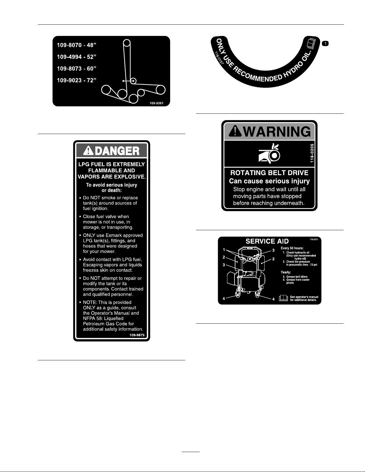
DeckDriveBeltRouting
Safety
116-0157
1.SeeOperator’smanual
109-9361
116-0205
116-0211
109-9875
15
Page 16
Safety
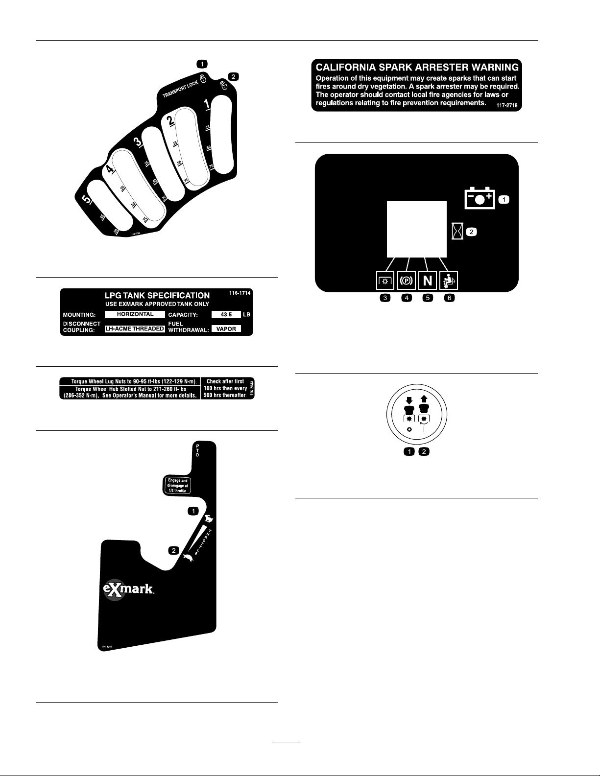
1.Latch2.Unlatch
117-2718
116-0752
HourMessageDisplay
1.HourMeter4.Neutral
116-1714
2.PTO5.Operator’spresence
switch
3.ParkingBrake6.Battery
1.Throttle-fast
2.Throttle-slow
116-2643
PTOSwitchSymbols
1.PTO–disengage2.PTO–engage
116-3261
16
Page 17
Safety
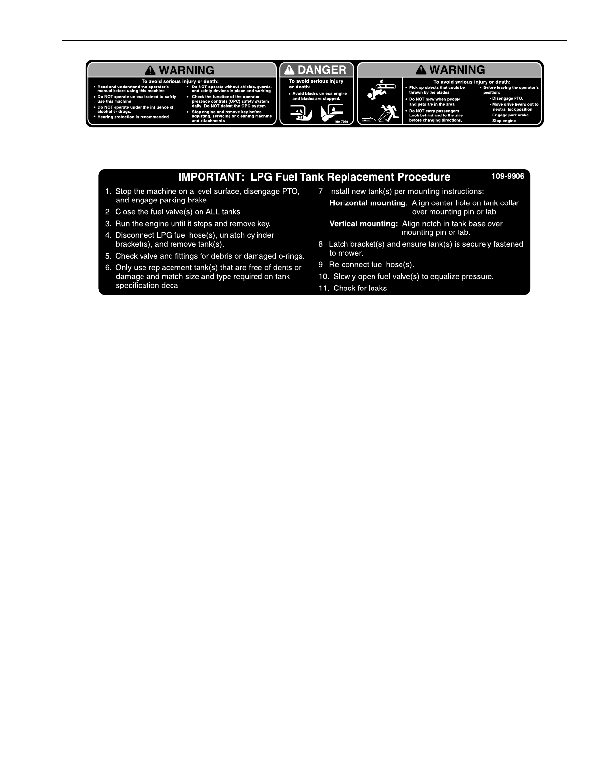
109-7069
109-9906
17
Page 18

Specications
Specications
ModelNumbers
SerialNos:850,000andHigher
LZAS29KA604LP;LZAS29KA724LP;LZZ29KA606LP
Systems
Engine
•EngineSpecications:SeeyourEngineOwner’ s
Manual
•RPM:FullSpeed:3750±50RPM(PTOnot
engaged)Idle:1500±100RPM
TankTypeandRelling
Important:TheLPGtankusedonthismower
isaspecialtankwithinternalbafesdesigned
forthisapplication.
•HorizontalTankSpecications:
–TankMaterial:Aluminum
–Capacity:43.5lb
–DisconnectCoupling:LHACMEThreaded
–FuelWithdrawal:Vapor
–FuelShut-OffValve:Rotateclockwiseto
close.
•TypeofFuel:HD5gradepropane
•Newtanksmustbeproperlylledbytrainedand
qualiedpersonnel.
•OnlyusetanksrecommendedbyExmark.Failure
todosowillresultinimproperoperationofthe
fuelsystem.
CAUTION
Undernocircumstancesshouldpropane
tankslledbeyond80%capacitybeusedin
service.
Theuseofoverlledtanksmayresultinthe
releaseofhighlyconcentratedandextremely
ammableliquidpropane.Refertothe
Safetysection.
andpreventtheenginefromoperating.Thismay
alsoresultinpermanentfuelsystemdamageandthe
releaseofhighlyammablepropaneliquidorvapor.
ElectricalSystem
•ChargingSystem:FlywheelAlternator
•ChargingCapacity:15amps
•BatteryType:BCIGroupU1
•RecommendedMinimumBatteryCCA:260CCA
•BatteryVoltage:12Volt
•LowVoltageLight—RHcontrolpanel
•Polarity:NegativeGround
•Fuses:
Allunits:
–25ampmainfuse
–25ampchargingsystemfuse
–10ampPTOfuse
–15ampaccessoryfuse
SafetyInterlockSystem
•LCDindicatorsappearforthePTO,parkbrake,
drivelevers,andoperatorpresenceinthemessage
displayontheRHcontrolpanel.
•PTOmustbedisengaged,brakeengaged,and
motioncontrolleversout(neutrallock)tostart
engine.(Itisnotnecessaryfortheoperatortobe
intheseattostarttheengine.)
•OperatormustbeinseatwhenPTOisengaged,
brakeisdisengaged,ormotioncontrolleversare
movedinorenginewillstop.
•Enginewillstopifeithertheleft,theright,or
bothleversaremovedfromneutrallockposition
whilebrakeisengaged.
Note:Useofa“forklift”typeliquidwithdrawaltank
willresultinicingorfreezingoftheLPGregulator
OperatorControls
•SteeringandMotionControl:
18
Page 19

Specications
Note:Motioncontrolleversareadjustableto
twoheights.
–Separatelevers,oneachsideoftheconsole,
controlspeedanddirectionoftravelofthe
respectivedrivewheels.
–Steeringiscontrolledbyvaryingtheposition
oftheleversrelativetoeachother.
–Movingmotioncontrolleversoutward(in
slots)locksthedrivesysteminneutral.
•PTOEngagementSwitch:Engageselectricclutch
(todrivebelt)whichengagesmowerblades.
•ParkingBrakeLever:Engagesparkingbrake.
•ParkingBrakeReleaseButton:Releasesparking
brake.
•DeckHeightAdjustmentLever:Setscutting
heighttodesiredposition.
•DeckLiftPedal:Footpedalthatliftsdeck.
•TransportLock:
–Latchingposition:Automaticallylatchesat
thetransportposition.
–Unlatchingposition:Deckdoesnotlatchat
thetransportposition.
withCustomRideSeatSuspensionorDeluxe
SuspensionSeat.Addsapproximately1inch
(2.5cm)toseatheight.SeatIsolationSystem
isstandardonallLZZ-LPunits.
•Mounting:
–LZZ-LPUnits:Hingedseatframetotiltup
seat.Heldintiltedpositionwithproprod.
Adjustableforeandaftonseattracks.
–LZAS-LPUnits:Adjustableforeandafton
seattracks.
–Armrests:
◊Standardseat:foampaddedadjustable
ip-uparmrests.
◊Suspensionseat:moldedadjustableip-up
armrests.
–SeatSafetySwitch:
Integratedseatswitch.Timedelayseatswitch
eliminatesroughgroundcut-outs.
HydrostaticGroundDriveSystem
•Twounitizedhydrostatictransmissions:
Seat
•Type:
–LZZ-LPUnits:Standardseatwithhighback,
extrawidefoampaddedseatcushionwith
internalsuspension,thickbolstering,two-tone
cover,armrests,integralsafetyswitch,and
seatvibrationisolationsystem.
–LZAS-LPUnits:Standardseatwithhigh
back,extrawidefoampaddedseatcushion
withinternalsuspension,thickbolstering,
armrests,integralsafetyswitch.
Optionalseataccessoriesforunitswithstandard
seats:
–Customridesuspensionsystemtoenhance
StandardSeat.Addsapproximately3inches
(7.6cm)toseatheight.
–Deluxesuspensionseatwithhighback,low
prolefoam-in-placecushion(dampened,
adjustablespringsuspension),armrests,and
integralsafetyswitch.Seatheightremainsthe
same.
–SeatIsolationSystemforreducedvibration,
toenhancerideofstandardseat,standardseat
–LZZ-LPUnits:
◊16ccParkeraxialpistonpump
◊280ccRossgerolermotor
–LZAS-LPUnits:
◊12ccParkeraxialpistonpump
◊240ccParkergerolermotor
•HydraulicOilType:ExmarkPremiumHydrooil.
•HydraulicOilCapacity:52oz(1.5L)perside
•HydraulicFilter:P/N116-0164
•Speeds:
–12cc
◊0-10mph(16.1km/hr)forward.
◊0-5.5mph(8.9km/hr)reverse.
–16cc
◊0-11.5mph(18.5km/hr)forward.
◊0-6mph(9.7km/hr)reverse.
•Drivewheelreleasevalvesallowmachinetobe
movedwhenengineisnotrunning.
19
Page 20

Specications
Tires&Wheels
Pneumatic(Airlled)
Quantity
Tread
Size24x12.00-12
PlyRating
Pressure
ModelLZAS-LPLZAS-LPLZZ-LP
DeckSize
Quantity
Tread
Size13x5.00-613x6.50-613x6.50-6
PlyRating
Pressure
60
222
SmoothSmoothSmooth
———
———
2
“Multi-TracC/S”
4
13psi(90kPa)
FrontCaster
Semi-Pneumatic
72
CuttingDeck
•CuttingWidth:
–60inchDeck:(152.4cm)
–72inchDeck:(182.9cm)
Drive
protection.Deckdesignallowsforbagging,
mulchingorsidedischarge.
–60inchDeck:4anti-scalprollers
–72inchDeck:4anti-scalprollers
•DeckDepth:
–60inchDeck:5.5inches(14cm)
–72inchDeck:5.5inches(14cm)
•CuttingHeightAdjustment:
Footactivatedleverisusedtoadjustthecutting
heightfrom1inch(2.5cm)to51/2inches(14
cm)in1/4inch(6.4mm)increments.
60
•MulchingKit:Optional.
Dimensions
OverallWidth:
60inchDeck72inchDeck
WithoutDeck53.0inches
(134.6cm)
DeectorUp62.5inches
(158.8cm)
DeectorDown72.8inches
(184.9cm)
59.1inches
(150.1cm)
73.5inches
(186.7cm)
84.9inches
(215.6cm)
•Discharge:Side
•BladeSize:(3ea.)
–60inchDeck:20.50inches(52.1cm)
–72inchDeck:24.50inches(62.2cm)
•BladeSpindles:
–LZZ-LPUnits:Solidsteelspindleswith1.18
inch(30mm)I.D .bearings.
–LZAS-LPUnits:Solidsteelspindleswith1.00
inch(25mm)I.D .bearings.
•DeckDrive:
Electricclutch.Shaftdiameter1.125inches(2.86
cm)
60and72inchDecks:5VSectionbeltwith
self-tensioningidler.
•Deck:
Fulloatingdeckisattachedtoout-frontsupport
frame.Anti-scalprollersprovidemaximumturf
OverallLength:
60inchDeck72inchDeck
RollBar-Up83.1inches
(211.1cm)
RollBar-Down84.8inches
(215.4cm)
86.1inches
(218.7cm)
87.8inches
(223.0cm)
OverallHeight:
RollBar-UpRollBar-Down
70.5inches(179.1cm)46.8inches(118.9cm)
20
Page 21

Specications
TreadWidth:(CentertoCenterof
Tires,Widthwise)
60inchDeck72inchDeck
DriveWheels41.6inches
(105.7cm)
CasterWheels39.5inches
(100.3cm)
43.6inches
(110.7cm)
47.1inches
(119.6cm)
WheelBase:(CenterofCasterTireto
CenterofDriveTire)
LZZ-LPUnits:
60inchDeck
50.6inches(128.5cm)
LZAS-LPUnits:
60inchDeck72inchDeck
51.6inches(131.1cm)53.6inches(136.1cm)
CurbWeight:
LZZ-LPUnits:
60inchDeck
29HPKawasakiUnits
LZAS-LPUnits:
29HPKawasaki
Units
60inchDeck72inchDeck
1283lb(582kg)1338lb(607kg)
1342lb(609kg)
AccessoryWeightTableWorksheet:
Usethetablebelowtodetermineifextraweight
isrequiredfortheunit.Identifytheaccessories
andcorrectdecksizeandplacethecorresponding
valuesintheAccessoryScorecolumn.IftheTotal
AccessoryScoremeetsthefollowing,addthe
recommendedweightkit.
Note:The72inchdeckdoesnotrequireaweightkit.
60inchDeckAccessoryScore
LightKit
Michigan
Seat/CRSS
Bagger
PneumaticCaster
Tires
MulchKit
StriperKit0
OCD02-4
HitchKit
SunshadeKit
TotalAccessoryScore
TotalAccessoryScoreRequiredWeightKit(s)
0–9
10–19
20andHigher*Two116-1173Undertoe
2
3
3
5
-5
1
2
Nonerequired
*116-1173Undertoe
boardmountweightkit
boardmountweightkits
orone116-1173Undertoe
boardmountweightkit
andone116-1238Front
toeboardmountweightkit
*60inchunitswhichalreadyhaveanundertoeboard
mountweightasstandardrequires116-1238fronttoe
boardtopmountkitinsteadof116-1173.
21
Page 22

ProductOverview
TorqueRequirements
BoltLocation
BladeDriveSheave
MountingNut
LZZ-LPUnits:
LZAS-LPUnits:
CutterHousingSpindle
Nut(LZZ-LPUnitsOnly)
BladeMountingBolt
(lubricatewithanti-seize)
Anti-ScalpRollerHex
Capscrew
LZZ-LPUnits:See
Figure18
Anti-ScalpRollerNyloc
Nut
LZZ-LPUnits:See
Figure18
LZAS-LPUnits:See
Figure19
Torque
90-110ft-lb(122-149N-m)
140-145ft-lb(190-197
N-m)
160-185ft-lb
(217-251N-m)
55-60ft-lb(75-81N-m)
50-55ft-lb(68-75N-m)
30-35ft-lb(41-47N-m)
30-35ft-lb(41-47N-m)
ProductOverview
1.RolloverProtection
System(ROPS)
2.LPGtank
3.Seatbelt
4.Motioncontrollevers
Figure4
5.Heightofcutadjustment
6.Parkingbrake
7.Enginecontrols
Anti-ScalpRollerWhizlock
Nut
LZAS-LPUnits:See
Figure19
EngineMountingBolts
WheelLugNuts
WheelMotorMounting
Bolts
WheelHubSlottedNut211-260ft-lb
RolloverProtection
System(RollBar)1/2
inchMountingBolts
ClutchRetainingBolt
(securedwiththreadlocker)
HydroParkBrakeCable
Anchor1/2inchMounting
Bolt(securedwith
threadlocker)
30-35ft-lb(41-47N-m)
27-33ft-lb(37-45N-m)
90-95ft-lb(122-129N-m)
72-77ft-lb(98-104N-m)
(286-352N-m)
75-80ft-lb(102-108N-m)
55-60ft-lb(75-81N-m)
67-89ft-lb(91-121N-m)
22
Page 23

Operation
Operation
Note:Determinetheleftandrightsidesofthe
machinefromthenormaloperatingposition.
Controls
MotionControlLevers
Themotioncontrolleverslocatedoneachsideof
theconsolecontroltheforwardandreversemotion
ofthemachine.
Movingtheleversforwardorbackwardturns
thewheelonthesamesideforwardorreverse
respectively.Wheelspeedisproportionaltothe
amounttheleverismoved.
Movingtheleversoutwardfromthecenterposition
intotheT-slotlocksthemintheneutralposition
(Figure5).
Whenthemotioncontrolleversareintheneutral
position,theLCDindicatorappearsinthemessage
displayontheRHconsole(seeFigure9).
Thethrottleisusedtocontrolenginespeed.Moving
thethrottleleverforwardwillincreaseenginespeed
andmovingthethrottlelevertotherearwilldecrease
enginespeed.Movingthethrottleforwardintothe
detentisfullthrottle.
Figure6
RightConsole
1.Fuses
2.Messagedisplay5.Throttle
3.Ignitionswitch
4.PTOengagementswitch
1.Neutrallockposition
(handlesout)
2.Neutraloperateposition
(handlesin)
3.FrontofUnit
ThrottleControl
BrakeLever
Locatedonrightsideofunit,justtothefrontofthe
RHmotioncontrollever.
Thebrakeleverengagesaparkingbrakeonthedrive
wheels.
Note:TheLCDindicatorappearsinthemessage
displayontheRHconsolewhentheparkbrakeis
engaged(seeFigure9).
Pulltheleverupandrearwardtoengagethebrake.
Depressthereleasebuttonandpushdownwardto
disengagethebrake.
Figure5
4.Forward
5.Neutral(operate)
6.Reverse
Locatedonrightconsole(redlever)(seeFigure6).
23
Page 24

Operation
Figure7
1.Releasebutton2.Parkbrake
Theunitmustbetieddownandbrakeengagedwhen
transporting.
IgnitionSwitch
Figure9
1.LCDIndicators
2.Lowvoltageindicatorlight
3.Hour/Voltagedisplay
Locatedonrightconsole(seeFigure6).
Theignitionswitchisusedtostartandstopthe
engine.Theswitchhasthreepositions“OFF”,“ON”
and“START”.Insertkeyintoswitchandrotate
clockwisetothe“ON”position.Rotateclockwiseto
thenextpositiontoengagethestarter(keymustbe
heldagainstspringpressureinthisposition).Allow
thekeytoreturntothe“on”positionimmediately
aftertheenginestarts.
Figure8
1.Off3.Start
2.On
Note:Brakemustbeengaged,motioncontrol
leversout(neutrallockposition)andPTOswitch
disengagedtostartengine.(Itisnotnecessaryforthe
operatortobeintheseattostarttheengine.)
Thehourmeterisrecordingwhenthedecimalpoint
isashinginHour/Voltagedisplay.
Hoursaredisplayedwhenthekeyisofforwhenthe
machineisrunning.
Note:Iftheignitionkeyisturnedtothe“ON”
positionforafewsecondsbeforecrankingthe
engine,thebatteryvoltagewilldisplayinthearea
wherethehoursarenormallydisplayed.
Note:TheLCDindicatorsappearwheneach
controlmeetsthe“safetostart”mode(e.g.the
indicatorturnsonwhentheoperatorisintheseat.)
FuelValve
LocatedontheLPGfueltank.
Thefuelvalveisusedtoopenandclosethefuel
supplywhenthemachineisnotinuse,during
transporttoandfromthejobsite,andwhenparked
insideawell-ventilatedbuilding.
Rotatethefuelvalveclockwisetoturnoffthefuel.
Rotatefuelvalvecounterclockwisetoturnonthefuel.
FuelGauge
LocatedontheLPGfueltank.
HourMeter
Locatedontherightconsoleinthemessagedisplay
(seeFigure6andFigure9).
Thehourmeterrecordsthenumberofhoursthat
theenginehasrun.
ThisgaugemonitorstheamountofliquidLPGin
thefueltank.
SafetyPressureReliefValve
LocatedontheLPGfueltank.
Thesafetypressurereliefvalverelievestheexcess
pressureintheLPGtank.
24
Page 25

Operation
Important:Thisvalvehasaprotectiveplastic
capthatshouldNEVERberemoved.Ifthe
capisdamagedormissing,contacttrainedand
qualiedpersonnelimmediately .
LPGCylinderBrackets
Thebracketsarelocatedontheenginedeck.
TheLPGcylinderbracketsareusedtofastenthe
removableLPGtanktothemower.
DriveWheelReleaseValves
WARNING
Handsmaybecomeentangledintherotating
drivecomponentsbelowtheenginedeck,
whichcouldresultinseriousinjuryordeath.
Stopengine,removekey,allowallthemoving
partstostopbeforeaccessingthedrivewheel
releasevalves.
Toreleasethedrivesystem(seeitem1inFigure10),
rotatethehandle1/4turntotheverticalposition
untilithitsagainstthestop.
Toresetthedrivesystem(seeitem2inFigure10),
rotatethehandle1/4turntothehorizontalposition
untilithitsagainstthestop.
Note:Thehandlemustbehorizontalandagainst
thestopforoperation.
DoNottowmachine.
PTOEngagementSwitch
Locatedonrightconsole(seeFigure6).
Switchmustbepulledout(up)toengagetheblades.
Switchispushedintodisengagetheblades.
TheLCDindicatorwillappearwhenthePTOswitch
isdisengaged(seeFigure9).
LowVoltageIndicator
Locatedontherightconsoleinthemessagedisplay
(seeFigure6andFigure9).
WARNING
Theengineandhydraulicdriveunitscan
becomeveryhot.Touchingahotengineor
hydraulicdriveunitscancausesevereburns.
Allowtheengineandhydraulicdriveunitsto
coolcompletelybeforeaccessingthedrive
wheelreleasevalves.
Locatedonthebackoftheunitizedhydraulicdrive
units,belowtheenginedeck.
Duringnormaloperatingconditions,thedrivewheel
releasevalvesarepositionedhorizontally .Ifthe
machinehastobepushedbyhand,thevalvesmust
beinthe“released”position(seeFigure10).
Figure10
1.Handlein“released”position
2.Handlein“operating”position
Alowvoltagecondition(lessthan12.3volts)exists
whentheLCDindicatorappearsonthemessage
displaywhiletheengineisrunning.
Iftheignitionkeyisturnedtothe“ON”positionfor
afewsecondsbeforecrankingtheengine,thebattery
voltagewilldisplayintheareawherethehoursare
normallydisplayed.
Note:Theindicatornormallyappearswhenthe
engineisoffandthekeyswitchisturnedtothe
“ON”position.
DeckLiftPedal
Locatedattherightfrontcorneroftheoorpan.
Pushthepedalforwardwithyourfoottoraisethe
cuttingdeck.Allowthepedaltomoverearwardto
lowerthecuttingdecktothecutheightthathasbeen
set.
TransportLock
Locatedontheheightofcutadjustmentplatestothe
rightoftheparkingbrake.
Positioninthetransportlatchingpositionto
automaticallylatchthecuttingdeckwhenraisedto
thetransportposition(seeitem1inFigure11).
25
Page 26

Operation
Inthenon-latchingposition,thedeckwill
automaticallyreturntothecuttingheightwhenthe
pedalislowered(seeitem3inFigure11).
Figure11
1.Latchingposition3.Non-latchingposition
2.Transportlockcontrol
Pre-Start
LPGtankssuppliedfromExmarkDoNotcontain
LPGfuelforshippingreasonsandsafety.Havethe
LPGtankslledbytrainedandqualiedpersonnel.
Forbestresults,useclean,freshHD5gradepropane.
DoNotallowtheLPGtankstobeoverlled.
OverllingLPGtanksbuildsexcesspressurewithin
thetankwhichcausesthereliefvalvetoopen.
4.Toreturntotheoperateposition,raisetheroll
bar,andthenrotateknobs90°sothatthetabs
interlockpartially.Applyforwardpressuretothe
rollbarupperhoopandobservethattheknobs
returntothecompletelylatchedposition.
Figure12
1.Rollbarupperhoop
2.Knobin“latched”position
3.Pullknobtounlatch
4.Rotate90°toholdunlatched
5.Knobin“unlatched”position
Makesureyouunderstandthecontrols,their
locations,theirfunctions,andtheirsafety
requirements.
RefertotheMaintenancesectionandperformallthe
necessaryinspectionandmaintenancesteps.
OperatingInstructions
RaisetheRolloverProtectionSystem
(ROPS)
Important:Therollbarisanintegraland
effectivesafetydevice.Keeptherollbarinthe
raisedandlockedpositionwhenoperatingthe
mower.Lowertherollbartemporarilyonlywhen
absolutelynecessary.
1.Theknobmustbecompletelylatchedwiththe
tabsinterlockingasshowninFigure12tolock
therollbarintheraised,operateposition.
2.Applyforwardpressuretotheupperhoopofthe
rollbar.
3.Pulltheknobandrotate90°toholdinthe
unlatchedpositiontolowertherollbar.
5.Makesuretheknobsarefullyengagedwiththe
rollbarintheraisedposition.Theupperhoopof
therollbarmayneedtobepushedforwardor
pulledrearwardtogetbothknobsfullyengaged
(seeFigure13).
Figure13
1.Engaged2.Partiallyengaged—Do
NotoperatewithROPS
inthiscondition.
Important:Alwaysusetheseatbeltwiththe
rollbarintheoperate(raised)position.Ensure
26
Page 27

Operation
thattherearpartoftheseatissecuredwiththe
seatlatch.
OpentheFuelValve
1.Slowlyopenthefuelvalvetoequalizethepressure
inthetank.Thefuelvalveislocatedonthetop
endoftheLPGtank.Ifthefuelvalveisopened
tooquickly ,thepressurereliefvalveisequipped
withabackpressurecheckvalvethatwillshutoff
thefuelsupply.Ifthishappens,closethefuel
valvecompletelyandwaitveseconds.Slowly
openthefuelvalve.
2.Rotatethefuelvalvecounterclockwisetoturnon
thefuel.Ifleaksaredetected,refertotheleak
informationintheInspectionsectioninSafety.
StartingtheEngine
1.Movethemotioncontrolleversouttotheneutral
lockposition.
2.Pullupandbackontheparkingbrakeleverto
engagetheparkingbrake.
DANGER
Anuncovereddischargeopeningwillallow
objectstobethrowninanoperator’sor
bystander’sdirection.Also,contactwiththe
bladecouldoccur.Thrownobjectsorblade
contactcancauseseriousinjuryordeath.
Neveroperatethemowerwiththedischarge
deectorraised,removed,oralteredunless
thereisagrasscollectionsystemormulch
kitinplaceandworkingproperly.
ThePTOpush-pullswitchengagesthecuttingblades.
Besurethatallpersonsareclearofthemowerdeck
anddischargeareabeforeengagingPTO.
Important:Operatormustbeinseatbeforethe
PTOcanbeengaged.
1.Setthethrottlemidwaybetweenthe“SLOW”
and“FAST”positions.
2.PullthePTOswitchoutwardtoengagethe
blades.
3.PushinonthePTOswitchtothe“STOP”
position.
Note:Itisnotnecessaryfortheoperatortobe
intheseattostarttheengine.
4.Placethethrottleinthe“SLOW”position.
5.Turnignitionswitchtothe“START”position.
Releasetheswitchassoonastheenginestarts.
Important:DoNotcranktheengine
continuouslyformorethantensecondsata
time.Iftheenginedoesnotstart,allowa60
secondcool-downperiodbetweenstarting
attempts.Failuretofollowtheseguidelines
canburnoutthestartermotor.
EngagingthePTO
DANGER
Therotatingbladesunderthemowerdeck
aredangerous.Bladecontactcancause
seriousinjuryorkillyou.
DoNotputhandsorfeetunderthemower
ormowerdeckwhenthebladesareengaged.
3.Placethethrottleinthe“FAST”positiontobegin
mowing.
DisengagingthePTO
1.Setthethrottlemidwaybetweenthe“SLOW”
and“FAST”positions.
2.PushthePTOswitchintodisengagetheblades.
StoppingtheEngine
1.Bringtheunittoafullstop.
2.DisengagethePTO.
3.Movethemotioncontrolleversouttotheneutral
lockposition.
4.Engagetheparkingbrake.
5.Placethethrottleinthe“SLOW”position.
6.Turnoffthefuelvalveandallowtheengineto
runoutoffuel.Failuretodothismaycausethe
engineto“ood”whenre-starting.
7.Turntheignitionswitchtothe“OFF”position
oncetheenginehasstopped.
8.Removethekeytopreventchildrenorother
unauthorizedpersonsfromstartingengine.
27
Page 28

Operation
DrivingtheMachine
CAUTION
Machinecanspinveryrapidlybypositioning
onelevertoomuchaheadoftheother.
Operatormaylosecontrolofthemachine,
whichmaycausedamagetothemachine
orinjury.
•Usecautionwhenmakingturns.
•Slowthemachinedownbeforemaking
sharpturns.
Important:Tobeginmovement(forwardor
backward)theoperatormustbeintheseat,the
brakelevermustbedisengaged(pusheddown)
beforethemotioncontrolleverscanbemovedin
ortheenginewillstop.
Whenthemotioncontrolleversarepositionedfully
outward(apart)intheT-slot,thedrivesystemisin
theneutrallockposition(Figure14).
1.Neutrallockposition
(handlesout)
2.Neutraloperateposition
(handlesin)
3.FrontofUnit
Figure14
4.Forward
5.Neutral(operate)
6.Reverse
Note:The“N”LCDindicatorappearswhenboth
leversareintheneutrallockposition.
Whenthemotioncontrolleversaremoveddirectly
inward(together)thedrivesystemisintheneutral
operateposition.
DrivingForward
1.Releasetheparkingbrake.
2.Movethemotioncontrolleversinwardtothe
centertotheneutralposition.
3.Tomoveforwardinastraightline,moveboth
leversforwardwithequalpressure.
Toturnleftorright,pullthemotioncontrollever
backtowardneutralinthedesiredturndirection.
Themachinewillmovefasterthefartherthe
motioncontrolleversaremovedfromtheneutral
position.
4.Tostop,positionbothmotioncontrolleversin
theneutraloperateposition.
1.FrontofUnit
2.Forward4.Reverse
28
Figure15
3.Neutral
Page 29

Operation
DrivinginReverse
1.Movethemotioncontrolleversinwardtothe
neutraloperateposition.
2.Tomoverearwardinastraightline,moveboth
leversrearwardwithequalpressure.
Toturnright,releasepressureontheRHmotion
controlleverandtherearofthemachinewill
movetowardstherearandtotheright.
Toturnleft,releasepressureontheLHmotion
controlleverandtherearofthemachinewill
movetowardstherearandtotheleft.
3.Tostop,positionbothmotioncontrolleversin
theneutraloperateposition.
AdjustingtheCuttingHeight
Thecuttingheightofthemowerdeckisadjusted
from1to51/2inches(2.5cmto14cm)in1/4inch
(6.4mm)increments.
1.Stopthemachineandmovethemotioncontrol
leversoutwardtotheneutrallockedposition.
2.DisengagethePTO.
3.Positionthetransportlockinthelatching
position.
4.Raiseandlockthedecktothe51/2inch(14cm)
transportposition(Figure16).
Thedeckisraisedbypushingthefootoperated
deckliftpedalforward.Thepedalislocatedatthe
frontrightcorneroftheoorpan.
Note:Whenchangingthecuttingheight
positions,alwayscometoacompletestop
anddisengagethePTO.
5.Inserttheheightadjustmentpinintothehole
correspondingtothedesiredcuttingheight.
Seethedecalonthesideofthedeckliftplatefor
cutheights.
6.Pushthedeckliftpedal,releasethetransportlock
andallowthedecktolowertothecuttingheight.
AdjustingtheAnti-ScalpRollers
Itisrecommendedtochangetheanti-scalproller
position,whentheheightofcuthaschanged.
1.Stopthemachineandmovethemotioncontrol
leversoutwardtotheneutrallockedposition.
2.DisengagethePTO.
3.Engagetheparkbrake.
4.Stoptheengine,removethekeyandwaitforall
movingpartstostop.
5.Afteradjustingtheheightofcut:
•LZZ-LPUnits:Adjusttheanti-scalprollers
byremovingthebushing,springdiscwasher
andbolt.
•LZAS-LPUnits:Adjusttheanti-scalprollers
byremovingthenylocnut,bushing,spring
discwasherandwhizlocknut.
6.Placetherollersinoneofthepositionsshown
(Figure17).Rollerswillmaintain3/4inch(19
mm)clearancetothegroundtominimizegouging
androllerwearordamage.
Figure16
LZAS-LPUnitShown
1.Deckfootpedal3.Heightofcutdecal
2.Heightadjustmentpin4.Transportlockcontrol
Figure17
Forcuttingheightsabove3.5inches(90mm)usethe
bottomhole.Therollerswillstillbeeffectiveagainst
scalping.
1.Anti-scalproller
mountingbracket
2.Cuttingheight
ForMaximumDeckFlotation,placetherollers
oneholepositionlower.Rollersshouldmaintain
29
Page 30

Operation
1/4inch(6.4mm)clearancetotheground.Do
Notadjusttherollerstosupportthedeck.
7.ForLZZ-LPUnits:Besuretherollerboltsare
installedwiththespringdiscwasherbetween
theheadoftheboltandthemountingbracket
(Figure18).
ForLZAS-LPUnits:Besurethewhizlocknuts
areinstalledwiththespringdiscwasherbetween
theheadofthenutandthemountingbracket
(Figure19).
Note:Thefootoperateddeckliftassistlever
canbeusedtomomentarilyliftthedecktoclear
objects.BesurethatPTOisdisengaged.
•ForLZZ-LPUnits:
Torquethe3/8–24x2Gr8hexcapscrewto
50–55ft-lb(68–75N-m)(Figure18).
1.Springdiscwasher
(conetowardsnut)
2.Frontrightanti-scalp
bracketshown
Figure19
3.3/8nyloc-torqueto30-35
ft-lb(41-47N-m)
4.3/8-16whizlocknut
torqueto30-35ft-lb
(41-47N-m)
Figure18
1.Springdiscwasher
(conetowardsbolthead)
2.Frontrightanti-scalp
bracketshown
3.3/8nyloc-torqueto30-35
4.3/8-24x2GR8torqueto
•ForLZAS-LPUnits:
A.Torquethe3/8–16whizlocknutto30-35
ft-lb(41-47N-m)(Figure19).
B.Torquethe3/8nylocnutto30–35ft-lb
(41-47N-m).
ft-lb(41-47N-m)
50-55ft-lb(68-75N-m)
Transporting
TransportingaUnit
Useaheavy-dutytrailerortrucktotransportthe
machine.Lockbrakeandblockwheels.Securely
fastenthemachinetothetrailerortruckwithstraps,
chains,cable,orropes.Besurethatthetrailerortruck
hasallnecessarylightingandmarkingasrequiredby
law .Secureatrailerwithasafetychain.
CAUTION
Thisunitdoesnothaveproperturn
signals,lights,reectivemarkings,ora
slowmovingvehicleemblem.Drivingona
streetorroadwaywithoutsuchequipment
isdangerousandcanleadtoaccidents
causingpersonalinjury.Drivingonastreet
orroadwaywithoutsuchequipmentmayalso
beaviolationofStatelawsandtheoperator
maybesubjecttotrafcticketsand/ornes.
DoNotdriveaunitonapublicstreetor
roadway.
30
Page 31

Operation
WARNING
Loadingaunitonatrailerortruckincreases
thepossibilityofbackwardtip-over.
Backwardtip-overcouldcauseseriousinjury
ordeath.
•Useextremecautionwhenoperatinga
unitonaramp.
•Useonlyasingle,fullwidthramp;Do
Notuseindividualrampsforeachside
oftheunit.
•Ifindividualrampsmustbeused,use
enoughrampstocreateanunbroken
rampsurfacewiderthantheunit.
•DoNotexceeda15°anglebetweenramp
andgroundorbetweenrampandtrailer
ortruck.
•Avoidsuddenaccelerationwhiledriving
unituparamptoavoidtippingbackward.
•Avoidsuddendecelerationwhilebacking
unitdownaramptoavoidtipping
backward.
WARNING
Loadingthemowerontoatrailerwithout
strongenoughorproperlysupportedramps
couldbedangerous.Therampscould
collapsecausingtheunittofall,whichcould
causeinjury.
•Useproperrampsthataresecuredtothe
truckortrailer.
tipping,orphysicaldamagerelativetoother
tanksortothestoragecagewhileintransit.
–Placetankssothatvalves,ttings,orgauges
areprotectedfromphysicaldamageduring
transport.
•Placetank(s)inawell-ventilatedtrailer.
•DoNotstorethetank(s)ormachinewith
tank(s)inanareawherethetemperaturecanrise
above120°F(49°C).Ifthetemperatureexceeds
approximately160°F(71°C),thetankwillrelease
highlyammablepropanevapor.SeePreparation
intheSafetySection.
•DoNottransportLPGtank(s)inthepassenger
spaceofavehicle.
•DoNottransportleakingfueltanks.
•Trailersmusthaveappropriatemarkingsto
transportLPG.
•FollowNFPA58andstateandlocalregulations
fortransportingLPG.
LoadingaUnit
Useextremecautionwhenloadingunitsontrailersor
trucks.Onefullwidthrampthatiswideenoughto
extendbeyondthereartiresisrecommendedinstead
ofindividualrampsforeachsideoftheunit.The
lowerrearsectionofthetractorframeextendsback
betweentherearwheelsandservesasastopfor
tippingbackward.Havingafullwidthrampprovides
asurfacefortheframememberstocontactifthe
unitstartstotipbackward.Ifitisnotpossibletouse
onefullwidthramp,useenoughindividualrampsto
simulateafullwidthcontinuousramp.
•Keepfeetandlegsoutfromunderthe
unitwhenloadingandunloading.
•Ifnecessary,useassistancewhenloading.
ConsulttheNFPA58:LiqueedPetroleumGas
CodeforadditionalinformationregardingLPG
transportation.
•Besurethefuelvalveisclosedonthetank(s).
•PlacespareLPGtank(s)inaDOTapproved
storagecage.
–Transporttanksinanupright,verticaland
securepositiontominimizemovement,
Rampshouldbelongenoughsothattheangles
betweentherampandthegroundandtherampand
thetrailerortruckdonotexceed15°.Asteeperangle
maycausemowerdeckcomponentstogetcaughtas
theunitmovesfromramptotrailerortruck.Steeper
anglesmayalsocausetheunittotipbackward.If
loadingonornearaslope,positionthetraileror
trucksoitisonthedownsideoftheslopeandthe
rampextendsuptheslope.Thiswillminimizethe
rampangle.Thetrailerortruckshouldbeaslevel
aspossible.
Important:DoNotattempttoturntheunit
whileontheramp,youmaylosecontroland
driveofftheside.
31
Page 32

Operation
Avoidsuddenaccelerationwhendrivinguparamp
andsuddendecelerationwhenbackingdownaramp.
Bothmaneuverscancausetheunittotipbackward.
32
Page 33

Maintenance
Note:Determinetheleftandrightsidesofthemachinefromthenormaloperatingposition.
Maintenance
WARNING
Whilemaintenanceoradjustmentsarebeing
made,someonecouldstarttheengine.
Accidentalstartingoftheenginecould
seriouslyinjureyouorotherbystanders.
Removethekeyfromtheignitionswitch,
engageparkingbrake,andpullthewire(s)
offthesparkplug(s)beforeyoudoany
maintenance.Alsopushthewire(s)aside
soitdoesnotaccidentallycontactthespark
plug(s).
RecommendedMaintenanceSchedule(s)
MaintenanceService
Interval
Aftertherst5hours
Aftertherst100hours
MaintenanceProcedure
•Changetheengineoil.
•Checkthewheelhubslottednuttorquespecications.
•Checkthewheellugnuts.
•Checktheparkbrakeadjustment.
WARNING
Theenginecanbecomeveryhot.T ouching
ahotenginecancausesevereburns.
Allowtheenginetocoolcompletelybefore
serviceormakingrepairsaroundtheengine
area.
Beforeeachuseordaily
Every40hours
Every50hours
Every100hours
Every200hours
Every250hours
•Checktheengineoillevel.
•Checkthemowerblades.
•Checkthesafetyinterlocksystem.
•Checktherolloverprotectionssystems(rollbar)knobs.
•Checktheseatbelt.
•Checkforloosehardware.
•ChecktheLPGtankandcomponents.
•Cleantheengineandexhaustsystemarea.
•Cleanthehydrofancoolingguards.
•Cleanthegrassanddebrisbuild-upfromthemachineandcuttingdeck.
•Cleanthegrassbuild-upfromunderthecuttingdeck.
•ChecktheentireLPGfueldeliverysystem.
•Checkthehydraulicoillevel.
•Checkthetirepressures.
•Checktheconditionofthebelts.
•Changetheengineoil.(Mayneedmoreoftenundersevereconditions.)
•Lubricatethedeckliftpivots.
•Removetheengineshroudsandcleanthecoolingns.
•Lubricatethebrakehandlepivot.
•Checkthesparkplugs.
•Replacetheprimaryaircleanerelement—checksecondaryaircleanerelement;replaceif
dirty.(Mayneedmoreoftenundersevereconditions.SeetheEngineOwner’sManualfor
additionalinformation.)
33
Page 34

Maintenance
MaintenanceService
Interval
Every500hours
Yearly
MaintenanceProcedure
•Replacethesecondaryaircleanerelement(Mayneedmoreoftenundersevereconditions.
SeetheEngineOwner’ sManualforadditionalinformation.)
•Changethehydrauliclteranduid.
•Checkthewheelhubslottednuttorquespecications.
•Checkthewheellugnuts.
•Checktheparkbrakeadjustment.
•Greasethedeckandpumpidlerpivots.
•Greasethefrontcasterpivots.
PeriodicMaintenance
CheckEngineOilLevel
ServiceInterval:Beforeeachuseordaily
1.Stopengineandwaitforallmovingpartstostop.
Makesureunitisonalevelsurface.
2.Checkwithenginecold.
3.Cleanareaarounddipstick.Removedipstick
andwipeoiloff.Reinsertthedipstickaccording
totheenginemanufacturer’srecommendations.
Removethedipstickandreadtheoillevel.
4.Iftheoillevelislow ,wipeofftheareaaroundthe
oilllcap,removecapandlltothe“FULL”
markonthedipstick.Useoilasspeciedin
EngineOwner’sManual.DoNotoverll.
Important:DoNotoperatetheenginewiththe
oillevelbelowthe“LOW”(or“ADD”)markon
thedipstick,oroverthe“FULL”mark.
performanceandservicelife.Topreserveoptimum
batteryperformanceandlife,rechargebatteriesin
storagewhentheopencircuitvoltagedropsto12.4
volts.
Note:Topreventdamageduetofreezing,battery
shouldbefullychargedbeforeputtingawayfor
winterstorage.
Checkthevoltageofthebatterywithadigital
voltmeterorwiththemessagedisplay.Iftheignition
keyisturnedtothe“on”positionforafewseconds,
thebatteryvoltagewillbedisplayedintheareawhere
thehoursarenormallydisplayed.Locatethevoltage
readingofthebatteryinthetableandchargethe
batteryfortherecommendedtimeintervaltobring
thechargeuptoafullchargeof12.6voltsorgreater.
Important:Makesurethenegativebatterycable
isdisconnectedandthebatterychargerusedfor
chargingthebatteryhasanoutputof16voltsand
7ampsorlesstoavoiddamagingthebattery(see
chartforrecommendedchargersettings).
CheckBatteryCharge
ServiceInterval:Asrequired
WARNING
CALIFORNIA
Proposition65Warning
Batteryposts,terminals,andrelated
accessoriescontainleadandlead
compounds,chemicalsknowntotheStateof
Californiatocausecancerandreproductive
harm.Washhandsafterhandling.
Allowingbatteriestostandforanextendedperiodof
timewithoutrechargingthemwillresultinreduced
Voltage
Reading
12.6or
greater
12.4–12.675–100%
12.2–12.450–75%
12.0–12.225–50%
34
Percent
Charge
100%
Maximum
Charger
Settings
16volts/7
amps
16volts/7
amps
16volts/7
amps
14.4volts/4
amps
Charging
Interval
No
Charging
Required
30Minutes
1Hour
2Hours
Page 35

Maintenance
Voltage
Reading
11.7–12.00–25%
11.7orless
Percent
Charge
0%
Maximum
Charger
Settings
14.4volts/4
amps
14.4volts/2
amps
RecommendedJump
StartingProcedure
ServiceInterval:Asrequired
1.Checktheweakbatteryforterminalcorrosion
(white,green,orblue“snow”),itmustbecleaned
offpriortojumpstarting.Cleanandtighten
connectionsasnecessary.
CAUTION
Corrosionorlooseconnectionscancause
unwantedelectricalvoltagespikesatanytime
duringthejumpstartingprocedure.
Charging
Interval
3Hours
6Hoursor
More
CAUTION
Connectingthejumpercablesincorrectly
(wrongpolarity)canimmediatelydamage
theelectricalsystem.
Becertainofbatteryterminalpolarityand
jumpercablepolaritywhenhookingup
batteries.
Note:Thefollowinginstructionsareadapted
fromtheSAEJ1494Rev.Dec.2001–Battery
BoosterCables–SurfaceVehicleRecommended
Practice(SAE–SocietyofAutomotive
Engineers).
WARNING
Batteriescontainacidandproduceexplosive
gases.
•Shieldtheeyesandfacefromthebatteries
atalltimes.
•DoNotleanoverthebatteries.
DoNotattempttojumpstartwithlooseor
corrodedbatteryterminalsordamagetothe
enginemayoccur.
DANGER
Jumpstartingaweakbatterythatiscracked,
frozen,haslowelectrolytelevel,oran
open/shortedbatterycell,cancausean
explosionresultinginseriouspersonalinjury.
DoNotjumpstartaweakbatteryifthese
conditionsexist.
2.Makesuretheboosterisagoodandfullycharged
leadacidbatteryat12.6voltsorgreater.Use
properlysizedjumpercables(4to6AWG)with
shortlengthstoreducevoltagedropbetween
systems.Makesurethecablesarecolorcodedor
labeledforthecorrectpolarity.
Note:Besuretheventcapsaretightandlevel.
Placeadampcloth,ifavailable,overanyvent
capsonbothbatteries.Besurethevehiclesdo
nottouchandthatbothelectricalsystemsare
offandatthesameratedsystemvoltage.These
instructionsarefornegativegroundsystemsonly.
3.Connectthepositive(+)cabletothepositive(+)
terminalofthedischargedbatterythatiswiredto
thestarterorsolenoidasshowninFigure20.
35
Page 36

Maintenance
Figure20
1.Positive(+)cableondischargedbattery
2.Positive(+)cableonboosterbattery
3.Negative(–)cableontheboosterbattery
4.Negative(–)cableontheengineblock
5.Boosterbattery
6.Dischargedbattery
7.Engineblock
Figure21
1.Installbushinginbladepriortoinstallingbushingin
spindle.
B.Installbushing/bladeassemblyintospindle.
Makesurethesplinesonthebushingare
engagedinthespindlebeforetighteningthe
bolt.
4.Connecttheotherendofthepositivecabletothe
positiveterminaloftheboosterbattery.
5.Connecttheblacknegative(–)cabletotheother
terminal(negative)oftheboosterbattery.
6.MAKETHEFINALCONNECTIONON
THEENGINEBLOCKOFTHESTALLED
VEHICLE(NOTTOTHENEGATIVEPOST)
AWAYFROMTHEBATTERY .STANDBACK.
7.Startthevehicleandremovethecablesinthe
reverseorderofconnection(theengineblock
(black)connectionisthersttodisconnect).
CheckMowerBlades
ServiceInterval:Beforeeachuseordaily
1.Stopengine,waitforallmovingpartstostop,and
removekey.Engageparkingbrake.
2.Liftdeckandsecureinraisedpositionasstatedin
theCleanGrassBuild-UpUnderDecksection.
3.Inspectbladesandsharpenorreplaceasrequired.
4.Reinstalltheblades(iftheywereremoved)inthe
followingorder:
A.Installbushingthroughbladewithbushing
angeonbottom(grass)sideofblade.
Figure22
1.Usewrenchhereforbladeinstallation:
LZZ-LP:Thisnuthasbeentorquedto90-110ft-lb
(122-149N-m).
LZAS-LP:Thisnuthasbeentorquedto140–145ft-lb
(190–197N-m)
2.Torqueto55-60ft-lb(75-81N-m)Applylubricantto
threadsasneededtopreventseizing.Copper-based
anti-seizepreferable.Greaseacceptablesubstitute.
C.Applylubricanttothreadsofbladeboltto
preventseizing.Copper-basedanti-seize
preferable.Greaseacceptablesubstitute.
Installbladeboltngertight.Placewrench
onthetopspindlenutthentorquetheblade
boltsto55-60ft-lb(75-81N-m).
36
Page 37

Maintenance
WARNING
Incorrectinstallationofthebladeor
componentsusedtoretainthebladecan
bedangerous.Failuretousealloriginal
componentsandassembledasshowncould
allowabladeorbladecomponenttobe
thrownoutfromunderthedeckresultingin
seriouspersonalinjuryordeath.
AlwaysinstalltheoriginalExmarkblades,
bladebushings,andbladeboltsasshown.
CheckSafetyInterlock
System
ServiceInterval:Beforeeachuseordaily
Note:Topreventenginecut-outsonroughterrain
theseatkillswitchhasa1/2seconddelay .
1.Checkstartingcircuit.Startershouldcrankwith,
parkingbrakeengaged,PTOdisengagedand
motioncontrolleversmovedoutintheneutral
lockposition.Theoperatordoesnotneedtobe
intheseattostarttheengine.
Trytostartwithoperatorinseat,parkingbrake
disengaged,PTOdisengagedandmotioncontrol
leversintheneutrallockposition-startermust
notcrank.
Trytostartwithoperatorinseat,parkingbrake
engaged,PTOengagedandmotioncontrol
leversintheneutrallockposition-startermust
notcrank.
onesecondhaselapsedifthehandlesarein.The
delaywillbe1/2secondifthehandlesareout.
Runengineatone-thirdthrottle,withbrake
disengaged,moveleversinandraiseoffseat(but
donotgetoffofmachine)enginemustinitiate
shutdownafter1/2secondhaselapsed.
Again,runengineatone-thirdthrottle,brake
engaged,andmoveleftmotioncontrollever
in-enginemustinitiateshutdownafter1/2
secondhaselapsed.
Repeatagainmovingtherightleverin,then
movingbothleversin-enginemustinitiate
shutdownafter1/2secondhaselapsedwhether
operatorisonseatornot.
Note:Ifmachinedoesnotpassanyofthesetests,
donotoperate.ContactyourauthorizedEXMARK
SERVICEDEALER.
Important:Itisessentialthatoperatorsafety
mechanismsbeconnectedandinproper
operatingconditionpriortouseformowing.
CheckRolloverProtections
Systems(RollBar)Knobs
ServiceInterval:Beforeeachuseordaily
Checkthatboththemountinghardwareandthe
knobsareingoodworkingcondition.Makesurethe
knobsarefullyengagedwiththeROPSintheraised
position.Theupperhoopoftherollbarmayneed
tobepushedforwardorpulledrearwardtogetboth
knobsfullyengaged.
Trytostartwithoperatorinseat,parking
brakeengaged,PTOdisengaged,andtheleft
motioncontrolleverin,startermustnotcrank,
repeatagainwiththerightleverin,thenwith
bothleversin-startermustnotcrank.
2.Checkthekillcircuits.Runengineatone-third
throttle,disengageparkingbrakeandraiseoff
ofseat(butdonotgetoffofmachine)engine
mustinitiateshutdownafterapproximately1/2
secondhaselapsed(seathastimedelaykillswitch
topreventcut-outsonroughterrain).
Runengineatone-thirdthrottle,engagePTO
andraiseoffofseat(butdonotgetoffof
machine)enginemustinitiateshutdownafter
Figure23
1.Engaged2.Partiallyengaged—Do
NotoperatewithROPS
inthiscondition.
37
Page 38

Maintenance
CheckSeatBelt
ServiceInterval:Beforeeachuseordaily
Visuallyinspectseatbeltforwear,cuts,andproper
operationofretractorandbuckle.Replacebefore
operatingifdamaged.
CheckforLooseHardware
ServiceInterval:Beforeeachuseordaily
1.Stopengine,waitforallmovingpartstostop,and
removekey.Engageparkingbrake.
2.Visuallyinspectmachineforanyloosehardware
oranyotherpossibleproblem.Tightenhardware
orcorrecttheproblembeforeoperating.
ServiceAirCleaner
ServiceInterval:Every250hours—Replace
theprimaryaircleaner
element—check
secondaryaircleaner
element;replaceifdirty.
(Mayneedmoreoften
undersevereconditions.
SeetheEngineOwner’s
Manualforadditional
information.)
Every500hours—Replace
thesecondaryaircleaner
element(Mayneedmore
oftenundersevere
conditions.Seethe
EngineOwner’sManual
foradditionalinformation.)
1.Stopengine,waitforallmovingpartstostop,and
removekey.Engageparkingbrake.
2.SeetheEngineOwner’sManualformaintenance
instructions.
1.Stopengine,waitforallmovingpartstostop,and
removekey.Engageparkingbrake.
2.Drainoilwhileengineiswarmfromoperation.
3.Theoildrainhoseislocatedonrighthandside
ofengineattherear.Placepanundermachine
tocatchoil.Removeplugfromendofdrain
hose.Allowoiltodrainandreplaceoildrainplug.
Torqueplugto20-24ft-lb.
4.Replacetheoilltereveryotheroilchange.Clean
aroundoillterandunscrewltertoremove.
Beforereinstallingnewlter,applyathincoating
ofoilonthesurfaceoftherubberseal.Turn
lterclockwiseuntilrubbersealcontactsthelter
adapterthentightenlteranadditional1/2to
3/4turn.
5.Cleanaroundoilllcapandremovecap.Fillto
speciedcapacityandreplacecap.
6.Useoilrecommendedinengineowner’ smanual.
DoNotoverll.Starttheengineandcheckfor
leaks.
7.Wipeupanyspilledoilfromenginedeck
mountingsurfaces.
CheckHydraulicOilLevel
ServiceInterval:Every50hours
1.Stopengineandwaitforallmovingpartstostop.
Engageparkingbrake.
2.Waituntiltheunitcoolsbeforecheckingthe
hydraulicoil.
3.Slidetheseatallthewayforwardtoaccessthe
capsontheLHandRHhydrodrives.
4.Cleantheareaaroundhydraulicreservoircapand
removecap.
5.Wipethedipstickcleanandre-insertthecapback
intothehydro.Lightlytightenthecap.
6.Removethecapagainandcheckthelevelofthe
oilonthedipstick.SeeFigure24foroillevels.
ChangeEngineOil
ServiceInterval:Aftertherst5hours
Every100hours/Yearly
(whichevercomesrst)
(Mayneedmoreoften
undersevereconditions.)
38
Page 39

Figure24
1.Full2.Add
Maintenance
Note:Noadjustmentsarerequiredforbelt
tension.
LubricateGreaseFittings
Note:Seechartforserviceintervals.
1.Stopengine,waitforallmovingpartstostop,and
removekey.Engageparkingbrake.
2.Lubricatettingswithonetotwopumpsof
NGLIgrade#2multi-purposegungrease.
Refertothefollowingchartforttinglocations
andlubricationschedule.
LubricationChart
Note:Theoillevelonthedipstickwillbe
incorrectiftheoilischeckedwhentheunitishot.
7.Ifthedipstickoillevelisatthe“add”markadd
ExmarkPremiumHydrooil.
8.Replacehydraulicreservoircapandtightenuntil
snug.DoNotovertighten.
CheckTirePressures
ServiceInterval:Every50hours
1.Stopengine,waitforallmovingpartstostop,and
removekey.Engageparkingbrake.
2.Checktirepressureindrivetires.
3.Inatedrivetiresto13psi(90kPa).
4.Semi-pneumaticcastertiresDoNotneedtobe
inated.
Note:DoNotaddanytypeoftirelinerorfoam
llmaterialtothetires.Excessiveloadscreatedby
foamlledtiresmaycausefailurestothehydrodrive
system,frame,andothercomponents.Foamlling
tireswillvoidthewarranty.
CheckConditionOfBelts
ServiceInterval:Every50hours
1.Stopengine,waitforallmovingpartstostop,and
removekey.Engageparkingbrake.
2.Removeleftandrightbeltshieldsondeckandlift
upoorpantoinspectdeckdrivebelt.
Fitting
Locations
1.Deckand
PumpIdler
Pivots
2.Front
Caster
Pivots
*Seestep3forspeciallubricationinstructionson
thefrontcasterpivots.
3.Lubricatefrontcasterpivotsonceayear.Remove
hexplugandcap.Threadgreasezerkinholeand
pumpwithgreaseuntilitoozesoutaroundtop
bearing.Removegreasezerkandthreadplugback
in.Placecapbackon.
Initial
Pumps
12
*0
Numberof
Places
2
Service
Interval
Yearly
*Yearly
LubricateCasterWheelHubs
ServiceInterval:Asrequired
3.Checkundermachinetoinspectthepumpdrive
belt.
1.Stopengine,waitforallmovingpartstostop,and
removekey.Engageparkingbrake.
39
Page 40

Maintenance
Figure25
1.Sealguard2.Spacernutwithwrench
ats
2.Removecasterwheelfromcasterforks.
3.Removesealguardsfromthewheelhub.
4.Removeoneofthespacernutsfromtheaxle
assemblyinthecasterwheel.Notethatthread
lockingadhesivehasbeenappliedtolockthe
spacernutstotheaxle.Removetheaxle(with
theotherspacernutstillassembledtoit)from
thewheelassembly.
5.Pryoutseals,andinspectbearingsforwearor
damageandreplaceifnecessary.
6.PackthebearingswithaNGLIgrade#1
multi-purposegrease.
7.Insertonebearing,onenewsealintothewheel.
Note:Seals(ExmarkP/N103-0063)mustbe
replaced.
8.Iftheaxleassemblyhashadbothspacernuts
removed(orbrokenloose),applyathreadlocking
adhesivetoonespacernutandthreadontothe
axlewiththewrenchatsfacingoutward.Do
Notthreadspacernutallofthewayontotheend
oftheaxle.Leaveapproximately1/8inch(3mm)
fromtheoutersurfaceofthespacernuttothe
endoftheaxleinsidethenut.
9.Inserttheassemblednutandaxleintothewheel
onthesideofthewheelwiththenewsealand
bearing.
10.Withtheopenendofthewheelfacingup,ll
theareainsidethewheelaroundtheaxlefullof
NGLIgrade#1multi-purposegrease.
11.Insertthesecondbearingandnewsealintothe
wheel.
12.Applyathreadlockingadhesivetothe2ndspacer
nutandthreadontotheaxlewiththewrenchats
facingoutward.
13.Torquethenutto75-80in-lb(8-9N-m),loosen,
thenre-torqueto20-25in-lb(2-3N-m).Make
sureaxledoesnotextendbeyondeithernut.
14.Reinstallthesealguardsoverthewheelhuband
insertwheelintocasterfork.Reinstallcasterbolt
andtightennutfully.
Important:Topreventsealandbearingdamage,
checkthebearingadjustmentoften.Spinthe
castertire.Thetireshouldnotspinfreely
(morethan1or2revolutions)orhaveanyside
play.Ifthewheelspinsfreely,adjusttorqueon
spacernutuntilthereisaslightamountofdrag.
Reapplythreadlockingadhesive.
LubricateBrakeHandlePivot
ServiceInterval:Every200hours
1.Stopengine,waitforallmovingpartstostop,and
removekey.Engageparkingbrake.
2.Lubricatebrakehandlepivotwithaspraytype
lubricantorlightoil.
LubricateDeckLiftPivot
ServiceInterval:Every100hours
1.Stopengine,waitforallmovingpartstostop,and
removekey.Engageparkingbrake.
2.Lubricatedeckliftpivotwithaspraytype
lubricantorlightoil.
CheckSparkPlugs
ServiceInterval:Every200hours
Removesparkplugs,checkconditionandresetgaps,
orreplacewithnewplugs.Setthesparkpluggapto
.025inch.SeeEngineOwner’ sManual.
CheckLPGTank
ServiceInterval:Beforeeachuseordaily
ChecktheLPGtankandcomponentsforwearor
leaks.Followalltheinspectionchecksasspeciedin
theInspectionsectioninSafety .
CheckLPGFuelDelivery
System
ServiceInterval:Every40hours
40
Page 41

ChecktheentireLPGfueldeliverysystemfordamage
ordeterioration.Followalltheinspectionchecksas
speciedintheInspectionsectioninSafety.
ChangeLPGTank
ServiceInterval:Asrequired
ChangetheLPGtankoutdoorsinawellventilated
area.
1.Stopthemachineonlevelground,disengagethe
PTO,andengagetheparkingbrake.
2.Closethefuelvalveonthetank.
3.Purgeallvaporsfromthehose,byrunningthe
engineuntilitstops,turnkeyto“OFF”and
removeitfromtheignition.
4.CarefullydisconnecttheLPGfuelhose.
5.Unlatchthecylinderbracketsandremovethe
tank.
Maintenance
Figure26
1.Tankcollar
2.Mountingpin
Important:Valvesandgaugesmaynot
functionproperlyiftheLPGtankisnot
installedcorrectly.
3.Centerhole
WARNING
Fuelsystemcomponentsareunderhigh
pressure.Theuseofdamagedorimproper
componentscancausesystemfailure,fuel
leakage,andpossibleexplosion,whichmay
resultinseriousinjuryordeath.
•DoNotattempttorepairormodifythe
valves,ttings,orothertankcomponents.
•ONLYusetheExmarkapprovedLPG
tank,ttings,andhosesthatwere
designedforyourmower.
6.Inspectthelledtankvalveandttingopenings
fordirt,debris,ordamage.
7.Inspectthetankhoseconnectionttingfor
damagedormissingo-rings.
8.Makesurethereplacementtanktypeandsize
matchthetankspecicationdecal.
9.Alignthecenterholeoverthemountingpinthat
pointsstraightuponthemowerasshownin
Figure26.
10.Latchthebracketsandmakesurethetankis
securelyfastenedtothemower.
11.Carefullyconnectthefuelhose.Makesurethe
hoseisnotkinked.
12.Slowlyopenthefuelvalvetoequalizethepressure
inthetank.Ifthefuelvalveisopenedtooquickly,
thepressurereliefvalveisequippedwithaback
pressurecheckvalvethatwillshutoffthefuel
supply.Ifthishappens,closethefuelvalve
completelyandwaitveseconds.Slowlyopen
thefuelvalve.
13.CheckforleaksasdescribedintheInspection
sectioninSafety.
ChangeHydraulicSystem
FilterandFluid
ServiceInterval:Every500hours
Note:OnlyuseExmarkHydroFilter–PartNo.
116-0164forsummerorwinter.
1.Stopengine,waitforallmovingpartstostop,and
removekey.Engageparkingbrake.
2.Raisetherearofmachineupandsupportwith
jackstands(orequivalentsupport)justhigh
enoughtoallowdrivewheelstoturnfreely.
41
Page 42

Maintenance
CAUTION
Raisingthemowerdeckforserviceor
maintenancerelyingsolelyonmechanical
orhydraulicjackscouldbedangerous.The
mechanicalorhydraulicjacksmaynotbe
enoughsupportormaymalfunctionallowing
theunittofall,whichcouldcauseinjury.
DoNotrelysolelyonmechanicalorhydraulic
jacksforsupport.Useadequatejackstands
orequivalentsupport.
3.Removethepumpdrivebelt.
4.Placeacatchpanunderthehydro.
5.Carefullycleanareaaroundthelters.Itis
importantthatnodirtorcontaminationenterthe
hydraulicsystem.
6.Usingasocket,unscrewlterstoremoveand
allowoiltodrain.
7.Beforeinstallingthenewlters,applyathincoat
ofExmarkPremiumHydrooilonthesurfaceof
thetworubberseals.
8.Installthenewltersandtorqueto14ft-lb(19
N-m).
9.FillthehydraulicsystemasstatedinCheck
HydraulicOilLevelsection.
ExmarkPremiumHydroOilisrecommended.
Refertothechartforanacceptablealternative:
HydroOil
ExmarkPremiumHydro
Oil(Preferred)
Mobil115W50
10.Removethecatchpanandproperlydisposeof
hydrooilandlteraccordingtolocalcodes.
11.Re-installthepumpdrivebelt.
ChangeInterval
500Hours
250Hours
Changingoilunnecessarilycoulddamagehydraulic
systembyintroducingcontaminantsintothesystem.
WheelHub-SlottedNut
TorqueSpecication
ServiceInterval:Aftertherst100hours
Every500hoursthereafter
Torquetheslottednutto211-260ft-lb(286-352
N-m).
Note:DoNotuseanti-seizeonwheelhub.
ThreadLockingAdhesives
Threadlockingadhesivessuchas“Loctite242”
or“Fel-Pro,Pro-LockNutType”areusedonthe
followingfasteners:
•ROPSspringpinhousing.
•Hydropumpcontrolarm,linkagebolt,and
attachmentbolt.
•Hydrocoolingfanscrew .
•Hydroparkbrakecableanchormountingbolt
•Sheaveandclutchretainingboltintheendof
enginecrankshaft.
Threadlockingadhesivesarerequiredforsome
hardwareonengines—seetheEnginemanual.
Copper-BasedAnti-seize
Copper-basedanti-seizeisusedinthefollowing
location:
OnthreadsofBladeBolts.SeeCheckMower
Bladessection.
12.Startengineandmovethrottlecontrolaheadto
fullthrottleposition.Movethespeedcontrol
leverstothefullspeedandrunforoneminute.
Shutdownthemachine,allowthehydrostocool
andrecheckoillevel.
13.Removethejackstands.
Note:DoNotchangethehydraulicsystemoil
(exceptforwhatcanbedrainedwhenchanginglter),
unlessitisfelttheoilhasbeencontaminatedorbeen
extremelyhot.
DielectricGrease
Dielectricgreaseisusedonallbladetypeelectrical
connectionstopreventcorrosionandlossofcontact.
LPGRegulator
Noadjustmentsnecessary.Iftheengineisnot
runningproperly ,contactanAuthorizedService
Dealer
42
Page 43

Maintenance
Adjustments
Note:DisengagePTO,shutoffengine,waitfor
allmovingpartstostop,engageparkingbrake,and
removekeybeforeservicing,cleaning,ormakingany
adjustmentstotheunit.
CAUTION
Raisingthemowerdeckforserviceor
maintenancerelyingsolelyonmechanical
orhydraulicjackscouldbedangerous.The
mechanicalorhydraulicjacksmaynotbe
enoughsupportormaymalfunctionallowing
theunittofall,whichcouldcauseinjury.
DoNotrelysolelyonmechanicalorhydraulic
jacksforsupport.Useadequatejackstands
orequivalentsupport.
DeckLeveling
6.Inserttheheightadjustmentpinintothe3inch
(7.6cm)cuttingheightlocation.
7.Releasethetransportlockandallowthedeckto
lowertothecuttingheight.
8.Raisethedischargedeector.
9.Measurefromthelevelsurfacetothefronttipof
thecenterblade.Themeasurementshouldread
3inches(7.6mm).
Note:Inmostconditions,thebacktipsonthe
sidebladesshouldbeadjusted1/4inch(6.4mm)
higherthanthefront.
1.Positionthemoweronaatsurface.
2.Stopengine,waitforallmovingpartstostop,and
removekey.Engageparkingbrake.
3.Checkthetirepressureinthedrivetires.Proper
inationpressurefortiresis13psi(90kPa).
Adjustifnecessary.
4.Positionthetransportlockinthelatching
position.
5.Pushthefootpedalallthewayforwardandthe
deckwilllatchatthe51/2inch(14cm)transport
position(Figure27).
Figure28
1.31/4inches(8.3cm)4.3inches(7.6cm)
2.Backbladetip
3.Frontbladetip
10.ForLZZ-LPUnits:Loosenthejamnutsonthe
topofeachdecklink.Finetunetheadjusteron
thefrontdeckliftassemblybyturningittoget3
inch(7.6mm)height(seeFigure29).
Toincreasetheheight,turntheadjusterclockwise;
todecrease,turncounterclockwise.
5.Levelsurface
Figure27
1.Footlever3.Transportlock
2.Heightofcutpin
43
Page 44

Maintenance
Figure29
1.Adjusterlink3.Adjuster
2.Jamnut
ForLZAS-LPUnits:Loosenthewhizlocknuton
thesideoftheyokeandthejamnutontop.Fine
tunethescrewadjusterbyturningittoget3inch
(7.6mm)height(seeFigure30).
14.Ifthefourdecklinksdonothaveenough
adjustmenttoachieveaccuratecutheightwiththe
desiredrake,thesinglepointadjustmentcanbe
utilizedtogainmoreadjustment(seeFigure31).
Figure31
1.Singlepointheightadjustmentbolt
2.Frontheight-of-cutplatemountingbolt
3.Rearheight-of-cutplatemountingbolt
Toincreasetheheight,turntheadjusterscrew
clockwise;todecrease,turncounterclockwise.
Figure30
1.Whizlocknut3.Jamnut
2.Adjusterscrew4.Yoke
11.Thebacktipsofthesidebladesshouldmeasure
31/4inches(8.3cm).Finetunerearadjusters
asrequired.
12.Re-measureuntilallfoursidesarethecorrect
height.Tightenallthenutsonthedeckliftarm
assemblies.
13.Lowerdischargedeector.
15.Toadjustthesinglepointsystem,rstloosenthe
frontandrearheight-of-cutplatemountingbolts.
16.Ifthedeckistoolow,tightenthesinglepoint
adjustmentboltbyrotatingitclockwise.If
thedeckistoohigh,loosenthesinglepoint
adjustmentboltbyrotatingitcounterclockwise.
Note:Loosenortightenthesinglepoint
adjustmentboltenoughtomovetheheight-of-cut
platemountingboltsatleast1/3thelengthof
theavailabletravelintheirslots.Thiswillregain
someupanddownadjustmentoneachofthe
fourdecklinks.
17.Re-tightenfrontandrearheight-of-cutplate
mountingbolts.
Important:T orquethefrontandrear
height-of-cutplatemountingboltsto27-33
ft-lb(37-45N-m).
18.Repeatsteps9through13.
PumpDriveBeltTension
Self-tensioning-Noadjustmentnecessary.
44
Page 45

DeckBeltTension
Self-tensioning-Noadjustmentnecessary.
AdjustingtheParkingBrake
ServiceInterval:Aftertherst100hours
Every500hoursthereafter
Checktomakesurebrakeisadjustedproperly.This
proceduremustbefollowedaftertherst100hours
orwhenabrakecomponenthasbeenremovedor
replaced.
1.Drivethemachineontoalevelsurface.
2.Disengagethebladecontrolswitch(PTO),move
themotioncontrolleverstotheneutrallocked
positionandsettheparkingbrake.
3.Stoptheengine,waitforallmovingpartstostop,
andremovethekey.
4.Raisethebackofthemachineupandsupportthe
machinewithjackstands.
CAUTION
Maintenance
Figure32
LeftHandBrakeShown
1.Cableanchor
2.Threadedrod8.Holdthreadedrodhere
3.Pushleverthisdirection
4.Caliperleverarm10.Caliper
5.Standardnut(shown
againstswivel)
6.Locknut
7.Pullcablethreadedrod
thisdirection
9.Swivel(pivothead)
11.Hub
Raisingthemowerdeckforserviceor
maintenancerelyingsolelyonmechanical
orhydraulicjackscouldbedangerous.The
mechanicalorhydraulicjacksmaynotbe
enoughsupportormaymalfunctionallowing
theunittofall,whichcouldcauseinjury.
DoNotrelysolelyonmechanicalorhydraulic
jacksforsupport.Useadequatejackstands
orequivalentsupport.
5.Removethereartiresfromthemachine.
6.Removeanydebrisfromthebrakearea.
7.Rotatethedrivewheelreleasehandletothe
“released”position.RefertotheDriveWheel
ReleaseV alvessectioninOperation.
8.Disengagetheparkbrake.
9.Holdthethreadedrodendwithatoolandloosen
thelocknutawayfromthestandardnut(see
Figure32).DoNotallowthecabletoturnwhen
thenutsarebeingloosened.
10.Removeallslackfromcablebypullingonthe
caliperleverarmwithamediumamountofforce.
Usinghandsandngersonly ,pushthecaliper
leverarmtoengagethebrakepadsontherotor
untiltheleverstops.Whileholdingthelever
atthestoppedposition,usetheotherhandor
ngerstopulltheslackoutofthecablethreaded
endthroughtheswivel.Spinthestandardnut
againsttheswivel(seeFigure32).
Notetheorderofthestandardnutandlocknut
(nonutonthecableanchorsideoftheswivel).
11.Releasethecaliperleverandcable.Turnthe
wheelhubbyhandinbothdirectionsrelativeto
thecaliper;slightdragofthecaliperpadonthe
wheelhubisdesired.
12.Ifthereisnomovementbetweenthehubandthe
caliperthenbackoffthestandardnutoneturn
fromtheswivelandrepeatstep11(driverelease
valvesmustbeinthe“released”positiononthe
hydros).
13.Ifthehubmovesveryfreelyrelativetothecaliper,
thentightenthestandardnutoneturnagainstthe
swivelandrepeatstep11.
45
Page 46

Maintenance
14.Oncestep11isachieved,holdthethreadedrod
endwithatoolandtightenthelocknutagainst
thestandardnut.DoNotallowthecabletoturn
whenthenutsaretightened.
15.Afteradjustingthebrakesonbothsidesofthe
mower,cyclethebrakehandleaminimumofsix
timestoallowthecabletoseatintothesheath
andmountingtabs.
16.Readjustbothbrakesfollowingtheprocedurein
steps10through14.
17.Ifabrakecomponenthasbeenremovedor
replaced,seethestepsbelow;otherwiseproceed
tostep18.
BurnishingtheBrakeProcedure:
A.Cleartheareaofanyammablematerial
beforestartingtheburnishingprocess.
B.Rotatethedrivewheelreleasehandletothe
“operating”position.RefertotheDrive
WheelReleaseValvessectioninOperation.
C.Applytheparkbrake.
D.Installa1/2x6inch(approx.)rodorbolt
throughthe2inchheightofcuthole(see
Figure33).
WARNING
Enginemustberunninganddrivewheels
mustbeturningsoparkbrakeadjustment
canbeperformed.Contactwithmoving
partsorhotsurfacesmaycausepersonal
injury.
Keepngers,hands,andclothingclearof
rotatingcomponentsandhotsurfaces.
F.Releasetheparkbrakesothehandlerestson
the1/2x6inchrodorbolt.
G.Movethethrottletohighidle.
H.Movebothmotioncontrolleverstothefull
forwardpositionandholdfor15seconds.
I.Movebothmotioncontrolleverstothefull
reversepositionandholdfor15seconds.
J.Turnofftheengineandcompletelyrelease
theparkbrakebyremovingthe1/2x6inch
rodorbolt.
K.Allowthehubstocooluntiltheyarecool
enoughtosafelytouch.
L.Rotatethedrivewheelreleasehandletothe
“released”position.RefertotheDriveWheel
ReleaseV alvessectioninOperation.
Figure33
1.2inchheightofcutlocation
E.Startthemowerwhileintheoperatorposition.
M.Readjustbothbrakesfollowingtheprocedure
insteps10through14.
18.Rotatethedrivewheelreleasehandletothe
“operating”position.RefertotheDriveWheel
ReleaseV alvessectioninOperation.
19.Installthereartiresandtorquelugnutsto90-95
ft-lb(122-129N-m).
20.Removejackstands.
ElectricClutchAdjustment
Noadjustmentnecessary;howeversomelatermodel
yearunitshavebeenbuiltwithclutchesthatcontaina
brakeshim.Whentheclutchbrakehasworntothe
pointwheretheclutchnolongerengagesconsistently ,
theshimcanberemovedtoextendtheclutchlife.
46
Page 47

Figure34
G011733
1
1.Armature5.Brakespacer
2.Fieldshell6.Re-gapshim
3.Rotor7.Brakepole
4.Brakemountingbolt
RemovingtheShim:
1.Stopengine,waitforallmovingpartstostop,
andremovekey.Engageparkingbrake.Allow
themachinetocoolcompletelybeforestarting
theseinstructions.
2.Usingapneumaticline,blowoutanydebris
fromunderthebrakepoleandaroundthebrake
spacers.
3.Checktheconditionofthewireharnessleads,
connectors,andterminals.Cleanorrepairas
necessary.
4.Verifythat12Vispresentattheclutchconnector
whenthePTOswitchisengaged.
Maintenance
Figure35
1.Brakemountingbolt
B.Usingneedlenosepliers,orbyhand,take
holdofthetabandremovetheshim(DoNot
discardtheshimuntilproperclutchfunction
hasbeenconrmed).
C.Usingapneumaticline,blowoutanydebris
fromunderthebrakepoleandaroundthe
brakespacers.
D.Re-torqueeachbolt(M6x1)to10ft-lb(13
N-m)+/-0.5ft-lb(0.7N-m).
E.Usinga0.010inchthickfeelergauge,verify
thatagapispresentbetweentherotorand
armaturefaceonbothsidesofthebrakepole
asshown.(Duetothewaytherotorand
armaturefaceswear(peaksandvalleys)itis
sometimesdifculttomeasurethetruegap.)
2.Shim
5.Measurethegapbetweentherotorandarmature.
Ifthegapisgreaterthan.04inch(1mm),proceed
withthefollowingsteps:
A.Loosenbothbrakemountingboltsone-half
toonefullturn(seeFigure35).
Note:DoNotremovethebrakepolefrom
theeldshell/armature.Thebrakepolehas
worntomatchthearmatureandneedsto
continuetomatchaftertheshimisremoved
toensureproperbraketorque.
Figure36
1.Feelergauge
47
Page 48

Maintenance
WARNING
Enginemustberunninganddrive
wheelsmustbeturningsomotioncontrol
adjustmentcanbeperformed.Contactwith
movingpartsorhotsurfacesmaycause
personalinjury.
Keepngers,hands,andclothingclearof
rotatingcomponentsandhotsurfaces.
Figure37
1.Feelergauge
•Ifthegapislessthan0.010inch,then
reinstalltheshimandreferencethe
Troubleshootingsection.
•Ifthegapissufcient,proceedtothe
safetycheckinstepF.
F.Performthefollowingsafetycheck:
a.Sitontheseatandstarttheengine.
b.MakesurethebladesDoNotengage
withthePTOswitch“off”andtheclutch
disengaged.
Iftheclutchdoesnotdisengage,
reinstalltheshimandreferencethe
Troubleshootingsection.
c.EngageanddisengagethePTOswitch
tenconsecutivetimestoensuretheclutch
isfunctioningproperly .Iftheclutch
doesnotengageproperly,referencethe
Troubleshootingsection.
MotionControlLinkage
Adjustment
Locatedoneithersideofthefueltank,belowtheseat
arethepumpcontrollinkages.Rotatingthepump
linkagewitha1/2inchwrenchallowsnetuning
adjustmentssothatthemachinedoesnotmovein
neutral.Anyadjustmentsshouldbemadeforneutral
positioningonly.
1.Priortostartingtheengine,pushthedecklift
pedalandremovetheheightofcutpin.Lower
decktotheground.
2.Raisetherearofmachineupandsupportwith
jackstands(orequivalentsupport)justhigh
enoughtoallowdrivewheelstoturnfreely.
3.Removetheelectricalconnectionfromtheseat
safetyswitch,locatedunderthebottomcushion
oftheseat.Theswitchisapartoftheseat
assembly.
4.Temporarilyinstallajumperwireacrossthe
terminalsintheconnectorofthemainwiring
harness.
5.Startengine.Brakemustbeengagedand
motioncontrolleversouttostartengine.
Operatordoesnothavetobeintheseat
becauseofthejumperwirebeingused.Run
engineatfullthrottleandreleasebrake.
6.Runtheunitatleast5minuteswiththedrive
leversatfullforwardspeedtobringhydraulicoil
uptooperatingtemperature.
Note:Themotioncontrolleverneedstobein
neutralwhilemakinganynecessaryadjustments.
7.Bringthemotioncontrolleversintotheneutral
position.Adjustpumpcontrolrodlengths
byrotatingthedoublenutsontherodinthe
appropriatedirectionuntilthewheelsslightly
creepinreverse(Figure38).Movethemotion
controlleverstothereversepositionandwhile
applyingslightpressuretotheleverallowthe
reverseindicatorspringstobringtheleversback
toneutral.Thewheelsmuststopturningor
slightlycreepinreverse.
48
Page 49

Figure38
1.Doublenuts
8.Shutoffunit.Removejumperwirefromwire
harnessandplugconnectorintoseatswitch.
9.Removethejackstands.
10.Raisethedeckandre-installtheheightofcutpin.
Maintenance
MotionControlNeutralLock
PivotAdjustment
Theangednutcanbeadjustedtoobtainamore
desiredmotioncontrolleverresistance(Figure40).
Figure40
1.Flangednut2.Jamnut
11.Checkthatthemachinedoesnotcreepinneutral
withtheparkbrakesdisengaged.
MotionControlDamper
Adjustment
Thetopdampermountingboltcanbeadjustedto
obtainamoredesiredmotioncontrolleverresistance.
SeeFigure39formountingoptions.
1.Loosenthejamnut.
2.Tightenorloosentheangednuttothedesired
feel.
Formoreresistance,tightentheangednut.
Forlessresistance,loosentheangednut
3.Tightenjamnut.
MotionControlHandle
Adjustment
Adjustingtheheight:
Themotioncontrolleverscanbeadjustedhigheror
lowerformaximumoperatorcomfort.
1.Removethetwoboltsholdingthecontrolleverto
thecontrolarmshaft(Figure41).
Figure39
RHMotionControlShown
1.Torquenylocnutto200in-lb(16.7ft-lb).Boltmust
protrudepastendofnylocnutaftertorque.AT-40Torx
bitwillbenecessarytoholdthestudfromturning.
2.Mostresistance(rmestfeel)
3.Damper
4.Mediumresistance(mediumfeel)
5.Leastresistance(softestfeel)
49
Page 50

Maintenance
Figure41
1.Bolts4.Nuts
2.Controllever5.Slottedholes
3.Controlarmshaft
2.Movethecontrollevertothenextsetofholes.
Securetheleverwiththetwobolts.
3.Repeattheadjustmentfortheoppositecontrol
lever.
AdjustingtheTilt
Themotioncontrolleverscanbetiltedforeoraftfor
maximumoperatorcomfort.
1.Loosentheupperboltholdingthecontrollever
tothecontrolarmshaft.
2.Loosenthelowerboltjustenoughtopivotthe
controlleverforeoraftFigure41.Tightenboth
boltstosecurethecontrolinthenewposition.
3.Repeattheadjustmentfortheoppositecontrol
lever.
Figure42
RHMotionControlShown
1.Screw
2.Coverplate
3.Motioncontrollever
CasterPivotBearings
Pre-LoadAdjustment
Removedustcapfromcasterandtightennylocnut
untilwashersareatandbackoff1/4ofaturn
toproperlysetthepre-loadonthebearings.If
disassembled,makesurethespringdiscwashersare
reinstalledasshowninFigure43.
MotionControlFullForward
TrackingAdjustment
Ifthemachinetravelsorpullstoonesidewhenthe
motioncontrolleversareinthefullforwardposition,
adjustthecoverplates.
1.Loosenthescrewsonacoverplate(seeFigure42).
2.Slidethecoverplatebackwardorforwardto
adjustthetraveloftheleverandtightenthe
screws.
3.Drivethemachineandcheckthefullforward
tracking.
4.Repeatsteps1through3untildesiredtracking
isobtained.
Figure43
1.Springdiscwashers
50
Page 51

Maintenance
Cleaning
CleanEngineandExhaust
SystemArea
ServiceInterval:Beforeeachuseordaily
(Mayberequiredmore
oftenindryordirty
conditions.)
CAUTION
Excessivedebrisaroundenginecoolingair
intakeandexhaustsystemareacancause
engine,exhaustarea,andhydraulicsystem
tooverheatwhichcancreatearehazard.
Cleanalldebrisfromengineandexhaust
systemarea.
1.Stopengine,waitforallmovingpartstostop,and
removekey.Engageparkingbrake.
Removingdebrisfromthehydrofancoolingnswill
allowthehydrosystemtoruncoolerandimprovethe
lifeofthehydrosystem.
1.Stopengine,waitforallmovingpartstostop,and
removekey.Engageparkingbrake.
2.Slideseatallthewayforward.
3.Removeaccumulateddebrisfromthehydrofan
coolingns.
CleanDebrisFromMachine
ServiceInterval:Beforeeachuseordaily
1.Stopengine,waitforallmovingpartstostop,and
removekey.Engageparkingbrake.
2.Cleanoffanyoil,debris,orgrassbuild-uponthe
machineandcuttingdeck,especiallyunderdeck
beltshields,aroundthefueltank,aroundengine
andexhaustarea.
CleanGrassBuild-UpUnder
2.Cleanalldebrisfromrotatingengineairintake
screen,aroundengineshrouding,andexhaust
systemarea.
3.Wipeupanyexcessivegreaseoroilaroundthe
engineandexhaustsystemarea
RemoveEngineShroudsand
CleanCoolingFins
ServiceInterval:Every100hours
1.Stopengine,waitforallmovingpartstostop,and
removekey.Engageparkingbrake.
2.Removecoolingshroudsfromengineandclean
coolingns.Alsocleandust,dirtandoilfrom
externalsurfacesofenginewhichcancause
inadequatecooling.
3.Makesurecoolingshroudsarereinstalled.
Operatingtheenginewithoutcoolingshrouds
willcauseenginedamageduetooverheating.
Deck
ServiceInterval:Beforeeachuseordaily
1.Stopengine,waitforallmovingpartstostop,and
removekey.Engageparkingbrake.
2.Raisedecktothetransport(51/2inch(14cm)
cuttingheight)position.Liftthefrontofunit
andsupportunitusingjackstandsorequivalent
support.
CAUTION
Raisingthemowerdeckforserviceor
maintenancerelyingsolelyonmechanical
orhydraulicjackscouldbedangerous.The
mechanicalorhydraulicjacksmaynotbe
enoughsupportormaymalfunctionallowing
theunittofall,whichcouldcauseinjury.
DoNotrelysolelyonmechanicalorhydraulic
jacksforsupport.Useadequatejackstands
orequivalentsupport.
CleanHydroFanCooling
Fins
ServiceInterval:Beforeeachuseordaily
3.Cleanoutanygrassbuild-upfromundersideof
deckandindischargedeector.
51
Page 52

Maintenance
WasteDisposal
MotorOilDisposal
Engineoilandhydraulicoilarebothpollutantsto
theenvironment.Disposeofusedoilatacertied
recyclingcenteroraccordingtoyourstateandlocal
regulations.
BatteryDisposal
DANGER
Batteryelectrolytecontainssulfuricacid,
whichispoisonousandcancausesevere
burns.Swallowingelectrolytecanbefatalor
ifittouchesskincancausesevereburns.
•Wearsafetyglassestoshieldeyes,and
rubberglovestoprotectskinandclothing
whenhandlingelectrolyte.
•DoNotswallowelectrolyte.
•Intheeventofanaccident,ushwith
waterandcalladoctorimmediately.
Federallawstatesthatbatteriesshouldnotbeplaced
inthegarbage.Managementanddisposalpractices
mustbewithinrelevantfederal,state,orlocallaws.
Ifabatteryisbeingreplacedoriftheunitcontaining
thebatteryisnolongeroperatingandisbeing
scrapped,takethebatterytoalocalcertiedrecycling
center.Ifnolocalrecyclingisavailablereturnthe
batterytoanycertiedbatteryreseller.
52
Page 53

Troubleshooting
Troubleshooting
Important:Itisessentialthatalloperatorsafetymechanismsbeconnectedandinproperoperating
conditionpriortomoweruse.
Whenaproblemoccurs,donotoverlookthesimplecauses.Forexample:startingproblemscouldbecaused
byanemptyfueltank.
Thefollowingtablelistssomeofthecommoncausesoftrouble.Donotattempttoserviceorreplacemajor
itemsoranyitemsthatcallforspecialtimingofadjustmentprocedures(suchasvalves,governor,etc.).Have
thisworkdonebyyourEngineServiceDealer.
Note:WhendisconnectingelectricalconnectorsDONOTpullonthewirestoseparatetheconnectors.
ProblemPossibleCauseCorrectiveAction
Starterdoesnotcrank
Enginewillnotstart,startshard,orfailsto
keeprunning
1.PTOisengaged.
2.Parkingbrakeisnotengaged.2.Settheparkingbrake.
3.Driveleversarenotinneutrallock
position.
4.Batterydoesnothaveafullcharge.
5.Electricalconnectionsarecorroded,loose
orfaulty.
6.Fuseisblown.6.Replacetheblownfuse.
7.Relayorswitchisdefective.7.ContactanAuthorizedServiceDealer.
8.Faultymodule.8.Replacemodule.
1.Engineoillevelislow.
2.LPGtankisoverlled.2.TaketanktoanapprovedLPGprovider
3.Oillevelinthecrankcaseislow .
4.LPGtankisnotanExmarkapproved
vaportank.
5.Engineisooded.
6.Oilpressureswitchorfuelshut-off
solenoidmalfunction.
7.ConnectiontotheLPGtankisloose.
8.LPGfueltankisemptyorverylow .8.ReplacetheLPGfueltank.
9.Fuelvalveisclosed.
10.Fuelvalveopenedtofast.
11.LPGtankisnotinstalledproperly .
12.LPGtankcomponentsorhosesaredirty
ordamaged.
13.Thethrottleisnotinthecorrectposition.13.Besurethethrottlecontrolisinthe
14.Aircleanerisdirty.
1.DisengagethePTO.
3.Ensurethedriveleversareintheneutral
lockposition.
4.
Chargethebattery.SeeCheck
BatteryChargeandRecommended
JumpStartingProceduresectionsin
Maintenance.
5.Checktheelectricalconnectionsfor
goodcontact.Cleanconnectorterminals
thoroughlywithelectricalcontactcleaner,
applydielectricgreaseandreconnect.
1.Checkandaddoilifnecessary.
tobleedoffsomefuel.
3.Addoiltothecrankcase.
4.RemovetankandreplacewithanExmark
approvedLPGvaportank.
5.Shutofffuelvalve.Letunitsetfor15-30
minutes.Withthevalvestilloffandthe
throttleinthe“SLOW”position,startthe
unit.Oncetheengineattemptstostart,
slowlyopenthefuelvalve.
6.ContactanAuthorizedServiceDealer.
7.Hand-tightenconnectortotank.
9.Openthefuelvalve.
10.Openthefuelvalveslowlytoequalize
pressureinthetank(s).
11.ReinstalltheLPGtank.
12.ReplaceLPGtankcomponentsorhoses.
“SLOW”position.
14.Cleanorreplacetheaircleanerelement.
53
Page 54

Troubleshooting
ProblemPossibleCauseCorrectiveAction
15.Seatswitchisnotfunctioningproperly.
16.Electricalconnectionsarecorroded,loose
orfaulty.
17.Relayorswitchisdefective.17.ContactanAuthorizedServiceDealer.
18.Faultysparkplug.
19.Sparkplugwireisnotconnected.
20.Faultymodule.20.Replacemodule.
15.Checktheseatswitchindicator.Replace
seatifneeded.
16.Checktheelectricalconnectionsfor
goodcontact.Cleanconnectorterminals
thoroughlywithelectricalcontactcleaner,
applydielectricgreaseandreconnect.
18.Clean,adjustorreplacesparkplug.
19.Checkthesparkplugwireconnection.
Enginelosespower
Engineoverheats.
Mowerpullsleftorright(withleversfully
forward)
Machinedoesnotdrive
Unevencuttingheight.
1.Fuellevelislow .1.ReplacetheLPGfueltank.
2.Engineloadisexcessive2.Reducethegroundspeed.
3.Aircleanerisdirty.
4.Oillevelinthecrankcaseislow .
5.Coolingnsandairpassagesforthe
engineareplugged.
1.Engineloadisexcessive.1.Reducethegroundspeed.
2.Oillevelinthecrankcaseislow .
3.Coolingnsandairpassagesforthe
engineareplugged.
1.Tirepressureindrivetiresnotcorrect.1.Adjusttirepressureinthedrivetires.
1.Drivereleasehandlenotin“operating”
position.
2.Driveorpumpbeltisworn,looseor
broken.
3.Driveorpumpbeltisoffapulley.3.Changethebelt.
4.Brokenormissingidlerspring.
5.Hydraulicuidlevelislowortoohot.5.Addhydraulicuidtoreservoirorletit
1.Blade(s)notsharp.1.Sharpentheblade(s).
2.Cuttingblade(s)is/arebent.
3.Mowerdeckisnotlevel.3.Levelmowerdeckfromside-to-sideand
4.Undersideofmowerisdirty .4.Cleantheundersideofthemower.
5.Tirepressureindrivetiresnotcorrect.5.Adjusttirepressureinthedrivetires.
6.Bladespindlebent.6.ContactanAuthorizedServiceDealer.
7.Tipsofadjacentbladesareatanuneven
cuttingheight.Bladestipsshouldbeeven
within3/16inchwhichisapproximately
onebladethickness.
3.Cleanorreplacetheaircleanerelement.
4.Addoiltothecrankcase.
5.Removetheobstructionsfromthecooling
nsandairpassages.
2.Addoiltothecrankcase.
3.Removetheobstructionsfromthecooling
nsandairpassages.
1.Positionhandlein“operating”position;
seeDriveWheelReleaseValvessection
inOperation.
2.Changethebelt.
4.Replacethespring.
cooldown.
2.Installnewcuttingblade(s).
front-to-rear.
7.Replaceblades,spindlesand(or)check
fordamagetomowerdeck.
Abnormalvibration
1.Cuttingblade(s)is/arebentorunbalanced.
2.Blademountingboltisloose.2.Tightentheblademountingbolt.
3.Enginemountingboltsareloose.3.Tightentheenginemountingbolts.
4.Looseenginepulley,idlerpulley,orblade
pulley.
5.Enginepulleyisdamaged.5.ContactanAuthorizedServiceDealer.
6.Bladespindleisbent.6.ContactanAuthorizedServiceDealer.
1.Installnewcuttingblade(s).
4.Tightentheappropriatepulley.
54
Page 55

Troubleshooting
ProblemPossibleCauseCorrectiveAction
Bladesdonotrotate.
Clutchwillnotengage.
1.Drivebeltisworn,looseorbroken.1.Checkthebelttension.
2.Deckbeltisworn,looseorbroken.2.Installnewdeckbelt.
3.Deckbeltisoffpulley .3.Installbeltonclutchanddeckpulleys,
4.Brokenormissingidlerspring.
5.Drivebeltnotroutedcorrectly.5.Refertobeltroutingdecalondeck.
1.Fuseisblown.
2.Lowvoltagesupplyattheclutch.
3.Damagedcoil.
4.Inadequatecurrentsupply .4.Repairorreplaceclutchleadwireor
5.Rotor/armatureairgapistoolarge.
idlers,andtensioningidlerperrouting
decalondeck.
4.Replacethespring.
1.Replacefuse.Checkcoilresistance,
batterycharge,chargingsystem,and
wiringconnectionsandreplaceif
necessary.
2.Checkcoilresistance,batterycharge,
chargingsystem,andwiringconnections
andreplaceifnecessary.
3.Replaceclutch.
electricalsystem.Cleanconnector
contacts.
5.Removeshimorreplaceclutch.
55
Page 56

Schematics
G013155
PTO SWITCH
SEAT SWITCH
IGNITION SWITCH
FUSE BLOCK
REGULATOR
GROUND
PTO CLUTCH
START RELAY
LH NEUTRAL
SWITCH
RH NEUTRAL
SWITCH
BRAKE
SWITCH
START
RED
HOUR METER/MODULE
LT. GREEN
YELLOW
TAN
BROWN
WHITE
ORANGE
GRAY
VIOLET
BLUE
GREEN
RED
BLACK
ACCESSORY
ORANGE
ORANGE
MAG
PINK
FUEL SOLENOID
BROWN
BROWN
VIOLET
ENGINE
FUEL SENDER
B+
BROWN
PINK
PINK
PINK
PINK
RED
BLACK
PINK
GRAY
PINK
BLUE
BLACK
BLACK
BLACK
TVS DIODE
BROWN
BLACK
VIOLET
PINK
2 1
1 3 2 4 5 6 7 8
1
A B
2 3 1 5 4
1
2
5 4 3 1 2
1
2
1
2
9 1 2 3 1 0 1 8 6 5 11 2 4 7
B
A
7 4 5 9 3 6 8 1 2
C A B
A B
26354
1
1
2
2
1
2
1
2
1
A
B
9
7
4
1 2
3
8
4
1
2
3
5
3
7
1
2
6
8
4
5
B
C
A
3
1
6
4
5
2
5
321
4
A
B
7
1
6
12
A B
IGNITION SWITCH
NOTE:
CONNECTORS VIEWED FROM MATING CONNECTOR
TERMINAL CONNECTIONS
TERMINAL A ACCESSORY
TERMINAL B BATTERY
TERMINAL I IGNITION
TERMINAL R RECTIFIER
TERMINAL S START
NONE
CIRCUIT "MAKE"
B + R + I + S
B + R + I + A
2. RUN
1. OFF
POSITION
3. START
TERMINAL A
TERMINAL I
TERMINAL R
TERMINAL S
TERMINAL B
Main Electrical
Diagram
LPG Electrical
Diagram
BLACK
BLACK
BLACK
BLACK
GREEN
GREEN
ENGINE
GROUND
ENGINE
LPG FUEL SHUT
OFF SOLENOID
RED
Schematics
ElectricalDiagram
56
Page 57

ElectricalLogicSchematic
BN
BN
BU
BK
Y
W
T
PK
BN
PK
OR
GN
S R
PK PK
PK
LTGR
GY
GY
PK
V
BN V
OR
GN
OR
R
PK
R
BK
GND
PK
BK
BN
BN
BK PK
BK
GND
15A
F4
GY
R
IBA
W
V
BU
V
V
BK
+
S
-
FUEL SENDER
10A
F3
(BRAKE)
SW6
PKOR R
F2
25A
PTO
CLUTCH
BU
1
2
5
4
7
8
(PTO SWITCH)
SW2
25A
F1
(SEAT)
SW7
2
3
5
4
1
K2
(START RELAY)
TVS DIODE
U2
(NEUT_R)
SW5
B+
MAG
REG
START
FUEL
SOLINIOD
AC
STARTER
+
-
AC
IGNITION
MODULES
SPARK PLUGSPARK PLUG
KAW TWIN-
(NEUT_L)
SW4
12
B+
10
KEY_S
9
KEY_A
4
SEAT
11
BRAKE
2
NEUTRAL
3
PTO
5
FUEL
1
START_RELAY
7
MAGNETO
6
FUEL_SOLENOID
8
GROUND
HOUR METER
2
R A
I
A
4
7
1 3
6
5
A
3
SW1
1
B
B
C
B
8
24 5
(IGNITION)
4
6
5
1
KEY SW
OPTIONAL
A
CCESSORIES
2
S
Ignition switch terminal locations
viewed from back
OFF = no connections
ON = BRIA
START = BRIS
BK = BLACK
BN = BROWN
BU = BLUE
GN = GREEN
GY = GREY
LT GR = LIGHT GREEN
OR = ORANGE
PK = PINK
R = RED
T = TAN
V = VIOLET
W = WHITE
G008613
Schematics
57
Page 58

Schematics
HydraulicDiagram
58
Page 59

General Warranty Conditions and Products Covered
Exmark Mfg. Co. Inc. and its affiliate, Exmark Warranty Company,
pursuant to an agreement between them, jointly warrant on the terms and
conditions herein, that we will repair, replace or adjust any
part on these
products and found by us (in the exercise of our reasonable discretion) to
be defective in factory materials or workmanship.
This warranty may only be assigned or transferred to a second (or third)
owner by an authorized Exmark dealer. The warranty period commences
upon the date of the original retail purchase.
Commercial Warranty Conditions
This warranty applies to Exmark Lazer Z, Lazer Z Advantage Series (AS)
X, and Vantage turf equipment sold in the U.S. or Canada for a period of
three years for commercial usage.
This warranty includes the cost of parts and labor for a period of two
years and the cost of parts for one additional year. This warranty does not
cover pickup and delivery charges to and from any authorized Exmark
Service Dealer.
Consumer Warranty Conditions
This warranty applies to Exmark Lazer Z, Lazer Z AS X, and Vantage
turf equipment sold in the U.S. or Canada for a period of five years or
750 hours (whichever occurs first) for residential usage.
Residential usage means use of the product on the same lot as your home.
Use at more than one location is considered commercial use, and the
commercial use warranty detailed above would apply.
This warranty only includes the cost of parts and labor. For the first
warrantable service repair, Exmark will cover up to $45 for associated
pick-up and delivery charges to and from any authorized Exmark Service
Dealer. Additional transportation charges may apply, contact your Dealer
for details.
Warranty Exceptions
Warranty Exceptions Warranty Period
• Bags, Belts and Tires 90 days
• Battery 1 Year Prorated
• Engine (except Kohler EFI) 2 years*
• Kohler EFI Engine 3 years*
* The Engine warranty is covered by the engine manufacturer. Please
refer to the engine manufacturer’s warranty statement that is included in
the literature packet.
Items and Conditions Not Covered
This warranty does not cover the following:
• Any damage or deterioration due to normal use, wear and tear, or
exposure.
• Cost of regular maintenance service or parts, such as filters, fuel,
lubricants, tune-up parts, and adjustments.
• Any product or part which has been altered or misused or required
replacement or repair due to normal wear, accidents, or lack of proper
maintenance.
• Any repairs necessary due to use of parts, accessories or supplies,
including gasoline, oil or lubricants, incompatible with the turf
equipment or other than as recommended in the operator's manual or
other operational instructions provided by Exmark.
There are no other express warranties except for engine and special
emission system coverage.
All warranty work must be performed by an authorized Exmark Service
Dealer using Exmark approved replacement parts.
Instructions for Obtaining Warranty Service
The product must be registered with original proof of purchase by an
Exmark Service Dealer before obtaining any warranty service.
Contact any Exmark Service Dealer to arrange service at their dealership.
To locate a dealer convenient to you, access our website at
www.exmark.com. U.S. or Canada customers may also call
402-223-6375.
If for any reason you are dissatisfied with the Service Dealer’s analysis or
with the assistance provided, contact us at:
Exmark Customer Service Department
The Exmark Warranty Company
2101 Ashland Avenue
Beatrice, NE 68310
402-223-6375 or
service@exmark.com
Owner’s Responsibilities
If your product requires warranty service it must be returned to an
authorized Exmark service dealer within the warranty period. This
warranty extends only to turf equipment operated under normal
conditions. You must read the operator’s manual. You must also properly
service and maintain your Exmark product as described in the operator’s
manual. Such routine maintenance, whether performed by a dealer or by
you, is at your expense.
General Conditions
The sole liability of Exmark and Exmark Warranty Company with respect
to this warranty shall be repair or replacement of defective components as
set forth herein. Neither Exmark nor Exmark Warranty Company
shall be liable for any incidental or consequential loss or damage.
Such damages include but are not limited to:
• Expenses related to gasoline, oil or lubricants.
• Travel time, overtime, after hours time or other extraordinary repair
charges or charges relating to repairs or replacements outside of
normal business hours at the place of business of the authorized
Exmark Service Dealer.
• Rental of like or similar replacement equipment during the period of
any warranty, repair or replacement work.
• Any telephone or telegram charges or travel charges.
• Loss or damage to person or property other than that covered by the
terms of this warranty.
• Any claims for lost revenue, lost profit or additional cost as
a result of a claim of breach of warranty.
• Attorney's fees.
No Claim of breach of warranty shall be cause for cancellation or
rescission of the contract of sale of any Exmark mower.
All implied warranties of merchantability (that the product is fit for
ordinary use) and fitness for use (that the product is fit for a
particular purpose) are limited to the duration of the express
warranty.
Some states do not allow exclusions of incidental or consequential
damages, or limitations on how long an implied warranty lasts, so the
above exclusions and limitations may not apply to you.
This warranty gives you specific legal rights, and you may also have
other rights which vary from state to state.
Exmark Lazer Z, Lazer Z Advantage Series X, and Vantage Turf Equipment
3 Year Limited Commercial Warranty
5 Year or 750 Hours Limited Consumer Warranty
G4500-590_C
59
Page 60

Notes:
60
Page 61

ServiceRecord
Date:
DescriptionofWorkDone:ServiceDoneBy:
61
Page 62

62
Page 63

G011841
Figure44
Thispagemaybecopiedforpersonaluse.
1.Themaximumslopeyoucansafelyoperatethemachineonis15degrees.Usetheslopeindicatortodeterminethe
degreeofslopeofhillsbeforeoperating.DoNotoperatethismachineonaslopegreaterthan15degrees.Fold
alongtheappropriatelinetomatchtherecommendedslope.
2.Alignthisedgewithaverticalsurface,atree,building,fencepole,etc.
3.Exampleofhowtocompareslopewithfoldededge.
63
Page 64

MI D-MOUNT RIDING ACCE SSORIES AND OPTIONS
SEE EXMARK’S COMPLETE LINE OF ACCESSORIES AND OPTIONS
WALK-BEHIND ACCESSORIES AND OPTIONS
GRASS CATCHER
MICRO-MULCH SYSTEM
TURF STRIPER
STANDON
CUSTOM RIDE SEAT SUSPENSION SYSTEM
FULL SUSPENSION SEAT
DECK LIFT ASSIST KIT
HITCH KIT
LIGHT KIT
12
V POWER PORT
MICRO-MULCH SYSTEM
OPERATOR CONTROLLED DISCHARGE
ROLL OVER PROTECTION SYSTEM (ROPS)
SUN SHADE
TRASH CONTAINER
TURF STRIPER
ULTRA VAC COLLECTION SYSTEM
ULTRA VAC QUICK DISPOSAL SYSTEM
OU T-F RONT RIDING AC CESSORIES A ND OPTIONS
CUSTOM RIDE SEAT SUSPENSION SYSTEM
DUAL-TAIL WHEEL
FLOOR PAN EXTENDER
HITCH KIT
LIGHT KIT
MICRO-MULCH SYSTEM
ROLL OVER PROTECTION SYSTEM (ROPS)
SNOW BLADE
SNOWBLOWER
SUN SHADE
TRASH CONTAINER
ULTRA VAC COLLECTION SYSTEM
ULTRA VAC QUICK DISPOSAL SYSTEM
WEATHER CAB
PlaceModelNo.andSerialNo.
LabelHere(IncludedintheLiterature
Pack)orFillinBelow
ModelNo.EngineSerialNo.(E/No)
SerialNo.
©2010ExmarkMfg.Co.,Inc.
IndustrialParkBox808
Beatrice,NE68310
AllRightsReserved
DatePurchased
EngineModelNo.andSpec.No.
PartNo.4500-645Rev .A
(402)223-6300
Fax(402)223-5489
PrintedintheUSA
www.exmark.com
 Loading...