

Page 1

Page 2

The engine exhaust from this product
contains chemicals known to the State of
California to cause cancer, birth defects,
or other reproductive harm.
WARNING
IMPORTANT
When the mower is used or oper ated on any California forest, brush or g rass covered land, a working
spark arrester must be at t ached t o the muffler. If not, the operator is violating state law, Section 442
Public Resource Code. To acquire a spark ar r ester for your unit, see your Engine Service Dealer.
POTENTIAL HAZARD
♦ This product is a piece of power equipment.
WHAT CAN HAPPEN
♦ Failure to follow safe operating pr actices can result in serious
operator injury or even death.
HOW TO AVOID THE HAZARD
♦ Keep all shields, guards and safety devices (especially the grass
discharge system) in place and in proper working condit ion.
♦ Stop engine and remove spark plug wire(s) or r emove key and
wait for all moving parts to stop before adjusting, servicing, or
performing maintenance.
♦ If mower deck becomes clogged, stop engine and remove spark
plug wire(s) or remove key and wait for all m oving par ts to stop
before cleaning blockage.
♦ Keep hands, feet and clothing away from power driven parts.
♦ Keep off mower unless seat platform is provided.
♦ Keep others off mower.
WARNING
WARNING
POTENTIAL HAZARD
♦ Gasoline is harmful or f at a l if swallowed. Long-term exposure to
vapors has caused cancer in laboratory animals.
WHAT CAN HAPPEN
♦ Failure to use caution may cause serious injury or illness.
HOW TO AVOID THE HAZARD
♦ Avoid prolonged breathing of vapors.
♦ Keep face away from nozzle and gas tank/container opening.
♦ Keep away from eyes and skin.
♦ Never siphon by mouth.
Exmark reserves the right to make changes or add improvements to its products at any time without incurring
any obligation to make such changes to products manufactured previously. Exmark, or its distributors and
dealers, accept no responsibility for variations which may be evident in the actual specifications of its products
and the statements and descriptions contained in this publication.
ii
Page 3

EXMARK PARTS PLUS
PROGRAM
EFFECTIVE DATE: September 1, 1995
Program
If your Exmark dealer does not have the Exmark part in stock,
Exmark will get the parts to the dealer the next business day or the
part will be FREE* Guaranteed!!
How the Program Works
1. If dealer does not have part in stock for a "down" unit at
the time of request by customer, the dealer contacts his
distributor by 1:00 p.m., local time, and requests Exmark
Parts Plus
shipment of six (6) line items or less.
2. Distributor ships part(s) to dealer or customer, as
requested by dealer, same day, overnight UPS Distributor
bills dealer for part and freight charges where applicable.
3. If distributor does not have the part(s) in stock to satisfy
Exmark Parts Plus
p.m., central time, with an Exmark Parts Plus
order, he contacts Exmark by 3:00
order of six (6) line items or less.
4. If order is received by 3:00 p.m. central time, Exmark ships part(s) direct to dealer or customer, as requested by
distributor, same day, overnight UPS Exmark bills the distributor for parts and shipping charges, where applicable.
5. The customer pays for the part and freight
if it is shipped under the Exmark Parts Plus
and if it arrives in accordance
to the program.
6. Who pays for the part and freight
if it fails to arrive overnight in accordance to the program?
A. Under any circumstance the customer does not pay.
B. If the part does not arrive overnight due to:
1. The dealer not submitting the Exmark Parts Plus
order to his Exmark distributor by 1:00 p.m., the dealer
pays for the part and freight.
2. The Distributor being unable to ship the part the same day or not submitting the Exmark Parts Plus
order
to Exmark by 3:00 p.m., central time, the Distributor pays for the part and freight.
3. Exmark being unable to ship the part and the Exmark parts order is received by 3:00 p.m., central time,
Exmark pays for the part and freight.
4. If the part does not arrive overnight due to the shipper (UPS), the shipper pays for the freight and Exmark
pays for the part.
The following restrictions apply
-- The Exmark Parts Plus
Program is available only through participating Exmark
Dealers and applies only to orders submitted on this program Monday through Thursday. Part Plus service is available only in
the 48 contiguous United States. UPS has initiated a Saturday delivery program to many areas of the continental United
States and can be requested for an overnight shipment on Friday to be delivered Saturday. The next day air charge, plus the
Saturday delivery fee will be the responsibility of the purchaser. Exmark Mfg. will assume no responsibility for Saturday
delivery shipments. To qualify, all Exmark Parts Plus
must be six (6) line items or less. Exclusions from the Exmark Parts Plus
orders must be received by Exmark by 3:00 p.m., central time. Orders
Program are: Any wholegood or accessory in its
entirety, engines and engine replacement parts, 5-speed Peerless transmissions and 5-speed transaxles, hydraulic or
hydrostatic wheel motors, cutter decks and engine decks or any item exceeding United Parcel Service size and weight
restrictions.
Due to UPS restrictions, aerosol spray paint is considered a hazardous material and cannot be shipped via UPS next day or
Second Day Air.
Exmark Manufacturing stocks a limited supply of parts for transaxles, pumps and wheel motors. These parts can be ordered
for Next Day Air shipment but will not be guaranteed per the Parts Plus Program.
iii
Page 4

CONGRATULATIONS
on the purchase of your Exmark Mower. This product has been car ef ully
designed and manufactured to give you a maximum amount of dependability and years of
trouble-free operation.
OPERATOR'S MANUAL
This manual contains assembly, operating, m aint enance, adjustment and safety
instructions for your Exmark m ower.
BEFORE OPERATING YOUR MOWER, CAREFULLY READ THIS MANUAL IN ITS
ENTIRETY.
By following the operating, maintenance and safety instructions, you will prolong the life
of your mower, maintain its maximum ef ficiency and promote safe operation.
If additional information is needed, or should you require trained mechanic service,
contact your authorized Exmark equipment dealer or distributor.
All Exmark equipment dealers and distribut or s are kept informed of the latest methods
of servicing and are equipped to provide prompt and efficient service in the field or at their
service stations. They carry ample stock of ser vice parts or can secur e t hem promptly for you
from the factor y.
All Exmark parts are thoroug hly test ed and inspect ed before leaving the factory,
however, attention is required on your part if you are t o obt ain the fullest measure of
satisfaction and performance.
iv
Page 5

TABLE OF CONTENTS
1. SAFETY ...................................................................................................PAGE
1.1 Safety Alert Symbol......................................................................................1
1.2 Training ........................................................................................................1
1.3 Preparation..............................................................................................1 - 3
1.4 Operation.................................................................................................3 - 4
1.5 Maintenance & Storage........................................................................... 4 - 5
1.6 Riding Attachments....................................................................................... 5
1.7 Safety Signs ....................................................................................... ....5 - 7
2. SPECIFICATIONS
2.1 Model Number..............................................................................................7
2.2 Engine..........................................................................................................7
2.3 Fuel System..................................................................................................7
2.4 Safety Interlock System................................................................................7
2.5 Steering/Brake Control .................................................................................7
2.6 Transmission.............................................................................................7-8
2.7 Wheel Drive System.....................................................................................8
2.8 Tires .............................................................................................................8
2.9 Deck.............................................................................................................8
2.10 Dimensions..................................................................................................8
2.11 Torque Requirements..................................................................................9
3. ASSEMBLY INSTRUCTIONS
3.1 to 3.23 Assembly...................................................................................9 - 11
4. OPERATION INSTRUCTIONS
4.1 Controls...............................................................................................12 - 13
4.2 Pre-Start..............................................................................................13 - 14
4.3 Operation Instructions..........................................................................14 - 17
4.4 Transporting ...............................................................................................17
5. MAINTENANCE & ADJUSTMENTS
5.1 Periodic Maintenance ..........................................................................18 - 24
5.2 Adjustments.........................................................................................24 - 32
6. TROUBLE SHOOTING
6.1 Mower Tacks Left or Right..........................................................................32
6.2 Mower Cuts Unevenly.................................................................................32
6.3 Blades Do Not Stop When Disengaged......................................................32
6.4 Engine Will Not Start ...........................................................................32 - 33
7. BELT ROUTING (MOWER DECKS)
8. WIRING DIAGRAM
........................................................................................34
.......................................................
33
9. HYDRAULIC DIAGRAM
10. WARRANTY
...........................................................................................36 - 37
................................................................................35
v
Page 6

1. SAFETY
1.1 SAFETY ALERT SYMBOL
THIS SAFETY ALERT S YMBOL
THE MACHINE TO IDENTIFY IMPORTANT SAFETY MESSAGES WHICH MUST BE
FOLLOWED TO AVOID ACCIDENTS. THIS SYMBOL MEANS:
IS USED BOTH IN THIS MANUAL AND ON
ATTENTION! BECOME ALERT!
YOUR SAFETY IS INVOLVED!
The safety alert symbol appears above informat ion which alerts you of unsaf e act ions or
situations and will be followed by the word
When used with t he word DANGER: IT DENOTES THAT AN EXTREME HAZARD
EXISTS WHICH WOULD RESULT IN HIGH PROBABILITY OF DEATH OR
IRREPARABLE INJURY IF PROPER PRECAUTIONS ARE NOT TAKEN.
When used with t he word WARNING: IT DENOTES THAT A HAZARD EXISTS
WHICH CAN RESULT IN INJURY OR DEATH IF PROPER PRECAUTIONS ARE NOT
TAKEN.
When used with t he word CAUTION: IT DENOTES A REMINDER OF SAFETY
PRACTICES OR DIRECTS ATTENTION TO UNSAFE PRACTICES WHICH COULD
RESULT IN PERSONAL INJURY IF PROPER PRECAUTIONS ARE NOT TAKEN.
DANGER, WARNING
1.2 TRAINING
1.2.1 Regard the Exmark mower as a piece of power equipm ent and teach this
regard to all who operate this unit.
1.2.2 Read the instructions carefully. Familiarize yourself with the cont r ols and the
proper use of the equipment.
1.2.3 Never allow children, teenagers, or people unfamiliar with these inst r uctions to
use the mower.
1.2.4 Avoid mowing while people, especially children, or pets, are nearby. Keep in
mind that the operator or user is responsible for accidents or hazards occurring
to other people or their property.
CAUTION.
, or
1.3 PREPARATION
1.3.1 The use of personal protective equipment, such as (but not limited to)
protection for the eyes, ears, feet and head is recommended.
1.3.2 While mowing, always wear substantial footwear and long trousers. Do not
operate equipment when barefoot or when wearing open sandals.
1.3.3 Thoroughly inspect the area where the equipment is to be used and remove all
stones, sticks, wires, bones and other f or eign objects which may damage the
equipment or cause personal injury to the operat or or bystander s.
- 1 -
Page 7

POTENTIAL HAZARD
♦ Engine exhaust contains carbon monoxide, which is
an odorless deadly poison.
WHAT CAN HAPPEN
♦ Carbon monoxide can kill you and is also known to the
State of California t o cause birth defects.
HOW TO AVOID THE HAZARD
♦ Do not run engine indoors or in a small confined area
where dangerous carbon monoxide fumes can collect.
WARNING
POTENTIAL HAZARD
♦ In certain conditions gasoline is extremely flammable
and highly explosive.
WHAT CAN HAPPEN
♦ A fire or explosion from gasoline can bur n you, ot hers,
and cause property damage.
HOW TO AVOID THE HAZARD
♦ DO NOT smoke while refueling , and stay away from
an open flame or where gasoline fumes m ay be ignited
by spark.
♦ Refuel only in a well ventilated area, or refuel
outdoors.
♦ Store gasoline in an approved container and keep it
out of the reach of children.
♦ Add fuel before start ing the engine. Never remove the
cap of the fuel tank or add fuel when engine is running
or when the engine is hot.
♦ Never fill the fuel tank so that the gasoline level rises
above a level that is 1/2” below the bottom of the filler
neck to allow for gasoline expansion and prevent fuel
spillage.
♦ If fuel is spilled, DO NOT attempt to start the engine.
Move away from the area of the spill and avoid
creating any source of ignition unt il fuel vapors have
dissipated.
DANGER
- 2 -
Page 8

DANGER
POTENTIAL HAZARD
♦ In certain conditions gasoline is extremely flammable
and highly explosive.
WHAT CAN HAPPEN
♦ A static charge can ignite g asoline vapors. A fire or
explosion from gasoline can burn you, others, and
cause property damage.
HOW TO AVOID THE HAZARD
♦ Purchase and store gasoline only in an approved
container.
♦ Always place gasoline containers on the ground away
from your vehicle before f illing.
♦ Do not fill gasoline containers inside a vehicle or on a
truck or trailer bed because inter ior car pets or plastic
truck bed liners may insulate the container and slow
the loss of any static charge.
♦ When practical, r emove gas-powered equipment from
the truck or trailer and refuel the equipment with its
wheels on the ground.
♦ If this is not possible, then refuel such equipment on a
truck or trailer from a portable container, rather t han
from a gasoline dispenser nozzle.
♦ If a gasoline dispenser nozzle must be used, keep the
nozzle in contact with the rim of the fuel tank or
container opening at all times until fueling is complete.
1.4 OPERATION
Although hazard control and accident prevention are partially dependent upon the design
and configuration of the equipment, these factors are also dependent upon the awareness,
concern, prudence and proper training of the personnel involved in the opera tion,
transport, maintenance and storage of the equipment. It is essential that all Operator
Safety Mechanisms be connected and in operating condition prior to use for mowing.
1.4.1 Give complete, undivided attent ion t o t he job at hand.
1.4.2 Mow only in daylight or good artificial light.
children or others are in the area!
1.4.3 When feasible, avoid operating the eq uipm ent in wet grass.
1.4.4 Use
traction and/or control could occur. Mow
mowers, never up and down. Loss of control and/or loss of oper at or ’s footing
could result in a fall with an arm or leg getting under the mower or engine deck
and sustaining serious injury. Drive slower on slopes.
slopes greater than 20 degrees. Watch for dit ches, holes, rocks, dips, and
rises which can cause erratic handlebar movement and loss of footing. Keep
away from drop-offs and steep banks. Avoid sudden starts. Look down and
behind you before and while moving backwards.
grass is wet - slippery conditions create hazardous footing, affect steering, and
reduce traction and braking. The operator is responsible for safe operation on
slopes. See inside back cover to determine the approximate slope angle of the
area to be mowed.
EXTREME
Do Not
operate the mower when
caution when mowing and/or turning on slopes as loss of
across
slopes with walk behind
DO NOT
DO NOT
operate on
mow slopes when
- 3 -
Page 9

1.4.5 Stop the blades when crossing surfaces other than g r ass; and when
transporting the mower to and fr om the area to be mowed.
1.4.6 Never operate the mower with defective guards, shields, or covers. Always
have safety shields, guards, switches, and other devices in place and in proper
working condition.
1.4.7
Do Not
change the engine governor setting s or over speed the engine.
Operating an engine at excessive speed may increase the hazard of personal
injury.
1.4.8 Place transmission in neutra l, disengage blade drive before starting engine
1.4.9 Start the engine carefully with feet well away from the blades.
1.4.10 Keep hands, feet and clothing away from r otating parts while the mower is
being operated.
1.4.11 Stop the engine and r e m ove plug wire(s) or ignition key:
• Before checking, cleaning or work ing on the mower.
• After striking a foreign object (inspect the mower f or damage and
make repairs before r est ar ting and operating the mower).
1.4.12 Stop the engine:
• Before clearing blockages.
• Whenever you leave the mower.
• Before removing the grass catcher.
• Before refueling.
• Before making height adjustments.
1.4.13 Before stopping the eng ine, return the throttle control to the idle position for 30
seconds to allow the engine to cool down.
1.4.14 The fuel system is provided with a shut-off valve. The fuel shut-off valve is
used to shut off the fuel when:
• The machine will not be used for a few days.
• During transport to and f r om the job.
• When parking inside a building.
1.4.15 This mower was designed for one operator only. Keep all others away fr om
mower during operation.
1.4.16
Do Not
mow without the grass deflector or entire grass collection system in
place and in proper working condition.
1.5 MAINTENANCE AND STORAGE
1.5.1 For engine maint enance, follow the engine manufacture’s recom m endations
precisely as stated in the engine manual.
1.5.2 When mak ing adjustments while the engine is running, such as carburetor and
motion control linkage adjust m ent s, stand to one side and keep clear of
moving/rotating components, such as engine screen, drive belts and sheaves.
Do Not
moving/rotating components.
1.5.3 Keep engine and engine area free from accumulation of grass, leaves,
excessive grease or oil and other debris which can accumulate in these areas.
These materials can become combustible and may result in a fire.
1.5.4 Store f uel in a container specifically designed for this purpose in a cool, dry
place.
wear loose fitting clothing or jewelry that could get tangled in
- 4 -
Page 10

1.5.5 Keep the mower and fuel container in locked storage to prevent children f r om
playing or tampering with them.
1.5.6 Gasoline powered equipment or fuel containers should not be stored in a
basement or any enclosed area, where open pilot lights or heat appliances are
present.
1.5.7 Maximum mowing results and safet y can only be achieved if the m ower is
properly maintained and operated correctly.
1.5.8. Check all bolts frequently to maintain proper tightness.
1.5.9. Keep all guards, shields and all safety devices in place and in safe working
condition.
1.5.10 Frequently check for worn or deteriorating components that could cr eate a
hazard.
1.5.11 All replacement parts must be the same as or equivalent to the parts supplied
as original equipment.
POTENTIAL HAZARD
♦ Hydraulic fluid escaping under pressure can penetrat e
skin and cause injury.
WHAT CAN HAPPEN
♦ Fluid accidentally injected into the skin must be
surgically removed within a few hours by a doctor
familiar with this form of injury or gangrene ma y result .
HOW TO AVOID THE HAZARD
♦ Make sure all hydraulic fluid hoses and lines are in good
condition and all hydraulic connections and fittings are
tight before applying pressure to hydraulic system.
♦ Keep body and hands away from pinhole leaks or
nozzles that eject high pressure hydraulic fluid.
♦ Use cardboard or paper to find hydraulic leaks.
♦ Safely relieve all pressure in the hydraulic system
before performing any work on t he hydraulic system.
1.6 RIDING ATTACHMENTS
1.6.1 Use only
attachments may create a hazardous condition resulting in injury.
Exmark
riding attachments. The use of other than Exmark riding
WARNING
1.7 SAFETY SIGNS
1.7.1 Keep all safety signs legible. Remove all grease, dirt and debris from saf et y
signs.
1.7.2 Safety signs must be replaced if t hey are m issing or illegible.
1.7.3 When new components are installed, be sur e that current safety signs are
affixed to the replaced components.
1.7.4 New safety signs may be obtained from your authorized Exmark equipment
dealer or distributor or fr om Exmar k Mfg. Co. Inc.
1.7.5 Safety signs may be affixed by peeling of f the backing to expose the adhesive
surface. Apply only to a clean, dry surface. Smooth to remove any air bubbles.
1.7.6 Familiarize yourself with the following safety signs and inst r uct ion labels. They
are critical to the safe operation of your Exmark commercial mower.
- 5 -
Page 11
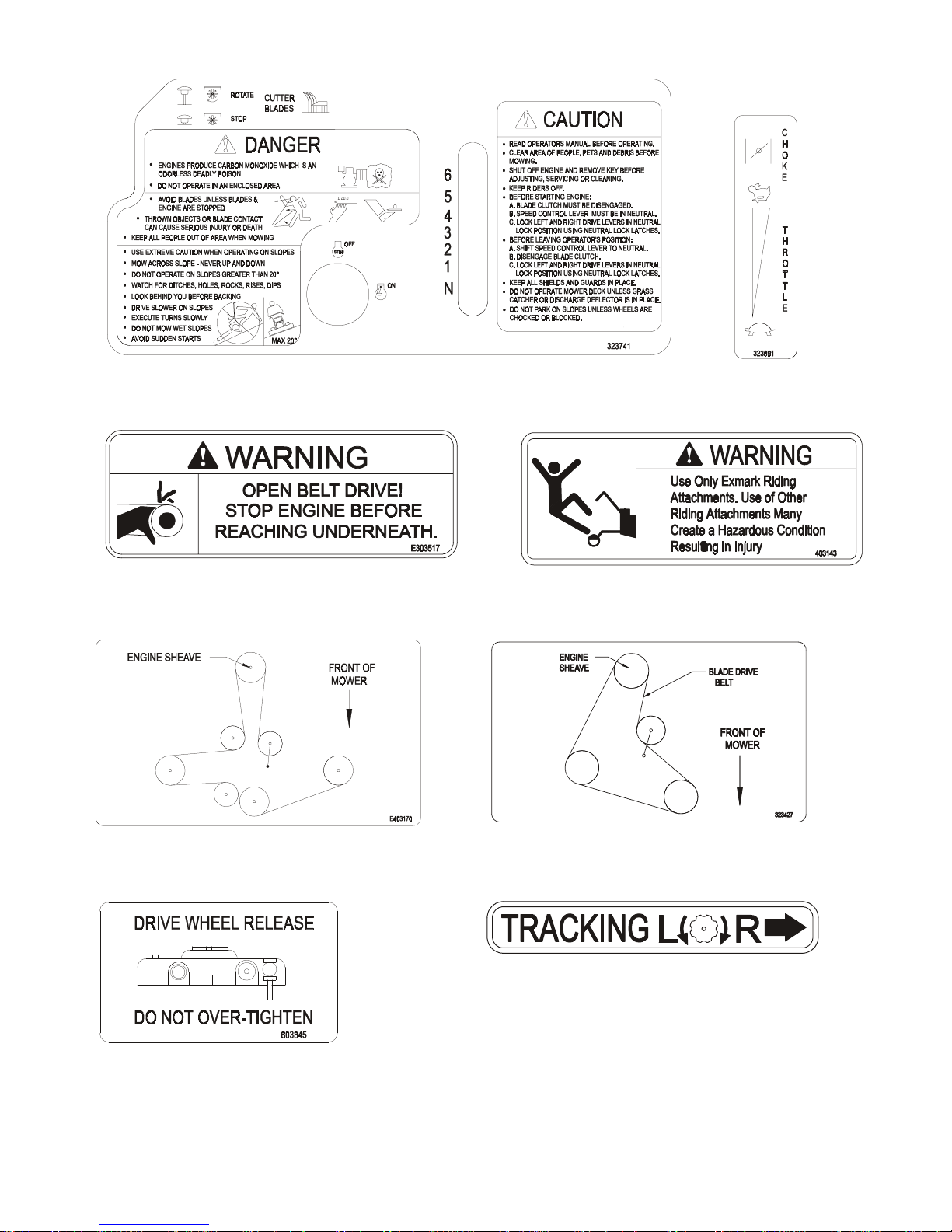
PART NO. 323741
LOCATION: Console
PART NO. 323691
LOCATION: RH Side
of Console
PART NO. 303517
LOCATION: Left Side of Rear
Surface on Engine Deck
PART NO. 403170
LOCATION: 48” Deck
PART NO. 403143
LOCATION: Right Side of Rear
Surface on Engine Deck
PART NO. 323427
LOCATION: 36” Deck
PART NO. 413214
LOCATION: Right Side of Hydro
Control Crank Arm
PART NO. 603845
LOCATION: Rear Center of Top
Surface of Engine Deck
- 6 -
Page 12
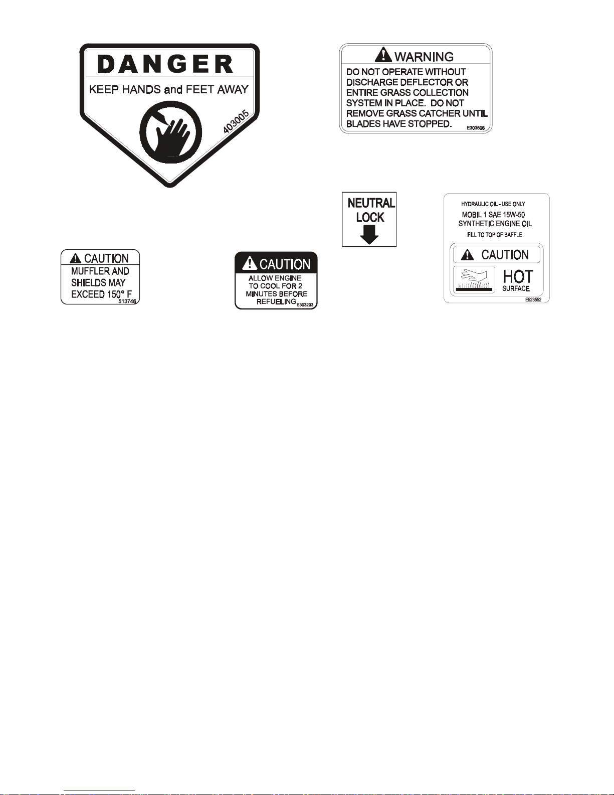
PART NO. 403005
LOCATION: Front Corners of
Mower Deck
PART NO. 303508
LOCATION: On Top Rear Right Hand
Surface of Mower Deck
PART NO. 303102
LOCATION: Upper
Handle
PART NO. 513746
LOCATION: On Engine Blower
Housing Next to Muffler
2. SPECIFICATIONS
2.1 MODEL NUMBER:
Serial Nos. 220,000 & Higher:
2.2 ENGINE
2.2.1 Engine Specifications: See your Engine Owner's Manual.
2.2.2 3600 RPM (No Load).
2.3 FUEL SYSTEM
2.3.1 Capacity: 5.0 gal. ( 18. 9 L.)
2.3.2 Type of Fuel: Regular
using the research method, it should be a 90 oct ane minimum.
2.3.3 Fuel Filter: Replaceable in- line
2.3.4 Fuel Shut-Off Valve: 1/4 turn
2.4 SAFETY INTERLOCK SYSTEM
Operator must have transmission in neutral and blade clut ch disengaged to start
engine. Release of OPC levers will cause the engine to st op if hydro transmission is
not
in neutral and/or blade clutch is
PART NO. 303293
LOCATION: On Top Right
Side of Fuel Tank
VH3615KA; VH4815KA
unleaded
gasoline, 87 octane or higher. I n count r ies
engaged
.
PART NO. 513890
LOCATION: On Top of
Hydraulic Tank
2.5 STEERING/BRAKE CONTROL:
Fingertip drive control levers provide independent speed control, br aking and neutral
to each drive wheel for moving forward or reverse, st opping and power turning.
2.6 TRANSMISSION:
Twin Hydrostatic Drive
2.6.1 Two Hydro Gear BDP-10L series variable displacement pumps independently
coupled to two high efficiency Parker / Ross wheel drive motors .
- 7 -
Page 13

2.6.2 Hydraulic Filter is replaceable cart r idge type.
F)
F)
P/N 513211: 10 microns, 18 psi bypass (Summer use above 32°
P/N 523541: 40 microns, 18 psi bypass (Winter use below 32°
2.6.3 Speed Range: Forward 0 - 6.2 m ph ( 10.0 km/h)
Reverse 0 - 2.2 mph (3.5 km/h)
2.7 WHEEL DRIVE SYSTEM:
Drive wheels are direct coupled to Parker/Ross wheel drive motors with 1.0" (25. 4
mm) tapered shaft.
2.8 TIRES
Drive Front Caster
Size .........................16 x 6.50-8 ........................9 x 3.50-4
Quantity.............................2........................................ 2
Tread.......................Turf Master............................ Smooth
Ply Rating..........................4........................................ 4
Pressure...............14 psi (97 kPa).................22 psi (152 kPa)
2.9 DECK
2.9.1 Cutting Width:
Model 36 in..............................................35.38 in. (89.9 cm)
Model 48 in..............................................47.24 in. (120.0 cm)
2.9.2 Discharge: Right Side
2.9.3 Blade Size:
Model 36 in....................18.00 in. (45.7 cm).............. Qty. 2
Model 48 in....................16.25 in. (41.3 cm).............. Qty. 3
2.9.4 Type of Drive: Manual engagement of belt with over-center lock. Belt tension
is adjustable via turnbuckle.
2.9.5 Blade Brake: W hen t he blade engagement control is move to the disengaged
position a friction brake pad stops the rotation of the blades.
2.9.6 Deck Mounting: Bolted directly to the engine deck.
2.9.7 Cutting Height: Adjusts in 1/4” ( . 63 cm ) increments from 1” (2.5 cm) t o 4 1/ 4”
(10.8 cm).
2.10 DIMENSIONS
2.10.1 Overall Width: 36” 48”
Discharge chute down
Discharge chute up
(Transport only)
2.10.2 Overall Length: 36” 48”
Overall Length
2.10.3 Curb Weight: 36” 48”
Curb Weight
∗
∗ Weights will vary slightly depending on engine option.
2.10.4 Overall Heig ht : 43.2”(109.7 cm)(all units)
2.10.5 Tread Width (to outside of tires):
36” Model....................35.6” (90.4 cm)
48” Model....................39.6” (100.6 cm
46.1” 58.2”
(117.1 cm) (148.0 cm)
36.4” 48.1”
(92.5 cm) (122.2 cm)
78.0” 73.0”
(198.1 cm) (185.4 cm)
433 lbs. 486 lbs.
(196 kg) (220 kg)
- 8 -
Page 14
2.11 TORQUE REQUIREMENTS
BOLT LOCATION TORQUE
Blade/Cutter Housing Spindle Bolt.................................75-80 ft-lbs.
Caster Bracket Mounts..................................................30-35 ft-lbs.
Cutter Deck/Engine Deck Mount....................................30-35 ft-lbs.
Engine Mounting Bolts (Kohler & Kawasaki)..................25-30 ft-lbs.
3. ASSEMBLY INSTRUCTIONS
3.1 Uncrate unit, leaving it on the pallet , place upper handle assembly, fuel tank, and
drive linkages at the rear of the machine. Place casters at the front of unit.
3.2 Place a length of 4" x 4" block bet ween the front of the cutter deck and the pallet.
3.3 Remove the bolt bag from t he top of the fuel tank support .
3.4 Loosen the 5/16" hardware at the two (2) discharg e deflector hinge point s so that
the deflector is snug, but can be m oved up and down freely.
3.5 Refer to Parts Manual to help you identif y and locate par ts and their proper position.
3.6 Install casters to f ront of deck using appropriate har dware from the bolt bag
(eight 3/8 x 3/4" bolts and eight 3/8" whizlock nuts); tightening the lower f our
bolts first, then the top four.
3.7 Apply retaining adhesive “Fel-Pro Prolock Retaining I or Retaining II” or “Loctite
RC 609 or 680” on the two threaded studs from the bolt bag and inst all into the
two left holes underneath fuel tank. Install the fuel tank on top of the fuel tank
support with the studs going throug h t he slot s in the support. Install two 5/16 x
3/4 screws with a 5/16 SAE flatwasher and 5/16 lockwasher into the threaded
holes in the right side of the fuel tank.
flatwasher, then a spring, over each of t he studs and fasten with a 5/16 nyloc
nut. Tighten the 5/16 nylock nut fully than back off a 1/ 2 t urn. This is to allow for
normal fuel expansion and contraction with changes in temperature and fuel
levels.
3.8 Attach the fuel tank hose to the tank fitting and secur e with the clamp provided.
Make sure that fuel hose is not between engine and throttle plate on engine.
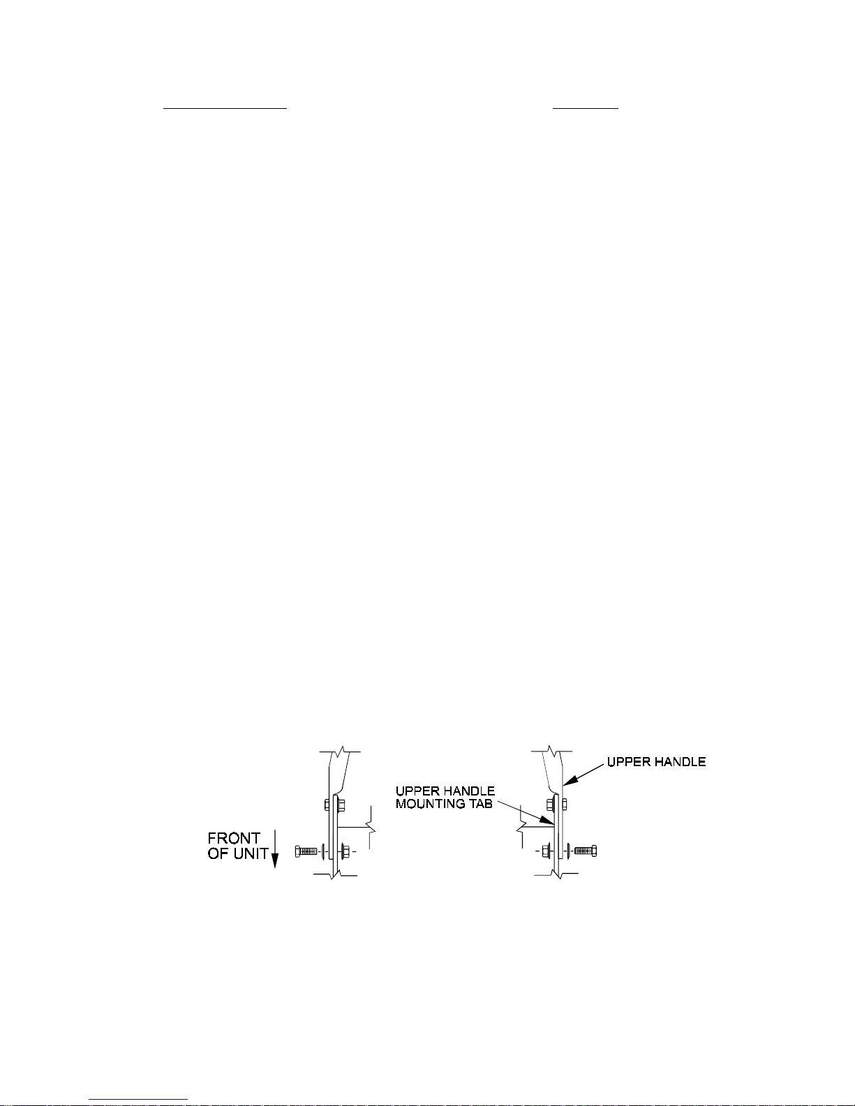
3.9 Position the lower end of the handle assembly on the outsideof the upper rear
section of the fuel tank & handle support.
Install four 3/8-16 x 1" bolts ( with four spring disk washers against the head of each
bolt) from the outside in. Secur e using four 3/8" whizlock nuts on the inside of each
handle support and tighten until the spring disk washers are flat (See Figure 1).
Do not over-tighten
Do not over-tighten
. Place a 5/16” SAE
.
3.10 Route the throttle cable along the right side of the upper handle, under the fuel
tank support, and position the cable on the
Attach throttle cable to engine:
a) Position the throttle control lever (on console) in the full throttle (but not
choke) position. You will feel a detent when the thr ottle lever is
approximately 3/4”from the upper end of the slot (this is full thr ot tle position).
FIG. 1
UPPER HANDLE MOUNTING
left
side of the engine.
- 9 -
Page 15

b) Loosen clamp on engine control plate (See Figure 2). Att ach inner wire of
the throttle cable to the control plate lever and position cable under cable
clamp,
do not
Choke Link
tighten clamp.
Control Plate Lever
Control Alignment Holes
Clamp
Choke Adjusting Screw
Control Cable
FIG 2
15 HP KAWASAKI SPEED CONTROL
(THROTTLE CABLE HOOK-UP)
c) Pull the cable to the right when facing t he control plate until the alignment
holes in control plate lever and control plate line up. A 15/64” (6 mm) drill bit
can be inserted through these two holes to align t hem . Once the holes are
aligned, tighten clamp onto t hr ottle cable.
d) Be sure the
choke adjusting screw just contacts the choke l ever
when the
throttle control is in the full throttle position. Choke link should not move when
throttle control is moved to the full throttle position. Choke must be completely
closed when throttle lever is moved to the full forward “CHOKE” position.
NOTE: For 15 HP Kawasaki engines:
There is not a “STOP” position.
The engine will continue to run when the throttle contr ol is m oved past t he
rear detent. Turn the ignition switch to the “off” position to stop the engine.
e) Secure fuel line to throt tle control cable with a small wire tie from the bolt
bag approximately 2” ahead of filt er to keep fuel line away from hydraulic
lines to prevent vapor lock.
3.11 Install the blade engagement linkage to the bell crank on the
front, left hand
side of the engine deck. I nser t r od through the hole from the outside and fasten
with hairpin cotter from bolt bag.
3.12 Note the square swivel at the end of the hydro control arm linkage. Place the
stud end of the swivel into the hole on the end of the short crank arm located at
the end of the speed control crank ( t op, rear of fuel tank suppor t ) .
Install a 5/16” SAE washer and fasten with a 3/32” x 1/2” cott er pin from bolt bag.
Repeat on opposite side of unit (See Figur e 3) .
HYDRO CONTROL LINKAGE SWIVEL & DRIVE LINKAGE SWIVEL
FIG. 3
- 10 -
Page 16

3.13 Install the speed control rod assembly (linkage with the yoke installed on one end)
into the end of the speed control lever located underneath the center of the
console. Insert the end of the linkage (opposite the yoke) into the end of the speed
control lever from the rig ht hand side and fasten with a hairpin cotter from bolt bag.
3.14 Connect the lower end of the speed control linkage to the speed cont r o l cr ank
located at the top rear of t he fuel tank support. Secure with clevis pin and hairpin
cotter from bolt bag.
3.15 Thread each drive linkage into the threaded swivel. (See Figure 3). Connect the
upper end of each drive linkage to t he dr ive levers. Fast en with a long clevis pin
and hairpin cotter from bolt bag. Be sure the clevis pin is first inserted thr ough
the drive linkage and then throug h t he dr ive lever from the outside before
installing the hairpin cotter ( See Figure 4).
NOTE: There should not be a washer betw een t he neut ral lock latch and
the hairpin cotter.
FIG. 4
DRIVE LINKAGE TO DRIVE LEVER
3.16 Route the long unattached wiring harness lead, up the left hand side of the
handle and connect the two terminals (in any order) to the operat or pr esence
control switch terminals underneath the control console.
Fasten the lead to the handle with two large wire ties from bolt bag, one at the
upper end of the handle next to the console, and one at t he very lower end of t he
handle where it attaches to the fuel tank support.
3.17 The unit is shipped with the muffler installed onto the engine exhaust manifold
but rotated rearward to fit t he cr at e. Loosen the clamp, rotate the muffler ahead
and secure the bracket on the muffler to the bracket on the engine with the
hardware provided. Tighten the clamp.
3.18 Service Engine: Refer to Engine Owner’s Manual.
3.19 Service Hydraulic Oil: The machine is shipped with hydraulic oil filled to the top of
the baffles in the reservoir. Run t he machine for approximately 15 minutes to
allow any extra air to purge out of the hydraulic system. Check hydraulic
reservoir and if necessary fill the reservoir to the appropriate level with Mobil 1
15W-50 synthetic m otor oil.
GREASE UNIT: NOTE:
3.20
UNIT IS NOT GREASED AT THE FACTORY.
Refer to 5.1.13, for locations and grease amounts.
3.21 Follow pre-start instructions as outlined in 4.2.
NOTE: After starting the engine and engaging the hydro drive, if either of
the drive wheels acts sluggish or will not rotate at all, stop engine and
refer to Section 5.1.10 on the Hydraulic System Air Purge procedure.
3.22 Perform any needed adjustments as outlined in the Adjustm ent Section.
- 11 -
Page 17

4. OPERATION INSTRUCTIONS
4.1 Controls
4.1.1 Operator Presence Control (O PC) Levers: Located on the upper handle
assembly directly above the handle grips.
the OPC system senses that the operator is in the normal operator's
position. When the levers are released, the OPC system senses that the
operator has moved from the normal operating position
engine if either the speed contr ol lever is
blade clutch is engaged
4.1.2 Speed Control Lever: Located in middle of control console, it controls the
maximum forward speed and is infinitely variable from neutral (0 mph) to 6.2
mph.
4.1.3 Drive Levers: Located on each side of the upper handle assembly directly
below the handle grips (See Figure 5). T hese levers individually control the
speed and direction of each drive wheel. When the speed control lever is
moved out of the neutral position and the neut ral lock latches are moved
into the drive position, as shown in Figure 5, and the drive levers are released,
the drive wheels are engaged in the forward direction.
Squeezing the left hand and/or r ight hand lever causes the left hand and/or right
hand drive wheel respectively to slow down, stop, or reverse, depending on how
far each drive lever is "squeezed". Squeezing the drive levers beyond the
neutral position causes the drive wheels to engage in the reverse direction
regardless of the position of the neutral lock latches and the speed contr ol lever.
4.1.4 Neutral Lock Latch: Located directly above the drive levers. T hese lat c hes allow
the operator to lock the dr ive levers in a "neut r al" position where neither of the
drive wheels are engaged in either a forward or reverse direction (See Figure 5).
When these levers are depressed,
and will kill the
not in the neutral
position or the
.
DRIVE LEVER, NEUTRAL LOCK LATCH OPERATION
4.1.5 Blade Engagement: The “push/ pull” blade engagement knob is located on the
left side of the contr ol console. To engage the blades, the knob must be pulled
toward the operator until the turnbuck le ( attached to the blade engagement
idler) locks over-center. To disengage the blades, push the knob down until the
assist arm contacts the pin on the deck.
4.1.6 Throttle-Choke Contr ol: The throttle-choke control lever is located on t h e
control console right side. Choke aids in st ar t ing a cold engine. The choke
control is a part of the thr ot tle control and activates by moving the throttle
control lever to the full forward position. You will notice a detent at the “full
throttle” position (approximately 3/4” from top of slot) continue pushing forward
into the “choke” position.
FIG. 5
- 12 -
Page 18

Once the engine has started, move the t hr ot tle control lever to the midway
point and allow the engine to warm-up before g oing to full throttle.
4.1.7 “Off-Run” Switch: Located on the console. Turn key to the “Run” position to
allow the engine to be started. Turn key to the “Off” posit ion t o shut engine off.
4.1.8 Fuel Shut-Off Valve: I nstalled in the fuel line midway between the tank and
engine. The fuel shut-off valve is used to shut off the flow of fuel when parking
inside a building, during transport at ion t o and from the job sites, and when the
machine will not be used for a few days.
Rotate valve 1/4 turn clockwise to shut fuel off.
Rotate valve 1/4 turn counter-clockwise to turn fuel on.
4.1.9 Drive Wheel Release Valves: Located on the top r ear cor ner of the hydrostatic
pumps. Drive wheel release valves are used to release the hydro-static drive
system to allow the machine to be moved by hand without the engine running.
Turn valves one-half turn counterclockwise to release the drive system.
Turn clockwise to reset the drive system.
4.1.10 Cold Start Kit: Located on the right hand side of engine deck, below and
slightly ahead of the hydro control shield. T he cold st art kit is used to ease the
starting of the unit in cold weather or when the unit has not been operated for a
period of time. The cold star t kit moves the idler pulley away from the pump
belt, releasing the tension on the belt which allows the engine t o t urn over with
less resistance. See Section 4.3.2.
4.1.11 Tracking Adjustment Knob: Located on the right - hand side of the rear of the
fuel tank support. Can be adj usted so that machine will “track” straight ahead
with drive levers released.
Do Not over-tighten.
4.2 Pre-Start
POTENTIAL HAZARD
♦ In certain conditions gasoline is extremely flammable
and highly explosive.
WHAT CAN HAPPEN
♦ A fire or explosion from gasoline can bur n you, ot hers,
and cause property damage.
HOW TO AVOID THE HAZARD
♦ DO NOT smoke while refueling , and stay away from an
open flame or where gasoline fumes m ay be ignited by
spark.
♦ Refuel only in a well ventilated area, or refuel outdoor s.
♦ Store gasoline in an approved container and keep it out
of the reach of children.
♦ Add fuel before start ing the engine. Never remove the
cap of the fuel tank or add fuel when engine is running
or when the engine is hot.
♦ Never fill the fuel tank so that the gasoline level rises
above a level that is 1/2” below the bottom of the filler
neck to allow for gasoline expansion and prevent fuel
spillage.
♦ If fuel is spilled, DO NOT attempt to start the engine.
Move away from the area of the spill and avoid creating
any source of ignition until fuel vapors have dissipated.
DANGER
- 13 -
Page 19

4.2.1 Fill fuel tank. For best r esults use only clean fresh regular grade
gasoline with an octane rating of 87 or higher. Regular grade leaded gasoline
may also be used; however, combustion chamber and cylinder head will
require more fr equent service. See Engine Owner's Manual.
Do not add oil to gasoline.
unleaded
POTENTIAL HAZARD
♦ In certain conditions gasoline is extremely flammable
and highly explosive.
WHAT CAN HAPPEN
♦ A static charge can ignite g asoline vapors. A fire or
explosion from gasoline can burn you, others, and
cause property damage.
HOW TO AVOID THE HAZARD
♦ Purchase and store gasoline only in an approved
container.
♦ Always place gasoline containers on the ground away
from your vehicle before f illing.
♦ Do not fill gasoline containers inside a vehicle or on a
truck or trailer bed because inter ior car pets or plastic
truck bed liners may insulate the container and slow
the loss of any static charge.
♦ When practical, r emove gas-powered equipment from
the truck or trailer and refuel the equipment with its
wheels on the ground.
♦ If this is not possible, then refuel such equipment on a
truck or trailer from a portable container, rather t han
from a gasoline dispenser nozzle.
♦ If a gasoline dispenser nozzle must be used, keep the
nozzle in contact with the rim of the fuel tank or
container opening at all times until fueling is complete.
DANGER
4.2.2 Refer to Maintenance and Adjustment Section 5 and perform all of the
necessary inspection and maintenance steps.
4.2.3 Familiarize yourself with the controls and operation of unit . See Controls
section 4.1 and Operating Instructions section 4.3.
4.3 OPERATING INSTRUCTIONS
4.3.1 Refer to Engine Owner’s Manual for detailed operat ing instructions regarding
the engine.
4.3.2 Starting Engine: Operat or m ust have
transmission in neutral
Open
fuel shut-off valve.
blade drive disengaged
.
- 14 -
and
Page 20

POTENTIAL HAZARD
♦ Engine exhaust contains carbon monoxide, which is
an odorless deadly poison.
WHAT CAN HAPPEN
♦ Carbon monoxide can kill you and is also known to the
State of California t o cause birth defects.
HOW TO AVOID THE HAZARD
♦ Do not run engine indoors or in a small confined area
where dangerous carbon monoxide fumes can collect.
NOTE: A cold weather starting kit has been added for ease of starting in
either cold weather or when the unit has not been run for a period of time.
To use cold start kit:
a) Place shifter in neutral position.
b) Pull split ring straight out the side of t he unit, and hook the ring over
the lower front hydro control shield bolt.
c) Start eng ine. Refer to the following guidelines for further starting
suggestions.
To engage pump drive (unhook cold st ar t kit)
a) Pull chain straight out from the side of the unit until the split ring can
be removed from the bolt.
SLOWLY
On a cold engine, place the thrott le in t he full forward “Choke” position. Turn
the key switch to the “Run” position. Pull recoil rope t o st ar t engine.
With a cold eng ine, gradually return choke to the full throttle position after t h e
engine starts and warms up.
NOTE: Kawasaki engines generally need to be “choked” even when
warm.
release tension on chain.
WARNING
NOTE: It is helpful to have the left and right neutral lock latches applied
when starting the engine, See Controls Section 4.1.
4.3.3 Stopping Engine: Disengage blade dr ive, shift transmission to neutral and lock
the drive levers in neutral. Move throttle to the “ Slow” position. Allow engine t o
idle for 30 seconds to allow cool down. Move the throttle to the midway
position. Turn the key to the “Off” position and remo ve the key.
4.3.4 Drive Lever/Neutral Lock Latch Operation: To lock the drive levers in neutral,
squeeze the drive levers back to the neutral position.
Do Not
(
wheels to go into full reverse direct ion) Place t hum bs on the upper portion of
the neutral lock latches and move them t o t he r ear. Release drive levers (See
Figure 7).
squeeze the drive levers all the way back as this will cause the drive
- 15 -
Page 21

POTENTIAL HAZARD
♦ If the neutral lock latches are not completely engaged the
drive levers could unexpectedly slip into the forward drive
position.
WHAT CAN HAPPEN
♦ If the drive levers slip into the drive position, the unit could
lurch forward and cause injury or property damage.
HOW TO AVOID THE HAZARD
♦ Be sure the pins protruding throug h the slots of each neutral
lock latch are completely engaged in t he r ear slot of each
latch.
To place the drive levers in the drive position, fir m ly hold the drive levers, place
thumbs on the upper portion of the neutral lock latches and move them forward
to release drive levers.
4.3.5 Drive Wheel Engagement/Turning: With drive levers located in neutral, shift
speed control lever to desired forward speed. Slowly squeeze and hold both
drive levers in the neutral position and move both neutral lock lat c hes from the
neutral lock position.
will cause the drive wheels to be engaged in the reverse direction.
For straight ahead motion, sm oot hly release bot h dr ive levers to engage drive
wheels. Squeeze the right hand drive lever to turn right and the left hand drive
lever to turn left.
To make a “zero turn”, squeeze either the left hand or the right hand drive lever
back into the reverse position while the opposite drive lever is in a forward
position at an equal but opposite speed.
To back up, squeeze both drive levers into the reverse posit ion.
For smooth operation of this m achine, avoid quick, jerky movements of the
drive levers. Move the drive levers smoothly and deliberately.
4.3.6 To Stop: Squeeze drive levers back to the neut r a l posit ion. Move neutral lock
latches into the neutral lock position and r elease drive levers. Move the speed
control lever to the neutral position.
4.3.7 Blade Engagem ent :
Slowly
Do Not
CAUTION
carefully
and
squeeze both drive levers all the way back, this
release the drive levers.
POTENTIAL HAZARD
♦ The rotating blades under the mower deck are
dangerous.
WHAT CAN HAPPEN
♦ Blade contact can cause serious injury or kill you.
HOW TO AVOID THE HAZARD
♦ DO NOT put hands or feet under t he mower or mower
deck when the blades are engaged.
Be sure that all persons are clear of mo wer deck and dischar ge area before
engaging the blades. Set t hrottle to “midway” position. Pull the blade
engagement knob up and rear ward to engage blades. Accelerate to full thr ottle
to begin mowing (See Section 4.1.5).
DANGER
- 16 -
Page 22

4.3.8 Blade Disengagement : Push forward and down completely on the engagement
knob to disengage the blades (See Section 4.1.5).
4.4 TRANSPORTING
POTENTIAL HAZARD
♦ Loading the mower onto a trailer without strong
enough or properly supported ramps could be
dangerous.
WHAT CAN HAPPEN
♦ The ramps could collapse causing the unit to fall,
which could cause injury.
HOW TO AVOID THE HAZARD
♦ Use proper ramps that are secured to the t ruck or
trailer.
♦ Keep feet and legs out f r om under the unit when
loading and unloading.
♦ If necessary, use assistance when loading.
Use a heavy duty trailer to transport the machine. Engage neutral lock latches
and block wheels. Securely fasten the machine to the trailer with straps,
chains, cables or ropes. Use a safety chain and be sure that the trailer has all
necessary lighting and marking as required by law.
WARNING
5. MAINTENANCE & ADJUSTMENTS
WARNING
POTENTIAL HAZARD
♦ If you leave the key in the ignition switch, someone
could start the engine.
WHAT CAN HAPPEN
♦ Accidental starting of the engine could seriously injure
you or other bystanders.
HOW TO AVOID THE HAZARD
♦ Remove the key from the ig nit ion switch and pull the
wire(s) off the spark plug(s) before you do any
maintenance. Also push the wire(s) aside so it does
not accidentally contact the spark plug( s) .
WARNING
POTENTIAL HAZARD
♦ The engine can become very hot.
WHAT CAN HAPPEN
♦ Touching a hot engine can cause severe burns.
HOW TO AVOID THE HAZARD
♦ Allow the engine to cool completely before service or
making repairs around the eng ine area.
- 17 -
Page 23

5.1 PERIODIC MAINTENANCE
5.1.1 Check engine oil level.
Service Interval:
a) Make sure engine is stopped and on a level surface.
b) Check with engine cool.
c) Clean area around dipstick. Remove dipstick and wipe oil off. Reinser t
the dipstick (
level.
d) If the oil level is low, add oil as specified in the Eng ine O wner’s Manual to
bring the oil level up to the “F” mark on the dipstick.
DO NOT OVERFILL
IMPORTANT:
5.1.2 Clean engine air cooling system.
Service Interval:
a) Stop engine and remove spark plug wire(s) .
b) Clean all debris from engine air intake screen and from around engine
shrouding.
5.1.3 Clean grass build-up under deck and check mower blades.
Service Interval:
See Engine Owner's Manual
DO NOT
DO NOT
mark or over the “F” mark.
See Engine Owner's Manual
Daily
screw into place). Remove dipstick and check oil
.
operate the engine with oil level below the “L”
CAUTION
POTENTIAL HAZARD
♦ Raising the mower deck for service or m aint enance
relying solely on mechanical or hydraulic jacks could
be dangerous.
WHAT CAN HAPPEN
♦ The mechanical or hydraulic jacks may not be enough
support or may misfunction allowing the unit to fall,
which could cause injury.
HOW TO AVOID THE HAZARD
♦ DO NOT rely solely on mechanical or hydraulic jacks
for support. Use adequate jack stands or equivalent
support.
a) Disengage blade clutch.
b) Stop engine and remove spark plug wire(s) .
c) Raise deck and block up using proper safety precaut ions.
d) Clean out any grass build-up from under side of deck and in deck
discharge chute.
e) Inspect blades and sharpen or replace as required.
f) If blade removal is necessary, be careful for the sharp cutting edges of
the blades.
g) Re-install the blades (if they were removed) and tor que blade bolts to 75-
80 ft.lbs. Be sure the spring disk washer cone is installed toward the bolt
head (See Figure 6).
- 18 -
Page 24

h) Remove jack stands (or equivalent support ) and lower deck t o ground.
BLADE BOLT INSTALLATION
5.1.4 Check safet y interlock system.
Service Interval:
Daily
a) For your safety, your Exmark mower is equipped with Operat or Presence
Controls (OPC). When either the mower blades are engaged, or the
speed control lever is not in neutral and both hands are removed from the
handles, the mower engine
b) Check OPC circuits. Clear t he area. Run engine at one-third throttle, then
with drive levers and neutral lock latches in
the speed control lever out of neutral and r elease OPC levers -
MUST stop.
Again, run engine at one-thir d throttle, move the speed control lever to
neutral
, engage blade clutch and releaseOPC levers -
stop.
c) If machine does not pass any of these tests,
your authorized
EXMARK SERVICE DEALER.
FIG. 6
MUST stop.
neutral lock position
engine
engine MUST
DO NOT
operate. Contact
, move
IMPORTANT: It is essential that all Operator Safety Mechanisms be
connected and in proper operating condition prior to the use of the
mower.
5.1.5 Check for loose har dware.
Service Interval:
Daily
a) Stop engine and remove spark plug wire(s) .
b) Visually inspect machine for any loose hardware or any other possible
problem. Tighten hardware or correct the problem before operating.
5.1.6 Service pre-cleaner element and air cleaner .
Service Interval:
See Engine Owner's Manual
5.1.7 Change engine oil.
Service Interval:
See Engine Owner's Manual
NOTE: Change oil after first five (5) hours of operat ion. Follow engine
manufacturers recommendations for future oil changes.
a) Disengage blade clutch.
b) Stop engine and remove spark plug wire(s) .
c) Drain oil while engine is warm from operation.
- 19 -
Page 25

d) Remove the oil drain plug from t he r ight hand side of the engine. Allow oil
to drain, then replace drain plug.
e) Replace the oil filter as per Eng ine O wner's Manual. Clean around oil
filter and unscrew filter to remove. Before reinstalling new f ilter, apply a
thin coating of oil on the surface of the rubber seal. Tur n filter clockwise
until rubber seal contacts the f ilt er adapter then tighten filter an addit ional
2/3 to 3/4 turn.
f) Clean around oil fill cap and remove cap. Fill to the specified capacity and
replace cap. Use oil as specified in Engine Owners Manual.
overfill.
g) Start the engine and check for leaks. Stop engine and recheck oil levels.
5.1.8 Check hydraulic oil level.
Service Interval:
40 hr.
a) Stop engine.
b) Clean area around hydraulic reservoir cap and remove cap. Oil level
should be to the top of the baf fle inside the tank. If not , add oil.
Do not
WARNING
POTENTIAL HAZARD
♦ Hydraulic fluid escaping under pressure can penetrat e
skin and cause injury.
WHAT CAN HAPPEN
♦ Fluid accidentally injected into the skin must be
surgically removed within a few hours by a doctor
familiar with this form of injury or gangrene ma y result .
HOW TO AVOID THE HAZARD
♦ Make sure all hydraulic fluid hoses and lines are in
good condition an all hydraulic connections and fittings
are tight before applying pressure to hydraulic system.
♦ Keep body and hands away from pinhole leaks or
nozzles that eject high pressure hydraulic fluid.
♦ Use cardboard or paper to find hydraulic leaks.
♦ Safely relieve all pressure in the hydraulic system
before performing any work on t he hydraulic system.
5.1.9 Change hydraulic system filter.
Service Interval:
After First 250 hrs, then yearly thereafter.
Note: Use Exmark Part No. 513211 for Sum m er use above 32°
Part No. 523541 for Winter use below 32°
Specifications.)
a) Place unit on a level surface, stop engine and rem ove spark plug wire(s).
b) Carefully clean area around filt er . It is important that no dirt or
contamination enters the hydraulic system.
c) Unscrew filter to remove and allow oil to drain from reser voir.
IMPORTANT:
Before re-installing new filter, fill it completely with Mobil 1
15W-50 and apply a thin coat of oil on the surface of the r ubber seal. Turn
filter clockwise until rubber seal contact s t he filter adapter. Do not tigh t en yet.
d) Fill reservoir as stated in Section 5.1.8.
F (0° C)and use
F (0° C). (Refer to 2.6.2 for Filter
- 20 -
Page 26

e) Loosen filter 1/2 turn and allow a small amount of oil to leak from t he oil
filter (this allows air to be purged from the oil filter and supply hose from
the hydraulic reservoir). Turn f ilter clockwise until rubber seal contacts the
filter adapter. T hen t ighten the filter an additional 2/3 to 3/4 turn.
f) Raise the rear of the machine up onto jack stands high enough to raise
the drive wheels off of the g r ound. Run machine to allow any other air to
be purged from the hydraulic system and recheck the oil level.
g) If either drive wheel does not rotate, one or bot h of the charge pumps
(located on the top of the main pump as shown in Figur e 7) m ay have lost
their “prime”. Ref er t o Section 5.1.10.
DO NOT
h)
change hydraulic system oil (except what can be drained when
changing filter) unless it is felt t hat oil has been contaminated.
oil unnecessarily could damage the hydraulic system by introducing
contaminates into the system.
5.1.10 Hydraulic system air purge pr ocedur e.
Air must be purged from the hydraulic system when any hydraulic components,
including oil filter, are r em oved or any of the hydraulic lines are disconnected.
The critical area for purging air from the hydraulic system is between the oil
reservoir and each charge pump located on the top of each variable
displacement pump. (See Figure 7).
Air in other parts of the hydraulic system will be purg ed through normal
operation once the charge pump is “primed” .
a) Stop engine. Raise the rear of the machine up onto jack stands high
enough to raise the drive wheels off the ground.
b) Check oil level as stated in Section 5.1.8.
c) Start engine an move throttle control ahead to f ull throttle position. Move
the speed control lever to the middle speed position and place the drive
levers into the “drive” position.
If either drive wheel does not rotate, it is possible t o assist t he purging of
the charge pump by carefully rotating the tire in t he forward direction.
NOTE: It is necessary to lightly touch the charge pump cap with your
hand to check the pump temperature. If the cap is too hot t o t ouch, turn
off engine. The pumps may be damaged if the pump becomes too hot.
If either drive wheel still does not rotate cont inue with step ( d).
d) Thoroughly clean the area around each of the charge pump housings.
Changing
FIG. 7
CHARGE PUMP LOCATION
- 21 -
Page 27

e) To “prime” charge pump, loosen two hex socket head capscrews (shown
in Figure 7)
1-1/2 turns only.
charge pump housing upward and wait for a steady flow of oil t o flow out
from under housing.
Note: Hydraulic reservoir can be pressurized to up to 5 psi to speed this
process.
f) If either drive wheel still does not rotate, stop and repeat steps (d)
through (e) above for the r espect ive pump. If wheels rotate slowly, the
system may prime after additional running. Check oil level as stated in
Section 5.1.8.
g) Allow unit to run several minutes after the char ge pumps are “primed”
with drive system in the full speed position. Check oil level as stated in
Section 5.1.8.
h) Check hydro drive linkage adjustment as stated in Section 5.2.9.
5.1.11 Check tire pressur es.
Service Interval:
40 hrs.
a) Stop engine and remove spark plug wire(s) . Check air pressure in tires;
recommended tire pressure is: rear,
b) Inflate tires to pressures st at ed above. Measure circumference of each
drive tire. Adjust tire pressures within above range to tr y to m ake the
circumferences match as closely as possible.
NOTE: Front caster tires have permanent tire sealant install ed.
5.1.12 Inspect Belt wear.
Service Interval:
40 hrs.
a) Stop engine and remove spark plug wire(s) .
b) Remove cutter deck belt shield to check m ower prim ar y and secondary
(48” decks) belt condition.
c) Look under engine deck to check the pump drive belt condition.
d) Check all idler arms to be sure t hey pivot freely. Disassemble, clean and
grease pivot bushings if necessary.
5.1.13 Lubrication
Service Interval:
Refer to Chart.
a) Stop engine and remove spark plug wire(s) .
b) Lubricate fittings with one to t wo pumps of SAE No. 2 multi-purpose gun
grease
.
Refer to the following chart for fitting locations and lubricat ion schedule.
Make sure engine is not running.
Retighten capscrews
12 -16 psi; pneumatic casters, 22 psi.
Lift
. Do this for both pumps.
FITTING
LOCATIONS
1. Caster Wheel Bearings 12 2 2 Daily
2. Caster Pivots 2 2 2 Daily
3. Blade Engagement Lower Bellcrank 1 1 1 Monthly
4. Idler Pivot (Pump Drive) 2 1 1 Week ly
5. Pump Control Bearings 2 2 2 Weekly
6. Cutter Deck Idler Pivot 2 1 1 Weekly
GREASE LUBRICATION CHART
INITIAL
PUMPS
- 22 -
QUANTITY
36” 48”
SERVICE
INTERVAL
Page 28

No. 4 Idler Pivot (Pump Drive)
Located Under Engine Deck
No. 4 & 6 (Idler Pivots)
Disassemble and grease once a
month under a “No Load” condition.
c) Lubricate pivot points with a spray penetrating lubricant as directed
below.
SPRAY LUBRICANT CHART
PIVOT POINT
NO. OF PLACES
36” 48”
1. Blade Engagement Upper Bellcrank 2 2 Weekly
5.1.14 Check spark plugs.
Service Interval:
160 hrs.
a) Remove spark plugs, check condition and adj ust plug gap or replace with
new plugs. See Engine Owner's Manual.
5.1.15 Remove engine shrouds and clean cooling fins.
Service Interval:
See Engine Owner's Manual
a) Stop engine and remove spark plug wire(s) .
b) Remove cooling shrouds from eng ine and clean cooling fins. Also clean
dust, dirt and oil from external sur faces of engine which can cause
improper cooling.
c) Make sur e cooling shrouds are properly reinstalled. Operating t he engine
without cooling shrouds will cause engine damage due to overheating.
5.1.16 Change fuel filter.
Service Interval:
As Required
a) A fuel filter is inst alled in the fuel line between the fuel tank and the
engine. Replace when necessary.
5.1.17 Refer to Engine Operators Manual for detailed maintenance r egarding the
engine.
5.1.18 Wheel hub - slott ed nut t orque specification.
When tig ht ening the slotted nut on the wheel motor tapered shaf t:
a) Torque the slotted nut to 100 ft. lbs.
b) Further tighten the nut until the next set of slots line up with the cross
hole in the shaft.
c) Replace cotter pin.
d) To aid in wheel hub removal, it is recommended that an
compound
is used on the tapered shaft of t he wheel motor .
5.1.19 Thread locking adhesives such as “Loctite 242” or “Fel-Pro, Pro-Lock NutType” are used on the following fasteners:
a) All belt drive pulley setscrews.
b) Square head setscrews on Hydro pump control arm.
- 23 -
SERVICE
INTERVAL
antisieze
Page 29

c) OPC lever setscrews.
d) Shoulder bolts in ends of speed control crank.
e) Between the fuel tank studs and the fuel tanks.
f) Between the shifter lever and the knob.
Adhesives such as “Loctite RC/609 or RC/680” or “Fel-Pr o Pr o- Lock Retaining
I or Retaining II” are used on the following:
a) OPC lever hubs and cross-shaft
NOTE: Care must be used
hub, to the cross shaft whi ch could cause binding of the OPC levers and
erratic operation.
b) Transmission drive pulley on the engine PTO shaft.
5.1.20 An anti-seize compound is used on the following locations:
a) On the blade drive pulley hub, located on the engine PTO shaft (this
allows for ease of removal of t he pulley).
b) Between the cutter housing spindles and the sheaves.
5.1.21 Dielectric grease is used on all blade type electrical connections to prevent
corrosion and loss of contact.
5.2 ADJUSTMENTS
not
to bond the bearing, next to each OPC
WARNING
POTENTIAL HAZARD
♦ If you leave the key in the ignition switch, someone
could start the engine.
WHAT CAN HAPPEN
♦ Accidental starting of the engine could seriously injure
you or other bystanders.
HOW TO AVOID THE HAZARD
♦ Remove the key from the ig nit ion switch and pull the
wire(s) off the spark plug(s) before you do any
maintenance. Also push the wire(s) aside so it does
not accidentally contact the spark plug( s) .
WARNING
POTENTIAL HAZARD
♦ The engine can become very hot.
WHAT CAN HAPPEN
♦ Touching a hot engine can cause severe burns.
HOW TO AVOID THE HAZARD
♦ Allow the engine to cool completely before service or
making repairs around the eng ine area.
- 24 -
Page 30

5.2.1 Blade Spacers:
Blades may be adjusted for cutting heig ht by using the four 1/4" spacers found
on the blade spindle bolts (factory setting is two above and two below). This
allows a 1" range in 1/4" increments of cut ting height in any axle position. The
same number of blade spacers must be used on all blades to achieve a level
cut (two above and two below, one above and three below, etc.).
For the best cut and discharge a minimum of two spacers should be placed
between the blade and spindle shaft. The highest quality cut can be achieved
with all four spacers between the blade and the spindle shaft.
If the mulching k it is inst alled, the highest quality cut can be obtained with 3
spacers between the blade and spindle (minimum is 1 for a g ood cut).
If you need to cut higher or lower than what the spacer s will allow, it will be
necessary to adjust the rear axle height and caster posit ion. See Section 5.2.2
below.
5.2.2 Axle height and caster spacer position:
Desired cutting height rang e can be obt ained by adjust ing the rear axle and
placing caster spacers above or below the caster arm (See Figur e 8) .
To adjust rear axle:
a) Stop engine and remove spark plug wire(s) .
b) Raise the rear of the m achine up onto jack stands and remove the drive
wheels.
CAUTION
POTENTIAL HAZARD
♦ Raising the mower deck for service or m aint enance
relying solely on mechanical or hydraulic jacks could
be dangerous.
WHAT CAN HAPPEN
♦ The mechanical or hydraulic jacks may not be enough
support or may misfunction allowing the unit to fall,
which could cause injury.
HOW TO AVOID THE HAZARD
♦ DO NOT rely solely on mechanical or hydraulic jacks
for support. Use adequate jack stands or equivalent
support.
c) Loosen but do not remove the
mounting bracket,
d) Remove the bottom sets of hardware for each brack et .
e) Reposition the mounting bracket to the desir ed height and reinstall
the bottom hardware.
f) Tighten all hardware and remount drive wheels.
DO NOT
top
two bolts on each hydraulic motor
remove (See Figure 8).
- 25 -
Page 31

FIG. 8
AXLE and CASTER HEIGHT ADJUSTMENT
Refer to the following chart to properly adjust desired cutting height .
CUTTING HEIGHT ADJUSTMENT (1" to 4 1/4")
AXLE
POSITION
(FIG. 9)
NO. OF SPACERS
BELOW
CASTER
1/2" 3/16"
NUMBER OF 1/4” BLADE SPACERS
BELOW
SPINDLE
4 3 2 1 0
A 0 0 1" 1 1/4" 1 1/2" 1 3/4" 2"
A 0 1 1 1/8" 1 3/8" 1 5/8" 1 7/8" 2 1/8"
A 1 0 1 3/8" 1 5/8" 1 7/8" 2 1/8" 2 3/8"
B 0 1 1 3/8" 1 5/8" 1 7/8" 2 1/8" 2 3/8"
B 1 0 1 5/8" 1 7/8" 2 1/8" 2 3/8" 2 5/8"
B 1 1 1 3/4" 2" 2 1/4" 2 1/2" 2 3/4"
B 2 0 2" 2 1/4" 2 1/2" 2 3/4" 3"
C 1 1 1 7/8" 2 1/8" 2 3/8" 2 5/8" 2 7/8"
C 2 0 2 1/8" 2 3/8" 2 5/8" 2 7/8" 3 1/8"
C 2 1 2 1/4" 2 1/2" 2 3/4" 3" 3 1/4"
C 3 0 2 1/2" 2 3/4" 3" 3 1/4" 3 1/2"
D 2 1 2 3/8" 2 5/8" 2 7/8" 3 1/8" 3 3/8"
D 3 0 2 1/2" 2 3/4" 3" 3 1/4" 3 1/2"
D 3 1 2 3/4" 3" 3 1/4" 3 1/2" 3 3/4"
D 4 0 3" 3 1/4" 3 1/2" 3 3/4" 4"
E 3 1 2 7/8" 3 1/8" 3 3/8" 3 5/8" 3 7/8"
E 4 0 3 1/8" 3 3/8" 3 5/8" 3 7/8" 4 1/8"
E 4 1 3 1/4" 3 1/2" 3 3/4" 4" 4 1/4"
IMPORTANT: To achieve the highest quality of cut, blades should be level wi t h the
ground, or tipped slightly down at t he f r ont .
5.2.3 Blade engagement Linkage: Located between the blade engagement bellcrank
and blade engagement assist arm beneath the front, left hand corner of the
engine deck.
a) Stop engine and remove spark plug wire(s).
- 26 -
Page 32

b) With blade drive engaged (lever pulled up, adjust the linkage length to
where the lower end of the bellcrank just clears the axle support gusset
(See Figure 9). Make sure the assist arm is against the rear assist arm
stop on the deck (See Figure 10). Push the lever down to the disengaged
position. The assist arm should contact t he front assist arm stop on the
deck. If it does not cont act , readjust so that the bellcrank is closer t o t he
gusset.
BLADE ENGAGEMENT LINKAGE
5.2.4 Blade Safety Switch:
a) Stop engine and remove spark plug wire(s).
b) W it h blades disengaged and the bellcrank touching the r ear of the slot in
the engine deck, adjust the blade safety switch mounting bracket (if
needed) until the bellcrank depresses the plung er by 1/4” .
c) Be sure the bellcrank
the switch could occur.
d) Retighten switch blade mounting brack e t .
5.2.5 Engine to Cutter Deck Belt:
a) Stop engine and remove spark plug wire(s) .
b) Check belt guides under rear eng ine and front mower deck to see that
they are properly set (See Section 5.2.6).
c) Belt must be tight enough so it does not slip during heavy loads while
cutting grass. Over-tensioning will reduce belt and spindle bearing life. To
adjust belt tension, loosen the 5/16" whizlock nut on tur nbuckle and
rotate the turn buckle; rot at e turnbuckle toward rear of mower to tighten,
and toward front of mower to loosen belt t ension (See Figure 10).
For 48” Decks: If t her e is no adjustment left in the turnbuckle and the
belt is still loose, the rear idler pulley can be repositioned in the front hole
(See Figure 10). The belt g uide located next to the pulley must also be
repositioned in the front hole when the pulley is moved. The turnbuckle
will need to be readjusted.
Check belt tension after t he first hour of operation and at least twice
during the first 24 hours of operation. Adjust as necessary.
Note: After readjust ing the belt tension check the belt guide adj ust m ent
Section 5.2.7 and blade brake adjustm ent Section 5.2.6.
FIG. 9
DOES NOT
touch the switch body or damage to
- 27 -
Page 33

CUTTER DECK BELT ADJUSTMENT
e) Proper belt tension will require about 10 lbs. side pull on belt , halfway
between pulleys, to deflect belt 1/2”. ( See Figure 10, Point A).
5.2.6 Blade Brake Adjustment:
a) Stop engine and remove spark plug wire(s) .
b) Disengage the blades.
c) Make sure the blade brake pad r est s against the sheave. Adjust the spring
mounting bolts to properly align t he pad on the sheave. See Figure 11.
d) Check the distance between the spacer and the nut at t he end of the
blade brake rod. The distance should be between 1/8” and 3/ 16” . See
figure 11.
e) Engag e t he blade control and check to make sure the blade brake pad
clears the sheave.
FIG. 10
5.2.7 Belt Guide Adjust m ent :
a) Stop engine and remove spark plug wire(s) .
b) Engage the blade drive belt.
c) Check belt guides under the engine deck for proper adjustment (See
Figures 12 and 13). Adjust as necessary.
FIG. 11
BLADE BRAKE ADJUSTMENT
- 28 -
Page 34

Note: These drawings are viewed from underneath the engine deck
FIG. 12 FIG. 13
36" BELT GUIDE LOCATION 48" BELT GUIDE LOCATION
5.2.8 Pump Drive Belt Tension Adj ustment:
No adjustment necessary
.
5.2.9 Hydro Drive Linkage Adjustment:
a) Adjust Speed Control Linkage and neutral safety switch
1. Move the speed control lever (located on the console) to the full
forward position and check the orientat ion of the tabs on the ends of
the speed control crank (Fig. 15) . These tabs should be pointing
straight down at the 6 o’clock position or slightly forward. Adjust the
threaded yoke at the bottom of the speed control link until the tabs
are positioned correctly.
2. Pull the speed control lever back to neutr al. Check that the neutral
safety switch actuating tab has depressed the plunger of the switch
so that there is about 5/16” between the tab and the switch. See fig.
14. If necessary, move the switch fore and aft.
b) Adjust Neutral Control Linkages
1. Raise the rear of the machine up onto jack stands high enoug h t o
raise the drive wheels off of the ground.
2. Start the engine and move the throttle ahead to the full throttle
position. Place the neutral lock latches in t he drive position as shown
in Figure 6 and move the speed control lever to the “mid- speed”
position.
Note: The OPC levers must be held down whenever the speed
control lever is out of the neutr al position or the engine will kill.
3. Squeeze the respective drive lever until an increased resist ance is
felt, this is where neutral should be.
FIG. 14
NEUTRAL SAFETY SWITCH ADJUSTMENT
- 29 -
Page 35

Make sure you have not reached the end of the neutral lock lat ch slot .
If you have, shorten the drive lever linkage. If the wheel turns while
holding the drive lever in neutral, the neutral control linkages need to
be adjusted. If wheel stop then go to step 7.
FIG. 15
HYDRO DRIVE LINKAGE ADJUSTMENT
4. Loosen the nut against the neutral control linkage yoke as shown in
Figure 15.
5. Adjust the neut r a l cont r o l linkage until the respective drive wheel
stops when the lever is pulled against the neutral spring (neut r al
position). Turn the adjust ing bolt approximately 1/4 turn clockwise if
the wheel is turning in reverse or turn the bolt approximately 1/4 turn
counter-clockwise if the wheel is turning forward. Release the drive
lever to the forward drive position and squeeze back into t he neut ral
position. Check to see if the wheel stops. I f not, repeat the above
adjustment procedure.
6. Make this adjustment on bot h sides.
7. After adj ustments are made and the wheels stop when the drive
levers are in the neutral position, tight en t he nuts against the yokes.
c) Adjust Hydro Control Linkages:
1. Place the speed control lever in the “neutral” position. This
adjustment is again made with rear of m achine on j ack stands and
engine running at full t h r ottle. OPC levers will have to be held down
whenever speed control levers are moved out of the neutral position.
2. Loosen the fr ont nut on
left
hydro control linkage as shown in Figure
15. Turn the rear control linkage adjusting nut counter-clockwise until
wheel rotates forward. Turn the r ear nut of left control link age
clockwise 1/4 of a turn at a time, st opping to move the speed control
forward and back to neutral, unt il left wheel stops rotating forward.
Turn the rear nut an additional 1/2 turn and tighten the front nut
making sure not to put a bind on t he linkage. Make sure flat part of
linkage is perpendicular to pin part of swivel. See Fig. 16.
HYDRO CONTROL LINK/SWIVEL ADJUSTMENT
FIG. 16
- 30 -
Page 36

After adjusting t he left hydro control linkage, move the speed cont r ol
lever to the mid-speed position and then back to t he neutral position.
Recheck the left drive wheel rotation to see if further adjustment is
necessary - be sure the speed control lever is in the neutral position.
If inconsistent neutral occurs, check to be sure bot h spri ngs are
properly tightened on the speed control lever under the console
- especially the rear pivot spring.
Repeat above adjustments if necessary.
3. Place the speed control lever in neutral. Adjust the rig ht side linkage
by turning the quick track knob counter-clockwise until the tire beg ins
to rotate forward. Begin t o r etighten the knob clockwise about 1/4
turn at a time, stopping to m ove the speed cont r ol forward and back
to neutral. Recheck the drive wheel rotation to see if further
adjustment is necessary.
4. The spring that keeps tension on the k nob should nor m ally not need
adjustment. However, if adjustm ent is needed, adjust to where length
of spring is about 1” between the washers. Adjust spring length by
turning nut at fr ont of spring.
d) Drive Lever Linkage Adjustment
1. With rear of machine still on jack stands and engine running at full
throttle, move the speed control lever to t he m idway position. Move the
respective drive lever upward until it reaches the
neutral
position and
engage neutral lock latches. See fig. 17. If the t ir e r otates in either
direction, the length of the drive lever link will need to be adjusted.
2. Adjust the linkage length by releasing the drive lever and removing
clevis pin and rotating the linkage in t he lower swivel. Lengthen t he
linkage if the tir e is turning in reverse and shorten the linkage if the
tire is creeping forward. Rot ate the linkage several turns if t he tire is
rotating fairly fast. But as the adjustment gets closer, adjust the
linkage in 1/2 turn increment s. Release and re-engage neutral lock
latch checking that the tire st ops. Continue these process until the
tire is at a dead stop.
3. Replace the hairpin back into each clevis pin.
4. Make this adjustment for both sides.
e) Tracking Adjustm ent
1. Stop engine, Raise the rear of the machine, remove jack stands and
carefully lower the machine to the ground.
2. Check the drive tire pressures and tire circumf er ences. See 5.1.11.
3. Run the unit and observe the tracking on a level, smooth, har d
surface such as concrete or asphalt.
FIG. 17
DRIVE LEVER AND LATCH IN NEUTRAL POSITION
- 31 -
Page 37

4. If the unit tracks to one side or t he other, turn the quick track knob .
Turn the knob right to “steer” right, tur n t he knob left to “steer” left.
5.2.10 Hydro Pump Spring Tension Setting:
a) For medium or heavy duty drive conditions such as operation with a sulky
on steep slopes, a higher spring f or ce may be required on the hydro
pump control arms to prevent the drive system from stalling.
b) For a heavier drive setting, relocate the spr ing anchor links to either the
“medium” or “heavy duty” positions as shown in Figure 18. The spring
anchor links are attached to the upper rear corner of the hydro drive
shields on the left and right hand sides of the machine.
Note: In the “medium” or “heavy duty” positions, the drive lever forces
at the upper handle will also be increased.
HYDRO PUMP SPRING TENSION SETTING
6. TROUBLE SHOOTING
FIG. 18
6.1 MOWER TRACKS TO LEFT OR RIGHT.
a) Check the drive tire pressures and circumferences. See 5.1.11.
b) Turn knob on the r ig h t hydro cont r ol linkage in the direction in which the
mower needs to be adjusted. Turn the k nob in 1/ 4 t urn increments until
the mower tracks correctly.
6.2 MOWER CUTS UNEVENLY.
a) Check the drive tire pressures and circumferences. See 5.1.11. A more
uniform cutting heig ht may be obtained with higher tire pressure on rough
terrain. A lower tire pressure provides more flotation.
b) Check blade spacers, they must be equal on each blade.
c) Check caster mounting brackets t o be sur e all bolts are tight.
d) Check blades tip to tip for st r aightness. (They should be within 3/16”, or
one blade width from being in line.)
6.3 BLADES DO NOT STOP WHEN DISENGAGED.
a) Check the blade brake adjustm ent. (See Section 5.2.6)
b) Check the belt guide under rear deck to make sure they are properly set
(See Section 5.2.7) and check the blade engagement adjustment (See
Section 5.2.3.).
6.4 ENGINE WILL NOT START.
a) Check that the key switch is in the “Run” posit ion.
b) Check that the choke is in t he “ O N” position for a cold engine or in the
“OFF” position for a warm eng ine. See 4.3.2.
NOTE: Kawasaki engines may need to be choked even when warm.
c) Make sur e speed control lever is in the “true neutral” position. ( See 5. 2. 9) .
d) Check that the blades are disengaged and the blade switch is depressed.
- 32 -
Page 38

e) Check that there is f uel in the tank and that the fuel valve is open.
f) Check that the spark plug wire(s) are properly connected.
g) Check for loose or f aulty wiring connections. If it is necessary to
disconnect wire connectors,
Do Not
pull on the wires while disconnecting.
h) Check for corrosion at all wiring connect ions. Even minor cor r osion m ay
cause a faulty connection. Clean connector terminals t hor oughly with
electrical contact cleaner, apply dielectric grease and r econnect.
IMPORTANT: It is essential that all operator safety mechanisms be
connected and in proper operating condition prior to mower use.
NOTE: After carefully checking the above steps, attempt to start the
engine. If it does not start, cont act your authorized Exmark service
dealer.
ENGINE TROUBLESHOOTING
When a problem occur s , do not overlook the simple causes. For example, starting
problems could be caused by an empty fuel tank. T he following table lists some of the
common causes of trouble.
Do not attempt to service or replace major items or any items that call for special t im ing or
adjustment procedures (such as valves, governor, etc. ). Have this work done by your
Engine Service Dealer.
ENGINE TROUBLESHOOTING TABLE
PROBLEM
Will not start
Hard starting
Stops suddenly
Lacks power
Operates
erratically
Knocks or pings
Skips or misfires
Backfires
Overheats
High fuel
consumption
NO
FUEL
IMPROPER
FUEL
DIRT IN
FUEL LINE
DIRTY AIR
FILTER
FAULTY
SPARK
PLUG
ENGINE
OVERLOADED
X XXXXX
XXXXXXX
XXX XXXX
XXXXXXXX
XXXXXX X
XXX
XXXX X
XXXX X
XXXXX
XXX X
BLOCKED
FUEL
FILTER
INCORRECT
OIL
LEVEL
DIRTY
AIR
SCREEN
7. MOWER DECK BELT ROUTING
FIG. 19 FIG. 20
32" and 36" MOWER DECK 48" MOWER DECK
- 33 -
Page 39

8. WIRING DIAGRAM
- 34 -
Page 40

9. HYDRAULIC DIAGRAM
- 35 -
Page 41

10. WARRANTY
Limited Wa r r anty Exmark Commercial Turf Equipment Exmark Mfg. Co. Inc. ("Exmark")
warrants on the terms and conditions herein, that it will repair, replace or adjust any part
manufactured by Exmark and f ound by Exmark ( in t he exercise of its reasonable discretion)to be
defective in factory material or workmanship.
This warranty is limited to one year from the date of original retail purchase ( 90 days f o r r ental
use) for any Exmark mower that is used f or commercial or any other income producing
purpose. The Blade Spindle assemblies will be warranted for three years, one year par t s and
labor with an additional two years parts only, from date of or iginal retail purchase against
defects in materials or workmanship. The hydrostatic traction drive system will be warranted for
two full years from date of original retail purchase against defects in materials or workmanship
excluding hoses. Exmark Mfg will extend the Peerless 5-speed transmission m anufacturer's
warranty from 90 days to one year. Belts and tires are warranted for 90 days against defects in
materials or workmanship.
The engine warranty is covered by its respective engine manufacturer. Please refer to the
engine manufacturers warrant y stat ement that is included in the literature packet. Exmark is
not authorized to handle warranty adjustments on engines. Engine warranties should be
referred to the nearest aut horized service outlet of the engine manufactur er.
This warranty extends only to the original retail purchaser of the equipment. The warranty may
not be assigned or transferr ed without t he pr ior express writt en consent of Exmark. The
warranty commences upon the date of the orig inal retail purchase.
The Exmark turf equipment, including any defective part, must be r e t ur ned to an authorized
Exmark service dealer within the warranty period. The warranty shall extend to cost to r epair or
replace(as determined by Exmark) the defective part, including labor. The expense of
delivering the mower to the dealer for warranty work and the expense of returning it back t o the
owner after repair or replacement will be paid for by the owner. Exmark's responsibility in
respect to claims is limited to making the required repairs or r eplacements, and no claim of
breach of warranty shall be cause for cancellation or rescission of the contract of sale of any
Exmark mower. Proof of purchase may be required by the dealer to substantiate any warranty
claim. All warranty work must be perfor m ed by an author ized Exmark service dealer.
This warranty extends only to turf equipment operated under normal conditions and properly
serviced and maintained. The warranty expressly does not cover: (i) any defects, damage or
deterioration due to normal use, wear and tear, or exposure; ( ii) normal maintenance services,
such as oil change, cleaning, lubrication, adj ustment; (iii) replacement of ser vice item s, such as
oil, lubricants, spark plugs, belt s , rubber hoses or other items subject to norm al ser vice
replacement; (iv) damage or def ects arising out of or relating t o m isuse, neglect, alteration,
negligence or accident; (v) repair or r eplacem ent arising from operation of or use of the turf
equipment which is not in accordance with operating instructions as specified in the operator's
manual or other operational instructions pr ovided by Exmark; (vi) repair or replacement arising
as a result of any operation from turf equipment that has been altered or modified so as to, in
the determination of Exmark , adversely affect the operation, performance or durability of the
equipment or that has altered, m odified or affected the tur f equipment so as to change the
intended use of the product; (vii) repair or replacement necessitated by use of parts,
accessories or supplies, including gasoline, oil or lubricant s, incompatible with the turf
equipment or other than as recommended in the operator's manual or other operat ional
instructions provided by Exmark; (viii) repairs or r eplacem ents resulting from part s or
accessories which have adversely affected the operation, performance or durability of the turf
equipment; or (ix) damage or defects due to or arising out of repair of turf eq uipm ent by person
or persons other than an authorized Exmark service dealer or the installation of parts other than
genuine Exmark or Exmark recom mended parts.
- 36 -
Page 42

As a condition to this warranty, customer shall have read the operator ' s m anual and shall have
returned to Exmark, within the prescribed t ime, the enclosed warranty registration card.
The sole liability of Exmark with respect to this warranty shall be repair and replacement as set
forth herein. Exmark shall have no liability for any other cost, loss or damage, including but not
limited to, any incidental or consequential loss or dam age. In particular, Exmark shall have no
liability or responsibility for: (i) expenses relating to gasoline, oil or lubricants; (ii) loss, cost or
expense relating to transportation or delivery of t ur f equipment from t he locat ion of owner or
location where used by owner to or from any authorized Exmark service dealer; (iii) travel time,
overtime, after hours time or ot her extraordinary repair charges or charge relating to repairs or
replacements outside of normal business hours at the place of business of the authorized
Exmark service dealer; (iv) rental of like or similar replacement equipment dur ing the period of
any warranty, repair or replacement work; (v) any telephone or teleg ram charges or travel
charges; (vi) loss or damage to person or property other than that covered by the terms of t his
warranty; (vii) any claims for lost revenue, lost profit or additional cost as a result of a claim of
breach of warranty; or (viii) attorney's fees.
There are no representations or warranties which have been authorized and provided to the
buyer of the turf eq uipm ent , other than as set forth in this warranty. Any and all stat em ent s or
representations made by any seller of this equipm ent , including those set forth in any sales
literature or made orally by any sales representative, are superseded by the ter ms of this
warranty. Any affirmation of fact or promise made by Exmark or any of it s r epr esentatives to
the buyer which relates to the goods that are the subj ect of this warranty shall not be regarded
as part of the basis of the bargain and shall not be deemed to create any express warranty that
such goods shall conform to the affirmation or promise.
THERE ARE NO UNDERSTANDINGS, AGREEMENTS, REPRESENTATIONS, O R
WARRANT IES, EXPRESS OR IMPLIED (INCLUDING BUT NOT LIMITED TO ANY
REGARDING THE MERCHANTABILITY OR FITNESS FOR A PARTICULAR PURPOSE), NOT
SPECIFIED HEREIN, RESPECTING THE EQUIPMENT WHICH IS THE SUBJECT OF THIS
WARRANTY.
This warranty applies to all Exmark turf equipment sold in the United States and Canada and
intended to be used for commercial pur poses.
- 37 -
Page 43

ALIGN THIS EDGE WITH A VERTICAL SURFACE
(TREE, BUILDING, FENCE POST, POLE ETC.)
EXAMPLE: COMPARE
SLOPE WITH FOLDED
EDGE.
T
H
I
S
I
S
A
5
°
S
L
O
P
E
T
H
I
S
I
S
A
1
0
°
S
L
O
P
E
T
H
I
S
I
S
A
1
5
°
S
L
O
P
E
E
T
HI
S
I
S
A
2
0
°
S
L
O
P
FOLD ALONG APPROPRIATE LINE
- 38 -
Page 44

SEE EXMARK’S COMPLETE
LINE OF PRODUCTS FOR TURF CARE
LAZER Z
™
LAZER Z™ HP
TURF RANGER
TURF TRACER
®
®
TURF TRACER® HP
VIKING HYDRO
METRO
™
METRO™ HP
SELF STEERING SULKY
GRASS CATCHER
™
MICRO-MULCH
©1997,1998, 1999 PART NO. 850654
EXMARK MFG. CO. INC. (402) 223-6300
INDUSTRIAL PARK BOX 808 FAX (402) 223-5489
BEATRICE, NE 68310
ALL RIGHTS RESERVED PRINTED IN U.S.A.
ACCESSORY
MFG. CO. INC.
®
 Loading...