

Page 1
VIKING
ForSerialNos.
920,000&Higher
PartNo.4500-693Rev.A
™
HYDRO
Page 2
WARNING
CALIFORNIA
Proposition65Warning
Theengineexhaustfromthisproduct
containschemicalsknowntotheStateof
Californiatocausecancer,birthdefects,
orotherreproductiveharm.
Important:Theengineinthisproductisnot
equippedwithasparkarrestermufer.Itisa
violationofCaliforniaPublicResourceCode
(CPRC)Section4442touseoroperatethis
engineonanyforest-covered,brush-covered,or
grass-coveredlandasdenedinCPRC4126.
Otherstatesorfederalareasmayhavesimilar
laws.
Toacquireasparkarresterforyourunit,seeyour
EngineServiceDealer.
Thissparkignitionsystemcomplieswiththe
CanadianstandardICES-002.Cesystèmed’allumage
parètincelledevèhiculeestconformeàlanorme
NMB-002duCanada.
TheenclosedEngineOwner’sManualis
suppliedforinformationregardingTheU.S.
EnvironmentalProtectionAgency(EPA)and
theCaliforniaEmissionControlRegulationof
emissionsystems,maintenanceandwarranty.
KeepthisengineOwner’sManualwithyourunit.
ShouldthisengineOwner’sManualbecome
damagedorillegible,replaceimmediately.
Replacementsmaybeorderedthroughthe
enginemanufacturer.
Exmarkreservestherighttomakechangesor
addimprovementstoitsproductsatanytime
withoutincurringanyobligationtomakesuch
changestoproductsmanufacturedpreviously.
Exmark,oritsdistributorsanddealers,accept
noresponsibilityforvariationswhichmaybe
evidentintheactualspecicationsofitsproducts
andthestatementsanddescriptionscontained
inthispublication.
©2010ExmarkMfg.Co.,Inc.
IndustrialParkBox808
Beatrice,NE68310
Contactusatwww.Exmark.com.
2
PrintedintheUSA
AllRightsReserved
Page 3
Introduction
CONGRATULATIONSonthepurchaseofyour
ExmarkMower.Thisproducthasbeencarefully
designedandmanufacturedtogiveyouamaximum
amountofdependabilityandyearsoftrouble-free
operation.
Thismanualcontainsoperating,maintenance,
adjustment,andsafetyinstructionsforyourExmark
mower.
BEFOREOPERATINGYOURMOWER,
CAREFULLYREADTHISMANUALINITS
ENTIRETY.
Byfollowingtheoperating,maintenance,andsafety
instructions,youwillprolongthelifeofyourmower,
maintainitsmaximumefciency ,andpromotesafe
operation.
Ifadditionalinformationisneeded,orshouldyou
requiretrainedmechanicservice,contactyour
authorizedExmarkequipmentdealerordistributor.
Exmarkpartsmanualsareavailableonlineat
http://www.exmark.com/manuals.htm
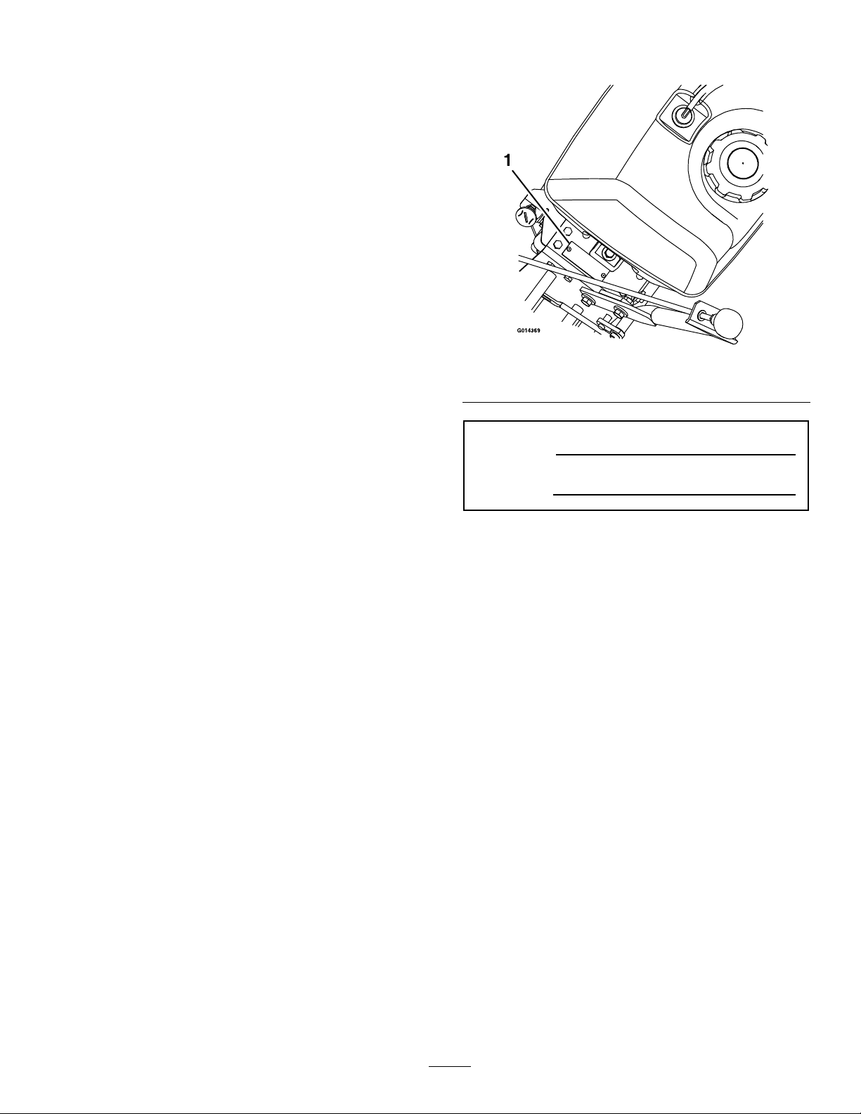
Figure1
1.Modelandserialnumberlocation
ModelNo.
SerialNo.
AllExmarkequipmentdealersanddistributorsare
keptinformedofthelatestmethodsofservicing
andareequippedtoprovidepromptandefcient
serviceintheeldorattheirservicestations.They
carryamplestockofservicepartsorcansecurethem
promptlyforyoufromthefactory.
AllExmarkpartsarethoroughlytestedandinspected
beforeleavingthefactory,however,attentionis
requiredonyourpartifyouaretoobtainthefullest
measureofsatisfactionandperformance.
Wheneveryouneedservice,genuineExmarkparts,
oradditionalinformation,contactanAuthorized
ServiceDealerorExmarkCustomerServiceandhave
themodelandserialnumbersofyourproductready .
Figure1identiesthelocationofthemodelandserial
numbersontheproduct.Writethenumbersinthe
spaceprovided.
3
Page 4

Contents
Introduction...........................................................3
Safety.....................................................................5
SafetyAlertSymbol.........................................5
SafeOperatingPractices..................................5
SafetyandInstructionalDecals.....................10
Specications.......................................................13
ModelNumbers............................................13
Systems.........................................................13
Dimensions...................................................14
TorqueRequirements....................................14
ProductOverview................................................15
Operation.............................................................15
Controls........................................................15
Pre-Start........................................................17
OperatingInstructions..................................17
Transporting.................................................19
Maintenance.........................................................20
RecommendedMaintenanceSchedule(s)...........20
PeriodicMaintenance.......................................21
CheckEngineOilLevel.................................21
CheckMowerBlades.....................................21
CheckSafetyInterlockSystem.......................22
CheckforLooseHardware............................22
ServiceAirCleaner........................................23
ChangeEngineOil........................................23
CheckHydraulicOilLevel.............................23
CheckTirePressures.....................................23
CheckConditionOfBelts..............................23
LubricateGreaseFittings...............................24
CheckSparkPlugs.........................................24
ChangeHydraulicSystemFilter.....................24
ReplaceEmissionsAirIntakeFilter................26
WheelHub-SlottedNutTorque
Specication..............................................26
ThreadLockingAdhesives.............................27
MobilHTSGrease(OrFood-Grade
Anti-seize).................................................27
Copper-BasedAnti-seize..............................27
DielectricGrease...........................................27
Adjustments.....................................................28
AdjustingtheCuttingHeight.........................28
AdjustingtheAxlePosition............................29
AdjustingtheNumberofSpacersbelow
CasterSupportHub...................................30
AdjustingtheCuttingHeightwithBlade
Spacers......................................................30
PTOEngagementLinkage
Adjustment...............................................31
PTOSafetySwitchAdjustment......................31
EnginetoMowerDeckBelt
Adjustment...............................................31
BladeBrakeAdjustment................................32
BeltGuideAdjustment..................................33
PumpDriveBeltTension...............................33
HydroDriveLinkageAdjustment..................33
TrackingAdjustment.....................................36
HydroPumpSpringTensionSetting..............36
ParkBrakeAdjustment..................................36
Cleaning...........................................................37
CleanEngineAirCoolingSystem...................37
RemoveEngineShroudsandCleanCooling
Fins...........................................................37
CleanGrassBuild-UpUnderDeck................37
WasteDisposal..............................................37
Troubleshooting...................................................38
Schematics...........................................................40
4
Page 5

Safety
Safety
SafetyAlertSymbol
ThislawnmowermeetsorexceedstheB71.4
specicationsoftheAmericanNationalStandards
Instituteineffectatthetimeofproduction.
Exmarkdesignedandtestedthislawnmowertooffer
reasonablysafeservice;however,failuretocomply
withthefollowinginstructionsmayresultinpersonal
injury.
ThisSafetyAlertSymbol(Figure2)isusedbothin
thismanualandonthemachinetoidentifyimportant
safetymessageswhichmustbefollowedtoavoid
accidents.
Thissymbolmeans:ATTENTION!BECOME
ALERT!YOURSAFETYISINVOLVED!
Figure2
1.Safetyalertsymbol
notreadEnglishitistheowner’sresponsibilityto
explainthismaterialtothem.
•Becomefamiliarwiththesafeoperationofthe
equipment,operatorcontrols,andsafetysigns.
•Alloperatorsandmechanicsshouldbetrained.
Theownerisresponsiblefortrainingtheusers.
•Neverletchildrenoruntrainedpeopleoperate
orservicetheequipment.Localregulationsmay
restricttheageoftheoperator.
•Onlyadultsandmatureteenagersshouldoperate
amower,andevenmatureteenagersshouldhave
adultsupervision.Besureateenager:
1.hasreadandunderstandstheOperator’s
Manualandrecognizestherisksinvolved;
2.issufcientlymaturetousecaution;and
3.isofsufcientsizeandweighttooperate
thecontrolscomfortablyandtomanagethe
mowerwithouttakingrisks.
•Theowner/usercanpreventandisresponsible
foraccidentsorinjuriesoccurringtohimselfor
herself,otherpeopleorproperty.
Thesafetyalertsymbolappearsaboveinformation
whichalertsyoutounsafeactionsorsituations
andwillbefollowedbythewordDANGER,
WARNING,orCAUTION.
DANGER:Whitelettering/Redbackground.
Indicatesanimminentlyhazardoussituationwhich,if
notavoided,Willresultindeathorseriousinjury.
WARNING:Blacklettering/Orangebackground.
Indicatesapotentiallyhazardoussituationwhich,if
notavoided,Couldresultindeathorseriousinjury.
CAUTION:Blacklettering/Yellowbackground.
Indicatesapotentiallyhazardoussituationwhich,if
notavoided,Mayresultinminorormoderateinjury.
Thismanualusestwootherwordstohighlight
information.Importantcallsattentiontospecial
mechanicalinformationandNoteemphasizes
generalinformationworthyofspecialattention.
SafeOperatingPractices
Training
•ReadtheOperator’sManualandothertraining
material.Iftheoperator(s)ormechanic(s)can
Preparation
•Evaluatetheterraintodeterminewhataccessories
andattachmentsareneededtoproperlyand
safelyperformthejob.Onlyuseaccessoriesand
attachmentsapprovedbyExmark.
•Wearappropriateclothingincludingsafetyglasses,
substantialfootwear,longtrousers,andhearing
protection.DoNotoperatewhenbarefootor
whenwearingopensandals.Longhair,loose
clothingorjewelrymaygettangledinmoving
parts.
CAUTION
Thismachineproducessoundlevelsinexcess
of85dBAattheoperator’searandcancause
hearinglossthroughextendedperiodsof
exposure.
Wearhearingprotectionwhenoperatingthis
machine.
•Inspecttheareawheretheequipmentistobe
usedandremoveallrocks,toys,sticks,wires,
bones,andotherforeignobjectswhichcanbe
thrownbythemachineandmaycausepersonal
injurytotheoperatororbystanders.
5
Page 6

Safety
DANGER
Incertainconditionsgasolineisextremely
ammableandvaporsareexplosive.
Areorexplosionfromgasolinecanburn
you,others,andcausepropertydamage.
•Fillthefueltankoutdoorsonlevelground,
inanopenarea,whentheengineiscold.
Wipeupanygasolinethatspills.
•Neverrellthefueltankordrainthe
machineindoorsorinsideanenclosed
trailer.
•DoNotllthefueltankcompletelyfull.
Fillthefueltanktothebottomoftheller
neck.Theemptyspaceinthetankallows
gasolinetoexpand.Overllingmayresult
infuelleakageordamagetotheengine
oremissionsystem.
•Neversmokewhenhandlinggasoline,and
stayawayfromanopenameorwhere
gasolinefumesmaybeignitedbyspark.
•Storegasolineinanapprovedcontainer
andkeepitoutofthereachofchildren.
•Addfuelbeforestartingtheengine.Never
removethecapofthefueltankoradd
fuelwhenengineisrunningorwhenthe
engineishot.
DANGER
Incertainconditionsduringfueling,static
electricitycanbereleasedcausingaspark
whichcanignitegasolinevapors.Areor
explosionfromgasolinecanburnyouand
othersandcausepropertydamage.
•Alwaysplacegasolinecontainersonthe
groundawayfromyourvehiclebefore
lling.
•DoNotllgasolinecontainersinsidea
vehicleoronatruckortrailerbedbecause
interiorcarpetsorplastictruckbedliners
mayinsulatethecontainerandslowthe
lossofanystaticcharge.
•Whenpractical,removegas-powered
equipmentfromthetruckortrailerand
refueltheequipmentwithitswheelson
theground.
•Ifthisisnotpossible,thenrefuelsuch
equipmentonatruckortrailerfroma
portablecontainer,ratherthanfroma
gasolinedispensernozzle.
•Ifagasolinedispensernozzlemustbe
used,keepthenozzleincontactwiththe
rimofthefueltankorcontaineropening
atalltimesuntilfuelingiscomplete.
•Iffuelisspilled,DoNotattempttostart
theengine.Moveawayfromtheareaof
thespillandavoidcreatinganysourceof
ignitionuntilfuelvaporshavedissipated.
•DoNotoperatewithoutentireexhaust
systeminplaceandinproperworking
condition.
WARNING
Gasolineisharmfulorfatalifswallowed.
Long-termexposuretovaporshascaused
cancerinlaboratoryanimals.Failuretouse
cautionmaycauseseriousinjuryorillness.
•Avoidprolongedbreathingofvapors.
•Keepfaceawayfromnozzleandgas
tank/containeropening.
•Keepawayfromeyesandskin.
•Neversiphonbymouth.
•Checkthattheoperator’spresencecontrols,
safetyswitches,andshieldsareattachedand
functioningproperly.DoNotoperateunlessthey
arefunctioningproperly.
6
Page 7

Safety
Operation
WARNING
Operatingengineparts,especiallythemufer,
becomeextremelyhot.Severeburnscanoccur
oncontactanddebris,suchasleaves,grass,
brush,etc.cancatchre.
•Allowengineparts,especiallythemufer,to
coolbeforetouching.
•Removeaccumulateddebrisfrommufer
andenginearea.
•Installandmaintaininworkingordera
sparkarresterbeforeusingequipment
onforest-covered,grass-covered,or
brush-coveredunimprovedland.
WARNING
Engineexhaustcontainscarbonmonoxide,
whichisanodorlessdeadlypoisonthatcankill
you.
DoNotrunengineindoorsorinasmallconned
areawheredangerouscarbonmonoxidefumes
cancollect.
•Operateonlyindaylightorgoodarticiallight,
keepingawayfromholesandhiddenhazards.
•Besurealldrivesareinneutralandparkingbrake
isengagedbeforestartingengine.
•Neverraisedeckwithbladesrunning.
•Neveroperatethemowerwithdamagedguards,
shields,orcovers.Alwayshavesafetyshields,
guards,switchesandotherdevicesinplaceandin
properworkingcondition.
•Nevermowwiththedischargedeectorraised,
removedoralteredunlessthereisagrass
collectionsystemormulchkitinplaceand
workingproperly.
•DoNotchangetheenginegovernorsettingor
overspeedtheengine.
•Parkmachineonlevelground.Stopengine,wait
forallmovingpartstostop,removekeyand
engageparkingbrake:
–Beforechecking,cleaningorworkingonthe
mower.
–Afterstrikingaforeignobjectorabnormal
vibrationoccurs(inspectthemowerfor
damageandmakerepairsbeforerestarting
andoperatingthemower).
–Beforeclearingblockages.
–Wheneveryouleavethemower.
•Stopengine,waitforallmovingpartstostop,and
engageparkingbrake:
–Beforerefueling.
–Beforedumpingthegrasscatcher.
–Beforemakingheightadjustments.
WARNING
Hands,feet,hair,clothing,oraccessoriescan
becomeentangledinrotatingparts.Contact
withtherotatingpartscancausetraumatic
amputationorseverelacerations.
•DoNotoperatethemachinewithout
guards,shields,andsafetydevicesin
placeandworkingproperly.
•Keephands,feet,hair,jewelry,orclothing
awayfromrotatingparts.
•DONOToperatethemowerwhenpeople,
especiallychildren,orpetsareinthearea.
•Bealert,slowdownandusecautionwhenmaking
turns.Lookbehindandtothesidebefore
changingdirections.
•Stoptheblades,slowdown,andusecautionwhen
crossingsurfacesotherthangrassandwhen
transportingthemowertoandfromtheareato
bemowed.
•Beawareofthemowerdischargepathanddirect
dischargeawayfromothers.
•DoNotoperatethemowerundertheinuence
ofalcoholordrugs.
•Useextremecarewhenloadingorunloadingthe
machineintoatrailerortruck.
•Usecarewhenapproachingblindcorners,shrubs,
trees,orotherobjectsthatmayobscurevision.
SlopeOperation
UseExtremecautionwhenmowingand/orturning
onslopesaslossoftractionand/ortip-overcould
occur.Theoperatorisresponsibleforsafeoperation
onslopes.
7
Page 8

Safety
DANGER
Operatingonwetgrassorsteepslopescan
causeslidingandlossofcontrol.Lossofcontrol
and/orlossofoperator’sfootingcouldresultina
fallwithanarmorleggettingunderthemower
orenginedeckwhichmayresultinserious
injury,deathordrowning .
•Mowacrossslopes,neverupanddown.
•DoNotmowslopeswhengrassiswet.
•DoNotmowneardrop-offsornearwater.
•DoNotmowslopesgreaterthan20degrees.
•Reducespeedanduseextremecautionon
slopes.
•Avoidsuddenturnsorrapidspeedchanges.
•Seeinsidethebackcovertodeterminethe
approximateslopeangleoftheareatobemowed.
•Removeormarkobstaclessuchasrocks,tree
limbs,etc.fromthemowingarea.Tallgrasscan
hideobstacles.
•Watchforditches,holes,rocks,dipsandrisesthat
changetheoperatingangle,asroughterraincould
overturnthemachine.
•Avoidsuddenstartswhenmowinguphillbecause
themowermaytipbackwards.
•Beawarethatoperatingonwetgrass,acrosssteep
slopesordownhillmaycausethemowertolose
traction.Lossoftractiontothedrivewheelsmay
resultinslidingandalossofbrakingandsteering.
•Keepengineandengineareafreefrom
accumulationofgrass,leaves,excessivegrease
oroil,andotherdebriswhichcanaccumulate
intheseareas.Thesematerialscanbecome
combustibleandmayresultinare.
•Letenginecoolbeforestoringanddonotstore
nearameoranyenclosedareawhereopenpilot
lightsorheatappliancesarepresent.
•Shutofffuelwhilestoringortransporting.Do
Notstorefuelnearamesordrainindoors.
•Parkmachineonlevelground.Neverallow
untrainedpersonneltoservicemachine.
•Usejackstandstosupportcomponentswhen
required.
•Carefullyreleasepressurefromcomponentswith
storedenergy.
•Usecarewhencheckingblades.Wraptheblade(s)
orweargloves,andusecautionwhenservicing
them.Onlyreplacedamagedblades.Never
straightenorweldthem.
•Keephandsandfeetawayfrommovingparts.
Ifpossible,donotmakeadjustmentswiththe
enginerunning.
•Keepallguards,shieldsandallsafetydevicesin
placeandinsafeworkingcondition.
•Checkallboltsfrequentlytomaintainproper
tightness.
•Frequentlycheckforwornordeteriorating
componentsthatcouldcreateahazard.
•Alwaysavoidsuddenstartingorstoppingona
slope.Iftireslosetraction,disengagetheblades
andproceedslowlyofftheslope.
•Followthemanufacturer’srecommendationsfor
wheelweightsorcounterweightstoimprove
stability.
•Useextremecarewithgrasscatchersor
attachments.Thesecanchangethestabilityofthe
machineandcauselossofcontrol.
MaintenanceandStorage
•Disengagedrives,lowerimplement,setparking
brake,stopengineandremovekeyordisconnect
sparkplugwire.Waitforallmovementtostop
beforeadjusting,cleaningorrepairing.
WARNING
Removingstandardoriginalequipmentparts,
orusingnon-Exmarkreplacementpartsand
accessoriesmayalterthewarranty,traction,and
safetyofthemachine.Failuretouseoriginal
Exmarkpartscouldcauseseriousinjuryor
death.
Replaceallpartsincluding,butnotlimitedto,
tires,belts,andbladeswithoriginalExmark
parts.
8
Page 9

WARNING
Hydraulicuidescapingunderpressure
canpenetrateskinandcauseinjury.Fluid
accidentallyinjectedintotheskinmustbe
surgicallyremovedwithinafewhoursbyadoctor
familiarwiththisformofinjuryorgangrenemay
result.
•Ifequipped,makesureallhydraulicuid
hosesandlinesareingoodconditionandall
hydraulicconnectionsandttingsaretight
beforeapplyingpressuretohydraulicsystem.
•Keepbodyandhandsawayfrompinhole
leaksornozzlesthatejecthighpressure
hydraulicuid.
•Usecardboardorpaper,notyourhands,to
ndhydraulicleaks.
•Safelyrelieveallpressureinthehydraulic
systembyplacingthemotioncontrollevers
inneutralandshuttingofftheenginebefore
performinganyworkonthehydraulicsystem.
Safety
9
Page 10
Safety
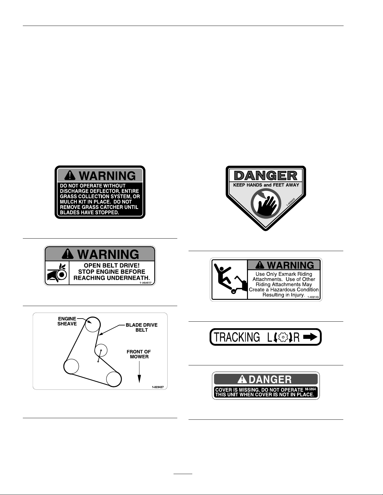
SafetyandInstructionalDecals
•Keepallsafetysignslegible.Removeallgrease,
dirtanddebrisfromsafetysignsandinstructional
labels.
•Replaceallworn,damaged,ormissingsafety
signs.
•Whenreplacementcomponentsareinstalled,be
surethatcurrentsafetysignsareafxedtothe
replacedcomponents.
•Ifanattachmentoraccessoryhasbeeninstalled,
makesurecurrentsafetysignsarevisible.
1-303508
•Newsafetysignsmaybeobtainedfrom
yourauthorizedExmarkequipmentdealeror
distributororfromExmarkMfg.Co.Inc.
•Safetysignsmaybeafxedbypeelingoffthe
backingtoexposetheadhesivesurface.Apply
onlytoaclean,drysurface.Smoothtoremove
anyairbubbles.
•Familiarizeyourselfwiththefollowingsafetysigns
andinstructionlabels.Theyarecriticaltothesafe
operationofyourExmarkcommercialmower.
1-403005
1-303517
1-323427
36inchDeckUnitsOnly
1-403143
1-413214
98-5954
10
Page 11

Safety
103-1798
103-2076
103-2103
103-2196
103–2242
11
Page 12
Safety
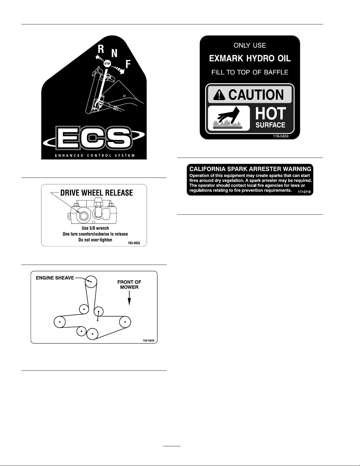
116-0404
103–2243
103-4935
103-5626
48inchDeckUnitsOnly
117–2718
12
Page 13

Specications
ModelNumbers
SerialNos:920,000andHigher
VH16KA362;VH16KA483;VH16KA362CA;VH16KA483CA
Specications
Systems
Engine
•EngineSpecications:SeeyourEngineOwner’s
Manual
•EngineOilType:Exmark4–CyclePremium
EngineOil
•RPM:FullSpeed:3600(NoLoad)
Idle:1550RPM
FuelSystem
•Capacity:5.0gal.(18.9L)
•TypeofFuel:Regularunleadedgasoline,87
octaneorhigher;containingnomorethan10%
methanolorethanol.
•FuelFilter:ReplaceableIn-line
•FuelShut-OffValve:1/4turnincrements
SafetyInterlockSystem:
Transmission
•TwoHydroGearvariabledisplacementpiston
pumpsindependentlycoupledtotwohigh
efciencyParkerwheeldrivemotors.
•HydraulicOil:UseExmarkPremiumHydroOil.
•HydraulicOilCapacity:2.4qt.(2.2L)
•HydraulicFilterisreplaceablecartridgetype.
P/N109–4180:25microns,10psibypass
(Summeruseabove32°F(0°C))
P/N1–523541:40microns,18psibypass(Winter
usebelow32°F(0°C))
•Speeds:
–0-6.2mph(10.0km/hr)forward.
–0-2.2mph(3.5km/hr)reverse.
WheelDriveSystem
DrivewheelsaredirectcoupledtoParkerwheeldrive
motorswith1inch(25.4mm)taperedshaft.
•OperatormusthaveOPC(OperatorPresence
Control)leversheldincontactwithhandle
grips,speedcontrolleverinneutral,andPTO
disengagedtostartengine.ReleaseofOPClevers
willcausetheenginetostopifspeedcontrollever
isnotinneutraland/orPTOisengaged.
•Parkbrakemustbedisengagedtomovespeed
controloutofneutralorenginewillkill.
Steering/BrakeControls
Fingertipdrivecontrolleversprovideindependent
speedcontrol,brakingandneutraltoeachdrive
wheelformovingforwardorreverse,stoppingand
powerturning.
Tires&Wheels
DriveFrontCaster
Pneumatic
(Air-Filled)
Quantity
Tread
Size16x6.50–89x3.50-4
PlyRating
Pressure
13
22
TurfMasterSmooth
4
14psi
(97kPa)
SemiPneumatic
Page 14

Specications
CuttingDeck
•CuttingWidth:
–36inchDeck:35.38inches(89.9cm)
–48inchDeck:47.25inches(120.0cm)
•Discharge:Side
•BladeSize:
–36inchDeck:18.00inches(45.7cm)—
Quantity:2
–48inchDeck:16.25inches(41.3cm)—
Quantity:3
•DeckDrive:Manualengagementofbeltwith
over-centerlock.Bladebelttensionisadjustable
viaturnbuckle.
•BladeBrake:WhenthePTOengagementcontrol
ismovedtothedisengagedpositionafriction
brakepadstopstherotationoftheblades.
•DeckMounting:Bolteddirectlytoenginedeck.
•DeckDepth:
–36inchDeck:5.0inches(12.7cm)
–48inchDeck:5.0inches(12.7cm)
•CuttingHeightAdjustment:
Adjustsfrom1inch(2.5cm)to41/4inches(10.8
cm)in1/4inch(6.4mm)incrementsbyvarious
adjustmentsofcasterspacers,bladespacers,and
axleheight.
Dimensions
TreadWidth:(OutsidetoOutsideof
Tires,Widthwise)
36inchDeck48inchDeck
35.6inches
(90.4cm)
40.4inches
(102.6cm)
CurbWeight:
36inchDeck48inchDeck
573lb(260kg)633lb(287kg)
TorqueRequirements
BoltLocation
Blade/CutterHousing
SpindleBolt
CasterBracketMounts
MowerDeck/Engine
DeckMount
EngineMountingBolts
WheelLugNuts
WheelHubSlottedNut
(StyleA)
WheelHubSlottedNut
(StyleB)
WheelMotorMounting
Bolts
Torque
75-80ft-lb(102-109N-m)
30-35ft-lb(41-48N-m)
30-35ft-lb(41-48N-m)
17-23ft-lb(23-31N-m)
90-95ft-lb(122-129N-m)
140-155ft-lb
(190-210N-m)
minimum100ft-lb
(136N-m)
30-35ft-lb(41-48N-m)
OverallWidth:
36inchDeck48inchDeck
DeectorUp36.4inches
(92.5cm)
DeectorDown47.0inches
(119.4cm)
48.1inches
(122.2cm)
57.9inches
(147.1cm)
OverallLength:
36inchDeck48inchDeck
77.3inches(196.3cm)72.3inches(183.6cm)
OverallHeight:
36inchDeck48inchDeck
43.2inches(109.7cm)43.2inches(109.7cm)
14
Page 15
Operation
ProductOverview
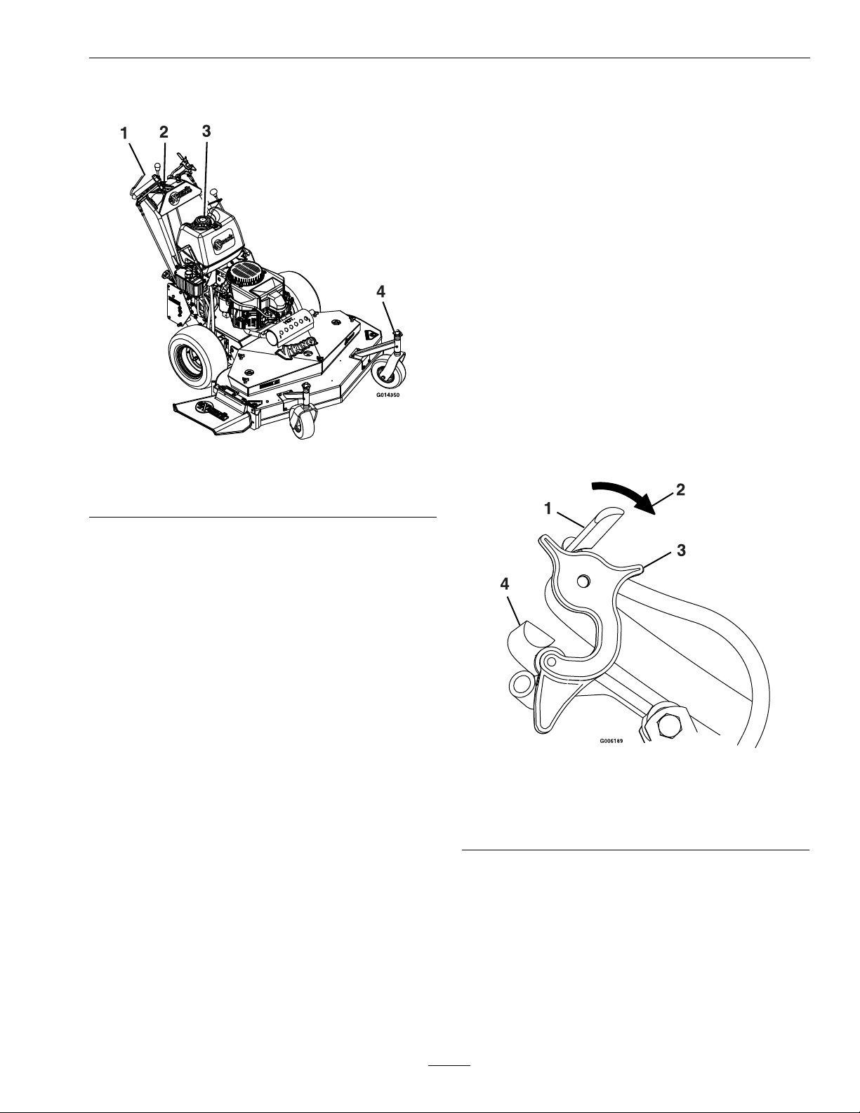
Figure3
1.ECSHandles3.FuelCap
2.Controls4.BladeSpacers
Operation
Note:Determinetheleftandrightsidesofthe
machinefromthenormaloperatingposition.
Controls
OperatorPresenceControl(OPC)
Levers
Locatedontheupperhandleassemblydirectlyabove
thehandlegrips.
Whentheseleversaredepressed,theOPCsystem
sensesthattheoperatorisinthenormaloperator’s
position.Whentheleversarereleased,theOPC
systemsensesthattheoperatorhasmovedfromthe
normaloperatingpositionandwillkilltheengineif
eitherthespeedcontrolleverisnotintheneutral
positionorthePTOisengaged(see
Figure4).
Figure4
1.OPCLever
2.Rotateneutrallocklatch
downwardforneutral
lockposition
3.NeutralLockLatch
4.DriveLeverinneutral
position
DriveLevers
Locatedoneachsideoftheupperhandleassembly
aheadofandbelowthehandlegrips.
Theseleversindividuallycontrolthespeedand
directionofeachdrivewheel.Whenthespeedcontrol
leverismovedoutoftheneutralpositionandthe
neutrallocklatchesaremovedintothedriveposition,
15
Page 16

Operation
asshowninFigure4,andthedriveleversarereleased,
thedrivewheelsareengagedintheforwarddirection.
Squeezingthelefthandand/orrighthandlever
causesthelefthandand/orrighthanddrivewheel
respectivelytoslowdown,stop,orreverse,depending
onhowfareachdriveleveris“squeezed”.Squeezing
thedriveleversbeyondtheneutralpositioncauses
thedrivewheelstoengageinthereversedirection
regardlessofthepositionoftheneutrallocklatches
andthespeedcontrollever.
NeutralLockLatch
Locatedattheendofthehandles.
Thepurposeoftheselatchesistoallowtheoperator
tolockthedriveleversina"neutral"positionwhere
neitherofthedrivewheelsareengagedineithera
forwardorreversedirection(see
Figure4).
ParkBrakeLever
Locatedontherightsideoftheunitabovethe
hydraulictank.
Thebrakeleverengagestheparkbrakeonthedrive
wheels.
Pulltheleverupandrearwardtoengagethebrake.
Pushtheleverforwardanddowntodisengagethe
brake.
Whenparkingonasteepslope,thewheelsmustbe
chockedorblockedinadditiontothebrakebeing
engaged.Theunitmustbetieddownandbrake
engagedwhentransporting.
speedandmovingittotherearwilldecreaseengine
speed.Movingthethrottleforwardintothedetent
isfullposition.
SpeedControlLever
Locatedinmiddleofcontrolconsole.
Thespeedcontrollevercontrolsthemaximum
forwardspeedandisinnitelyvariablefromneutral
0–6.2mph(10.0km/hr).
Parkbrakemustbedisengagedtomovespeedcontrol
outofneutralorenginewillkill.
“Off-Run”Switch
Locatedonthecontrolconsole.
Turnthekeytothe“Run”positiontoallowthe
enginetobestarted.Turnthekeytothe“Off”
positiontoshutengineoff.
FuelShut-OffValve
Locatedinthefuellinemidwaybetweenthetank
andengine.
Thefuelshut-offvalveisusedtoshutoffthe
owoffuelwhenparkinginsideabuilding,during
transportationtoandfromthejobsites,andwhen
themachinewillnotbeusedforafewdays.
Rotatevalve1/4turnclockwisetoshutfueloff.
Rotatevalve1/4turncounterclockwisetoturnfuel
on.
Parkbrakemustbedisengagedtomovespeedcontrol
outofneutralorenginewillkill.
ChokeControl
Locatedonthefrontleftcornerofthefueltank
support.
Chokeisusedtoaidinstartingacoldengine.The
chokecontrolispulledouttobeinthe“ON”position
andpushedintobeinthe“OFF”position.DoNot
runawarmenginewithchokeinthe“ON”position.
ThrottleControl
Locatedontheonthecontrolconsolerightside.
Thethrottleisusedtocontrolenginespeed.Moving
thethrottlecontrolforwardwillincreaseengine
DriveWheelReleaseValves
Locatedonthetoprearcornerofthehydrostatic
pumps.
Drivewheelreleasevalvesareusedtoreleasethe
hydro-staticdrivesystemtoallowthemachinetobe
movedbyhandwithouttheenginerunning.
Witha5/8wrench,turnbothvalvesoneturn
counterclockwisetoreleasethedrivesystem.
Turnclockwisetoresetthedrivesystem.DoNot
overtighten.
TrackingAdjustmentKnob
Locatedontheright-handsideoftherearofthefuel
tanksupport.
16
Page 17

Operation
Theknobcanbeadjustedsothatmachinewill
“track”straightaheadwiththedriveleversreleased.
PTOEngagementControl
Locatedonleftsideofcontrolconsole.
Toengagetheblades,theknobmustbepulled
towardtheoperatoruntiltheturnbuckle(attached
tothebladeengagementidler)locksover-center.T o
disengagetheblades,pushtheknobdownuntilthe
assistarmcontactsthepinonthedeck.
ParkbrakemustbedisengagedbeforePTOis
engagedorenginewillkill.
ColdStartKit
Locatedontherighthandsideofenginedeck,below
andslightlyaheadofthehydrocontrolshield.
Thecoldstartkitisusedtoeasethestartingofthe
unitincoldweatherorwhentheunithasnotbeen
operatedforaperiodoftime.Thecoldstartkit
movestheidlerpulleyawayfromthepumpbelt,
releasingthetensiononthebeltwhichallowsthe
enginetoturnoverwithlessresistance(seeStarting
theEnginesectioninOperation).
Pre-Start
Fillfueltankonlevelground.Forbestresultsuse
onlyclean,freshregulargradeunleadedgasolinewith
anoctaneratingof87orhigher.
Important:Neverusemethanol,gasoline
containingmethanol,gasoholcontainingmore
than10%ethanol,premiumgasoline,orwhite
gasbecausethefuelsystemcouldbedamaged.
DoNotaddoiltogasoline.
DoNotoverllfueltank.Fillthefueltanktothe
bottomofthellerneck.Theemptyspaceinthe
tankallowsgasolinetoexpand.Overllingmayresult
infuelleakageordamagetotheengineoremission
system.
Makesureyouunderstandthecontrols,their
locations,theirfunctions,andtheirsafety
requirements.
OperatingInstructions
OpentheFuelShut-OffValve
Rotatethevalve1/4turncounterclockwisetoturn
fuelon.
StartingtheEngine
Note:OperatormusthavePTOdisengagedand
speedcontrolleverinneutralpositionwhenstarting
theengine.
Lockdriveleversinneutralandengageparkbrake
Note:Acoldweatherstartingkithasbeenaddedfor
easeofstartingineithercoldweatherorwhenthe
unithasnotbeenrunforaperiodoftime.
•Tousecoldstartkit:
1.Pullsplitringstraightoutthesideoftheunit,
andhooktheringoverthelowerfronthydro
controlshieldbolt.
2.Startengine.Refertothefollowingguidelines
forfurtherstartingsuggestions.
•Toengagepumpdrive(disengagecoldstartkit):
1.Pullchainstraightoutfromthesideofthe
unituntilthesplitringcanberemovedfrom
thebolt.
2.Slowlyreleasetensiononchain.
1.Pulloutthechokecontrol.Placethethrottle
controlmidwaybetweenthe“Slow”and“Fast”
positions.Turnthekeyswitchtothe“Run”
position.
2.Pullrecoilropetostartengine.Afterengine
warmsup,graduallypushinthechokecontrol.
DoNotrunwarmenginewiththechokeinthe
“ON”position.
Note:Kawasakienginesgenerallyneedtobe
“choked”evenwhenwarm.
EngagingthePTO
DANGER
Therotatingbladesunderthemowerdeckare
dangerous.Bladecontactcancauseserious
injuryorkillyou.
RefertotheMaintenancesectionandperformallthe
necessaryinspectionandmaintenancesteps.
DoNotputhandsorfeetunderthemoweror
mowerdeckwhenthebladesareengaged.
17
Page 18

Operation
DANGER
Anuncovereddischargeopeningwillallow
objectstobethrowninanoperator’sor
bystander’sdirection.Also,contactwiththe
bladecouldoccur.Thrownobjectsorblade
contactcancauseseriousinjuryordeath.
Neveroperatethemowerwiththedischarge
deectorraised,removed,oralteredunlessthere
isagrasscollectionsystemormulchkitinplace
andworkingproperly.
ThePTOswitchengagesthecuttingblades.Besure
thatallpersonsareclearofmowerdeckanddischarge
areabeforeengagingthePTO.
1.Setthrottleto“MIDW AY”position.
2.PullthePTOengagementknobuptoengage
blades.
3.Placethethrottleinthe“FAST”positiontobegin
mowing.
Note:ParkbrakemustbedisengagedbeforePTOis
engagedorenginewillkill.
DisengagingthePTO
1.Setthrottleto“MIDW AY”position.
2.PushdownonthePTOengagementknobto
disengagetheblades.
StoppingtheEngine
transporting,orwhentheunitisparkedinside
abuilding.
DrivingtheMachine
DriveLever/NeutralLockLatchOperation
Tolockthedriveleversin“neutrallock”,squeezethe
driveleverstothe“neutral”position(DoNotsqueeze
thedriveleversallthewaybackasthiswillcausethe
drivewheelstogointofullreversedirection).See
Figure5position1.Placethumbsontheinnerlobe
oftheneutrallocklatchesandrotatethemunder
thedriveleversintothe“neutrallock”position.See
Figure5position2.Releasethedrivelevers.
CAUTION
Iftheneutrallocklatchesarenotcompletely
engagedthedriveleverscouldunexpectedlyslip
intotheforwarddriveposition.Ifthedrivelevers
slipintothedrivepositiontheunitcouldlurch
forwardandcauseinjuryorpropertydamage.
Besurethedriveleversarepasttherollerand
securelyseatedatthebottomoftheneutrallock
latches.
Toplacethedriveleversinthe“forward”position,
slightlysqueezethedriveleverswhileplacingthumbs
ontheouterthumblobeoftheneutrallocklatches
(ortheindexngeronthefrontlobe)androtatethem
fromunderthedrivelevers.Slowlyandcarefully
releasethedrivelevers.See
Figure5position3.
1.Bringtheunittoafullstop.
2.Lockdriveleversinneutral.
3.DisengagethePTO.
4.Movespeedcontrollevertoneutral.
5.Engagetheparkingbrake.
6.Placethethrottlemidwaybetweenthe“SLOW”
and“FAST”positions.
7.Allowtheenginetorunforaminimumof15
seconds,thenturntheignitionswitchtothe
“OFF”positiontostoptheengine.
8.Removethekeytopreventchildrenorother
unauthorizedpersonsfromstartingengine.
9.Closethefuelshut-offvalvewhenthemachine
willnotbeinuseforafewdays,when
Toplacethedriveleversinthe“reverse”position,
squeezethedriveleverspasttheneutralposition.See
Figure5position4.
18
Page 19

1.DriveLeverinneutral
position
2.DriveLeverlockedin
neutralposition
DrivingForward
Figure5
3.DriveLeverinforward
position
4.DriveLeverinreverse
position
Operation
DrivinginReverse
Tomoverearwardinastraightline,squeezedrive
leversintothereverseposition.
Toturnleftorright,squeezetherighthanddrivelever
toturnleftandthelefthanddrivelevertoturnright.
Tomakea“zeroturn”,squeezeeitherthelefthand
ortherighthanddriveleverbackintothereverse
positionwhiletheoppositedriveleverisinaforward
positionatanequalbutoppositespeed.
Note:Forsmoothoperationofthismachine,avoid
quick,jerkymovementsofthedrivelevers.Movethe
driveleverssmoothlyanddeliberately.
Tostop,squeezedriveleversbacktothe“neutral”
position.Movetheneutrallocklatchesintothe
“neutrallock”positionandreleasedrivelevers.Move
thespeedcontrollevertotheneutralposition.
1.Releasetheparkingbrake.
2.Withdriveleverslockedin“neutral”,shiftspeed
controllevertodesiredforwardspeed.
3.Slowlysqueezeandholdbothdriveleversin
theneutralpositionandrotatebothneutrallock
latchesfromtheneutrallockpositiontothe
forwardposition.
Note:DoNotsqueezebothdriveleversallthe
wayback.Thiswillcausethedrivewheelsto
engageinthereversedirection.
4.Tomoveforwardinastraightline,smoothly
releasebothdriveleverstoengagedrivewheels.
Toturnleftorright,squeezetherighthanddrive
levertoturnrightandthelefthanddrivelever
toturnleft.
Tomakea“zeroturn”,squeezeeithertheleft
handortherighthanddriveleverbackintothe
reversepositionwhiletheoppositedriveleverisin
aforwardpositionatanequalbutoppositespeed.
Note:Forsmoothoperationofthismachine,
avoidquick,jerkymovementsofthedrivelevers.
Movethedriveleverssmoothlyanddeliberately .
Tostop,squeezedriveleversbacktothe“neutral”
position.Movetheneutrallocklatchesintothe
“neutrallock”positionandreleasedrivelevers.
Movethespeedcontrollevertotheneutral
position.
Transporting
TransportingaUnit
WARNING
Loadingthemowerontoatrailerwithoutstrong
enoughorproperlysupportedrampscouldbe
dangerous.Therampscouldcollapsecausing
theunittofall,whichcouldcauseinjury.
•Useproperrampsthataresecuredtothe
truckortrailer.
•Keepfeetandlegsoutfromundertheunit
whenloadingandunloading.
•Ifnecessary,useassistancewhenloading.
Besurethefuelshut-offvalveisclosed.
Useaheavydutytrailertotransportthemachine.
Engageneutrallocklatchesandparkbrake,then
blockwheels.
Securelyfastenthemachinetothetrailerwithstraps,
chains,cables,orropes.
DoNotrelysolelyontheparkingbraketoholdthe
machineonthetrailer.
Besurethatthetrailerhasallnecessarylightingand
markingasrequiredbylawanduseasafetychain.
19
Page 20

Maintenance
Maintenance
Note:Determinetheleftandrightsidesofthemachinefromthenormaloperatingposition.
WARNING
Whilemaintenanceoradjustmentsarebeing
made,someonecouldstarttheengine.
Accidentalstartingoftheenginecouldseriously
injureyouorotherbystanders.
Removethekeyfromtheignitionswitch,engage
parkingbrake,andpullthewire(s)offthespark
plug(s)beforeyoudoanymaintenance.Also
pushthewire(s)asidesoitdoesnotaccidentally
contactthesparkplug(s).
RecommendedMaintenanceSchedule(s)
MaintenanceService
Interval
Aftertherst5hours
Aftertherst100hours
Aftertherst250hours
Beforeeachuseordaily
MaintenanceProcedure
•Changetheengineoil.
•Checkwheelhub-slottedtorquespecication.
•Changethehydrauliclter.
•Checktheengineoillevel.
•Checkthemowerblades.
•Checkthesafetyinterlocksystem.
•Checkforloosehardware.
•Greasethecasterwheelbearings.
•Greasecasterpivots.
•Cleanengineaircoolingsystem(SeeEngineOwner’ sManual)
•Cleanthegrassbuild-upfromunderthedeck.
WARNING
Theenginecanbecomeveryhot.Touchingahot
enginecancausesevereburns.
Allowtheenginetocoolcompletelybefore
serviceormakingrepairsaroundtheenginearea.
Every25hours
Every40hours
Every100hours
Every160hours
Every200hours
Every500hours
•Servicethefoamelement.(Mayneedmoreoftenundersevereconditions.SeetheEngine
Owner’smanualforadditionalinformation.)
•Checkthehydraulicoillevel.
•Checkthetirepressures.
•Checktheconditionofthebelts.
•Greasethepumpdriveidlerpivot.
•Greasethepumpcontrolbearings.
•Greasethemowerdeckidlerpivot
•Servicethepaperelement.(Mayneedmoreoftenundersevereconditions.SeetheEngine
Owner’smanualforadditionalinformation.)
•Changetheengineoil.(Mayneedmoreoftenundersevereconditions.)
•Removeengineshroudsandcleancoolingns.
•Checkthesparkplugs.
•Replacethepaperelement.
•Changethehydrauliclter(Every250hours/yearlyifusingMobil115W50)
•Replacetheemissionsairintakelter.
•Checkwheelhub-slottedtorquespecication.
Monthly
•GreasethePTOengagementbellcrank.
20
Page 21

PeriodicMaintenance
CheckEngineOilLevel
ServiceInterval:Beforeeachuseordaily
1.Stopengineandwaitforallmovingpartstostop.
Makesureunitisonalevelsurface.
2.Checkwithenginecold.
3.Cleanareaarounddipstick.Removedipstickand
wipeoiloff.Reinsertthedipstickandpushitall
thewaydownintothetube.DoNotscrewinto
place.Removethedipstickandreadtheoillevel.
4.Iftheoillevelislow ,wipeofftheareaaroundthe
oilllcap,removecapandlltothe“FULL”
markonthedipstick.Exmark4-CyclePremium
EngineOilisrecommended;refertotheEngine
Owner’smanualforanacceptablealternative.Do
Notoverll.
Maintenance
Figure6
1.Springdiscwasher(conetowardsbolthead)
2.Bladebolttorqueto75-80ft-lb(102-109N-m).
Important:DoNotoperatetheenginewiththe
oillevelbelowthe“LOW”(or“ADD”)markon
thedipstick,oroverthe“FULL”mark.
CheckMowerBlades
ServiceInterval:Beforeeachuseordaily
1.Stopengine,waitforallmovingpartstostop,and
removekey.Engageparkingbrake.
2.Liftdeckandsecureinraisedpositionasstated
intheCleanGrassBuild-UpUnderDeck
procedure.
3.Inspectbladesandsharpenorreplaceasrequired.
4.Re-installtheblades(iftheywereremoved)and
torquebladeboltsto75-80ft-lb(102-109N-m).
Besurethespringdiscwasherconeisinstalled
towardthebolthead(see
Figure6).
ReplacingtheDischarge
Deector
ServiceInterval:Asrequired
DANGER
Anuncovereddischargeopeningcouldallowthe
lawnmowertothrowobjectsintheoperator’sor
bystander’sdirectionandresultinseriousinjury.
Also,contactwiththebladecouldoccur.
Neveroperatethelawnmowerunlessyouinstall
amulchplate,dischargedeector,orgrass
collectionsystem.
1.Toremoveadamagedorworndischarge
deector,liftthelegofthespringwiththeloop
outofthenotchinthedischargedeectorand
slidetherodoutofthedischargedeector
brackets,anddischargedeector.
2.Toinstallnewdischargedeector,orientthe
springontherodasshowninFigure7.Slidethe
rodthroughthefrontdischargedeectorbracket,
dischargedeector,andreardeectorbracket.
21
Page 22

Maintenance
Figure7
1.Rod4.Mowerdeck
2.Spring5.Dischargedeector
3.Dischargedeector
3.Hookthebentendoftherodaroundthefront
dischargedeectorbrackettoretainitfrom
slidingout.Placethelegofthespringwiththe
loopinthenotchinthedischargedeectorto
holdthedischargedeectorinthedownposition
Figure7).
(see
Important:Thedischargedeectormustbe
springloadedinthedownposition.Liftthe
deectoruptotestthatitsnapstothefull
downposition.
bracket
6.Assembledview
CheckSafetyInterlock
System
ServiceInterval:Beforeeachuseordaily
1.Foryoursafety,yourExmarkmowerisequipped
withOperatorPresenceControls,referredtoas
(OPC).WheneitherthePTOisengaged,or
thespeedcontrolleverisnotinneutralandthe
operatorremovesbothhandsfromthehandles,
themowerenginemuststop.
2.TodetermineiftheOPCisinoperatingcondition,
clearareaofbystanders.Runtheengineat
one-thirdthrottle,thenwiththedriveleversand
neutrallocklatchesinthe“neutrallock”position,
movethespeedcontrolleveroutofneutraland
releasetheOPClevers–theenginemuststop.
3.Again,runtheengineatone-thirdthrottle,move
thespeedcontrollevertoneutral,engagethe
PTOandreleasetheOPClevers–theengine
muststop.
Note:Parkbrakemustbedisengagedbeforethe
speedcontrolleverismovedoutofneutralor
PTOisengagedorenginewillkill.
Note:Ifmachinedoesnotpassanyofthesetests,
donotoperate.ContactyourauthorizedEXMARK
SERVICEDEALER.
Important:Itisessentialthatoperatorsafety
mechanismsbeconnectedandinproper
operatingconditionpriortouseformowing.
CheckforLooseHardware
ServiceInterval:Beforeeachuseordaily
1.Stopengine,waitforallmovingpartstostop,and
removekey.Engageparkingbrake.
2.Visuallyinspectmachineforanyloosehardware
oranyotherpossibleproblem.Tightenhardware
orcorrecttheproblembeforeoperating.
22
Page 23

Maintenance
ServiceAirCleaner
ServiceInterval:Every25hours—Service
thefoamelement.(May
needmoreoftenunder
severeconditions.See
theEngineOwner’s
manualforadditional
information.)
Every100hours—Service
thepaperelement.(May
needmoreoftenunder
severeconditions.Seethe
EngineOwner’smanual
foradditionalinformation.)
Every200hours/Yearly
(whichevercomes
rst)—Replacethepaper
element.
1.Stopengine,waitforallmovingpartstostop,and
removekeyorsparkplugwire(s).Engageparking
brake.
2.SeetheEngineOwner’sManualformaintenance
instructions.
ChangeEngineOil
ServiceInterval:Aftertherst5hours
Every100hours(May
needmoreoftenunder
severeconditions.)
5.Cleanaroundoilllcapandremovecap.Fillto
speciedcapacityandreplacecap.
6.UseoilrecommendedintheCheckEngineOil
Levelsection.DoNotoverll.Starttheengine
andcheckforleaks.Stopengineandrecheckoil
level.
CheckHydraulicOilLevel
ServiceInterval:Every40hours
1.Stopengineandwaitforallmovingpartstostop,
andremovekey.Engageparkingbrake.
2.Cleanareaaroundhydraulicreservoircapand
removecap.Oillevelshouldbetothetopofthe
bafeinsidethetank.Ifnot,addoil.UseExmark
PremiumHydroOil.Replacehydraulicreservoir
capandtightenuntilsnug.DoNotovertighten.
Note:Thebafeislabeled“HOT”and
“COLD”.Theoillevelvarieswiththe
temperatureoftheoil.The“HOT”levelshows
thelevelofoilwhenitisat225°F(107°C).The
“COLD”levelshowstheleveloftheoilwhen
itisat75°F(24°C).Filltotheappropriatelevel
dependinguponthetemperatureoftheoil.For
example:Iftheoilisabout150°F(65°C),llto
halfwaybetweenthe“HOT”and“COLD”levels.
Iftheoilisatroomtemperature(about75°F
(24°C)),llonlytothe“COLD”level.
CheckTirePressures
1.Stopengine,waitforallmovingpartstostop,and
removekey.Engageparkingbrake.
2.Drainoilwhileengineiswarmfromoperation.
3.Theoildrainhoseassemblyislocatedontheleft
sideoftheengine.
Placepanundermachinetocatchoil.Removeoil
drainplug.Allowoiltodrainandreplaceoildrain
plug.Torqueplugto20-24ft-lb(27-33N-m).
4.ReplacetheoillterpertheEngineOwner’s
Manual.Cleanaroundoillterandunscrewlter
toremove.Beforethenewlterisinstalled,
applyathincoatingofExmark4–CyclePremium
EngineOilonthesurfaceoftherubberseal.
Turnlterclockwiseuntilrubbersealcontacts
thelteradapter,thentightenlteranadditional
2/3to3/4turn.
ServiceInterval:Every40hours
1.Stopengine,waitforallmovingpartstostop,and
removekey.Engageparkingbrake.
2.Checktirepressureindrivetires.
3.Inatedrivetiresto12–14psi(83–97kPa).
4.Inatetirestopressuresstatedabove.Measure
thecircumferenceofeachdrivetire.Adjusttire
pressureswithintheaboverangetotrytomake
tirecircumferencesmatchascloselyaspossible.
5.Semi-pneumaticcastertiresDoNotneedtobe
inated.
CheckConditionOfBelts
ServiceInterval:Every40hours
23
Page 24

Maintenance
1.Stopengine,waitforallmovingpartstostop,and
removekey.Engageparkingbrake.
2.Removethemowerdeckbeltshieldtocheck
mowerbladedrivebeltcondition.
3.Lookunderenginedecktocheckthepumpdrive
beltcondition.
4.Checkallidlerarmstobesuretheypivotfreely .
Disassemble,cleanandgreasepivotbushingsif
necessary.
LubricateGreaseFittings
Note:Seechartforserviceintervals.
1.Stopengine,waitforallmovingpartstostop,and
removekey.Engageparkingbrake.
2.LubricatettingswithNGLIgrade#2
multi-purposegungrease.
Refertothefollowingchartforttinglocations
andlubricationschedule.
LubricationChart
Fitting
Locations
1.CasterWheel
Bearings
2.CasterPivots
3.PTO
Engagement
Bellcrank
4.PumpDrive
IdlerPivot
5.Pump
Control
Bearings
6.MowerDeck
IdlerPivots
Initial
Pumps
122
22
11
21
22
21
Numberof
Places
Service
Interval
Daily
Daily
Monthly
40hours
40hours
40hours
Number4IdlerPivot(PumpDrive)Located
underenginedeck
Number4and6(IdlerPivots)Disassembleandgrease
onceamonthundera“NoLoad”condition.
3.Lubricatepivotpointswithaspraypenetrating
lubricantasshownintheSprayLubricantChart.
SprayLubricantChart
PivotPoint
1.PTOEngagement
UpperBellcrank
NumberofPlaces
1
ServiceInterval
40hours
CheckSparkPlugs
ServiceInterval:Every160hours
Removesparkplugs,checkconditionandresetgaps,
orreplacewithnewplugs.SeeEngineOwner’ s
Manual.
ChangeFuelFilter
ServiceInterval:Asrequired
Afuellterisinstalledinthefuellinebetweenthe
fueltankandtheengine.Replacewhennecessary.
ChangeHydraulicSystem
Filter
ServiceInterval:Aftertherst250hours
Every500hours/Yearly
(whichevercomes
rst)thereafter
(Every250hours/Yearlyif
usingMobil115W50)
24
Page 25

Maintenance
Note:UseonlyExmarkPartNo.109-4180for
Summeruseabove32°F(0°C)orP/N1-523541for
Winterusebelow32°F(0°C)(RefertoTransmission
sectioninSpecicationsforlterspecications).
1.Stopengine,waitforallmovingpartstostop,and
removekey.Engageparkingbrake.
2.Carefullycleanareaaroundlter.Itisimportant
thatnodirtorcontaminationenterhydraulic
system.
3.Unscrewltertoremoveandallowoiltodrain
fromreservoir.
Important:Beforereinstallingnewlter,
llitwithExmarkPremiumHydroOiland
applyathincoatofoilonthesurfaceofthe
rubberseal.
Turnlterclockwiseuntilrubbersealcontactsthe
lteradapter,thentightenthelteranadditional
2/3to3/4turn.
4.FillreservoirasstatedinCheckHydraulicOil
Level.
ExmarkPremiumHydroOilisrecommended.
Refertothechartforanacceptablealternative:
CAUTION
Raisingthemowerforserviceormaintenance
relyingsolelyonmechanicalorhydraulic
jackscouldbedangerous.Themechanicalor
hydraulicjacksmaynotbeenoughsupport
ormaymalfunctionallowingtheunittofall,
whichcouldcauseinjury.
DoNotrelysolelyonmechanicalorhydraulic
jacksforsupport.Useadequatejackstands
orequivalentsupport.
7.Ifeitherdrivewheeldoesnotrotate,oneorboth
ofthechargepumps(locatedonthetopofthe
mainpumpasshownin
their“prime”.RefertoHydraulicSystemAir
Purgesection.
Note:DoNotchangehydraulicsystemoil(except
forwhatcanbedrainedwhenchanginglter),unless
itisfelttheoilhasbeencontaminatedorbeen
extremelyhot.
Changingoilunnecessarilycoulddamagehydraulic
systembyintroducingcontaminatesintothesystem.
Figure8)mayhavelost
HydroOil
ExmarkPremiumHydro
Oil(Preferred)
Mobil115W50
5.Loosenlter1/2turnandallowasmallamount
ofoiltoleakfromtheoillter(thisallowsairto
bepurgedfromtheoillterandsupplyhosefrom
thehydraulicreservoir).Turnlterclockwise
untilrubbersealcontactsthelteradapter.Then
tightenthelteranadditional2/3to3/4turn.
6.Raisetherearofmachineupandsupportwith
jackstands(orequivalentsupport)justhigh
enoughtoallowdrivewheelstoturnfreely .
ChangeInterval
500Hours
250Hours
HydraulicSystemAirPurge
ServiceInterval:Asrequired
Airmustbepurgedfromthehydraulicsystem
whenanyhydrauliccomponents,includingoil
lter,areremovedoranyofthehydrauliclinesare
disconnected.
Thecriticalareaforpurgingairfromthehydraulic
systemisbetweentheoilreservoirandeach
chargepumplocatedonthetopofeachvariable
displacementpump(
thehydraulicsystemwillbepurgedthroughnormal
operationoncethechargepumpis“primed”.
Figure8).Airinotherpartsof
25
Page 26

Maintenance
Figure8
1.Chargepumpcap2.Loosen11/2turnsonly
asteadyowofoiltoowoutfromunderthe
housing.Retightenthecapscrews.Dothisfor
bothpumps.
Note:Hydraulicreservoircanbepressurizedup
to5psitospeedthisprocess.
6.Ifeitherdrivewheelstilldoesnotrotate,stop
andrepeatsteps
pump.Ifwheelsrotateslowly,thesystemmay
primeafteradditionalrunning.Checkoillevel
asstatedinChecktheHydraulicOilLevel
section.
7.Allowunittorunseveralminutesafterthecharge
pumpsare“primed”withdrivesysteminthefull
speedposition.CheckoillevelasstatedinCheck
theHydraulicOilLevelsection.
8.Checkhydrodrivelinkageadjustmentasstatedin
HydroDriveLinkageAdjustmentsectionin
Adjustments.
4and5abovefortherespective
ReplaceEmissionsAirIntake
1.Stopengineandwaitforallmovingpartstostop.
Raisetherearofthemachineupontojackstands
highenoughtoraisethedrivewheelsoffthe
ground.
2.CheckoillevelasstatedinCheckHydraulicOil
Levelsection.
3.Startengineandmovethrottlecontrolaheadto
fullthrottleposition.Movethespeedcontrol
levertothemiddlespeedpositionandplacethe
driveleversinthe“drive”position.
Ifeitherdrivewheeldoesnotrotate,itispossible
toassistthepurgingofthechargepumpby
carefullyrotatingthetireintheforwardposition.
Note:Itisnecessarytolightlytouchthecharge
pumpcapwithyourhandtocheckthepump
temperature.Ifthecapistoohottotouch,turn
offengine.Thepumpsmaybedamagedifthe
pumpbecomestoohot.
Ifeitherdrivewheelstilldoesnotrotatecontinue
withstep
4.
Filter
ServiceInterval:Every500hours
1.Stopengine,waitforallmovingpartstostop,and
removekeyorsparkplugwire(s).Engageparking
brake.
2.Removethelterfromtheventhose.
3.Insertanewlterintotheendoftheventhose.
WheelHub-SlottedNut
TorqueSpecication
ServiceInterval:Aftertherst100hours
Every500hoursthereafter
Figure9todeterminewhichslottednuthasbeen
See
installedontheunit.
4.Thoroughlycleantheareaaroundeachofthe
chargepumphousings.
5.To“prime”chargepump,loosentwohexsocket
headcapscrews(showninFigure8)11/2turns
only.Makesureengineisnotrunning.Lift
thechargepumphousingupwardandwaitfor
Figure9
1.StyleA(blacknish)3.StyleB(yellowzinc)
2..03inch(.76mm)4..24inch(6mm)
•StyleA(blacknish):
26
Page 27

Maintenance
Torquetheslottednutto140-155ft-lb(190-210
N-m).
Note:DoNotuseanti-seizeonwheelhub.
•StyleB(yellowzinc):
1.Removeanddiscardthecotterpin.
2.Torquetheslottednutto100ft-lb(136N-m).
3.Checkdistancefrombottomofslotinnutto
insideedgeofhole.Twothreads(0.1inch)or
lessshouldbeshowing.
Figure10
1.0.1inchmax2.Nomorethantwo
threads(0.1inchmax)
shouldbeshowinghere.
•Sheaveretainingboltinendofenginecrankshaft.
•Fueltankbulkheadttingthreads
Adhesivessuchas“LoctiteRC/609orRC/680”or
“Fel-ProPro-LockRetainingIorRetainingII”are
usedonthefollowing:
•OPCleverhubsandcross-shaft.
Note:Caremustbeusednottobondthe
bearing,nexttoeachOPChub,tothecross-shaft
whichcouldcausebindingoftheOPCleversand
erraticoperation.
•Fueltankstuds,wherestudsareinsertedintotank.
MobilHTSGrease(Or
Food-GradeAnti-seize)
MobilHTSgrease(orfood-gradeanti-seize)isused
inthefollowinglocations:
•Betweenthecutterhousingspindleandbearings.
•Betweenthecutterhousingspindleandsheave.
•Undertopcutterhousingbearingguard.
4.Ifmorethantwothreads(0.1inch)are
showingremovenutandinstallwasher(P/N
1-523157)betweenhubandnut.
5.Torquetheslottednutto100ft-lb(136N-m).
6.Thentightennutuntilthenextsetofslotsline
upwiththecrossholeinshaft.DoNotloosen
nuttoaligntheslot.Ifrequired,tightento
thenextsetofslots.
7.Installnewcotterpin(P/N1-806800).
Note:DoNotuseanti-seizeonwheelhub.
ThreadLockingAdhesives
Threadlockingadhesivessuchas“Loctite242”
or“Fel-Pro,Pro-LockNutType”areusedonthe
followingfasteners:
•Pumpsheavesetscrews.
•Squareheadsetscrewsonhydropumpcontrol
arms.
Copper-BasedAnti-seize
Copper-basedanti-seizeisusedinthefollowing
locations:
Betweenthebladedriveandpumpdrivesheavesand
enginecrankshaft.
DielectricGrease
Dielectricgreaseisusedonallbladetypeelectrical
connectionstopreventcorrosionandlossofcontact.
•OPCleversetscrews.
•Shoulderboltsinendsofspeedcontrolcrank.
27
Page 28

Maintenance
Adjustments
Note:DisengagePTO,shutoffengine,waitfor
allmovingpartstostop,engageparkingbrake,and
removekeybeforeservicing,cleaning,ormakingany
adjustmentstotheunit.
AdjustingtheCuttingHeight
Thecuttingheightofthemowerdeckisadjusted
from1inchto41/4inches(2.54cmto11.4cm)in
1/4inch(.64cm)incrementsbyadjustingtheaxle
position,numberofspacersbelowthecasterhub,
andnumberofspacersbetweenbladeandspindle.
RefertotheCuttingHeightAdjustmenttableand
selectacuttingheightrangeinthelefthandcolumn
whichcorrespondstotherangeofcuttingheights
youwillmostoftenbeusing.Adjustmentswithinthis
rangecanthenbemadebyadjustingthenumberof
bladespacersbetweenthebladeandthebottomof
thespindle(thisisamucheasieradjustmenttomake
thanadjustingaxlepositionandnumberofspacers
belowcastersupporthub).
Notethat:
•Forthebestcutanddischarge,placeaminimum
oftwospacersbetweenthebladeandthespindle.
•Forhighestqualitycut,placeallfourspacers
betweenthebladeandthespindle.
•Ifmulchingkitisinstalled,thehighestqualitycut
canbeobtainedwith3spacersbetweentheblade
andthespindle(minimumis1foragoodcut).
•Whenmulchingleavesitisbesttohavefewer
spacersbetweenbladeandspindle.
Refertothetableandselectdesiredcuttingheight
range.RefertoAdjustingtheAxlePosition,
AdjustingtheNumberofSpacersbelowCaster
SupportHub,andAdjustingtheCutting
HeightwithBladeSpacersandsectionstomake
adjustmentsmakeadjustmenttoobtainspecic
cuttingheight.
CuttingHeightAdjustmentT able(1inchto41/4inches(2.5cm-10.8cm))
Cutting
Height
Range
1–2inches
(2.5–5.0cm)A00
11/8–
21/8inches
(2.9–5.4cm)A01
13/8–
23/8inches
(3.5–6.0cm)A10
13/8–
23/8inches
(3.5–6.0cm)B01
15/8–
25/8inches
(4.1–6.7cm)B10
13/4–
23/4inches
(4.4–7.0cm)B11
2–3inches
(5.0–7.6cm)B20
17/8–
27/8inches
(4.8–7.3cm)C11
Axle
Position
(Figure11)
NumberOfSpacers
BelowCaster
SupportHub
1/2
inch
(1.2cm)
3/16
(.48cm)
Numberof1/4inch(.64cm)BladeSpacersBelowSpindle
4
inch
1inch
(2.5cm)
11/8inch
(2.9cm)
13/8inch
(3.5cm)
13/8inch
(3.5cm)
15/8inch
(4.1cm)
13/4inch
(4.4cm)
2inch
(5.0cm)
17/8inch
(4.8cm)
11/4inch
(3.2cm)
13/8inch
(3.5cm)
15/8inch
(4.1cm)
15/8inch
(4.1cm)
17/8inch
(4.8cm)
2inch
(5.0cm)
21/4inch
(5.7cm)
21/8inch
(5.4cm)
32
11/2inch
(3.5cm)
15/8inch
(4.1cm)
17/8inch
(4.8cm)
17/8inch
(4.8cm)
21/8inch
(5.4cm)
21/4inch
(5.7cm)
21/2inch
(6.4cm)
23/8inch
(6.0cm)
10
13/4inch
(4.4cm)
17/8inch
(4.8cm)
21/8inch
(5.4cm)
21/8inch
(5.4cm)
23/8inch
(6.0cm)
21/2inch
(6.4cm)
23/4inch
(7.0cm)
25/8inch
(6.7cm)
2inch
(5.0cm)
21/8inch
(5.4cm)
23/8inch
(6.0cm)
23/8inch
(6.0cm)
25/8inch
(6.7cm)
23/4inch
(7.0cm)
3inch
(7.6cm)
27/8inch
(7.3cm)
28
Page 29

CuttingHeightAdjustmentTable(1inchto41/4inches(2.5cm-10.8cm))(cont'd.)
Maintenance
Cutting
Height
Range
21/8–
31/8inches
(5.4–7.9cm)C20
21/4–
31/4inches
(5.7–8.3cm)C21
21/2–
31/2inches
(6.4–8.9cm)C30
23/8–
33/8inches
(6.0–8.6cm)D21
21/2–
31/2inches
(6.4–8.9cm)D30
23/4–
33/4inches
(7.0–9.5cm)D31
3–4inches
(7.6–10.1cm)D40
27/8–
37/8inches
(7.3–9.8cm)E31
31/8–
41/8inches
(7.9–10.5cm)E40
31/4–
41/4inches
(8.3–10.8cm)E41
Axle
Position
(Figure11)
NumberOfSpacers
BelowCaster
SupportHub
1/2
inch
(1.2cm)
(.48cm)
Numberof1/4inch(.64cm)BladeSpacersBelowSpindle
3/16
inch
4
21/8inch
(5.4cm)
21/4inch
(5.7cm)
21/2inch
(6.4cm)
23/8inch
(6.0cm)
21/2inch
(6.4cm)
23/4inch
(7.0cm)
3inch
(7.6cm)
27/8inch
(7.3cm)
31/8inch
(7.9cm)
31/4inch
(8.3cm)
32
23/8inch
(6.0cm)
21/2inch
(6.4cm)
23/4inch
(7.0cm)
25/8inch
(6.7cm)
23/4inch
(7.0cm)
3inch
(7.6cm)
31/4inch
(8.3cm)
31/8inch
(7.9cm)
33/8inch
(8.6cm)
31/2inch
(8.9cm)
25/8inch
(6.7cm)
23/4inch
(7.0cm)
3inch
(7.6cm)
27/8inch
(7.3cm)
3inch
(7.6cm)
31/4inch
(8.3cm)
31/2inch
(8.9cm)
33/8inch
(8.6cm)
35/8inch
(9.2cm)
33/4inch
(9.5cm)
10
27/8inch
(7.3cm)
3inch
(7.6cm)
31/4inch
(8.3cm)
31/8inch
(7.9cm)
31/4inch
(8.3cm)
31/2inch
(8.9cm)
33/4inch
(9.5cm)
35/8inch
(9.2cm)
37/8inch
(9.8cm)
4inch
(10.1cm)
31/8inch
(7.9cm)
31/4inch
(8.3cm)
31/2inch
(8.9cm)
33/8inch
(8.6cm)
31/2inch
(8.9cm)
33/4inch
(9.5cm)
4inch
(10.1cm)
37/8inch
(9.8cm)
41/8inch
(10.5cm)
41/4inch
(10.8cm)
Important:AlwaysadjusttheNumberofSpacersbelowCasterHubtocorrespondtotheAxle
Positionasshownintabletoobtainproper“rake”(bladesshouldalwaysbeleveltotheground
ortippedslightlydownatthefront).
AdjustingtheAxlePosition
Desiredcuttingheightrangecanbeobtainedby
adjustingtherearaxleandplacingcasterspacers
aboveorbelowthecasterarm(seeFigure11and
Figure12alongwiththeCuttingHeightAdjustment
Chart).
Toadjustrearaxle:
1.Stopthemachineandmovethedriveleversto
theneutrallockposition.
2.DisengagethePTO.
3.Raisetherearofthemachineupontojackstands
andremovethedrivewheels.
4.Loosenbutdonotremovethetoptwobolts
oneachhydraulicmotormountingbracket(see
Figure11).
5.Removethebottomsetsofhardwareforeach
bracket.
6.Repositionthemountingbrackettothedesired
heightandreinstallthebottomhardware.
7.Tightenallhardwareandremountdrivewheels.
29
Page 30

Maintenance
8.Removejack.
9.Adjustwheeldriveandbrakelinkagesas
required(seeBrakeandWheelDriveLinkage
Adjustmentsection).
Figure11
1.PositionA4.PositionD
2.PositionB5.PositionE
3.PositionC
6.AxlePivotBolt-loosen
butDoNotremove
Figure12
1.Four1/2inch(127mm)
spacers
2.QuickPin4.Castersupport
3.3/16inch(4.8mm)
spacer
7.Adjustthenumberof1/2inchspacersbetween
bottomofhubandcasteryoketoobtainthe
desiredcuttingheightfromtheCuttingHeight
AdjustmentTableintheAdjustingtheCutting
Heightsection.
8.Installremainingspacersontopofhub.
9.Install“quickpin”.
10.Repeatforothercaster.
Note:Theaxlepositionsarein1/2inch(1.3cm)
incrementsandthelargecasterspacersare1/2
inch(1.3cm)thick.Therefore,byadjustingthe
samenumberof1/2inch(1.3cm)casterspacersas
axleholepositionsthebladeswillretainthesame
front-to-backtip(rake).
AdjustingtheNumber
ofSpacersbelowCaster
SupportHub
1.Stopthemachineandmovethedriveleversto
theneutrallockposition.
2.DisengagethePTO.
3.Placethedriveleversinthe“parkbrake”position.
4.Pushdownonhandlestoliftfrontcastersoffthe
ground.
5.Supportwithjackstands.
6.Remove“quickpin”fromonecasterandremove
casterfromhub(seeFigure12).
AdjustingtheCuttingHeight
withBladeSpacers
1.Stopthemachineandmovethedriveleverstothe
neutrallockedposition.
2.DisengagethePTO.
3.Engagetheparkbrake.
4.Stoptheengine,removethekeyandwaitforall
movingpartstostop.
5.Bladesmaybeadjustedforcuttingheightbyusing
thefour1/4inch(.64cm)spacersfoundonthe
bladespindlebolts(factorysettingistwoabove
andtwobelow).Thisallowsa1inch(2.5cm)
rangein1/4inch(.64cm)incrementsofcutting
heightinanyaxleposition.Thesamenumber
ofbladespacersmustbeusedonallbladesto
achievealevelcut(twoaboveandtwobelow,one
aboveandthreebelow,etc.).
6.Raisefrontofdeckandsupportwithjackstands.
7.Holdbladeboltonbottomandloosenspindle
nutontop.
8.Adjustnumberofspacersbetweenbottomof
spindleandbladeasindicatedintheCutting
30
Page 31

HeightAdjustmentTableandnotesinthe
AdjustingtheCuttingHeightsection.
9.Installunusedspacersbetweentopofspindleand
spindlenut.
10.Torqueboltto75–80ft-lb(102–109N-m)(see
Figure13).
Maintenance
Figure14
1.ThebellcrankjustclearsthegussetwiththePTO
engaged
2.PTOSafetySwitch(locatedbeneaththeenginedeck)
3.Bellcrank
Figure13
1.Springdiscwasher
(conetowardsbolthead)
2.Bladebolttorqueto
75–80ft-lb(102–109
N-m)
PTOEngagementLinkage
Adjustment
LocatedbetweenthePTOengagementbellcrankand
PTOengagementassistarmbeneaththefront,left
handcorneroftheenginedeck.
1.Stopengineandwaitforallmovingpartstostop.
Engageparkingbrake.Removekeyorsparkplug
wire(s).
2.WithPTOengaged(leverpulledup,adjustthe
linkagelengthtowherethelowerendofthe
bellcrankjustclearstheaxlesupportgusset(see
Figure14).Makesuretheassistarmisagainstthe
rearassistarmstoponthedeck(seeFigure15).
Pushtheleverdowntothedisengagedposition.
Theassistarmshouldcontactthefrontassistarm
stoponthedeck.Ifitdoesnotcontact,readjust
sothatthebellcrankisclosertothegusset.
PTOSafetySwitch
Adjustment
1.Stopengineandwaitforallmovingpartstostop.
Engageparkingbrake.Removekeyorsparkplug
wire(s).
2.WithPTOdisengagedandassistarmagainstthe
frontassistarmstop,adjustthebladesafetyswitch
mountingbracket(ifneeded)untilthebellcrank
depressestheplungerby1/4inch(.64cm).
3.BesurethebellcrankDoesNottouchtheswitch
bodyordamagetotheswitchcouldoccur.
4.Retightenswitchmountingbracket.
EnginetoMowerDeckBelt
Adjustment
1.Stopengineandwaitforallmovingpartstostop.
Engageparkingbrake.Removekeyorsparkplug
wire(s).
2.EngagePTO.
3.Checkbeltguidesunderrearengineandfront
mowerdecktoseethattheyareproperlyset(see
BeltGuideAdjustmentsectionforinstructions).
4.Beltmustbetightenoughsoitdoesnot
slipduringheavyloadswhilecuttinggrass.
Over-tensioningwillreducebeltandspindle
bearinglife.Toadjustbelttension,loosenthe
5/16inchwhizlocknutonturnbuckleandrotate
theturnbuckle;rotateturnbuckletowardrearof
31
Page 32

Maintenance
mowertotighten,andtowardfrontofmowerto
loosenbelttension(seeFigure15).
For48inchDecks:Ifthereisnoadjustmentleft
intheturnbuckleandthebeltisstillloose,therear
idlerpulleycanberepositionedinthefronthole
Figure15).Thebeltguidelocatednexttothe
(see
pulleymustalsoberepositionedinthefronthole
whenthepulleyismoved.Theturnbucklewill
needtobereadjusted.
Checkbelttensionafterthersthourofoperation
andatleasttwiceduringtherst24hoursof
operation.Adjustasnecessary.
Note:Afterreadjustingthebelttensioncheck
thebeltguideadjustmentasstatedinthe
BeltGuideAdjustmentandBladeBrake
Adjustmentsections.
Figure16
36inchMowerDeck
Figure15
48inchDeckShownforReferenceOnly
1.PulleylocationforVikingHydro
2.Beltguidemustbemovedtothefrontpositionifthe
pulleyismoved(48inchdeckonly)
3.Pulleycanbemovedtothefrontpositiontotightenthe
beltwhenthereisnoadjustmentleftintheturnbuckle
(48inchdeckonly)
4.Turnbuckle
5.5/16inch(.79cm)minimumengagement
6.5/16inchwhizlocknut
7.RearAssistArmStop
8.AssistArm
9.FrontAssistArmStop
10.Point“A”
5.Properbelttensionwillrequireabout10lb(4.5
kg)sidepullonbelt,halfwaybetweenpulleys(see
Figure15,item10–PointA)todeectbelt1/2
inch(1.3cm).
MowerDeckBeltRoutings:
Figure17
48inchMowerDeck
BladeBrakeAdjustment
1.Stopengineandwaitforallmovingpartstostop.
Engageparkingbrake.Removekeyorsparkplug
wire(s).
2.DisengagePTO.
3.Makesurethebladebrakepadrestsagainst
thesheave.Adjustthespringmountingbolts
toproperlyalignthepadonthesheave(see
Figure18).
32
Page 33

Figure18
ShownwithBladesDisengaged
1.BladeBrakeRod
2.SpringMountingBolts
3.1/8inchto3/16inch
(.32–.47cm)
4.Checkthedistancebetweenthespacerandthe
nutattheendofthebladebrakerod.The
distanceshouldbebetween1/8inch(.32cm)and
3/16inch(.47cm)(see
Figure18).
5.EngagethePTOandchecktomakesurethe
bladebrakepadclearsthesheave.
Maintenance
Figure20
48inchBeltGuideLocation
(Viewedfromunderneaththeenginedeck)
1.13/8inch(3.5cm)3.Endofslot
2.1/4inch(.64cm)
clearance
PumpDriveBeltTension
Self-tensioning-Noadjustmentnecessary.
BeltGuideAdjustment
1.Stopengineandwaitforallmovingpartstostop.
Engageparkingbrake.Removekeyorsparkplug
wire(s).
2.EngagethePTO.
3.Checkbeltguideundertheenginedeckforproper
adjustment(seeFigure19andFigure20).Adjust
asnecessary.
Figure19
36inchBeltGuideLocation
(Viewedfromunderneaththeenginedeck)
HydroDriveLinkage
Adjustment
•AdjustSpeedControlLinkageandNeutral
SafetySwitch:
1.Stopengineandwaitforallmovingpartsto
stop.Engageparkingbrake.Removekeyor
sparkplugwire(s).
2.Movethespeedcontrollever(locatedon
theconsole)tothefullforwardpositionand
checktheorientationofthetabsontheends
ofthespeedcontrolcrank(see
Thesetabsshouldbepointingstraightdown
atthe6o’clockpositionorslightlyforward.
Adjustthethreadedyokeatthebottomofthe
speedcontrollinkage(see
tabsarepositionedcorrectly.
Figure21)untilthe
Figure21).
1.11/4inch(3.1cm)3.Endofslot
2.1/4inch(.64cm)
clearance
33
Page 34

Maintenance
Figure21
ViewedfromLeftSideofUnit
1.NeutralSafetySwitch3.5/16inch(7.9mm)
2.ActuatingTabinneutral
position
3.Pullthespeedcontrolleverbacktoneutral.
Checkthattheneutralsafetyswitchactuating
tabhasdepressedtheplungeroftheswitch
sothatthereisabout5/16inch(7.9mm)
betweenthetabandtheswitch(see
Ifnecessary,movetheswitchforeandaft.
•AdjustNeutralControlLinkages:
1.Raisetherearofthemachineupontojack
standshighenoughtoraisethedrivewheels
offoftheground.
2.Starttheengineandmovethethrottleahead
tothefullthrottleposition.Placetheneutral
locklatchesinthe“forward”positionas
shownin
Figure4.Releasetheparkbrake
andmovethespeedcontrollevertothe
“mid-speed”position.
Note:TheOPCleversmustbehelddown
andtheparkbrakemustbedisengaged
wheneverthespeedcontrolleverismoved
outofneutralortheenginewillkill.
3.Squeezetherespectivedriveleveruntilan
increasedresistanceisfelt,thisiswhere
neutralshouldbe.
Ifthewheelturnswhileholdingthedrive
leverinneutral,theneutralcontrollinkages
needtobeadjusted.Ifthewheelstopsthen
gotostep
7.
Figure21).
Figure22
ViewedfromLeftSideofUnit
1.NeutralControlLinkage5.SpeedControlLinkage
2.HydroControlLinkage
3.DriveLeverLinkage7.Loosennut
4.SpeedControlCrank
6.Adjusthere-rotateat
approximately1/4
turnincrementsand
re-check.
8.Yoke
4.Loosenthenutagainsttheneutralcontrol
linkageyokeasshowninFigure22.
5.Adjusttheneutralcontrollinkageuntil
therespectivedrivewheelstopswhenthe
leverispulledagainsttheneutralspring
(neutralposition).Turntheadjustingbolt
approximately1/4turnclockwiseifthe
wheelisturninginreverseorturnthebolt
approximately1/4turncounterclockwiseif
thewheelisturningforward.Releasethe
drivelevertotheforwarddrivepositionand
squeezebackintotheneutralposition.Check
toseeifthewheelstops.Ifnot,repeatthe
aboveadjustmentprocedure.
6.Makethisadjustmentonbothsides.
7.Afteradjustmentsaremadeandthewheels
stopwhenthedriveleversareintheneutral
position,tightenthenutsagainsttheyokes.
•AdjustHydroControlLinkages:
1.Placethespeedcontrolleverinthe“neutral”
position.Thisadjustmentisagainmadewith
rearofmachineonjackstandsandengine
runningatfullthrottle.OPCleverswillhave
tobehelddownandtheparkbrakemustbe
34
Page 35

Maintenance
disengagedwheneverspeedcontrolleversare
movedoutoftheneutralposition.
Note:Theneutrallocklatchesshouldbe
“unlocked”andintheforwardposition.
2.Loosenthefrontnutonlefthydrocontrol
linkageasshownin
Figure22.Turntherear
controllinkageadjustingnutcounterclockwise
untilwheelrotatesforward.Turntherearnut
ofleftcontrollinkageclockwise1/4ofaturn
atatime,stoppingtomovethespeedcontrol
forwardandbacktoneutral,untilleftwheel
stopsrotatingforward.
Turntherearnutanadditional1/2turnand
tightenthefrontnutmakingsurenottoput
abindonthelinkage.Makesureatpartof
linkageisperpendiculartopinpartofswivel
Figure23).
(see
toneutral.Recheckthedrivewheelrotation
toseeiffurtheradjustmentisnecessary.
4.Thespringthatkeepstensionontheknob
shouldnormallynotneedadjustment.
However,ifadjustmentisneeded,adjustto
wherelengthofspringisabout1inch(2.5cm)
betweenthewashers.Adjustspringlengthby
turningnutatfrontofspring.
•DriveLeverLinkageAdjustment:
1.Withrearofmachinestillonjackstandsand
enginerunningatfullthrottle,disengage
theparkbrakeandmovethespeedcontrol
levertothemidwayposition.Movethe
respectivedriveleverupwarduntilitreaches
theneutralpositionandengageneutrallock
latches(
Figure24).Ifthetirerotatesineither
direction,thelengthofthedriveleverlinkwill
needtobeadjusted.
Figure23
1.LeftHydroControlLink
(leftsideshown)
2.Frontnut5.Linkageinincorrect
3.Rearnut
4.Linkageisperpendicular
topin(correctposition)
position
6.Endviewofswivel
Afteradjustingthelefthydrocontrollinkage,
movethespeedcontrollevertothemid-speed
positionandthenbacktotheneutralposition.
Rechecktheleftdrivewheelrotationtoseeif
furtheradjustmentisnecessary-besurethe
speedcontrolleverisintheneutralposition.
Important:Ifinconsistentneutraloccurs,
checktobesurebothspringsareproperly
tightenedonthespeedcontrolleverunder
theconsole–especiallytherearpivot
spring.
Repeataboveadjustmentsifnecessary.
3.Placethespeedcontrolleverinneutral.Adjust
therightsidelinkagebyturningthequicktrack
knobcounterclockwiseuntilthetirebeginsto
rotateforward.Begintoretightentheknob
clockwiseabout1/4turnatatime,stopping
tomovethespeedcontrolforwardandback
Figure24
2.Adjustthelinkagelengthbylooseningthejam
nutsatbothendsofthelinkageandrotating
thelinkageintheballjoints.Lengthenthe
linkageifthetireisturninginreverseand
shortenthelinkageifthetireiscreeping
forward.Tightenthejamnutsatbothends.
Releaseandre-engagetheneutrallocklatch
checkingthatthetirestops.Continuethis
processuntilthetireisatadeadstop.
3.Makethisadjustmentforbothsides.
4.Stopengineandwaitforallmovingparts
tostop.Raiserearofmachine,removejack
stands,andcarefullylowermachinetothe
ground.
35
Page 36

Maintenance
TrackingAdjustment
1.Stopengineandwaitforallmovingpartstostop.
2.Checkthedrivetirepressuresandtire
circumferencesasstatedinChecktheTire
PressuressectioninMaintenance.
3.Runtheunitandobservethetrackingonalevel,
smooth,hardsurfacesuchasconcreteorasphalt.
4.Iftheunittrackstoonesideortheother,turnthe
quicktrackknob.Turntheknobrightto“steer”
right,turntheknobleftto“steer”left.
HydroPumpSpringTension
Setting
1.Formediumorheavydutydriveconditionssuch
asoperationwithasulkyonsteepslopes,ahigher
springforcemayberequiredonthehydropump
controlarmstopreventthedrivesystemfrom
stalling.
2.Foraheavierdrivesetting,relocatethespring
anchorlinkstoeitherthe“medium”or“heavy
duty”positionsasshownin
anchorlinksareattachedtotheupperrearcorner
ofthehydrodriveshieldsontheleftandright
handsidesofthemachine.
Figure25.Thespring
ParkBrakeAdjustment
1.Stopengineandwaitforallmovingpartstostop.
2.Disengagetheparkbrake.
3.Removethehairpininthelowerparkbrake
linkage.Turnthelinkageintheyokeuntilthereis
3/16inch(.48cm)to1/4inch(.64cm)clearance
betweentheparkbraketirebarsandthetireswith
theparkbrakedisengaged.Re-installthehairpin.
Note:Inthe“medium”or“heavyduty”
positions,thedriveleverforcesattheupper
handlewillalsobeincreased.
Figure25
1.Heavyduty
2.Mediumduty4.Retainingbolt
3.Standard
36
Page 37

Maintenance
Cleaning
CleanEngineAirCooling
System
ServiceInterval:Beforeeachuseordaily
1.Stopengineandwaitforallmovingpartstostop.
Engageparkingbrake.Removekeyorsparkplug
wire(s).
2.Cleanalldebrisfromengineairintakescreenand
fromaroundengineshrouding.
RemoveEngineShroudsand
CleanCoolingFins
ServiceInterval:Every100hours
1.Stopengine,waitforallmovingpartstostop,and
removekey.Engageparkingbrake.
2.Removecoolingshroudsfromengineandclean
coolingns.Alsocleandust,dirt,andoilfrom
externalsurfacesofenginewhichcancause
impropercooling.
recyclingcenteroraccordingtoyourstateandlocal
regulations.
3.Makesurecoolingshroudsareproperly
reinstalled.Operatingtheenginewithout
coolingshroudswillcauseenginedamagedueto
overheating.
CleanGrassBuild-UpUnder
Deck
ServiceInterval:Beforeeachuseordaily
1.DisengagePTO.
2.Stopengineandwaitforallmovingpartstostop.
Engageparkingbrake.Removekeyorsparkplug
wire(s).
3.Raisedeckandsupportunitusingjackstandsor
equivalentsupport.
4.Cleanoutanygrassbuild-upfromundersideof
deckandindischargechute.
WasteDisposal
MotorOilDisposal
Engineoilandhydraulicoilarebothpollutantsto
theenvironment.Disposeofusedoilatacertied
37
Page 38

Troubleshooting
Troubleshooting
Important:Itisessentialthatalloperatorsafetymechanismsbeconnectedandinproperoperating
conditionpriortomoweruse.
Whenaproblemoccurs,donotoverlookthesimplecauses.Forexample:startingproblemscouldbecaused
byanemptyfueltank.
Thefollowingtablelistssomeofthecommoncausesoftrouble.DoNotattempttoserviceorreplacemajor
itemsoranyitemsthatcallforspecialtimingofadjustmentsprocedures(suchasvalves,governor,etc.).Have
thisworkdonebyyourEngineServiceDealer.
Note:WhendisconnectingelectricalconnectorsDoNotpullonthewirestoseparatetheconnectors.
ProblemPossibleCauseCorrectiveAction
Enginewillnotstart,startshard,orfailsto
keeprunning.
Enginelosespower
1.Fueltankisempty .1.Fillthefueltank.
2.Fuelshutoffvalveisclosed.
3.Thethrottleandchokearenotinthe
correctposition.
4.Dirtinfuellter.4.Replacethefuellter.
5.Dirt,water,orstalefuelisinthefuel
system.
6.Aircleanerisdirty .
7.Electricalconnectionsarecorroded,loose
orfaulty.
8.Relayorswitchisdefective.8.ContactanAuthorizedServiceDealer.
9.Faultysparkplug.
10.Sparkplugwireisnotconnected.
11.PTOisengaged.
12.Speedcontrolleverisnotinneutral
position.
13.OPCleversarereleased.
1.Engineloadisexcessive1.Reducethegroundspeed.
2.Aircleanerisdirty .
3.Oillevelinthecrankcaseislow.
4.Coolingnsandairpassagesforthe
engineareplugged.
5.Ventholeinthefuelcapisplugged.
6.Dirtinfuellter.6.Replacethefuellter.
7.Dirt,water,orstalefuelisinthefuel
system.
2.Openthefuelshutoffvalve.
3.Besurethethrottlecontrolismidway
betweenthe“SLOW”and“F AST”
positions,andthechokeisinthe“ON”
positionforacoldengineorthe“OFF”
positionforawarmengine.
5.ContactanAuthorizedServiceDealer.
6.Cleanorreplacetheaircleanerelement.
7.Checktheelectricalconnectionsfor
goodcontact.Cleanconnectorterminals
thoroughlywithelectricalcontactcleaner,
applydielectricgreaseandreconnect.
9.Clean,adjustorreplacesparkplug.
10.Checkthesparkplugwireconnection.
11.DisengagethePTO.
12.Ensuretheshifterleverisintheneutral
position.
13.DepressOPClevers.
2.Cleanorreplacetheaircleanerelement.
3.Addoiltothecrankcase.
4.Removetheobstructionsfromthecooling
nsandairpassages.
5.Cleanorreplacethefuelcap.
7.ContactanAuthorizedServiceDealer.
Engineoverheats
Mowerpullsleftorright(withleversfully
forward).
1.Engineloadisexcessive1.Reducethegroundspeed.
2.Oillevelinthecrankcaseislow.
3.Coolingnsandairpassagesforthe
engineareplugged.
1.Trackingneedsadjustment.1.Adjustthetrackingbyturningknobonthe
2.Tirepressureindrivetiresnotcorrect.2.Adjusttirepressureinthedrivetires.
2.Addoiltothecrankcase.
3.Removetheobstructionsfromthecooling
nsandairpassages.
righthydrocontrollinkageinthedirection
thatthemowerneedstobeadjustedto.
Turntheknobin1/4turnincrements
untilthemowertrackscorrectly .
38
Page 39

Troubleshooting
ProblemPossibleCauseCorrectiveAction
Machinedoesnotdrive.
Unevencuttingheight.
Abnormalvibration
Bladesdonotrotate.
1.Bypassvalveisnotclosedtight.1.Tightenthebypassvalve.
2.Driveorpumpbeltisworn,looseor
broken.
3.Driveorpumpbeltisoffapulley.3.Changethebelt.
1.Blade(s)notsharp.1.Sharpentheblade(s).
2.Cuttingblade(s)is/arebent.
3.Mowerdeckisnotlevel.3.Levelmowerdeckfromside-to-sideand
4.Undersideofmowerisdirty.4.Cleantheundersideofthemower.
5.Tirepressureindrivetiresnotcorrect.5.Adjusttirepressureinthedrivetires.
6.Bladespindlebent.6.ContactanAuthorizedServiceDealer.
7.Tipsofadjacentbladesareatanuneven
cuttingheight.Bladestipsshouldbeeven
within3/16inchwhichisapproximately
onebladethickness.
1.Cuttingblade(s)is/arebentorunbalanced.
2.Blademountingboltisloose.2.Tightentheblademountingbolt.
3.Enginemountingboltsareloose.3.Tightentheenginemountingbolts.
4.Looseenginepulley ,idlerpulley ,orblade
pulley.
5.Enginepulleyisdamaged.5.ContactanAuthorizedServiceDealer.
6.Bladespindleisbent.6.ContactanAuthorizedServiceDealer.
7.Beltisdamaged.7.Installnewbelt.
1.Deckbeltisworn,looseorbroken.1.Installnewdeckbelt.
2.Deckbeltisoffpulley .2.Installdeckpulleyandchecktheidler
2.Changethebelt.
2.Installnewcuttingblade(s).
front-to-rear.
7.Replaceblades,spindlesand(or)check
fordamagetomowerdeck.
1.Installnewcuttingblade(s).
4.Tightentheappropriatepulley .
pulley,idlerarmandspringforcorrect
positionandfunction.
Bladesdonotstopwhendisengaged.
1.Bladebrakeisnotadjustedproperly .1.Adjustbladebrake.
2.Beltguideisnotproperlyset2.Adjustbeltguidetoproperposition.
3.PTOengagementisnotproperlyset.3.CheckthePTOengagementposition.
39
Page 40

Schematics
GREEN
BLACK
RED
RED
BLACK
GREEN
YELLOW
BLUE
ORANGE
BROWN
A
B
C
D
E
F
CONNECTORS ARE VIEWED FROM WIRE END
N.C. = NORMALLY CLOSED
N.O. = NORMALLY OPEN
FROM SAFETY
INTERLOCK MODULE
TRANSMISSION
SWITCH
N.O.
PTO
SWITCH
N.O.
OPC
SWITCH
N.O.
KEY
SWITCH
ENGINE
PARK BRAKE
SWITCH
N.O.
G006968
Schematics
WiringDiagram
40
Page 41

Schematics
41
Page 42

Conditions and Products Covered
Exmark Mfg. Co. Inc. and its affiliate, Exmark Warranty
Company, pursuant to an agreement between them, jointly
warrant on the terms and conditions herein, that we will repair,
replace or adjust any part on these products and found by us
(in the exercise of our reasonable discretion) to be defective in
factory materials or workmanship for a period of two years.
This warranty applies to Exmark commercial turf equipment
sold in the U.S. or Canada. This warranty may only be
assigned or transferred to a second (or third) owner by an
authorized Exmark dealer. The warranty period commences
upon the date of the original retail purchase.
Warranty Exceptions Warranty Period
• Bags, Belts and Tires 90 days
• Battery 1 Year Prorated
• Engine *
* The Engine warranty is covered by the engine manufacturer.
Please refer to the engine manufacturer’s warranty statement
that is included in the literature packet.
This warranty only includes the cost of parts and labor.
Items and Conditions Not Covered
This warranty does not cover the following:
• Pickup and delivery charges to and from any authorized
Exmark Service Dealer.
• Any damage or deterioration due to normal use, wear and
tear, or exposure.
• Cost of regular maintenance service or parts, such as filters,
fuel, lubricants, tune-up parts, and adjustments.
• Any product or part which has been altered or misused or
required replacement or repair due to normal wear,
accidents, or lack of proper maintenance.
• Any repairs necessary due to use of parts, accessories or
supplies, including gasoline, oil or lubricants, incompatible
with the turf equipment or other than as recommended in
the operator's manual or other operational instructions
provided by Exmark.
There are no other express warranties except for engine and
special emission system coverage.
All warranty work must be performed by an authorized
Exmark Service Dealer using Exmark approved replacement
parts.
Instructions for Obtaining Warranty Service
The product must be registered with original proof of purchase
by an Exmark Service Dealer before obtaining any warranty
service.
Contact any Exmark Service Dealer to arrange service at their
dealership. To locate a dealer convenient to you, access our
website at www.exmark.com. U.S. or Canada customers may
also call 402-223-6375.
If for any reason you are dissatisfied with the Service Dealer’s
analysis or with the assistance provided, contact us at:
Exmark Customer Service Department
The Exmark Warranty Company
2101 Ashland Avenue
Beatrice, NE 68310
402-223-6375 or
service@exmark.com
Owner’s Responsibilities
If your product requires warranty service it must be returned
to an authorized Exmark service dealer within the warranty
period. This warranty extends only to turf equipment operated
under normal conditions. You must read the operator’s
manual. You must also properly service and maintain your
Exmark product as described in the operator’s manual. Such
routine maintenance, whether performed by a dealer or by
you, is at your expense.
General Conditions
The sole liability of Exmark and Exmark Warranty Company
with respect to this warranty shall be repair or replacement of
defective components as set forth herein. Neither Exmark
nor Exmark Warranty Company shall be liable for any
incidental or consequential loss or damage.
Such damages include but are not limited to:
• Expenses related to gasoline, oil or lubricants.
• Travel time, overtime, after hours time or other
extraordinary repair charges or charges relating to repairs or
replacements outside of normal business hours at the place
of business of the authorized Exmark Service Dealer.
• Rental of like or similar replacement equipment during the
period of any warranty, repair or replacement work.
• Any telephone or telegram charges or travel charges.
• Loss or damage to person or property other than that
covered by the terms of this warranty.
• Any claims for lost revenue, lost profit or additional cost as
a result of a claim of breach of warranty.
• Attorney's fees.
No Claim of breach of warranty shall be cause for cancellation
or rescission of the contract of sale of any Exmark mower.
All implied warranties of merchantability (that the
product is fit for ordinary use) and fitness for use (that the
product is fit for a particular purpose) are limited to the
duration of the express warranty.
Some states do not allow exclusions of incidental or
consequential damages, or limitations on how long an
implied warranty lasts, so the above exclusions and
limitations may not apply to you.
This warranty gives you specific legal rights, and you may
also have other rights which vary from state to state.
Exmark Commercial Turf Equipment
2 Year Limited Warranty
G4500-589_C
42
Page 43

Notes:
43
Page 44

Notes:
44
Page 45

ServiceRecord
Date:
DescriptionofWorkDone:ServiceDoneBy:
45
Page 46

46
Page 47

G011841
Figure26
Thispagemaybecopiedforpersonaluse.
1.Themaximumslopeyoucansafelyoperatethemachineonis20degrees.Usetheslopeindicatortodeterminethe
degreeofslopeofhillsbeforeoperating.DoNotoperatethismachineonaslopegreaterthan20degrees.Fold
alongtheappropriatelinetomatchtherecommendedslope.
2.Alignthisedgewithaverticalsurface,atree,building,fencepole,etc.
3.Exampleofhowtocompareslopewithfoldededge.
47
Page 48

MI D-MOUNT RIDING ACCE SSORIES AND OPTIONS
SEE EXMARK’S COMPLETE LINE OF ACCESSORIES AND OPTIONS
WALK-BEHIND ACCESSORIES AND OPTIONS
GRASS CATCHER
MICRO-MULCH SYSTEM
TURF STRIPER
STANDON
CUSTOM RIDE SEAT SUSPENSION SYSTEM
FULL SUSPENSION SEAT
DECK LIFT ASSIST KIT
HITCH KIT
LIGHT KIT
12
V POWER PORT
MICRO-MULCH SYSTEM
OPERATOR CONTROLLED DISCHARGE
ROLL OVER PROTECTION SYSTEM (ROPS)
SUN SHADE
TRASH CONTAINER
TURF STRIPER
ULTRA VAC COLLECTION SYSTEM
ULTRA VAC QUICK DISPOSAL SYSTEM
OU T-F RONT RIDING AC CESSORIES A ND OPTIONS
CUSTOM RIDE SEAT SUSPENSION SYSTEM
DUAL-TAIL WHEEL
FLOOR PAN EXTENDER
HITCH KIT
LIGHT KIT
MICRO-MULCH SYSTEM
ROLL OVER PROTECTION SYSTEM (ROPS)
SNOW BLADE
SNOWBLOWER
SUN SHADE
TRASH CONTAINER
ULTRA VAC COLLECTION SYSTEM
ULTRA VAC QUICK DISPOSAL SYSTEM
WEATHER CAB
PlaceModelNo.andSerialNo.
LabelHere(IncludedintheLiterature
Pack)orFillinBelow
ModelNo.EngineSerialNo.(E/No)
SerialNo.
©2010ExmarkMfg.Co.,Inc.
IndustrialParkBox808
Beatrice,NE68310
AllRightsReserved
DatePurchased
EngineModelNo.andSpec.No.
PartNo.4500-693Rev .A
(402)223-6300
Fax(402)223-5489
PrintedintheUSA
www.exmark.com
 Loading...