

Page 1

V ANTAGE®X-SERIES
ForSerialNos.
315,000,000&Higher
PartNo.4502-224Rev.A
Page 2

WARNING
CALIFORNIA
Proposition65Warning
Thisproductcontainsachemical
orchemicalsknowntotheStateof
Californiatocausecancer,birthdefects,
orreproductiveharm.
Theengineexhaustfromthisproduct
containschemicalsknowntotheStateof
Californiatocausecancer,birthdefects,
orotherreproductiveharm.
Important:Theengineinthisproductisnot
equippedwithasparkarrestermufer.Itisa
violationofCaliforniaPublicResourceCode
(CPRC)Section4442touseoroperatethis
engineonanyforest-covered,brush-covered,
orgrass-coveredlandasdenedinCPRC4126.
Otherstatesorfederalareasmayhavesimilar
laws.
Toacquireasparkarresterforyourunit,seeyour
EngineServiceDealer.
Thissparkignitionsystemcomplieswiththe
CanadianstandardICES-002.Cesystèmed’allumage
parètincelledevèhiculeestconformeàlanorme
NMB-002duCanada.
TheenclosedEngineOwner’sManualis
suppliedforinformationregardingTheU.S.
EnvironmentalProtectionAgency(EPA)and
theCaliforniaEmissionControlRegulationof
emissionsystems,maintenanceandwarranty.
KeepthisengineOwner’sManualwithyourunit.
ShouldthisengineOwner’sManualbecome
damagedorillegible,replaceimmediately.
Replacementsmaybeorderedthroughthe
enginemanufacturer.
Exmarkreservestherighttomakechangesor
addimprovementstoitsproductsatanytime
withoutincurringanyobligationtomakesuch
changestoproductsmanufacturedpreviously.
Exmark,oritsdistributorsanddealers,accept
noresponsibilityforvariationswhichmaybe
evidentintheactualspecicationsofitsproducts
andthestatementsanddescriptionscontained
inthispublication.
©2014ExmarkMfg.Co.,Inc.
IndustrialParkBox808
Beatrice,NE68310
2
Contactusatwww.Exmark.com.
PrintedintheUSA
AllRightsReserved
Page 3
Introduction
CONGRATULATIONSonthepurchaseofyour
ExmarkMower.Thisproducthasbeencarefully
designedandmanufacturedtogiveyouamaximum
amountofdependabilityandyearsoftrouble-free
operation.
Thismanualcontainsoperating,maintenance,
adjustment,andsafetyinstructionsforyourExmark
mower.
BEFOREOPERATINGYOURMOWER,
CAREFULLYREADTHISMANUALINITS
ENTIRETY.
Byfollowingtheoperating,maintenance,andsafety
instructions,youwillprolongthelifeofyourmower,
maintainitsmaximumefciency,andpromotesafe
operation.
Important:Tomaximizesafety,performance,
andproperoperationofthismachine,itis
essentialthatalloperatorscarefullyreadand
fullyunderstandthecontentsoftheOperator’s
manualprovidedwiththeproduct.Safe
operationofExmarkequipmentisessential.
Failuretocomplywiththeoperatinginstructions
orreceivepropertrainingmayresultininjury.
Gotohttp://www.Exmark.comforadditional
safeoperationinformation,suchassafetytips,
trainingmaterials,andOperator’smanuals.
Ifadditionalinformationisneeded,orshould
yourequiretrainedmechanicservice,contactyour
authorizedExmarkequipmentdealerordistributor.
AllExmarkequipmentdealersanddistributorsare
keptinformedofthelatestmethodsofservicing
andareequippedtoprovidepromptandefcient
serviceintheeldorattheirservicestations.They
carryamplestockofservicepartsorcansecurethem
promptlyforyoufromthefactory.
AllExmarkpartsarethoroughlytestedandinspected
beforeleavingthefactory,however,attentionis
requiredonyourpartifyouaretoobtainthefullest
measureofsatisfactionandperformance.
Wheneveryouneedservice,genuineExmarkparts,
oradditionalinformation,contactanAuthorized
ServiceDealerorExmarkCustomerServiceandhave
themodelandserialnumbersofyourproductready .
Figure1identiesthelocationofthemodelandserial
numbersontheproduct.Writethenumbersinthe
spaceprovided.
Figure1
1.Modelandserialnumberlocation
ModelNo.
SerialNo.
3
Page 4

Contents
Introduction...........................................................3
Safety.....................................................................5
SafetyAlertSymbol.........................................5
SafeOperatingPractices..................................5
SafetyandInstructionalDecals......................10
Specications........................................................16
ModelNumbers.............................................16
Systems..........................................................16
Dimensions....................................................17
TorqueRequirements.....................................18
ProductOverview.................................................18
Operation..............................................................19
Controls.........................................................19
Pre-Start.........................................................22
OperatingInstructions...................................22
Transporting..................................................26
Maintenance..........................................................27
RecommendedMaintenanceSchedule(s)............27
PeriodicMaintenance........................................28
CheckEngineOilLevel..................................28
CheckMowerBlades......................................30
CheckSafetyInterlockSystem........................31
CheckforLooseHardware.............................32
ServiceAirCleaner.........................................32
ChangeEngineOil.........................................32
CheckHydraulicOilLevel..............................32
CheckTirePressures......................................33
CheckConditionOfBelts...............................33
LubricateGreaseFittings................................33
LubricateCasterWheelHubs.........................33
CheckSparkPlugs..........................................34
ChangeHydraulicSystemFilterand
Fluid..........................................................34
WheelHubNutTorqueSpecication..............36
CheckSparkArrester(ifequipped)..................36
ThreadLockingAdhesives..............................37
MobilHTSGrease(OrFood-Grade
Anti-seize)..................................................37
Copper-BasedAnti-seize................................37
DielectricGrease............................................37
Adjustments......................................................37
DeckLeveling................................................37
AdjustingtheCuttingDeckRake....................38
AdjustingtheRearoftheDeck........................39
PumpDriveBeltTension................................39
MowerDeckDriveBeltTension.....................39
ChecktheParkBrake......................................39
ParkBrakeAdjustment...................................39
ElectricClutchAdjustment.............................41
NeutralAdjustment........................................42
TrackingAdjustment......................................45
DriveLeverResistanceAdjustment.................45
CasterPivotBearingsPre-Load
Adjustment................................................46
Cleaning............................................................46
CleanEngineandExhaustSystem
Area...........................................................46
RemoveEngineShroudsandClean
CoolingFins...............................................46
CleanDebrisFromMachine...........................46
CleanGrassBuild-UpUnderDeck.................47
WasteDisposal...............................................47
Troubleshooting....................................................48
Schematics............................................................51
4
Page 5

Safety
Safety
SafetyAlertSymbol
ThislawnmowermeetsorexceedstheB71.4
specicationsoftheAmericanNationalStandards
Instituteineffectatthetimeofproduction.
Exmarkdesignedandtestedthislawnmowertooffer
reasonablysafeservice;however,failuretocomply
withthefollowinginstructionsmayresultinpersonal
injury.
ThisSafetyAlertSymbol(Figure2)isusedbothin
thismanualandonthemachinetoidentifyimportant
safetymessageswhichmustbefollowedtoavoid
accidents.
Thissymbolmeans:ATTENTION!BECOME
ALERT!YOURSAFETYISINVOLVED!
Figure2
SafetyAlertSymbol
Thesafetyalertsymbolappearsaboveinformation
whichalertsyoutounsafeactionsorsituations
andwillbefollowedbythewordDANGER,
WARNING,orCAUTION.
DANGER:Indicatesanimminentlyhazardous
situationwhich,ifnotavoided,Willresultindeathor
seriousinjury.
WARNING:Indicatesapotentiallyhazardous
situationwhich,ifnotavoided,Couldresultindeath
orseriousinjury.
CAUTION:Indicatesapotentiallyhazardous
situationwhich,ifnotavoided,Mayresultinminor
ormoderateinjury.
Thismanualusestwootherwordstohighlight
information.Importantcallsattentiontospecial
mechanicalinformationandNoteemphasizes
generalinformationworthyofspecialattention.
SafeOperatingPractices
Training
•ReadtheOperator’sManualandothertraining
material.Iftheoperator(s)ormechanic(s)cannot
readthismanual,itistheowner’sresponsibilityto
explainthismaterialtothem;otherlanguagesmay
beavailableonourwebsite.
•Becomefamiliarwiththesafeoperationofthe
equipment,operatorcontrols,andsafetysigns.
•Alloperatorsandmechanicsshouldbetrained.
Theownerisresponsiblefortrainingtheusers.
•Neverletchildrenoruntrainedpeopleoperate
orservicetheequipment.Localregulationsmay
restricttheageoftheoperator.
•Onlyadultsandmatureteenagersshouldoperate
amower,andevenmatureteenagersshouldhave
adultsupervision.Besureateenager:
1.hasreadandunderstandstheOperator's
Manualandrecognizestherisksinvolved;
2.issufcientlymaturetousecaution;and
3.isofsufcientsizeandweighttooperate
thecontrolscomfortablyandtomanagethe
mowerwithouttakingrisks.
•Theowner/usercanpreventandisresponsible
foraccidentsorinjuriesoccurringtohimselfor
herself,otherpeopleorproperty.
Preparation
•Evaluatetheterraintodeterminewhataccessories
andattachmentsareneededtoproperlyand
safelyperformthejob.Onlyuseaccessoriesand
attachmentsapprovedbyExmark.
•Wearappropriateclothingincludingsafetyglasses,
substantialfootwear,andhearingprotection.Do
Notoperatewhenbarefootorwhenwearingopen
sandals.Longhair,looseclothingorjewelrymay
gettangledinmovingparts.
CAUTION
Thismachineproducessoundlevelsinexcess
of85dBAattheoperator’searandcancause
hearinglossthroughextendedperiodsof
exposure.
Wearhearingprotectionwhenoperatingthis
machine.
5
Page 6

Safety
•Inspecttheareawheretheequipmentistobe
usedandremoveallrocks,toys,sticks,wires,
bones,andotherforeignobjectswhichcanbe
thrownbythemachineandmaycausepersonal
injurytotheoperatororbystanders.
DANGER
Incertainconditionsgasolineisextremely
ammableandvaporsareexplosive.
Areorexplosionfromgasolinecanburn
you,others,andcausepropertydamage.
•Fillthefueltankoutdoorsonlevelground,
inanopenarea,whentheengineiscold.
Wipeupanygasolinethatspills.
•Neverrellthefueltankordrainthe
machineindoorsorinsideanenclosed
trailer.
•DoNotllthefueltankcompletelyfull.
Fillthefueltanktothebottomoftheller
neck.Theemptyspaceinthetankallows
gasolinetoexpand.Overllingmayresult
infuelleakageordamagetotheengine
oremissionsystem.
•Neversmokewhenhandlinggasoline,and
stayawayfromanopenameorwhere
gasolinefumesmaybeignitedbyspark.
•Storegasolineinanapprovedcontainer
andkeepitoutofthereachofchildren.
•Addfuelbeforestartingtheengine.Never
removethecapofthefueltankoradd
fuelwhenengineisrunningorwhenthe
engineishot.
•Iffuelisspilled,DoNotattempttostart
theengine.Moveawayfromtheareaof
thespillandavoidcreatinganysourceof
ignitionuntilfuelvaporshavedissipated.
•DoNotoperatewithoutentireexhaust
systeminplaceandinproperworking
condition.
DANGER
Incertainconditionsduringfueling,static
electricitycanbereleasedcausingaspark
whichcanignitegasolinevapors.Areor
explosionfromgasolinecanburnyouand
othersandcausepropertydamage.
•Alwaysplacegasolinecontainersonthe
groundawayfromyourvehiclebefore
lling.
•DoNotllgasolinecontainersinsidea
vehicleoronatruckortrailerbedbecause
interiorcarpetsorplastictruckbedliners
mayinsulatethecontainerandslowthe
lossofanystaticcharge.
•Whenpractical,removegas-powered
equipmentfromthetruckortrailerand
refueltheequipmentwithitswheelson
theground.
•Ifthisisnotpossible,thenrefuelsuch
equipmentonatruckortrailerfroma
portablecontainer,ratherthanfroma
gasolinedispensernozzle.
•Ifagasolinedispensernozzlemustbe
used,keepthenozzleincontactwiththe
rimofthefueltankorcontaineropening
atalltimesuntilfuelingiscomplete.Do
Notuseanozzlelockopendevice.
WARNING
Gasolineisharmfulorfatalifswallowed.
Long-termexposuretovaporshascaused
cancerinlaboratoryanimals.Failuretouse
cautionmaycauseseriousinjuryorillness.
•Avoidprolongedbreathingofvapors.
•Keepfaceawayfromnozzleandgas
tank/containeropening.
•Keepawayfromeyesandskin.
•Neversiphonbymouth.
•Checkthattheoperatorpresencecontrols,
safetyswitches,andshieldsareattachedand
functioningproperly .DoNotoperateunlessthey
arefunctioningproperly .
6
Page 7

Safety
Operation
WARNING
Operatingengineparts,especiallythemufer,
becomeextremelyhot.Severeburnscanoccur
oncontactanddebris,suchasleaves,grass,
brush,etc.cancatchre.
•Allowengineparts,especiallythemufer,to
coolbeforetouching.
•Removeaccumulateddebrisfrommuferand
enginearea.
WARNING
Engineexhaustcontainscarbonmonoxide,
whichisanodorlessdeadlypoisonthatcankill
you.
DoNotrunengineindoorsorinasmallconned
areawheredangerouscarbonmonoxidefumes
cancollect.
•Operateonlyindaylightorgoodarticiallight,
keepingawayfromholesandhiddenhazards.
•Lightningcancausesevereinjuryordeath.If
lightningisseenorthunderisheardinthearea,
DoNotoperatethemachine;seekshelter.
•Besurealldrivesareinneutralandparkingbrake
isengagedbeforestartingengine.
•Neverraisedeckwithbladesrunning.
•Neveroperatethemowerwithdamagedguards,
shields,orcovers.Alwayshavesafetyshields,
guards,switchesandotherdevicesinplaceandin
properworkingcondition.
•Nevermowwiththedischargedeectorraised,
removedoralteredunlessthereisagrass
collectionsystemormulchkitinplaceand
workingproperly.
•DoNotchangetheenginegovernorsettingor
overspeedtheengine.
•Parkmachineonlevelground.Stopengine,wait
forallmovingpartstostop,removekeyand
engageparkingbrake:
–Beforechecking,cleaningorworkingonthe
mower.
–Afterstrikingaforeignobjectorabnormal
vibrationoccurs(inspectthemowerfor
damageandmakerepairsbeforerestarting
andoperatingthemower).
–Beforeclearingblockages.
–Wheneveryouleavethemower.
•Stopengine,waitforallmovingpartstostop,and
engageparkingbrake:
–Beforerefueling.
–Beforedumpingthegrasscatcher.
–Beforemakingheightadjustments.
WARNING
Hands,feet,hair,clothing,oraccessoriescan
becomeentangledinrotatingparts.Contact
withtherotatingpartscancausetraumatic
amputationorseverelacerations.
•DoNotoperatethemachinewithout
guards,shields,andsafetydevicesinplace
andworkingproperly.
•Keephands,feet,hair,jewelry,orclothing
awayfromrotatingparts.
•NEVERcarrypassengers.DONOToperate
themowerwhenpeople,especiallychildren,or
petsareinthearea.
•Bealert,slowdownandusecautionwhen
makingturns.Lookbehindandtothesidebefore
changingdirections.
•Stoptheblades,slowdown,andusecaution
whencrossingsurfacesotherthangrassandwhen
transportingthemowertoandfromtheareato
bemowed.
•Beawareofthemowerdischargepathanddirect
dischargeawayfromothers.
•DoNotoperatethemowerundertheinuence
ofalcoholordrugs.
•Useextremecarewhenloadingorunloadingthe
machineintoatrailerortruck.
•Usecarewhenapproachingblindcorners,shrubs,
trees,orotherobjectsthatmayobscurevision.
SlopeOperation
UseExtremecautionwhenmowingand/orturning
onslopesaslossoftractionand/ortip-overcould
occur.Theoperatorisresponsibleforsafeoperation
onslopes.
7
Page 8

Safety
DANGER
Operatingonwetgrassorsteepslopescan
causeslidingandlossofcontrol.Lossofcontrol
and/orlossofoperator'sfootingcouldresultina
fallwithanarmorleggettingunderthemower
orenginedeckwhichmayresultinseriousinjury,
deathordrowning.
•Mowacrossslopes,neverupanddown.
•DoNotmowslopeswhengrassiswet.
•DoNotmowneardrop-offsornearwater.
•DoNotmowslopesgreaterthan20degrees.
•Reducespeedanduseextremecautionon
slopes.
•Avoidsuddenturnsorrapidspeedchanges.
•Seeinsidethebackcovertodeterminethe
approximateslopeangleoftheareatobemowed.
•Removeormarkobstaclessuchasrocks,tree
limbs,etc.fromthemowingarea.Tallgrasscan
hideobstacles.
•Watchforditches,holes,rocks,dipsandrisesthat
changetheoperatingangle,asroughterraincould
overturnthemachine.
•Avoidsuddenstartswhenmowinguphillbecause
themowermaytipbackwards.
•Beawarethatoperatingonwetgrass,acrosssteep
slopesordownhillmaycausethemowertolose
traction.Lossoftractiontothedrivewheelsmay
resultinslidingandalossofbrakingandsteering.
•Alwaysavoidsuddenstartingorstoppingona
slope.Iftireslosetraction,disengagetheblades
andproceedslowlyofftheslope.
•Followthemanufacturer’srecommendationsfor
wheelweightsorcounterweightstoimprove
stability.
•Useextremecarewithgrasscatchersor
attachments.Thesecanchangethestabilityofthe
machineandcauselossofcontrol.
MaintenanceandStorage
•Disengagedrives,setparkingbrake,stopengine
andremovekeyordisconnectsparkplugwire.
Waitforallmovementtostopbeforeadjusting,
cleaningorrepairing.
•Keepengineandengineareafreefrom
accumulationofgrass,leaves,excessivegrease
oroil,andotherdebriswhichcanaccumulate
intheseareas.Thesematerialscanbecome
combustibleandmayresultinare.
•Letenginecoolbeforestoringanddonotstore
nearameoranyenclosedareawhereopenpilot
lightsorheatappliancesarepresent.
•Shutofffuelwhilestoringortransporting.Do
Notstorefuelnearamesordrainindoors.
•Parkmachineonlevelground.Neverallow
untrainedpersonneltoservicemachine.
•Usejackstandstosupportcomponentswhen
required.
•Carefullyreleasepressurefromcomponentswith
storedenergy.
•Disconnectbatteryorremovesparkplugwire
beforemakinganyrepairs.Disconnectthe
negativeterminalrstandthepositivelast.
Reconnectpositiverstandnegativelast.
•Usecarewhencheckingblades.Wraptheblade(s)
orweargloves,andusecautionwhenservicing
them.Onlyreplacedamagedblades.Never
straightenorweldthem.
•Keephandsandfeetawayfrommovingparts.
Ifpossible,donotmakeadjustmentswiththe
enginerunning.
•Chargebatteriesinanopenwellventilatedarea,
awayfromsparkandames.Unplugcharger
beforeconnectingordisconnectingfrombattery.
Wearprotectiveclothinganduseinsulatedtools.
DANGER
Chargingorjumpstartingthebatterymay
produceexplosivegases.Batterygasescan
explodecausingseriousinjury.
•Keepsparks,ames,orcigarettesaway
frombattery.
•Ventilatewhenchargingorusingbattery
inanenclosedspace.
•Makesureventingpathofbatteryis
alwaysopenoncebatteryislledwith
acid.
•Alwaysshieldeyesandfacefrombattery.
8
Page 9

Safety
DANGER
Batteryelectrolytecontainssulfuricacid,
whichispoisonousandcancausesevere
burns.Swallowingelectrolytecanbefatalor
ifittouchesskincancausesevereburns.
•Wearsafetyglassestoshieldeyes,and
rubberglovestoprotectskinandclothing
whenhandlingelectrolyte.
•DoNotswallowelectrolyte.
•Intheeventofanaccident,ushwith
waterandcalladoctorimmediately.
CAUTION
Iftheignitionisinthe“ON”positionthere
ispotentialforsparksandengagementof
components.Sparkscouldcauseanexplosion
ormovingpartscouldaccidentallyengage
causingpersonalinjury.
Besureignitionswitchisinthe“OFF”
positionbeforechargingthebattery.
•Keepallguards,shieldsandallsafetydevicesin
placeandinsafeworkingcondition.
•Checkallboltsfrequentlytomaintainproper
tightness.
•Frequentlycheckforwornordeteriorating
componentsthatcouldcreateahazard.
WARNING
Removalormodicationoforiginalequipment,
partsand/oraccessoriesmayalterthewarranty,
controllability,andsafetyofthemachine.
Unauthorizedmodicationstotheoriginal
equipmentorfailuretouseoriginalExmark
partscouldleadtoseriousinjuryordeath.
Unauthorizedchangestothemachine,engine,
fuelorventingsystem,mayviolateapplicable
safetystandardssuchas:ANSI,OSHAand
NFPAand/orgovernmentregulationssuchas
EPAandCARB.
WARNING
Hydraulicuidescapingunderpressure
canpenetrateskinandcauseinjury.Fluid
accidentallyinjectedintotheskinmustbe
surgicallyremovedwithinafewhoursbyadoctor
familiarwiththisformofinjuryorgangrenemay
result.
•Ifequipped,makesureallhydraulicuid
hosesandlinesareingoodconditionandall
hydraulicconnectionsandttingsaretight
beforeapplyingpressuretohydraulicsystem.
•Keepbodyandhandsawayfrompinhole
leaksornozzlesthatejecthighpressure
hydraulicuid.
•Usecardboardorpaper,notyourhands,to
ndhydraulicleaks.
•Safelyrelieveallpressureinthehydraulic
systembyplacingthemotioncontrollevers
inneutralandshuttingofftheenginebefore
performinganyworkonthehydraulicsystem.
WARNING
Fuelsystemcomponentsareunderhigh
pressure.Theuseofimpropercomponentscan
resultinsystemfailure,gasolineleakageand
possibleexplosion.
Useonlyapprovedfuellinesandfuelltersfor
highpressuresystems.
9
Page 10
Safety
SafetyandInstructionalDecals
•Keepallsafetysignslegible.Removeallgrease,
dirtanddebrisfromsafetysignsandinstructional
labels.
•Replaceallworn,damaged,ormissingsafety
signs.
•Whenreplacementcomponentsareinstalled,be
surethatcurrentsafetysignsareafxedtothe
replacedcomponents.
•Ifanattachmentoraccessoryhasbeeninstalled,
makesurecurrentsafetysignsarevisible.
•Newsafetysignsmaybeobtainedfrom
yourauthorizedExmarkequipmentdealeror
distributororfromExmarkMfg.Co.Inc.
•Safetysignsmaybeafxedbypeelingoffthe
backingtoexposetheadhesivesurface.Apply
onlytoaclean,drysurface.Smoothtoremove
anyairbubbles.
•Familiarizeyourselfwiththefollowingsafetysigns
andinstructionlabels.Theyarecriticaltothesafe
operationofyourExmarkcommercialmower.
106-5517
1.Warning—donottouchthehotsurface.
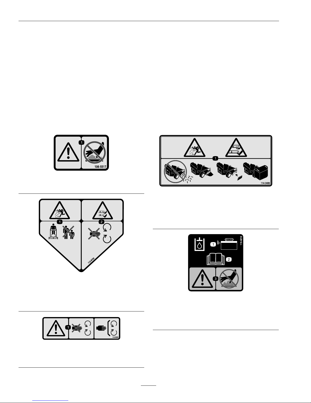
112-8760
1.Thrownobjecthazard—keepbystandersasafedistance
fromthemachine.
2.Cutting/dismembermentofhandorfoot—stayaway
frommovingparts.
112-9028
1.Warning—stayawayfrommovingparts;keepallguards
inplace.
114-3489
1.Thrownobjecthazard;cutting/dismemberment
hazard—donotoperatethemachinewiththedischarge
openinguncovered;alwaysoperatethemachinewith
thereardischargedeector,dischargecoverorgrass
collectorinstalled.
115-4212
1.Hydraulicoillevel3.Warning—donottouch
thehotsurface.
2.ReadtheOperator's
Manual.
10
Page 11
Safety
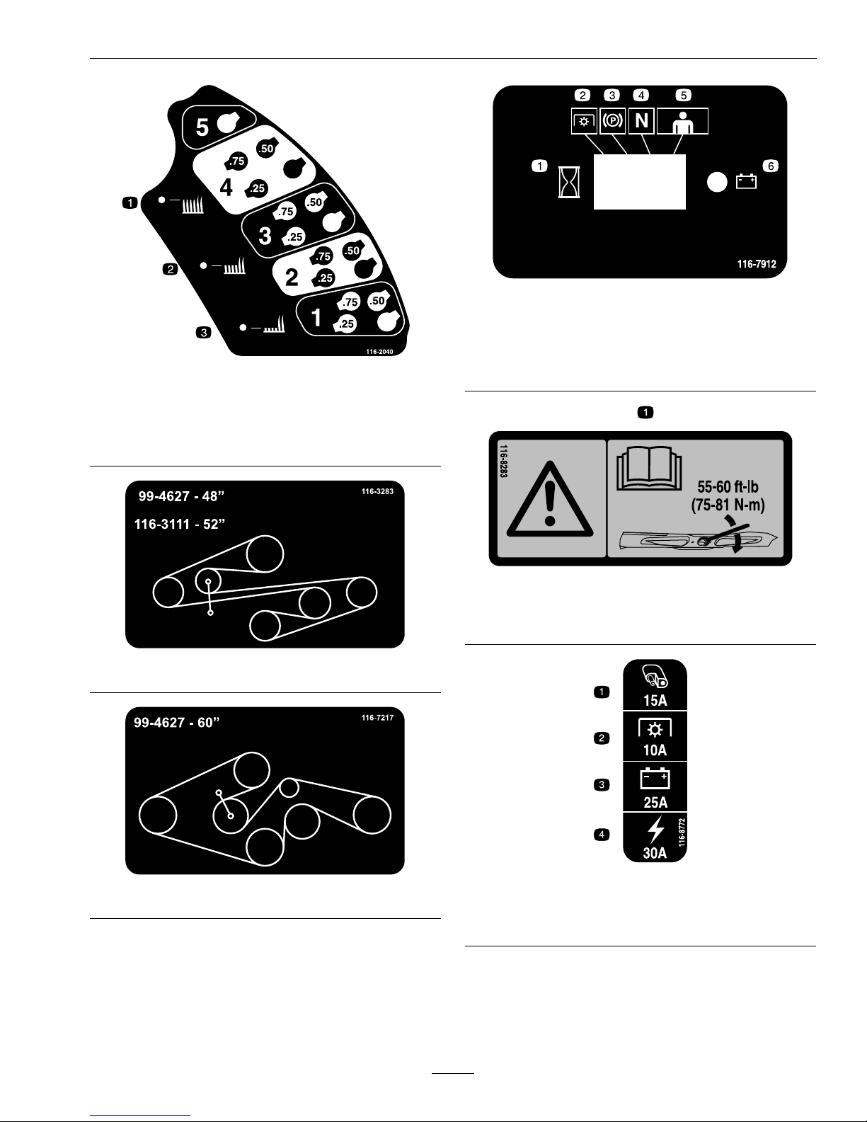
116-2040
1.Heightofcut(HOC)high
3.Heightofcut(HOC)-low
2.Heightofcut(HOC)medium
116-3283
116-7217
116-7912
1.Interval4.Neutral
2.PowerT ake-off(PTO)5.Operatorpresence
control
3.Parkingbrake6.Battery
116-8283
1.Warning—readtheOperator'sManualforinstructions
ontorquingthebladebolt/nutto55-60ft-lb(75-81N-m).
116-8772
1.Accessory,15A
3.Charge,25A
2.PTO,10A
4.Main,30A
11
Page 12
Safety
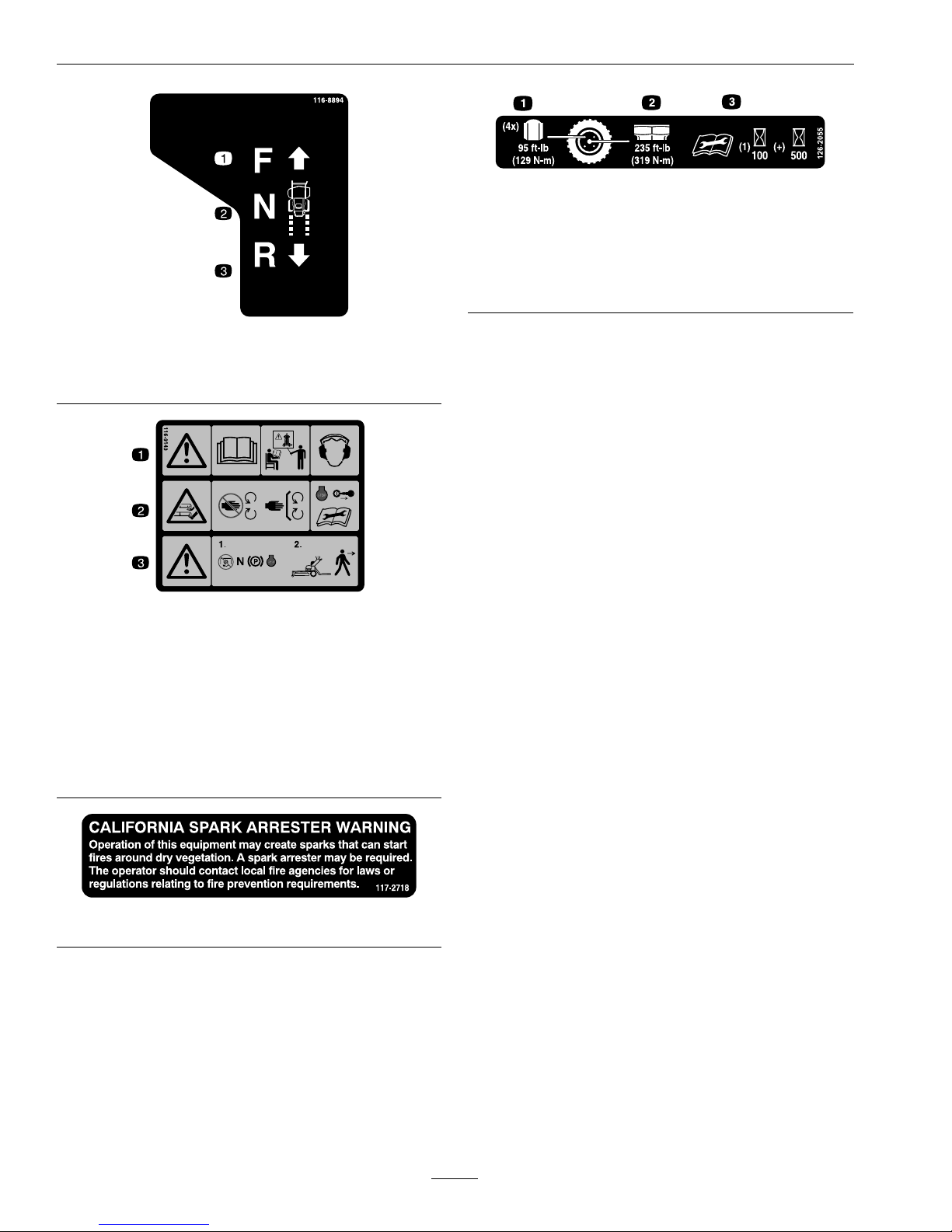
116-8894
1.Motioncontrol—forward
3.Motioncontrol—reverse
2.Motioncontrol—neutral
116-9143
1.Warning-ReadtheOperator’sManual.DoNotoperate
thismachineunlessyouaretrained.Wearhearing
protection.
2.Warning-Stayawayfrommovingparts;keepallguards
inplace.Stopengineandremovekeybeforeadjusting,
servicing,orcleaning.
3.Warning-DisengagePTO,shiftspeedcontroltoneutral,
andengageparkingbrakebeforeleavingtheoperator’s
position.
117–2718
126-2055
1.Wheellugnuttorque95ft-lb(129N-m)(4x)
2.Wheelhubnuttorque235ft-lb(319N-m)
3.ReadandunderstandtheOperator’smanualbefore
performinganymaintenance,checktorqueafterrst
100hoursthenevery500hoursthereafter.
12
Page 13
Safety
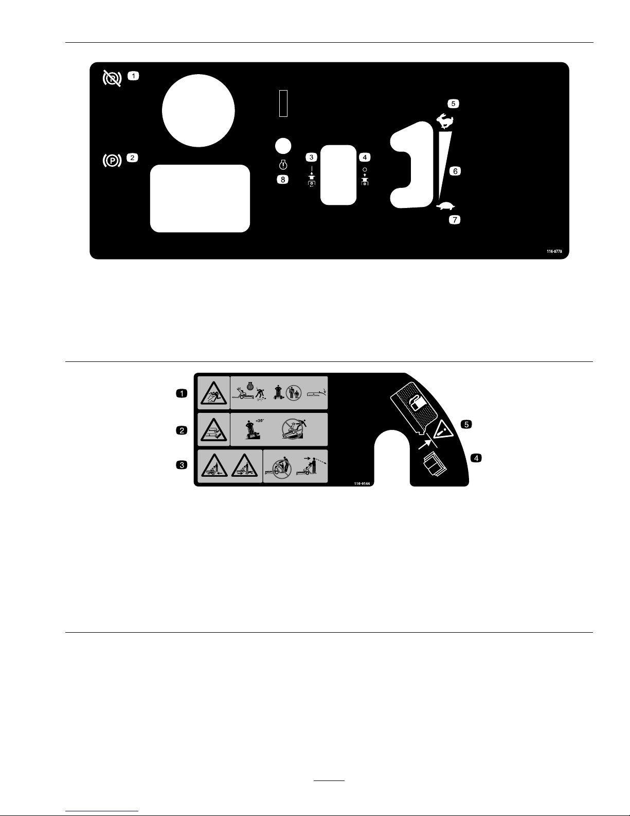
116-8778
EFIUnits
1.Parkingbrake-disengage
5.Throttle-fast
2.Parkingbrake-engaged
6.Continuousvariablesetting
3.PTO-on
7.Throttle-slow
4.PTO-off8.Checkengine
116-9144
1.Thrownobjecthazard-Pickupobjectsthatcouldbethrown
bymower.DoNotoperatewhenpeopleandpetsarein
thearea.Keepdeectorinplace.
4.ReadtheOperator’smanual.
2.Cutting/dismembermenthazard-DoNotoperateonslopes
greaterthan20degrees.DoNotmowwetslopes-use
extremecautionwhenoperatingonslopes;mowacross
slopesnotupanddown.
5.Filltobottomofllerneck;warning-DoNotoverllthetank.
3.Crushing/dismembermenthazardofbystanders-DoNot
carrypassengers,lookforwardanddownwhenoperating
themachine,lookbehindanddownwhenreversing.
13
Page 14
Safety
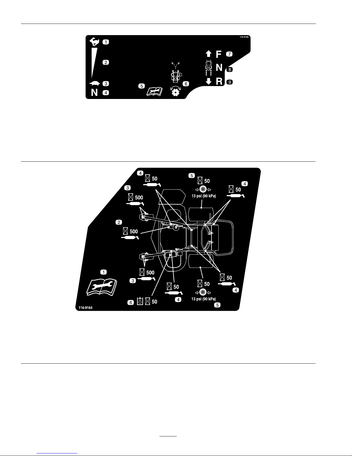
116-9145
1.Speedcontrol–fast
6.Turnknobtoadjusttracking
2.Continuousvariablespeed7.Motioncontrol–forward
3.Speedcontrol–slow
8.Motioncontrol–neutral
4.Speedcontrol–neutral
9.Motioncontrol–reverse
5.Readtheinstructionsbeforeservicingorperforming
maintenance
116-9164
1.ReadtheOperator’sManualbeforeperformingan
maintenance
4.Greaselinkagepivots(7)every50hours
2.Greasethebeltidlerevery500hours5.Checktirepressureevery50hours
3.Greasefrontcasterpivotsandwheelbearingsevery500
hours
6.Checkhydraulicoillevel(Onlyuserecommendedhydro
oil)
14
Page 15
Safety
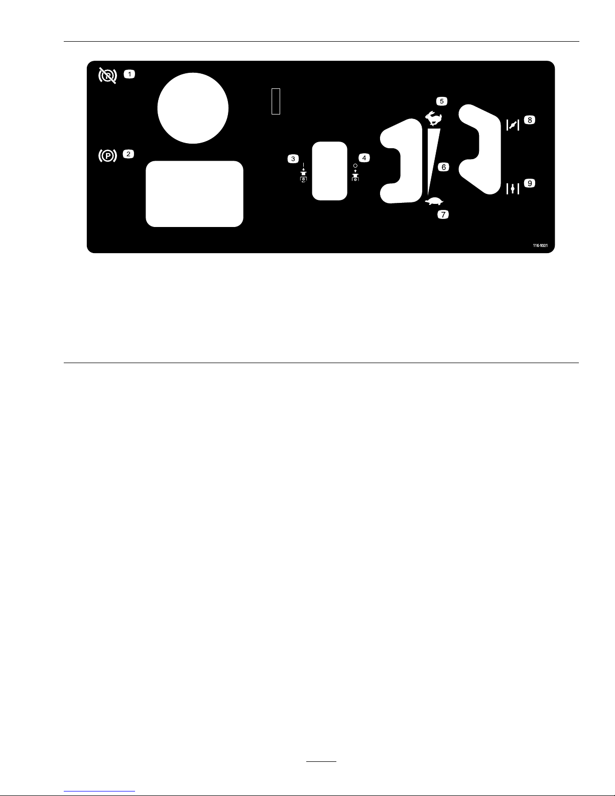
116-9321
AllUnitsExceptEFI
1.Parkingbrake–disengaged
6.Continuousvariablesetting
2.Parkingbrake–engaged7.Throttle–slow
3.PTO–on8.Choke–on
4.PTO–off9.Choke–off
5.Throttle–fast
15
Page 16

Specications
Specications
ModelNumbers
SerialNos:315,000,000andHigher
VTX651GKA48400;VTX730EKC52400;VTX740EKC60400
Systems
Engine
•EngineSpecications:SeeyourEngineOwner’s
Manual
•EngineOilType:Exmark4–CyclePremium
EngineOil
•RPM:FullSpeed:3600±100RPM(NoLoad)
FuelSystem
•Capacity:8.0gal.(30.2L)
•FuelRecommendations:
–Forbestresults,useonlyclean,fresh,unleaded
gasolinewithanoctaneratingof87orhigher
((R+M)/2ratingmethod).
–Oxygenatedfuelwithupto10%ethanolor
15%MTBEbyvolumeisacceptable.
–DoNotuseethanolblendsofgasoline(such
asE15orE85)withmorethan10%ethanol
byvolume.Performanceproblemsand/or
enginedamagemayresultwhichmaynotbe
coveredunderwarranty.
–DoNotusegasolinecontainingmethanol.
–DoNotstorefueleitherinthefueltankor
fuelcontainersoverthewinterunlessafuel
stabilizerisused.
–DoNotaddoiltogasoline.
•FuelFilter:
–Kawasaki:
KawasakiP/N49019-0014
–KohlerEFI:
KohlerP/N2505042
•FuelShut-OffValve:1/4turn
ElectricalSystem(ElectricStart)
•ChargingSystem:FlywheelAlternator
•ChargingCapacity:
Kawasaki:15amps
KohlerEFI:20amps
•BatteryType:BCIGroupU1
•BatteryVoltage:12Volt
•Polarity:NegativeGround
•Fuses:
–30ampmainfuse
–25ampchargingsystemfuse
–10ampPTOfuse
–15ampaccessoryfuse
SafetyInterlockSystem
•LCDindicatorsappearfortheparkbrake,drive
levers,andoperatorpresenceinthemessage
displayonthefrontcontrolpanel.
Note:BecausethePTOmustbedisengaged
tostarttheengine,theLCDindicatorwillnot
illuminateatthistime.
•PTOmustbedisengagedandspeedcontrollever
inneutraltostartengine.(Itisnotnecessaryfor
theoperatortobeontheplatformtostartthe
engine.)
•MowerbladeswillstopifboththeOPClevers
arereleased.
•Enginewillstopifthespeedcontrolleveris
movedfromtheneutralpositionwiththepark
brakeengaged.
OperatorControls
SteeringControl:Fingertipdrivecontrollevers
provideindependentspeedcontrol,brakingand
neutraltoeachdrivewheelformovingforwardor
reverse,stopping,andpowerturning.
Transmission
•TwoHydroGearvariabledisplacementhigh
efciencypumpsindependentlycoupledtotwo
highefciencyParker/Rosswheeldrivemotors.
16
Page 17

Specications
•HydraulicOil:UseExmarkPremiumHydroOil.
•HydraulicOilCapacity:2.4qt.(2.2L)
•HydraulicFilterisreplaceablecartridgetype.
P/N109-4180:25microns,10psibypass
(Summeruseabove32°F(0°C))
P/N1-523541:40microns,18psibypass(Winter
usebelow32°F(0°C))
•Speeds:
–0-8.0mph(13km/hr)forward.
–0-4.0mph(6km/hr)reverse.
•Drivewheelreleasevalvesallowmachinetobe
movedwhenengineisnotrunning.
WheelDriveSystem
DrivewheelsaredirectcoupledtoParkerwheeldrive
motorswith11/4inch(31.8mm)taperedshaft.
Tires&Wheels
Drive
FrontCaster
Pneumatic
(Air-Filled)
SemiPneumatic
Quantity
22
Tread
K500
Smooth
Size20x10.50–811x4.00-5
PlyRating
4
Pressure
13psi
(90kPa)
CuttingDeck
•CuttingWidth:
–48inchDeck:48inches(121.9cm)
–52inchDeck:52inches(132.1cm)
–60inchDeck:60inches(152.4cm)
•Discharge:Side
•BladeSize:(3ea.)
–48inchDeck:16.25inches(41.3cm)
–52inchDeck:18.00inches(45.7cm)
–60inchDeck:20.50inches(52.1cm)
•BladeSpindles:Solidsteelspindleswith1.00inch
(25.4mm)I.D .bearings.
•DeckDrive:
–Electricclutchmountedonengineshaft.
–Bladesdrivenbyonebelt(w/self-tensioning
idlers).
•Deck:Fulloatingdeckisattachedtosupport
frame,removableforservice.Deckdesignallows
forbagging,mulchingorsidedischarge.
•DeckDepth:
–48inchDeck:5.5inches(14.0cm)
–52inchDeck:5.5inches(14.0cm)
–60inchDeck:5.5inches(14.0cm)
•CuttingHeightAdjustment:Adjustsfrom1inch
(2.5cm)to5.5inches(14cm)in1/4inch(6.4
mm)increments.
•MulchingKit:Optional
•Bagger:Optional
Dimensions
OverallWidth:
48inch
Deck
52inch
Deck
60inch
Deck
Deector
Up
51.8inches
(131.6cm)
56.3inches
(143.0cm)
63.9inches
(162.3cm)
Deector
Down
59.6inches
(151.4cm)
64.8inches
(164.6cm)
72.8inches
(184.9cm)
OverallLength:
48inch
Deck
52inch
Deck
60inch
Deck
Platform
Up
60.5inches
(153.7cm)
60.5inches
(153.7cm)
62.4inches
(158.5cm)
Platform
Down
74.0inches
(188.0cm)
74.0inches
(188.0cm)
75.9inches
(192.8cm)
OverallHeight:
48inchDeck52inchDeck60inchDeck
50.0inches
(127.0cm)
50.0inches
(127.0cm)
50.0inches
(127.0cm)
TreadWidth:(OutsidetoOutsideof
Tires,Widthwise)
48inchDeck52inchDeck60inchDeck
46.5inches
(118.1cm)
46.5inches
(118.1cm)
50.5inches
(128.3cm)
17
Page 18
ProductOverview
CurbWeight:
48inchDeck52inchDeck60inchDeck
855lb
(388kg)
875lb
(397kg)
883lb
(401kg)
Note:Weightswillvaryslightlydependingonengine.
TorqueRequirements
BoltLocation
Torque
CutterHousingSpindle
Nut
130-160ft-lb
(176-217N-m)
BladeMountingBolt
(lubricatewithanti-seize)
50-60ft-lb(68-81N-m)
ClutchMountingBolt
50-60ft-lb(68-81N-m)
EngineDeck/Mower
DeckSupportMount
Bolts
30-35ft-lb(41-47N-m)
EngineMountingBolts
Kawasaki
Kohler
30-35ft-lb(41-47N-m)
27-33ft-lb(37-45N-m)
WheelLugNuts
85-105ft-lb(115-142
N-m)
WheelHubNuts175-225ft-lb
(237-305N-m)
WheelMotorMounting
Bolts
67-83ft-lb(91-113N-m)
HydroPumpRelease
Valves
110-130in-lb(12-15N-m)
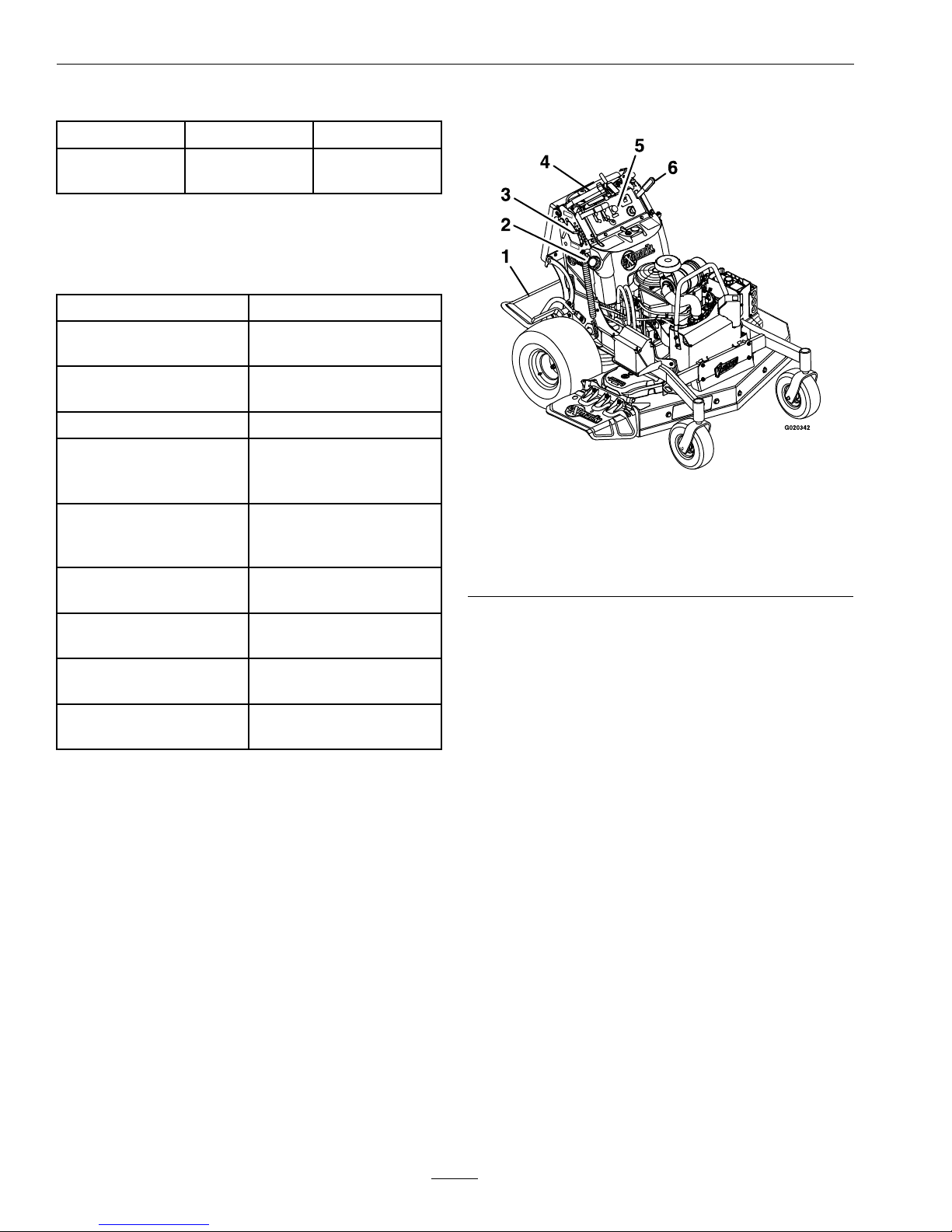
ProductOverview
Figure3
1.Platform
4.Drivelevers
2.FuelCap5.EngineControls
3.Height-of-Cut
Adjustment
6.ParkBrakeLever
18
Page 19

Operation
Operation
Note:Determinetheleftandrightsidesofthe
machinefromthenormaloperatingposition.
Controls
OperatorPresenceControl(OPC)
Levers
Locatedontheupperhandleassemblydirectlybelow
thehandlegrips(seeFigure4).
Figure4
LHupperhandleassemblyshown
1.Neutrallocklatch
3.OPCLever
2.Rotateneutrallocklatch4.Driveleverinneutral
position
Whentheseleversaredepressed,theOPCsystem
sensesthattheoperatorisinthenormaloperator's
position.
Note:TheLCDindicatorappearsinthemessage
displayonthefrontconsolewhentheOPCleversare
depressed(seeFigure5andFigure7).
Whentheleversarereleased,theOPCsystem
sensesthattheoperatorhasmovedfromthenormal
operatingposition.
•Iftheleversarereleasedwiththespeedcontrol
notinneutral,theenginewillkill(withorwithout
PTOengaged).
•Iftheleversarereleasedwiththespeedcontrolin
neutralandthePTOengaged,themowerblades
disengagebuttheengineremainsrunning.
DriveLevers
Locatedoneachsideoftheupperhandleassembly
aheadofandbelowthehandlegrips(seeFigure4).
Theseleversindividuallycontrolthespeedand
directionofeachdrivewheel.Whenthespeed
controlleverismovedoutoftheneutralposition
andtheneutrallocklatchesaremovedintothedrive
positionandthedriveleversarereleased,thedrive
wheelsareengagedintheforwarddirection.
Squeezingthelefthandand/orrighthandlever
causesthelefthandand/orrighthanddrivewheel
respectivelytoslowdown,stop,orreverse,depending
onhowfareachdriveleveris“squeezed”.Squeezing
thedriveleversbeyondtheneutralpositioncauses
thedrivewheelstoengageinthereversedirection
regardlessofthepositionoftheneutrallocklatches
andthespeedcontrollever.
NeutralLockLatches
Locatedontheupperhandleassemblyontheends
ofthehandlegrips(seeFigure4).
Theselatchesallowtheoperatortolockthedrive
leversina“neutral”positionwherethedrivewheels
arenotengagedineitheraforwardorreverse
direction.
ChokeControl(AllUnitsExcept
KohlerEFI)
LocatedontheRHsideofthefrontcontrolconsole
(seeFigure5).
Thechokeisusedtoaidinstartingacoldengine.
Movingthechokeleverforwardwillputthechokein
the“ON”positionandmovingthechokelevertothe
rear,tothedetent,willputthechokeinthe“OFF”
position.DoNotrunawarmenginewithchokein
the“ON”position.
19
Page 20

Operation
Figure5
1.Platformlatch
9.Ignitionswitch
2.Choke
10.Fuelgauge
3.RHhandlegripwith
neutrallocklatch
11.PTOengagementswitch
4.Trackingknob12.Throttle
5.Speedcontrollever13.Decklifthandle
6.LHhandlegripwith
neutrallocklatch
14.Fuelcap
7.Parkbrakelever
15.Height-of-cutpin
8.Messagedisplay
ThrottleControl
LocatedontheRHsideofthefrontcontrolconsole
(redlever)(seeFigure5).
Thethrottleisusedtocontrolenginespeed.Moving
thethrottleleverforwardwillincreaseenginespeed
andmovingthethrottlelevertotherearwilldecrease
enginespeed.Movingthethrottleforwardintothe
detentisfullthrottle.
SpeedControlLever
Locatedinmiddleofcontrolconsole(seeFigure5).
Thespeedcontrollevercontrolsthemaximum
forwardspeedandisinnitelyvariablefromneutral
0–8.0mph(12.9km/hr).
Parkbrakemustbedisengagedtomovespeedcontrol
outofneutralorenginewillkill.
Note:TheLCDindicatorappearsinthemessage
displayonthefrontconsolewhenthespeedcontrol
leverisintheneutralposition(seeFigure5and
Figure7).
ParkBrakeLever
Locatedonleftsideofunit(seeFigure5).
Thebrakeleverengagesaparkingbrakeonthedrive
wheels.
Note:TheLCDindicatorappearsinthemessage
displayonthefrontconsolewhentheparkbrakeis
engaged(seeFigure5andFigure7).
Toengagethebrake,pulltheleverrearwardandto
therighttopositionintotheengagedposition.
Torelease,pullthebrakeleverbackandovertothe
left,positionintotheslotandpushtheleverforward.
Whenparkingonasteepslope,thewheelsmustbe
chockedorblockedinadditiontothebrakebeing
engaged.Theunitmustbetieddownandbrake
engagedwhentransporting.
Parkbrakemustbedisengagedbeforemovingspeed
controloutofneutralorenginewillkill.
IgnitionSwitch
LocatedontheLHsideofthefrontcontrolconsole
(seeFigure5).
Theignitionswitchisusedtostartandstopthe
engine.Theswitchhasthreepositions“OFF”,“ON”
and“START”.Insertkeyintoswitchandrotate
clockwisetothe“ON”position.Rotateclockwiseto
thenextpositiontoengagethestarter(keymustbe
heldagainstspringpressureinthisposition).Allow
thekeytoreturntothe“ON”positionimmediately
aftertheenginestarts.
Figure6
1.Off3.Start
2.On
Note:T ostarttheengine,operatormusthavespeed
controlleverinneutral,OPCleversdepressed,and
thePTOdisengaged.(Itisnotnecessaryforthe
operatortobeontheplatform.)
20
Page 21

Operation
HourMeter
LocatedontheLHsideofthefrontcontrolconsole
inthemessagedisplay(seeFigure5andFigure7).
Thehourmeterrecordsthenumberofhoursthat
theenginehasrun.
Figure7
1.LCDIndicators
2.Lowvoltageindicatorlight
3.Hour/Voltagedisplay
Thehourmeterisrecordingwhenthedecimalpoint
isashinginHour/Voltagedisplay.
Hoursaredisplayedwhenthekeyisofforwhenthe
machineisrunning.
Note:Iftheignitionkeyisturnedtothe“ON”
positionforafewsecondsbeforecrankingtheengine,
thebatteryvoltagewilldisplayintheareawherethe
hoursarenormallydisplayed.
Note:TheLCDindicatorsappearwheneach
controlmeetsthe“safetostart”mode.Becausethe
PTOmustbedisengagedtostarttheengine,the
LCDindicatorwillnotilluminateatthistime.
FuelShut-OffValve
LocatedontheRHsideofthecontroltowerbehind
thekneecushionforKawasakiunits.Locatedon
theLHsideofthemachine,towardstherearofthe
engine,onKohlerunits.
Thefuelshut-offvalveisusedtoshutoffthefuel
whenthemachinewillnotbeusedforafewdays,
duringtransporttoandfromthejobsite,andwhen
parkedinsideabuilding.
Alignvalvehandlewiththefuellinetoopen.Rotate
90°toclose.
FuelGauge
Locatedonthetopleftsideofthetank(seeFigure5).
Thefuelgaugemonitorstheamountoffuelinthe
tank.
DriveWheelReleaseValves
Locatedontherightfrontcornerofthehydrostatic
pumps.
Drivewheelreleasevalvesareusedtoreleasethe
hydrostaticdrivesystemtoallowthemachinetobe
movedbyhandwithouttheenginerunning.
Witha5/8wrench,turnbothvalvesoneturn
counterclockwisetoreleasethedrivesystem.
Turnclockwisetoresetthedrivesystem.Torqueto
110-130in-lb(12-15N-m).DoNotovertighten.
DoNottowmachine.
PTOEngagementSwitch
Locatedonfrontcontrolpanel(seeFigure5).
Switchmustbepulledout(up)toengagetheblades.
Switchispushedintodisengagetheblades.
TheLCDindicatorwillappearwhenthePTOswitch
isengaged(seeFigure7).
LowVoltageIndicator
Locatedonthefrontcontrolpanelinthemessage
display(seeFigure5andFigure7).
Alowvoltagecondition(lessthan12.3volts)exists
whenthelowvoltageindicatorlightappearsonthe
messagedisplaywhiletheengineisrunning.
Iftheignitionkeyisturnedtothe“ON”positionfor
afewsecondsbeforecrankingtheengine,thebattery
voltagewilldisplayintheareawherethehoursare
normallydisplayed.
Note:Theindicatornormallyappearswhenthe
engineisoffandthekeyswitchisturnedtothe
“ON”position.
DeckLiftHandle
LocatedontheRHofthefrontcontrolpanel.
Pullthehandlerearwardtoraisethecuttingdeck.
Allowthehandletomoveforwardtolowerthe
cuttingdecktothecutheightthathasbeenset.
21
Page 22

Operation
Pullthehandlerearwardandtotherighttolatchthe
cuttingdeckintotheraisedtransportposition(see
Figure5).
ElectronicControlUnitMalfunction
Indicator
KohlerEFIUnitsOnly:
Theelectroniccontrolunit(ECU)continuously
monitorsoperationoftheEFIsystem.Ifaproblem
orfaultwithinthesystemisdetected,themalfunction
indicatorlight(MIL)isilluminated.TheMILis
thelightlocatedintheconsolepaneltotheleftof
thePTOswitch.Followthetroubleshootingsteps
outlinedintheKohlerengineoperator’smanualifthe
MILisilluminated.
Pre-Start
Fillfueltankonlevelground.SeeFuel
RecommendationsintheSpecicationssectionfor
additionalgasolineinformation.
DoNotaddoiltogasoline.
DoNotoverllfueltank.Fillthefueltanktothe
bottomofthellerneck.Theemptyspaceinthe
tankallowsgasolinetoexpand.Overllingmayresult
infuelleakageordamagetotheengineoremission
system.
Makesureyouunderstandthecontrols,their
locations,theirfunctions,andtheirsafety
requirements.
RefertotheMaintenancesectionandperformallthe
necessaryinspectionandmaintenancesteps.
Foroperationonhillyterrain,afrontweightkit
accessory(P/N116-2935)maybeaddedtoenhance
stabilityandcontrol.Seetherecommendations
below:
•Operatorlessthan200lb(91kg)—noadditional
weights.
•Operator200–275lb(91-125kg)—useonefront
weightkit.
•Operatorover275lb(125kg)—useone
frontweightkitplus2additionalweights(P/N
103-2455-01).
OperatingInstructions
OpentheFuelShut-OffValve
Rotatethevalveandalignwiththefuellinetoopen.
StartingtheEngine
1.Onacoldengine,placethethrottlemidway
betweenthe“Slow”and“Fast”positionsand
placethechokeinthe“On”position(except
onKohlerEFIunits).Onawarmengine,place
thethrottlelevermidwaybetween“Slow”and
“Fast”positionsandleavethechokeinthe“Off”
position.
2.Movethespeedcontrollevertoneutral.
3.Turnignitionswitchto“Start”position.Release
theswitchassoonastheenginestarts.
4.Onacoldengine,graduallyreturnchoketothe
“Off”positionafterenginestartsandwarmsup.
Important:Donotcranktheengine
continuouslyformorethantensecondsat
atime.Iftheenginedoesnotstart,allowa
60secondstartercool-downperiodbetween
startingattempts.Failuretofollowthese
guidelinescanburnoutthestartermotor.
Note:Itishelpfultohavetheleftandright
neutrallocklatcheslockedinneutralwhenstarting
theengine.RefertoNeutralLockLatches
sectioninControls.
EngagingthePTO
DANGER
Therotatingbladesunderthemowerdeckare
dangerous.Bladecontactcancauseserious
injuryorkillyou.
DoNotputhandsorfeetunderthemoweror
mowerdeckwhenthebladesareengaged.
22
Page 23

Operation
DANGER
Anuncovereddischargeopeningwillallow
objectstobethrowninanoperator’sor
bystander’sdirection.Also,contactwiththe
bladecouldoccur.Thrownobjectsorblade
contactcancauseseriousinjuryordeath.
Neveroperatethemowerwiththedischarge
deectorraised,removed,oralteredunlessthere
isagrasscollectionsystemormulchkitinplace
andworkingproperly.
ThePTOswitchengagesthecuttingblades.Besure
thatallpersonsareclearofmowerdeckanddischarge
areabeforeengagingthePTO.
1.Setthrottleto“MIDWAY”position.
2.PullthePTOswitchoutwardtothe“ROTATE”
positiontoengagetheblades.
3.Placethethrottleinthe“FAST”positiontobegin
mowing.
DisengagingthePTO
1.Setthethrottletothe“MIDWAY”position.
2.PushthePTOswitchintothe“STOP”position
todisengagetheblades.
StoppingtheEngine
1.Bringtheunittoafullstop.
2.Lockdriveleversinneutral.
3.DisengagethePTO.
4.Movespeedcontrollevertoneutral.
5.Engagetheparkingbrake.
6.Placethethrottlemidwaybetweenthe“SLOW”
and“FAST”positions.
7.Allowtheenginetorunforaminimumof15
seconds,thenturntheignitionswitchtothe
“OFF”positiontostoptheengine.
8.Removethekeytopreventchildrenorother
unauthorizedpersonsfromstartingengine.
9.Closethefuelshut-offvalvewhenthemachine
willnotbeinuseforafewdays,when
transporting,orwhentheunitisparkedinside
abuilding.
DrivingtheMachine
DriveLever/NeutralLockLatchOperation
Tolockthedriveleversin“neutrallock”,squeezethe
driveleverstothe“neutral”position(DoNotsqueeze
thedriveleversallthewaybackasthiswillcausethe
drivewheelstogointofullreversedirection).See
Figure8position1.Placethumbsontheinnerlobe
oftheneutrallocklatchesandrotatethemunder
thedriveleversintothe“neutrallock”position.See
Figure8position2.Releasethedrivelevers.
CAUTION
Iftheneutrallocklatchesarenotcompletely
engagedthedriveleverscouldunexpectedlyslip
intotheforwarddriveposition.Ifthedrivelevers
slipintothedrivepositiontheunitcouldlurch
forwardandcauseinjuryorpropertydamage.
Besurethedriveleversarepasttherollerand
securelyseatedatthebottomoftheneutrallock
latches.
Toplacethedriveleversinthe“forward”position,
slightlysqueezethedriveleverswhileplacingthumbs
ontheouterthumblobeoftheneutrallocklatches
(ortheindexngeronthefrontlobe)androtatethem
fromunderthedrivelevers.Slowlyandcarefully
releasethedrivelevers.SeeFigure8position3.
Toplacethedriveleversinthe“reverse”position,
squeezethedriveleverspasttheneutralposition.See
Figure8position4.
Figure8
1.DriveLeverinneutral
position
3.DriveLeverinforward
position
2.DriveLeverlockedin
neutralposition
4.DriveLeverinreverse
position
DrivingForward
1.Releasetheparkingbrake.
23
Page 24

Operation
2.Withdriveleverslockedin“neutral”,shiftspeed
controllevertodesiredforwardspeed.
3.Slowlysqueezeandholdbothdriveleversin
theneutralpositionandrotatebothneutrallock
latchesfromtheneutrallockpositiontothe
forwardposition.
Note:DoNotsqueezebothdriveleversallthe
wayback.Thiswillcausethedrivewheelsto
engageinthereversedirection.
4.Tomoveforwardinastraightline,smoothly
releasebothdriveleverstoengagedrivewheels.
Toturnleftorright,squeezetherighthanddrive
levertoturnrightandthelefthanddrivelever
toturnleft.
Tomakea“zeroturn”,squeezeeithertheleft
handortherighthanddriveleverbackintothe
reversepositionwhiletheoppositedriveleverisin
aforwardpositionatanequalbutoppositespeed.
Note:Forsmoothoperationofthismachine,
avoidquick,jerkymovementsofthedrivelevers.
Movethedriveleverssmoothlyanddeliberately .
Tostop,squeezedriveleversbacktothe“neutral”
position.Movetheneutrallocklatchesintothe
“neutrallock”positionandreleasedrivelevers.
Movethespeedcontrollevertotheneutral
position.
5.Iftheunittrackstoonesideortheother,turnthe
quicktrackknob.Turntheknobrightto“steer”
right,turntheknobleftto“steer”left.
DrivinginReverse
Tomoverearwardinastraightline,squeezedrive
leversintothereverseposition.
Toturnleftorright,squeezetherighthanddrivelever
toturnleftandthelefthanddrivelevertoturnright.
Tomakea“zeroturn”,squeezeeitherthelefthand
ortherighthanddriveleverbackintothereverse
positionwhiletheoppositedriveleverisinaforward
positionatanequalbutoppositespeed.
Note:Forsmoothoperationofthismachine,avoid
quick,jerkymovementsofthedrivelevers.Movethe
driveleverssmoothlyanddeliberately .
Tostop,squeezedriveleversbacktothe“neutral”
position.Movetheneutrallocklatchesintothe
“neutrallock”positionandreleasedrivelevers.Move
thespeedcontrollevertotheneutralposition.
OperatingthePlatform
Themachinecanbeusedwiththeplatforminthe
upordownposition.Itistheoperator'spreference
onwhichpositiontouse.
WARNING
Theoperatorplatformisheavyandmaycause
injurywhenloweringandraisingtheoperator
platform.Theplatformmaysuddenlydropifnot
supportedwhenthelatchpinispulledout.
•DoNotputyourhandsorngersinthe
platformpivotareawhenloweringorraising
theoperatorplatform.
•Makesuretheplatformissupportedwhen
thelatchpinispulledout.
•Makesurethelatchsecurestheplatform
whenfoldingitintheupposition.Pushit
tightagainstthecushionforthelatchpinto
lockintoplace.
OperatingtheMachinewiththe
PlatformUp
Operatingthemachinewiththeplatformupis
recommendedwhen:
•Mowingneardrop-off's
•Mowingsmallareaswherethemachineistoolong
•Areaswithlowoverhangingbranchesorobstacles
•Loadingthemachinefortransport
•Unloadingthemachineaftertransport
•Drivinguporbackingdownslopesorramps.
•Turningintightareaswhereplatformmaycontact
obstacles.
Toraisetheplatform,pullthebottomupwardand
pushittightagainstthecushion.Thelatchpinknob
willsnapinwardtolocktheplatformintoplace(see
Figure9).
24
Page 25

Operation
Figure9
1.Platform
2.Raiseupward
3.Latchpinknobsnapsinward
OperatingtheMachinewiththe
PlatformDown
Operatingthemachinewiththeplatformdownis
recommendedwhen:
•Mowingmostareas
•Drivingdownslopes
Tolowertheplatform,pushtheplatformforward
againstthecushiontoreleasepressureonthelatch
pin,pulltheknoboutward,andlowertheplatform
(seeFigure10).
Figure10
1.Pulllatchpinknoboutward
2.Platform
3.Lower
AdjustingtheCuttingHeight
Thecuttingheightofthemowerdeckisadjustedin
1/4inch(6.4mm)increments.
1.Stopthemachineandmovethelockdrivelevers
inneutral.
2.DisengagethePTO.
3.Movespeedcontrollevertoneutral.
4.Raiseandlockthedecktothetransportposition.
Thedeckisraisedbypullingthedecklifthandle
rearwardandtotherighttoplaceitintothe
transportlockposition.
Figure11
1.Transportlockposition
3.Decklifthandle
2.RHhandleassembly
Note:Whenchangingthecuttingheight
positions,alwayscometoacompletestop
anddisengagethePTO.
5.Inserttheheightadjustmentpinintothehole
correspondingtothedesiredcuttingheight.
Seethedecalonthesideofthedeckliftplatefor
cutheights(referenceFigure12).
6.Pullthedecklifthandlerearwardandtotheleft
andslowlyallowthedecktolowertothecutting
height.
25
Page 26

Operation
Figure12
1.Heightadjustmentpin
3.Decklifthandle
2.Heightofcutholes
Transporting
TransportingaUnit
Useaheavy-dutytrailerortrucktotransportthe
machine.Lockbrakeandblockwheels.Securely
fastenthemachinetothetrailerortruckwithstraps,
chains,cable,orropes.Ifpossible,bothfrontand
rearstrapsshouldbedirecteddownandoutward
fromthemachine.Besurethatthetrailerortruck
hasallnecessarylightingandmarkingasrequiredby
law .Secureatrailerwithasafetychain.
CAUTION
Thisunitdoesnothaveproperturnsignals,
lights,reectivemarkings,oraslowmoving
vehicleemblem.Drivingonastreetorroadway
withoutsuchequipmentisdangerousand
canleadtoaccidentscausingpersonalinjury.
Drivingonastreetorroadwaywithoutsuch
equipmentmayalsobeaviolationofStatelaws
andtheoperatormaybesubjecttotrafctickets
and/ornes.
DoNotdriveaunitonapublicstreetorroadway .
WARNING
Loadingaunitonatrailerortruckincreases
thepossibilityofbackwardtip-over.Backward
tip-overcouldcauseseriousinjuryordeath.
•Useextremecautionwhenoperatingaunit
onaramp.
•Useonlyasingle,fullwidthramp;DoNot
useindividualrampsforeachsideoftheunit.
•Ifindividualrampsmustbeused,useenough
rampstocreateanunbrokenrampsurface
widerthantheunit.
•DoNotexceeda20degreeanglebetween
rampandgroundorbetweenrampandtrailer
ortruck.
•Avoidsuddenaccelerationwhiledrivingunit
uparamptoavoidtippingbackward.
•Avoidsuddendecelerationwhilebackingunit
downaramptoavoidtippingbackward.
LoadingaUnit
Useextremecautionwhenloadingunitsontrailersor
trucks.Onefullwidthrampthatiswideenoughto
extendbeyondthereartiresisrecommendedinstead
ofindividualrampsforeachsideoftheunit.With
theplatformup,afullwidthrampprovidesasurface
towalkonbehindtheunit.Ifitisnotpossibletouse
onefullwidthramp,useenoughindividualrampsto
simulateafullwidthcontinuousramp.
Rampshouldbelongenoughsothattheangles
betweentherampandthegroundandtheramp
andthetrailerortruckdonotexceed20degrees.A
steeperanglemaycausemowerdeckcomponentsto
getcaughtastheunitmovesfromramptotrailer
ortruck.Steeperanglesmayalsocausetheunitto
tipbackward.Ifloadingonornearaslope,position
thetrailerortrucksoitisonthedownsideofthe
slopeandtherampextendsuptheslope.Thiswill
minimizetherampangle.Thetrailerortruckshould
beaslevelaspossible.
Important:DoNotattempttoturntheunit
whileontheramp,youmaylosecontroland
driveofftheside.
Avoidsuddenaccelerationwhendrivinguparamp
andsuddendecelerationwhenbackingdownaramp.
Bothmaneuverscancausetheunittotipbackward.
26
Page 27

Maintenance
Maintenance
Note:Determinetheleftandrightsidesofthemachinefromthenormaloperatingposition.
WARNING
Whilemaintenanceoradjustmentsarebeing
made,someonecouldstarttheengine.
Accidentalstartingoftheenginecouldseriously
injureyouorotherbystanders.
Removethekeyfromtheignitionswitch,engage
parkingbrake,andpullthewire(s)offthespark
plug(s)beforeyoudoanymaintenance.Also
pushthewire(s)asidesoitdoesnotaccidentally
contactthesparkplug(s).
WARNING
Theenginecanbecomeveryhot.Touchingahot
enginecancausesevereburns.
Allowtheenginetocoolcompletelybefore
serviceormakingrepairsaroundtheenginearea.
RecommendedMaintenanceSchedule(s)
MaintenanceService
Interval
MaintenanceProcedure
Aftertherst5hours
•Changetheengineoil.
Aftertherst100hours
•Checkthewheelhubtorquespecication.
•Checkthewheellugnuts.
Aftertherst250hours
•Changethehydrauliclteranduid.
Beforeeachuseordaily
•Checktheengineoillevel.
•Checkthemowerblades.
•Checkthesafetyinterlocksystem.
•Checkforloosehardware.
•Cleantheengineandexhaustsystemarea.
•Cleanthegrassanddebrisbuild-upfromthemachineandcuttingdeck.
•Cleanthegrassbuild-upfromunderthedeck.
Every50hours
•Checkthehydraulicoillevel.
•Checkthetirepressures.
•Checktheconditionofthebelts.
•Greasetheliftlinkagepivots.
•Checksparkarrester(ifequipped).
Every80hours
•Removeengineshroudsandcleancoolingns.
Every100hours
•Changetheengineoil.(Mayneedmoreoftenundersevereconditions.)
Every160hours
•Checkthesparkplugs.
Every250hours
•Replacetheprimaryaircleanerelement—checksecondaryaircleanerelement;replaceif
dirty.(Mayneedmoreoftenundersevereconditions.SeetheEnginemanualforadditional
information.)
27
Page 28

Maintenance
MaintenanceService
Interval
MaintenanceProcedure
Every500hours
•Replacethesecondaryaircleanerelement.(Mayneedmoreoftenundersevereconditions.
SeetheEnginemanualforadditionalinformation.)
•Changethehydrauliclteranduid(Every250hours/yearlyifusingMobil115W50)
•Checkthewheelhubtorquespecication.
•Checkthewheellugnuts.
Yearly
•Greasethefrontcasterpivots.
•Greasethedeckbeltidlerpivot.
•Lubricatethecasterwheelhubs.
PeriodicMaintenance
CheckEngineOilLevel
ServiceInterval:Beforeeachuseordaily
1.Stopengineandwaitforallmovingpartstostop.
Makesureunitisonalevelsurface.
2.Checkwithenginecold.
3.Cleanareaarounddipstick.Removedipstickand
wipeoiloff.Reinsertthedipstickandpushitall
thewaydownintothetube.DoNotscrewinto
place.Removethedipstickandreadtheoillevel.
4.Iftheoillevelislow ,wipeofftheareaaroundthe
oilllcap,removecapandaddoiltothe“FULL”
markonthedipstick.Exmark4-CyclePremium
EngineOilisrecommended;refertotheEngine
Owner'smanualforanacceptablealternative.Do
Notoverll.
Important:DoNotoperatetheenginewiththe
oillevelbelowthe“LOW”(or“ADD”)markon
thedipstick,oroverthe“FULL”mark.
CheckBatteryCharge
ServiceInterval:Asrequired
WARNING
CALIFORNIA
Proposition65Warning
Batteryposts,terminals,andrelated
accessoriescontainleadandlead
compounds,chemicalsknowntotheStateof
Californiatocausecancerandreproductive
harm.Washhandsafterhandling.
Allowingbatteriestostandforanextendedperiodof
timewithoutrechargingthemwillresultinreduced
performanceandservicelife.Topreserveoptimum
batteryperformanceandlife,rechargebatteriesin
storagewhentheopencircuitvoltagedropsto12.4
volts.
Note:Topreventdamageduetofreezing,battery
shouldbefullychargedbeforeputtingawayfor
winterstorage.
Checkthevoltageofthebatterywithadigital
voltmeterorwiththemessagedisplay.Iftheignition
keyisturnedtothe“on”positionforafewseconds,
thebatteryvoltagewillbedisplayedintheareawhere
thehoursarenormallydisplayed.Locatethevoltage
readingofthebatteryinthetableandchargethe
batteryfortherecommendedtimeintervaltobring
thechargeuptoafullchargeof12.6voltsorgreater.
Important:Makesurethenegativebatterycable
isdisconnectedandthebatterychargerusedfor
chargingthebatteryshouldhaveanoutputof
16voltsand7ampsorlesstoavoiddamaging
thebattery(seechartforrecommendedcharger
settings).ThisisespeciallyimportantonKohler
EFI(ElectronicFuelInjection)units.Failureto
dosomaydamagetheECU(ElectronicControl
Unit).
Voltage
Reading
Percent
Charge
Maximum
Charger
Settings
Charging
Interval
12.6or
greater
100%
16volts/7
amps
No
Charging
Required
12.4–12.675–100%
16volts/7
amps
30Minutes
12.2–12.450–75%
16volts/7
amps
1Hour
28
Page 29

Maintenance
Voltage
Reading
Percent
Charge
Maximum
Charger
Settings
Charging
Interval
12.0–12.225–50%
14.4volts/4
amps
2Hours
11.7–12.00–25%
14.4volts/4
amps
3Hours
11.7orless
0%
14.4volts/2
amps
6Hoursor
More
Important:ForKohlerEFIunits:Unplugthe
harnessfromtheECUbeforeperformingany
weldingontheequipment.
RecommendedJump
StartingProcedure
ServiceInterval:Asrequired
1.Checktheweakbatteryforterminalcorrosion
(white,green,orblue“snow”),itmustbecleaned
offpriortojumpstarting.Cleanandtighten
connectionsasnecessary.
CAUTION
Corrosionorlooseconnectionscancause
unwantedelectricalvoltagespikesatanytime
duringthejumpstartingprocedure.
DoNotattempttojumpstartwithlooseor
corrodedbatteryterminalsordamagetothe
engineorEFImayoccur.
DANGER
Jumpstartingaweakbatterythatiscracked,
frozen,haslowelectrolytelevel,oran
open/shortedbatterycell,cancausean
explosionresultinginseriouspersonalinjury.
DoNotjumpstartaweakbatteryifthese
conditionsexist.
2.Makesuretheboosterisagoodandfullycharged
leadacidbatteryat12.6voltsorgreater.Use
properlysizedjumpercables(4to6A WG)with
shortlengthstoreducevoltagedropbetween
systems.Makesurethecablesarecolorcodedor
labeledforthecorrectpolarity.
CAUTION
Connectingthejumpercablesincorrectly
(wrongpolarity)canimmediatelydamagethe
electricaland/orEFIsystem.
Becertainofbatteryterminalpolarityand
jumpercablepolaritywhenhookingup
batteries.
Note:Thefollowinginstructionsareadapted
fromtheSAEJ1494Rev .Dec.2001–Battery
BoosterCables–SurfaceVehicleRecommended
Practice(SAE–SocietyofAutomotive
Engineers).
WARNING
Batteriescontainacidandproduceexplosive
gases.
•Shieldtheeyesandfacefromthebatteries
atalltimes.
•DoNotleanoverthebatteries.
Note:Besuretheventcapsaretightandlevel.
Placeadampcloth,ifavailable,overanyvent
capsonbothbatteries.Besurethevehiclesdo
nottouchandthatbothelectricalsystemsare
offandatthesameratedsystemvoltage.These
instructionsarefornegativegroundsystemsonly.
3.Connectthepositive(+)cabletothepositive(+)
terminalofthedischargedbatterythatiswiredto
thestarterorsolenoidasshowninFigure13.
29
Page 30

Maintenance
Figure13
1.Positive(+)cableondischargedbattery
2.Positive(+)cableonboosterbattery
3.Negative(–)cableontheboosterbattery
4.Negative(–)cableontheengineblock
5.Boosterbattery
6.Dischargedbattery
7.Engineblock
4.Connecttheotherendofthepositivecabletothe
positiveterminaloftheboosterbattery.
5.Connecttheblacknegative(–)cabletotheother
terminal(negative)oftheboosterbattery.
6.MAKETHEFINALCONNECTIONON
THEENGINEBLOCKOFTHESTALLED
VEHICLE(NOTTOTHENEGATIVEPOST)
AWAYFROMTHEBATTERY .STANDBACK.
7.Startthevehicleandremovethecablesinthe
reverseorderofconnection(theengineblock
(black)connectionisthersttodisconnect).
ReleasetheCushionforRear
Access
ServiceInterval:Asrequired
Thecushioncanbereleasedforrearaccesstothe
machineformaintenanceoradjustment.
1.Lowertheplatform.
2.Removethehairpinsoneachsideofthecushion.
3.Pushtheplasticslidestotheinside.
4.Removethecushionandlowerittotheplatform.
5.Performanymaintenanceoradjustmentonthe
machine.
6.Raisethecushionandslideitontothepinson
bothsidesofthemachine(Figure14).
7.Pushtheplasticslidesintothecushionbracket
andsecurethemwithahairpin.
Figure14
1.Plasticslide
2.Cushionbracketwithkeyhole
3.Hairpin
CheckMowerBlades
ServiceInterval:Beforeeachuseordaily
1.Stopengine,waitforallmovingpartstostop,and
removekey.Engageparkingbrake.
2.Liftdeckandsecureinraisedpositionasstatedin
theCleanGrassBuild-UpUnderDecksection.
3.Inspectbladesandsharpenorreplaceasrequired.
4.Reinstalltheblades(iftheywereremoved)inthe
followingorder:
30
Page 31

Maintenance
A.Installbushingthroughbladewithbushing
angeonbottom(grass)sideofblade.
Figure15
1.Installbushinginbladepriortoinstallingbushingin
spindle.
B.Installbushing/bladeassemblyintospindle.
Figure16
1.Usewrenchherefor
bladeinstallation.This
nuthasbeentorquedto
130-160ft-lb(176–217
N-m)
2.Torqueto50-60ft-lb
(68-81N-m)Apply
lubricanttothreads
asneededtoprevent
seizing.Copper-based
anti-seizepreferable.
Greaseacceptable
substitute.
C.Applylubricanttothreadsofbladeboltas
neededtopreventseizing.Copper-based
anti-seizepreferable.Greaseacceptable
substitute.Installbladeboltngertight.Place
wrenchonthetopspindlenutthentorquethe
bladeboltsto50-60ft-lb(68-81N-m).
WARNING
Incorrectinstallationofthebladeor
componentsusedtoretainthebladecan
bedangerous.Failuretousealloriginal
componentsandassembledasshowncould
allowabladeorbladecomponenttobe
thrownoutfromunderthedeckresultingin
seriouspersonalinjuryordeath.
AlwaysinstalltheoriginalExmarkblades,
bladebushings,andbladeboltsasshown.
CheckSafetyInterlock
System
ServiceInterval:Beforeeachuseordaily
CAUTION
Ifsafetyinterlockswitchesaredisconnected
ordamagedthemachinecouldoperate
unexpectedlycausingpersonalinjury.
•Donottamperwiththeinterlockswitches.
•Checktheoperationoftheinterlockswitches
dailyandreplaceanydamagedswitches
beforeoperatingthemachine.
UnderstandingtheSafetyInterlockSystem
Thesafetyinterlocksystemisdesignedtoprevent
themowerbladesfromrotating;unlessatleastone
oftheOPCleversisengagedandthebladecontrol
switch(PTO)ispulledon.
Thesafetyinterlocksystemisdesignedtostopthe
mowerbladesifyoureleasebothOPClevers.
Note:Parkbrakemustbedisengagedbeforethe
speedcontrolleverismovedoutofneutralorengine
willkill.
CheckingtheSafetyInterlockSystem
1.Starttheengine.
2.Engagetheparkingbrake.
3.MoveeitherOPClevertotheoperatingposition
andpushthespeedcontrolleverforward.
Theengineshouldinitiateshutdownafter
momentarypause.
4.Starttheengineandreleasetheparkingbrake.
5.MoveeitherOPClevertotheoperatingposition.
6.ContinueholdingtheeitherOPCleverinthe
operatingpositionandpullupontheblade
31
Page 32

Maintenance
controlswitch(PTO)andrelease.Theclutch
shouldengageandthemowerbladesbegin
rotating.
7.ReleasebothOPClevers.Thebladesshould
stoprotatingandtheengineshouldcontinue
running.
8.Pushthebladecontrolswitchdownandmove
eitherOPCleverintotheoperatingposition.
9.ContinueholdingeitherOPCleverinthe
operatingpositionandpullupontheblade
controlswitch(PTO)andrelease.Theclutch
shouldengageandthemowerbladesbegin
rotating.
10.Pushthebladecontrolswitch(PTO)downtothe
offposition.Thebladesshouldstoprotating.
11.Withtheenginerunning,pullupthebladecontrol
switch(PTO)andreleaseeitherOPCleverfrom
theoperatingposition.Thebladesshouldnot
rotate.
Note:Ifbothoftheleversarereleasedwiththe
speedcontrolnotinneutral,theenginewillkill
(withorwithoutPTOengaged).
CheckforLooseHardware
ServiceInterval:Beforeeachuseordaily
1.Stopengine,waitforallmovingpartstostop,and
removekey.Engageparkingbrake.
2.Visuallyinspectmachineforanyloosehardware
oranyotherpossibleproblem.Tightenhardware
orcorrecttheproblembeforeoperating.
ServiceAirCleaner
ServiceInterval:Every250hours—Replace
theprimaryaircleaner
element—check
secondaryaircleaner
element;replaceifdirty.
(Mayneedmoreoften
undersevereconditions.
SeetheEnginemanualfor
additionalinformation.)
Every500hours—
Replacethesecondary
aircleanerelement.(May
needmoreoftenunder
severeconditions.See
theEnginemanualfor
additionalinformation.)
1.Stopengine,waitforallmovingpartstostop,and
removekey.Engageparkingbrake.
2.SeetheEngineOwner'sManualformaintenance
instructions.
ChangeEngineOil
ServiceInterval:Aftertherst5hours
Every100hours(May
needmoreoftenunder
severeconditions.)
1.Stopengine,waitforallmovingpartstostop,and
removekey.Engageparkingbrake.
2.Drainoilwhileengineiswarmfromoperation.
3.Theoildrainhoseassemblyislocatedontheleft
sideoftheengine.
Placepanundermachinetocatchoil.Removeoil
drainplug.Allowoiltodrainandreplaceoildrain
plug.Torqueplugto20-24ft-lb(27-33N-m).
4.ReplacetheoillterpertheEngineOwner's
Manual.Cleanaroundtheoillterandcarefully
removethelterbyunscrewingit.Makesureno
oildrainsontothebeltdriveorclutchthrough
theholesintheenginedeck.Beforethenew
lterisinstalled,applyathincoatingofExmark
4–CyclePremiumEngineOilonthesurfaceof
therubberseal.Turnlterclockwiseuntilrubber
sealcontactsthelteradapter,thentightenlter
anadditional2/3to3/4turn.
5.Cleanaroundoilllcapandremovecap.Fillto
speciedcapacityandreplacecap.
6.UseoilrecommendedintheCheckEngineOil
Levelsection.DoNotoverll.Starttheengine
andcheckforleaks.Stopengineandrecheckoil
level.
7.Wipeupanyspilledoilfromenginedeck
mountingsurfaces.
CheckHydraulicOilLevel
ServiceInterval:Every50hours
1.Stopengineandwaitforallmovingpartstostop,
andremovekey.Engageparkingbrake.
2.Cleanareaaroundhydraulicreservoircapand
removecap.Oillevelshouldbetothetopofthe
bafeinsidethetank.Ifnot,addoil.UseExmark
32
Page 33

Maintenance
PremiumHydroOil.Replacehydraulicreservoir
capandtightenuntilsnug.DoNotovertighten.
Note:Thebafeislabeled“HOT”and
“COLD”.Theoillevelvarieswiththe
temperatureoftheoil.The“HOT”levelshows
thelevelofoilwhenitisat225°F(107°C).The
“COLD”levelshowstheleveloftheoilwhen
itisat75°F(24°C).Filltotheappropriatelevel
dependinguponthetemperatureoftheoil.For
example:Iftheoilisabout150°F(65°C),llto
halfwaybetweenthe“HOT”and“COLD”levels.
Iftheoilisatroomtemperature(about75°F
(24°C)),llonlytothe“COLD”level.
CheckTirePressures
ServiceInterval:Every50hours
1.Stopengine,waitforallmovingpartstostop,and
removekey.Engageparkingbrake.
2.Checktirepressureindrivetires.
3.Inatedrivetiresto13psi(90kPa).
4.Semi-pneumaticcastertiresdonotneedtobe
inated.
CheckConditionOfBelts
ServiceInterval:Every50hours
1.Stopengine,waitforallmovingpartstostop,and
removekey.Engageparkingbrake.
2.Lookonthetopsideofthecuttingdecktocheck
themowerbladedrivebeltcondition.
3.Lookundertheenginedecktocheckthepump
drivebeltcondition.
4.Checkallidlerarmstobesuretheypivotfreely.
LubricateGreaseFittings
Note:Seechartforserviceintervals.
1.Stopengine,waitforallmovingpartstostop,and
removekey.Engageparkingbrake.
2.LubricatettingswithNGLIgrade#2
multi-purposegungrease.
Refertothefollowingchartforttinglocations
andlubricationschedule.
LubricationChart
LubricationChart(cont'd.)
Fitting
Locations
Initial
Pumps
Numberof
Places
Service
Interval
1.LiftLinkage
Pivots
1–2
7
Every50
hours
2.DeckBelt
IdlerPivot
11
Yearly
3.FrontCaster
WheelHubs
*0
2
*Yearly
4.FrontCaster
Pivots
*0
2
*Yearly
*Seestep3forspeciallubricationinstructionson
thefrontcasterpivots.
3.Lubricatefrontcasterpivotsonceayear.Remove
hexplugandcap.Threadgreasezerkinholeand
pumpwithgreaseuntilitoozesoutaroundtop
bearing.Removegreasezerkandthreadplugback
in.Placecapbackon.
LubricateCasterWheelHubs
ServiceInterval:Yearly
1.Stopengine,waitforallmovingpartstostop,and
removekey.Engageparkingbrake.
33
Page 34

Maintenance
Figure17
1.Sealguard2.Spacernutwithwrench
ats
2.Removecasterwheelfromcasterforks.
3.Removesealguardsfromthewheelhub.
4.Removeoneofthespacernutsfromtheaxle
assemblyinthecasterwheel.Notethatthread
lockingadhesivehasbeenappliedtolockthe
spacernutstotheaxle.Removetheaxle(withthe
otherspacernutstillassembledtoit)fromthe
wheelassembly.
5.Pryoutseals,andinspectbearingsforwearor
damageandreplaceifnecessary.
6.PackthebearingswithaNGLIgrade#1
multi-purposegrease.
7.Insertonebearing,onenewsealintothewheel.
Note:Seals(ExmarkP/N103-0063)mustbe
replaced.
8.Iftheaxleassemblyhashadbothspacernuts
removed(orbrokenloose),applyathreadlocking
adhesivetoonespacernutandthreadontothe
axlewiththewrenchatsfacingoutward.Do
Notthreadspacernutallofthewayontotheend
oftheaxle.Leaveapproximately1/8inch(3mm)
fromtheoutersurfaceofthespacernuttothe
endoftheaxleinsidethenut.
9.Inserttheassemblednutandaxleintothewheel
onthesideofthewheelwiththenewsealand
bearing.
10.Withtheopenendofthewheelfacingup,ll
theareainsidethewheelaroundtheaxlefullof
NGLIgrade#1multi-purposegrease.
11.Insertthesecondbearingandnewsealintothe
wheel.
12.Applyathreadlockingadhesivetothe2ndspacer
nutandthreadontotheaxlewiththewrenchats
facingoutward.
13.Torquethenutto75-80in-lb(8-9N-m),loosen,
thenre-torqueto20-25in-lb(2-3N-m).Make
sureaxledoesnotextendbeyondeithernut.
14.Reinstallthesealguardsoverthewheelhuband
insertwheelintocasterfork.Reinstallcasterbolt
andtightennutfully.
Important:Topreventsealandbearingdamage,
checkthebearingadjustmentoften.Spinthe
castertire.Thetireshouldnotspinfreely
(morethan1or2revolutions)orhaveanyside
play.Ifthewheelspinsfreely,adjusttorqueon
spacernutuntilthereisaslightamountofdrag.
Reapplythreadlockingadhesive.
CheckSparkPlugs
ServiceInterval:Every160hours
Removesparkplugs,checkconditionandresetgaps,
orreplacewithnewplugs.SeeEngineOwner's
Manual.
ChangeFuelFilter
ServiceInterval:Asrequired
Afuellterisinstalledinthefuellinebetweenthe
fueltankandtheengine.Replacewhennecessary.
ForKohlerEFIUnits:
WARNING
Fuelsystemcomponentsareunderhigh
pressure.Theuseofimpropercomponentscan
resultinsystemfailure,gasolineleakageand
possibleexplosion.
Useonlyapprovedfuellinesandfuelltersfor
highpressuresystems.
ReplacementFilters
KawasakiKawasaki
P/N49019-0014
KohlerEFIKohler
P/N2405003
ChangeHydraulicSystem
FilterandFluid
ServiceInterval:Aftertherst250hours
34
Page 35

Maintenance
Every500hours/Yearly
(whichevercomes
rst)thereafter
(Every250hours/Yearlyif
usingMobil115W50)
Note:UseonlyExmarkPartNo.109–4180for
Summeruseabove32°F(0°C)orP/N1-523541for
Winterusebelow32°F(0°C)(RefertoTransmission
sectioninSpecicationsforlterspecications).
1.Stopengine,waitforallmovingpartstostop,and
removekeyorsparkplugwire(s).Engageparking
brake.
2.Carefullycleanareaaroundlter.Itisimportant
thatnodirtorcontaminationenterhydraulic
system.
3.Unscrewltertoremoveandallowoiltodrain
fromreservoir.
Important:Beforereinstallingnewlter,ll
itwithExmarkPremiumHydrooilandapply
athincoatofoilonthesurfaceoftherubber
seal.
Turnlterclockwiseuntilrubbersealcontactsthe
lteradapter,thentightenthelteranadditional
2/3to3/4turn.
4.FillreservoirasstatedinCheckHydraulicOil
Level.
ExmarkPremiumHydroOilisrecommended.
Refertothechartforanacceptablealternative:
HydroOil
ChangeInterval
ExmarkPremiumHydro
Oil(Preferred)
500Hours
Mobil115W50
250Hours
5.Loosenlter1/2turnandallowasmallamount
ofoiltoleakfromtheoillter(thisallowsairto
bepurgedfromtheoillterandsupplyhosefrom
thehydraulicreservoir).Turnlterclockwise
untilrubbersealcontactsthelteradapter.Then
tightenthelteranadditional2/3to3/4turn.
6.Raisetherearofmachineupandsupportwith
jackstands(orequivalentsupport)justhigh
enoughtoallowdrivewheelstoturnfreely.
CAUTION
Raisingthemowerforserviceormaintenance
relyingsolelyonmechanicalorhydraulic
jackscouldbedangerous.Themechanicalor
hydraulicjacksmaynotbeenoughsupport
ormaymalfunctionallowingtheunittofall,
whichcouldcauseinjury.
DoNotrelysolelyonmechanicalorhydraulic
jacksforsupport.Useadequatejackstands
orequivalentsupport.
7.Ifeitherdrivewheeldoesnotrotate,oneorboth
ofthechargepumps(locatedonthetopofthe
mainpumpasshowninFigure18)mayhavelost
their“prime”.RefertoHydraulicSystemAir
Purgesection.
Note:DoNotchangehydraulicsystemoil(except
forwhatcanbedrainedwhenchanginglter),unless
itisfelttheoilhasbeencontaminatedorbeen
extremelyhot.
Changingoilunnecessarilycoulddamagehydraulic
systembyintroducingcontaminatesintothesystem.
HydraulicSystemAirPurge
ServiceInterval:Asrequired
Airmustbepurgedfromthehydraulicsystem
whenanyhydrauliccomponents,includingoil
lter,areremovedoranyofthehydrauliclinesare
disconnected.
Thecriticalareaforpurgingairfromthehydraulic
systemisbetweentheoilreservoirandeach
chargepumplocatedonthetopofeachvariable
displacementpump(Figure18).Airinotherpartsof
thehydraulicsystemwillbepurgedthroughnormal
operationoncethechargepumpis“primed”.
35
Page 36

Maintenance
Figure18
1.Chargepumpcap2.Loosen11/2turnsonly
1.Stopengineandwaitforallmovingpartstostop.
Raisetherearofthemachineupontojackstands
highenoughtoraisethedrivewheelsoffthe
ground.
2.CheckoillevelasstatedinCheckHydraulicOil
Levelsection.
3.Startengineandmovethrottlecontrolaheadto
fullthrottleposition.Movethespeedcontrol
levertothemiddlepositionandplacethedrive
leversinthe“drive”position.
Ifeitherdrivewheeldoesnotrotate,itispossible
toassistthepurgingofthechargepumpby
carefullyrotatingthetireintheforwardposition.
Note:Itisnecessarytolightlytouchthecharge
pumpcapwithyourhandtocheckthepump
temperature.Ifthecapistoohottotouch,turn
offengine.Thepumpsmaybedamagedifthe
pumpbecomestoohot.
Ifeitherdrivewheelstilldoesnotrotatecontinue
withstep4.
4.Thoroughlycleantheareaaroundeachofthe
chargepumphousings.
5.To“prime”chargepump,loosentwohexsocket
headcapscrews(showninFigure18)11/2turns
only.Makesureengineisnotrunning.Lift
thechargepumphousingupwardandwaitfor
asteadyowofoiltoowoutfromunderthe
housing.Retightenthecapscrews.Dothisfor
bothpumps.
Note:Hydraulicreservoircanbepressurizedup
to5psitospeedthisprocess.
6.Ifeitherdrivewheelstilldoesnotrotate,stop
andrepeatsteps4and5abovefortherespective
pump.Ifwheelsrotateslowly ,thesystemmay
primeafteradditionalrunning.Checkoillevel
asstatedinChecktheHydraulicOilLevel
section.
7.Allowunittorunseveralminutesafterthecharge
pumpsare“primed”withdrivesysteminthefull
speedposition.CheckoillevelasstatedinCheck
theHydraulicOilLevelsection.
8.Checkhydrodrivelinkageadjustmentasstatedin
HydroDriveLinkageAdjustmentsectionin
Adjustments.
WheelHubNutTorque
Specication
ServiceInterval:Aftertherst100hours
Every500hoursthereafter
Torquethenutonthewheelmotortaperedshaftto
175-225ft-lb(237-305N-m).
Note:DoNotuseanti-seizecompoundonthe
wheelhub.
CheckSparkArrester
(ifequipped)
ServiceInterval:Every50hours
WARNING
Hotexhaustsystemcomponentsmayignite
gasolinevaporsevenaftertheengineisstopped.
Hotparticlesexhaustedduringengineoperation
mayigniteammablematerials.Firemayresult
inpersonalinjuryorpropertydamage.
DoNotrefuelorrunengineunlesssparkarrester
isinstalled.
1.Stopengine,waitforallmovingpartstostop,and
removekey.Engageparkingbrake.
2.Waitformufertocool.
3.Ifanybreaksinthescreenorweldsareobserved,
replacearrester.
4.Ifpluggingofthescreenisobserved,remove
arresterandshakelooseparticlesoutofthe
arresterandcleanscreenwithawirebrush(soak
insolventifnecessary).Reinstallarresteron
exhaustoutlet.
36
Page 37

Maintenance
ThreadLockingAdhesives
Threadlockingadhesivessuchas“Loctite242”
or“Fel-Pro,Pro-LockNutType”areusedonthe
followingfasteners:
•Pumpsheavesetscrews.
•Sheaveretainingboltinendofenginecrankshaft.
•Casterwheelspacernuts.
•Platformspringpin.
MobilHTSGrease(Or
Food-GradeAnti-seize)
MobilHTSgrease(orfood-gradeanti-seize)isused
inthefollowinglocations:
Betweensplinesofthecutterhousingspindleand
sheave.
Copper-BasedAnti-seize
Copper-basedanti-seizeisusedinthefollowing
locations:
•OnthreadsofBladeBolts.SeeCheckMower
Bladessection.
•Betweenenginecrankshaft,pumpdrivesheave,
andclutch.
•Betweenpumpshaftsandsheaves.
DielectricGrease
Dielectricgreaseisusedonallbladetypeelectrical
connectionstopreventcorrosionandlossofcontact.
Dielectricgreaseshouldnotbeappliedtosealed
connectors.
Adjustments
Note:DisengagePTO,shutoffengine,waitfor
allmovingpartstostop,engageparkingbrake,and
removekeybeforeservicing,cleaning,ormakingany
adjustmentstotheunit.
CAUTION
Raisingthemowerforserviceormaintenance
relyingsolelyonmechanicalorhydraulic
jackscouldbedangerous.Themechanicalor
hydraulicjacksmaynotbeenoughsupportor
maymalfunctionallowingtheunittofall,which
couldcauseinjury.
DoNotrelysolelyonmechanicalorhydraulic
jacksforsupport.Useadequatejackstandsor
equivalentsupport.
DeckLeveling
Note:Sidetosidedecklevelingshouldbedoneby
anAuthorizedServiceDealer.Smalladjustmentscan
beaccomplishedbyincreasingthetirepressureinthe
tireonthelowside.
1.Parkthemachineonalevelsurfaceanddisengage
thebladecontrolswitch.
2.Stopengine,waitforallmovingpartstostop,and
removekey.Engageparkingbrake.
3.Checktheairpressureinthedrivetires.Ifneeded,
adjusttotherecommendedination;referto
CheckingtheTirePressureinDriveSystem
Maintenancesection.
4.Settheheightofcutlevertothe3inch(7.6cm)
position.
5.Raisethedischargedeector.
6.Carefullyrotatethebladesfronttorear.Measure
fromthetipofthefrontbladetothelevelsurface
(Figure19).Thebladesshouldmeasure3inches
(7.6cm).
37
Page 38

Maintenance
Figure19
1.Bladesfronttorear
2.Measurehere
7.Measurebetweentheoutsidecuttingedgesand
theatsurface(Figure20).Ifbothmeasurements
arenotwithin3/16inch(5mm),anadjustmentis
required;contactanAuthorizedServiceDealer.
Figure20
1.Bladessidetoside2.Measurehere
8.Lowerthedischargedeector.
AdjustingtheCuttingDeck
Rake
1.Parkthemachineonalevelsurfaceanddisengage
thebladecontrolswitch.
2.Stopengine,waitforallmovingpartstostop,and
removekey.Engageparkingbrake.
3.Checktheairpressureinthedrivetires.Ifneeded,
adjusttotherecommendedination;referto
CheckingtheTirePressureinDriveSystem
Maintenancesection.
4.Checkandadjustthesidetosidebladelevelif
youhavenotcheckedthesetting;refertoDeck
Leveling.
5.Carefullyrotatethebladesfronttorear
(Figure21).Measurefromthetipofthefront
bladetothelevelsurfaceandthetipoftherear
bladetothelevelsurfaceonallblades.Theblades
shouldbe1/4inch(6.4mm)lowerinthefront
thanintherear.
Figure21
1.Bladesfronttorear
2.Measurehere
6.Loosentherearlocknutsonbothadjustment
rods(Figure22).
Figure22
1.Adjustmentrod3.Frontlocknut
2.Rearlocknut
Note:Makesuretheenginedeckbrackets
arerestingrmlyontherearliftpoints(see
Figure23).Ifitisliftingoff,tightenthefront
locknutoftheadjustingrodontheoppositeside.
38
Page 39

Maintenance
Figure23
1.Rearliftpoints
2.Enginedeckbrackets
7.Toraisethefrontofthemowingdeck,tightenthe
frontlockingnutsbythesameamountonboth
frontadjustingrods.Tightenbothrearlocking
nuts.Checkthesidetosidelevelofthemower
again;refertoDeckLeveling.
Note:Rakeadjustmentsmayaffecttheneutral
position.SeetheNeutralAdjustmentsectionin
Maintenance.
AdjustingtheRearofthe
Deck
1.Parkthemachineonalevelsurfaceanddisengage
thebladecontrolswitch.
2.Stopengine,waitforallmovingpartstostop,and
removekey.Engageparkingbrake.
3.Checktheairpressureinthedrivetires.Ifneeded,
adjusttotherecommendedination;referto
CheckingtheTirePressureinDriveSystem
Maintenancesection.
4.Settheheightofcuttothe3inch(7.6cm)
position.
5.Carefullyrotatethebladesfronttorear.Measure
fromthetipofthefrontbladetothelevelsurface.
Thebladesshouldmeasure3inches(7.6cm).
6.Ifitdoesnotmeasurecorrectly,locatethe
height-of-cutrodontherightsideofthemachine
(seeFigure24).
Figure24
1.Adjustmentscrew
7.Turntheadjustmentscrewuntilthebladetips
match3inches(7.6cm).
PumpDriveBeltTension
Self-tensioning-Noadjustmentnecessary.
MowerDeckDriveBelt
Tension
Self-tensioning-Noadjustmentnecessary.
ChecktheParkBrake
1.Parkthemachineonalevelsurface.
2.Shutoffengineandwaitforallmovingpartsto
stop.
3.Whentheparkbrakeisreleased,thebrakebars
shouldliftoffthetiresandthehandlevershould
travelforwardtotheendoftheslotinthecontrol
panel.Whenengagingthebrake,thehandlever
shouldtravel3/4inch(19mm)atthecontrol
panelslotwhenthebrakebarsrstcontactthe
tire.Measurethegapfromthefrontofthelever
totheendoftheslotinthecontrolpanelwhen
thebrakebarcontactsthetire.
ParkBrakeAdjustment
Iftheparkingbrakedoesnotholdsecurely,an
adjustmentisrequired.
1.Parkthemachineonalevelsurface.
2.Shutoffengineandwaitforallmovingpartsto
stop.
3.Checktheairpressureinthedrivetires.Ifneeded,
adjusttotherecommendedination;referto
39
Page 40

Maintenance
CheckingtheTirePressureinDriveSystem
Maintenance.
4.Disengagetheparkbrake.
5.Pushdownonthebrakebaruntilittouches
thetires.Therewillbea3/4inch(19mm)gap
betweentheparkbrakehandleandtheslotinthe
controlpanel(seeFigure25).
Figure25
1.Brakebar
4.3/4inch(19mm)
2.Pushdown5.Parkbrakehandle
3.Slot
6.Therearetwomethodstoadjusttheparkbrake;
oneorbothmethodsmaybeused.
A.Adjustingthelowerbrakelever:
a.Removethehairpin,washer,andclevispin
fromthelowerbrakeleverandyokeas
showninFigure26.
Figure26
1.Jamnut4.Lowerbrakelever
2.Yoke5.Washer
3.Clevispin
6.Hairpin
b.Loosenthejamnut.
c.Rotatetheyoke.T otightenthebrake,
rotatetheyokeup.T oloosenthebrake,
rotatetheyokedown.
d.Securetheyoketolowerbrakeleverwith
thehairpin,washer,andclevispin.
e.Tightenthejamnut.
f.Checkthebrakeoperationagain.
B.Adjustingtheupperbrakelinkage:
a.Loosenthetopjamnut.
b.Totightenthebrake,turnthebottom
jamnutclockwise(asviewedfromthe
top)thenturnthetopjamnut.Move
thelinkageupwardtoachievethedesired
setting.
c.T oloosenthebrake,turnthetopjam
nutcounterclockwise(asviewedfrom
thetop)thenturnthebottomnut
counterclockwise.Movethelinkage
downwardtoachievethedesiredsetting.
Figure27
1.Movedowntoloosen
brake
4.Bottomjamnut
2.Moveuptotightenbrake5.Linkage
3.Topjamnut
d.Tightenthejamnuts.
e.Checkthebrakeoperationagain.
7.Afterthebrakeisadjusted,theleverswitchneeds
tobechecked.
8.Checkthegapbetweenthebrakeleverandthe
switchasshowninFigure26.Thegapneedsto
bean1/8inch(3mm)withthebrakeengaged.
40
Page 41

Maintenance
Figure28
1.Switch
3.Brakelever
2.1/8inch(3mm)gap
neededbetweenswitch
andbrakelever
9.Ifneeded,loosenthescrewsholdingtheswitch
andadjusttheswitch.
ElectricClutchAdjustment
Noadjustmentnecessary.Howeverwhentheclutch
brakehasworntothepointwheretheclutchno
longerengagesconsistently ,theshimcanberemoved
toextendtheclutchlife.
Figure29
1.Armature5.Brakespacer
2.Fieldshell6.Re-gapshim
3.Rotor7.Brakepole
4.Brakemountingbolt
RemovingtheShim:
1.Stopengine,waitforallmovingpartstostop,
andremovekey.Engageparkingbrake.Allow
themachinetocoolcompletelybeforestarting
theseinstructions.
2.Usingapneumaticline,blowoutanydebris
fromunderthebrakepoleandaroundthebrake
spacers.
3.Checktheconditionofthewireharnessleads,
connectors,andterminals.Cleanorrepairas
necessary.
4.Verifythat12Vispresentattheclutchconnector
whenthePTOswitchisengaged.
5.Measurethegapbetweentherotorandarmature.
Ifthegapisgreaterthan.04inch(1mm),proceed
withthefollowingsteps:
A.Loosenbothbrakemountingboltsone-half
toonefullturn(seeFigure30).
Note:DoNotremovethebrakepolefrom
theeldshell/armature.Thebrakepolehas
worntomatchthearmatureandneedsto
continuetomatchaftertheshimisremoved
toensureproperbraketorque.
Figure30
1.Brakemountingbolt
2.Shim
B.Usingneedlenosepliers,orbyhand,take
holdofthetabandremovetheshim(DoNot
discardtheshimuntilproperclutchfunction
hasbeenconrmed).
C.Usingapneumaticline,blowoutanydebris
fromunderthebrakepoleandaroundthe
brakespacers.
D.Re-torqueeachbolt(M6x1)to10ft-lb(13
N-m)+/-0.5ft-lb(0.7N-m).
E.Usinga0.010inchthickfeelergauge,verify
thatagapispresentbetweentherotorand
armaturefaceonbothsidesofthebrakepole
asshown.(Duetothewaytherotorand
armaturefaceswear(peaksandvalleys)itis
sometimesdifculttomeasurethetruegap.)
41
Page 42
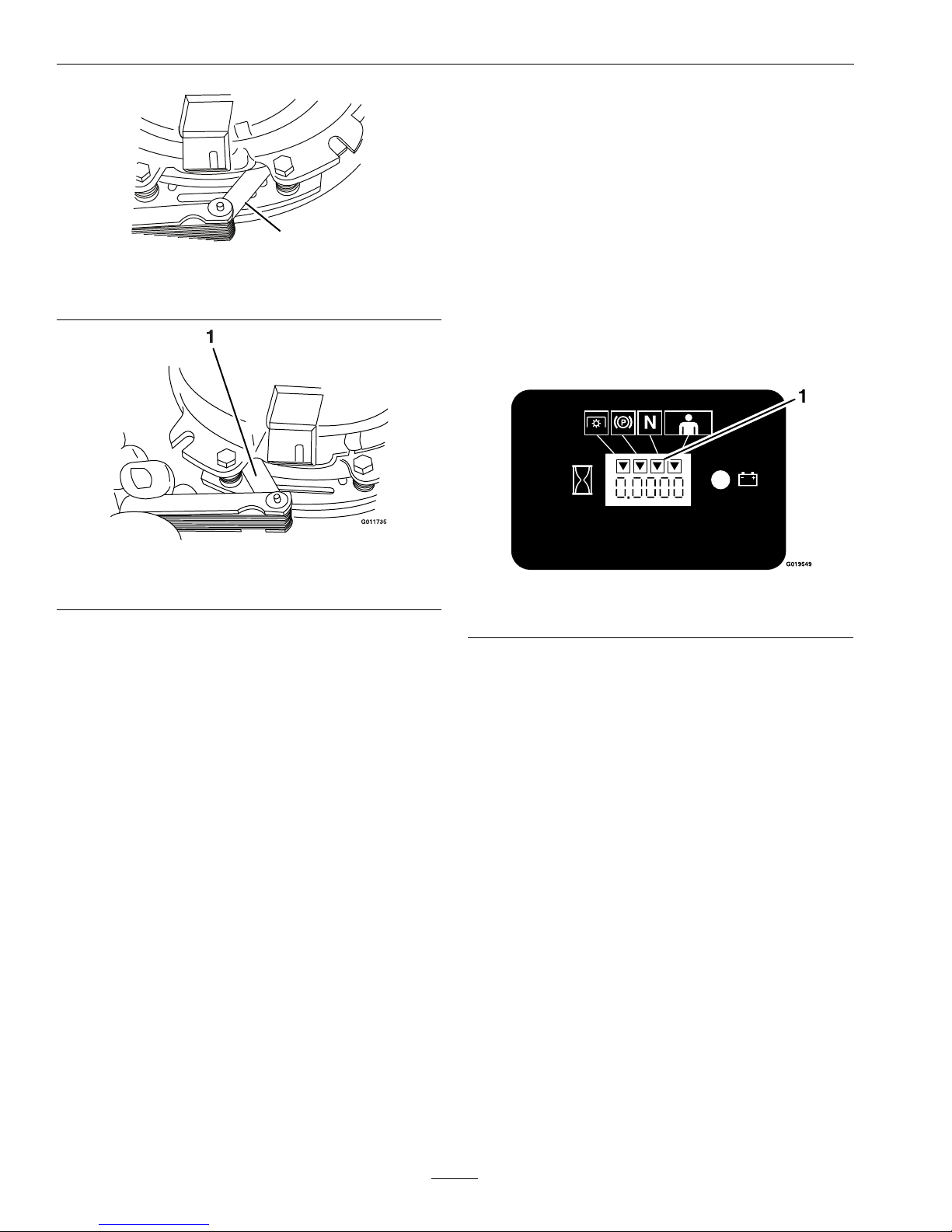
Maintenance
G011733
1
Figure31
1.Feelergauge
Figure32
1.Feelergauge
•Ifthegapislessthan0.010inch,then
reinstalltheshimandreferencethe
Troubleshootingsection.
•Ifthegapissufcient,proceedtothe
safetycheckinstepF.
F.Performthefollowingsafetycheck:
a.Sitontheseatandstarttheengine.
b.MakesurethebladesDoNotengagewith
thePTOswitch“off”andtheclutch
disengaged.
Iftheclutchdoesnotdisengage,
reinstalltheshimandreferencethe
Troubleshootingsection.
c.EngageanddisengagethePTOswitch
tenconsecutivetimestoensuretheclutch
isfunctioningproperly .Iftheclutch
doesnotengageproperly,referencethe
Troubleshootingsection.
NeutralAdjustment
IfthemachinetravelsortheLCDindicatorlight
doesnotilluminatewhenthespeedcontrolleverisin
neutral,thenanadjustmentisrequired.
1.Stopengineandwaitforallmovingpartsto
stop.Engageparkingbrake.Raisetherearofthe
machineupontojackstandshighenoughtoraise
thedrivewheelsoffoftheground.
2.Releasetherearcushionfromtherearofthe
machine.
A.Checkthespeedcontrollinkageand
neutralsafetyswitch:
a.Withtheengineoff,turntheignition
switchtothe“ON”position.
b.LocatetheLCDindicatorinthemessage
display.
Figure33
1.NeutralLCDindicator
c.Withthespeedcontrolleverintheneutral
position,theneutralLCDindicatorshould
appear.
d.Iftheindicatorilluminates,pushthelever
ahead;theindicatorshoulddisappear
within3/4inch(19mm)amountoftravel.
Ifitexceedsthisdistance,anadjustment
totheneutralswitchisrequired.
e.Iftheindicatordoesnotilluminate,with
thespeedcontrolleverinthefullback
position,anadjustmenttotheneutral
switchisrequired.
f.Pullthespeedcontrolleverbackto
neutral.Checkthattheneutralsafety
switchactuatingtabhasdepressedthe
plungeroftheswitchsothatthereisabout
11/32inch(8.6mm)betweenthetaband
theswitch(seeFigure34).Ifnecessary,
movetheswitchforeandaft.
42
Page 43

Maintenance
Figure34
1.11/32inch(8.6mm)
B.DriveWheelsAdjustment:
WARNING
Enginemustberunninganddrivewheels
maybeturningwhenadjustmentis
performed.Contactwithmovingpartsor
hotsurfacesmaycausepersonalinjury.
Keepngers,hands,andclothingclearof
rotatingcomponentsandhotsurfaces.
a.Starttheengineandreleasetheparking
brake.
b.Withthedriveleverrampssetand
tightened(seeAdjusttheNeutralRamp
section),placethedriveleversinthe
neutrallockposition.
c.MoveeitherOPClevertotheoperating
position.
Note:AtleastoneoftheOPClevers
mustbehelddownandtheparkbrake
mustbedisengagedwheneverthespeed
controlleverismovedoutofneutralor
theenginewillkill.
d.Pushthespeedcontrollevertothefull
forwardposition.
e.AdjustthelengthoftheLHandRH
steeringrodsuntilthewheelsarenot
turning.
Figure35
1.LHdrivelever
2.Steeringrod
f.Movethedriveleverstothefullforward
andreverseandthenbacktoneutralto
makesurewheelsarenotturning.Check
withtheneutrallocklatchesengaged.
g.Tightentherodhardware.
Important:Rodsmustbefreetopivot
onrodendballsafteradjustment.
C.SpeedControlLeverAdjustment:
a.Stopengineandwaitforallmovingparts
tostop.
b.Placethedriveleversintheneutrallock
position.
c.Loosentheupperandlowernutsonthe
speedcontrolrod(seeFigure36).
43
Page 44

Maintenance
Figure36
1.Speedcontrollever4.Stud
2.Nut5.Trackingknob
3.Speedcontrolrod
6.Trackingrod
d.Pullthespeedcontrolleverintothefull
back(neutral)position.
e.Allowthespeedcontrolrodtositonthe
stud.
f.Adjustandtightenthenuts.
Note:Makesuretheatoftherodis
perpendiculartothestud.
g.Adjustthetrackingrodbyturningtracking
knobuntiltherodissittingonthestud
(referenceFigure36).
h.Starttheengineandreleasetheparking
brake.
i.MoveeitherOPClevertotheoperating
position.
j.Movethespeedcontrollevertothefull
forwardandthenbacktoneutraltomake
surewheelsarenotturning.Checkwith
theneutrallocklatchesengagedand
disengaged.
k.Checkthetrackingandadjustasneeded
(seeTrackingAdjustmentsection).
D.NeutralRampAdjustment:
Note:Thisadjustmentshouldonlybeneeded
ifcomponentshavebeenreplacedorifneutral
lockandneutraldetentarenotaligned.Adjust
thespeedcontrolleveranddrivewheels
beforeperformingthisadjustment.
a.Stopengineandwaitforallmovingparts
tostop.
b.Placethespeedcontrolleverintothefull
back(neutral)position.
c.Removethesteeringrodfromtheramp
arm.
d.Placethedriveleversintheneutrallock
position(seeFigure8).
e.Rotatetheramparmintoapositionwhere
therampcontactstheroller.Notethis
position.
f.Loosentherampretainingboltandslide
therampuntilbothforwardandreverse
rampsurfacescontacttheroller.Tighten
theramphardware.
Figure37
1.LHdrivelever3.Roller
2.Driveleverrampsurface4.Steeringrod
g.Makethisadjustmentonbothsides.
h.Checktheneutrallocationbymovingthe
driveleversfromforwardtoneutral.Stop
whenachangeinforceintothedetentis
felt.Thethumblocklevershouldeasily
engagewithlittlesteeringmovement;there
shouldnotbeagapbetweenthelocklatch
andthedrivelever.
44
Page 45
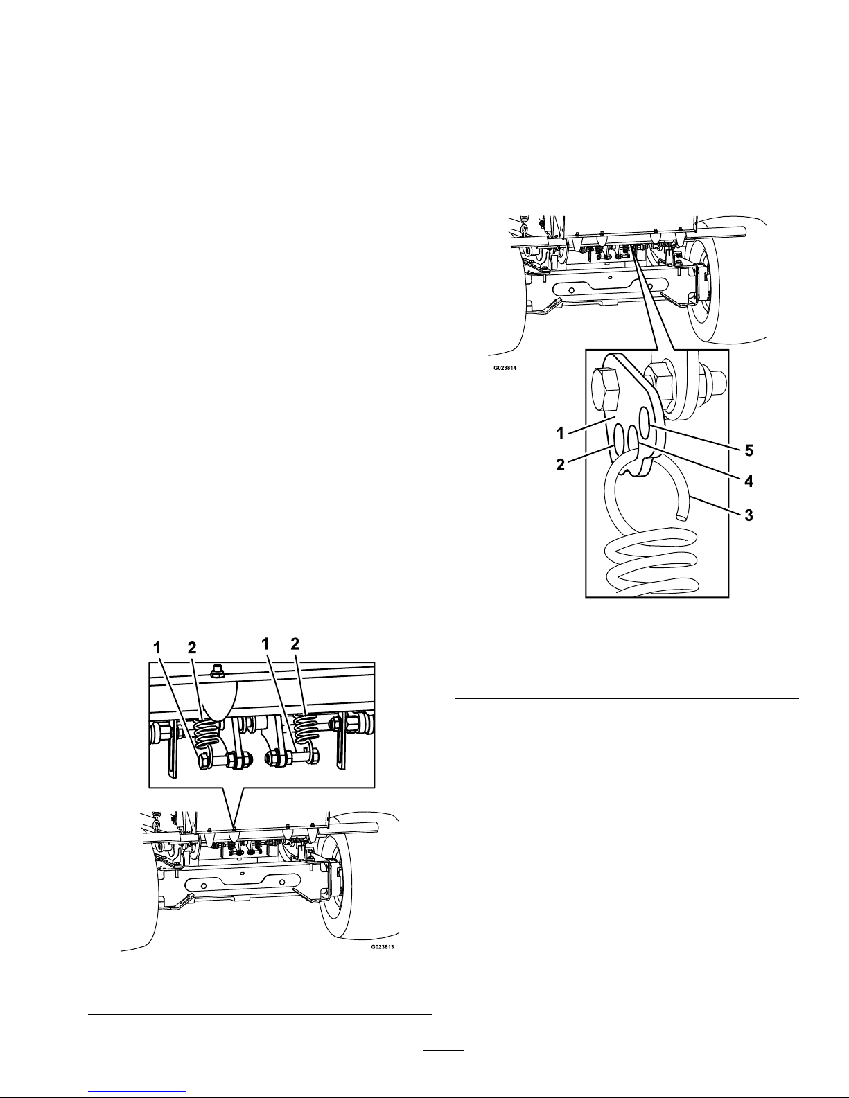
Maintenance
Important:Afterallneutraladjustmentshave
beenmade,makesurethedrivewheelshave
equalspeedinthefullforwardandreverse
positions.
TrackingAdjustment
1.Stopengineandwaitforallmovingpartstostop.
2.Checkthedrivetirepressuresandtire
circumferencesasstatedinChecktheTire
PressuressectioninMaintenance.
3.Runtheunitandobservethetrackingonalevel,
smooth,hardsurfacesuchasconcreteorasphalt.
4.Iftheunittrackstoonesideortheother,turnthe
quicktrackknob.Turntheknobrightto“steer”
right,turntheknobleftto“steer”left.
DriveLeverResistance
Adjustment
Relocatingthehydropumpspringstoadifferent
settingwillchangetheresistanceonthedrivelevers.
1.Stopengine,waitforallmovingpartstostop,and
removekey.Engageparkingbrake.
2.Raisetheplatform.
3.Unhookbothspringsfromthelowerbellcrank
bolts(seeFigure38).
Figure38
1.Lowerbellcrankbolt
2.Spring
4.Lowertheplatform.
5.Releasetherearcushionfromtherearofthe
machineandlowertotheplatform.
6.Relocatetheupperspringhooktothepreferred
resistancesettingontheupperadjustablelink;
refertoFigure39forsettings.
Figure39
1.RHupperadjustablelink4.Recommendedsetting
2.Higherresistance5.Lowerresistance
3.Upperspringhook
7.Reinstalltherearcushionandraisetheplatform.
8.Reinstallthespringlowerhookontothelower
mountingbolts(referenceFigure38).
9.Lowertheplatform.
10.Starttheengine,releasetheparkingbrake,and
drivethemachine.Iftheunitisslowtorespond
ordoesnotperformonhillsasdesired,relocate
theupperspringhooktoadifferentsetting
(referenceFigure39).
Forheavydutydriveconditions,suchasoperation
onsteepslopes,ahigherspringforcemaybe
requiredtopreventthedrivesystemfromstalling.
Locatetheupperspringhookontothebolt.
Note:Inheavydutyposition,thedrivelever
resistancewillalsobeincreased.
45
Page 46

Maintenance
CasterPivotBearings
Pre-LoadAdjustment
Removedustcapfromcasterandtightennylocnut
untilwashersareatandbackoff1/4ofaturn
toproperlysetthepre-loadonthebearings.If
disassembled,makesurethespringdiscwashersare
reinstalledasshowninFigure40.
Figure40
1.Springdiscwashers
Cleaning
CleanEngineandExhaust
SystemArea
ServiceInterval:Beforeeachuseordaily
(Mayberequiredmore
oftenindryordirty
conditions.)
CAUTION
Excessivedebrisaroundenginecoolingair
intakeandexhaustsystemareacancauseengine,
exhaustarea,andhydraulicsystemtooverheat
whichcancreatearehazard.
Cleanalldebrisfromengineandexhaustsystem
area.
1.Stopengine,waitforallmovingpartstostop,and
removekey.Engageparkingbrake.
2.Cleanalldebrisfromrotatingengineairintake
screen,aroundengineshrouding,andexhaust
systemarea.
3.Wipeupanyexcessivegreaseoroilaroundthe
engineandexhaustsystemarea.
4.Cleanoilcoolers(ifequipped)ofalldebris,dirt,
andoil.
RemoveEngineShroudsand
CleanCoolingFins
ServiceInterval:Every80hours
1.Stopengine,waitforallmovingpartstostop,and
removekey.Engageparkingbrake.
2.Removecoolingshroudsfromengineandclean
coolingns.Alsocleandust,dirt,andoilfrom
externalsurfacesofenginewhichcancause
impropercooling.
3.Makesurecoolingshroudsareproperlyreinstalled.
Operatingtheenginewithoutcoolingshroudswill
causeenginedamageduetooverheating.
CleanDebrisFromMachine
ServiceInterval:Beforeeachuseordaily
46
Page 47

Maintenance
1.Stopengine,waitforallmovingpartstostop,and
removekey.Engageparkingbrake.
2.Cleanoffanyoil,debris,orgrassbuild-uponthe
machineandcuttingdeck,especiallyunderdeck
beltshields,aroundthefueltank,aroundengine
andexhaustarea.
CleanGrassBuild-UpUnder
Deck
ServiceInterval:Beforeeachuseordaily
1.Stopengine,waitforallmovingpartstostop,and
removekey.Engageparkingbrake.
2.Raisedecktothetransport(maximumcutting
height)position.Liftthefrontofunitandsupport
unitusingjackstandsorequivalentsupport.
CAUTION
Raisingthemowerforserviceormaintenance
relyingsolelyonmechanicalorhydraulic
jackscouldbedangerous.Themechanicalor
hydraulicjacksmaynotbeenoughsupport
ormaymalfunctionallowingtheunittofall,
whichcouldcauseinjury.
DoNotrelysolelyonmechanicalorhydraulic
jacksforsupport.Useadequatejackstands
orequivalentsupport.
3.Cleanoutanygrassbuild-upfromundersideof
deckandindischargedeector.
WasteDisposal
MotorOilDisposal
Engineoilandhydraulicoilarebothpollutantsto
theenvironment.Disposeofusedoilatacertied
recyclingcenteroraccordingtoyourstateandlocal
regulations.
BatteryDisposal
DANGER
Batteryelectrolytecontainssulfuricacid,which
ispoisonousandcancausesevereburns.
Swallowingelectrolytecanbefatalorifittouches
skincancausesevereburns.
•Wearsafetyglassestoshieldeyes,andrubber
glovestoprotectskinandclothingwhen
handlingelectrolyte.
•DoNotswallowelectrolyte.
•Intheeventofanaccident,ushwithwater
andcalladoctorimmediately .
Federallawstatesthatbatteriesshouldnotbeplaced
inthegarbage.Managementanddisposalpractices
mustbewithinrelevantfederal,state,orlocallaws.
Ifabatteryisbeingreplacedoriftheunitcontaining
thebatteryisnolongeroperatingandisbeing
scrapped,takethebatterytoalocalcertiedrecycling
center.Ifnolocalrecyclingisavailablereturnthe
batterytoanycertiedbatteryreseller.
47
Page 48

Troubleshooting
Troubleshooting
Important:Itisessentialthatalloperatorsafetymechanismsbeconnectedandinproperoperating
conditionpriortomoweruse.
Whenaproblemoccurs,donotoverlookthesimplecauses.Forexample:startingproblemscouldbecaused
byanemptyfueltank.
Thefollowingtablelistssomeofthecommoncausesoftrouble.DoNotattempttoserviceorreplacemajor
itemsoranyitemsthatcallforspecialtimingofadjustmentsprocedures(suchasvalves,governor,etc.).Have
thisworkdonebyyourEngineServiceDealer.
Note:WhendisconnectingelectricalconnectorsDoNotpullonthewirestoseparatetheconnectors.
ProblemPossibleCauseCorrectiveAction
1.PTOisengaged.
1.DisengagethePTO .
2.Speedcontrolleverisnotinneutrallock
position.
2.Ensurethespeedcontrolleverisinthe
neutrallockposition.
3.OPCleversarereleased.
3.DepressOPClevers.
4.Batterydoesnothaveafullcharge.
4.
Chargethebattery.SeeCheckBattery
ChargeandRecommendedJump
StartingProceduresectionsin
Maintenance.
5.Electricalconnectionsarecorroded,loose
orfaulty.
5.Checktheelectricalconnectionsfor
goodcontact.Cleanconnectorterminals
thoroughlywithelectricalcontactcleaner,
applydielectricgreaseandreconnect.
6.Fuseisblown.6.Replacetheblownfuse.
7.NeutralLCDindicatordoesnot
illuminate.
7.Checkneutralswitch.
Starterdoesnotcrank.
8.Relayorswitchisdefective.8.ContactanAuthorizedServiceDealer.
1.Fueltankisempty .1.Fillthefueltank.
2.Fuelshutoffvalveisclosed.
2.Openthefuelshutoffvalve.
3.Thethrottleandchokearenotinthe
correctposition.
3.Besurethethrottlecontrolismidway
betweenthe“SLOW”and“FAST”
positions,andthechokeisinthe“ON”
positionforacoldengineorthe“OFF”
positionforawarmengine.
4.Dirtinfuellter.4.Replacethefuellter.
5.Dirt,water,orstalefuelisinthefuel
system.
5.ContactanAuthorizedServiceDealer.
6.Aircleanerisdirty.
6.Cleanorreplacetheaircleanerelement.
7.Electricalconnectionsarecorroded,loose
orfaulty.
7.Checktheelectricalconnectionsfor
goodcontact.Cleanconnectorterminals
thoroughlywithelectricalcontactcleaner,
applydielectricgreaseandreconnect.
8.Relayorswitchisdefective.8.ContactanAuthorizedServiceDealer.
9.Faultysparkplug.
9.Clean,adjustorreplacesparkplug.
10.Sparkplugwireisnotconnected.
10.Checkthesparkplugwireconnection.
Enginewillnotstart,startshard,orfailsto
keeprunning
11.MILilluminatesandblinks11.ContactanAuthorizedServiceDealer.
48
Page 49

Troubleshooting
ProblemPossibleCauseCorrectiveAction
1.Engineloadisexcessive1.Reducethegroundspeed.
2.Aircleanerisdirty.
2.Cleanorreplacetheaircleanerelement.
3.Oillevelinthecrankcaseislow .
3.Addoiltothecrankcase.
4.Coolingnsandairpassagesforthe
engineareplugged.
4.Removetheobstructionsfromthe
coolingnsandairpassages.
5.Ventholeinthefuelcapisplugged.
5.Cleanorreplacethefuelcap.
6.Dirtinfuellter.6.Replacethefuellter.
Enginelosespower
7.Dirt,water,orstalefuelisinthefuel
system.
7.ContactanAuthorizedServiceDealer.
1.Engineloadisexcessive1.Reducethegroundspeed.
2.Oillevelinthecrankcaseislow .
2.Addoiltothecrankcase.
Engineoverheats
3.Coolingnsandairpassagesforthe
engineareplugged.
3.Removetheobstructionsfromthe
coolingnsandairpassages.
1.Tirepressureindrivetiresnotcorrect.1.Adjusttirepressureinthedrivetires.
Mowerpullsleftorright(withleversfully
forward).
2.Trackingneedsadjustment.2.Adjustthetrackingbyturningknob
ontherighthydrocontrollinkagein
thedirectionthatthemowerneedsto
beadjustedto.Turntheknobin1/8
turnincrementsuntilthemowertracks
correctly.
1.Bypassvalveisnotclosedtight.1.Tightenthebypassvalve.
2.Driveorpumpbeltisworn,looseor
broken.
2.Changethebelt.
Machinedoesnotdrive.
3.Driveorpumpbeltisoffapulley .3.Changethebelt.
1.Blade(s)notsharp.1.Sharpentheblade(s).
2.Cuttingblade(s)is/arebent.
2.Installnewcuttingblade(s).
3.Mowerdeckisnotlevel.3.Levelmowerdeckfromside-to-sideand
front-to-rear.
4.Undersideofmowerisdirty.4.Cleantheundersideofthemower.
5.Tirepressureindrivetiresnotcorrect.5.Adjusttirepressureinthedrivetires.
6.Bladespindlebent.6.ContactanAuthorizedServiceDealer.
Unevencuttingheight.
7.Tipsofadjacentbladesareatanuneven
cuttingheight.Bladestipsshouldbeeven
within3/16inchwhichisapproximately
onebladethickness.
7.Replaceblades,spindlesand(or)check
fordamagetomowerdeck.
1.Cuttingblade(s)is/arebentorunbalanced.
1.Installnewcuttingblade(s).
2.Blademountingboltisloose.2.Tightentheblademountingbolt.
3.Enginemountingboltsareloose.3.Tightentheenginemountingbolts.
4.Looseenginepulley ,idlerpulley ,orblade
pulley.
4.Tightentheappropriatepulley.
5.Enginepulleyisdamaged.5.ContactanAuthorizedServiceDealer.
6.Bladespindleisbent.6.ContactanAuthorizedServiceDealer.
Abnormalvibration
7.Beltisdamaged.7.Installnewbelt.
49
Page 50

Troubleshooting
ProblemPossibleCauseCorrectiveAction
1.Drivebeltisoffpulley .1.Checkbeltfordamage;replaceif
necessary.Installdrivebeltandcheck
adjustingshaftsandbeltguidesforcorrect
position.
2.Deckbeltisworn,looseorbroken.2.Installnewdeckbelt.
3.Deckbeltisoffpulley .3.Installdeckpulleyandchecktheidler
pulley,idlerarmandspringforcorrect
positionandfunction.
4.Brokenormissingidlerspring.
4.Replacethespring.
5.Damagedelectricclutch.5.ContactanAuthorizedServiceDealer.
Bladesdonotrotate.
6.OPCleversarereleased.
6.DepressOPClevers.
1.Fuseisblown.
1.Replacefuse.Checkcoilresistance,
batterycharge,chargingsystem,and
wiringconnectionsandreplaceif
necessary.
2.Lowvoltagesupplyattheclutch.
2.Checkcoilresistance,batterycharge,
chargingsystem,andwiringconnections
andreplaceifnecessary.
3.Damagedcoil.
3.Replaceclutch.
4.Inadequatecurrentsupply.4.Repairorreplaceclutchleadwireor
electricalsystem.Cleanconnector
contacts.
5.Rotor/armatureairgapistoolarge.
5.Removeshimorreplaceclutch.
Clutchwillnotengage.
6.OPCleversarereleased.
6.DepressOPClevers.
50
Page 51

Schematics
Schematics
ElectricalDiagram–AllUnitsExceptKohlerEFI
51
Page 52

Schematics
ElectricalDiagram–KohlerEFI
52
Page 53

Schematics
ElectricalSchematic–AllUnitsExceptKohlerEFI
53
Page 54

Schematics
ElectricalSchematic–KohlerEFI
54
Page 55

Schematics
HydraulicDiagram
55
Page 56

General Warranty Conditions and Products Covered
Exmark Mfg. Co. Inc. and its affiliate, Exmark Warranty Company,
pursuant to an agreement between them, jointly warrant on the terms and
conditions herein, that we will repair, replace or adjust any
part on these
products and found by us (in the exercise of our reasonable discretion) to
be defective in factory materials or workmanship.
This warranty may only be assigned or transferred to a second (or third)
owner by an authorized Exmark dealer. The warranty period commences
upon the date of the original retail purchase.
Commercial Warranty Conditions
This warranty applies to Exmark Lazer Z X-Series, Lazer Z S-Series, and
Vantage turf equipment sold in the U.S. or Canada for a period of three
years for commercial usage.
This warranty includes the cost of parts and labor for a period of two
years and the cost of parts for one additional year. This warranty does not
cover pickup and delivery charges to and from any authorized Exmark
Service Dealer.
Consumer Warranty Conditions
This warranty applies to Exmark Lazer Z X-Series, Lazer Z S-Series, and
Vantage turf equipment sold in the U.S. or Canada for a period of five
years or 750 hours (whichever occurs first) for residential usage.
Residential usage means use of the product on the same lot as your home.
Use at more than one location is considered commercial use, and the
commercial use warranty detailed above would apply.
This warranty only includes the cost of parts and labor. For the first
warrantable service repair, Exmark will cover up to $45 for associated
pick-up and delivery charges to and from any authorized Exmark Service
Dealer. Additional transportation charges may apply, contact your Dealer
for details.
Warranty Exceptions
Warranty Exceptions Warranty Period
• Bags, Belts and Tires 90 days
• Battery 1 Year Prorated
• Engine *
* The Engine warranty is covered by the engine manufacturer. Please
refer to the engine manufacturer’s warranty statement that is included in
the literature packet.
Items and Conditions Not Covered
This warranty does not cover the following:
• Any damage or deterioration due to normal use, wear and tear, or
exposure.
• Cost of regular maintenance service or parts, such as filters, fuel,
lubricants, tune-up parts, and adjustments.
• Any product or part which has been altered or misused or required
replacement or repair due to normal wear, accidents, or lack of proper
maintenance as set forth in the maintenance section of the operator’s
manual.
• Any repairs necessary due to use of parts, accessories or supplies,
including gasoline, oil or lubricants, incompatible with the turf
equipment or other than as recommended in the operator's manual or
other operational instructions provided by Exmark.
There are no other express warranties except for engine and special
emission system coverage.
All warranty work must be performed by an authorized Exmark Service
Dealer using Exmark approved replacement parts.
Instructions for Obtaining Warranty Service
The product must be registered with original proof of purchase by an
Exmark Service Dealer before obtaining any warranty service.
Contact any Exmark Service Dealer to arrange service at their dealership.
To locate a dealer convenient to you, access our website at
www.exmark.com. U.S. or Canada customers may also call
402-223-6375.
If for any reason you are dissatisfied with the Service Dealer’s analysis or
with the assistance provided, contact us at:
Exmark Customer Service Department
The Exmark Warranty Company
2101 Ashland Avenue
Beatrice, NE 68310
402-223-6375 or
service@exmark.com
Owner’s Responsibilities
If your product requires warranty service it must be returned to an
authorized Exmark service dealer within the warranty period. This
warranty extends only to turf equipment operated under normal
conditions. You must read the operator’s manual. You must also properly
service and maintain your Exmark product as described in the operator’s
manual. Such routine maintenance, whether performed by a dealer or by
you, is at your expense.
General Conditions
The sole liability of Exmark and Exmark Warranty Company with respect
to this warranty shall be repair or replacement of defective components as
set forth herein. Neither Exmark nor Exmark Warranty Company
shall be liable for any incidental or consequential loss or damage.
Such damages include but are not limited to:
• Expenses related to gasoline, oil or lubricants.
• Travel time, overtime, after hours time or other extraordinary repair
charges or charges relating to repairs or replacements outside of
normal business hours at the place of business of the authorized
Exmark Service Dealer.
• Rental of like or similar replacement equipment during the period of
any warranty, repair or replacement work.
• Any telephone or telegram charges or travel charges.
• Loss or damage to person or property other than that covered by the
terms of this warranty.
• Any claims for lost revenue, lost profit or additional cost as
a result of a claim of breach of warranty.
• Attorney's fees.
No Claim of breach of warranty shall be cause for cancellation or
rescission of the contract of sale of any Exmark mower.
All implied warranties of merchantability (that the product is fit for
ordinary use) and fitness for use (that the product is fit for a
particular purpose) are limited to the duration of the express
warranty.
Some states do not allow exclusions of incidental or consequential
damages, or limitations on how long an implied warranty lasts, so the
above exclusions and limitations may not apply to you.
This warranty gives you specific legal rights, and you may also have
other rights which vary from state to state.
Exmark Lazer Z X-Series, Lazer Z S-Series, and Vantage Turf Equipment
3 Year Limited Commercial Warranty
5 Year or 750 Hours Limited Consumer Warranty
G4500-733_C
56
Page 57

ServiceRecord
Date:
DescriptionofWorkDone:ServiceDoneBy:
57
Page 58

58
Page 59

G011841
Figure41
Thispagemaybecopiedforpersonaluse.
1.Themaximumslopeyoucansafelyoperatethemachineonis20degrees.Usetheslopeindicatortodeterminethe
degreeofslopeofhillsbeforeoperating.DoNotoperatethismachineonaslopegreaterthan20degrees.Fold
alongtheappropriatelinetomatchtherecommendedslope.
2.Alignthisedgewithaverticalsurface,atree,building,fencepole,etc.
3.Exampleofhowtocompareslopewithfoldededge.
59
Page 60

MI D-MOUNT RIDING ACCE SSORIES AND OPTIONS
EXMARK ACCESSORIES AND OPTIONS*
WALK-BEHIND ACCESSORIES AND OPTIONS
GRASS CATCHER
MICRO-MULCH SYSTEM
TURF STRIPER
STANDON
CUSTOM RIDE SEAT SUSPENSION SYSTEM
FULL SUSPENSION SEAT
DECK LIFT ASSIST KIT
HITCH KIT
LIGHT KIT
12
V POWER PORT
MICRO-MULCH SYSTEM
OPERATOR CONTROLLED DISCHARGE
SUN SHADE
TRASH CONTAINER
TURF STRIPER
ULTRA VAC COLLECTION SYSTEM
ULTRA VAC QUICK DISPOSAL SYSTEM
OU T- FRON T RIDING ACCESSORIES AND OPTIONS
CUSTOM RIDE SEAT SUSPENSION SYSTEM
DUAL-TAIL WHEEL
FLOOR PAN EXTENDER
HITCH KIT
LIGHT KIT
MICRO-MULCH SYSTEM
ROLL OVER PROTECTION SYSTEM (ROPS)
SNOW BLADE
SNOWBLOWER
SUN SHADE
TRASH CONTAINER
ULTRA VAC COLLECTION SYSTEM
ULTRA VAC QUICK DISPOSAL SYSTEM
WEATHER CAB
*Some accessories and options not available for some models.
PlaceModelNo.andSerialNo.
LabelHere(IncludedintheLiterature
Pack)orFillinBelow
DatePurchased
EngineModelNo.andSpec.No.
ModelNo.EngineSerialNo.(E/No)
SerialNo.
©2014ExmarkMfg.Co.,Inc.
IndustrialParkBox808
Beatrice,NE68310
AllRightsReserved
PartNo.4502-224Rev .A
(402)223-6300
Fax(402)223-5489
PrintedintheUSA
*4502-224*A
www.exmark.com
 Loading...