

Page 1

V ANTAGE™
ForSerialNos.
850,000&Higher
PartNo.4500-648Rev.B
Page 2
WARNING
CALIFORNIA
Proposition65Warning
Theengineexhaustfromthisproduct
containschemicalsknowntotheStateof
Californiatocausecancer,birthdefects,or
otherreproductiveharm.
Important:Theengineinthisproductisnot
equippedwithasparkarrestermufer.Itisa
violationofCaliforniaPublicResourceCode
(CPRC)Section4442touseoroperatethis
engineonanyforest-covered,brush-covered,or
grass-coveredlandasdenedinCPRC4126.
Otherstatesorfederalareasmayhavesimilar
laws.
Toacquireasparkarresterforyourunit,seeyour
EngineServiceDealer.
ThissparkignitionsystemcomplieswithCanadian
ICES-002Cesystèmed’allumageparètincellede
vèhiculeestconformeàlanormeNMB-002du
Canada.
TheenclosedEngineOwner’sManualis
suppliedforinformationregardingTheU.S.
EnvironmentalProtectionAgency(EPA)and
theCaliforniaEmissionControlRegulationof
emissionsystems,maintenanceandwarranty.
KeepthisengineOwner’sManualwithyourunit.
ShouldthisengineOwner’sManualbecome
damagedorillegible,replaceimmediately.
Replacementsmaybeorderedthroughthe
enginemanufacturer.
Exmarkreservestherighttomakechangesor
addimprovementstoitsproductsatanytime
withoutincurringanyobligationtomakesuch
changestoproductsmanufacturedpreviously.
Exmark,oritsdistributorsanddealers,accept
noresponsibilityforvariationswhichmaybe
evidentintheactualspecicationsofitsproducts
andthestatementsanddescriptionscontained
inthispublication.
©2010—ExmarkMfg.Co.,Inc.
IndustrialParkBox808
Beatrice,NE68310
2
Contactusatwww.Exmark.com.
PrintedintheUSA
AllRightsReserved
Page 3
Introduction
CONGRATULATIONSonthepurchaseofyour
ExmarkMower.Thisproducthasbeencarefully
designedandmanufacturedtogiveyouamaximum
amountofdependabilityandyearsoftrouble-free
operation.
Thismanualcontainsoperating,maintenance,
adjustment,andsafetyinstructionsforyourExmark
mower.
BEFOREOPERATINGYOURMOWER,
CAREFULLYREADTHISMANUALINITS
ENTIRETY.
Byfollowingtheoperating,maintenance,andsafety
instructions,youwillprolongthelifeofyourmower,
maintainitsmaximumefciency ,andpromotesafe
operation.
Ifadditionalinformationisneeded,orshouldyou
requiretrainedmechanicservice,contactyour
authorizedExmarkequipmentdealerordistributor.
Exmarkpartsmanualsareavailableonlineat
http://www.exmark.com/manuals.htm.
AllExmarkequipmentdealersanddistributorsare
keptinformedofthelatestmethodsofservicing
andareequippedtoprovidepromptandefcient
serviceintheeldorattheirservicestations.They
carryamplestockofservicepartsorcansecurethem
promptlyforyoufromthefactory.
AllExmarkpartsarethoroughlytestedandinspected
beforeleavingthefactory,however,attentionis
requiredonyourpartifyouaretoobtainthefullest
measureofsatisfactionandperformance.
Wheneveryouneedservice,genuineExmarkparts,
oradditionalinformation,contactanAuthorized
ServiceDealerorExmarkCustomerServiceandhave
themodelandserialnumbersofyourproductready.
Figure1identiesthelocationofthemodelandserial
numbersontheproduct.Writethenumbersinthe
spaceprovided.
Figure1
1.Modelandserialnumberlocation
ModelNo.
SerialNo.
3
Page 4

Contents
Introduction...........................................................3
Safety.....................................................................5
SafetyAlertSymbol.........................................5
SafeOperatingPractices..................................5
SafetyandInstructionalDecals.....................10
Specications.......................................................13
ModelNumbers............................................13
Systems.........................................................13
Dimensions...................................................14
TorqueRequirements....................................15
ProductOverview................................................15
Operation.............................................................16
Controls........................................................16
Pre-Start........................................................18
OperatingInstructions..................................18
Transporting.................................................23
Maintenance.........................................................25
RecommendedMaintenanceSchedule(s)...........25
PeriodicMaintenance.......................................26
CheckEngineOilLevel.................................26
CheckBatteryCharge....................................26
CheckMowerBlades.....................................28
CheckSafetyInterlockSystem.......................29
CheckforLooseHardware............................30
ServiceAirCleaner........................................30
ChangeEngineOil........................................30
CheckHydraulicOilLevel.............................30
CheckTirePressures.....................................31
CheckConditionOfBelts..............................31
LubricateGreaseFittings...............................31
LubricateCasterWheelHubs........................31
CheckSparkPlugs.........................................32
ChangeHydraulicSystemFilterand
Fluid.........................................................32
WheelHub-SlottedNutTorque
Specication..............................................34
CheckSparkArrester(ifequipped).................34
ThreadLockingAdhesives.............................34
MobilHTSGrease(OrFood-Grade
Anti-seize).................................................34
Copper-BasedAnti-seize...............................35
DielectricGrease...........................................35
Adjustments.....................................................35
DeckLeveling...............................................35
AdjustingtheCuttingDeckRake...................36
AdjustingtheRearoftheDeck.......................37
PumpDriveBeltTension...............................37
MowerDeckDriveBeltTension....................37
ChecktheParkBrake.....................................37
ParkBrakeAdjustment..................................37
ElectricClutchAdjustment............................38
MotionControlNeutralAdjustment..............39
MotionControlTrackingAdjustment............40
AdjustRHMotionControlHandle
Position.....................................................40
CasterPivotBearingsPre-Load
Adjustment...............................................41
Cleaning...........................................................42
CleanEngineandExhaustSystem
Area..........................................................42
RemoveEngineShroudsandCleanCooling
Fins...........................................................42
CleanDebrisFromMachine..........................42
CleanGrassBuild-UpUnderDeck................42
WasteDisposal..............................................42
Troubleshooting...................................................44
Schematics...........................................................46
4
Page 5

Safety
Safety
SafetyAlertSymbol
ThisSafetyAlertSymbol(Figure2)isusedbothin
thismanualandonthemachinetoidentifyimportant
safetymessageswhichmustbefollowedtoavoid
accidents.
Thissymbolmeans:ATTENTION!BECOME
ALERT!YOURSAFETYISINVOLVED!
Figure2
1.Safetyalertsymbol
Thesafetyalertsymbolappearsaboveinformation
whichalertsyoutounsafeactionsorsituations
andwillbefollowedbythewordDANGER,
WARNING,orCAUTION.
DANGER:Whitelettering/Redbackground.
Indicatesanimminentlyhazardoussituationwhich,if
notavoided,Willresultindeathorseriousinjury.
WARNING:Blacklettering/Orangebackground.
Indicatesapotentiallyhazardoussituationwhich,if
notavoided,Couldresultindeathorseriousinjury.
CAUTION:Blacklettering/Yellowbackground.
Indicatesapotentiallyhazardoussituationwhich,if
notavoided,Mayresultinminorormoderateinjury.
Thismanualusestwootherwordstohighlight
information.Importantcallsattentiontospecial
mechanicalinformationandNoteemphasizes
generalinformationworthyofspecialattention.
SafeOperatingPractices
Training
•ReadtheOperator’sManualandothertraining
material.Iftheoperator(s)ormechanic(s)can
notreadEnglishitistheowner’sresponsibilityto
explainthismaterialtothem.
•Becomefamiliarwiththesafeoperationofthe
equipment,operatorcontrols,andsafetysigns.
•Alloperatorsandmechanicsshouldbetrained.
Theownerisresponsiblefortrainingtheusers.
•Neverletchildrenoruntrainedpeopleoperate
orservicetheequipment.Localregulationsmay
restricttheageoftheoperator.
•Onlyadultsandmatureteenagersshouldoperate
amower,andevenmatureteenagersshouldhave
adultsupervision.Besureateenager:
1.hasreadandunderstandstheOperator’s
Manualandrecognizestherisksinvolved;
2.issufcientlymaturetousecaution;and
3.isofsufcientsizeandweighttooperate
thecontrolscomfortablyandtomanagethe
mowerwithouttakingrisks.
•Theowner/usercanpreventandisresponsible
foraccidentsorinjuriesoccurringtohimselfor
herself,otherpeopleorproperty.
Preparation
•Evaluatetheterraintodeterminewhataccessories
andattachmentsareneededtoproperlyand
safelyperformthejob.Onlyuseaccessoriesand
attachmentsapprovedbyExmark.
•Wearappropriateclothingincludingsafetyglasses,
substantialfootwear,longtrousers,andhearing
protection.DoNotoperatewhenbarefootor
whenwearingopensandals.Longhair,loose
clothingorjewelrymaygettangledinmoving
parts.
CAUTION
Thismachineproducessoundlevelsin
excessof85dBAattheoperator’searand
cancausehearinglossthroughextended
periodsofexposure.
Wearhearingprotectionwhenoperatingthis
machine.
•Inspecttheareawheretheequipmentistobe
usedandremoveallrocks,toys,sticks,wires,
bones,andotherforeignobjectswhichcanbe
thrownbythemachineandmaycausepersonal
injurytotheoperatororbystanders.
5
Page 6

Safety
DANGER
Incertainconditionsgasolineisextremely
ammableandvaporsareexplosive.
Areorexplosionfromgasolinecanburn
you,others,andcausepropertydamage.
•Fillthefueltankoutdoorsonlevel
ground,inanopenarea,whentheengine
iscold.Wipeupanygasolinethatspills.
•Neverrellthefueltankordrainthe
machineindoorsorinsideanenclosed
trailer.
•DoNotllthefueltankcompletelyfull.
Fillthefueltanktothebottomoftheller
neck.Theemptyspaceinthetankallows
gasolinetoexpand.Overllingmayresult
infuelleakageordamagetotheengine
oremissionsystem(ifequipped).
•Neversmokewhenhandlinggasoline,
andstayawayfromanopenameor
wheregasolinefumesmaybeignitedby
spark.
•Storegasolineinanapprovedcontainer
andkeepitoutofthereachofchildren.
•Addfuelbeforestartingtheengine.
Neverremovethecapofthefueltankor
addfuelwhenengineisrunningorwhen
theengineishot.
•Iffuelisspilled,DoNotattempttostart
theengine.Moveawayfromtheareaof
thespillandavoidcreatinganysourceof
ignitionuntilfuelvaporshavedissipated.
•DoNotoperatewithoutentireexhaust
systeminplaceandinproperworking
condition.
DANGER
Incertainconditionsduringfueling,static
electricitycanbereleasedcausingaspark
whichcanignitegasolinevapors.Areor
explosionfromgasolinecanburnyouand
othersandcausepropertydamage.
•Alwaysplacegasolinecontainersonthe
groundawayfromyourvehiclebefore
lling.
•DoNotllgasolinecontainersinsidea
vehicleoronatruckortrailerbedbecause
interiorcarpetsorplastictruckbedliners
mayinsulatethecontainerandslowthe
lossofanystaticcharge.
•Whenpractical,removegas-powered
equipmentfromthetruckortrailerand
refueltheequipmentwithitswheelson
theground.
•Ifthisisnotpossible,thenrefuelsuch
equipmentonatruckortrailerfroma
portablecontainer,ratherthanfroma
gasolinedispensernozzle.
•Ifagasolinedispensernozzlemustbe
used,keepthenozzleincontactwiththe
rimofthefueltankorcontaineropening
atalltimesuntilfuelingiscomplete.
WARNING
Gasolineisharmfulorfatalifswallowed.
Long-termexposuretovaporshascaused
cancerinlaboratoryanimals.Failuretouse
cautionmaycauseseriousinjuryorillness.
•Avoidprolongedbreathingofvapors.
•Keepfaceawayfromnozzleandgas
tank/containeropening.
•Keepawayfromeyesandskin.
•Neversiphonbymouth.
•Checkthattheoperator’spresencecontrols,
safetyswitches,andshieldsareattachedand
functioningproperly.DoNotoperateunlessthey
arefunctioningproperly.
6
Page 7

Safety
Operation
WARNING
Operatingengineparts,especiallythe
mufer,becomeextremelyhot.Severeburns
canoccuroncontactanddebris,suchas
leaves,grass,brush,etc.cancatchre.
•Allowengineparts,especiallythemufer,
tocoolbeforetouching.
•Removeaccumulateddebrisfrommufer
andenginearea.
•Installandmaintaininworkingordera
sparkarresterbeforeusingequipment
onforest-covered,grass-covered,or
brush-coveredunimprovedland.
WARNING
Engineexhaustcontainscarbonmonoxide,
whichisanodorlessdeadlypoisonthatcan
killyou.
DoNotrunengineindoorsorinasmall
connedareawheredangerouscarbon
monoxidefumescancollect.
•Operateonlyindaylightorgoodarticiallight,
keepingawayfromholesandhiddenhazards.
•Besurealldrivesareinneutralandparkingbrake
isengagedbeforestartingengine.
•Neverraisedeckwithbladesrunning.
•Neveroperatethemowerwithdamagedguards,
shields,orcovers.Alwayshavesafetyshields,
guards,switchesandotherdevicesinplaceandin
properworkingcondition.
•Nevermowwiththedischargedeectorraised,
removedoralteredunlessthereisagrass
collectionsystemormulchkitinplaceand
workingproperly .
•DoNotchangetheenginegovernorsettingor
overspeedtheengine.
•Stopengine,waitforallmovingpartstostop,
removekeyandengageparkingbrake:
–Beforechecking,cleaningorworkingonthe
mower.
–Afterstrikingaforeignobjectorabnormal
vibrationoccurs(inspectthemowerfor
damageandmakerepairsbeforerestarting
andoperatingthemower).
–Beforeclearingblockages.
–Wheneveryouleavethemower.
•Stopengine,waitforallmovingpartstostop,and
engageparkingbrake:
–Beforerefueling.
–Beforedumpingthegrasscatcher.
–Beforemakingheightadjustments.
WARNING
Hands,feet,hair,clothing,oraccessoriescan
becomeentangledinrotatingparts.Contact
withtherotatingpartscancausetraumatic
amputationorseverelacerations.
•DoNotoperatethemachinewithout
guards,shields,andsafetydevicesin
placeandworkingproperly.
•Keephands,feet,hair,jewelry,orclothing
awayfromrotatingparts.
•DONOToperatethemowerwhenpeople,
especiallychildren,orpetsareinthearea.
•Bealert,slowdownandusecautionwhenmaking
turns.Lookbehindandtothesidebefore
changingdirections.
•Stoptheblades,slowdown,andusecautionwhen
crossingsurfacesotherthangrassandwhen
transportingthemowertoandfromtheareato
bemowed.
•Beawareofthemowerdischargepathanddirect
dischargeawayfromothers.
•DoNotoperatethemowerundertheinuence
ofalcoholordrugs.
•Useextremecarewhenloadingorunloadingthe
machineintoatrailerortruck.
•Usecarewhenapproachingblindcorners,shrubs,
trees,orotherobjectsthatmayobscurevision.
SlopeOperation
UseExtremecautionwhenmowingand/orturning
onslopesaslossoftractionand/ortip-overcould
occur.Theoperatorisresponsibleforsafeoperation
onslopes.
7
Page 8

Safety
DANGER
Operatingonwetgrassorsteepslopescan
causeslidingandlossofcontrol.Lossof
controland/orlossofoperator’sfooting
couldresultinafallwithanarmorleg
gettingunderthemowerorenginedeck
whichmayresultinseriousinjury,deathor
drowning.
•Mowacrossslopes,neverupanddown.
•DoNotmowslopeswhengrassiswet.
•DoNotmowneardrop-offsornearwater.
•DoNotmowslopesgreaterthan20
degrees.
•Reducespeedanduseextremecaution
onslopes.
•Avoidsuddenturnsorrapidspeed
changes.
•Seeinsidethebackcovertodeterminethe
approximateslopeangleoftheareatobemowed.
•Removeormarkobstaclessuchasrocks,tree
limbs,etc.fromthemowingarea.Tallgrasscan
hideobstacles.
•Watchforditches,holes,rocks,dipsandrisesthat
changetheoperatingangle,asroughterraincould
overturnthemachine.
•Avoidsuddenstartswhenmowinguphillbecause
themowermaytipbackwards.
•Beawarethatoperatingonwetgrass,acrosssteep
slopesordownhillmaycausethemowertolose
traction.Lossoftractiontothedrivewheelsmay
resultinslidingandalossofbrakingandsteering.
•Alwaysavoidsuddenstartingorstoppingona
slope.Iftireslosetraction,disengagetheblades
andproceedslowlyofftheslope.
•Followthemanufacturer’srecommendationsfor
wheelweightsorcounterweightstoimprove
stability.
•Useextremecarewithgrasscatchersor
attachments.Thesecanchangethestabilityofthe
machineandcauselossofcontrol.
MaintenanceandStorage
•Disengagedrives,lowerimplement,setparking
brake,stopengineandremovekeyordisconnect
sparkplugwire.Waitforallmovementtostop
beforeadjusting,cleaningorrepairing.
•Keepengineandengineareafreefrom
accumulationofgrass,leaves,excessivegrease
oroil,andotherdebriswhichcanaccumulate
intheseareas.Thesematerialscanbecome
combustibleandmayresultinare.
•Letenginecoolbeforestoringanddonotstore
nearameoranyenclosedareawhereopenpilot
lightsorheatappliancesarepresent.
•Shutofffuelwhilestoringortransporting.Do
Notstorefuelnearamesordrainindoors.
•Parkmachineonlevelground.Neverallow
untrainedpersonneltoservicemachine.
•Usejackstandstosupportcomponentswhen
required.
•Carefullyreleasepressurefromcomponentswith
storedenergy.
•Disconnectbatteryorremovesparkplugwire
beforemakinganyrepairs.Disconnectthe
negativeterminalrstandthepositivelast.
Reconnectpositiverstandnegativelast.
•Usecarewhencheckingblades.Wraptheblade(s)
orweargloves,andusecautionwhenservicing
them.Onlyreplacedamagedblades.Never
straightenorweldthem.
•Keephandsandfeetawayfrommovingparts.
Ifpossible,donotmakeadjustmentswiththe
enginerunning.
•Chargebatteriesinanopenwellventilatedarea,
awayfromsparkandames.Unplugcharger
beforeconnectingordisconnectingfrombattery.
Wearprotectiveclothinganduseinsulatedtools.
8
Page 9

Safety
DANGER
Chargingorjumpstartingthebatterymay
produceexplosivegases.Batterygasescan
explodecausingseriousinjury.
•Keepsparks,ames,orcigarettesaway
frombattery.
•Ventilatewhenchargingorusingbattery
inanenclosedspace.
•Makesureventingpathofbatteryis
alwaysopenoncebatteryislledwith
acid.
•Alwaysshieldeyesandfacefrombattery.
DANGER
Batteryelectrolytecontainssulfuricacid,
whichispoisonousandcancausesevere
burns.Swallowingelectrolytecanbefatalor
ifittouchesskincancausesevereburns.
•Wearsafetyglassestoshieldeyes,and
rubberglovestoprotectskinandclothing
whenhandlingelectrolyte.
•DoNotswallowelectrolyte.
•Intheeventofanaccident,ushwith
waterandcalladoctorimmediately .
CAUTION
Iftheignitionisinthe“ON”positionthere
ispotentialforsparksandengagement
ofcomponents.Sparkscouldcausean
explosionormovingpartscouldaccidentally
engagecausingpersonalinjury.
Besureignitionswitchisinthe“OFF”
positionbeforechargingthebattery.
•Keepallguards,shieldsandallsafetydevicesin
placeandinsafeworkingcondition.
•Checkallboltsfrequentlytomaintainproper
tightness.
•Frequentlycheckforwornordeteriorating
componentsthatcouldcreateahazard.
WARNING
Removingstandardoriginalequipment
parts,orusingnon-Exmarkreplacement
partsandaccessoriesmayalterthewarranty,
traction,andsafetyofthemachine.Failure
touseoriginalExmarkpartscouldcause
seriousinjuryordeath.
Replaceallpartsincluding,butnotlimitedto
tires,belts,andbladeswithoriginalExmark
parts.
WARNING
Hydraulicuidescapingunderpressure
canpenetrateskinandcauseinjury.Fluid
accidentallyinjectedintotheskinmustbe
surgicallyremovedwithinafewhoursbya
doctorfamiliarwiththisformofinjuryor
gangrenemayresult.
•Makesureallhydraulicuidhoses
andlinesareingoodconditionand
allhydraulicconnectionsandttings
aretightbeforeapplyingpressureto
hydraulicsystem.
•Keepbodyandhandsawayfrompinhole
leaksornozzlesthatejecthighpressure
hydraulicuid.
•Usecardboardorpaper,notyourhands,
tondhydraulicleaks.
•Safelyrelieveallpressureinthehydraulic
systembyplacingthemotioncontrol
leversinneutralandshuttingoffthe
enginebeforeperforminganyworkon
thehydraulicsystem.
9
Page 10
Safety
SafetyandInstructionalDecals
•Keepallsafetysignslegible.Removeallgrease,
dirtanddebrisfromsafetysignsandinstructional
labels.
•Replaceallworn,damaged,ormissingsafety
signs.
•Whenreplacementcomponentsareinstalled,be
surethatcurrentsafetysignsareafxedtothe
replacedcomponents.
•Ifanattachmentoraccessoryhasbeeninstalled,
makesurecurrentsafetysignsarevisible.
•Newsafetysignsmaybeobtainedfrom
yourauthorizedExmarkequipmentdealeror
distributororfromExmarkMfg.Co.Inc.
•Safetysignsmaybeafxedbypeelingoffthe
backingtoexposetheadhesivesurface.Apply
onlytoaclean,drysurface.Smoothtoremove
anyairbubbles.
•Familiarizeyourselfwiththefollowingsafetysigns
andinstructionlabels.Theyarecriticaltothesafe
operationofyourExmarkcommercialmower.
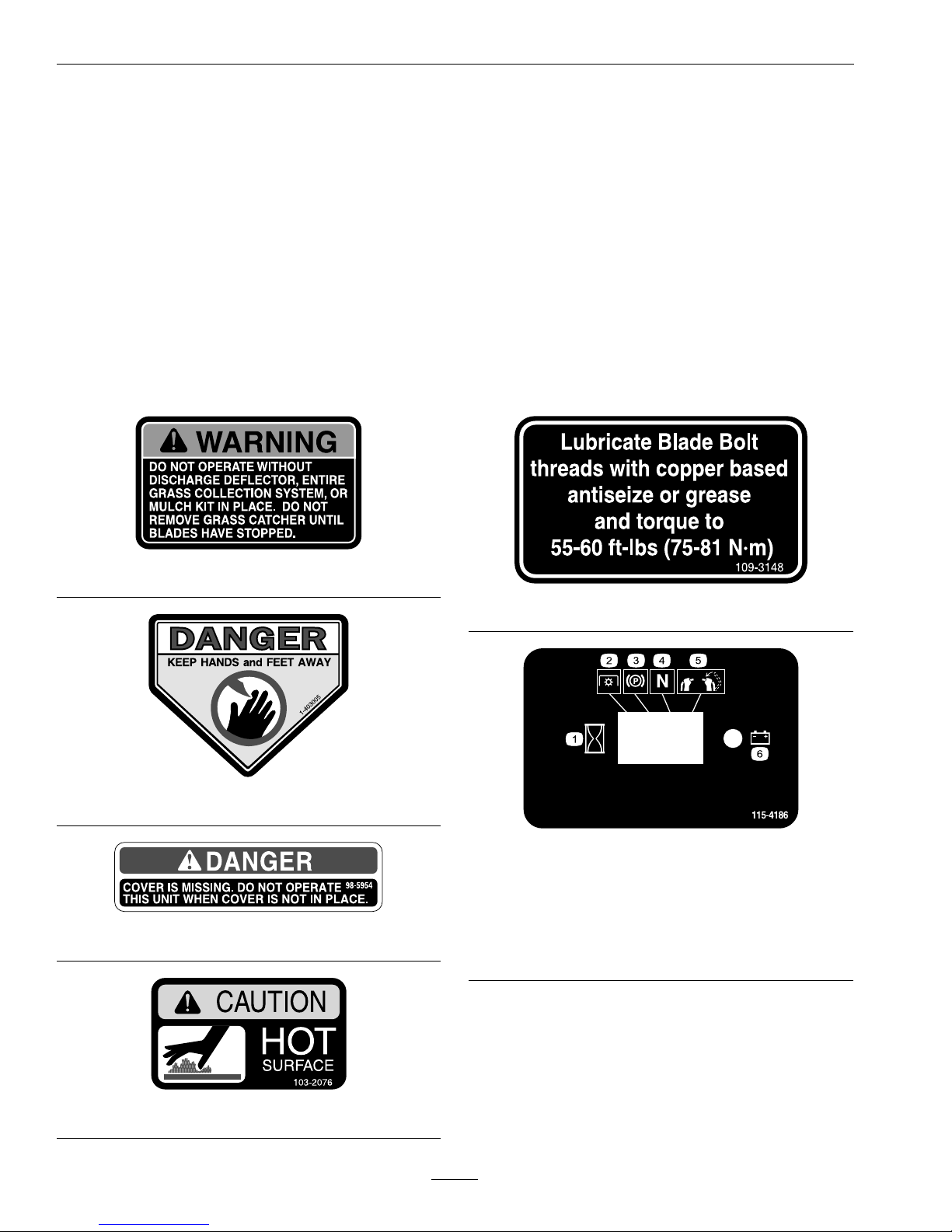
1-303508
1-403005
98-5954
103-2076
109-3148
115-4186
1.Interval
2.PowerTake-off(PTO)
3.Parkingbrake
4.Neutral
5.Operatorpresenceswitch
6.Battery
10
Page 11
Safety
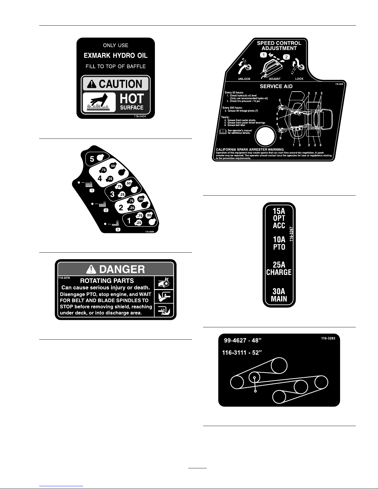
116-0404
116-2040
116-3076
116-3260
1.Forwardposition-faster
2.Backwardposition-slower
116-3267
116-3283
11
Page 12

Safety
116-3290
116-1886
116-1887
1.Fast3.Neutral
2.Slow
4.Reverse
116-3067
1.PTO-on4.Slow
2.PTO-off5.Choke-on
3.Fast
6.Choke-off
12
Page 13

Specications
Specications
ModelNumbers
SerialNos:850,000andHigher
VT20KAS484;VT20KAS524;VT24KAS484;VT24KAS524
Systems
Engine
•EngineSpecications:SeeyourEngineOwner’s
Manual
•RPM:FullSpeed:3600±100RPM(NoLoad)
FuelSystem
•Capacity:8.0gal.(30.2L)
•TypeofFuel:Regularunleadedgasoline,87
octaneorhigher;containingnomorethan10%
methanolorethanol.
•FuelFilter:ReplaceableIn-line
•FuelShut-OffValve:1/4turnincrements
ElectricalSystem(ElectricStart)
•ChargingSystem:FlywheelAlternator
•ChargingCapacity:15amps
•BatteryType:BCIGroupU1
•BatteryVoltage:12Volt
•Polarity:NegativeGround
•Fuses:
–30ampmainfuse
–25ampchargingsystemfuse
–10ampPTOfuse
–15ampaccessoryfuse
SafetyInterlockSystem
•LCDindicatorsappearfortheparkbrake,drive
levers,andoperatorpresenceinthemessage
displayonthefrontcontrolpanel.
Note:BecausethePTOmustbedisengaged
tostarttheengine,theLCDindicatorwillnot
illuminateatthistime.
•PTOmustbedisengaged,brakeengaged,and
motioncontrolleversinneutraltostartengine.
(Itisnotnecessaryfortheoperatortobeonthe
platformtostarttheengine.)
•Mowerbladeswillstopiftherightsidemotion
controlleverismovedorreleasedintoneutral
lockposition.
•Enginewillstopifthemotioncontrolleversare
movedfromtheneutralpositionwiththepark
brakeengaged.
OperatorControls
SteeringControl:Fingertipdrivecontrollevers
provideindependentspeedcontrol,brakingand
neutraltoeachdrivewheelformovingforwardor
reverse,stopping,andpowerturning.
Transmission
•TwoHydroGearvariabledisplacementhigh
efciencypumpsindependentlycoupledtotwo
highefciencyParker/Rosswheeldrivemotors.
•HydraulicOil:UseExmarkPremiumHydroOil.
•HydraulicOilCapacity:2.4qt.(2.2L)
•HydraulicFilterisreplaceablecartridgetype.
P/N109-4180:25microns,10psibypass
(Summeruseabove32°F(0°C))
P/N1-523541:40microns,18psibypass(Winter
usebelow32°F(0°C))
•Speeds:
–0-8.0mph(13km/hr)forward.
–0-4.0mph(6km/hr)reverse.
•Drivewheelsreleasevalvesallowmachinetobe
movedwhenengineisnotrunning.
WheelDriveSystem
DrivewheelsaredirectcoupledtoParkerwheeldrive
motorswith1inch(25.4mm)taperedshaft.
13
Page 14

Specications
Tires&Wheels
DriveFrontCaster
Pneumatic
(Air-Filled)
SemiPneumatic
Quantity
22
Tread
TurfMasterSmooth
Size20x10.00–811x4.00-5
PlyRating
4
Pressure
14psi
(97kPa)
CuttingDeck
•CuttingWidth:
–48inchDeck:48inches(121.9cm)
–52inchDeck:52.00inches(132.1cm)
•Discharge:Side
•BladeSize:(3ea.)
–48inchDeck:16.25inches(41.3cm)
–52inchDeck:18.00inches(45.7cm)
•BladeSpindles:Solidsteelspindleswith1.00inch
(25.4mm)I.D.bearings.
•DeckDrive:
–Electricclutchmountedonengineshaft.
–Bladesdrivenbyonebelt(w/self-tensioning
idlers).
•Deck:Fulloatingdeckisattachedtosupport
frame,removableforservice.Deckdesignallows
forbagging,mulchingorsidedischarge.
•DeckDepth:
–48inchDeck:5.5inches(14.0cm)
–52inchDeck:5.5inches(14.0cm)
•CuttingHeightAdjustment:
Adjustsfrom1inch(2.5cm)to5inches(12.7cm)
in1/4inch(6.4mm)increments
•MulchingKit:Optional
•Bagger:Optional
Dimensions
OverallWidth:
48inchDeck52inchDeck
DeectorUp51.8inches
(131.6cm)
56.3inches
(143.0cm)
DeectorDown59.6inches
(151.4cm)
64.8inches
(164.6cm)
OverallLength:
48inchDeck52inchDeck
PlatformUp59.0inches
(150.0cm)
59.0inches
(150.0cm)
PlatformDown74.0inches
(188.0cm)
74.0inches
(188.0cm)
OverallHeight:
48inchDeck52inchDeck
50.0inches(127.0cm)50.0inches(127.0cm)
TreadWidth:(OutsidetoOutsideof
Tires,Widthwise)
48inchDeck52inchDeck
46.5inches(118.1cm)46.5inches(118.1cm)
CurbWeight:
48inchDeck52inchDeck
855lb(388kg)866lb(393kg)
Note:Weightswillvaryslightlydependingon
engine.
14
Page 15
ProductOverview
TorqueRequirements
BoltLocation
Torque
CutterHousingSpindle
Nut
140-145ft-lb
(190-197N-m)
BladeMountingBolt
(lubricatewithanti-seize)
55-60ft-lb(75-81N-m)
EngineDeck/Mower
DeckSupportMount
Bolts
30-35ft-lb(41-47N-m)
EngineMountingBolts
15-20ft-lb(20-27N-m)
WheelLugNuts
90-95ft-lb(122-129N-m)
WheelHubSlottedNutsminimum100ft-lb
(136N-m)
WheelMotorMounting
Bolts
30-35ft-lb(41-47N-m)
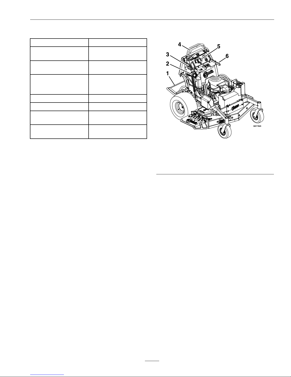
ProductOverview
Figure3
1.Platform
4.Motioncontrollevers
2.FuelCap5.EngineControls
3.Height-of-Cut
Adjustment
6.ParkBrakeLever
15
Page 16
Operation
Operation
Note:Determinetheleftandrightsidesofthe
machinefromthenormaloperatingposition.
Controls
MotionControlLevers
Themotioncontrollevers,locatedoneachsideofthe
topconsole,controltheforwardandreversemotion
ofthemachine.
Movingtheleversforwardorbackwardturns
thewheelonthesamesideforwardorreverse
respectively.Wheelspeedisproportionaltothe
amounttheleverismoved.
Figure4
1.LHMotioncontrollever6.Neutral
2.RHMotioncontrollever7.Forward
3.RHMotioncontrollever
inneutrallockposition
8.Frontreference/Speed
controlbar
4.Reverse
9.Frontofunit
5.Rearreferencebar
Whenthemotioncontrolleversareintheneutral
position,theLCDindicatorappearsinthemessage
displayonthefrontcontrolconsole(seeFigure5
andFigure7).
Whenthemotioncontrolleversareintheneutral
positionandtheRHmotioncontrolleverismoved
intotheneutrallockposition,themowerbladeswill
disengage.
ChokeControl
Locatedonthefrontcontrolconsolerightofthe
PTOengagementswitch.
Thechokeisusedtoaidinstartingacoldengine.
Movingthechokeleverforwardwillputthechokein
the“ON”positionandmovingthechokelevertothe
rear,tothedetent,willputthechokeinthe“OFF”
position.DoNotrunawarmenginewithchokein
the“ON”position.
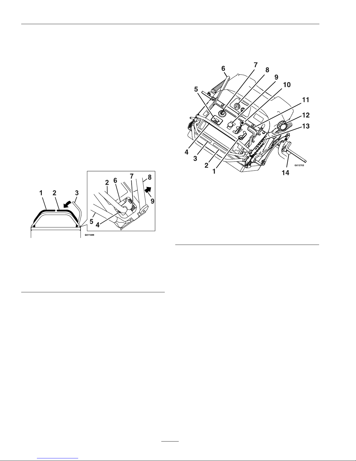
Figure5
1.Throttle8.Fuelgauge
2.RHMotioncontrollever
9.PTOengagementswitch
3.LHMotioncontrollever
10.Choke
4.FrontReference/Speed
ControlBar
11.Decklifthandle
5.Messagedisplay12.Fuelcap
6.Parkbrakelever
13.Height-of-cutpin
7.Ignitionswitch
14.Platformlatch
ThrottleControl
LocatedontheRHsideofthefrontcontrolconsole
(redlever)(seeFigure5).
Thethrottleisusedtocontrolenginespeed.Moving
thethrottleleverforwardwillincreaseenginespeed
andmovingthethrottlelevertotherearwilldecrease
enginespeed.Movingthethrottleforwardintothe
detentisfullthrottle.
FrontReference/SpeedControlBar
Locatedinfrontofthemotioncontrollevers(see
Figure5).
Thefrontreference/speedcontrolbarcontrolsthe
maximumforwardspeedandisinnitelyvariable
fromapproximately4–8mph(6–13km/hr).
ParkBrakeLever
Locatedonleftsideofunit,justtothefrontofthe
LHmotioncontrollever(seeFigure5).
16
Page 17

Operation
Thebrakeleverengagesaparkingbrakeonthedrive
wheels.
Note:TheLCDindicatorappearsinthemessage
displayonthefrontconsolewhentheparkbrakeis
engaged(seeFigure5andFigure7).
Toengagethebrake,pulltheleverrearwardandto
therighttopositionintotheengagedposition.
Torelease,pullthebrakeleverbackandovertothe
left,positionintotheslotandpushtheleverforward.
Whenparkingonasteepslope,thewheelsmustbe
chockedorblockedinadditiontothebrakebeing
engaged.Theunitmustbetieddownandbrake
engagedwhentransporting.
Parkbrakemustbedisengagedbeforemoving
motioncontroloutofneutralorenginewillkill.
IgnitionSwitch
LocatedontheLHsideofthefrontcontrolconsole
(seeFigure5).
Theignitionswitchisusedtostartandstopthe
engine.Theswitchhasthreepositions“OFF”,“ON”
and“START”.Insertkeyintoswitchandrotate
clockwisetothe“ON”position.Rotateclockwiseto
thenextpositiontoengagethestarter(keymustbe
heldagainstspringpressureinthisposition).Allow
thekeytoreturntothe“ON”positionimmediately
aftertheenginestarts.
Figure6
1.Off3.Start
2.On
Note:Brakemustbeengaged,LHmotioncontrol
leverinneutral,theRHmotioncontrolinneutral
lockposition,andPTOswitchdisengagedtostart
engine.(Itisnotnecessaryfortheoperatortobeon
theplatform.)
HourMeter
LocatedontheLHsideofthefrontcontrolconsole
inthemessagedisplay(seeFigure5andFigure7).
Thehourmeterrecordsthenumberofhoursthat
theenginehasrun.
Figure7
1.LCDIndicators
2.Lowvoltageindicatorlight
3.Hour/Voltagedisplay
Thehourmeterisrecordingwhenthedecimalpoint
isashinginHour/Voltagedisplay .
Hoursaredisplayedwhenthekeyisofforwhenthe
machineisrunning.
Note:Iftheignitionkeyisturnedtothe“ON”
positionforafewsecondsbeforecrankingthe
engine,thebatteryvoltagewilldisplayinthearea
wherethehoursarenormallydisplayed.
Note:TheLCDindicatorsappearwheneach
controlmeetsthe“safetostart”mode.Becausethe
PTOmustbedisengagedtostarttheengine,the
LCDindicatorwillnotilluminateatthistime.
FuelShut-OffValve
LocatedontheRHsideofthecontroltowerbehind
thekneecushion.
Thefuelshut-offvalveisusedtoshutoffthefuel
whenthemachinewillnotbeusedforafewdays,
duringtransporttoandfromthejobsite,andwhen
parkedinsideabuilding.
Alignvalvehandlewiththefuellinetoopen.Rotate
90°toclose.
FuelGauge
Locatedonthetopleftsideofthetank(seeFigure5).
17
Page 18

Operation
Thefuelgaugemonitorstheamountoffuelinthe
tank.
DriveWheelReleaseValves
Locatedontheleftrearcornerofthehydrostatic
pumps.
Drivewheelreleasevalvesareusedtoreleasethe
hydrostaticdrivesystemtoallowthemachinetobe
movedbyhandwithouttheenginerunning.
Witha5/8wrench,turnbothvalvesoneturn
counterclockwisetoreleasethedrivesystem.
Turnclockwisetoresetthedrivesystem.DoNot
overtighten.DoNottowmachine.
PTOEngagementSwitch
Locatedonfrontcontrolpanel(seeFigure5).
Switchmustbepulledout(up)toengagetheblades.
Switchispushedintodisengagetheblades.
TheLCDindicatorwillappearwhenthePTOswitch
isengaged(seeFigure7).
LowVoltageIndicator
Locatedonthefrontcontrolpanelinthemessage
display(seeFigure5andFigure7).
Alowvoltagecondition(lessthan12.3volts)exists
whenthelowvoltageindicatorlightappearsonthe
messagedisplaywhiletheengineisrunning.
Iftheignitionkeyisturnedtothe“ON”positionfor
afewsecondsbeforecrankingtheengine,thebattery
voltagewilldisplayintheareawherethehoursare
normallydisplayed.
Note:Theindicatornormallyappearswhenthe
engineisoffandthekeyswitchisturnedtothe
“ON”position.
DeckLiftHandle
LocatedontheRHofthefrontcontrolpanel.
Pullthehandlerearwardtoraisethecuttingdeck.
Allowthehandletomoveforwardtolowerthe
cuttingdecktothecutheightthathasbeenset.
Pullthehandlerearwardandtotherighttolatch
thecuttingdeckintotheraisedtransportposition
(Figure5).
Pre-Start
Fillfueltankonlevelground.Forbestresultsuse
onlyclean,freshregulargradeunleadedgasolinewith
anoctaneratingof87orhigher.
Important:Neverusemethanol,gasoline
containingmethanol,gasoholcontainingmore
than10%ethanol,premiumgasoline,orwhite
gasbecausethefuelsystemcouldbedamaged.
DoNotaddoiltogasoline.
DoNotusegasolinethathasbeenstoredsincethe
lastmowingseasonorlonger.
DoNotoverllfueltank.Fillthefueltanktothe
bottomofthellerneck.Theemptyspaceinthe
tankallowsgasolinetoexpand.Overllingmayresult
infuelleakageordamagetotheengineoremission
system(ifequipped).
Makesureyouunderstandthecontrols,their
locations,theirfunctions,andtheirsafety
requirements.
RefertotheMaintenancesectionandperformallthe
necessaryinspectionandmaintenancesteps.
OperatingInstructions
OpentheFuelShut-OffValve
Rotatethevalveandalignwiththefuellinetoopen.
StartingtheEngine
1.LeavetheLHmotioncontrolleverinneutral
andtheRHleverintheneutrallockposition(see
Figure4).
2.Pulltheparkingbrakerearwardandovertothe
righttoengagetheparkingbrake.
3.Pushin(down)onthePTOswitchtothe
“disengage”position.
4.Placethethrottlemidwaybetweenthe“SLOW”
and“FAST”positions.
5.Onacoldengine,pushthechokeleverforward
intothe“ON”position.
Onawarmengine,leavethechokeinthe“OFF”
position.
6.Turnignitionswitchtothe“START”position.
Releasetheswitchassoonastheenginestarts.
18
Page 19

Operation
Important:DoNotcranktheengine
continuouslyformorethantensecondsata
time.Iftheenginedoesnotstart,allowa60
secondcool-downperiodbetweenstarting
attempts.Failuretofollowtheseguidelines
canburnoutthestartermotor.
7.Ifthechokeisinthe“ON”position,gradually
returnchoketothe“OFF”positionastheengine
warmsup.
PTOEngagement
DANGER
Therotatingbladesunderthemowerdeck
aredangerous.Bladecontactcancause
seriousinjuryorkillyou.
DoNotputhandsorfeetunderthemower
ormowerdeckwhenthebladesareengaged.
DANGER
Anuncovereddischargeopeningwillallow
objectstobethrowninanoperator’sor
bystander’sdirection.Also,contactwiththe
bladecouldoccur.Thrownobjectsorblade
contactcancauseseriousinjuryordeath.
Neveroperatethemowerwiththedischarge
deectorraised,removed,oralteredunless
thereisagrasscollectionsystemormulch
kitinplaceandworkingproperly.
ThePTOswitchengagesthecuttingblades.Besure
allpersonsareclearofmowerdeckanddischarge
areabeforeengagingthePTO.
1.Setthrottleto“MIDWAY”position.
2.Releasetheparkingbrake.
3.Movetherightsidemotioncontrollevertothe
center,operateposition.
4.Continueholdingtherightsidemotioncontrol
leverinthecenter,operatepositionandpullup
onthebladecontrolswitch(PTO)andrelease.
Theclutchshouldengageandthemowerblades
beginrotating.
5.Placethethrottleinthe“FAST”positiontobegin
mowing.
DisengagingthePTO
1.Setthethrottlemidwaybetweenthe“SLOW”
and“FAST”positions.
2.PushdownonthePTOswitchtodisengagethe
blades.
Note:ThePTOwillbedisengagedbyreleasing
therightsidemotioncontrolleverandallowing
ittospringoutwardtotheneutrallockposition.
ThePTOwillnotre-engagewhentheRHmotion
controlleverismovedoutoftheneutrallock
positionwithoutpullinguponthePTOswitch.
TofullydisengagethePTO,continuetopushthe
switchdownward.
StoppingtheEngine
1.Bringtheunittoafullstop.
2.Movethemotioncontrolleverstotheneutral
position;movetheRHcontrolleverouttothe
neutrallockposition.
3.Placethethrottlemidwaybetweenthe“SLOW”
and“FAST”positions.
4.PushdownonthePTOswitchtodisengagethe
blades.
5.Engagetheparkingbrake.
6.Allowtheenginetorunforaminimumof15
seconds,thenturntheignitionswitchtothe
“OFF”positiontostoptheengine.
7.Removethekeytopreventchildrenorother
unauthorizedpersonsfromstartingengine.
8.Closethefuelshut-offvalvewhenthemachine
willnotbeinuseforafewdays,when
transporting,orwhentheunitisparkedinside
abuilding.
DrivingtheMachine
CAUTION
Machinecanspinveryrapidlybypositioning
onelevertoomuchaheadoftheother.
Operatormaylosecontrolofthemachine,
whichmaycausedamagetothemachine
orinjury.
•Usecautionwhenmakingturns.
•Slowthemachinedownbeforemaking
sharpturns.
19
Page 20
Operation
Important:Tobeginmovement(forwardor
backward),thebrakelevermustbedisengaged
(pushedforward)beforethemotioncontrol
leverscanbemovedortheenginewillstop.
WhentheRHmotioncontrolleverispositionedfully
outward(apart)intheT-slot,thedrivesystemisin
theneutrallockposition(Figure8).
Note:The“N”LCDindicatorappearswhenthe
RHleverisintheneutrallockposition.
WhentheRHmotioncontrolleverismoveddirectly
inward(together)thedrivesystemisintheneutral
operateposition.
Figure8
1.LHMotioncontrollever6.Neutral
2.RHMotioncontrollever7.Forward
3.RHMotioncontrollever
inneutrallockposition
8.Frontreference/Speed
controlbar
4.Reverse
9.Frontofunit
5.Rearreferencebar
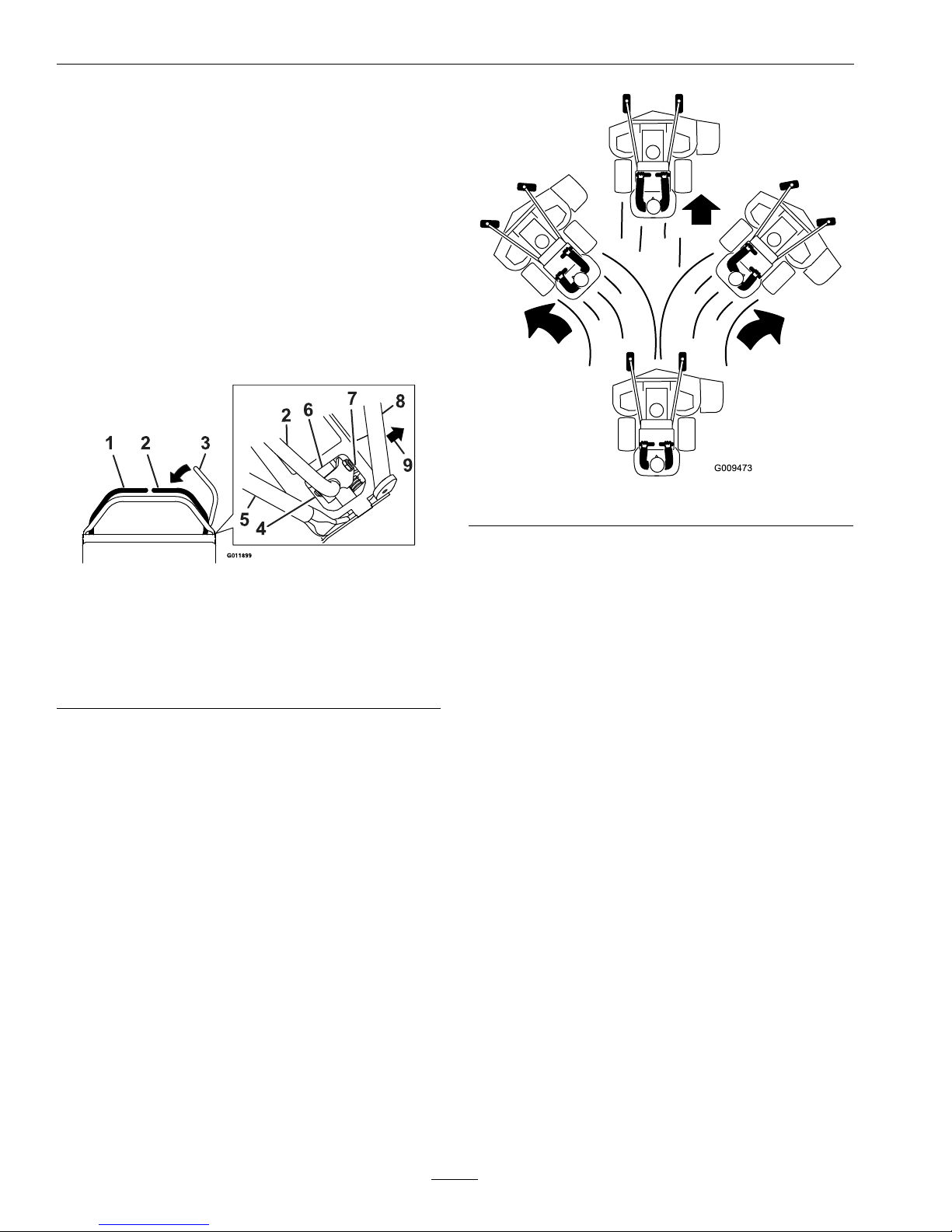
DrivingForward
1.Makesurethemotioncontrolleversareinthe
neutralposition.
2.Releasetheparkingbrake.
3.Tomoveforwardinastraightline,moveboth
leversforwardwithequalpressure.
Figure9
Toturnleftorright,pullthemotioncontrollever
backtowardneutralinthedesiredturndirection.
Themachinewillmovefasterthefartherthe
motioncontrolleversaremovedfromtheneutral
position.
4.Tostop,positionbothmotioncontrolleversin
theneutraloperateposition.
DrivinginReverse
1.Movethemotioncontrolleverstotheneutral
operateposition.
2.Tomoverearwardinastraightline,slowlymove
bothleversrearwardwithequalpressure.
20
Page 21
Operation
Figure10
Toturnleftorright,releasepressureonthe
motioncontrollevertowardthedesiredturn
direction.
3.Tostop,positionbothmotioncontrolleversin
theneutraloperateposition.
AdjustingtheFrontReference/Speed
ControlBar
Adjustthefrontreference/speedcontrolbarfor
desiredmaximumforwardspeed.
1.Stopthemachineandmovethemotioncontrol
leverstotheneutralposition.
2.DisengagethePTO.
3.Unlockthehandlesonbothsidesofthecontrol
towerbypullingoutward(seeFigure11).
Figure11
1.Frontofthemachine
4.Forwardposition—
faster
2.Controltower
5.Backwardposition—
slower
3.Unlock6.Lock
4.Movethebarforwardtoobtainthefastestspeed.
Movethebarbackwardtoobtaintheslowest
speed.
5.Onbothsides,rotateandpushthehandlesinward
tolockthehandlesagainstthecontroltower.
Important:Makesurethehandlesarelocked
inplacesothefrontreference/speedcontrol
bardoesnotmoveduringoperation.
OperatingthePlatform
Themachinecanbeusedwiththeplatforminthe
upordownposition.Itistheoperator’spreference
onwhichpositiontouse.
21
Page 22
Operation
WARNING
Theoperatorplatformisheavyandmay
causeinjurywhenloweringandraising
theoperatorplatform.Theplatformmay
suddenlydropifnotsupportedwhenthe
latchpinispulledout.
•DoNotputyourhandsorngersinthe
platformpivotareawhenloweringor
raisingtheoperatorplatform.
•Makesuretheplatformissupported
whenthelatchpinispulledout.
•Makesurethelatchsecurestheplatform
whenfoldingitintheupposition.Push
ittightagainstthecushionforthelatch
pintolockintoplace.
OperatingtheMachinewiththe
PlatformUp
Operatingthemachinewiththeplatformupis
recommendedwhen:
•Mowingneardrop-off’s
•Mowingsmallareaswherethemachineistoolong
•Areaswithlowoverhangingbranchesorobstacles
•Loadingthemachinefortransport
•Unloadingthemachineaftertransport
•Drivinguporbackingdownslopesorramps.
•Turningintightareaswhereplatformmaycontact
obstacles.
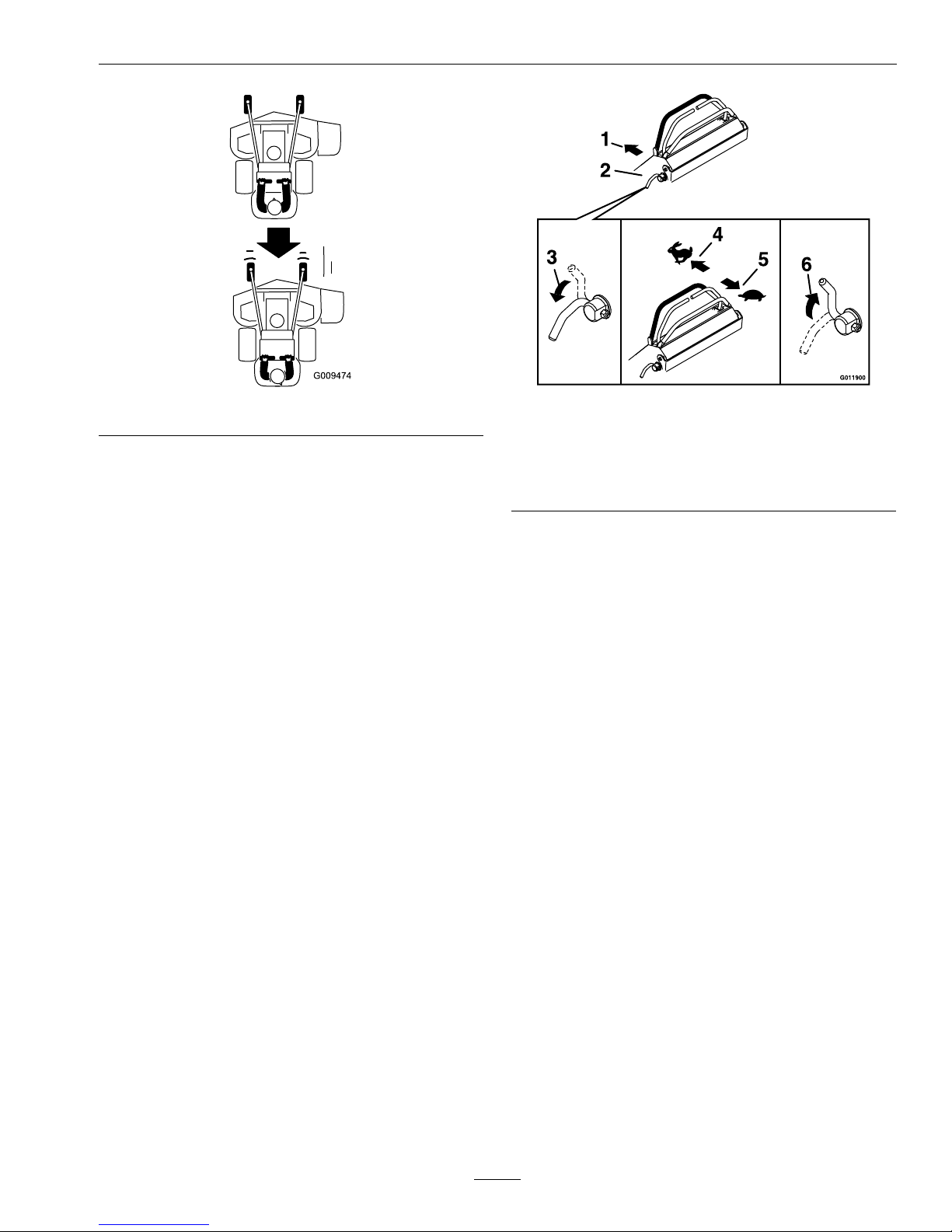
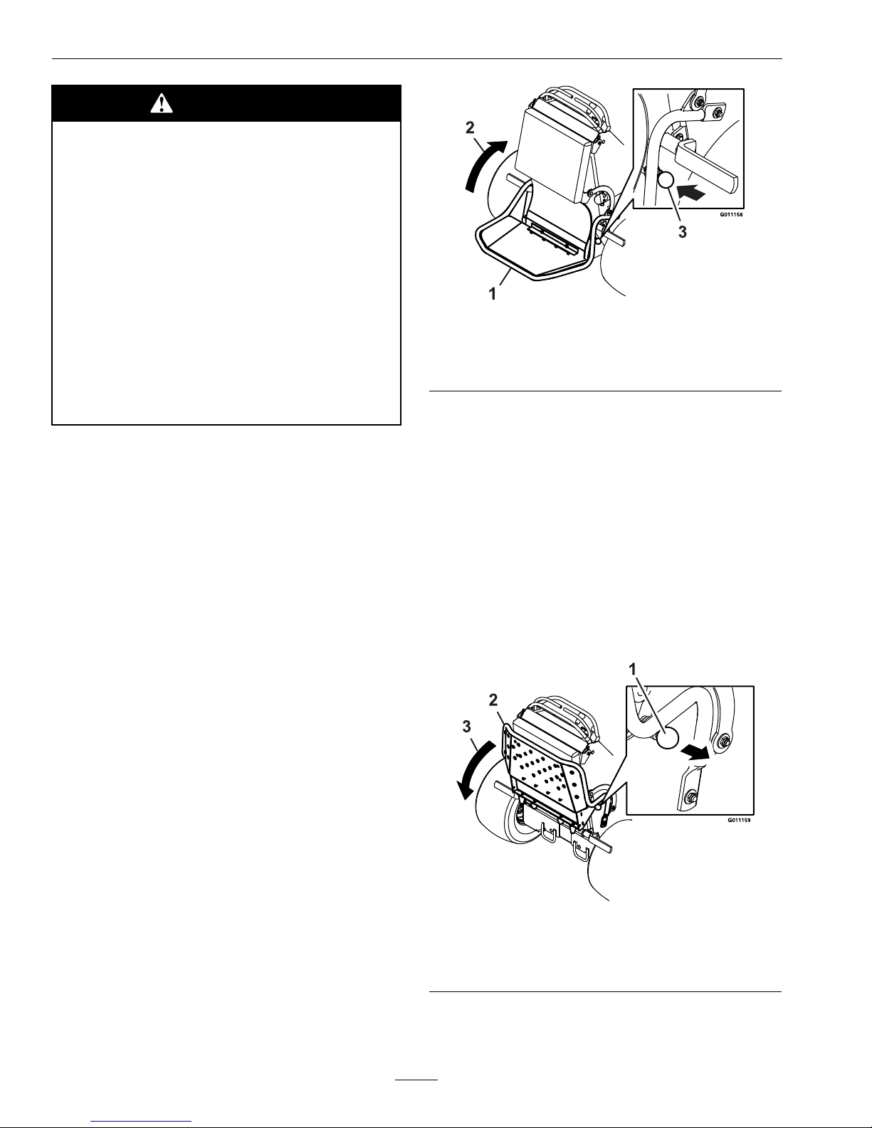
Toraisetheplatform,pullthebottomupwardand
pushittightagainstthecushion.Thelatchpinknob
willsnapinwardtolocktheplatformintoplace(see
Figure12).
Figure12
1.Platform
2.Raiseupward
3.Latchpinknobsnapsinward
OperatingtheMachinewiththe
PlatformDown
Operatingthemachinewiththeplatformdownis
recommendedwhen:
•Mowingmostareas
•Drivingdownslopes
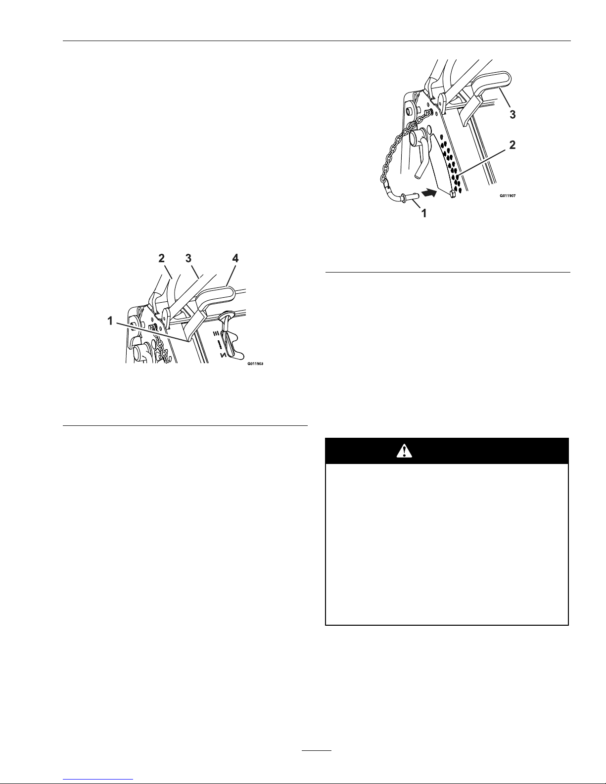
Tolowertheplatform,pushtheplatformforward
againstthecushiontoreleasepressureonthelatch
pin,pulltheknoboutward,andlowertheplatform
(seeFigure13).
Figure13
1.Pulllatchpinknoboutward
2.Platform
3.Lower
22
Page 23
Operation
AdjustingtheCuttingHeight
Thecuttingheightofthemowerdeckisadjusted
from1to5inches(2.5cmto12.7cm)in1/4inch
(6.4mm)increments.
1.Stopthemachineandmovethemotioncontrol
leverstotheneutralposition.
2.DisengagethePTO.
3.Raiseandlockthedecktothe5inch(12.7cm)
transportposition.
Thedeckisraisedbypullingthedecklifthandle
rearwardandtotherighttoplaceitintothe
transportlockposition.
Figure14
1.Transportlockposition
3.Frontreference/speed
controlbar
2.RHMotioncontrollever
4.Decklifthandle
Note:Whenchangingthecuttingheight
positions,alwayscometoacompletestop
anddisengagethePTO.
4.Inserttheheightadjustmentpinintothehole
correspondingtothedesiredcuttingheight.
Seethedecalonthesideofthedeckliftplatefor
cutheights(referenceFigure15).
5.Pullthedecklifthandlerearwardandtotheleft
andslowlyallowthedecktolowertothecutting
height.
Figure15
1.Heightadjustmentpin
3.Decklifthandle
2.Heightofcutholes
Transporting
TransportingaUnit
Useaheavy-dutytrailerortrucktotransportthe
machine.Lockbrakeandblockwheels.Securely
fastenthemachinetothetrailerortruckwithstraps,
chains,cable,orropes.Besurethatthetrailerortruck
hasallnecessarylightingandmarkingasrequiredby
law .Secureatrailerwithasafetychain.
CAUTION
Thisunitdoesnothaveproperturn
signals,lights,reectivemarkings,ora
slowmovingvehicleemblem.Drivingona
streetorroadwaywithoutsuchequipment
isdangerousandcanleadtoaccidents
causingpersonalinjury.Drivingonastreet
orroadwaywithoutsuchequipmentmayalso
beaviolationofStatelawsandtheoperator
maybesubjecttotrafcticketsand/ornes.
DoNotdriveaunitonapublicstreetor
roadway.
23
Page 24

Operation
WARNING
Loadingaunitonatrailerortruckincreases
thepossibilityofbackwardtip-over.
Backwardtip-overcouldcauseseriousinjury
ordeath.
•Useextremecautionwhenoperatinga
unitonaramp.
•Useonlyasingle,fullwidthramp;Do
Notuseindividualrampsforeachside
oftheunit.
•Ifindividualrampsmustbeused,use
enoughrampstocreateanunbroken
rampsurfacewiderthantheunit.
•DoNotexceeda15°anglebetweenramp
andgroundorbetweenrampandtrailer
ortruck.
•Avoidsuddenaccelerationwhiledriving
unituparamptoavoidtippingbackward.
•Avoidsuddendecelerationwhilebacking
unitdownaramptoavoidtipping
backward.
LoadingaUnit
Useextremecautionwhenloadingunitsontrailersor
trucks.Onefullwidthrampthatiswideenoughto
extendbeyondthereartiresisrecommendedinstead
ofindividualrampsforeachsideoftheunit.With
theplatformup,afullwidthrampprovidesasurface
towalkonbehindtheunit.Ifitisnotpossibletouse
onefullwidthramp,useenoughindividualrampsto
simulateafullwidthcontinuousramp.
Rampshouldbelongenoughsothattheangles
betweentherampandthegroundandtherampand
thetrailerortruckdonotexceed15°.Asteeperangle
maycausemowerdeckcomponentstogetcaughtas
theunitmovesfromramptotrailerortruck.Steeper
anglesmayalsocausetheunittotipbackward.If
loadingonornearaslope,positionthetraileror
trucksoitisonthedownsideoftheslopeandthe
rampextendsuptheslope.Thiswillminimizethe
rampangle.Thetrailerortruckshouldbeaslevel
aspossible.
Important:DoNotattempttoturntheunit
whileontheramp,youmaylosecontroland
driveofftheside.
Avoidsuddenaccelerationwhendrivinguparamp
andsuddendecelerationwhenbackingdownaramp.
Bothmaneuverscancausetheunittotipbackward.
24
Page 25

Maintenance
Maintenance
Note:Determinetheleftandrightsidesofthemachinefromthenormaloperatingposition.
WARNING
Whilemaintenanceoradjustmentsarebeing
made,someonecouldstarttheengine.
Accidentalstartingoftheenginecould
seriouslyinjureyouorotherbystanders.
Removethekeyfromtheignitionswitch,
engageparkingbrake,andpullthewire(s)
offthesparkplug(s)beforeyoudoany
maintenance.Alsopushthewire(s)aside
soitdoesnotaccidentallycontactthespark
plug(s).
WARNING
Theenginecanbecomeveryhot.T ouching
ahotenginecancausesevereburns.
Allowtheenginetocoolcompletelybefore
serviceormakingrepairsaroundtheengine
area.
RecommendedMaintenanceSchedule(s)
MaintenanceService
Interval
MaintenanceProcedure
Aftertherst5hours
•Changetheengineoil.
Aftertherst100hours
•Checkwheelhub-slottedtorquespecication.
Aftertherst250hours
•Changethehydrauliclteranduid.
Beforeeachuseordaily
•Checktheengineoillevel.
•Checkthemowerblades.
•Checkthesafetyinterlocksystem.
•Checkforloosehardware.
•Cleantheengineandexhaustsystemarea.
•Cleanthegrassanddebrisbuild-upfromthemachineandcuttingdeck.
•Cleanthegrassbuild-upfromunderthedeck.
Every40hours
•Checkthehydraulicoillevel.
•Checkthetirepressures.
•Checktheconditionofthebelts.
Every50hours
•Checksparkarrester(ifequipped).
Every80hours
•Removeengineshroudsandcleancoolingns.
Every100hours
•Changetheengineoil.(Mayneedmoreoftenundersevereconditions.)
•Checktheelectricclutch.
Every160hours
•Checkthesparkplugs.
Every200hours
•Greasetheliftlinkagepivots.
Every250hours
•Replacetheprimaryaircleanerelement—checksecondaryaircleanerelement;replaceif
dirty.(Mayneedmoreoftenundersevereconditions.SeetheEngineOwner’sManualfor
additionalinformation.)
25
Page 26

Maintenance
MaintenanceService
Interval
MaintenanceProcedure
Every500hours
•Replacethesecondaryaircleanerelement(Mayneedmoreoftenundersevereconditions.
SeetheEngineOwner’sManualforadditionalinformation.)
•Changethehydrauliclteranduid(Every250hours/yearlyifusingMobil115W50)
•Checkwheelhub-slottedtorquespecication.
Monthly
•Checkthebatterycharge.
Yearly
•Greasethefrontcasterpivots.
•Greasethedeckbeltidlerpivot.
•Greasethefrontcasterwheelhubs.
PeriodicMaintenance
CheckEngineOilLevel
ServiceInterval:Beforeeachuseordaily
1.Stopengineandwaitforallmovingpartstostop.
Makesureunitisonalevelsurface.
2.Checkwithenginecold.
3.Cleanareaarounddipstick.Removedipstickand
wipeoiloff.Reinsertthedipstickandpushitall
thewaydownintothetube.DoNotscrewinto
place.Removethedipstickandreadtheoillevel.
4.Iftheoillevelislow ,wipeofftheareaaroundthe
oilllcap,removecapandlltothe“FULL”
markonthedipstick.Useoilasspeciedin
EngineOwner’ sManual.DoNotoverll.
Important:DoNotoperatetheenginewiththe
oillevelbelowthe“LOW”(or“ADD”)markon
thedipstick,oroverthe“FULL”mark.
CheckBatteryCharge
ServiceInterval:Monthly
WARNING
CALIFORNIA
Proposition65Warning
Batteryposts,terminals,andrelated
accessoriescontainleadandlead
compounds,chemicalsknowntotheStateof
Californiatocausecancerandreproductive
harm.Washhandsafterhandling.
Allowingbatteriestostandforanextendedperiodof
timewithoutrechargingthemwillresultinreduced
performanceandservicelife.T opreserveoptimum
batteryperformanceandlife,rechargebatteriesin
storagewhentheopencircuitvoltagedropsto12.4
volts.
Note:Topreventdamageduetofreezing,battery
shouldbefullychargedbeforeputtingawayfor
winterstorage.
Checkthevoltageofthebatterywithadigital
voltmeter.Locatethevoltagereadingofthebatteryin
thetableandchargethebatteryfortherecommended
timeintervaltobringthechargeuptoafullcharge
of12.6voltsorgreater.
Important:Makesurethenegativebattery
cablesaredisconnectedandthebatterycharger
usedforchargingthebatteryhasanoutputof
16voltsand7ampsorlesstoavoiddamaging
thebattery(seechartforrecommendedcharger
settings).
Voltage
Reading
Percent
Charge
Maximum
Charger
Settings
Charging
Interval
12.6or
greater
100%
16volts/7
amps
No
Charging
Required
12.4–12.675–100%
16volts/7
amps
30Minutes
12.2–12.450–75%
16volts/7
amps
1Hour
12.0–12.225–50%
14.4volts/4
amps
2Hours
26
Page 27

Maintenance
Voltage
Reading
Percent
Charge
Maximum
Charger
Settings
Charging
Interval
11.7–12.00–25%
14.4volts/4
amps
3Hours
11.7orless
0%
14.4volts/2
amps
6Hoursor
More
RecommendedJump
StartingProcedure
ServiceInterval:Asrequired
1.Checktheweakbatteryforterminalcorrosion
(white,green,orblue“snow”),itmustbecleaned
offpriortojumpstarting.Cleanandtighten
connectionsasnecessary.
CAUTION
Corrosionorlooseconnectionscancause
unwantedelectricalvoltagespikesatanytime
duringthejumpstartingprocedure.
DoNotattempttojumpstartwithlooseor
corrodedbatteryterminalsordamagetothe
enginemayoccur.
DANGER
Jumpstartingaweakbatterythatiscracked,
frozen,haslowelectrolytelevel,oran
open/shortedbatterycell,cancausean
explosionresultinginseriouspersonalinjury.
DoNotjumpstartaweakbatteryifthese
conditionsexist.
2.Makesuretheboosterisagoodandfullycharged
leadacidbatteryat12.6voltsorgreater.Use
properlysizedjumpercables(4to6AWG)with
shortlengthstoreducevoltagedropbetween
systems.Makesurethecablesarecolorcodedor
labeledforthecorrectpolarity .
CAUTION
Connectingthejumpercablesincorrectly
(wrongpolarity)canimmediatelydamage
theelectricalsystem.
Becertainofbatteryterminalpolarityand
jumpercablepolaritywhenhookingup
batteries.
Note:Thefollowinginstructionsareadapted
fromtheSAEJ1494Rev.Dec.2001–Battery
BoosterCables–SurfaceVehicleRecommended
Practice(SAE–SocietyofAutomotive
Engineers).
WARNING
Batteriescontainacidandproduceexplosive
gases.
•Shieldtheeyesandfacefromthebatteries
atalltimes.
•DoNotleanoverthebatteries.
Note:Besuretheventcapsaretightandlevel.
Placeadampcloth,ifavailable,overanyvent
capsonbothbatteries.Besurethevehiclesdo
nottouchandthatbothelectricalsystemsare
offandatthesameratedsystemvoltage.These
instructionsarefornegativegroundsystemsonly.
3.Connectthepositive(+)cabletothepositive(+)
terminalofthedischargedbatterythatiswiredto
thestarterorsolenoidasshowninFigure16.
27
Page 28

Maintenance
Figure16
1.Positive(+)cableondischargedbattery
2.Positive(+)cableonboosterbattery
3.Negative(–)cableontheboosterbattery
4.Negative(–)cableontheengineblock
5.Boosterbattery
6.Dischargedbattery
7.Engineblock
4.Connecttheotherendofthepositivecabletothe
positiveterminaloftheboosterbattery.
5.Connecttheblacknegative(–)cabletotheother
terminal(negative)oftheboosterbattery.
6.MAKETHEFINALCONNECTIONON
THEENGINEBLOCKOFTHESTALLED
VEHICLE(NOTTOTHENEGATIVEPOST)
AWAYFROMTHEBATTERY .STANDBACK.
7.Startthevehicleandremovethecablesinthe
reverseorderofconnection(theengineblock
(black)connectionisthersttodisconnect).
ReleasetheCushionforRear
Access
ServiceInterval:Asrequired
Thecushioncanbereleasedforrearaccesstothe
machineformaintenanceoradjustment.
1.Lowertheplatform.
2.Removethehairpincotterpinsoneachsideof
thecushion.
3.Pushtheplasticslidestotheinside.
4.Removethecushionandlowerittotheplatform.
5.Performanymaintenanceoradjustmentonthe
machine.
6.Raisethecushionandslideitontothepinson
bothsidesofthemachine(Figure17).
7.Pushtheplasticslidesintothecushionbracket
andsecurethemwithahairpin.
Figure17
1.Plasticslide
2.Cushionbracketwithkeyhole
3.Hairpin
CheckMowerBlades
ServiceInterval:Beforeeachuseordaily
1.Stopengine,waitforallmovingpartstostop,and
removekey.Engageparkingbrake.
2.Liftdeckandsecureinraisedpositionasstatedin
theCleanGrassBuild-UpUnderDecksection.
3.Inspectbladesandsharpenorreplaceasrequired.
4.Reinstalltheblades(iftheywereremoved)inthe
followingorder:
28
Page 29
Maintenance
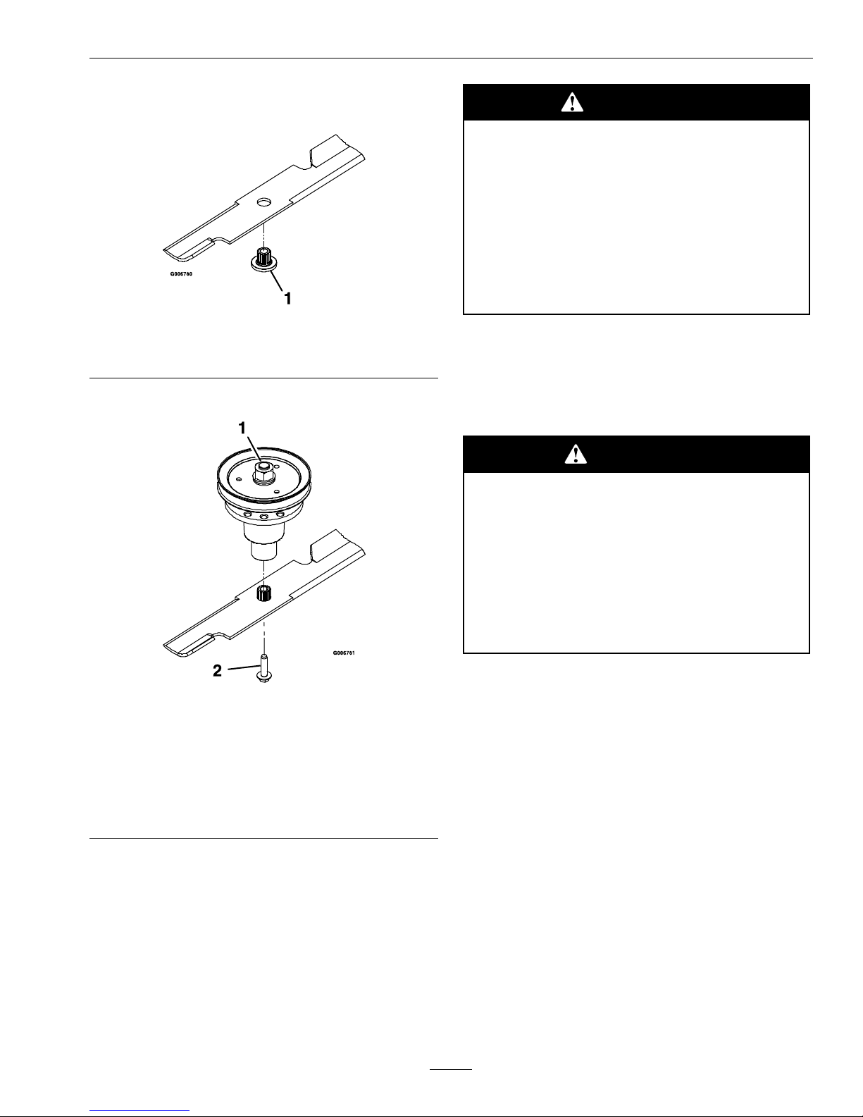
A.Installbushingthroughbladewithbushing
angeonbottom(grass)sideofblade.
Figure18
1.Installbushinginbladepriortoinstallingbushingin
spindle.
B.Installbushing/bladeassemblyintospindle.
Figure19
1.Usewrenchherefor
bladeinstallation.This
nuthasbeentorquedto
140–145ft-lb(190–197
N-m)
2.Torqueto55-60ft-lb
(75-81N-m)Apply
lubricanttothreads
asneededtoprevent
seizing.Copper-based
anti-seizepreferable.
Greaseacceptable
substitute.
C.Applylubricanttothreadsofbladeboltas
neededtopreventseizing.Copper-based
anti-seizepreferable.Greaseacceptable
substitute.Installbladeboltngertight.Place
wrenchonthetopspindlenutthentorquethe
bladeboltsto55-60ft-lb(75-81N-m).
WARNING
Incorrectinstallationofthebladeor
componentsusedtoretainthebladecan
bedangerous.Failuretousealloriginal
componentsandassembledasshowncould
allowabladeorbladecomponenttobe
thrownoutfromunderthedeckresultingin
seriouspersonalinjuryordeath.
AlwaysinstalltheoriginalExmarkblades,
bladebushings,andbladeboltsasshown.
CheckSafetyInterlock
System
ServiceInterval:Beforeeachuseordaily
CAUTION
Ifsafetyinterlockswitchesaredisconnected
ordamagedthemachinecouldoperate
unexpectedlycausingpersonalinjury.
•Donottamperwiththeinterlock
switches.
•Checktheoperationoftheinterlock
switchesdailyandreplaceanydamaged
switchesbeforeoperatingthemachine.
UnderstandingtheSafetyInterlockSystem
Thesafetyinterlocksystemisdesignedtopreventthe
mowerbladesfromrotatingunless:
•Therightsidemotioncontrolleverismovedto
thecenter,operatingposition.
•Thebladecontrolswitch(PTO)ispulledon.
Thesafetyinterlocksystemisdesignedtostop
themowerbladesifyoumoveorreleasetheright
sidemotioncontrolleverintotheneutrallock
position.
•Therightsidemotioncontrolleverismovedto
thecenter,operatingposition,theparkingbrake
isengaged,andthebladecontrolswitch(PTO)is
pulledon.
CheckingtheSafetyInterlockSystem
1.Starttheengine.
2.Settheparkingbrake.
29
Page 30

Maintenance
3.Movethemotioncontrolleversforward.
Theengineshouldinitiateshutdownafter
momentarypause.
4.Starttheengineandreleasetheparkingbrake.
5.Movetherightsidemotioncontrollevertothe
center,operatingposition.
6.Continueholdingtherightsidemotioncontrol
leverinthecenter,operatingpositionandpullup
onthebladecontrolswitch(PTO)andrelease.
Theclutchshouldengageandthemowerblades
beginrotating.
7.Moveorreleasetherightsidemotioncontrol
leverintotheneutralposition.Theblades
shouldstoprotatingandtheengineshould
continuerunning.
8.Pushthebladecontrolswitchdownandmove
therightsidemotioncontrollevertothecenter,
operatingposition.
9.Continueholdingtherightsidemotioncontrol
leverinthecenter,operatingpositionandpullup
onthebladecontrolswitch(PTO)andrelease.
Theclutchshouldengageandthemowerblades
beginrotating.
10.Pushthebladecontrolswitch(PTO)downtothe
offposition.Thebladesshouldstoprotating.
11.Withtheenginerunning,pullupthebladecontrol
switch(PTO)andreleasewithoutholdingright
sidemotioncontrollevertothecenter,operating
position.Thebladesshouldnotrotate.
CheckforLooseHardware
ServiceInterval:Beforeeachuseordaily
1.Stopengine,waitforallmovingpartstostop,and
removekey.Engageparkingbrake.
2.Visuallyinspectmachineforanyloosehardware
oranyotherpossibleproblem.Tightenhardware
orcorrecttheproblembeforeoperating.
ServiceAirCleaner
ServiceInterval:Every250hours—Replace
theprimaryaircleaner
element—check
secondaryaircleaner
element;replaceifdirty.
(Mayneedmoreoften
undersevereconditions.
SeetheEngineOwner’s
Manualforadditional
information.)
Every500hours—Replace
thesecondaryaircleaner
element(Mayneedmore
oftenundersevere
conditions.Seethe
EngineOwner’sManual
foradditionalinformation.)
1.Stopengine,waitforallmovingpartstostop,and
removekey.Engageparkingbrake.
2.SeetheEngineOwner’sManualformaintenance
instructions.
ChangeEngineOil
ServiceInterval:Aftertherst5hours
Every100hours(May
needmoreoftenunder
severeconditions.)
1.Stopengine,waitforallmovingpartstostop,and
removekey.Engageparkingbrake.
2.Drainoilwhileengineiswarmfromoperation.
3.Theoildrainhoseassemblyislocatedontheleft
sideoftheengine.
Placepanundermachinetocatchoil.Removeoil
drainplug.Allowoiltodrainandreplaceoildrain
plug.Torqueplugto20-24ft-lb(27-33N-m).
4.ReplacetheoillterpertheEngineOwner’s
Manual.Cleanaroundtheoillterandcarefully
removethelterbyunscrewingit.Makesureno
oildrainsontothebeltdriveorclutchthrough
theholesintheenginedeck.Beforethenew
lterisinstalled,applyathincoatingofoilonthe
surfaceoftherubberseal.Turnlterclockwise
untilrubbersealcontactsthelteradapter,then
tightenlteranadditional2/3to3/4turn.
5.Cleanaroundoilllcapandremovecap.Fillto
speciedcapacityandreplacecap.
6.Useoilrecommendedinengineowner’smanual.
DoNotoverll.Starttheengineandcheckfor
leaks.Stopengineandrecheckoillevel.
7.Wipeupanyspilledoilfromenginedeck
mountingsurfaces.
CheckHydraulicOilLevel
ServiceInterval:Every40hours
30
Page 31

Maintenance
1.Stopengineandwaitforallmovingpartstostop.
Engageparkingbrake.
2.Cleanareaaroundhydraulicreservoircapand
removecap.Oillevelshouldbetothetopofthe
bafeinsidethetank.Ifnot,addoil.UseExmark
PremiumHydrooil.Replacehydraulicreservoir
capandtightenuntilsnug.DoNotovertighten.
Note:Thebafeislabeled“HOT”and
“COLD”.Theoillevelvarieswiththe
temperatureoftheoil.The“HOT”levelshows
thelevelofoilwhenitisat225°F(107°C).The
“COLD”levelshowstheleveloftheoilwhen
itisat75°F(24°C).Filltotheappropriatelevel
dependinguponthetemperatureoftheoil.For
example:Iftheoilisabout150°F(65°C),llto
halfwaybetweenthe“HOT”and“COLD”levels.
Iftheoilisatroomtemperature(about75°F
(24°C)),llonlytothe“COLD”level.
CheckTirePressures
ServiceInterval:Every40hours
1.Stopengine,waitforallmovingpartstostop,and
removekey.Engageparkingbrake.
2.Checktirepressureindrivetires.
3.Inatedrivetiresto12–16psi(83–110kPa).
4.Semi-pneumaticcastertiresdonotneedtobe
inated.
CheckConditionOfBelts
ServiceInterval:Every40hours
1.Stopengine,waitforallmovingpartstostop,and
removekey.Engageparkingbrake.
2.Removethemowerdeckbeltshieldtocheck
mowerbladedrivebeltcondition.
3.Lookunderenginedecktocheckthepumpdrive
beltcondition.
4.Checkallidlerarmstobesuretheypivotfreely .
LubricateGreaseFittings
Note:Seechartforserviceintervals.
1.Stopengine,waitforallmovingpartstostop,and
removekey.Engageparkingbrake.
2.LubricatettingswithNGLIgrade#2
multi-purposegungrease.
Refertothefollowingchartforttinglocations
andlubricationschedule.
LubricationChart
Fitting
Locations
Initial
Pumps
Numberof
Places
Service
Interval
1.LiftLinkage
Pivots
1–2
7
Every200
hours
2.DeckBeltIdler
Pivot
11
Yearly
3.FrontCaster
WheelHubs
*0
2
*Yearly
4.FrontCaster
Pivots
*0
2
*Yearly
*Seestep3forspeciallubricationinstructionson
thefrontcasterpivots.
3.Lubricatefrontcasterpivotsonceayear.Remove
hexplugandcap.Threadgreasezerkinholeand
pumpwithgreaseuntilitoozesoutaroundtop
bearing.Removegreasezerkandthreadplugback
in.Placecapbackon.
LubricateCasterWheelHubs
ServiceInterval:Yearly
1.Stopengine,waitforallmovingpartstostop,and
removekey.Engageparkingbrake.
31
Page 32
Maintenance
Figure20
1.Sealguard2.Spacernutwithwrench
ats
2.Removecasterwheelfromcasterforks.
3.Removesealguardsfromthewheelhub.
4.Removeoneofthespacernutsfromtheaxle
assemblyinthecasterwheel.Notethatthread
lockingadhesivehasbeenappliedtolockthe
spacernutstotheaxle.Removetheaxle(with
theotherspacernutstillassembledtoit)from
thewheelassembly .
5.Pryoutseals,andinspectbearingsforwearor
damageandreplaceifnecessary.
6.PackthebearingswithaNGLIgrade#1
multi-purposegrease.
7.Insertonebearing,onenewsealintothewheel.
Note:Seals(ExmarkP/N103-0063)mustbe
replaced.
8.Iftheaxleassemblyhashadbothspacernuts
removed(orbrokenloose),applyathreadlocking
adhesivetoonespacernutandthreadontothe
axlewiththewrenchatsfacingoutward.Do
Notthreadspacernutallofthewayontotheend
oftheaxle.Leaveapproximately1/8inch(3mm)
fromtheoutersurfaceofthespacernuttothe
endoftheaxleinsidethenut.
9.Inserttheassemblednutandaxleintothewheel
onthesideofthewheelwiththenewsealand
bearing.
10.Withtheopenendofthewheelfacingup,ll
theareainsidethewheelaroundtheaxlefullof
NGLIgrade#1multi-purposegrease.
11.Insertthesecondbearingandnewsealintothe
wheel.
12.Applyathreadlockingadhesivetothe2ndspacer
nutandthreadontotheaxlewiththewrenchats
facingoutward.
13.T orquethenutto75-80in-lb(8-9N-m),loosen,
thenre-torqueto20-25in-lb(2-3N-m).Make
sureaxledoesnotextendbeyondeithernut.
14.Reinstallthesealguardsoverthewheelhuband
insertwheelintocasterfork.Reinstallcasterbolt
andtightennutfully .
Important:Topreventsealandbearingdamage,
checkthebearingadjustmentoften.Spinthe
castertire.Thetireshouldnotspinfreely
(morethan1or2revolutions)orhaveanyside
play.Ifthewheelspinsfreely,adjusttorqueon
spacernutuntilthereisaslightamountofdrag.
Reapplythreadlockingadhesive.
CheckSparkPlugs
ServiceInterval:Every160hours
Removesparkplugs,checkconditionandresetgaps,
orreplacewithnewplugs.SeeEngineOwner’s
Manual.
ChangeFuelFilter
ServiceInterval:Asrequired
Afuellterisinstalledinthefuellinebetweenthe
fueltankandtheengine.Replacewhennecessary.
ReplacementFilters
KawasakiKawasaki
P/N49019-7005
ChangeHydraulicSystem
FilterandFluid
ServiceInterval:Aftertherst250hours
Every500hours/Yearly
(whichevercomes
rst)thereafter
(Every250hours/Yearlyif
usingMobil115W50)
Note:UseonlyExmarkPartNo.109–4180for
Summeruseabove32°F(0°C)orP/N1-523541for
Winterusebelow32°F(0°C)(RefertoTransmission
sectioninSpecicationsforlterspecications).
1.Stopengine,waitforallmovingpartstostop,and
removekeyorsparkplugwire(s).Engageparking
brake.
32
Page 33
Maintenance
2.Carefullycleanareaaroundlter.Itisimportant
thatnodirtorcontaminationenterhydraulic
system.
3.Unscrewltertoremoveandallowoiltodrain
fromreservoir.
Important:Beforereinstallingnewlter,ll
itwithExmarkPremiumHydrooilandapply
athincoatofoilonthesurfaceoftherubber
seal.
Turnlterclockwiseuntilrubbersealcontactsthe
lteradapter,thentightenthelteranadditional
2/3to3/4turn.
4.FillreservoirasstatedinCheckHydraulicOil
Level.
ExmarkPremiumHydroOilisrecommended.
Refertothechartforanacceptablealternative:
HydroOil
ChangeInterval
ExmarkPremiumHydro
Oil(Preferred)
500Hours
Mobil115W50
250Hours
5.Loosenlter1/2turnandallowasmallamount
ofoiltoleakfromtheoillter(thisallowsairto
bepurgedfromtheoillterandsupplyhosefrom
thehydraulicreservoir).Turnlterclockwise
untilrubbersealcontactsthelteradapter.Then
tightenthelteranadditional2/3to3/4turn.
6.Raisetherearofmachineupandsupportwith
jackstands(orequivalentsupport)justhigh
enoughtoallowdrivewheelstoturnfreely.
CAUTION
Raisingthemowerdeckforserviceor
maintenancerelyingsolelyonmechanical
orhydraulicjackscouldbedangerous.The
mechanicalorhydraulicjacksmaynotbe
enoughsupportormaymalfunctionallowing
theunittofall,whichcouldcauseinjury.
DoNotrelysolelyonmechanicalorhydraulic
jacksforsupport.Useadequatejackstands
orequivalentsupport.
7.Ifeitherdrivewheeldoesnotrotate,oneorboth
ofthechargepumps(locatedonthetopofthe
mainpumpasshowninFigure21)mayhavelost
their“prime”.RefertoHydraulicSystemAir
Purgesection.
Note:DoNotchangehydraulicsystemoil(except
forwhatcanbedrainedwhenchanginglter),unless
itisfelttheoilhasbeencontaminatedorbeen
extremelyhot.
Changingoilunnecessarilycoulddamagehydraulic
systembyintroducingcontaminatesintothesystem.
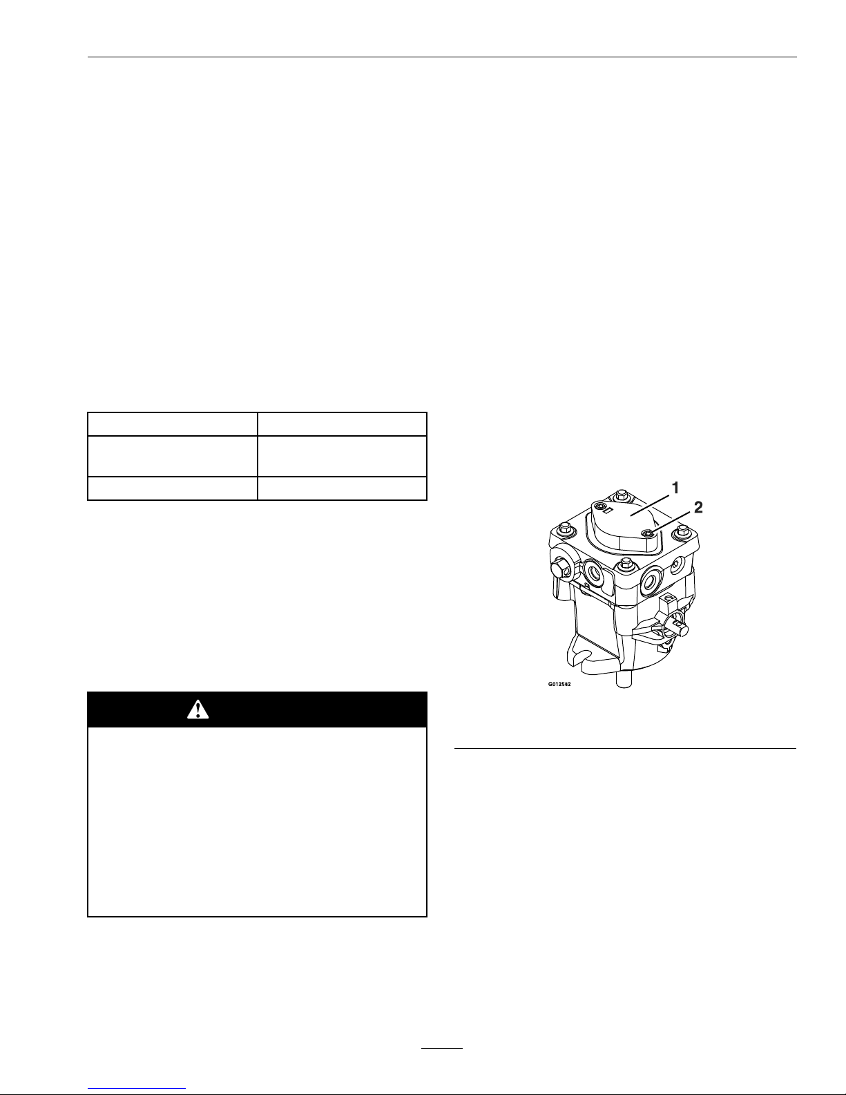
HydraulicSystemAirPurge
ServiceInterval:Asrequired
Airmustbepurgedfromthehydraulicsystem
whenanyhydrauliccomponents,includingoil
lter,areremovedoranyofthehydrauliclinesare
disconnected.
Thecriticalareaforpurgingairfromthehydraulic
systemisbetweentheoilreservoirandeach
chargepumplocatedonthetopofeachvariable
displacementpump(Figure21).Airinotherpartsof
thehydraulicsystemwillbepurgedthroughnormal
operationoncethechargepumpis“primed”.
Figure21
1.Chargepumpcap2.Loosen11/2turnsonly
1.Stopengineandwaitforallmovingpartstostop.
Raisetherearofthemachineupontojackstands
highenoughtoraisethedrivewheelsoffthe
ground.
2.CheckoillevelasstatedinCheckHydraulicOil
Levelsection.
3.Startengineandmovethrottlecontrolaheadto
fullthrottleposition.MoveRHmotioncontrol
leverinward(together)andmovebothlevers
forwardwithequalpressure.
Ifeitherdrivewheeldoesnotrotate,itispossible
toassistthepurgingofthechargepumpby
carefullyrotatingthetireintheforwardposition.
33
Page 34

Maintenance
Note:Itisnecessarytolightlytouchthecharge
pumpcapwithyourhandtocheckthepump
temperature.Ifthecapistoohottotouch,turn
offengine.Thepumpsmaybedamagedifthe
pumpbecomestoohot.
Ifeitherdrivewheelstilldoesnotrotatecontinue
withstep4.
4.Thoroughlycleantheareaaroundeachofthe
chargepumphousings.
5.To“prime”chargepump,loosentwohexsocket
headcapscrews(showninFigure21)11/2turns
only.Makesureengineisnotrunning.Lift
thechargepumphousingupwardandwaitfor
asteadyowofoiltoowoutfromunderthe
housing.Retightenthecapscrews.Dothisfor
bothpumps.
Note:Hydraulicreservoircanbepressurizedup
to5psitospeedthisprocess.
6.Ifeitherdrivewheelstilldoesnotrotate,stop
andrepeatsteps4and5abovefortherespective
pump.Ifwheelsrotateslowly,thesystemmay
primeafteradditionalrunning.Checkoillevel
asstatedinChecktheHydraulicOilLevel
section.
7.Allowunittorunseveralminutesafterthecharge
pumpsare“primed”withdrivesysteminthefull
speedposition.CheckoillevelasstatedinCheck
theHydraulicOilLevelsection.
8.Checkhydrodrivelinkageadjustmentasstatedin
HydroDriveLinkageAdjustmentsectionin
Adjustments.
WheelHub-SlottedNut
TorqueSpecication
ServiceInterval:Aftertherst100hours
Every500hoursthereafter
Whentighteningtheslottednutonthewheelmotor
taperedshaft:
1.Torquetheslottednutto100ft-lb(136N-m).
2.Furthertightenthenutuntilthenextsetofslots
lineupwiththecrossholeintheshaft.
3.Replacecotterpin.
Note:DoNotuseanti-seizecompoundonthe
wheelhub.
CheckSparkArrester
(ifequipped)
ServiceInterval:Every50hours
WARNING
Hotexhaustsystemcomponentsmayignite
gasolinevaporsevenaftertheengineis
stopped.Hotparticlesexhaustedduring
engineoperationmayigniteammable
materials.Firemayresultinpersonalinjury
orpropertydamage.
DoNotrefuelorrunengineunlessspark
arresterisinstalled.
1.Stopengine,waitforallmovingpartstostop,and
removekey.Engageparkingbrake.
2.Waitformufertocool.
3.Ifanybreaksinthescreenorweldsareobserved,
replacearrester.
4.Ifpluggingofthescreenisobserved,remove
arresterandshakelooseparticlesoutofthe
arresterandcleanscreenwithawirebrush(soak
insolventifnecessary).Reinstallarresteron
exhaustoutlet.
ThreadLockingAdhesives
Threadlockingadhesivessuchas“Loctite242”
or“Fel-Pro,Pro-LockNutType”areusedonthe
followingfasteners:
•Pumpsheavesetscrews.
•Sheaveretainingboltinendofenginecrankshaft.
•Casterwheelspacernuts.
MobilHTSGrease(Or
Food-GradeAnti-seize)
MobilHTSgrease(orfood-gradeanti-seize)isused
inthefollowinglocations:
•Betweenthecutterhousingspindleandbearings.
•Betweenthecutterhousingspindleandsheave.
•Undertopcutterhousingbearingguard.
34
Page 35

Maintenance
Copper-BasedAnti-seize
Copper-basedanti-seizeisusedinthefollowing
locations:
•OnthreadsofBladeBolts.SeeCheckMower
Bladessection.
•Betweenenginecrankshaftandpumpandblade
drivesheaves.
•Onclutcharmassemblybetweenbearingsand
shaftandbetweenlowersheaveandshaft.
•Betweenpumpshaftsandsheaves.
DielectricGrease
Dielectricgreaseisusedonallbladetypeelectrical
connectionstopreventcorrosionandlossofcontact.
Adjustments
Note:DisengagePTO ,shutoffengine,waitfor
allmovingpartstostop,engageparkingbrake,and
removekeybeforeservicing,cleaning,ormakingany
adjustmentstotheunit.
CAUTION
Raisingthemowerdeckforserviceor
maintenancerelyingsolelyonmechanical
orhydraulicjackscouldbedangerous.The
mechanicalorhydraulicjacksmaynotbe
enoughsupportormaymalfunctionallowing
theunittofall,whichcouldcauseinjury.
DoNotrelysolelyonmechanicalorhydraulic
jacksforsupport.Useadequatejackstands
orequivalentsupport.
DeckLeveling
Note:Sidetosidedecklevelingshouldbedoneby
anAuthorizedServiceDealer.Smalladjustmentscan
beaccomplishedbyincreasingthetirepressurein
thetireonthelowside.
1.Parkthemachineonalevelsurfaceanddisengage
thebladecontrolswitch.
2.Stopengine,waitforallmovingpartstostop,and
removekey.Engageparkingbrake.
3.Checktheairpressureinthedrivetires.Ifneeded,
adjusttotherecommendedination;referto
CheckingtheTirePressureinDriveSystem
Maintenancesection.
4.Settheheightofcutlevertothe3inch(7.6cm)
position.
5.Raisethedischargedeector.
6.Carefullyrotatethebladesfronttorear.Measure
fromthetipofthefrontbladetothelevelsurface
(Figure22).Thebladesshouldmeasure3inches
(7.6cm).
35
Page 36
Maintenance
Figure22
1.Bladesfronttorear
2.Measurehere
7.Measurebetweentheoutsidecuttingedgesand
theatsurface(Figure23).Ifbothmeasurements
arenotwithin3/16inch(5mm),anadjustmentis
required;contactanAuthorizedServiceDealer.
Figure23
1.Bladessidetoside2.Measurehere
8.Lowerthedischargedeector.
AdjustingtheCuttingDeck
Rake
1.Parkthemachineonalevelsurfaceanddisengage
thebladecontrolswitch.
2.Stopengine,waitforallmovingpartstostop,and
removekey.Engageparkingbrake.
3.Checktheairpressureinthedrivetires.Ifneeded,
adjusttotherecommendedination;referto
CheckingtheTirePressureinDriveSystem
Maintenancesection.
4.Checkandadjustthesidetosidebladelevelif
youhavenotcheckedthesetting;refertoDeck
Leveling.
5.Carefullyrotatethebladesfronttorear
(Figure24).Measurefromthetipofthefront
bladetothelevelsurfaceandthetipoftherear
bladetothelevelsurfaceonallblades.Theblades
shouldbe1/4inch(6.4mm)lowerinthefront
thanintherear.
Figure24
1.Bladesfronttorear
2.Measurehere
6.Loosentherearlocknutsonbothadjustment
rods(Figure25).
Figure25
1.Adjustmentrod3.Frontlocknut
2.Rearlocknut
Note:Makesuretheenginedeckbrackets
arerestingrmlyontherearliftpoints(see
Figure26).Ifitisliftingoff,tightenthefront
locknutoftheadjustingrodontheoppositeside.
36
Page 37
Maintenance
Figure26
1.Rearliftpoints
2.Enginedeckbrackets
7.Toraisethefrontofthemowingdeck,tightenthe
frontlockingnutsbythesameamountonboth
frontadjustingrods.Tightenbothrearlocking
nuts.Checkthesidetosidelevelofthemower
again;refertoDeckLeveling.
Note:Rakeadjustmentsmayaffectthemotion
controlneutralposition.SeetheMotionControl
NeutralAdjustmentandMotionControl
TrackingAdjustmentsectionsinMaintenance.
AdjustingtheRearofthe
Deck
1.Parkthemachineonalevelsurfaceanddisengage
thebladecontrolswitch.
2.Stopengine,waitforallmovingpartstostop,and
removekey.Engageparkingbrake.
3.Checktheairpressureinthedrivetires.Ifneeded,
adjusttotherecommendedination;referto
CheckingtheTirePressureinDriveSystem
Maintenancesection.
4.Settheheightofcuttothe3inch(7.6cm)
position.
5.Carefullyrotatethebladesfronttorear.Measure
fromthetipofthefrontbladetothelevelsurface.
Thebladesshouldmeasure3inches(7.6cm).
6.Ifitdoesnotmeasurecorrectly,locatethe
height-of-cutrodontherightsideofthemachine
(seeFigure27).
Figure27
1.Adjustmentscrew
7.Turntheadjustmentscrewuntilthebladetips
match3inches(7.6cm).
PumpDriveBeltTension
Self-tensioning-Noadjustmentnecessary.
MowerDeckDriveBelt
Tension
Self-tensioning-Noadjustmentnecessary.
ChecktheParkBrake
1.Parkthemachineonalevelsurface.
2.Shutoffengineandwaitforallmovingpartsto
stop.
3.Whentheparkbrakeisreleased,thebrakebars
shouldliftoffthetiresandthehandlevershould
travelforwardtotheendoftheslotinthecontrol
panel.Whenengagingthebrake,thehandlever
shouldtravel3/4inch(19mm)atthecontrol
panelslotwhenthebrakebarsrstcontactthe
tire.Measurethegapfromthefrontofthelever
totheendoftheslotinthecontrolpanelwhen
thebrakebarcontactsthetire.
ParkBrakeAdjustment
Iftheparkingbrakedoesnotholdsecurely ,an
adjustmentisrequired.
1.Parkthemachineonalevelsurface.
2.Shutoffengineandwaitforallmovingpartsto
stop.
3.Disengagetheparkbrake.
37
Page 38
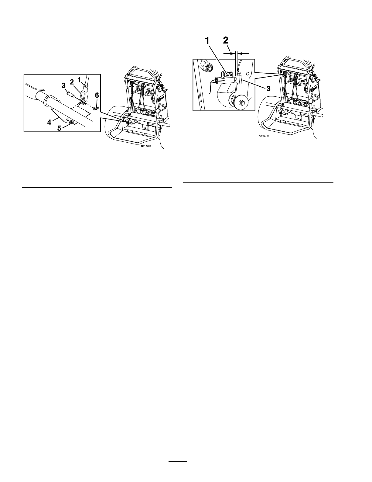
Maintenance
4.Toadjustthebrake,removethehairpin,washer,
andclevispinfromthelowerbrakeleverandyoke
asshowninFigure28.
Figure28
1.Jamnut4.Lowerbrakelever
2.Yoke5.Washer
3.Clevispin
6.Hairpin
5.Loosenthejamnut.
6.Rotatetheyoke.T otightenthebrake,rotatethe
yokeup.Toloosenthebrake,rotatetheyoke
down.
Note:Thebrakerodshouldbethreadedinto
bothyokesthesamedistance.
7.Securetheyoketolowerbrakeleverwiththe
hairpin,washer,andclevispin.
8.Tightenthejamnut.
9.Checkthebrakeoperationagain.
10.Afterthebrakeisadjusted,theleverswitchneeds
tobechecked.
11.Checkthegapbetweenthebrakeleverandthe
switchasshowninFigure29.Thegapneedsto
bean1/8inch(3mm)withthebrakeengaged.
Figure29
1.Switch
3.Brakelever
2.1/8inch(3mm)gap
neededbetweenswitch
andbrakelever
12.Ifneeded,loosenthescrewsholdingtheswitch
andadjusttheswitch.
ElectricClutchAdjustment
ServiceInterval:Every100hours
Theclutchisadjustabletoensureproperengagement
andproperbraking.
1.Stopengine,waitforallmovingpartstostop,
andremovekey.Engageparkingbrake.Allow
themachinetocoolcompletelybeforestarting
theseinstructions.
2.Inserta0.015–0.021inch(0.381–0.533mm)
feelergaugethroughoneinspectionslotinthe
sideoftheassembly.Makesureitisbetweenthe
armatureandtherotorfrictionsurfaces.
3.Thegapshouldbeatleast0.015(0.381mm)and
notmorethan0.021(0.533mm).Ifadjustmentis
needed,thensetat0.015(0.381mm)foreachof
thethreeadjustmentslotpositions.
4.Tightenthelocknutsuntilthereisslightbinding
onthefeelergaugebutitcanbemovedeasily
withintheairgap(seeFigure30).
38
Page 39

Maintenance
Figure30
1.Adjustingnut3.Feelergauge
2.Slot
MotionControlNeutral
Adjustment
Checktoseeifanadjustmentisrequired:
1.Withtheengineoff,turntheignitionswitchto
the“ON”position.
2.LocatetheLCDindicatorinthemessagedisplay.
Figure31
1.NeutralLCDindicator
3.Withthemotioncontrolleversintheneutral
position(seeFigure4)(withnoforceonthelever
eitherforwardorback),theneutralLCDindicator
shouldappear.
4.Iftheindicatorilluminates,movetheRHlever
rstforward,thenbackward,notingtheposition
ofthecontrolleverwhentheindicatordisappears.
Theamountofmovement,bothforwardand
back,shouldbeapproximatelythesame;ifnot,
gotostep6.
5.Iftheindicatordoesnotilluminate,moveboth
motioncontrolleversforwardandthenbackward.
Continuetowatchthemessagedisplayandnote
thepositionofthecontrolswhenitappears.
6.Loosenthelocknutsontheturnbuckleonthe
RHmotioncontrol(asviewedfromtherearof
themachine—seeFigure32).Withtheright
motioncontrolintheneutrallockposition,hold
theLHmotioncontrolinthepositiondetermined
instep4or5.Rotatetheturnbuckleuntilthe
LCDindicatorcomeson.
Figure32
1.Locknut
3.Locknut(LHthread)
2.Turnbuckle
7.Continuetorotatetheturnbuckle,countingthe
turns,untiltheLCDindicatorturnsoff.Rotate
theturnbuckleintheoppositedirectionhalfthe
numberofturnscounted.ReleasetheLHmotion
controlleverandtightenthelocknutsonthe
rightside.
8.AdjusttheturnbuckleontheLHside(asviewed
fromtherearofthemachine—seeFigure33)
untiltheleftcontrolhasapproximatelythesame
naturalneutralpositionastheright.Ifmore
adjustmentisneeded,contactanAuthorized
ServiceDealer.Finaladjustmentoftheleftsideis
doneinthetrackingadjustmentsection.
39
Page 40
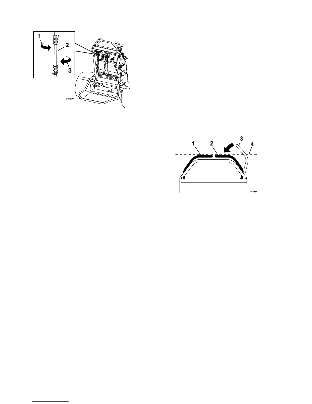
Maintenance
Figure33
1.Rotatetoincreasespeed
2.Turnbuckle
3.Rotatetodecreasespeed
9.Reinstalltherearcushion.
MotionControlTracking
Adjustment
Ifthemachinetravelsorpullstoonesidewhenthe
motioncontrolleversareinthefullforwardposition,
adjustthetracking.
1.Pushbothcontrolleversforwardthesame
distance.
2.Checkifthemachinepullstooneside.Ifitdoes,
stopthemachineandsettheparkingbrake.
3.Releasetherearcushionfromtherearofthe
machine.
4.Placethefrontreference/speedcontrolbarin
themaximumforwardposition.SeeAdjusting
theFrontReference/SpeedControlBarin
Operation.
5.RotatetheturnbuckleontheLHsideofthe
machine(asviewedfromtherearofthemachine
—seeFigure33).
6.Lookingdowntowardstheturnbuckle—rotate
itcounterclockwise,in1/4turnincrements,to
increasespeedorclockwisetodecreasespeed.
7.Drivethemachineandcheckthefullforward
tracking.
8.Repeatsteps5through7untildesiredtracking
isobtained.
9.Reinstalltherearcushion.
AdjustRHMotionControl
HandlePosition
Ifthemotioncontrolleversdonotalignhorizontally,
adjusttherightsidemotioncontrollever.
Note:Adjustthehorizontalalignmentbeforethe
fronttobackalignment.
1.Stopengine,waitforallmovingpartstostop,and
removekey.Engageparkingbrake.
2.Pushtherightmotioncontrolleverdownoutof
lockedneutralposition.
3.Checkifitalignshorizontallywiththeleftmotion
controllever.
Figure34
1.LHMotioncontrollever
2.RHMotioncontrollever
3.RHMotioncontrolleverinneutrallockedposition
4.Checkthehorizontalalignmenthere
4.Toadjusttherightmotioncontrollever
horizontally,thecamneedstobeadjusted.
5.Releasethecushionfromtherearofthemachine.
6.Loosenthenutandboltholdingthecam.
7.Adjustthecamuntilitalignswiththeleftmotion
controlleverandtightenthenutandboltforthe
cam.
40
Page 41

Maintenance
Figure35
1.Switchscrews
2.Nutandbolt
3.Cam
4.Frontreference/speedcontrolhandle
8.Afterthecamisadjusted,theleverswitchneeds
tobechecked.
9.Checkthegapbetweenthecontrolleverand
switchasshowninFigure36.Thegapneeds
tobean1/8inch(3mm)withtherightmotion
controlleverintheneutral,operateposition.
Figure36
1.Switch
2.Cam
3.Rightmotioncontrolleverintheneutraloperateposition
4.1/8inch(3mm)
10.Ifneeded,loosenthescrewsholdingtheswitch
andadjusttheswitch.
11.Tightentheswitchscrews.
CasterPivotBearings
Pre-LoadAdjustment
Removedustcapfromcasterandtightennylocnut
untilwashersareatandbackoff1/4ofaturn
toproperlysetthepre-loadonthebearings.If
disassembled,makesurethespringdiscwashersare
reinstalledasshowninFigure37.
Figure37
1.Springdiscwashers
41
Page 42

Maintenance
Cleaning
CleanEngineandExhaust
SystemArea
ServiceInterval:Beforeeachuseordaily
(Mayberequiredmore
oftenindryordirty
conditions.)
CAUTION
Excessivedebrisaroundenginecoolingair
intakeandexhaustsystemareacancause
engine,exhaustarea,andhydraulicsystem
tooverheatwhichcancreatearehazard.
Cleanalldebrisfromengineandexhaust
systemarea.
1.Stopengine,waitforallmovingpartstostop,and
removekey.Engageparkingbrake.
2.Cleanalldebrisfromrotatingengineairintake
screen,aroundengineshrouding,andexhaust
systemarea.
3.Wipeupanyexcessivegreaseoroilaroundthe
engineandexhaustsystemarea.
RemoveEngineShroudsand
CleanCoolingFins
ServiceInterval:Every80hours
1.Stopengine,waitforallmovingpartstostop,and
removekey.Engageparkingbrake.
2.Removecoolingshroudsfromengineandclean
coolingns.Alsocleandust,dirt,andoilfrom
externalsurfacesofenginewhichcancause
impropercooling.
3.Makesurecoolingshroudsareproperly
reinstalled.Operatingtheenginewithout
coolingshroudswillcauseenginedamagedueto
overheating.
CleanDebrisFromMachine
ServiceInterval:Beforeeachuseordaily
1.Stopengine,waitforallmovingpartstostop,and
removekey.Engageparkingbrake.
2.Cleanoffanyoil,debris,orgrassbuild-uponthe
machineandcuttingdeck,especiallyunderdeck
beltshields,aroundthefueltank,aroundengine
andexhaustarea.
CleanGrassBuild-UpUnder
Deck
ServiceInterval:Beforeeachuseordaily
1.Stopengine,waitforallmovingpartstostop,and
removekey.Engageparkingbrake.
2.Raisedecktothetransport(maximumcutting
height)position.Liftthefrontofunitandsupport
unitusingjackstandsorequivalentsupport.
CAUTION
Raisingthemowerdeckforserviceor
maintenancerelyingsolelyonmechanical
orhydraulicjackscouldbedangerous.The
mechanicalorhydraulicjacksmaynotbe
enoughsupportormaymalfunctionallowing
theunittofall,whichcouldcauseinjury.
DoNotrelysolelyonmechanicalorhydraulic
jacksforsupport.Useadequatejackstands
orequivalentsupport.
3.Cleanoutanygrassbuild-upfromundersideof
deckandindischargedeector.
WasteDisposal
MotorOilDisposal
Engineoilandhydraulicoilarebothpollutantsto
theenvironment.Disposeofusedoilatacertied
recyclingcenteroraccordingtoyourstateandlocal
regulations.
42
Page 43

Maintenance
BatteryDisposal
DANGER
Batteryelectrolytecontainssulfuricacid,
whichispoisonousandcancausesevere
burns.Swallowingelectrolytecanbefatalor
ifittouchesskincancausesevereburns.
•Wearsafetyglassestoshieldeyes,and
rubberglovestoprotectskinandclothing
whenhandlingelectrolyte.
•DoNotswallowelectrolyte.
•Intheeventofanaccident,ushwith
waterandcalladoctorimmediately .
Federallawstatesthatbatteriesshouldnotbeplaced
inthegarbage.Managementanddisposalpractices
mustbewithinrelevantfederal,state,orlocallaws.
Ifabatteryisbeingreplacedoriftheunitcontaining
thebatteryisnolongeroperatingandisbeing
scrapped,takethebatterytoalocalcertiedrecycling
center.Ifnolocalrecyclingisavailablereturnthe
batterytoanycertiedbatteryreseller.
43
Page 44

Troubleshooting
Troubleshooting
Important:Itisessentialthatalloperatorsafetymechanismsbeconnectedandinproperoperating
conditionpriortomoweruse.
Whenaproblemoccurs,donotoverlookthesimplecauses.Forexample:startingproblemscouldbecaused
byanemptyfueltank.
Thefollowingtablelistssomeofthecommoncausesoftrouble.DoNotattempttoserviceorreplacemajor
itemsoranyitemsthatcallforspecialtimingofadjustmentsprocedures(suchasvalves,governor,etc.).Have
thisworkdonebyyourEngineServiceDealer.
Note:WhendisconnectingelectricalconnectorsDoNotpullonthewirestoseparatetheconnectors.
ProblemPossibleCauseCorrectiveAction
1.PTOisengaged.
1.DisengagethePTO .
2.Oneofthespeedcontrolleversarenot
inneutralposition.
2.Ensurethespeedcontrolleverisinthe
neutralposition.
3.Batterydoesnothaveafullcharge.
3.
Chargethebattery.SeeCheck
BatteryChargeandRecommended
JumpStartingProceduresectionsin
Maintenance.
4.Electricalconnectionsarecorroded,loose
orfaulty.
4.Checktheelectricalconnectionsfor
goodcontact.Cleanconnectorterminals
thoroughlywithelectricalcontactcleaner,
applydielectricgreaseandreconnect.
5.Fuseisblown.5.Replacetheblownfuse.
6.NeutralLCDindicatordoesnot
illuminate.
6.Checkreedswitch.
Starterdoesnotcrank.
7.Relayorswitchisdefective.7.ContactanAuthorizedServiceDealer.
1.Fueltankisempty .1.Fillthefueltank.
2.Fuelshutoffvalveisclosed.
2.Openthefuelshutoffvalve.
3.Thethrottleandchokearenotinthe
correctposition.
3.Besurethethrottlecontrolismidway
betweenthe“SLOW”and“FAST”
positions,andthechokeisinthe“ON”
positionforacoldengineorthe“OFF”
positionforawarmengine.
4.Dirtinfuellter.4.Replacethefuellter.
5.Dirt,water,orstalefuelisinthefuel
system.
5.ContactanAuthorizedServiceDealer.
6.Aircleanerisdirty.
6.Cleanorreplacetheaircleanerelement.
7.Electricalconnectionsarecorroded,loose
orfaulty.
7.Checktheelectricalconnectionsfor
goodcontact.Cleanconnectorterminals
thoroughlywithelectricalcontactcleaner,
applydielectricgreaseandreconnect.
8.Relayorswitchisdefective.8.ContactanAuthorizedServiceDealer.
9.Faultysparkplug.
9.Clean,adjustorreplacesparkplug.
Enginewillnotstart,startshard,orfailsto
keeprunning.
10.Sparkplugwireisnotconnected.
10.Checkthesparkplugwireconnection.
1.Engineloadisexcessive.1.Reducethegroundspeed.
2.Aircleanerisdirty.
2.Cleanorreplacetheaircleanerelement.
3.Oillevelinthecrankcaseislow.
3.Addoiltothecrankcase.
4.Coolingnsandairpassagesforthe
engineareplugged.
4.Removetheobstructionsfromthecooling
nsandairpassages.
5.V entholeinthefuelcapisplugged.
5.Cleanorreplacethefuelcap.
6.Dirtinfuellter.6.Replacethefuellter.
Enginelosespower.
7.Dirt,water,orstalefuelisinthefuel
system.
7.ContactanAuthorizedServiceDealer.
44
Page 45

Troubleshooting
ProblemPossibleCauseCorrectiveAction
1.Engineloadisexcessive.1.Reducethegroundspeed.
2.Oillevelinthecrankcaseislow.
2.Addoiltothecrankcase.
Engineoverheats.
3.Coolingnsandairpassagesforthe
engineareplugged.
3.Removetheobstructionsfromthecooling
nsandairpassages.
1.Tirepressureindrivetiresnotcorrect.1.Adjusttirepressureinthedrivetires.
Mowerpullsleftorright(withleversfully
forward).
2.Trackingneedsadjustment.2.Adjustthetrackingbyturningturnbuckle
ontheLHturnbuckleinthedirectionthat
themowerneedstobeadjustedto.Rotate
theturnbucklein1/4turnincrements
untilthemowertrackscorrectly.
1.Bypassvalveisnotclosedtight.1.Tightenthebypassvalve.
2.Driveorpumpbeltisworn,looseor
broken.
2.Changethebelt.
Machinedoesnotdrive.
3.Driveorpumpbeltisoffapulley.3.Changethebelt.
1.Blade(s)notsharp.1.Sharpentheblade(s).
2.Cuttingblade(s)is/arebent.
2.Installnewcuttingblade(s).
3.Mowerdeckisnotlevel.3.Levelmowerdeckfromside-to-sideand
front-to-rear.
4.Undersideofmowerisdirty .4.Cleantheundersideofthemower.
5.Tirepressureindrivetiresnotcorrect.5.Adjusttirepressureinthedrivetires.
6.Bladespindlebent.6.ContactanAuthorizedServiceDealer.
Unevencuttingheight.
7.Tipsofadjacentbladesareatanuneven
cuttingheight.Bladestipsshouldbeeven
within3/16inchwhichisapproximately
onebladethickness.
7.Replaceblades,spindlesand(or)check
fordamagetomowerdeck.
1.Cuttingblade(s)is/arebentorunbalanced.
1.Installnewcuttingblade(s).
2.Blademountingboltisloose.2.Tightentheblademountingbolt.
3.Enginemountingboltsareloose.3.Tightentheenginemountingbolts.
4.Looseenginepulley ,idlerpulley,orblade
pulley.
4.Tightentheappropriatepulley.
5.Enginepulleyisdamaged.5.ContactanAuthorizedServiceDealer.
6.Bladespindleisbent.6.ContactanAuthorizedServiceDealer.
Abnormalvibration.
7.Beltisdamaged.7.Installnewbelt.
1.Drivebeltisoffpulley .1.Checkbeltfordamage;replaceif
necessary.Installdrivebeltandcheck
adjustingshaftsandbeltguidesforcorrect
position.
2.Deckbeltisworn,looseorbroken.2.Installnewdeckbelt.
3.Deckbeltisoffpulley.3.Installdeckpulleyandchecktheidler
pulley,idlerarmandspringforcorrect
positionandfunction.
4.Brokenormissingidlerspring.
4.Replacethespring.
5.Electricclutchoutofadjustment.5.Adjusttheclutchairgap.
Bladesdonotrotate.
6.Damagedelectricclutch.6.ContactanAuthorizedServiceDealer.
45
Page 46

Schematics
Schematics
ElectricalDiagram
FUSE BLOCK
KEY SWITCH
I
AYX B S
MAGNETO
SOLENOID (-)
SOLENOID (+)
B+
REGULATOR
FUEL SOLENOID
ENGINE
G
ROUND
PTO CLUTCH
NEUTRAL
KEY SWITCH
VIEWED FROM
BACK OF SWITCH
KEY SW
SWITCH
PTO SWITCH
OPERATOR
PRESENT SW
PARK BRAKE
SWITCH
HOUR METER
RED
RED
RED
RED
VIOLET
VIOLET
BLUE
GREEN
ORANGE
PINK
PINK
PINK
PINK
PINK
GRAY
TAN
YELLOW
VIOLET
WHITE
BROWN
BROWN
BLACK
BROWN
BLACK
(N/C)
(N/C)
AUXILARY
CONNECTOR
ORANGE
ORANGE
BLACK
1 2 3 4 5
1
1 2 3 4 5 6 7 8
1
1
1
1
1
1
1
2 1
1 2
7
6
5
4
3
2
1
8
11
10
9
8
7
6
5
4
3
2
1
12
2 1
1 2
A B
X
OFF = NO CONNNECTION
ON = B I A AND X Y
START = B I S
Y
A
S
B
I
G012957
46
Page 47

Schematics
ElectricalSchematic
47
Page 48

Schematics
HydraulicDiagram
48
Page 49

General Warranty Conditions and Products Covered
Exmark Mfg. Co. Inc. and its affiliate, Exmark Warranty Company,
pursuant to an agreement between them, jointly warrant on the terms and
conditions herein, that we will repair, replace or adjust any
part on these
products and found by us (in the exercise of our reasonable discretion) to
be defective in factory materials or workmanship.
This warranty may only be assigned or transferred to a second (or third)
owner by an authorized Exmark dealer. The warranty period commences
upon the date of the original retail purchase.
Commercial Warranty Conditions
This warranty applies to Exmark Lazer Z, Lazer Z Advantage Series (AS)
X, and Vantage turf equipment sold in the U.S. or Canada for a period of
three years for commercial usage.
This warranty includes the cost of parts and labor for a period of two
years and the cost of parts for one additional year. This warranty does not
cover pickup and delivery charges to and from any authorized Exmark
Service Dealer.
Consumer Warranty Conditions
This warranty applies to Exmark Lazer Z, Lazer Z AS X, and Vantage
turf equipment sold in the U.S. or Canada for a period of five years or
750 hours (whichever occurs first) for residential usage.
Residential usage means use of the product on the same lot as your home.
Use at more than one location is considered commercial use, and the
commercial use warranty detailed above would apply.
This warranty only includes the cost of parts and labor. For the first
warrantable service repair, Exmark will cover up to $45 for associated
pick-up and delivery charges to and from any authorized Exmark Service
Dealer. Additional transportation charges may apply, contact your Dealer
for details.
Warranty Exceptions
Warranty Exceptions Warranty Period
• Bags, Belts and Tires 90 days
• Battery 1 Year Prorated
• Engine (except Kohler EFI) 2 years*
• Kohler EFI Engine 3 years*
* The Engine warranty is covered by the engine manufacturer. Please
refer to the engine manufacturer’s warranty statement that is included in
the literature packet.
Items and Conditions Not Covered
This warranty does not cover the following:
• Any damage or deterioration due to normal use, wear and tear, or
exposure.
• Cost of regular maintenance service or parts, such as filters, fuel,
lubricants, tune-up parts, and adjustments.
• Any product or part which has been altered or misused or required
replacement or repair due to normal wear, accidents, or lack of proper
maintenance.
• Any repairs necessary due to use of parts, accessories or supplies,
including gasoline, oil or lubricants, incompatible with the turf
equipment or other than as recommended in the operator's manual or
other operational instructions provided by Exmark.
There are no other express warranties except for engine and special
emission system coverage.
All warranty work must be performed by an authorized Exmark Service
Dealer using Exmark approved replacement parts.
Instructions for Obtaining Warranty Service
The product must be registered with original proof of purchase by an
Exmark Service Dealer before obtaining any warranty service.
Contact any Exmark Service Dealer to arrange service at their dealership.
To locate a dealer convenient to you, access our website at
www.exmark.com. U.S. or Canada customers may also call
402-223-6375.
If for any reason you are dissatisfied with the Service Dealer’s analysis or
with the assistance provided, contact us at:
Exmark Customer Service Department
The Exmark Warranty Company
2101 Ashland Avenue
Beatrice, NE 68310
402-223-6375 or
service@exmark.com
Owner’s Responsibilities
If your product requires warranty service it must be returned to an
authorized Exmark service dealer within the warranty period. This
warranty extends only to turf equipment operated under normal
conditions. You must read the operator’s manual. You must also properly
service and maintain your Exmark product as described in the operator’s
manual. Such routine maintenance, whether performed by a dealer or by
you, is at your expense.
General Conditions
The sole liability of Exmark and Exmark Warranty Company with respect
to this warranty shall be repair or replacement of defective components as
set forth herein. Neither Exmark nor Exmark Warranty Company
shall be liable for any incidental or consequential loss or damage.
Such damages include but are not limited to:
• Expenses related to gasoline, oil or lubricants.
• Travel time, overtime, after hours time or other extraordinary repair
charges or charges relating to repairs or replacements outside of
normal business hours at the place of business of the authorized
Exmark Service Dealer.
• Rental of like or similar replacement equipment during the period of
any warranty, repair or replacement work.
• Any telephone or telegram charges or travel charges.
• Loss or damage to person or property other than that covered by the
terms of this warranty.
• Any claims for lost revenue, lost profit or additional cost as
a result of a claim of breach of warranty.
• Attorney's fees.
No Claim of breach of warranty shall be cause for cancellation or
rescission of the contract of sale of any Exmark mower.
All implied warranties of merchantability (that the product is fit for
ordinary use) and fitness for use (that the product is fit for a
particular purpose) are limited to the duration of the express
warranty.
Some states do not allow exclusions of incidental or consequential
damages, or limitations on how long an implied warranty lasts, so the
above exclusions and limitations may not apply to you.
This warranty gives you specific legal rights, and you may also have
other rights which vary from state to state.
Exmark Lazer Z, Lazer Z Advantage Series X, and Vantage Turf Equipment
3 Year Limited Commercial Warranty
5 Year or 750 Hours Limited Consumer Warranty
G4500-590_C
49
Page 50

50
Page 51
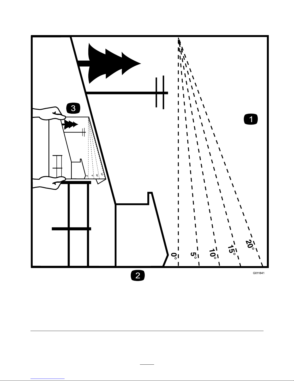
G011841
Figure38
Thispagemaybecopiedforpersonaluse.
1.Themaximumslopeyoucansafelyoperatethemachineonis20degrees.Usetheslopeindicatortodeterminethe
degreeofslopeofhillsbeforeoperating.DoNotoperatethismachineonaslopegreaterthan20degrees.Fold
alongtheappropriatelinetomatchtherecommendedslope.
2.Alignthisedgewithaverticalsurface,atree,building,fencepole,etc.
3.Exampleofhowtocompareslopewithfoldededge.
51
Page 52

MI D-MOUNT RIDING ACCE SSORIES AND OPTIONS
SEE EXMARK’S COMPLETE LINE OF ACCESSORIES AND OPTIONS
WALK-BEHIND ACCESSORIES AND OPTIONS
GRASS CATCHER
MICRO-MULCH SYSTEM
TURF STRIPER
STANDON
CUSTOM RIDE SEAT SUSPENSION SYSTEM
FULL SUSPENSION SEAT
DECK LIFT ASSIST KIT
HITCH KIT
LIGHT KIT
12
V POWER PORT
MICRO-MULCH SYSTEM
OPERATOR CONTROLLED DISCHARGE
ROLL OVER PROTECTION SYSTEM (ROPS)
SUN SHADE
TRASH CONTAINER
TURF STRIPER
ULTRA VAC COLLECTION SYSTEM
ULTRA VAC QUICK DISPOSAL SYSTEM
OU T-FRONT RIDING ACCESSORIES AND OP TIONS
CUSTOM RIDE SEAT SUSPENSION SYSTEM
DUAL-TAIL WHEEL
FLOOR PAN EXTENDER
HITCH KIT
LIGHT KIT
MICRO-MULCH SYSTEM
ROLL OVER PROTECTION SYSTEM (ROPS)
SNOW BLADE
SNOWBLOWER
SUN SHADE
TRASH CONTAINER
ULTRA VAC COLLECTION SYSTEM
ULTRA VAC QUICK DISPOSAL SYSTEM
WEATHER CAB
PlaceModelNo.andSerialNo.
LabelHere(IncludedintheLiterature
Pack)orFillinBelow
DatePurchased
EngineModelNo.andSpec.No.
ModelNo.EngineSerialNo.(E/No)
SerialNo.
©2010ExmarkMfg.Co.,Inc.
IndustrialParkBox808
Beatrice,NE68310
AllRightsReserved
PartNo.4500-648Rev.B
(402)223-6300
Fax(402)223-5489
PrintedintheUSA
www.exmark.com
 Loading...