

Page 1
Page 2

WARNING
POTENTIAL HAZARD
♦ This product is a piece of power equipment.
WHAT CAN HAPPEN
♦ Failure to follow safe operating pr actices can result in serious
operator injury or even death.
HOW TO AVOID THE HAZARD
♦ Keep all shields, guards and safety devices (especially the grass
discharge system) in place and in proper working condit ion.
♦ Stop engine and remove spark plug wire(s) or r emove key and
wait for all moving parts to stop before adjusting, servicing, or
performing maintenance.
♦ If mower deck becomes clogged, stop engine and remove spark
plug wire(s) or remove key and wait for all m oving par ts to stop
before cleaning blockage.
♦ Keep hands, feet and clothing away from power driven parts.
♦ Keep off mower unless seat platf o r m is pr ovided.
♦ Keep others off mower.
Exmark reserves the right to make changes or add improvements to its products at any time
without incurring any obligation to make such chang es to products manufactured previously.
Exmark, or its distributors and dealer s, accept no responsibility for variations which may be evident
in the actual specifications of it s pr oduct s and t he statements and descriptions contained in this
publication.
2
Page 3
EXMARK PARTS PLUS
EFFECTIVE DATE: September 1, 1995
Program
If your Exmark dealer does not have the Exmark part in stock,
Exmark will get the parts to the dealer the next business day or the
part will be FREE* Guaranteed!!
How the Program Works
1. If dealer does not have part in stock for a "down" unit at
the time of request by customer, the dealer contacts his
distributor by 1:00 p.m., local time, and requests Exmark
Parts Plus
2. Distributor ships part(s) to dealer or customer, as
requested by dealer, same day, overnight UPS Distributor
bills dealer for part and freight charges where applicable.
shipment of six (6) line items or less.
PROGRAM
3. If distributor does not have the part(s) in stock to satisfy
Exmark Parts Plus
p.m., central time, with an Exmark Parts Plus
order, he contacts Exmark by 3:00
order of six
(6) line items or less.
4. If order is received by 3:00 p.m. central time, Exmark ships part(s) direct to dealer or customer, as requested by
distributor, same day, overnight UPS Exmark bills the distributor for parts and shipping charges, where
applicable.
5. The customer pays for the part and freight
if it is shipped under the Exmark Parts Plus
and if it arrives in
accordance to the program.
6. Who pays for the part and freight if it fails to arrive overnight in accordance to the program?
A. Under any circumstance the customer does not pay.
B. If the part does not arrive overnight due to:
1. The dealer not submitting the Exmark Parts Plus
order to his Exmark distributor by 1:00 p.m., the
dealer pays for the part and freight.
2. The Distributor being unable to ship the part the same day or not submitting the Exmark Parts Plus
order to Exmark by 3:00 p.m., central time, the Distributor pays for the part and freight.
3. Exmark being unable to ship the part and the Exmark parts order is received by 3:00 p.m., central time,
Exmark pays for the part and freight.
4. If the part does not arrive overnight due to the shipper (UPS), the shipper pays for the freight and
Exmark pays for the part.
The following restrictions apply -- The Exmark Parts Plus
Program is available only through participating
Exmark Dealers and applies only to orders submitted on this program Monday through Thursday. Parts Plus service is
available only in the 48 contiguous United States. UPS has initiated a Saturday delivery program to many areas of the
continental United States and can be requested for an overnight shipment on Friday to be delivered Saturday. The next
day air charge, plus the Saturday delivery fee will be the responsibility of the purchaser. Exmark Mfg. will assume no
responsibility for Saturday delivery shipments. To qualify, all Exmark Parts Plus
3:00 p.m., central time. Orders must be six (6) line items or less. Exclusions from the Exmark Parts Plus
orders must be received by Exmark by
Program are:
Any wholegood or accessory in its entirety, engines and engine replacement parts, 5-speed Peerless transmissions and
5-speed transaxles, hydraulic or hydrostatic wheel motors, cutter decks and engine decks or any item exceeding United
Parcel Service size and weight restrictions.
Due to UPS restrictions, aerosol spray paint is considered a hazardous material and cannot be shipped via UPS next day
or Second Day Air.
Exmark Manufacturing stocks a limited supply of parts for transaxles, pumps and wheel motors. These parts can be
ordered for Next Day Air shipment but will not be guaranteed per the Parts Plus Program.
3
Page 4

OPERATOR'S MANUAL
This manual contains assembly, operating, m aint enance, adjustment and safety instruct ions
for your Exmark Ultra Vac.
BEFORE OPERATING YOUR ULTRA VAC, CAREFULLY READ AND UNDERSTAND
THIS MANUAL AND THE OPERATOR’S MANUAL FOR YOUR LAZER HP MOWER IN THEIR
ENTIRETY.
By following the operating, maintenance and safety instructions, you will prolong the life of
your Ultra Vac, maintain its maximum ef ficiency and promote safe operation.
If additional information is needed, or should you require trained mechanic service, contact
your authorized Exmark equipment dealer or dist r ibut or .
All Exmark equipment dealers and distribut or s ar e kept informed of the latest methods of
servicing and are equipped to provide prompt and efficient service in the field or at their service
stations. They carry ample stock of service parts or can secure them promptly for you from the
factory.
All Exmark parts are thoroug hly test ed and inspect ed before leaving the factory, however,
attention is required on your part if you are to obtain the fullest measure of satisfaction and
performance.
4
Page 5

TABLE OF CONTENTS
Description Page
1. Safety
1.1 Safety Alert Symbol ................................................................6
1.2 Training...................................................................................6
1.3 Preparation ..........................................................................6-7
1.4 Safety Signs............................................................................7
2. Specifications
2.1 Model Number ........................................................................ 7
2.2 Dimensions.............................................................................8
2.3 Bagging System......................................................................8
3. Assembly Instructions
3.1 Assembly Diagram.................................................................. 9
3.2 Install Drive Kit......................................................................10
3.3 Install Hood Assembly and Bags..........................................10
3.4 Assemble Tubes...................................................................10
3.5 Install Blower Assembly...................................................10-11
4. Operation
4.1 Pre-Start................................................................................11
4.2 Mowing.............................................................................11-12
4.3 Bagger Removal for Side Discharge.....................................12
4.4 Transporting.....................................................................12-14
5. Maintenance
5.1 Periodic Maintenance ...........................................................14
6. Parts Lists
6.1 Decals...................................................................................15
6.2 Blower Assembly..............................................................16-17
6.3 Hood and Bag Assembly..................................................18-19
6.4 Drive Kit Assembly................................................................ 20
6.5 Adapter Kit 103-0328............................................................20
7. Warranty.................................................................................21-22
5
Page 6

1. SAFETY
1.1 SAFETY ALERT SYMBOL
THIS SAFETY ALERT S YMBOL IS USED BOTH IN THIS MANUAL AND ON
THE MACHINE TO IDENTIFY IMPORTANT SAFETY MESSAGES WHICH MUST BE
FOLLOWED TO AVOID ACCIDENTS. THIS
The safety alert symbol appears above information which alerts you of unsafe actions or
situations and will be followed by the word DANGER, WARNING, or CAUTION.
When used with t he word DANGER: IT DENOTES THAT AN EXTREME HAZARD
EXISTS WHICH WOULD RESULT IN HIGH PROBABILITY OF DEATH OR
IRREPARABLE INJURY IF PROPER PRECAUTIONS ARE NOT TAKEN.
When used with t he word WARNING: IT DENOTES THAT A HAZARD EXISTS WHICH
CAN RESULT IN INJURY OR DEATH IF PROPER PRECAUTIONS ARE NOT TAKEN.
When used with t he word CAUTION: IT DENOTES A REMINDER OF SAFETY
PRACTICES OR DIRECTS ATTENTION TO UNSAFE PRACTICES WHICH COULD
RESULT IN PERSONAL INJURY IF PROPER PRECAUTIONS ARE NOT TAKEN.
ALERT SYMBOL MEANS:
ATTENTION! BECOME ALERT!
YOUR SAFETY IS INVOLVED!
1.2 TRAINING
1.2.1 Regard the Exmark Ultra Vac as a piece of power equipment and teach this regard t o
all who operate this unit.
1.2.2 Before operating your Ultra Vac, carefully read and understand this manual and the
operator’s manual for your Lazer HP in their entirety.
1.2.3 Read the instructions carefully. Familiarize yourself with the cont r ols and the proper
use of the equipment.
1.2.4 Never allow children, teenagers, or people unfamiliar with these inst r uctions to use the
equipment.
1.2.5 Avoid mowing while people, especially children, or pets, are nearby. Keep in mind t hat
the operator or user is responsible for accidents or hazards occurring to other people
or their property.
1.3 PREPARATION
1.3.1 The use of personal protective equipment , such as (but not limited to) protect ion for
the eyes, ears, feet and head is recommended.
CAUTION
POTENTIAL HAZARD
♦ This machine produces sound levels in excess of 85
dBA at the operator’s ear when in operation.
WHAT CAN HAPPEN
♦ Exposure to sound levels of 85 dBA or above for
extended periods of time can cause hearing loss.
HOW TO AVOID THE HAZARD
♦ Wear hearing protection when operating this machine.
6
Page 7
1.3.2 While mowing, always wear substantial footwear and long trousers. Do not operate
equipment when barefoot or when wearing open sandals.
1.3.3 Thoroughly inspect t he ar ea where the equipment is to be used and remove all
stones, sticks, wires, bones and other f oreign objects which may cause personal injury
to the operator or bystanders or damag e t he equipment.
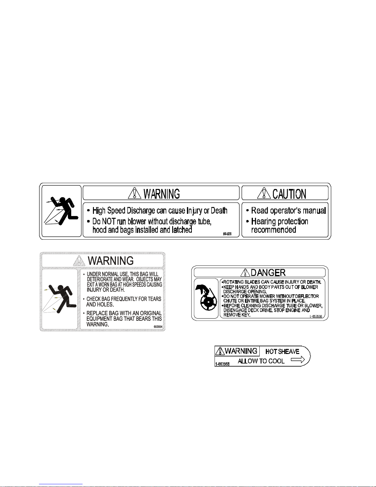
1.4 SAFETY SIGNS
1.4.1 Keep all safety signs legible. Remove all grease, dirt and debris from safety signs and
instructional labels.
1.4.2 Safety signs must be replaced if t hey are m issing or illegible.
1.4.3 When new components are installed, be sur e t hat current safety signs are affixed to
the replaced components.
1.4.4 New safety signs may be obtained from your authorized Exmark equipment dealer or
distributor or from Exmar k Mfg. Co. Inc.
1.4.5 Safety signs may be affixed by peeling of f the backing to expose the adhesive
surface. Apply only to a clean, dry surface. Smooth to remove any air bubbles.
1.4.6 Familiarize yourself with the following safety signs and inst r uct ion labels. They are
critical to the safe operation of your Exmark commercial mower.
PART NO. 1-653554
LOCATION: Rear of Bags
2. SPECIFICATIONS
2.1 MODEL NUMBER:
LHPUV4448
Use with drive kit: 44” deck – 1-651361
Note: Lazer HP model LHP4818KC Serial Nos. below 176621 will also require adapter kit 103-0328
PART NO. 103-0220
LOCATION: Top of Blower
PART NO. 1-653556
LOCATION: Side of Blower Housing (2 Places)
PART NO. 1-653558
LOCATION: Top of Idler Arm
48” deck – 1-651359 (Lazer HP Serial Nos. below 203,376)
48” deck – 1-651360 (Lazer HP Serial Nos. 203,376 & higher )
LHPUV52
Use with drive kit: 52” deck – 1-651360
7
Page 8

2.2 DIMENSIONS
44” deck 48” deck 52” deck
2.2.1 Overall unit length w/ UltraVac 91.76”
(233.07 cm)
2.2.2 Overall unit width w/ UltraVac 58.47”
(148.51 cm)
91.76”
(233.07 cm)
61.73”
(156.79 cm)
(236.22 cm)
2.3 BAGGING SYSTEM
2.3.1 Weight: 110 lbs. (50 kg)
2.3.2 Collections bins: 2 commercial grade, clot h m esh bags with reinforced bottoms.
Capacity: 8 bushels (two 4-bushel bags)
2.3.3 Dump Mechanism: Manual lift off
2.3.4 Blower tube: 6” diamet er , fixed, abrasion resistant molded polyethylene
2.3.5 Impeller: 5-bladed, 7-gauge abrasion resistant steel, with vertical axis.
Impeller bearings: 1” (2. 54 cm ) sealed “non-greaseable bearings”
93.00”
66.47”
(168.83 cm)
8
Page 9

3. ASSEMBLY INSTRUCTIONS
3.1 ASSEMBLY DIAGRAM
Ref. No. Qty Description
1 Ref Engine Guard 44,48 only
2 1 Bagger Mount Weldment
3 8 5/16 – 18 X 1.00 Hex Head Screw
4 1 Hood Assembly
5 2 Bag Assembly
6 1 Upper Tube
7 1 Lower Tube Assembly
8 3 #10 – 24 X .75 Truss Head Screw
9 3 #10 Flat Washer
10 3 #10 – 24 Nyloc Nut
11 1 Blower Assembly
12 Ref Rear Weight 52 only
13 Ref Spacer 52 only
14 8 5/16 – 18 X 1.75 Hex Head Screw
15 4 5/16-18 x 18 Whizlock Nut
16 2 Clevis Pin
17 2 Hair Pin
9
Page 10

3.2 INSTALL DRIVE KIT
1. Install drive kit (PN 1-651361, 1-651360, or 1-651359 depending on deck size) per the
instructions included in the kit.
NOTE: The original belt shield stud must be removed for belt clearance.
3.3 INSTALL HOOD ASSEMBLY AND BAGS
44 and 48 inch units (52 inch units skip to st ep 3)
Note: W hen installing Ultra Vac on Lazer HP model LHP4818KC with serial numbers below
176621, refer to additional necessary instruct ions included in adapt er kit 103-0328.
1. Remove and discard the (8) bolts t hat retain the “HOT” engine guard shield (Item 1).
Keep the nuts for use in Step 2.
2. Install the Bagger Mount Weldment (Item 2) and engine guard shield using the 5/16-18 x 1
Screws provided (Item 3) and whizlock nuts removed in step 1. – continue at step 6.
52 inch units
3. Remove and discard the (8) bolts that retain the rear weight (Ite m 12) . Keep the whizlock
nuts for use in step 5.
4. Install the Bagger Mount Weldment (Item 2) to the rear of t he frame using (4) 5/16 – 18
X1.00 screws (Item 3) and (4) 5/16 – 18 whizlock nuts (I t em 15). Use only the bottom
four holes on the Bagger Mount Weldment
5. Install the Rear Weight (Item 12) and spacer (Item 13) from the drive kit using the (8) 5/16
– 18 X1.75 screws (Item 14) and whizlock nuts removed in step 3.
All units
6. Slide tube ends of Hood Assembly (Item 4) int o t he tubes of the mount weldment. Install
(2) clevis pins (Item 16) throug h holes in tubes. Retain with (2) Hair Pins (Item 17) .
7. Hang the (2) Bag Assemblies ( I t e m 5) from the slots in the Bagg er Upright. Close and
latch hood.
3.4 ASSEMBLE TUBES
Note: W hen installing Ultra Vac on Lazer HP model LHP4818KC with serial number below
176621, refer to additional necessary instruct ions included in adapt er kit 103-0328.
1. Assemble the Upper (Item 6) and Lower (Item 7) Tubes using the (3) #10-24 x .75 Tr uss
head Screws (Item 8), (3) #10 washers (Item 9) , and ( 3) #10-24 Nyloc Nuts (Item 10). Screw
head should be installed to the inside of the tube to pr ovide minimu m obst r uction to flow.
Make sure the hole with the arrow on the Upper Tube aligns with the dimple in the Lower
Tube to place the turnout on the Upper Tube in the correct position.
For units with a 44” deck: Slide Upper Tube over Lower Tube until edge of Upper Tube
matches up with dimple in Lower Tube labeled 44.
For units with a 48” & 52” deck: Slide Upper Tube over Lower Tube until edge of Upper
Tube matches up with dimple in Lower Tube labeled 48, 52.
3.5 INSTALL BLOWER ASSEMBLY
1. Remove the belt g uide on the blower (Item 11). (See Figure 1)
2. Install the belt (fr om the Drive Kit) onto the Blower
Assembly (Item 11) as shown.
FIGURE 1
BELT ROUTING
10
Page 11

3. Reinstall the belt g uide r e m oved in Step 1.
4. Remove Discharge chute by pulling the hairpin and chute pivot pin (f r om the Drive Kit
installed in section 3.2).
5. Remove the Belt Cover on the right side of the deck. Install the Blower by inserting the
mounting pin into the tube welded to the rear corner of the deck. Pivot the blower until t he
front pin engages the slot in the deck. Adjust the position of the front pin if necessary to
engage the slot. Use the latch to lock the blower in this position. Adjust tension on lat ch
to draw blower up to deck, yet allow release by hand.
6. Pull the idler release handle and install the belt in the upper groove of the deck sheave.
7. Install the Belt Cover using the two knobs. Install the discharge tube assembly by slipping
the upper end into the hood, then sliding the lower end over the blower discharge
opening. Use the latch to retain t he lower end to the blower.
8. Follow the operation instructions in Section 4 to run the unit. Run the unit with the blades
and blower engaged for 2 minutes. Diseng age the blades, shut off the motor, and
remove the key.
9. Remove the belt cover and check to make sure that the belt is riding near the center of
the flat idler on the idler arm . If the belt is not riding near the center of the idler, rem ove
the blower, and bend the idler arm slightly. Reinstall the blower and belt cover and
perform steps 8 and 9 again to verify belt position.
WARNING
POTENTIAL HAZARD
♦ An uncovered discharge opening will allow objects to
be thrown in operator’s or bystander’s direction.
Also, contact with blade could occur.
WHAT CAN HAPPEN
♦ Thrown objects or blade contact can cause serious
injury or kill you or bystanders.
HOW TO AVOID THE HAZARD
♦ Never operate mower unless discharge chute or
entire grass collection system is installed.
DANGER
POTENTIAL HAZARD
♦ There are rotating blades in the blower and under
the mower deck.
WHAT CAN HAPPEN
♦ Blade contact can cause serious operator or
bystander injury or even death.
HOW TO AVOID THE HAZARD
♦ Keep hands and feet out of blower openings and out
from under the mower or mower deck.
♦ Shut off the deck dr ive, st op the engine, and wait for
all moving parts to stop before clear ing obstructions.
11
Page 12

4. OPERATION:
4.1 PRE-START
1. Ensure the blower, belt cover, bags, tube and hood are in good condition, pr oper ly
attached, and latched.
4.2 MOWING
1. Blower operates when deck drive is engaged.
2. To remove the bags, shut off deck drive and stop the engine. Open the hood and remove
the bags by lifting up on the rear of the bag, then unhooking t he front clip. Empty bags by
inverting them.
3. Reinstall bags, close and latch the hood before continuing mowing.
4.3 BAGGER REMOVAL FOR SIDE DISCHARGE:
1. Shut off the deck drive, stop engine, remove key and wait for all moving parts t o stop.
2. Remove the discharge tube by releasing the latch at the blower. Slide t he t ube off the
blower outlet and remove the upper end from the hood.
3. Remove the Belt cover by loosening the (2) knobs.
CAUTION
POTENTIAL HAZARD
♦ The deck sheave will become very hot
WHAT CAN HAPPEN
♦ Touching a hot deck sheave can cause severe burns.
HOW TO AVOID THE HAZARD
♦ Allow the deck sheave to cool completely before
removing the belt.
4. Pull the idler release handle and remove the belt from t he deck sheave.
5. Unlatch the front end of the blower. Pivot the blower back and lift it off the deck.
6. Install the discharge chute using the chute pivot pin and hair pin ( See Figure 2).
7. Install the belt cover and tighten the (2) k nobs.
8. Remove the hair pins and clevis pins from the tubes of the m ount weldment.
9. Lift the bag and hood assembly off t he m ount.
The machine can now be used for side discharge mowing.
FIGURE 2
DISCHARGE CHUTE INSTALLATION
12
Page 13

4.4 TRANSPORTING
4.4.1.1 Transport ing a Unit: Use a heavy-duty trailer or truck to tr anspor t the machine.
Lock brake and block wheels. Securely fasten t he machine to the trailer or truck
with straps, chains, cable, or ropes. Be sure that the trailer or truck has all
necessary lighting and marking as required by law.
Secure a trailer with a safety chain.
POTENTIAL HAZARD
♦ This unit does not have proper turn signals, lights, reflective
markings, or a slow moving vehicle emblem. These items
are required to drive on a public street or roadway.
WHAT CAN HAPPEN
♦ Driving on a street or roadway without such equipment is
dangerous and can lead to accidents causing personal injury.
♦ Driving on a street or roadway without such equipment may
also be a violation of State laws and the operator may be
subject to traff ic tickets and/or fines.
HOW TO AVOID THE HAZARD
♦ Do not drive a unit on a public street or roadway.
CAUTION
WARNING
POTENTIAL HAZARD
♦ Loading a unit on a trailer or truck increases the possibility of
backward tip-over.
WHAT CAN HAPPEN
♦ Backward tip-over of the unit could cause serious injury or
death.
HOW TO AVOID THE HAZARD
♦ Use extreme caution when operating a unit on a ramp.
♦ Use only a single, full width ramp; DO NOT use individual
ramps for each side of the unit .
♦ If individual ramps must be used, use enough ram ps t o
create an unbroken ramp surf ace wider than t he unit .
♦ DO NOT exceed a 15° angle between ramp and ground or
between ramp and trailer or truck.
♦ Avoid sudden acceleration while driving unit up a ramp to
avoid tipping backward.
♦ Avoid sudden deceleration while backing unit down a ramp to
avoid tipping backward.
4.4.2 Loading a Unit: Empty grass bags before attempting to load unit on tr ai ler or truck.
Use extreme caution when loading units on trailers or t r ucks. One full width ramp that is
wide enough to extend beyond the rear tires is required instead of individual ramps for
each side of the unit. The lower rear section of the tractor fr am e extends back between
the rear wheels and serves as a stop for tipping backward. Having a full width ramp
provides a surface for the frame members to contact if the unit starts to tip backward. If
it is not possible to use one full width ramp, use enoug h individual ramps to simulate a
full width continuous ramp.
13
Page 14

Ramp should be long enough so that the angles between the ramp and the ground and
the ramp and the trailer or tr uck do not exceed 15°. A steeper angle may cause mower
deck components to get caught as the unit moves from ramp to t r ailer or t ruck. Steeper
angles may also cause the unit to tip backward. If loading on or near a slope, position
the trailer or truck so it is on the down side of the slope and the ramp extends up the
slope. This will minimize the ramp angle. The t railer or truck should be as level as
possible.
DO NOT attempt to tur n t he unit while on the ramp, you may lose control and drive off
the side.
Avoid sudden acceleration when driving up a ramp and sudden deceleration when
backing down a ramp. Both maneuvers can cause the unit to tip backward.
5. MAINTENANCE:
5.1 PERIODIC MAINTENANCE
IMPORTANT: Before conducting any maintenance, shut off deck drive, stop the engine,
remove the key, and wait for all moving parts to stop.
5.1.1 Blower Housing/Impeller.
Service Interval: Daily.
Inspect for wear or damage daily. Replace or r epair worn part s as needed.
5.1.2 Idler Bushing s .
Service Interval: 25 Hours.
Lubricate with 1-2 pumps of SAE No. 2 multi- pur pose grease.
5.1.3 Bags.
Service Interval: Daily
.
5.1.4 Belts.
a) Inspect the belt posit ion on the idler arm.
The idler arm may become bent during use or t ransport. A bent idler arm could
cause the belt to jump off of the idler and be damaged.
1) Make sure the belt cover is installed and run t he blower for one to two minutes.
2) Shut off the deck drive, stop t he engi ne, remove key and wait for all
3) If the belt is not riding near the center of the idler, r em ove the blower, and bend
4) Reinstall the blower and belt cover and repeat steps 1-3 until the belt is positioned
WARNING
POTENTIAL HAZARD
♦ Under normal use the bag will deteriorate and wear.
Objects could exit a worn bag at high speeds.
WHAT CAN HAPPEN
♦ Thrown objects can cause serious injury or kill you or
bystanders.
HOW TO AVOID THE HAZARD
♦ Check bag frequently for tears and holes. Replace
worn bag.
Service Interval: 50 Hours.
moving parts to stop. Remove the belt cover and check to make sur e t hat the
belt is riding near the center of the flat idler on the idler arm.
the idler arm slightly.
near the center of the idler.
14
Page 15

b) Inspect the belt for damage or wear. Replace with the belt with one of the following.
5.1.5 Clean muf fler and rear frame area.
POTENTIAL HAZARD
♦ Muffler gets very hot.
WHAT CAN HAPPEN
♦ Excessive debris accumulated in the muffler area
6. PARTS LISTS
6.1 DECALS
44” deck – PN 1-653332
48” deck – PN 1-653333
52” deck – PN 1-653438
Service Interval: Daily
WARNING
could catch fire causing property damag e and
potentially injuring you or others.
Ref.
No.
Part No. Description Req'd.
1 1-653557 Decal, Ultra Vac………………..1
2 103-0220 Decal, Warning Impeller……… 1
3 1-653558 Decal, Hot Sheave……………..1
4 1-373066 Decal, Patent Pending…………1
5 1-653546 Decal, Exmark…………………. 1
6
1-653556 Decal, Warning Discharge…….2
15
Qty.
Page 16

6.2 BLOWER ASSEMBLY
16
Page 17

6.2BLOWER ASSEMBLY (cont.)
Ref.
No.
Part No. Description Req'd.
Qty.
Ref.
No.
Part No. Description Req'd.
Qty.
1∇ 1-652340-03 Blower mount wldmt 44”, 48”.1 33 103-0126 Bushing, Locator.......................1
1-652444-03 Blower mount wldmt 52”…… 1 34 3257-32 5/8x3/16 #61 Woodruff key ......1
∇
2 1-652351-03 Impeller wldmt....................... 1 35 1-654560 Cover, bearing (1-653485) with
3 1-653346 Bearing, SPH. OD................. 2 decal .........................................1
4 1-513013 Housing, flange..................... 4 36 3296-29 5/16-18 nyloc nut......................2
5◆ 103-1047 Sheave, blower..................... 1 37 3256-3 5/16x7/8 OD flat washer...........2
6 1-654459 Upper housing weldment 38 3274-18 5/16-18x1.25 Soc. Hd Screw....1
(1-652345) with decals..........1 39
1-803075 #10-24x.75 CRTH Screw..........3
7 1-653331 Spring, idler........................... 1 40 1-809112 #10-24 whizlock nut..................3
8 3290-357 3/8-16 whizlock nut ............... 8 41 1-803076 1/4-20x.75 CRTH Screw...........2
9 323-7 3/8-16 x 1.25 screw .............. 1 42 3274-105 3/8-16x1.75 Soc But Hd Screw 1
10 323-11 3/8-16 x 2.25 screw .............. 3 43 1-353050 Pin, Grass Catcher ...................1
11 323-12 3/8-16 x 2.50 screw .............. 2 44 1-806323 Roll Pin .....................................1
12 3256-4 Flat washer -.438x1.00x.083 4 45 1-653596-03 Plate, Blower Backing...............1
13 1-653356 Chute, blower........................ 1 46 1-811006 Zerk, 1/8 – 28 straight...............1
14 1-353054 Latch, grass catcher ............. 1 47 3256-24 3/8 Flat washer.........................1
15 3296-39 3/8-16 nyloc nut .................... 1 48 1-653443-03 Plate, Filler 52” only…………….1
16 1-653322 Idler, inside............................1 49 114439 Pop Rivet 52” only………….…. 2
17 103-0130 Bushing, idler pivot................1 50 3217-6 5/16-18 nut ...............................1
18 1-653352-01 Bumper ................................. 1 51 103-1103 Idler, Flat...................................1
19 1-654559 Idler Assy with bushings, 52 3290-500 #10-24 x .62 CRPH Screw .......4
zerk, and decal...................... 1 53 323-8 3/8 – 16 x 1.50 screw ...............1
20 3230-18 5/16-18 x .62 carriage bolt.... 6 54 1-653600 Bearing .....................................2
21 1-513208 Spring - disk.......................... 1 55 1-653407 Tube, lower...............................1
22 3219-6 5/8-18 nut.............................. 1 56 1-653406 Tube, upper 44”,48”................1
23 3220-5 1/2-20 Jam nut...................... 1
1-653540 Tube, upper 52”......................1•
24 1-513435 Spring - disk.......................... 1 57 1-653429 Latch Assy (Latch & Catch)......1
25 1-653365 Spacer...................................1 58 3296-2 #10-24 Nyloc Nut......................3
26 1-653366 Hub....................................... 1 59 3256-14 #10 Flat Washer.......................6
27 32128-20 5-16-18 whizlock nut............. 6
28 3290-500 #10-24x.62 CRPH Screw...... 2
29
321-3 1/4-20x.62 Hex SCREW....... 8 103-0400 Blower Assy, 52
30 32128-33 1/4-20 whizlock nut ............... 15
103-0401 Blower Assy, 44/48
(includes items 1-54) ................1
(includes items 1-54) ................1
31 1-303334 5/16 Spring disk washer........ 1
32 3229-11 1/4-20x.62 Carr. bolt RHSN…...5
Exmark red touch up spray paint - P/N 1-850337
Use antiseize on bore of sheave.
◆
∇ Includes items 43 and 44
Also used in Adapter Kit 103-0328 on 48” deck Lazer HP model LHP4818KC Serial Number 176621 &
•
below.
¦
Kit 103-0583 is available to add or repair the welded on accessory mounting tube on all 44”-72” decks.
17
Page 18

6.3 HOOD AND BAG ASSEMBLY
18
Page 19

6.3 HOOD AND BAG ASSEMBLY (cont.)
Ref.
No.
Part No. Description Req'd.
1 1-653396 Hood......................................1
Qty.
Ref.
No.
Part No. Description Req'd.
Qty.
29 1-653529-03 Frame, bag .............................1
2 1-653397-03 Stiffener, bagger top..............1 30 114973-03 Hanger, bag............................ 1
3 1-652395-03 Hinge wldmt...........................2 31 114974-03 Clamp .....................................1
4 114967 Screen...................................1 32 3230-1 5/16-18x.75 Carriage bolt.......2
5 114439 3/16x.5 Pop rivet ...................38 33 3296-29 5/16-18 nyloc nut .................... 2
6 1-803075 #10-24x.75 CRTH Screw ......10 34 1-654389 Cloth bag ................................ 1
7 3256-14 .219x.500x.049 Flat washer ..14 35 1-653566 Bag handle..............................1
8 3296-2 #10-24 nyloc nut....................10 36 3229-1 1/4-20x.75 Carriage bolt .........2
9 1-653561 Seal, chute ............................1 37 1-653036 Washer .344x1.75x.062 pltd... 2
10 1-653598-03 Clamp, seal ...........................1 38 3296-42 1/4-20 nyloc nut....................... 2
11 1-653425 Seal .......................................1 39 1-653404 Catch ......................................1
12 1-653400-03 Support, screen.....................1 40 3290-500 #10-24x.625 CRPH Screw......2
13 1-653519 Mount, latch...........................1 41 1-809112 #10-24 whizlock nut................ 2
14 1-653036 Washer .344x1.75x.062 pltd .2 42 1-652414-03 Bag support wldmt.................. 1
15 321-4 1/4-20x.75 Hex Head Screw .6 43 32128-33 1/4-20 whizlock nut................. 1
16 32128-33 1/4-20 whizlock nut................6 44 1-523420 Bumper ................................... 1
17 1-653403 Latch......................................1 45 1-652308-03 Bagger mount weldment.........1
18 1-653535 Latch reinforcement ..............1 46 322-5 5/16-18x1 Screw 44”, 48” only 8
19 321-11 1/4-20x2.0 Hex Head Screw .1 322-9 5/16-18x1.75 Screw 52” only.8
21 3296-42 1/4-20 nyloc nut.....................3
322-12 5/16-18x2.50 Screw................8
•
22 321-6 1/4-20x1.00 Hex Head Screw2 47◆ 1-654597 Hood assembly – service only 1
23 1-652305-03 Bagger upright wldmt ............1 48 1-808289 Clevis Pin................................2
24 3256-2 Flat washer .312x.734x.065…2 49 1-806005 Hair Pin...................................2
25 1-633545 Spacer.................................... 2 50 32128-20 5/16-18x1 whizlock nut 52”only4
26 1-653544 Spring..................................... 2
103-0325-03 Tube, Spacer..........................2
51•
27 322-2 5/16-18x.62 Hex Hd Screw .... 4 52* 1-654390 Bag Assembly.........................1
28 1-653528-03 Plate, backing......................... 1
◆ Includes items 1,2,4,7,12,13,18 riveted together and Decal
• Used in Adapter Kit 103-0328 for Lazer HP model LHP4818KC below Serial Number 176621 only
* Includes items 29 through 38.
19
Page 20

6.4 DRIVE KIT ASSMEBLY
Ref. Quantity Included in Each Kit
No. Part No. Description 103-1313 103-1314 103-1315 103-1317
1 1-653363 Pin, Chute Pivot 1 1 1 1
2 1-806003 Pin, Hair 1 1 1 1
3 1-402106 Wld, Chute 48" SD 1
4 1-805517 2.25 O.D. Washer 1
5 1-523385 Knob, Belt Shield 2 2 2 2
6 1-653439 Sheave, Blower drive (52") 1
1-653362 Sheave, Blower Drive (48") 1 1
1-653309 Sheave, Blower Drive (44") 1
7 1-653438 Belt, Blower (52") 1
1-653333 Belt, Blower (48") 1 1
1-653332 Belt, Blower (44") 1
8 103-1316 Cover, Belt (44" and 48") 1 1 1
103-1318 Cover, Belt (52") 1
9 1-653532-03 Spacer, Counterweight 1
10 322-2 5/16-18x.62 Hex Head Screw 1 1 1 1
6.5 ADAPTER KIT 103-0328 For Lazer HP model LHP4818KC before serial number 176621.
Part No. Description Qty
103-0325-03 Tube, Spacer 2
1-653540 Tube, Upper 1
322-12 5/16-18x2.50 Screw 8
20
Page 21

7. WARRANTY
Limited Warranty
Exmark Commercial Turf Equipment
Exmark Mfg. Co. Inc. and its affiliate, Exmark Warranty Company, pursuant to an agreement between
them, jointly warrant on the terms and condit ions herein, that we will repair, replace or adjust any part
manufactured by Exmark and found by us (in the exercise of our reasonable discretion) to be defective
in factory material or workmanship.
This warranty is limited to one year from the date of original retail pur chase ( 90 days for rental use) for
any Exmark mower that is used for commer cial or any other incom e pr oducing purpose. The blade
spindle assemblies will be warranted for three years, one year parts and labor with an additional two
years parts only, from date of original retail purchase against defects in materials or workmanship. T he
hydrostatic traction drive system, excluding hoses, will be warranted for t wo full years from date of
original retail purchase against defects in materials or workmanship. We will extend the Peerless 5speed transmission manufacturer' s warranty from 90 days to one year. Belts and tires are warranted for
90 days against defects in materials or workmanship.
The engine warranty is covered by its respective engine manufactur er . Please refer to the engine
manufacturers warranty statement that is included in the literature packet. We are not authorized to
handle warranty adjustments on engines. Engine warranties should be referred to the nearest
authorized service outlet of the engine manufacturer.
This warranty extends only to the original retail purchaser of the equipment. This warrant y may not be
assigned or transferred without t he pr ior express writt en consent of Exmark and Exmark Warranty
Company. The warranty period commences upon the date of t he or iginal retail purchase.
The Exmark turf equipment, including any defective part, m ust be returned to an authorized Exmark
service dealer within the warranty period. The warranty shall extend to the expense of repair or
replacement (as determined by us) of t he defective part, including labor. The warrant y shall not extend
to the expense of delivering the mower to the dealer for warranty work nor the expense of retur ning it
back to the owner after repair or replacement. Our responsibilit y in respect t o claims is limited to
making the required r epair s or r eplacem ents, and no claim of breach of warranty shall be cause for
cancellation or rescission of the contract of sale of any Exmark mower. Proof of purchase may be
required by the dealer to substantiate any warranty claim. All warranty work must be performed by an
authorized Exmark service dealer.
This warranty extends only to turf equipment oper ated under normal conditions and properly serviced
and maintained. The warranty expressly does not cover: (i) any damage or deterior ation due to
normal use, wear and tear, or exposure; (ii) normal maintenance services, such as oil change,
cleaning, lubrication; adjustment; (iii) replacement of ser vice items, such as oil, lubricants, spark plugs,
or other items subject to norm a l ser vice replacement; (iv) damage or defects ar ising out of or relating
to misuse, neglect, alterat ion, negligence or accident; (v) repair or replacement arising from operation
of or use of the turf equipment which is not in accordance with operating instructions as specified in the
operator's manual or other operational instructions provided by Exmark; (vi) repair or replacem ent
arising as a result of any operation from turf equipm ent that has been altered or modified so as to, in
the determination of Exmark or Exmark W ar ranty Company, adversely affect the operation,
performance or durability of t he equipment or that has altered, m odified or affected t he t ur f equipment
so as to change the intended use of the pr oduct ; ( vii) r epair or replacement necessitated by use of
parts, accessories or supplies, including g asoline, oil or lubricants, incompatible with the turf equipment
or other than as recommended in the operat or ' s m anual or other operational instructions provided by
Exmark; (viii) repairs or replacements resulting from parts or accessories which have adversely
affected the operat ion, per formance or durability of the t ur f equipment; or (ix) damag e or defects due
to or arising out of repair of turf equipm ent by person or persons other than an authorized Exmark
service dealer or the installation of parts other than genuine Exmark or Exmark r ecommended parts.
21
Page 22

As a condition to this warranty, customer shall have read the operator ' s m anual and shall have
completed and returned to Exmark Warranty Company, within the prescr ibed t im e, the Exmark
warranty registration.
The sole liability of Exmark and Exmark Warranty Company with respect to this warranty shall be
repair and replacement as set for th herein. Neither Exmark nor Exmark Warr ant y Company shall have
any liability for any other cost, loss or damage, including but not limited to, any incidental or
consequential loss or damage. In par ticular, we shall have no liability or responsibility for: (i) expenses
relating to gasoline, oil or lubr icant s; (ii) loss, cost or expense relating to transportation or delivery of
turf equipment from the location of owner or location where used by owner to or from any author ized
Exmark service dealer; (iii) travel time, overt im e, after hours time or other extr aor dinary repair charges
or charge relating to repair s or r eplacem ents outside of normal business hours at the place of business
of the authorized Exmark service dealer; ( iv) r ent al of like or similar replacement equipment during the
period of any warranty, repair or replacement work; (v) any telephone or telegram charges or tr avel
charges; (vi) loss or damage to person or property other than that covered by the terms of this
warranty; (vii) any claims for lost revenue, lost profit or additional cost as a result of a claim of breach
of warranty; or (viii) attorney's fees.
There are no representations or warranties which have been authorized and provided to the buyer of
the turf equipment, other than as set forth in t his warrant y. Any and all statements or representations
made by any seller of this equipment, including t hose set forth in any sales literature or m ade or ally by
any sales representative, are superseded by the terms of this warranty. Any affirmation of fact or
promise made by Exmark , Exmark Warranty Company or any of their representatives to the buyer
which relates to the goods that are the subject of this warranty shall not be regarded as part of the
basis of the bargain and shall not be deemed to create any express warranty that such goods shall
conform to the affirmation or promise.
THERE ARE NO UNDERSTANDINGS, AGREEMENTS, REPRESENTATIONS, OR WARRANT IES,
EXPRESS OR IMPLIED (INCLUDING BUT NOT LIMITED TO ANY REGARDING THE
MERCHANTABILITY OR FIT NESS FOR A PARTICULAR PURPOSE), NOT SPECIFIED HEREIN,
RESPECTING THE EQUI PMENT WHICH IS THE SUBJECT OF THIS WARRANTY.
This warranty applies to all Exmark turf equipment sold in the United States and Canada and int ended t o
be used for commercial purposes.
22
Page 23

SERVICE RECORD
Date Description of Work Done Service Done By
Page 24

SEE EXMARK’S COMPLETE
LINE OF PRODUCTS FOR TURF CARE
LAZER Z
®
LAZER Z® HP
TURF RANGER
TURF TRACER
®
®
TURF TRACER® HP
VIKING HYDRO
METRO
®
METRO® HP
SELF STEERING SULKY
ULTRA VAC
™
GRASS CATCHER
MICRO-MULCH
©2000 EXMARK MFG. CO. INC. PART NO. 1-850656 REV B
INDUSTRIAL PARK BOX 808 (402) 223-6300
BEATRICE, NE 68310 FAX (402) 223-5489
ALL RIGHTS RESERVED PRINTED IN U.S.A.
™
ACCESSORY
MFG . CO . INC.
®
 Loading...