

Exmark Laser Z Ultra Vac, Ultra Vac Laser Z XP, Lazer Z 52, Lazer Z 60, Lazer Z XP 60 Operator's & Parts Manual
...Page 1
MFG. CO. INC.
For Serial Nos.
370,000 & Higher
®
on the purchase of your new Exmark
equipment. This product has been carefully designed and
manufactured to give you a maximum amount of dependability
and years of trouble-free operation. If additional information
is needed, or should you require trained mechanic service,
contact your authorized Exmark equipment dealer or distributor.
If you need to order replacement parts from your dealer, always
give the model number and serial number of your equipment
as well as the part number, description and quantity of the part
needed.
The Serial No. plate is located on the rear of the blower
assembly. For ease of ordering and reference, we suggest
that you record the information requested in the following
identification table.
®
TM
Place Model No. and Serial No. Label Here
(Included in Literature Pack)
or Fill in Below
Model No.
Serial No.
Page 2

WARNING
POTENTIAL HAZARD
♦ This product is a piece of power equipment.
WHAT CAN HAPPEN
♦ Failure to follow safe operating practices can result in serious
operator injury or even death.
HOW TO AVOID THE HAZARD
♦ Keep all shields, guards and safety devices (especially the grass
discharge system) in place and in proper working condition.
♦ Stop engine and wait for all moving parts to stop. Remove spark
plug wire(s) or remove key before adjusting, servicing, or
performing maintenance.
♦ If mower deck becomes clogged, stop engine and wait for all
moving parts to stop. Remove spark plug wire(s) or remove key
before cleaning blockage.
♦ Keep hands, feet and clothing away from power driven parts.
♦ Keep off mower unless seat platform is provided.
♦ Keep others off mower.
Exmark reserves the right to make changes or add improvements to its products at any time without
incurring any obligation to make such changes to products manufactured previously. Exmark, or its
distributors and dealers, accept no responsibility for variations which may be evident in the actual
specifications of its products and the statements and descriptions contained in this publication.
2
Page 3
EXMARK PARTS PLUS PROGRAM
EFFECTIVE DATE: September 1, 1995
Program
If your Exmark dealer does not have the Exmark part in stock,
Exmark will get the parts to the dealer the next business day or the
part will be FREE* Guaranteed!!
How the Program Works
1. If dealer does not have part in stock for a "down" unit at the
time of request by customer, the dealer contacts his
distributor by 1:00 p.m., local time, and requests Exmark
Parts Plus
2. Distributor ships part(s) to dealer or customer, as
requested by dealer, same day, overnight UPS Distributor
bills dealer for part and freight charges where applicable.
shipment of six (6) line items or less.
3. If distributor does not have the part(s) in stock to satisfy
Exmark Parts Plus
p.m., central time, with an Exmark Parts Plus
order, he contacts Exmark by 3:00
order of six
(6) line items or less.
4. If order is received by 3:00 p.m. central time, Exmark ships part(s) direct to dealer or customer, as requested by
distributor, same day, overnight UPS Exmark bills the distributor for parts and shipping charges, where
applicable.
5. The customer pays for the part and freight
if it is shipped under the Exmark Parts Plus and if it arrives in
accordance to the program.
6. Who pays for the part and freight if it fails to arrive overnight in accordance to the program?
A. Under any circumstance the customer does not pay.
B. If the part does not arrive overnight due to:
1. The dealer not submitting the Exmark Parts Plus
order to his Exmark distributor by 1:00 p.m., the
dealer pays for the part and freight.
2. The Distributor being unable to ship the part the same day or not submitting the Exmark Parts Plus
order to Exmark by 3:00 p.m., central time, the Distributor pays for the part and freight.
3. Exmark being unable to ship the part and the Exmark parts order is received by 3:00 p.m., central time,
Exmark pays for the part and freight.
4. If the part does not arrive overnight due to the shipper (UPS), the shipper pays for the freight and
Exmark pays for the part.
The following restrictions apply -- The Exmark Parts Plus
Program is available only through participating
Exmark Dealers and applies only to orders submitted on this program Monday through Thursday. Parts Plus service is
available only in the 48 contiguous United States. UPS has initiated a Saturday delivery program to many areas of the
continental United States and can be requested for an overnight shipment on Friday to be delivered Saturday. The next
day air charge, plus the Saturday delivery fee will be the responsibility of the purchaser. Exmark Mfg. will assume no
responsibility for Saturday delivery shipments. To qualify, all Exmark Parts Plus orders must be received by Exmark by
3:00 p.m., central time. Orders must be six (6) line items or less. Exclusions from the Exmark Parts Plus
Program are:
Any wholegood or accessory in its entirety, engines and engine replacement parts, 5-speed Peerless transmissions and 5speed transaxles, hydraulic or hydrostatic wheel motors, cutter decks and engine decks or any item exceeding United
Parcel Service size and weight restrictions.
Due to UPS restrictions, aerosol spray paint is considered a hazardous material and cannot be shipped via UPS next day
or Second Day Air.
Exmark Manufacturing stocks a limited supply of parts for transaxles, pumps and wheel motors. These parts can be
ordered for Next Day Air shipment but will not be guaranteed per the Parts Plus Program.
3
Page 4

OPERATOR'S MANUAL
This manual contains assembly, operating, maintenance, adjustment and safety instructions
for your Exmark Ultra Vac.
BEFORE OPERATING YOUR ULTRA VAC, CAREFULLY READ AND UNDERSTAND
THIS MANUAL AND THE OPERATOR’S MANUAL FOR YOUR MOWER IN THEIR ENTIRETY.
By following the operating, maintenance and safety instructions, you will prolong the life of
your Ultra Vac, maintain its maximum efficiency and promote safe operation.
If additional information is needed, or should you require trained mechanic service, contact
your authorized Exmark equipment dealer or distributor.
All Exmark equipment dealers and distributors are kept informed of the latest methods of
servicing and are equipped to provide prompt and efficient service in the field or at their service
stations. They carry ample stock of service parts or can secure them promptly for you from the
factory.
All Exmark parts are thoroughly tested and inspected before leaving the factory, however,
attention is required on your part if you are to obtain the fullest measure of satisfaction and
performance.
4
Page 5

TABLE OF CONTENTS
Description Page
1. Safety
1.1 Safety Alert Symbol................................................................................ 6
1.2 Training .................................................................................................. 6
1.3 Preparation.......................................................................................... 6-7
1.4 Safety Signs ........................................................................................ 7-8
2. Specifications
2.1 Dimensions............................................................................................. 8
2.2 Bagging System ..................................................................................... 8
2.3 Model Numbers ...................................................................................... 9
2.4 Drive Kits ................................................................................................ 9
3. Assembly Instructions
3.1 Assembly Diagram .......................................................................... 10-11
3.2 Install Hood Assembly and Bags..................................................... 12-13
3.3 Install Blower Assembly .................................................................. 13-17
3.4 Assemble Tubes................................................................................... 17
3.5 Install Weight Plates........................................................................ 17-18
3.6 Install Removable Weights................................................................... 18
3.7 Run In – 52” Units Only ........................................................................ 18
4. Operation
4.1 Pre-Start ............................................................................................... 19
4.2 Mowing ................................................................................................. 20
4.3 Bagger Removal for Side Discharge ............................................... 20-21
4.4 Transporting .................................................................................... 21-22
5. Maintenance
5.1 Periodic Maintenance...................................................................... 22-23
6. Tips and Troubleshooting ..................................................................... 24
7. Parts Lists
7.1 Decals .................................................................................................. 25
7.2 Blower Assembly –Lazer Z 52......................................................... 26-27
7.3 Hood and Bag Assembly –Lazer Z 52............................................. 28-29
7.4 Blower Assembly – Lazer Z 60, 72 & Lazer Z XP 60,72 .................30-31
7.5 Hood and Bag Assembly – Lazer Z 60, 72 & Lazer Z XP 60,72 .....32-33
7.6 Completing Kit Assembly – Lazer Z 52,60,72 & Lazer Z XP 60,72. 34-35
7. Warranty.......................................................................................... 36-37
5
Page 6

1. SAFETY
1.1 SAFETY ALERT SYMBOL
This SAFETY ALERT SYMBOL is used both in this manual and on the machine to identify
important safety messages which must be followed to avoid accidents. This symbol means:
The safety alert symbol appears above information which alerts you to unsafe actions or
situations and will be followed by the word DANGER, WARNING, or CAUTION.
DANGER: White lettering / Red background. Indicates an imminently hazardous situation
which, if not avoided, WILL result in death or serious injury.
WARNING: Black lettering / Orange background. Indicates a potentially hazardous situation
which, if not avoided, COULD result in death or serious injury.
CAUTION: Black lettering / Yellow background. Indicates a potentially hazardous situation
which, if not avoided, MAY result in minor or moderate injury.
1.2 TRAINING
1.2.1 Regard the Exmark Ultra Vac as a piece of power equipment and teach this regard to
all who operate this unit.
1.2.2 Before operating your Ultra Vac, carefully read and understand this manual and the
operator’s manual for your mower in their entirety. Familiarize yourself with the
controls and the proper use of the equipment. If the operator(s) or mechanic(s) can
not read English, it is the owner’s responsibility to explain this material to them.
1.2.3 Do not allow operation of this machine by untrained personnel. Never allow children,
teenagers, or people unfamiliar with these instructions to use the mower. Local
regulations may restrict the age of the operator.
1.2.4 Avoid mowing while people, especially children, or pets, are nearby. Keep in mind
that the operator or user is responsible for accidents or hazards occurring to other
people or their property.
ATTENTION! BECOME ALERT!
YOUR SAFETY IS INVOLVED!
1.3 PREPARATION
1.3.1 Evaluate the terrain to determine what accessories and attachments are needed to
properly and safely perform the job. Only use accessories and attachments approved
by Exmark.
1.3.2 The use of personal protective equipment, such as (but not limited to) protection for
the eyes, ears, feet, and head is recommended.
POTENTIAL HAZARD
♦ This machine produces sound levels in excess of 85
dBA at the operator’s ear when in operation.
WHAT CAN HAPPEN
♦ Exposure to sound levels of 85 dBA or above for
extended periods of time can cause hearing loss.
HOW TO AVOID THE HAZARD
♦ Wear hearing protection when operating this machine.
CAUTION
6
Page 7
1.3.3 While mowing, always wear substantial footwear and long trousers. Do not operate
equipment when barefoot or when wearing open sandals.
1.3.4 Thoroughly inspect the area where the equipment is to be used and remove all stones,
sticks, wires, bones, and other foreign objects which may damage the equipment or
cause personal injury to the operator or bystanders.
1.4 SAFETY SIGNS
1.4.1 Keep all safety signs legible. Remove all grease, dirt and debris from safety signs and
instructional labels.
1.4.2 Safety signs must be replaced if they are missing or illegible.
1.4.3 When new components are installed, be sure that current safety signs are affixed to
the replaced components.
1.4.4 New safety signs may be obtained from your authorized Exmark equipment dealer or
distributor or from Exmark Mfg. Co. Inc.
1.4.5 Safety signs may be affixed by peeling off the backing to expose the adhesive surface.
Apply only to a clean, dry surface. Smooth to remove any air bubbles.
1.4.6 Familiarize yourself with the following safety signs and instruction labels. They are
critical to the safe operation of your Exmark Ultra Vac.
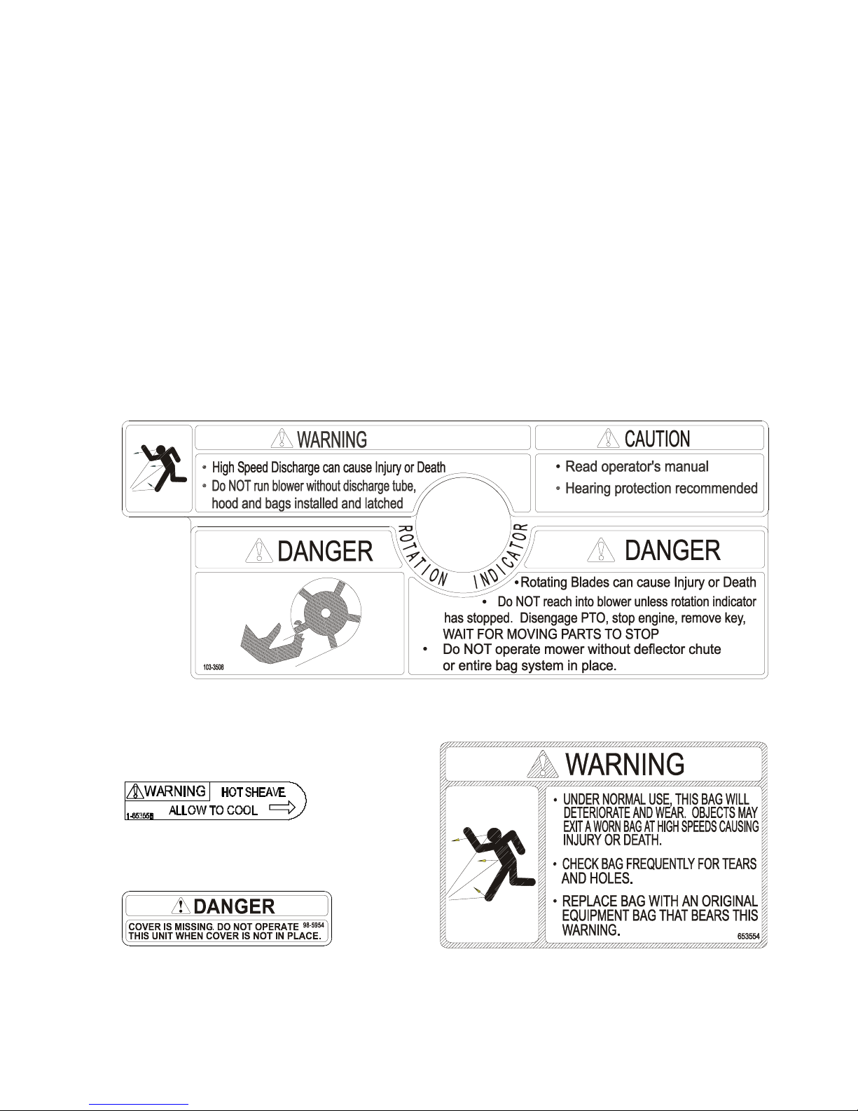
LZUV52 Only
PART NO. 103-3508
LOCATION: Top of Blower
PART NO. 1-653558
LOCATION: Top of Idler Arm
PART NO. 98-5954
LOCATION: Under Blower Cover
PART NO. 1-653554
LOCATION: Rear of Bags
7
Page 8
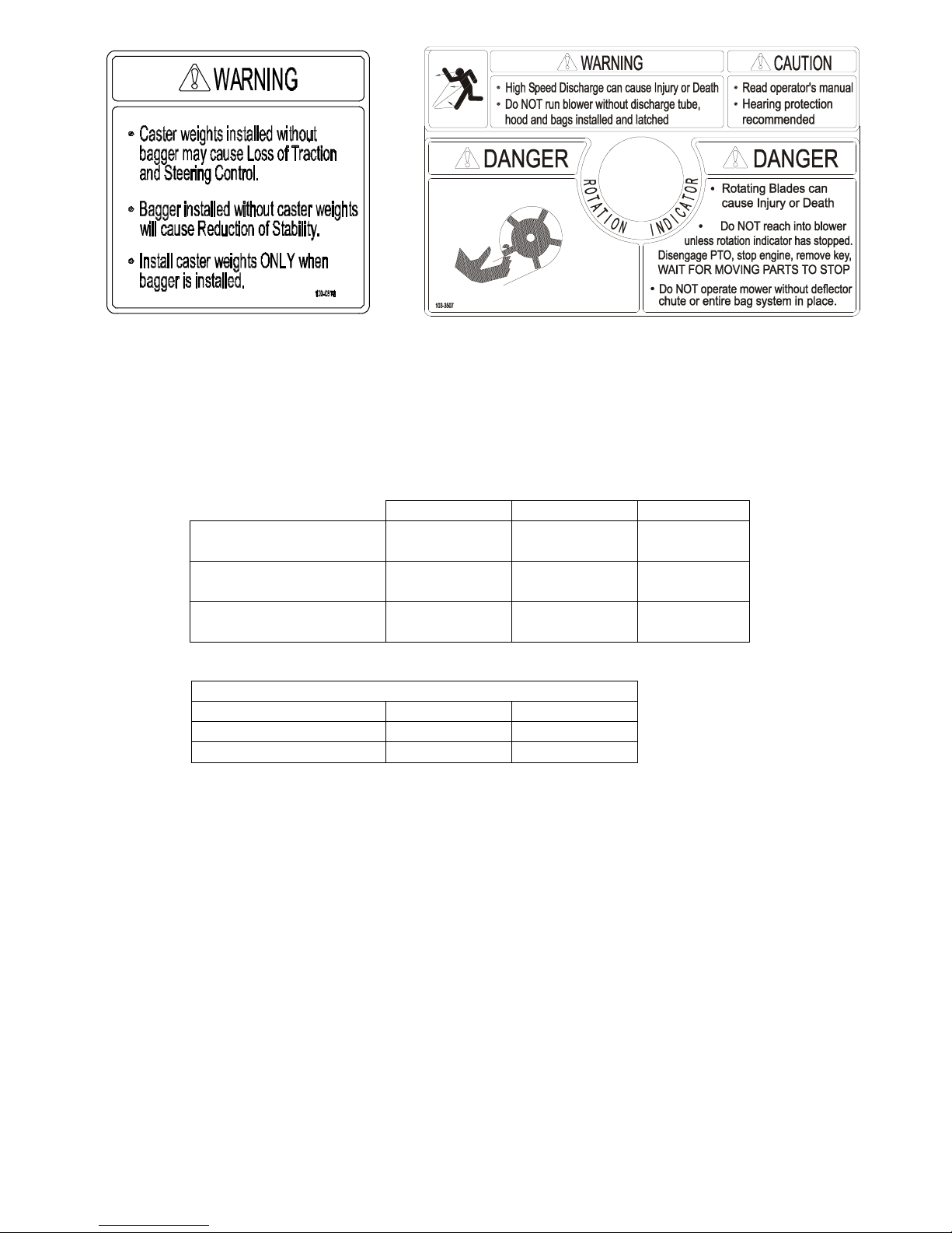
p
PART NO. 103-0878
LOCATION: Top of Weights
2. SPECIFICATIONS
2.1 DIMENSIONS
2.1.1 Overall unit length w/ Ultra Vac
Lazer Z - Air Cooled 105.70"
Lazer Z - Liquid Cooled 106.00"
Lazer Z XP 107.90"
2.1.2 Overall unit width w/ Ultra Vac
Lazer Z and Lazer Z XP
52" Deck 66.85" (169.8 cm)
60" Deck 74.44" (189.1 cm)
72" Deck 86.49" (219.7 cm)
LZUV60 & LZUV72 Only
PART NO. 103-3507
LOCATION: To
of Blower
52" Deck 60" Deck 72" Deck
(268.5 cm)
(269.1 cm)
106.65"
(270.9 cm)
106.90"
(271.5 cm)
110.75"
(281.3 cm)
111.00"
(281.9 cm)
112.00"
(274.1 cm)
(284.5 cm)
2.2 BAGGING SYSTEM
2.2.1 Lazer Z and Lazer Z XP – 52” Deck – 220 lbs. (100 kg) includes weight kit
2.2.2 Collections bins: Commercial grade, cloth mesh bags with reinforced bottoms.
Capacity: Lazer Z 52” - 8 bushels (2 bags and hood)
2.2.3 Dump Mechanism: Manual lift off
2.2.4 Blower tube: fixed, abrasion resistant molded polyethylene
2.2.5 Impeller: 5-bladed, 0.25” thick abrasion resistant steel, with vertical axis.
2.2.6 Impeller bearings: 1” (2.54 cm) sealed “non-greaseable bearings”
60” Deck – 290 lbs. (132 kg) includes weight kit
72” Deck – 237 lbs. (108 kg) includes weight kit
All 60 and 72” decks – 13.4 bushels (3 bags and hood)
8
Page 9

2.3 MODEL NUMBER:
LZUV52 – Fits Lazer Z with 52” deck
LZUV60 – Fits Lazer Z and Lazer Z XP with 60” deck
LZUV72 – Fits Lazer Z and Lazer Z XP with 72” deck
2.4 COMPLETING KITS
NEWER UNITS
UNIT SERIAL NUMBER DESCRIPTION REQ'D TO MOUNT ULTRA VAC
Lazer Z 52 352,000 & above LZ w/ 524 Deck, 3/4" spindle
nut (1 1/4 Hex)
Lazer Z 60 352,000 & above LZ w/ 604 Deck, 3/4" spindle
nut (1 1/4 Hex)
Lazer Z XP 60 352,000 & above XP w/ 604 Deck, 3/4" spindle
nut (1 1/4 Hex)
Lazer Z 72 352,000 & above LZ w/ 724 Deck, 3/4" spindle
nut (1 1/4 Hex)
Lazer Z XP 72 352,000 & above XP w/ 724 Deck, 3/4" spindle
nut (1 1/4 Hex)
103-2997 Drive Kit
103-2973 Drive Kit
103-2976 Drive Kit
103-2974 Drive Kit
103-2977 Drive Kit
103-1076 Drive Kit &
OR
103-2797 Sheave
103-0466 Drive Kit &
OR
103-2972 Sheave
103-1112 Drive Kit &
OR
103-2792 Sheave
103-0903 Drive Kit &
OR
103-2796 Sheave
103-1113 Drive Kit &
OR
103-2796 Sheave
OLDER UNITS
UNIT SERIAL NUMBER DESCRIPTION REQ'D TO MOUNT ULTRA VAC
Lazer Z 52 159,999 & Below LZ w/ 523 Deck, Greasable
Spindles
Lazer Z 52 160,000 to 259,999 LZ w/ 523 Deck 103-2997 Drive Kit
Lazer Z 52 260,000 to 351,999 LZ w/ 524 Deck, 5/8" spindle
nut (15/16 Hex)
Lazer Z 60 159,999 & Below LZ w/ 603 Deck, Greasable
Spindles
Lazer Z 60 160,000 to 189,999 LZ w/ 603 Deck 103-2973 Drive Kit
Lazer Z 60 190,000 to 259,999 LZ w/ 604 Deck, stiffening
rings on bottom
Lazer Z 60 260,000 to 351,999 LZ w/ 604 Deck, stiffening
rings on top, 5/8" spindle nut
(15/16 Hex)
Lazer Z XP 60 351,999 & Below XP w/ 604 Deck, 5/8" spindle
nut (15/16 Hex)
Lazer Z 72 259,999 & Below LZ w/ early 724 Deck, w/o
accessory mounting tube
Lazer Z 72 260,000 to 351,999 LZ w/ 724 Deck, w/ accessory
mounting tube, 5/8" spindle
nut (15/16 Hex)
Lazer Z XP 72 351,999 & Below XP w/ 724 Deck, 5/8" spindle
nut (15/16 Hex)
103-2997 Drive Kit
103-1369 Chute Kit
103-2547 Housing Kit
103-2998 Spindle Kit
103-1369 Chute Kit
103-2998 Spindle Kit
103-2997 Drive Kit
103-2999 Spindle Kit
103-2973 Drive Kit
103-2547 Housing Kit
103-2998 Spindle Kit
103-2998 Spindle Kit
103-2973 Drive Kit
103-3140 Spindle Kit
103-2973 Drive Kit
103-2999 Spindle Kit
103-2976 Drive Kit
103-2999 Spindle Kit
103-2974 Drive kit
103-2999 Spindle Kit
103-0583 Accy Tube
Kit
103-2974 Drive Kit
103-2999 Spindle Kit
103-2977 Drive Kit
103-2999 Spindle Kit
103-1079 Drive Kit &
OR
103-1369 Chute Kit
103-1076 Drive Kit &
OR
103-1369 Chute Kit
103-1076 Drive Kit
OR
103-0466 Drive Kit
OR
103-0466 Drive Kit
OR
103-0466 Drive Kit
OR
103-0466 Drive Kit
OR
103-1112 Drive Kit
OR
103-0903 Drive Kit &
OR
103-0583 Accy tube
kit
103-0903 Drive Kit
OR
103-1113 Drive Kit
OR
9
Page 10

3 ASSEMBLY INSTRUCTIONS – LAZER Z & LAZER Z XP
3.1 ASSEMBLY DIAGRAM
Ref . No. Description
1 Bag Assembly 2 3 3
2 Upper Tube 1 1 1
3 Lower Tube 1 1 1
4 #10-24 X .62 CRPH Screw 3 6 6
5 #10-24 Nyloc Nut 3 6 6
6 #10 Flat Washer 3 6 6
7 Hood Assembly 1 1 1
8 Blower Assembly 1 1 1
9 Bagger Mount Weldment 1 1 1
10 Belt Cover 1 1 1
11 Removable Weight 2 2 2
12 Jackshaft 1 1 1
13 Blower Drive Belt 1 1 1
14 Frame Bracket RH 1 1
15 Frame Bracket LH 1 1
16 Frame Bracket XP 2
17 XP Mount Spacer 2
18 Mount Pin Weldment 1 1
19 Clevis Pin 4 4 4
20 Hair Pin (large) 4 4 4
21 Chute Pivot Pin 1 1 1
22 Hair Pin (small) 1 1 1
23 3/8-16 x 1.00 Hex Screw 8 8 10
24 3/8 Whizlock Nut 8 11 13
25 3/8 Spring Disk Washer 12 12 14
26 Filler Plate (small) 1
27 Belt Shield Stud 1 1
28 3/8-16 x .75 Hex Screw 3 3
29 Belt Cover Spacer 1
30 7/16 Spring Disk Washer 2
31 Washer – ¼ thick 2 2 – 60 only
32 3/8-16x3.25 Tap Bolt 2 2 – 60 only
33 Weight Bracket 2 2 2
34 3/8-16 Square Head Bolt 4 4 4
35 Weight Plate 4 4 4
36 5/16-18 x 1.50 Hex Screw 4 4 4
37 5/16 Flat Washer 4 4 4
38 5/16-18 Whizlock nut 6 4 4
39 Belt Cover Support 2
40 Knob 1
41 5/16-18 x .75 Hex Screw 2
42 Plug 1 1 1
Qty
(52 LZ)
Qty
(60 & 72 LZ)
Qty
(60 & 72 XP)
10
Page 11
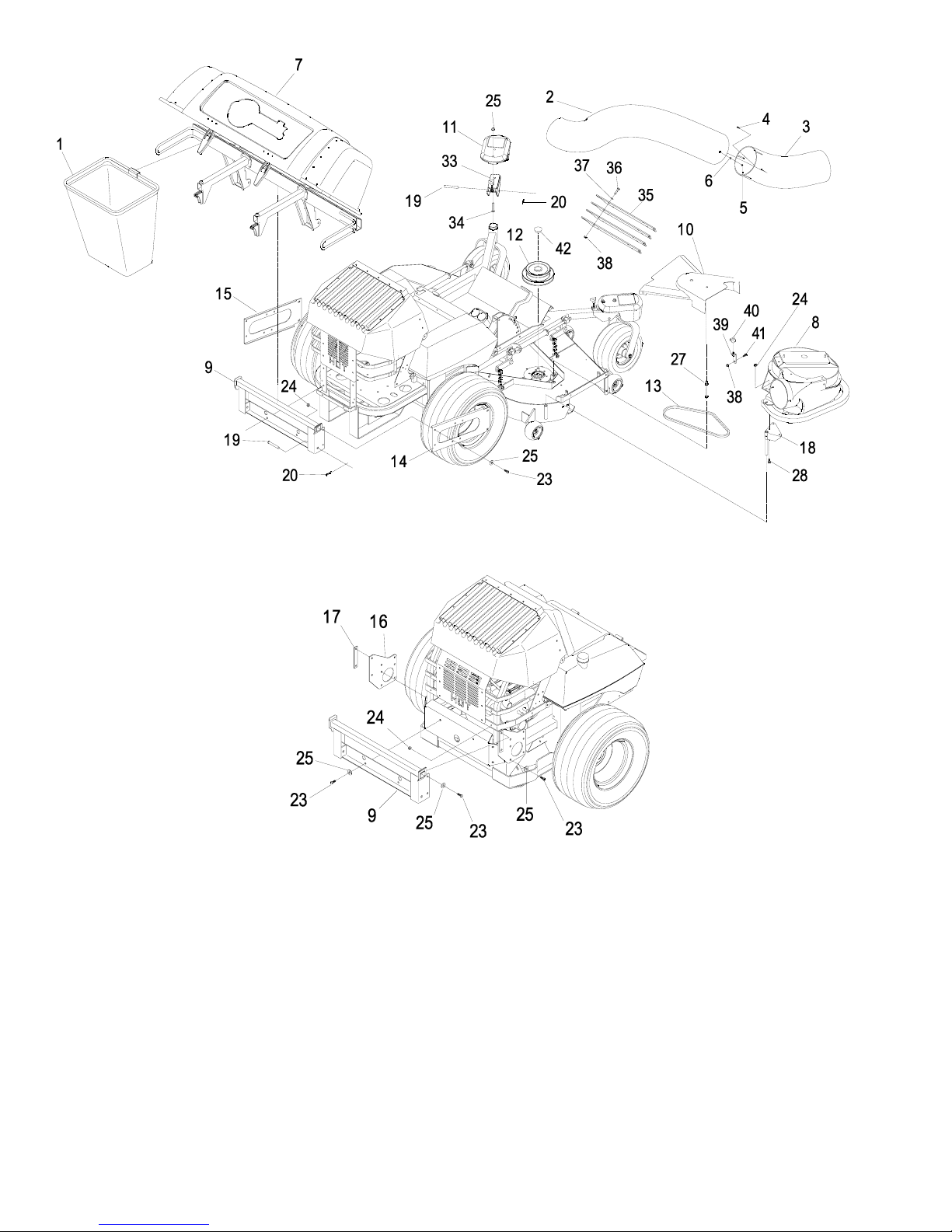
LAZER Z ASSEMBLY DIAGRAM
LAZER Z XP ASSEMBLY DIAGRAM
Items 21,22,26, 29, 30, 31 and 32 not shown. See figure 1 for installation of 31 and 32. See
figure 5 for installation of 29 and 30. See figure 9 for installation of 21 and 22.
• 52” Lazer Z units with serial numbers below 260,000 require the use of adapter kit 103-
1369. Follow the instructions included in the kit when noted in the following steps.
• 72” units below serial number 260,000 require the deck to be modified by adding the
accessory mounting tube. Exmark kit 103-0583 contains the parts and templates to do
this.
11
Page 12
3.2 INSTALL THE HOOD ASSEMBLY AND BAGS
Lazer Z units only (Lazer Z XP units skip to step 6)
1. When installing the Ultra Vac onto a liquid cooled Lazer Z, the rear bumper plate must be
removed. Remove rear bumper plate. Use two of the original bolts, washers and whizlock
nuts to attach the lower side bumper bars to the vertical “HOT” engine guard shield.
2. Remove the lower two bolts holding the clutch guard plate (“HOT” engine guard on liquid
cooled units) to the rear frame of the Lazer Z unit. Units with serial numbers below
160,000 will require disassembly of the clutch strap spacers to remove these bolts.
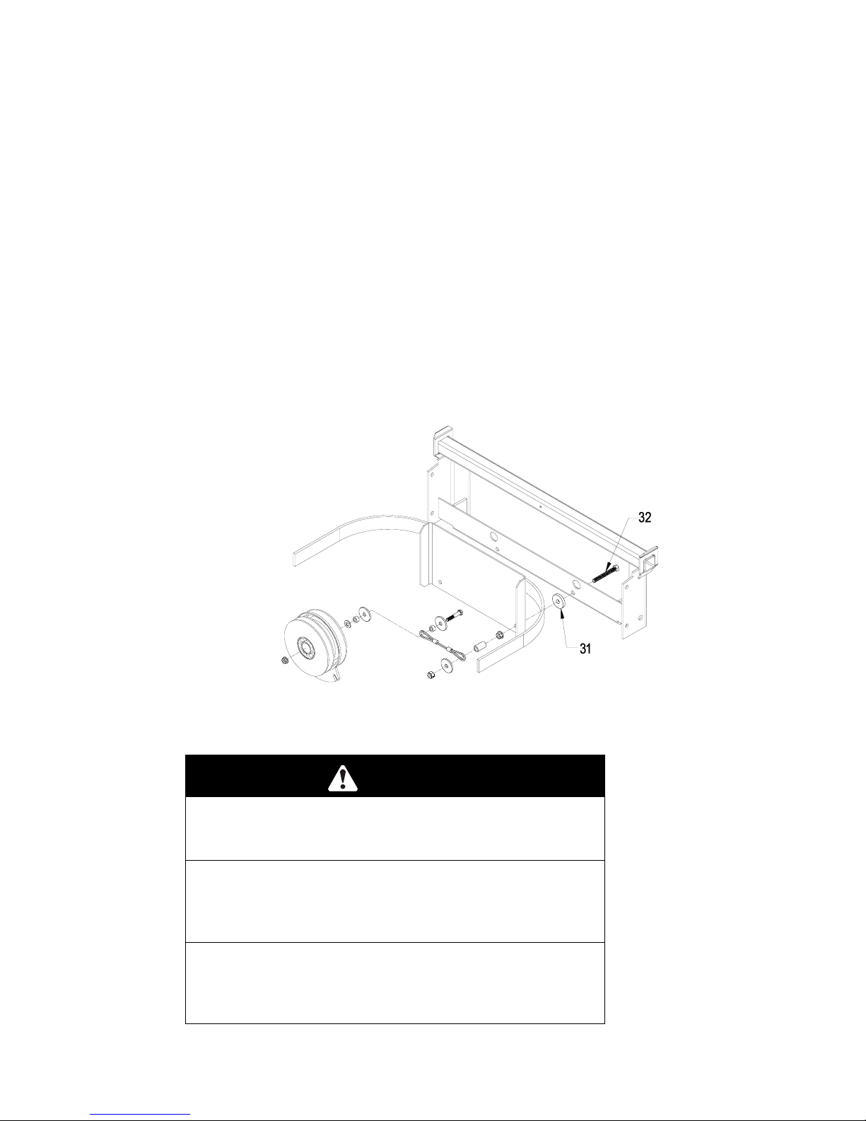
3. On units with serial numbers above 190,000 install the mount weldment (Item 9) loosely to
the rear of the machine using the two bolts and nuts removed in step 2.
For units with serial numbers below 190,000, install washers (Item 31) between the bagger
mount weldment and clutch guard when installing the bagger mount weldment. This will
provide for proper alignment of the mount holes with the holes in the side plates (see figure
1).
For units with serial numbers below 160,000, remove the two tap bolts that tie the clutch
straps to the clutch guard and replace with new tap bolts (Item 32). These units also require
the use of the washers (Item 31) between the bagger mount weldment and the clutch guard.
These parts should be installed when the bagger mount weldment is installed on the rear of
the unit (see figure 1).
4. Jack the rear of the unit up and safely support it on jack stands. Remove the rear wheels.
POTENTIAL HAZARD
♦ Relying solely on mechanical or hydraulic jacks to
support the mower could be dangerous.
WHAT CAN HAPPEN
♦ The mechanical or hydraulic jacks may not be enough
support or may malfunction allowing the unit to fall,
which could cause injury.
HOW TO AVOID THE HAZARD
♦ DO NOT rely solely on mechanical or hydraulic jacks
for support. Use adequate jack stands or equivalent
support.
FIGURE 1
CAUTION
12
Page 13

5. Install the side plates (Items 14 and 15) loosely to the mount weldment and the wheel
channels of the Lazer Z frame. The flanges on the side plates should face in towards the
unit to provide the maximum tire clearance. Use the 3/8-16 x 1.00 bolts (Item 23), 3/8
spring disk washers (Item 25) and 3/8-16 whizlock nuts (Item 24). Make sure that the
raised portion of the spring disk washer faces the head of the bolt. On 52 and 60 inch
units, the lower bolt on the wheel channel is best installed by positioning the nut behind the
hole using a deep socket and turning the bolt through the hole into the nut.
Lazer Z XP units only (Lazer Z units continue at step 8)
6. Install mount weldment (Item 9) loosely to the rear bumper using the two holes provided.
Use the 3/8-16 x 1.00 bolts (Item 23), 3/8 spring disk washers (Item 25) and 3/8-16
whizlock nuts (Item 24).
7. Install the side plates (Item 16) and spacers (Item 17) loosely to the mount weldment and
the mounting pads on the Lazer Z XP frame. Use the 3/8-16 x 1.00 bolts (Item 23), 3/8
spring disk washers (Item 25) and 3/8-16 whizlock nuts (Item 24). Make sure that the
raised portion of the spring disk washer faces the head of the bolt.
All Units
8. Tighten all the hardware, starting with the bolts that hold the mount weldment to the rear of
the unit and working forward.
9. On Lazer Z units, reinstall the rear wheels and lower the unit from the jack stands.
10. Apply a light coat of grease to the front and rear of the upper tube of the mount weldment.
Install the hood assembly (Item 7) onto the mount by slipping the hook portion over the top
mounting tube of the mount weldment. Secure the assembly to the mount using the clevis
pins (Item 19) and hairpins (Item 20).
11. Install the bag assemblies (Item 1) by inserting the hook portion into the slots in the cross
bar of the hood assembly.
3.3 INSTALL BLOWER ASSEMBLY
1. Lower the deck fully. Remove the right hand belt cover. Remove the belt cover mounting
stud that protrudes from the deck.
2. Remove the deck drive belt from around the right hand spindle sheave.
3. Support the right mower blade and shaft so that it will not fall out of the deck when the right
sheave nut is removed.
4. Remove the right sheave nut, spring disk washer, and sheave from the spindle shaft.
NOTE: On units with wrench flats on the spindle just above the blade use a 1-inch
wrench on the flat sides of the spindle shaft to prevent the spindle from turning. On
units that do not have a wrench flat, block the blade rotation with a block of wood
between the blade and baffles as indicated in the blade service section of the Lazer
operator’s manual. Do not use the blade bolt to prevent rotation.
5. Some older units may require the replacement of the spindle shaft, depending on the drive
kit that is used. (Ref section 2.4). On those units, remove the spindle shaft / blade
assembly from the mower. Transfer the blade from the original shaft to the new spindle
shaft and reinstall the assembly onto the mower.
6. Apply a light coat of grease to the top portion of the spindle shaft where the sheave
mounts.
7. Install the double sheave (Item 12) onto the right spindle shaft. Install the spring disk
washer and nut. Make sure that the spring disk washer cone is installed towards nut
(see figure 2). Torque the sheave nut to:
5/8 - 11 nut (15/16 Hex) - 75-80 ft. lbs.
3/4 -16 nut (1 ¼ Hex) – 140-145 ft. lbs.
13
Page 14

NOTE: On units with wrench flats on the spindle just above the blade use a 1-inch
wrench on the flat sides of the spindle shaft to prevent the spindle from turning. On
units that do not have a wrench flat, block the blade rotation with a block of wood
between the blade and baffles as indicated in the blade service section of the Lazer Z
operator’s manual. Do not use the blade bolt to prevent rotation. Check blade bolt
torque after completing this installation (115 – 120 ft. lbs.).
FIGURE 2
8. Re-install the deck drive belt in the lower groove of the double sheave. Install the
plug (Item 24) into the bore of the double sheave.
9. Remove the discharge chute from the deck. Discard the mounting hardware, but
save the discharge chute for use during side discharge operation. The chute pivot
pin (Item 21) and hairpin (Item 22) may be stored in the pivot holes on the discharge
chute during bagging operation.
52 inch units only (60 and 72 inch units skip to step 17)
10. Remove the belt guide on the blower (see figure 3)
11. Install the belt (Item 13) included in the completing kit onto the blower assembly as shown.
12. Reinstall the belt guide removed in step 9.
13. If the Ultra Vac is being installed on a Lazer Z with a serial number less than 260,000, it is
recommended to replace the steel blocker plate mounted across the bottom of the blower
FIGURE 3
BELT ROUTING
14
Page 15

with the small filler plate included in the completing kit (Item 26). Use the hardware that
was removed when removing the large blocker plate (see figure 4). Failure to install a
blocker plate will create a thrown object hazard that could injure or kill bystanders,
or cause property damage. This modification should not be done if the Ultra Vac blower
will be mounted on a Lazer Z with a serial number of 260,000 or higher.
FIGURE 4
LAZER Z 52 UNITS WITH SERIAL NUMBERS
LESS THAN 260,000 ONLY
14. The front right deck stiffener must be trimmed for belt clearance on 52” Lazer Z units with
serial numbers less than 220,000. Measure and mark the deck stiffener (see figure 5).
Trim off the indicated portion of the stiffener. Touch up the trimmed area with Exmark red
touchup paint – P/N 1-850337.
FIGURE 5
LAZER Z 52 UNITS WITH SERIAL NUMBERS
LESS THAN 220,000 ONLY
15
Page 16

14. Using the knob that was removed with the original belt cover stud and the knob included
with the completing kit (Item 40), mount the two belt cover supports (Item 39) to the plastic
belt cover (Item 10). Position the belt cover on the mower deck. The lower ends of the belt
cover supports should rest on the outside of the deck stiffeners. Mark the location of the
belt cover support holes on the deck stiffeners. Remove the belt cover. Center punch and
drill 3/8” holes.
15. Remove the belt cover supports from the belt cover and mount them to the deck using the
5/16-18 x .75 screws (Item 41) and whizlock nuts (Item 38).
16. Units with serial numbers below 260,000 will require modifications to the discharge chute
tabs per the instructions in adapter kit 103-1369. Follow the instructions included in the kit
before proceeding with the blower installation.
60 and 72 inch units only (52 inch units continue at step 21)
17. Install the belt cover mounting stud (Item 27) included in the Ultra Vac completing kit.
For 60 inch units only, install the spacer (Item 29), two 7/16 spring disk washers
(Item 30) and the plastic knob (see figure 6). The knob does not need to be tightened
against the washers at this time.
FIGURE 6
18. Install the mounting pin weldment (Item 18) to the blower assembly using the 3/8-16 x .75
bolts (Item 28) and whizlock nuts (Item 24). Maximum deck clearance will be provided if
the bolts are installed from below the mounting pin. The mount pin can be installed in two
positions. For 60 inch decks the pin should be installed as far away from the bumper end
as possible. For 72 inch decks that pin should be installed close to the bumper end (see
figure 7).
FIGURE 7
16
Page 17

19. Install the belt (Item 13) onto the blower by working it around the impeller sheave.
20. 72” units below serial number 260,000 will require the deck to be modified by adding the
accessory mounting tube. Exmark kit 103-0583 contains the parts and templates required.
Follow the instructions in this kit. These decks will also require drilling the hole at the front
upper corner of the discharge opening to ½ inch diameter (see figure 8). Touch up with red
paint Exmark P/N 850337.
FIGURE 8
72 UNITS WITH SERIAL NUMBERS
LESS THAN 260,000 ONLY
All units
21. Mount the blower on the deck by sliding the mounting pin into the tube at the rear right
corner of the deck. Swing the blower closed. Adjust the position of the front pin to engage
the slot in the front of the deck. Use the latch to lock the blower in this position. Adjust the
tension on the latch to hold the blower up to the deck, yet allow for release by hand.
22. Pull the spring loaded idler back and slip the belt over the top sheave on the deck spindle.
23. Install the plastic belt cover (Item 10). On 60” units the outside end of the cover is slotted
and can slip between the two washers assembled in step 17. The plastic knob does not
need to be removed. On 72” and 52” units the cover has a hole, and the plastic knob must
be installed after the cover has been positioned. The original belt cover stud must be
removed on 52” units.
3.4 ASSEMBLE THE TUBES
1. Remove the six screws, nuts, and washers (Items 4,5,and 6) from the lower tube (Item 3)
and slide the lower and upper tube (Item 2) together. The arrow on the upper tube should
align with the dimple on the lower tube. On 60 and 72 inch units there are two sets of holes
on the lower tube. The first set reached is for use with Lazer XP units. The second set
reached is for Lazer Z units. Align the arrow on the upper tube with the dimple on the lower
tube and slide them together until the proper set of holes is reached.
2. Fasten the upper and lower tubes together using three of the hardware sets removed from
the lower tube in step 14. The heads of the screws must be inside the tube to prevent
accumulation of grass inside the tube. The washer and the nut should be installed on the
outside of the tube. On Lazer XP units, use the remaining three hardware sets to plug the
exposed holes in the lower tube. On Lazer Z units, discard the remaining hardware sets.
3. Slip the upper end of the tube assembly into the hood opening. Slide the lower end of the
tube assembly over the blower outlet and align the notch with the tube latch. Latch the
tube to the blower.
17
Page 18

3.5 INSTALL THE WEIGHT PLATES
1. The four weight plates (Item 35) must be installed under the front panel of the floor pan.
These weights give proper balance to the machine when the removable portions of the
bagger are removed.
2. Locate the position of the mounting holes. On some machines the hole positions are
indicated by tool marks on the floor pan. Most machines will require clamping a weight
plate to the front of the floor pan (see figure 9). The ears on the weight plate should be
towards the bottom (upside down from the actual mounted position). Align the bottom edge
of the weight plate with the bottom edge of the floor pan front panel. Center the weight
plate side to side. Mark the position of all four holes using a center punch.
3. Drill 3/8 inch holes at the points marked.
4. Open the floor pan and install the four weight plates behind the front panel using the 5/16-
18 x 1.50 screws, 5/16 washers and 5/16-18 whizlock nuts (Items 36, 37, and 38). The
weight plates will only fit with the ears located near the bend in the floor pan. The decal on
the outside of the floor pan will still be visible with the weight plates mounted.
FIGURE 9
FLOORPAN WEIGHT INSTALLATION
3.6 INSTALL THE REMOVABLE WEIGHTS
Note: The removable weights are heavy. Use
care when lifting them. Make sure that you can
hold them securely before lifting them. Use
caution when positioning your hands so that you
do not set them down on your hands or fingers.
1. Assemble the weight brackets (Item 33) to the
removable weights (Item 11) using the 3/8-16
square head bolts (Item 34) and 3/8 whizlock nuts
(Item 25).
2. Install the removable weight assemblies over the
caster arms. On 52 and 60 inch Lazer Z machines
one weight has a wide mounting bracket and one
has a narrow bracket. They will only fit the
machine one way. Weights for the 60 Lazer XP
and all 72s are interchangeable left and right.
3. Install a clevis pin (Item 19) and hairpin (Item 20)
on each caster weight to retain them.
FIGURE 10
REMOVABLE WEGHT
INSTALLATION
18
Page 19

4. Tighten knob on weight assembly until the weight is
clamped securely to the caster arm.
3.7 RUN IN – 52” UNITS ONLY
1. Follow the operation instructions in Section 5 to run the unit. Run the unit with the blades
and blower engaged for 2 minutes. Disengage the blades, stop engine and wait for all
moving parts to stop. Remove key.
2. Remove the belt cover and check to make sure that the belt is riding near the center of the
flat idler on the idler arm. If the belt is not riding near the center of the idler, remove the
blower, and bend the idler arm slightly. Reinstall the blower and belt cover and perform
steps 1 and 2 again to verify belt position.
4. OPERATION:
Although hazard control and accident prevention are partially dependent upon the design
and configuration of the equipment, these factors are also dependent upon the awareness,
concern, prudence, and proper training of the personnel involved in the operation, transport,
maintenance, and storage of the equipment. It is essential that all Operator Safety
Mechanisms be connected and in operating condition prior to use for mowing. Refer to the
Operator’s Manual for the mower for additional hazard control and accident prevention
information.
WARNING
POTENTIAL HAZARD
♦ An uncovered discharge opening will allow objects to
be thrown in operator’s or bystander’s direction.
Also, contact with blade could occur.
WHAT CAN HAPPEN
♦ Thrown objects or blade contact can cause serious
injury or kill you or bystanders.
HOW TO AVOID THE HAZARD
♦ Never operate mower unless discharge chute or
entire grass collection system is installed.
DANGER
POTENTIAL HAZARD
♦ There are rotating blades in the blower and under
the mower deck.
WHAT CAN HAPPEN
♦ Blade contact can cause serious operator or
bystander injury or even death.
HOW TO AVOID THE HAZARD
♦ Keep hands and feet out of blower openings and out
from under the mower or mower deck.
♦ Shut off the deck drive, stop the engine, and wait for
all moving parts to stop before clearing obstructions.
4.1 PRE-START
Note: When mowing in areas with sandy soil, use low lift blades on the cutting deck
and higher cutting heights to minimize wear on the blower components.
19
Page 20

1. Read the operator’s manual for your mower and familiarize yourself with all controls before
operating the machine. Make sure that you understand the controls, their locations, their
functions, and their safety requirements.
2. Ensure the blower, belt cover, bags, tube and hood are in good condition, properly
attached, and latched.
4.2 MOWING
1. The Ultra Vac blower operates when deck drive is engaged. Be sure that all persons are
clear of the mower deck and blower before engaging the cutting blades. Set the throttle
to “midway” position. Pull outward on the PTO switch to the “ROTATE” position.
Accelerate to full throttle to begin mowing.
2. To disengage the deck drive and blower, set the throttle to “midway” position. Push in on
the PTO switch to the “STOP” position to stop the cutting blades and blower. The cutting
blades will require a slightly longer amount of time to come to a complete stop when the
blower is installed on the deck.
3. To remove the bags, shut off deck drive, stop the engine and wait for all moving parts to
stop. Open the hood and remove the bags by lifting up on the rear of the bag, then
unhooking the front clip. Empty bags by inverting them.
4. Reinstall bags, close and latch the hood before continuing mowing.
4.3 BAGGER REMOVAL FOR SIDE DISCHARGE:
1. Shut off the deck drive, stop engine and wait for all moving parts to stop. Remove key.
2. Remove the discharge tube by releasing the latch at the blower. Slide the tube off the
blower outlet and remove the upper end from the hood.
3. Remove the Belt cover by loosening the knobs. For 60” units the outboard knob does not
need to be removed completely to remove the belt cover.
CAUTION
POTENTIAL HAZARD
♦ The deck sheave will become very hot
WHAT CAN HAPPEN
♦ Touching a hot deck sheave can cause severe burns.
HOW TO AVOID THE HAZARD
♦ Allow the deck sheave to cool completely before
removing the belt.
4. Pull the idler release handle and remove the belt from the upper groove of the deck
sheave.
5. Unlatch the front end of the blower. Pivot the blower back and lift it off the deck.
6. Install the discharge chute using the chute pivot pin and hairpin (see figure 11).
21
22
FIGURE 11
DISCHARGE CHUTE INSTALLATION
20
Page 21

7. Re-install the plastic belt cover and tighten the knobs.
8. Remove the hair pins and clevis pins holding the hood assembly to the mount weldment.
9. Lift the bag and hood assembly off the mount.
10. The removable weights must be removed from above the caster wheels. Loosen the
clamping knobs until the weight can be moved relative to the caster arm. Remove the
hairpins and clevis pins that hold the weights to the caster arms. Carefully lift the weights
off of the caster arms.
Note: The removable weights are heavy. Use care when lifting them. Make sure that
you can hold them securely before lifting them. Use caution when positioning
your hands so that you do not set them down on your hands or fingers.
Note: The portions of the Ultra Vac bagger that are not bolted to the mower are
designed to be installed or removed in their entirety. Do not operate the mower
with only a portion of the Ultra Vac installed.
CAUTION
POTENTIAL HAZARD
♦ Caster weights installed without bagger may cause
Loss of Traction and Steering control.
WHAT CAN HAPPEN
♦ Loss of control can result in an accident, which may
cause Death, Injury, or property damage.
HOW TO AVOID THE HAZARD
♦ Install caster weights ONLY when bagger is installed.
11. The machine can now be used for side discharge mowing.
4.4 TRANSPORTING
1. Transporting a Unit: Use a heavy-duty trailer or truck to transport the machine. Lock brake
and block wheels. Securely fasten the machine to the trailer or truck with straps, chains,
cable, or ropes. Be sure that the trailer or truck has all necessary lighting and marking as
required by law. Secure a trailer with a safety chain.
CAUTION
POTENTIAL HAZARD
♦ This unit does not have proper turn signals, lights, reflective
markings, or a slow moving vehicle emblem. These items
are required to drive on a public street or roadway.
WHAT CAN HAPPEN
♦ Driving on a street or roadway without such equipment is
dangerous and can lead to accidents causing personal injury.
♦ Driving on a street or roadway without such equipment may
also be a violation of State laws and the operator may be
subject to traffic tickets and/or fines.
HOW TO AVOID THE HAZARD
♦ Do not drive a unit on a public street or roadway.
21
Page 22

WARNING
POTENTIAL HAZARD
♦ Loading a unit on a trailer or truck increases the possibility of
backward tip-over.
WHAT CAN HAPPEN
♦ Backward tip-over of the unit could cause serious injury or
death.
HOW TO AVOID THE HAZARD
♦ Use extreme caution when operating a unit on a ramp.
♦ Use only a single, full width ramp; DO NOT use individual
ramps for each side of the unit.
♦ If individual ramps must be used, use enough ramps to create
an unbroken ramp surface wider than the unit.
♦ DO NOT exceed a 15° angle between ramp and ground or
between ramp and trailer or truck.
♦ Avoid sudden acceleration while driving unit up a ramp to
avoid tipping backward.
♦ Avoid sudden deceleration while backing unit down a ramp to
avoid tipping backward.
2. Loading a Unit: Empty grass bags before attempting to load unit on trailer or truck.
Use extreme caution when loading units on trailers or trucks. One full width ramp that is
wide enough to extend beyond the rear tires is required instead of individual ramps for
each side of the unit. The lower rear section of the tractor frame extends back between
the rear wheels and serves as a stop for tipping backward. Having a full width ramp
provides a surface for the frame members to contact if the unit starts to tip backward. If it
is not possible to use one full width ramp, use enough individual ramps to simulate a full
width continuous ramp.
Ramp should be long enough so that the angles between the ramp and the ground and the
ramp and the trailer or truck do not exceed 15°. A steeper angle may cause mower deck
components to get caught as the unit moves from ramp to trailer or truck. Steeper angles
may also cause the unit to tip backward. If loading on or near a slope, position the trailer or
truck so it is on the down side of the slope and the ramp extends up the slope. This will
minimize the ramp angle. The trailer or truck should be as level as possible.
DO NOT attempt to turn the unit while on the ramp, you may lose control and drive off the
side.
Avoid sudden acceleration when driving up a ramp and sudden deceleration when backing
down a ramp. Both maneuvers can cause the unit to tip backward.
5. MAINTENANCE:
5.1 PERIODIC MAINTENANCE
IMPORTANT: Before conducting any maintenance, shut off deck drive, stop engine and
wait for all moving parts to stop. Remove spark plug wire(s) or remove key.
5.1.1 Blower Housing/Impeller Service Interval: Daily.
Inspect for wear or damage daily. Replace or repair worn parts as needed.
Note: When mowing in areas with sandy soil, use low lift blades on the cutting
deck and higher cutting heights to minimize wear on the blower components.
22
Page 23

5.1.2 Idler Bushings: Service Interval: 25 Hours.
Lubricate with 1-2 pumps of SAE No. 2 multi-purpose grease.
5.1.3 Bags: Service Interval: Daily
Inspect the bags for wear, tears, or damage.
.
WARNING
POTENTIAL HAZARD
♦ Under normal use the bag will deteriorate and wear.
Objects could exit a worn bag at high speeds.
WHAT CAN HAPPEN
♦ Thrown objects can cause serious injury or kill you or
bystanders.
HOW TO AVOID THE HAZARD
♦ Check bag frequently for tears and holes. Replace
worn bag.
5.1.4 Belts. Service Interval: 50 Hours.
a) For 52” units only - Inspect the belt position on the idler arm.
The idler arm may become bent during use or transport. A bent idler arm could
cause the belt to jump off of the idler and be damaged.
1) Make sure the belt cover is installed and run the blower for one to two minutes.
2) Shut off the deck drive, stop engine and wait for all moving parts to stop.
Remove key. Remove the belt cover and check to make sure that the belt is
riding near the center of the flat idler on the idler arm.
3) If the belt is not riding near the center of the idler, remove the blower, and bend
the idler arm slightly.
4) Reinstall the blower and belt cover and repeat steps 1-3 until the belt is
positioned near the center of the idler.
b) All Units - Inspect the belt for damage or wear. Replace belt with one of the
following.
52” deck – PN 1-653438
60” deck – PN 103-0866
72” deck – PN 103-0867
5.1.5 Clean muffler and rear frame area:
Service Interval: Daily
POTENTIAL HAZARD
♦ Operating engine parts, especially the muffler, become
extremely hot.
WHAT CAN HAPPEN
♦ Severe burns can occur on contact.
♦ Debris, such as leaves, grass, brush, etc. can catch fire.
HOW TO AVOID THE HAZARD
♦ Allow engine parts, especially the muffler, to cool before
touching.
♦ Remove accumulated debris from muffler and engine area.
♦ Install and maintain in working order a spark arrester before
using equipment on forest-covered, grass-covered, brushcovered unimproved land.
WARNING
23
Page 24

6. Tips and Troubleshooting
Your Exmark Ultra Vac has been designed to be the most productive bagging system on the
market. The following tips have been collected to help you get the most out of your Ultra Vac right
from the start.
6.1 When mowing in areas with sandy soil, use low lift blades on the cutting deck and higher
cutting heights to minimize wear on the blower components.
6.2 When mowing in wet conditions, such as just after a rain or in heavy dew, use low lift
blades on the cutting deck to minimize plugging of the blower.
6.3 When the bags get full, the sound of the blower will change and there will be slight
blowout from the front right corner of the deck. Emptying the bags at this point will
minimize the potential for the tube to plug.
6.4 If there is excessive blowout from the deck, check to make sure that the rear screen in
the hood is clear of grass build up. It is recommended that the screen and mesh
portions of the bags be cleaned regularly to maintain proper air flow. This is especially
important in wet conditions.
6.5 During dry conditions check engine air cleaners and clean cooling fins more frequently.
The Ultra Vac has been designed to minimize the impact of dust and debris on the
mower, but bagging can be a dirty environment.
6.6 During dry conditions, switching to a lower lift blade may reduce blowout without hurting
quality of cut.
6.7 Maintaining a ground speed that does not pull down the engine RPM will allow for the
highest productivity and best quality of cut. Bogging the engine RPM down by going too
fast will cause plugging and quality of cut issues.
6.8 When storing the Ultra Vac, it is recommended that any build up in the blower be
cleaned out. Dry grass build up may cause problems with the impeller when the unit is
put back into operation.
6.9 If the blower drive belt snaps or breaks frequently, check the alignment of the idler arm
per section 5. An arm that is bent out of position can cause the belt to jump off of the
idler and be cut by the sheaves.
6.10 If the idler pulley contacts the deck sheave, check the alignment of the idler arm per
section 5. Also check the mounting tube on the deck and the mounting pin on the
blower for bending or excessive wear. This condition is more likely to occur with smaller
deck sizes.
24
Page 25

7. PARTS LISTS
7.1 DECALS
Ref
Part No. Description Req'd.
No.
1 103-3508 Decal, Warning 52.……...1
2 1-653558 Decal, Hot Sheave……....1
3 1-653546 Decal, Exmark 52 ……… 1
103-0438 Decal, Exmark 60 & 72 .. 1
4 98-5954 Decal, Missing Cover…...1
5 1-653557 Decal, Ultra Vac………....1
6 103-0878 Decal, Caster Weights.... 3
7 103-3507 Decal, Warning 60 & 72.. 1
Qty.
25
Page 26

7.2 BLOWER ASSEMBLY – LAZER Z 52
26
Page 27

7.2 BLOWER ASSEMBLY – LAZER Z 52 (cont.)
Ref.
No.
Part No. Description Req'd.
Qty.
Ref.
No.
Part No. Description Req'd.
Qty.
1∇ 103-2875-03 Blower mount wldmt ………...1 31 1-303334 5/16 Spring disk washer........... 1
2 1-652351 Impeller wldmt .......................1 32 3229-11 1/4-20x.62 Carr. bolt RHSN …5
3 1-653346 Bearing, SPH. OD .................2 33 103-0126 Bushing,Locator ....................... 1
4 1-513013 Housing, flange .....................4 34 3257-32 5/8x3/16 #61 Woodruff key...... 1
5X 10³-1047 Sheave, blower......................1 35 103-3585 Cover, bearing (103-3586-03)
6 103-3592 Upper housing weldment with decal ................................. 1
(1-652345) with decals..........1 36 3296-29 5/16-18 nyloc nut ..................... 2
7 1-653331 Spring, idler ...........................1 37 3256-3 5/16x7/8 OD flat washer .......... 2
8 3290-357 3/8-16 whizlock nut................8 38 3274-18 5/16-18x1.25 Soc. Hd Screw. .. 1
9 323-7 3/8-16 x 1.25 screw ...............1 39
1-803075 #10-24x.75 CRTH Screw......... 8
10 323-11 3/8-16 x 2.25 screw ...............3 40 1-809112 #10-24 whizlock nut ................. 3
11 323-12 3/8-16 x 2.50 screw ...............2 41 1-803076 1/4-20x.75 CRTH Screw.......... 2
12 3256-4 Flat washer -.438x1.00x.083 .4 42 3274-107 3/8-16x1.75 Soc But Hd Screw 1
13 103-4171 Chute, blower ........................1 43 1-353050 Pin, Grass Catcher................... 1
14 1-353054 Latch, grass catcher..............1 44 1-806323 Roll Pin..................................... 1
15 3296-39 3/8-16 nyloc nut.....................1 45 1-653596-03 Plate, Blower Backing .............. 1
16 1-653322 Idler, inside ............................1 46 1-811006 Zerk, 1/8 – 28 straight .............. 1
17 103-0130 Bushing, idler pivot ................1 47 3256-24 3/8 Flat washer ........................ 1
18 1-653352-01 Bumper ..................................1 48 1-653443-03 Plate, Filler below S/N 260,000.1
19 103-2876 Idler Assy with bushings, 49 103-1042-03 Plate, blocker LZ 52 ……….…. 1
zerk, and decal ......................1 50 3217-6 5/16-18 nut ............................... 1
20 3230-18 5/16-18 x .62 carriage bolt ....6 51 103-1103 Idler, Flat .................................. 1
21 1-513208 Spring - disk ..........................1 52 3290-500 #10-24 x .62 CRPH Screw....... 5
22 3219-6 5/8-18 nut ..............................1 53 323-8 3/8 – 16 x 1.50 screw ............... 1
23 3220-5 1/2-20 Jam nut ......................1 54 1-653600 Bearing ..................................... 2
24 1-513435 Spring - disk ..........................1 55 1-653429 Latch Assy (Latch & Catch) ..... 2
25 1-653365 Spacer ...................................1 56 3296-2 #10-24 Nyloc Nut ..................... 3
26 1-653366 Hub ........................................1 57 3256-14 #10 Flat Washer....................... 9
27 32128-20 5-16-18 whizlock nut .............6 58 103-4176 Tube, lower LZ 52 .................... 1
28 3290-500 #10-24x.62 CRPH Screw ......4 59 103-0811 Tube, upper LZ 52” ................ 1
29
321-3 1/4-20x.62 Hex SCREW........8 103-1209 Blower Assy, LZ 52
30 32128-33 1/4-20 whizlock nut................15
(includes items 1-55)................ 1
Exmark red touch up spray paint - P/N 1-850337
Use grease on bore of sheave.
X
Includes items 43 and 44.
∇
27
Page 28

7.3 HOOD AND BAG ASSEMBLY – LAZER Z 52
28
Page 29

7.3 HOOD AND BAG ASSEMBLY – LAZER Z 52 (cont.)
Ref.
No.
Part No. Description Req'd.
Qty.
Ref.
No.
Part No. Description Req'd.
Qty.
1 1-653396 Hood .................................... 1 31 114974-03 Clamp ......................................1
2 1-653397-03 Stiffener, bagger top ............. 1 32 3230-1 5/16-18x.75 Carriage bolt .......2
3 103-0825-03 Hinge wldmt RH.................... 2 33 3296-29 5/16-18 nyloc nut.....................2
103-0826-03 Hinge wldmt LH .................... 2 34 103-0431 Cloth bag .................................1
4 114967 Screen................................... 1 35 1-653566 Bag handle..............................1
5 114439 3/16x.5 Pop rivet ................... 38 36 3229-1 1/4-20x.75 Carriage bolt .........2
6 1-803075 #10-24x.75 CRTH Screw...... 6 37 1-653036 Washer .344x1.75x.062 pltd ...2
7 3256-61 .216x.750x.049 Flat washer.. 14 38 3296-42 1/4-20 nyloc nut .......................2
8 3296-2 #10-24 nyloc nut ................... 10 39 1-653404 Catch .......................................1
9 1-653561 Seal, chute ............................ 1 40 3290-500 #10-24x.625 CRPH Screw......2
10 1-653598-03 Clamp, seal ........................... 1 41 1-809112 #10-24 whizlock nut ................2
11 103-1346 Seal....................................... 1 42 1-652414-03 Bag support wldmt ..................1
1-653400-03 Support, screen .................... 1 43 32128-33 1/4-20 whizlock nut .................1
12
13 1-653519 Mount, latch .......................... 1 44 1-523420 Bumper....................................1
14 1-653036 Washer .344x1.75x.062 pltd . 2 46 322-5 5/16-18x1 Screw 44”, 48” only 8
15 321-4 1/4-20x.75 Hex Head Screw. 6 322-9 5/16-18x1.75 Screw (LHP 52”only)8
16 32128-33 1/4-20 whizlock nut ............... 6 47X 1-654597 Hood assembly – service only 1
17 1-653403 Latch ..................................... 1 49 1-806005 Hair Pin....................................2
18 1-653535 Latch reinforcement .............. 1 50 32128-20 5/16-18 whizlck nut (LHP 52”only)4
19 321-11 1/4-20x2.0 Hex Head Screw. 1 52 103-0429-03 Bagger Mount Wldmt ..............1
21 3296-42 1/4-20 nyloc nut .................... 3 53 103-2972-03 Bracket Frame LH ...................1
22 321-6 1/4-20x1.00 Hex Head Screw 2 54 103-0399-03 Bracket Frame RH ..................1
23 103-1310-03 Bagger upright wldmt ............ 1 55 3290-357 3/8-16 Whizlock nut ................8
24 3256-2 Flat washer .312x.734x.065… 2 56 98-5975 Spring disk washer..................8
1-633545 Spacer..................................... 2
25
323-6 3/8-16-1.0 Screw ....................8
57
26 1-653544 Spring...................................... 2 58 283-69 Clevis Pin ................................2
27 322-3 5/16-18x.75 Hex Hd Screw.....2 59* 103-0435 Bag Assembly .........................1
28 1-653528-03 Plate, backing .........................1 60 3274-55 Screw, HSBH 5/16-18x.75 ......2
29 1-653529-03 Frame, bag.............................. 1 61 3250-27 Screw, PPH #10-24x.88..........4
30 114973-03 Hanger, bag ............................1
X Includes items 1,2,4,7,12,13,18 riveted together and Decal
* Includes items 29 through 38.
29
Page 30

7.4 BLOWER ASSEMBLY – LAZER Z 60 & 72 and LAZER Z XP 60 & 72
30
Page 31

7.4 BLOWER ASSEMBLY – LAZER Z 60 & 72 and LAZER Z XP 60 & 72 (cont.)
Ref.
No.
Part No. Description Req'd.
Qty.
Ref.
No.
Part No. Description Req'd.
Qty.
1 103-0454-03 Blower mount wldmt 60”&72”.1 32 103-3583 Cover, bearing (103-3584-03)
2 103-0455 Impeller wldmt .......................1 with decal ................................. 1
3 1-653346 Bearing, SPH. OD .................2 33 3296-29 5/16-18 nyloc nut ..................... 2
4 1-513013 Housing, flange .....................4 34 3256-3 5/16x7/8 OD flat washer .......... 2
5X 10³-0456 Sheave, blower......................1 35 3274-18 5/16-18x1.25 Soc. Hd Screw. .. 1
6 103-3593 Upper housing weldment 36 1-803075 #10-24x.75 CRTH Screw. ........ 3
(103-0457-03) with decals.....1 37 1-809112 #10-24 whizlock nut ................. 3
7 1-653331 Spring, idler ...........................1 38
1-803076 1/4-20x.75 CRTH Screw .......... 2
8 3290-357 3/8-16 whizlock nut................8 39 323-8 3/8 – 16 x 1.50 screw ............... 1
9 323-7 3/8-16 x 1.25 screw ...............1 40 103-2898 Latch, Rubber .......................... 2
10 323-11 3/8-16 x 2.25 screw ...............4 41 3217-6 5/16-18 nut............................... 1
11 3256-4 Flat washer -.438x1.00x.083 .4 42 103-0461-03 Plate, Blower Backing .............. 1
12 103-4169 Chute, blower ........................1 44 302-19 Zerk, 1/8 – 28 straight .............. 1
13 1-353054 Latch, grass catcher ..............1 45 103-0483 Idler .......................................... 1
14 3296-39 3/8-16 nyloc nut.....................1 46 1-653367 Hub, spacer.............................. 1
15 1-603044 Bushing, idler pivot ................1 47 1-653600 Bearing ..................................... 2
16 103-0458-01 Bumper ..................................1 48 32105-13 Screw, HH Washer #10-24x.75 .10
17 103-0448 Idler Assy with bushings 49 103-4170 Tube, lower .............................. 1
(103-0462-03) zerk, & decal ..1 50 103-0424 Tube, upper 60” ..................... 1
18 3230-18 5/16-18 x .62 carriage bolt ....6 103-0425 Tube, upper 72” ..................... 1
19 1-513208 Spring - disk ..........................1 51 103-2897 Catch, Latch ............................. 2
20 3219-6 5/8-18 nut ..............................1 52 3256-61 Flat Washer .............................. 6
21 3220-5 1/2-20 Jam nut ......................1 53 3296-2 #10-24 Nyloc Nut ..................... 10
22 1-513435 Spring - disk ..........................1 54 323-4 3/8-16 x .75 Hex Hd Screw...... 3
23 103-0460 Spacer ...................................1 55 103-0445-03 Mount Pin weldment ................ 1
24 32128-20 5-16-18 whizlock nut .............6 56
103-2991 Blower Assy, 60 & 72
25 321-4 #10-24x.62 CRPH Screw.......2 (includes items 1-47,54,55 & decals).. 1
26 321-3 1/4-20x.62 Hex Screw...........10 57
27 32128-33 1/4-20 whizlock nut................17 58
28 1-303334 5/16 Spring disk washer ........1 59
29
3229-11 1/4-20x.62 Carr bolt
103-3093 Plate, backing........................... 2
103-3079 Plate, backing........................... 2
1-35005-03 Handle...................................... 1
60 3296-42 Nut, nyloc ¼-20 ........................ 3
RHSN.….……………………….5 61 321-6 Screw, HH ¼-20x1.00.............. 2
30 103-0126 Bushing, Locator .................... 1 62 3256-55 Washer, ¼-1.25 Flat ................ 2
31 3257-32 5/8x3/16 #61 Woodruff key .... 1
Exmark red touch up spray paint - P/N 1-850337
Use grease on bore of sheave.
X
Kit 103-0583 is available to add or repair the welded on accessory mounting tube on all 44”-72” decks.
31
Page 32

7.5 HOOD AND BAG ASSEMBLY – LAZER Z 60 & 72 and LAZER Z XP 60 & 72
32
Page 33

7.5 HOOD AND BAG ASSEMBLY – LAZER Z 60 & 72 and LAZER Z XP 60 & 72 (cont.)
Ref.
No.
Part No. Description Req'd.
Qty.
Ref.
No.
Part No. Description Req'd.
Qty.
1X 10³-0437 Hood Assembly..................... .1 30 114973-03 Hanger, bag ............................1
2 103-0382-03 Stiffener, Bagger top............. .1 31 114974-03 Clamp ......................................1
3 103-0430-03 Hinge wldmt .......................... .2 32 3230-1 5/16-18x.75 Carriage bolt .......2
4 103-0391 Reinforcement, Hood............ .2 33 3296-29 5/16-18 nyloc nut.....................2
5 103-0440 Screen, Bagger ..................... .1 34 103-0431 Cloth bag .................................1
6 114439 Rivet, Pop 3/16x.5 ............... .55 35 1-653566 Bag handle ..............................1
7 1-803075 #10-24x.75 CRTH Screw...... .5 36 3229-1 1/4-20x.75 Carriage bolt .........2
8 3256-61 .219x.500x.049 Flat washer.. .23 37 1-653036 Washer .344x1.75x.062 pltd ...2
9 3296-2 #10-24 Nyloc Nut .................. .13 38 3296-42 1/4-20 nyloc nut .......................2
10 103-0439 Seal, Tube............................. .1 39 1-653404 Catch .......................................1
11 103-0378 Clamp, Seal .......................... .2 40 3290-500 #10-24x.625 CRPH Screw......2
12 103-0451 Seal, Hinge ........................... .1 41 1-809112 #10-24 whizlock nut ................2
13 103-0452-03 Plate, Backing ....................... .1 42 1-806005 Hairpin .....................................2
14 103-0380-03 Support, Screen .................... .1 43 32128-33 1/4-20 whizlock nut .................1
15 103-0379 Bracket, Mount...................... .2 44 1-523420 Bumper....................................1
16 321-4 1/4-20x.75 Hex Head Screw. .10 45 103-0429-03 Bagger mount weldment .........1
17 32128-33 1/4-20 whizlock nut ............... .10 46 103-2972-03 Bracket, frame LH (LZ) ...........1
18 1-653403 Latch ..................................... .2 47 103-0399-03 Bracket, frame RH (LZ) ...........1
19 103-0376 Plate, Latch Reinforcement .. .2 48 3290-357 3/8-16 whizlock nut (LZ)..........8
20 321-11 1/4-20x2.0 Hex Head Screw. .2 3290-357 3/8-16 whizlock nut (XP) .......14
21 1-652414-03 Bag Support Assembly ......... .2 49 98-5975 Spring disk washer (LZ) ..........8
22 3296-42 1/4-20 nyloc nut .................... .3 98-5975 Spring disk washer (XP) .......14
23 321-6 1/4-20x1.00 Hex Head Screw.2 50 323-6 3/8-16x1.00 HH screw (LZ).....8
24 103-0428-03 Bagger upright wldmt ..............1 323-6 3/8-16x1.00 HH screw (XP) ..14
25 3256-2 Flat washer .312x.734x.065…..4 51 283-69 Clevis pin.................................2
26 1-633545 Spacer..................................... 2 52* 103-0435 Bag Assembly .........................1
27 1-653544 Spring...................................... 2 53 103-2975-03 Plate Bagger Mount (XP) ........2
28 322-3 5/16-18x.75 Hex Hd Screw.....4 54 103-1155-03 Spacer (XP).............................2
29 1-653529-03 Frame, bag.............................. 1 55 3274-55 Screw, HSBH 5/16-18x.75 ......4
56 3250-27 Screw, PPH #10-24x.88..........4
X Includes items 1,2,4,5,6,8,14,15,19 riveted together and Decal
* Includes items 29 through 38.
33
Page 34

7.6COMPLETING KIT ASSEMBLY – LAZER Z 52, 60, & 72; Lazer Z XP 60 & 72
34
Page 35

7.6 COMPLETING KIT ASSY - LAZER Z 52, 60, & 72; LAZER Z XP 60 & 72 (cont.)
Ref.
No.
22* 1-543610 Washer, 1/4 2 2
23* 323-49 Bolt, Tap 3/8-16x3.25 2 2
Part No. Description
1 103-0453 Pin, Chute Pivot 11111
2 1-806003 Pin, Hair 11111
3
103-2792♦
103-0576⊗
103-2796♦
103-0577⊗
103-2797♦
103-0578⊗
4 1-653438 Belt, Blower Drive 52 1
103-0866 Belt, Blower Drive 60 1 1
103-0867 Belt, Blower Drive 72 1 1
5 103-0899** Weight, 70lb w/ 1.5” bracket 1
103-0900** Weight, 70lb w/ 2.0” bracket 1
103-0901** Weight, 43lb w/ 1.5” bracket 1
103-0902** Weight, 43lb w/ 2.0” bracket 1 2 2 2
6 103-2180-01 Wld, Weight Bracket 2.0 11222
103-2181-01 Wld, Weight Bracket 1.5 1 1
7 283-69 Pin, Clevis 22222
8 1-806005 Hairpin, Cotter 22222
9 3290-357 Nut, Whizlock 3/8-16 44444
10 103-2500 Screw, Sq Head 3/8-16x2.5 4 4 4
103-2189 Screw, Sq Head 3/8-16x4.0 4 4
11 103-1425-03 Plate, Weight 44444
12 322-7 Screw, HH 5/16 -18x1.5 44444
13 3256-23 Washer, flat 5/16 44444
14 32128-20 Nut, Whizlock 5/16-18 64444
15 103-1028 Stud, Belt Shield 1111
16 1-603610 Washer, Spring Disc 7/16 2 2
17 1-633545 Spacer, Grommet 1 1
18 103-1499 Support, Belt Cover 2
19 1-323385 Knob 1
20 3230-1 Screw, HH 5/16-18x.75 2
21 103-0734 Belt Cover 52” 1
103-0735 Belt Cover 60” 1 1
103-0736 Belt Cover 72” 1 1
24 103-2187 Knob 22222
25 3256-24 Washer 22222
26 103-2188 Spring 22222
27 103-1279 Plug 11111
Jackshaft, LZUV 60 1 1
Jackshaft, LZUV 60
Jackshaft, LZUV 72 1 1
Jackshaft, LZUV 72
Jackshaft, LZUV 52 1
Jackshaft, LZUV 52
52” 60” 72” 60” 72”
103-2997 103-2973 103-2974 103-2976 103-2977
LAZER LAZER XP
* Items Not Shown. Used to mount the bagger mount to the rear of units with S/N less than 190,000
** Includes items 6, 9, 10, 24, 25, 26, weight and decal.
♦ Fits units with 1 ¼ Hex spindle sheave nut.
⊗ Fits units with 15/16 Hex spindle sheave nut.
7.7 ADAPTER KIT 103-1369 For 52” Lazer Z models before serial number 260,000.
Part No. Description Qty
1-652375-01 Discharge Chute 1
1-805517 2.25 OD Washer 1
35
Page 36

8. WARRANTY
Limited Warranty
Exmark Commercial Turf Equipment
Exmark Mfg. Co. Inc. and its affiliate, Exmark Warranty Company, pursuant to an agreement between
them, jointly warrant on the terms and conditions herein, that we will repair, replace or adjust any part
manufactured by Exmark and found by us (in the exercise of our reasonable discretion) to be defective
in factory material or workmanship.
This warranty is limited to one year from the date of original retail purchase (90 days for rental use) for
any Exmark mower that is used for commercial or any other income producing purpose. The blade
spindle assemblies will be warranted for three years, one year parts and labor with an additional two
years parts only, from date of original retail purchase against defects in materials or workmanship. The
frame and hydrostatic traction drive system, excluding hoses, will be warranted for two full years from
date of original retail purchase against defects in materials or workmanship. We will extend the Peerless
5-speed transmission manufacturer's warranty from 90 days to one year. Belts and tires are warranted
for 90 days against defects in materials or workmanship.
The engine warranty is covered by its respective engine manufacturer. Please refer to the engine
manufacturers warranty statement that is included in the literature packet. We are not authorized to
handle warranty adjustments on engines. Engine warranties should be referred to the nearest
authorized service outlet of the engine manufacturer.
This warranty extends only to the original retail purchaser of the equipment. This warranty may not be
assigned or transferred without the prior express written consent of Exmark and Exmark Warranty
Company. The warranty period commences upon the date of the original retail purchase.
The Exmark turf equipment, including any defective part, must be returned to an authorized Exmark
service dealer within the warranty period. The warranty shall extend to the expense of repair or
replacement (as determined by us) of the defective part, including labor. The warranty shall not extend
to the expense of delivering the mower to the dealer for warranty work nor the expense of returning it
back to the owner after repair or replacement. Our responsibility in respect to claims is limited to
making the required repairs or replacements, and no claim of breach of warranty shall be cause for
cancellation or rescission of the contract of sale of any Exmark mower. Proof of purchase may be
required by the dealer to substantiate any warranty claim. All warranty work must be performed by an
authorized Exmark service dealer.
This warranty extends only to turf equipment operated under normal conditions and properly serviced
and maintained. The warranty expressly does not cover: (i) any damage or deterioration due to normal
use, wear and tear, or exposure; (ii) normal maintenance services, such as oil change, cleaning,
lubrication; adjustment; (iii) replacement of service items, such as oil, lubricants, spark plugs, or other
items subject to normal service replacement; (iv) damage or defects arising out of or relating to
misuse, neglect, alteration, negligence or accident; (v) repair or replacement arising from operation of
or use of the turf equipment which is not in accordance with operating instructions as specified in the
operator's manual or other operational instructions provided by Exmark; (vi) repair or replacement
arising as a result of any operation from turf equipment that has been altered or modified so as to, in
the determination of Exmark or Exmark Warranty Company, adversely affect the operation,
performance or durability of the equipment or that has altered, modified or affected the turf equipment
so as to change the intended use of the product; (vii) repair or replacement necessitated by use of
parts, accessories or supplies, including gasoline, oil or lubricants, incompatible with the turf equipment
or other than as recommended in the operator's manual or other operational instructions provided by
Exmark; (viii) repairs or replacements resulting from parts or accessories which have adversely
affected the operation, performance or durability of the turf equipment; or (ix) damage or defects due
to or arising out of repair of turf equipment by person or persons other than an authorized Exmark
service dealer or the installation of parts other than genuine Exmark or Exmark recommended parts.
As a condition to this warranty, customer shall have read the operator's manual and shall have
completed and returned to Exmark Warranty Company, within the prescribed time, the Exmark
warranty registration.
36
Page 37

The sole liability of Exmark and Exmark Warranty Company with respect to this warranty shall be repair
and replacement as set forth herein. Neither Exmark nor Exmark Warranty Company shall have any
liability for any other cost, loss or damage, including but not limited to, any incidental or consequential
loss or damage. In particular, we shall have no liability or responsibility for: (i) expenses relating to
gasoline, oil or lubricants; (ii) loss, cost or expense relating to transportation or delivery of turf
equipment from the location of owner or location where used by owner to or from any authorized
Exmark service dealer; (iii) travel time, overtime, after hours time or other extraordinary repair charges
or charge relating to repairs or replacements outside of normal business hours at the place of business
of the authorized Exmark service dealer; (iv) rental of like or similar replacement equipment during the
period of any warranty, repair or replacement work; (v) any telephone or telegram charges or travel
charges; (vi) loss or damage to person or property other than that covered by the terms of this
warranty; (vii) any claims for lost revenue, lost profit or additional cost as a result of a claim of breach
of warranty; or (viii) attorney's fees.
There are no representations or warranties which have been authorized and provided to the buyer of
the turf equipment, other than as set forth in this warranty. Any and all statements or representations
made by any seller of this equipment, including those set forth in any sales literature or made orally by
any sales representative, are superseded by the terms of this warranty. Any affirmation of fact or
promise made by Exmark , Exmark Warranty Company or any of their representatives to the buyer
which relates to the goods that are the subject of this warranty shall not be regarded as part of the
basis of the bargain and shall not be deemed to create any express warranty that such goods shall
conform to the affirmation or promise.
THERE ARE NO UNDERSTANDINGS, AGREEMENTS, REPRESENTATIONS, OR WARRANTIES,
EXPRESS OR IMPLIED (INCLUDING BUT NOT LIMITED TO ANY REGARDING THE
MERCHANTABILITY OR FITNESS FOR A PARTICULAR PURPOSE), NOT SPECIFIED HEREIN,
RESPECTING THE EQUIPMENT WHICH IS THE SUBJECT OF THIS WARRANTY.
This warranty applies to all Exmark turf equipment sold in the United States and Canada and intended to
be used for commercial purposes.
37
Page 38

NOTES
38
Page 39

SERVICE RECORD
Date Description of Work Done Service Done By
Page 40

SEE EXMARK’S COMPLETE
LINE OF PRODUCTS FOR TURF CARE
LAZER Z
®
LAZER Z® HP
LAZER Z® XP
TURF RANGER
TURF TRACER
®
®
TURF TRACER® HP
VIKING HYDRO
METRO
®
METRO® HP
SELF STEERING SULKY
ULTRA VAC
™
ULTRA VAC™ QDS
GRASS CATCHER
MICRO-MULCH ™ ACCESSORY
©2000 - 2003 EXMARK MFG. CO. INC. PART NO. 103-4456
INDUSTRIAL PARK BOX 808 (402) 223-6300
BEATRICE, NE 68310 FAX (402) 223-5489
ALL RIGHTS RESERVED PRINTED IN U.S.A.
MFG. CO. INC.
®
 Loading...