

Page 1
TURFTRACER®
S-SERIESLP
ForSerialNos.
312,000,000&Higher
PartNo.4501-049Rev.A
Page 2

Thissparkignitionsystemcomplieswiththe
CanadianstandardICES-002.Cesystèmed’allumage
parètincelledevèhiculeestconformeàlanorme
NMB-002duCanada
KeepthisengineOwner’sManualwithyourunit.
ShouldthisengineOwner’sManualbecome
damagedorillegible,replaceimmediately.
Replacementsmaybeorderedthroughthe
enginemanufacturer.
Exmarkreservestherighttomakechangesor
addimprovementstoitsproductsatanytime
withoutincurringanyobligationtomakesuch
changestoproductsmanufacturedpreviously.
Exmark,oritsdistributorsanddealers,accept
noresponsibilityforvariationswhichmaybe
evidentintheactualspecicationsofitsproducts
andthestatementsanddescriptionscontained
inthispublication.
©2011ExmarkMfg.Co.,Inc.
IndustrialParkBox808
Beatrice,NE68310
Contactusatwww.Exmark.com.
2
PrintedintheUSA
AllRightsReserved
Page 3

Introduction
CONGRATULATIONSonthepurchaseofyour
ExmarkMower.Thisproducthasbeencarefully
designedandmanufacturedtogiveyouamaximum
amountofdependabilityandyearsoftrouble-free
operation.
Thismanualcontainsoperating,maintenance,
adjustment,andsafetyinstructionsforyourExmark
mower.
BEFOREOPERATINGYOURMOWER,
CAREFULLYREADTHISMANUALINITS
ENTIRETY.
Byfollowingtheoperating,maintenance,andsafety
instructions,youwillprolongthelifeofyourmower,
maintainitsmaximumefciency ,andpromotesafe
operation.
Ifadditionalinformationisneeded,orshould
yourequiretrainedmechanicservice,contactyour
authorizedExmarkequipmentdealerordistributor.
Exmarkpartsmanualsareavailableonlineat
http://www.exmark.com
AllExmarkequipmentdealersanddistributorsare
keptinformedofthelatestmethodsofservicing
andareequippedtoprovidepromptandefcient
serviceintheeldorattheirservicestations.They
carryamplestockofservicepartsorcansecurethem
promptlyforyoufromthefactory.
Figure1
1.Modelandserialnumberlocation
ModelNo.
SerialNo.
AllExmarkpartsarethoroughlytestedandinspected
beforeleavingthefactory,however,attentionis
requiredonyourpartifyouaretoobtainthefullest
measureofsatisfactionandperformance.
Wheneveryouneedservice,genuineExmarkparts,
oradditionalinformation,contactanAuthorized
ServiceDealerorExmarkCustomerServiceandhave
themodelandserialnumbersofyourproductready .
Figure1identiesthelocationofthemodelandserial
numbersontheproduct.Writethenumbersinthe
spaceprovided.
3
Page 4

Contents
Introduction...........................................................3
Safety.....................................................................5
SafetyAlertSymbol.........................................5
SafeOperatingPractices..................................5
SafetyandInstructionalDecals......................12
Specications........................................................16
ModelNumbers.............................................16
Systems..........................................................16
Dimensions....................................................17
TorqueRequirements.....................................18
ProductOverview.................................................18
Operation..............................................................19
Controls.........................................................19
Pre-Start.........................................................20
OperatingInstructions...................................21
Transporting..................................................24
Maintenance..........................................................26
RecommendedMaintenanceSchedule(s)............26
PeriodicMaintenance........................................27
CheckEngineOilLevel..................................27
CheckBatteryCharge.....................................27
CheckMowerBlades......................................28
CheckSafetyInterlockSystem........................30
CheckforLooseHardware.............................30
ServicePre-CleanerElementandAir
Cleaner.......................................................30
ChangeEngineOil.........................................31
CheckHydraulicOilLevel..............................31
CheckTirePressures......................................31
CheckConditionOfBelts...............................31
LubricateGreaseFittings................................31
CheckSparkPlugs..........................................32
CheckLPGTank............................................32
CheckLPGFuelDeliverySystem...................32
ChangeHydraulicSystemFilter......................33
WheelHub-SlottedNutTorque
Specication...............................................35
InspectPTOClutchingBeltTension...............35
ThreadLockingAdhesives..............................35
MobilHTSGrease(OrFood-Grade
Anti-seize)..................................................35
Copper-BasedAnti-seize................................35
DielectricGrease............................................36
Adjustments......................................................36
DeckLeveling................................................36
PumpDriveBeltTension................................36
PTOClutchingBeltTension...........................36
DeckBeltTension..........................................36
ParkBrakeAdjustment...................................36
HydroDriveLinkageAdjustment...................36
TrackingAdjustment......................................39
HydroPumpSpringTensionSetting...............39
PTOSafetySwitch.........................................39
LPGRegulator..............................................39
Cleaning............................................................40
CleanEngineandExhaustSystem
Area...........................................................40
RemoveEngineShroudsandClean
CoolingFins...............................................40
CleanDebrisFromMachine...........................40
CleanGrassBuild-UpUnderDeck.................40
WasteDisposal...............................................40
Troubleshooting....................................................42
Schematics............................................................45
4
Page 5

Safety
Safety
SafetyAlertSymbol
ThislawnmowermeetsorexceedstheB71.4
specicationsoftheAmericanNationalStandards
Instituteineffectatthetimeofproduction.
Exmarkdesignedandtestedthislawnmowertooffer
reasonablysafeservice;however,failuretocomply
withthefollowinginstructionsmayresultinpersonal
injury.
ThisSafetyAlertSymbol(
thismanualandonthemachinetoidentifyimportant
safetymessageswhichmustbefollowedtoavoid
accidents.
Thissymbolmeans:ATTENTION!BECOME
ALERT!YOURSAFETYISINVOLVED!
SafetyAlertSymbol
Figure2)isusedbothin
Figure2
SafeOperatingPractices
Training
WhatisLPG?LPGstandsforliqueedpetroleum
gasandismorecommonlycalledpropane.LPGis
aliquidfuelthatisstoredinatankunderpressure.
Beforetheliquidleavesthetank,itisconvertedinto
avapor.SinceLPGisstoredasbothliquidandgas,
itmayleakfromjointsorconnectionsthatarenot
sealedproperly.LPGbecomesammablewhenitis
mixedwithair.
TheLPGinformationinthisOperator'smanualis
providedonlyasaguide.ConsulttheNFPA58:
LiqueedPetroleumGasCode,2008Editionfor
additionalsafetyinformation.ThisNationalFire
ProtectionAssociation(NFPA)codepertainstothe
handling,storing,transporting,andusageofLPG.
•ReadtheOperator’sManualandothertraining
material.Iftheoperator(s)ormechanic(s)can
notreadEnglishitistheowner’sresponsibilityto
explainthismaterialtothem.
•Becomefamiliarwiththesafeoperationofthe
equipment,operatorcontrols,andsafetysigns.
Thesafetyalertsymbolappearsaboveinformation
whichalertsyoutounsafeactionsorsituations
andwillbefollowedbythewordDANGER,
WARNING,orCAUTION.
DANGER:Whitelettering/Redbackground.
Indicatesanimminentlyhazardoussituationwhich,if
notavoided,Willresultindeathorseriousinjury.
WARNING:Blacklettering/Orangebackground.
Indicatesapotentiallyhazardoussituationwhich,if
notavoided,Couldresultindeathorseriousinjury.
CAUTION:Blacklettering/Yellowbackground.
Indicatesapotentiallyhazardoussituationwhich,if
notavoided,Mayresultinminorormoderateinjury.
Thismanualusestwootherwordstohighlight
information.Importantcallsattentiontospecial
mechanicalinformationandNoteemphasizes
generalinformationworthyofspecialattention.
•Alloperatorsandmechanicsshouldbetrained.
Theownerisresponsiblefortrainingtheusers.
•Neverletchildrenoruntrainedpeopleoperate
orservicetheequipment.Localregulationsmay
restricttheageoftheoperator.
•Onlyadultsandmatureteenagersshouldoperate
amower,andevenmatureteenagersshouldhave
adultsupervision.Besureateenager:
1.hasreadandunderstandstheOperator's
Manualandrecognizestherisksinvolved;
2.issufcientlymaturetousecaution;and
3.isofsufcientsizeandweighttooperate
thecontrolscomfortablyandtomanagethe
mowerwithouttakingrisks.
•Theowner/usercanpreventandisresponsible
foraccidentsorinjuriesoccurringtohimselfor
herself,otherpeopleorproperty.
Preparation
•Evaluatetheterraintodeterminewhataccessories
andattachmentsareneededtoproperlyand
safelyperformthejob.Onlyuseaccessoriesand
attachmentsapprovedbyExmark.
5
Page 6

Safety
•Wearappropriateclothingincludingsafetyglasses,
substantialfootwear,longtrousers,andhearing
protection.DoNotoperatewhenbarefootor
whenwearingopensandals.Longhair,loose
clothingorjewelrymaygettangledinmoving
parts.
CAUTION
Thismachineproducessoundlevelsinexcess
of85dBAattheoperator’searandcancause
hearinglossthroughextendedperiodsof
exposure.
Wearhearingprotectionwhenoperatingthis
machine.
•Inspecttheareawheretheequipmentistobe
usedandremoveallrocks,toys,sticks,wires,
bones,andotherforeignobjectswhichcanbe
thrownbythemachineandmaycausepersonal
injurytotheoperatororbystanders.
DANGER
LPGfuelisextremelyammableandvapors
areexplosive.
AreorexplosionfromLPGfuelcanburn
you,others,andcausepropertydamage.
•Neversmokearoundtank(s)andstay
awayfromanopenameorwherefumes
maybeignitedbyaspark.
•Extinguishallsourcesofsparkorame
whenapproachingLPGtanksormowers.
Thehazardincreasesforenclosedtrailers
orstoragelocationswherevaporleakage
mayoccurandcollect.
•LPGisheavierthanairandmay
accumulateinlowlyingareas,suchas
ditches,drains,orpits.
•LPGtank(s)shouldbelledbytrained
andqualiedpersonnelONLY .
•Nevertamperwithorrepairthetank(s);
contacttrainedandqualiedpersonnel.
•DoNotchangethetank(s)whenthe
engineisrunning.
•Beforedisconnectingthehose(s),purge
allLPGvaporsfromthesystem,by
closingthefuelvalve(s)onALLtanksand
allowingtheenginetorununtilitstops.
•Storethetank(s)awayfromheat,sparks,
oropenames.
•DoNotoperatewithoutentireexhaust
systeminplaceandinproperworking
condition.
6
Page 7

Safety
DANGER
LPGfuelisextremelyammableandvapors
areexplosive.
•Incaseofretakethefollowingsteps:
1.Ifyoucansafelydoso,stoptheowof
gasasquicklyaspossible.Neverput
outameunlessgascanbeshutoff.
2.NotifytheFireDepartmentandclear
immediateareaofallpeople.
3.Whengasowisstopped,putoutthe
re.Usuallywhenowofgasiscutoff,
rewillautomaticallystop.
4.Ifgasowcannotbeimmediately
stopped,directwaterontankstokeep
themcool,butDoNotputoutre.
•Storagelocationsandtrailersshouldbe
equippedwithatleastoneapproved
portablereextinguisherhavinga
minimumcapacityof18lb(8.2kg)dry
chemicalwithaB:Crating.DoNot
useCarbonTetrachlorideextinguishers
(Pyreneetc.).
functioningproperly .DoNotoperateunlessthey
arefunctioningproperly.
Inspection
ItisveryimportanttochecktheLPGtankand
componentsforwearorleaks.
Important:Nevercheckforleaksusinganopen
ame.
Important:Neverusebarehandswhen
checkingthettingorvalve.EscapingLPG
vaporandliquidfreezesskinoncontact.
Important:Onlyhandtightentankconnection
tting.Overtighteningbytheuseoftoolsmay
causedamage.Ifhandtighteningdoesnotstop
aleak,contacttrainedandqualiedpersonnel
immediately.
•Beforeeachuse:
–Visuallyinspectthetank,hose,andttingand
bealerttoafoulodorcomingfromthetank.
–TheLPGtankshouldbefreeofdentsor
damage.Ifthetankshowsignsofdentsor
damage,replaceitimmediately.
DANGER
LPGvaporsandliquidescapingfromthetank
maycauseseriousinjuryordeath.Vapors
orliquidmaycausesuffocation,freezingof
tissue,orfrostbite.
•Storeandservicethemowerinawell
ventilatedarea.
•AnapprovedLPGdetectorinstalledin
trailersandstorageareasisrecommended.
•LPGisheavierthanairandmay
accumulateinlowlyingareas,suchas
ditches,drains,orpits.
•Avoidbreathingofvapors.
•Keepawayfromventvalve.
•Keepawayfromeyesandskin.
•Contacttrainedandqualiedpersonnelif
tankshowssignsoffrostedareas,makesa
hissingsound,oremitsafoulodor.
•Obtainimmediatemedicalattentionif
contactoccurswithvaporsorliquid.
–Checkthevalveandttingopeningsfordirt
anddebris.
–Slowlyopenthevalveallthewayandlisten
foracontinuoushissfromtheregulator,it
mayindicatealeak.
–LPGhasarotteneggorskunksmelladded
toittohelpdetectagasleak.Ifyoudetect
agasleak:
◊TurnofftheLPGvalveifyoucansafely
doso.
◊Leavethearea.
◊Contacttrainedandqualiedpersonnel
immediately.
–DoNotuseifthehosesareabraded,damaged,
kinked,orattened.
–Makesurethetankissecurelymountedto
themower.Ifthetankisloose,thehoseor
ttingsmayleak.
•Witheachtankchange:
–Checkallgauges,ttings,andvalvesfor
damage.
•Checkthattheoperator'spresencecontrols,
safetyswitches,andshieldsareattachedand
–Lookfordeterioration,damagedormissing
o-ringsontankconnectiontting.
7
Page 8

Safety
–InspecttheLPGtankandthefuelconnection
jointforleaks.Usethefollowingprocedure
belowtodetectleaks:
◊Applyanapprovedleakdetectorsolution,
obtainedfromatrainedandqualiedLPG
distributor,orathicknon-ammoniasoapy
watersolution(50%non-ammoniasoap
and50%water).(Aleakdetectorsolution
thatcontainsammoniawillcausethe
ttingstocorrodeandleak.)
◊Usingasmallbrushorspraybottle,apply
thesolutionaroundallthettingsofthe
LPGtankandthefuelconnectionjoint.
◊Slowlyopenthegasvalveahalf-turn.
◊Ifbubblesaredetected,thejointortting
hasaleak.Shutoffthevalve,tighten
theleakingconnection,andslowlyopen
thevalveagain.Ifbubblesstillappear,
DoNotusethetank.Ifitissafetodo
so,removethetankfromyourmower;
otherwise,contacttrainedandqualied
personnelimmediately.
◊Ifnobubblesaredetected,theLPGtank
maybeused.
Operation
WARNING
Operatingengineparts,especiallythemufer,
becomeextremelyhot.Severeburnscanoccur
oncontactanddebris,suchasleaves,grass,
brush,etc.cancatchre.
•Allowengineparts,especiallythemufer,to
coolbeforetouching.
•Removeaccumulateddebrisfrommuferand
enginearea.
•Installandmaintaininworkingordera
sparkarresterbeforeusingequipment
onforest-covered,grass-covered,or
brush-coveredunimprovedland.
WARNING
Engineexhaustcontainscarbonmonoxide,
whichisanodorlessdeadlypoisonthatcankill
you.
DoNotrunengineindoorsorinasmallconned
areawheredangerouscarbonmonoxidefumes
cancollect.
•Weekly:
–ChecktheentireLPGfueldeliverysystemfor
damageordeterioration.
–ChecktheentireLPGfueldeliverysystemfor
leaksatalljointsusingthesamemethodas
describedintheprevioussection.
–Followalltheinspectionchecksasspeciedin
thetwopreviousinspectionsections.
•TankRequalication:
–USDOT(UnitedStatesDepartmentof
Transportation)regulationsrequireLPGtanks
tobeinspected,requalied,andmarkedwithin
12yearsofthemanufacturedateandona
regularbasisthereafter.Typicallythisoccurs
whenthetankisrelled;contactatrainedand
qualiedLPGtankproviderformoredetails.
–DoNotlltheLPGtankifitisbeyondthe
requalicationperiod.
–DoNotlldamagedorrustedLPGtanks.
•Operateonlyindaylightorgoodarticiallight,
keepingawayfromholesandhiddenhazards.
•Besurealldrivesareinneutralandparkingbrake
isengagedbeforestartingengine.
•Neverraisedeckwithbladesrunning.
•Neveroperatethemowerwithdamagedguards,
shields,orcovers.Alwayshavesafetyshields,
guards,switchesandotherdevicesinplaceandin
properworkingcondition.
•Nevermowwiththedischargedeectorraised,
removedoralteredunlessthereisagrass
collectionsystemormulchkitinplaceand
workingproperly.
•DoNotchangetheenginegovernorsettingor
overspeedtheengine.
•Parkmachineonlevelground.Stopengine,wait
forallmovingpartstostop,removekeyand
engageparkingbrake:
–Beforechecking,cleaningorworkingonthe
mower.
–Afterstrikingaforeignobjectorabnormal
vibrationoccurs(inspectthemowerfor
8
Page 9

Safety
damageandmakerepairsbeforerestarting
andoperatingthemower).
–Beforeclearingblockages.
–Wheneveryouleavethemower.
•Stopengine,waitforallmovingpartstostop,and
engageparkingbrake:
–Beforechangingtanks.
–Beforedumpingthegrasscatcher.
–Beforemakingheightadjustments.
WARNING
Hands,feet,hair,clothing,oraccessoriescan
becomeentangledinrotatingparts.Contact
withtherotatingpartscancausetraumatic
amputationorseverelacerations.
•DoNotoperatethemachinewithout
guards,shields,andsafetydevicesinplace
andworkingproperly.
•Keephands,feet,hair,jewelry,orclothing
awayfromrotatingparts.
DANGER
Operatingonwetgrassorsteepslopescan
causeslidingandlossofcontrol.Lossofcontrol
and/orlossofoperator'sfootingcouldresultina
fallwithanarmorleggettingunderthemower
orenginedeckwhichmayresultinseriousinjury,
deathordrowning.
•Mowacrossslopes,neverupanddown.
•DoNotmowslopeswhengrassiswet.
•DoNotmowneardrop-offsornearwater.
•DoNotmowslopesgreaterthan20degrees.
•Reducespeedanduseextremecautionon
slopes.
•Avoidsuddenturnsorrapidspeedchanges.
•Seeinsidethebackcovertodeterminethe
approximateslopeangleoftheareatobemowed.
•Removeormarkobstaclessuchasrocks,tree
limbs,etc.fromthemowingarea.Tallgrasscan
hideobstacles.
•DONOToperatethemowerwhenpeople,
especiallychildren,orpetsareinthearea.
•Bealert,slowdownandusecautionwhen
makingturns.Lookbehindandtothesidebefore
changingdirections.
•Stoptheblades,slowdown,andusecaution
whencrossingsurfacesotherthangrassandwhen
transportingthemowertoandfromtheareato
bemowed.
•Beawareofthemowerdischargepathanddirect
dischargeawayfromothers.
•DoNotoperatethemowerundertheinuence
ofalcoholordrugs.
•Useextremecarewhenloadingorunloadingthe
machineintoatrailerortruck.
•Usecarewhenapproachingblindcorners,shrubs,
trees,orotherobjectsthatmayobscurevision.
SlopeOperation
•Watchforditches,holes,rocks,dipsandrisesthat
changetheoperatingangle,asroughterraincould
overturnthemachine.
•Avoidsuddenstartswhenmowinguphillbecause
themowermaytipbackwards.
•Beawarethatoperatingonwetgrass,acrosssteep
slopesordownhillmaycausethemowertolose
traction.Lossoftractiontothedrivewheelsmay
resultinslidingandalossofbrakingandsteering.
•Alwaysavoidsuddenstartingorstoppingona
slope.Iftireslosetraction,disengagetheblades
andproceedslowlyofftheslope.
•Followthemanufacturer’srecommendationsfor
wheelweightsorcounterweightstoimprove
stability.
•Useextremecarewithgrasscatchersor
attachments.Thesecanchangethestabilityofthe
machineandcauselossofcontrol.
MaintenanceandStorage
UseExtremecautionwhenmowingand/orturning
onslopesaslossoftractionand/ortip-overcould
occur.Theoperatorisresponsibleforsafeoperation
onslopes.
•Disengagedrives,lowerimplement,setparking
brake,stopengineandremovekeyordisconnect
sparkplugwire.Waitforallmovementtostop
beforeadjusting,cleaningorrepairing.
9
Page 10

Safety
•Keepengineandengineareafreefrom
accumulationofgrass,leaves,excessivegrease
oroil,andotherdebriswhichcanaccumulate
intheseareas.Thesematerialscanbecome
combustibleandmayresultinare.
•LetenginecoolbeforestoringandDoNotstore
nearameoranyenclosedareawhereopenpilot
lightsorheatappliancesarepresent.
•Storemowerinawellventilatedoutdoorshelter,
building,ortrailer.
•Closefuelvalvewhenmowerisnotinuse,
includingwhilestoringortransporting.
•Theemptytank(s)shouldbetreatedasifitwas
full.
•Storethetank(s)outsideofbuildingsinanopen
wellventilatedarea,awayfromsparkandames.
•DoNotstorethetank(s)ormachinewith
tank(s)inanareawherethetemperaturecanrise
above120°F(49°C).Ifthetemperatureexceeds
approximately160°F(71°C),thetankwillrelease
highlyammablepropanevapor.SeePreparation
intheSafetySection.
•Storethetank(s)inuprightpositionorwith
pressurereliefvalvetowardsthetop.
•DoNotdrag,drop,orabusethetank(s).
•Storageoftheemptytank(s)shouldfollowlocal
andstateregulations.
•Parkmachineonlevelground.Neverallow
untrainedpersonneltoservicemachine.
beforeconnectingordisconnectingfrombattery.
Wearprotectiveclothinganduseinsulatedtools.
DANGER
Chargingorjumpstartingthebatterymay
produceexplosivegases.Batterygasescan
explodecausingseriousinjury.
•Keepsparks,ames,orcigarettesaway
frombattery.
•Ventilatewhenchargingorusingbattery
inanenclosedspace.
•Makesureventingpathofbatteryis
alwaysopenoncebatteryislledwith
acid.
•Alwaysshieldeyesandfacefrombattery.
DANGER
Batteryelectrolytecontainssulfuricacid,
whichispoisonousandcancausesevere
burns.Swallowingelectrolytecanbefatalor
ifittouchesskincancausesevereburns.
•Wearsafetyglassestoshieldeyes,and
rubberglovestoprotectskinandclothing
whenhandlingelectrolyte.
•DoNotswallowelectrolyte.
•Intheeventofanaccident,ushwith
waterandcalladoctorimmediately.
•Usejackstandstosupportcomponentswhen
required.
•Carefullyreleasepressurefromcomponentswith
storedenergy.
•Disconnectbatteryorremovesparkplugwire
beforemakinganyrepairs.Disconnectthe
negativeterminalrstandthepositivelast.
Reconnectpositiverstandnegativelast.
•Usecarewhencheckingblades.Wraptheblade(s)
orweargloves,andusecautionwhenservicing
them.Onlyreplacedamagedblades.Never
straightenorweldthem.
•Keephandsandfeetawayfrommovingparts.
Ifpossible,DoNotmakeadjustmentswiththe
enginerunning.
•Chargebatteriesinanopenwellventilatedarea,
awayfromsparkandames.Unplugcharger
CAUTION
Iftheignitionisinthe“ON”positionthere
ispotentialforsparksandengagementof
components.Sparkscouldcauseanexplosion
ormovingpartscouldaccidentallyengage
causingpersonalinjury.
Besureignitionswitchisinthe“OFF”
positionbeforechargingthebattery.
•Keepallguards,shieldsandallsafetydevicesin
placeandinsafeworkingcondition.
•Checkallboltsfrequentlytomaintainproper
tightness.
•Frequentlycheckforwornordeteriorating
componentsthatcouldcreateahazard.
10
Page 11

WARNING
Removingstandardoriginalequipmentparts,
orusingnon-Exmarkreplacementpartsand
accessoriesmayalterthewarranty,traction,and
safetyofthemachine.Failuretouseoriginal
Exmarkpartscouldcauseseriousinjuryordeath.
Replaceallpartsincluding,butnotlimitedto,
tires,belts,andbladeswithoriginalExmark
parts.
WARNING
Hydraulicuidescapingunderpressure
canpenetrateskinandcauseinjury.Fluid
accidentallyinjectedintotheskinmustbe
surgicallyremovedwithinafewhoursbyadoctor
familiarwiththisformofinjuryorgangrenemay
result.
Safety
•Ifequipped,makesureallhydraulicuid
hosesandlinesareingoodconditionandall
hydraulicconnectionsandttingsaretight
beforeapplyingpressuretohydraulicsystem.
•Keepbodyandhandsawayfrompinhole
leaksornozzlesthatejecthighpressure
hydraulicuid.
•Usecardboardorpaper,notyourhands,to
ndhydraulicleaks.
•Safelyrelieveallpressureinthehydraulic
systembyplacingthemotioncontrollevers
inneutralandshuttingofftheenginebefore
performinganyworkonthehydraulicsystem.
11
Page 12
Safety
SafetyandInstructionalDecals
•Keepallsafetysignslegible.Removeallgrease,
dirtanddebrisfromsafetysignsandinstructional
labels.
•Replaceallworn,damaged,ormissingsafety
signs.
•Whenreplacementcomponentsareinstalled,be
surethatcurrentsafetysignsareafxedtothe
replacedcomponents.
•Ifanattachmentoraccessoryhasbeeninstalled,
makesurecurrentsafetysignsarevisible.
1-303508
•Newsafetysignsmaybeobtainedfrom
yourauthorizedExmarkequipmentdealeror
distributororfromExmarkMfg.Co.Inc.
•Safetysignsmaybeafxedbypeelingoffthe
backingtoexposetheadhesivesurface.Apply
onlytoaclean,drysurface.Smoothtoremove
anyairbubbles.
•Familiarizeyourselfwiththefollowingsafetysigns
andinstructionlabels.Theyarecriticaltothesafe
operationofyourExmarkcommercialmower.
1-403143
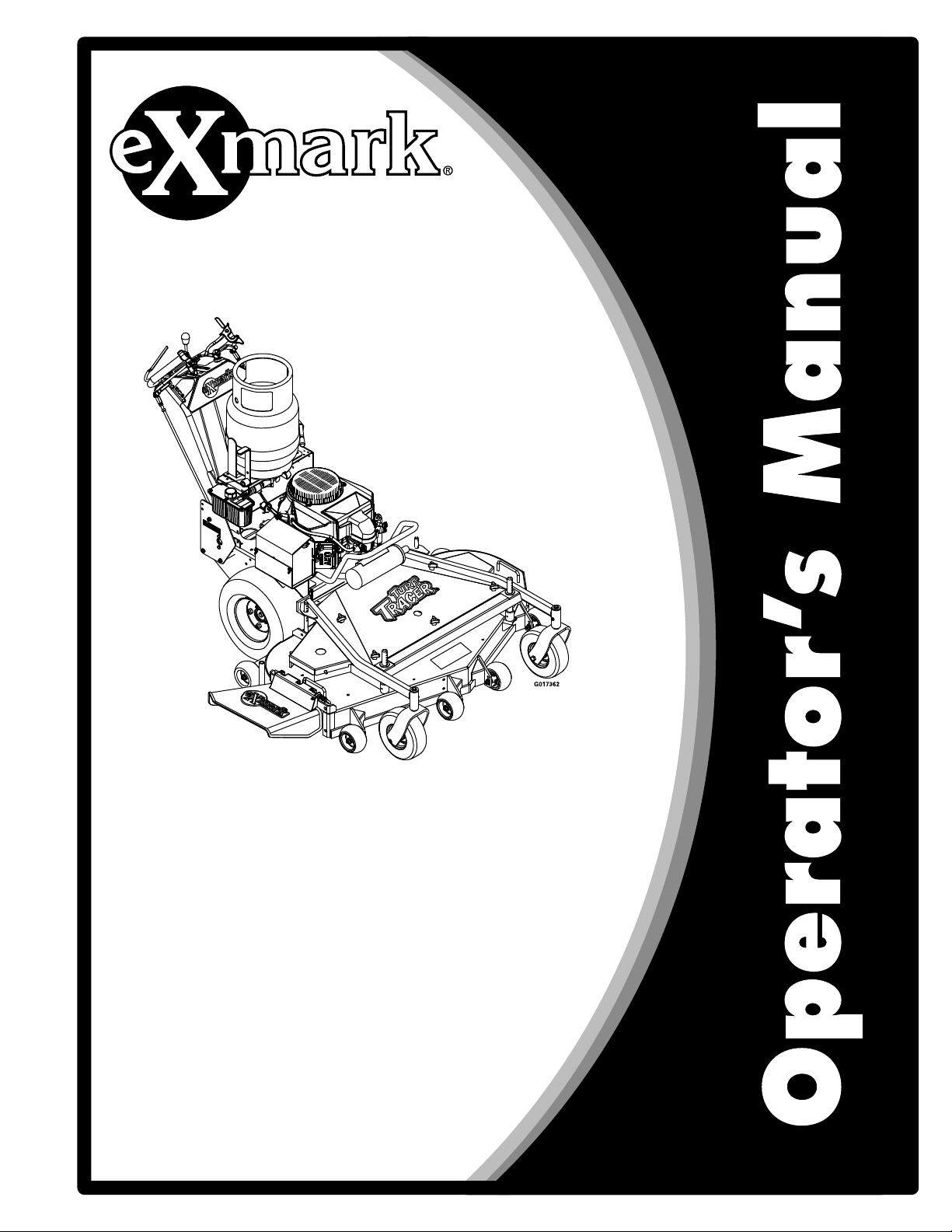
1-413214
1-303517
1-413327
1-403005
1-413421
12
Page 13

Safety
103-2076
1-553049
98-5954
103-2103
103-1798
103–2242
103-1976
13
Page 14
Safety
103–2243
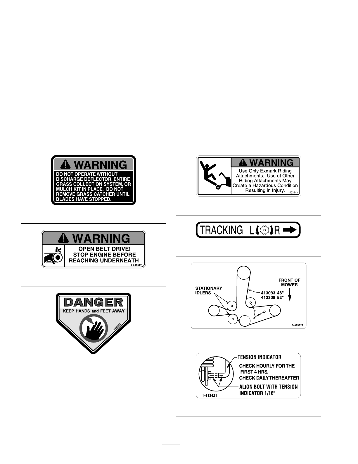
109-9875
103-4935
109-3148
116-0404
109-9870
14
Page 15
Safety
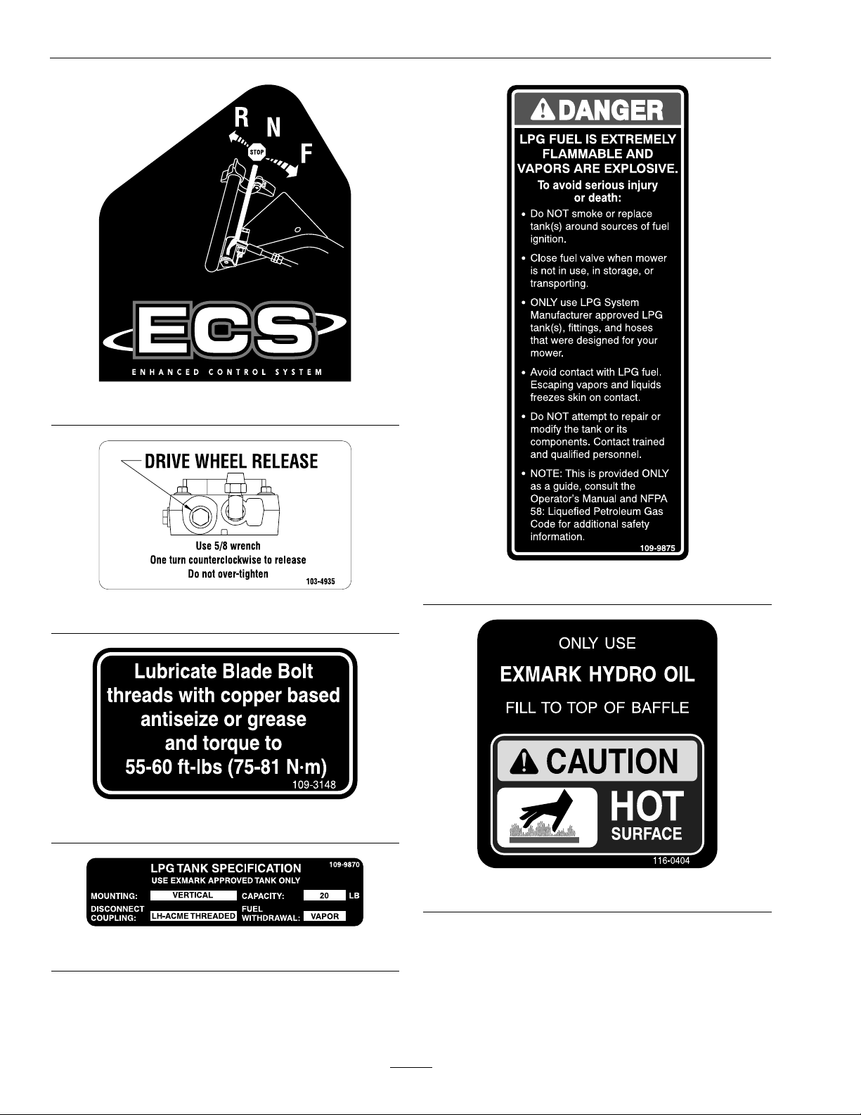
117–2718
109-9906
15
Page 16

Specications
Specications
ModelNumbers
SerialNos:312,000,000andHigher
TTS600PKAE483
Systems
Engine
•EngineSpecications:SeeyourEngineOwner’s
Manual
•EngineOilType:Exmark4–CyclePremium
EngineOil
•RPM:FullSpeed:3600±50RPM(NoLoad)Idle:
1550RPM
TankTypeandRelling
Important:TheLPGtankusedonthismower
isaspecialtankwithinternalbafesdesigned
forthisapplication.
•VerticalTankSpecications:
–TankMaterial:Steel
–Capacity:20lb
–DisconnectCoupling:LHACMEThreaded
–FuelWithdrawal:Vapor
–FuelShut-OffValve:Rotateclockwiseto
close.
•TypeofFuel:HD5gradepropane
•Newtanksmustbeproperlylledbytrainedand
qualiedpersonnel.
Note:Useofa“forklift”typeliquidwithdrawaltank
willresultinicingorfreezingoftheLPGregulator
andpreventtheenginefromoperating.Thismay
alsoresultinpermanentfuelsystemdamageandthe
releaseofhighlyammablepropaneliquidorvapor.
ElectricalSystem
•ChargingSystem:FlywheelAlternator
•ChargingCapacity:15amps
•BatteryType:BCIGroupU1235amps0°F
•BatteryVoltage:12Volt
•Polarity:NegativeGround
•Fuses:Twobladetype,20amptochargingcircuit;
20amptoelectricclutch
SafetyInterlockSystem:
•OperatormusthaveOPC(OperatorPresence
Control)leversheldincontactwithhandle
grips,speedcontrolleverinneutral,andPTO
disengagedtostartengine.ReleaseofOPClevers
willcausetheenginetostopifspeedcontrollever
isnotinneutraland/orPTOisengaged.
•Parkbrakemustbedisengagedtomovespeed
controloutofneutralorenginewillkill.
•OnlyusetanksrecommendedbyExmark.Failure
todosowillresultinimproperoperationofthe
fuelsystem.
CAUTION
Undernocircumstancesshouldpropane
tankslledbeyond80%capacitybeusedin
service.
Theuseofoverlledtanksmayresultinthe
releaseofhighlyconcentratedandextremely
ammableliquidpropane.RefertotheSafety
section.
OperatorControls
SteeringControl:Fingertipdrivecontrollevers
provideindependentspeedcontrol,brakingand
neutraltoeachdrivewheelformovingforwardor
reverse,stopping,andpowerturning.
Transmission
TwinHydrostaticDrive
•TwoHydroGearvariabledisplacementhigh
efciencypumpsindependentlycoupledtotwo
highefciencyParker/Rosswheeldrivemotors.
16
Page 17

Specications
•HydraulicOil:UseExmarkPremiumHydroOil.
•HydraulicOilCapacity:2.4qt.(2.2L)
•HydraulicFilterisreplaceablecartridgetype.
P/N109-4180:25microns,10psibypass
(Summeruseabove32°F(0°C))
P/N1-523541:40microns,18psibypass(Winter
usebelow32°F(0°C))
•Speeds:
–0-6.2mph(10.0km/hr)forward.
–0-2.2mph(3.5km/hr)reverse.
•Drivewheelsreleasevalvesallowmachinetobe
movedwhenengineisnotrunning.
WheelDriveSystem
DrivewheelsaredirectcoupledtoParkerwheeldrive
motorswith1inch(25.4mm)taperedshaft.
Tires&Wheels
•MulchingKit:Optional
•Bagger:Optional
Dimensions
OverallWidth:
DeectorUp48.1inches(122.2cm)
DeectorDown58.25inches(148.0cm)
OverallLength:
73.7inches(187.2cm)
OverallHeight:
44.1inches(112.0cm)
TreadWidth:(OutsidetoOutsideof
Tires,Widthwise)
Drive
Pneumatic
(Air-Filled)
Quantity
Tread
Size16x7.50–89x3.50-4
PlyRating
Pressure
22
TurfMasterSmooth
4
14psi
(97kPa)
FrontCaster
SemiPneumatic
CuttingDeck
•CuttingWidth:47.25inches(120.0cm)
•Discharge:Side
•BladeSize:16.25inches(41.3cm)—Quantity:3
•DeckDrive:Manualengagementofbeltwith
over-centerlock.Bladebelttensionisadjustable
viaturnbuckle.
•DeckMounting:Fulloatingdeckisattachedto
out-frontsupportframe,removableforservice.
39.4inches(100.1cm)
CurbWeight:
689lb(313kg)
•DeckDepth:48inchDeck:5.0inches(12.7cm)
•CuttingHeightAdjustment:
Adjustsfrom11/2inches(3.8cm)to41/2
inches(11.4cm)in1/2inch(1.3cm)increments
17
Page 18

ProductOverview
TorqueRequirements
BoltLocation
CutterHousingSpindle
Nut
BladeMountingBolt
(lubricatewithanti-seize)
EngineDeck/MowerDeck
SupportMountBolts
Anti-ScalpRollerNyloc
NutSee
Anti-ScalpRollerWhizlock
NutSeeFigure9
EngineMountingBolts
WheelLugNuts
WheelHubSlottedNut140-155ft-lb
WheelMotorMounting
Bolts
MuferGuardMounting
Bolts
Figure9
Torque
140-145ft-lb
(190-197N-m)
55-60ft-lb(75-81N-m)
30-35ft-lb(41-47N-m)
30-35ft-lb(41-47N-m)
30-35ft-lb(41-47N-m)
15-20ft-lb(20-27N-m)
90-95ft-lb(122-129N-m)
(190-210N-m)
30-35ft-lb(41-47N-m)
30-35ft-lb(41-47N-m)
ProductOverview
Figure3
1.ParkBrakeLever
2.Controls4.Height-of-CutPins
3.LPGFuelT ank
18
Page 19

Operation
Operation
Note:Determinetheleftandrightsidesofthe
machinefromthenormaloperatingposition.
Controls
OperatorPresenceControl(OPC)
Levers
Locatedontheupperhandleassemblydirectlyabove
thehandlegrips.
Whentheseleversaredepressed,theOPCsystem
sensesthattheoperatorisinthenormaloperator's
position.Whentheleversarereleased,theOPC
systemsensesthattheoperatorhasmovedfromthe
normaloperatingpositionandwillkilltheengineif
eitherthespeedcontrolleverisnotintheneutral
positionorthePTOisengaged.
asshowninFigure4,andthedriveleversarereleased,
thedrivewheelsareengagedintheforwarddirection.
Squeezingthelefthandand/orrighthandlever
causesthelefthandand/orrighthanddrivewheel
respectivelytoslowdown,stop,orreverse,depending
onhowfareachdriveleveris“squeezed”.Squeezing
thedriveleversbeyondtheneutralpositioncauses
thedrivewheelstoengageinthereversedirection
regardlessofthepositionoftheneutrallocklatches
andthespeedcontrollever.
NeutralLockLatches
Locatedontheupperhandleassemblyontheends
ofthehandlegrips.
Theselatchesallowtheoperatortolockthedrive
leversina“neutral”positionwherethedrivewheels
arenotengagedineitheraforwardorreverse
direction.
ThrottleControl
Locatedonthecontrolconsole’ srightside.
Figure4
1.OPCLever
2.Rotateneutrallocklatch
downwardforneutral
lockposition
3.NeutralLockLatch
4.DriveLeverinneutral
position
DriveLevers
Locatedoneachsideoftheupperhandleassembly
aheadofandbelowthehandlegrips.
Theseleversindividuallycontrolthespeedand
directionofeachdrivewheel.Whenthespeedcontrol
leverismovedoutoftheneutralpositionandthe
neutrallocklatchesaremovedintothedriveposition,
Thethrottleisusedtocontrolenginespeed.Moving
thethrottlecontrolforwardwillincreaseenginespeed
andmovingittotherearwilldecreaseenginespeed.
Movingthethrottleforwardintothedetentisfull
position.
SpeedControlLever
Locatedinmiddleofcontrolconsole.
Thespeedcontrollevercontrolsthemaximum
forwardspeedandisinnitelyvariablefromneutral
0–6.2mph(10.0km/hr).
Parkbrakemustbedisengagedtomovespeedcontrol
outofneutralorenginewillkill.
ParkBrakeLever
Locatedontheleftsideoftheunitabovethe
hydraulictank.
Thebrakeleverengagestheparkbrakeonthedrive
wheels.
Pulltheleverupandrearwardtoengagethebrake.
Pushtheleverforwardanddowntodisengagethe
brake.
Whenparkingonasteepslope,thewheelsmustbe
chockedorblockedinadditiontothebrakebeing
19
Page 20

Operation
engaged.Theunitmustbetieddownandbrake
engagedwhentransporting.
Theparkbrakemustbedisengagedtomovespeed
controloutofneutralorenginewillkill.
Formanualstartengines:Theparkbrakemustbe
disengagedbeforethePTOisengagedortheengine
willkill.
IgnitionSwitch
Locatedontheleftsideofthecontrolconsole.
Theignitionswitchisusedtostartandstopthe
engine.Theignitionswitchhasthreepositions,
“Off”,“On”and“Start”.Insertkeyintoswitch
androtateclockwisetothe“On”position.Rotate
clockwisetothenextpositiontoengagethestarter
(keymustbeheldagainstspringpressureinthis
position).Operatormusthavespeedcontrolleverin
neutral,OPCleversdepressedandPTOdisengaged
tostartengine.Whenenginestarts,releasekey.
FuelValve
LocatedontheLPGfueltank.
Thefuelvalveisusedtoopenandclosethefuel
supplywhenthemachineisnotinuse,during
transporttoandfromthejobsite,andwhenparked
insideawell-ventilatedbuilding.
Rotatethefuelvalveclockwisetoturnoffthefuel.
Rotatefuelvalvecounter-clockwisetoturnonthe
fuel.
DriveWheelReleaseValves
Locatedontheleftrearcornerofthehydrostatic
pumps.
Theknobcanbeadjustedsothatmachinewill“track”
straightaheadwiththedriveleversreleased.
PTOEngagement
Locatedontheleftsideoftheupperhandle.
Toengagetheblades,pushtheleverforward,oraway
fromtheoperator,untilthelinkagelocksover-center.
Todisengagetheblades,pullthelevertotherear,
ortowardstheoperator.
Formanualstartengines:Theparkbrakemustbe
disengagedbeforethePTOisengagedortheengine
willkill.
LPGCylinderBracket
Thebracketislocatedontheenginedeck.
TheLPGcylinderbracketisusedtofastenthe
removableLPGtanktothemower.
FuelGauge
LocatedontheLPGfueltank.
ThisgaugemonitorstheamountofliquidLPGin
thefueltank.
SafetyPressureReliefValve
LocatedontheLPGfueltank.
Thesafetypressurereliefvalverelievestheexcess
pressureintheLPGtank.
Important:Thisvalvehasaprotectiveplastic
capthatshouldNEVERberemoved.Ifthe
capisdamagedormissing,contacttrainedand
qualiedpersonnelimmediately.
Drivewheelreleasevalvesareusedtoreleasethe
hydro-staticdrivesystemtoallowthemachinetobe
movedbyhandwithouttheenginerunning.
Witha5/8wrench,turnbothvalvesoneturn
counterclockwisetoreleasethedrivesystem.
Turnclockwisetoresetthedrivesystem.DoNot
overtighten.
TrackingAdjustmentKnob
Locatedontheright-handsideoftherearofthefuel
tanksupport.
Pre-Start
LPGtankssuppliedfromExmarkDoNotcontain
LPGfuel.HavetheLPGtankslledbytrainedand
qualiedpersonnel.Forbestresults,useclean,fresh
HD5gradepropane.
DoNotallowtheLPGtankstobeoverlled.
OverllingLPGtanksbuildsexcesspressurewithin
thetankwhichcausesthereliefvalvetoopen.
Makesureyouunderstandthecontrols,their
locations,theirfunctions,andtheirsafety
requirements.
20
Page 21

Operation
RefertotheMaintenancesectionandperformallthe
necessaryinspectionandmaintenancesteps.
Note:Afterstartingtheengineandengagingthe
hydrodrive,ifeitherofthedrivewheelsactssluggish
orwillnotrotateatall,stopengineandreferto
theHydraulicSystemAirPurgeProcedurein
Maintenance.
OperatingInstructions
Important:Ifatanytimeyousensesomething
iswrongwiththeLPGequipment,stopthe
mowerinasafelocationandturnthemoweroff.
Ifyoucansafelydoso,closethefuelvalveand
trytondthecause;otherwise,getawayfrom
themowerandcontacttrainedandqualied
personnelimmediately.
OpentheFuelValve
1.Slowlyopenthefuelvalvetoequalizethepressure
inthetank.Thefuelvalveislocatedonthetop
oftheLPGtank.Ifthefuelvalveisopenedtoo
quickly,thepressurereliefvalveisequippedwith
abackpressurecheckvalvethatwillshutoffthe
fuelsupply.Ifthishappens,closethefuelvalve
completelyandwaitveseconds.Slowlyopen
thefuelvalve.
2.Rotatethefuelvalvecounter-clockwisetoturnon
thefuel.Ifleaksaredetected,refertotheleak
informationintheInspectionsectioninSafety .
StartingtheEngine
Note:OperatormusthavePTOdisengaged,speed
controlleverinneutralposition,andOPClevers
depressedwhenstartingtheengine.
1.PushinonthePTOswitchtothe“STOP”
position.
2.Placethethrottleinthe“SLOW”position.
3.Turnignitionswitchto“Start”position.Release
theswitchassoonastheenginestarts.
Important:DoNotcranktheengine
continuouslyformorethantensecondsat
atime.Iftheenginedoesnotstart,allowa
60secondstartercool-downperiodbetween
startingattempts.Failuretofollowthese
guidelinescanburnoutthestartermotor.
Note:Itishelpfultohavetheleftandright
neutrallocklatcheslockedinneutralwhenstarting
theengine.RefertoNeutralLockLatches
sectioninControls.
PTOEngagement
DANGER
Therotatingbladesunderthemowerdeckare
dangerous.Bladecontactcancauseserious
injuryorkillyou.
DoNotputhandsorfeetunderthemoweror
mowerdeckwhenthebladesareengaged.
DANGER
Anuncovereddischargeopeningwillallow
objectstobethrowninanoperator’sor
bystander’sdirection.Also,contactwiththe
bladecouldoccur.Thrownobjectsorblade
contactcancauseseriousinjuryordeath.
Neveroperatethemowerwiththedischarge
deectorraised,removed,oralteredunlessthere
isagrasscollectionsystemormulchkitinplace
andworkingproperly.
ThePTOswitchengagesthecuttingblades.Besure
thatallpersonsareclearofmowerdeckanddischarge
areabeforeengagingthePTO.
1.Setthrottleto“MIDW AY”position.
2.PushthePTOengagementarmforwardand
downtoengageblades.
3.Placethethrottleinthe“FAST”positiontobegin
mowing.
DisengagingthePTO
1.Setthrottleto“MIDW AY”position.
2.PullupwardandbackcompletelyonthePTO
engagementarmtodisengagetheblades.
StoppingtheEngine
1.Bringthemowertoafullstop.
2.Lockdriveleversinneutral.
3.DisengagethePTO.
4.Movespeedcontrollevertoneutral.
5.Engagetheparkingbrake.
6.Placethethrottleinthe“SLOW”position.
21
Page 22

Operation
7.Turnoffthefuelvalve(s)andallowtheengineto
runoutoffuel.Failuretodothismaycausethe
engineto“ood”whenre-starting.
8.Turntheignitionswitchtothe“OFF”position
oncetheenginehasstopped.
9.Removethekeytopreventchildrenorother
unauthorizedpersonsfromstartingengine.
Important:ThereareNOadjustments
necessaryfortheLPGmower.DoNotmakeany
adjustmentstotheregulatororcarburetor.If
theengineisnotrunningproperly,contactan
AuthorizedServiceDealer.
Figure5
DrivingtheMachine
DriveLever/NeutralLockLatchOperation
Tolockthedriveleversin“neutrallock”,squeezethe
driveleverstothe“neutral”position(DoNotsqueeze
thedriveleversallthewaybackasthiswillcausethe
drivewheelstogointofullreversedirection).See
Figure5position1.Placethumbsontheinnerlobe
oftheneutrallocklatchesandrotatethemunder
thedriveleversintothe“neutrallock”position.See
Figure5position2.Releasethedrivelevers.
CAUTION
Iftheneutrallocklatchesarenotcompletely
engagedthedriveleverscouldunexpectedlyslip
intotheforwarddriveposition.Ifthedrivelevers
slipintothedrivepositiontheunitcouldlurch
forwardandcauseinjuryorpropertydamage.
Besurethedriveleversarepasttherollerand
securelyseatedatthebottomoftheneutrallock
latches.
Toplacethedriveleversinthe“forward”position,
slightlysqueezethedriveleverswhileplacingthumbs
ontheouterthumblobeoftheneutrallocklatches
(ortheindexngeronthefrontlobe)androtatethem
fromunderthedrivelevers.Slowlyandcarefully
releasethedrivelevers.SeeFigure5position3.
Toplacethedriveleversinthe“reverse”position,
squeezethedriveleverspasttheneutralposition.See
Figure5position4.
1.DriveLeverinneutral
position
2.DriveLeverlockedin
neutralposition
3.DriveLeverinforward
position
4.DriveLeverinreverse
position
DrivingForward
1.Releasetheparkingbrake.
2.Withdriveleverslockedin“neutral”,shiftspeed
controllevertodesiredforwardspeed.
3.Slowlysqueezeandholdbothdriveleversin
theneutralpositionandrotatebothneutrallock
latchesfromtheneutrallockpositiontothe
forwardposition.
Note:DoNotsqueezebothdriveleversallthe
wayback.Thiswillcausethedrivewheelsto
engageinthereversedirection.
4.Tomoveforwardinastraightline,smoothly
releasebothdriveleverstoengagedrivewheels.
Toturnleftorright,squeezetherighthanddrive
levertoturnrightandthelefthanddrivelever
toturnleft.
Tomakea“zeroturn”,squeezeeithertheleft
handortherighthanddriveleverbackintothe
reversepositionwhiletheoppositedriveleverisin
aforwardpositionatanequalbutoppositespeed.
Note:Forsmoothoperationofthismachine,
avoidquick,jerkymovementsofthedrivelevers.
Movethedriveleverssmoothlyanddeliberately.
Tostop,squeezedriveleversbacktothe“neutral”
position.Movetheneutrallocklatchesintothe
“neutrallock”positionandreleasedrivelevers.
Movethespeedcontrollevertotheneutral
position.
22
Page 23

DrivinginReverse
Tomoverearwardinastraightline,squeezedrive
leversintothereverseposition.
Toturnleftorright,squeezetherighthanddrivelever
toturnleftandthelefthanddrivelevertoturnright.
Tomakea“zeroturn”,squeezeeitherthelefthand
ortherighthanddriveleverbackintothereverse
positionwhiletheoppositedriveleverisinaforward
positionatanequalbutoppositespeed.
Note:Forsmoothoperationofthismachine,avoid
quick,jerkymovementsofthedrivelevers.Movethe
driveleverssmoothlyanddeliberately.
Tostop,squeezedriveleversbacktothe“neutral”
position.Movetheneutrallocklatchesintothe
“neutrallock”positionandreleasedrivelevers.Move
thespeedcontrollevertotheneutralposition.
AdjustingtheCuttingHeight
WARNING
Whenthetwofrontsupportrodhairpinsare
removedfromthemowerdeck,theweightofthe
tractorsectionmaycausethefrontframeofthe
unittorisesuddenly.Iftheunitrisessuddenly,
injurymayoccur.
Securelyholddownthefrontoftheunitwhenthe
frontsupportrodhairpinsareremoved.
Operation
Figure6
1.Decksupportpin
B.ThetirepressuresaresetasdirectedinCheck
TirePressuresintheMaintenancesection.
C.Thelengthofthereardecksupportlink
assembliesaverage6.89inches(approximately
67/8inches)(175.01mm)fromthecenterof
theballjointtothecenterofthefarthesthole.
Figure7.
See
Note:Allfourpinsmustequallysupportthe
weightofthedeck.Adjustmentinthelength
ofthereardecksupportassembliesmaybe
necessary.Ifonesideislongerthan6.89
inches(approximately67/8inches)(175.01
mm),thantheoppositesidemustbeshorter
bythesameamount.
2.CuttingHeight
Thecuttingheightofthemowerdeckisadjusted
from11/2to41/2inches(3.81cmto11.4cm)in
1/2inchincrements.
1.Stopthemachineandmovethedriveleverstothe
neutrallockedposition.
2.DisengagethePTO.
3.Engagetheparkbrake.
4.Stoptheengine,removethekeyandwaitforall
movingpartstostop.
5.Installhairpinclipsintheholesforthedesired
cuttingheight.SeeFigure6.
Important:T omaintaincorrectcutting
heightandrake,checkthefollowingfor
properadjustment.
A.Thefrontandrearhairpinsareinthesame
holeswiththeproperspacersunderthehair
pins.SeeFigure6.
Figure7
LeftHandSideShown
23
Page 24

Operation
AdjustingtheAnti-ScalpRollers
Itisrecommendedtochangetheanti-scalproller
positionwhentheheightofcuthaschanged.
1.Stopthemachineandmovethedriveleversto
theneutrallockposition.
2.DisengagethePTO.
3.Engagetheparkbrake.
4.Stoptheengine,removethekeyandwaitforall
movingpartstostop.
5.Afteradjustingtheheightofcut,adjustthe
anti-scalprollersbyremovingthewhizlocknut
andspringdiscwasher.
6.Adjustanti-scalprollersforNormalOperating
Conditions.Placerollersinoneofthepositions
shownin
inches(19mm)clearancetothegroundto
minimizegougingandrollerwearordamage.
Figure8.Rollerswillmaintain3/4
1.Springdiscwasher
(conetowardsnut)
2.Frontrightanti-scalp
bracketshown
Figure9
3.3/8nyloc-torqueto30-35
ft-lb(41-47N-m)
4.3/8-16whizlocknut
torqueto30-35ft-lb
(41-47N-m)
Note:ForMaximumDeckFlotation,place
rollersoneholepositionlower.Rollersshould
maintain1/4inch(6.35mm)clearancetoground.
DoNotadjustrollerstosupportthedeck.Be
surerollerboltsareinstalledwiththespringdisc
washerbetweenheadofthenutandmounting
bracket.
Figure8
Forcuttingheightsabove3.5inches(38mm)usethe
bottomhole.Therollerswillstillbeeffectiveagainst
scalping.
1.Anti-scalproller
mountingbracket
2.Cuttingheight
7.Torquethe3/8–16whizlocknutto30-35ft-lb
(41-47N-m)(Figure9).
8.Ifthe3/8nylocnuthasbeenremoved,reinstall
andtorqueto30–35ft-lb(41-47N-m)(Figure9).
Transporting
TransportingaUnit
WARNING
Loadingthemowerontoatrailerwithoutstrong
enoughorproperlysupportedrampscouldbe
dangerous.Therampscouldcollapsecausing
theunittofall,whichcouldcauseinjury.
•Useproperrampsthataresecuredtothe
truckortrailer.
•Keepfeetandlegsoutfromundertheunit
whenloadingandunloading.
•Ifnecessary,useassistancewhenloading .
ConsulttheNFPA58:LiqueedPetroleumGas
CodeforadditionalinformationregardingLPG
transportation.
•Besurethefuelvalveisclosed.
•PlacespareLPGtank(s)inaDOTapproved
storagecage.
–Transporttanksinanupright,verticaland
securepositiontominimizemovement,
tipping,orphysicaldamagerelativetoother
tanksortothestoragecagewhileintransit.
–Placetankssothatvalves,ttings,orgauges
areprotectedfromphysicaldamageduring
transport.
24
Page 25

•Placetank(s)inawell-ventilatedtrailer.
•DoNotstorethetank(s)ormachinewith
tank(s)inanareawherethetemperaturecanrise
above120°F(49°C).Ifthetemperatureexceeds
approximately160°F(71°C),thetankwillrelease
highlyammablepropanevapor.SeePreparation
intheSafetySection.
•DoNottransportLPGtank(s)inthepassenger
spaceofavehicle.
•DoNottransportleakingfueltanks.
•Trailersmusthaveappropriatemarkingsto
transportLPG.
•FollowNFPA58andstateandlocalregulations
fortransportingLPG.
•Useaheavydutytrailertotransportthemachine.
Engageneutrallocklatchesandparkbrake,then
blockwheels.
Operation
•Securelyfastenthemachinetothetrailerwith
straps,chains,cables,orropes.
•DoNotrelysolelyontheparkingbraketohold
themachineonthetrailer.
•Besurethatthetrailerhasallnecessarylighting
andmarkingasrequiredbylawanduseasafety
chain.
25
Page 26

Maintenance
Maintenance
Note:Determinetheleftandrightsidesofthemachinefromthenormaloperatingposition.
WARNING
Whilemaintenanceoradjustmentsarebeing
made,someonecouldstarttheengine.
Accidentalstartingoftheenginecouldseriously
injureyouorotherbystanders.
Removethekeyfromtheignitionswitch,engage
parkingbrake,andpullthewire(s)offthespark
plug(s)beforeyoudoanymaintenance.Also
pushthewire(s)asidesoitdoesnotaccidentally
contactthesparkplug(s).
RecommendedMaintenanceSchedule(s)
MaintenanceService
Interval
Aftertherst2hours
Aftertherst5hours
Aftertherst100hours
Aftertherst250hours
MaintenanceProcedure
•InspectPTOclutchingbelttension.Checkevery2hoursfortherst8hoursofoperation.
•Changetheengineoil.
•Checkwheelhub-slottedtorquespecication.
•Changethehydrauliclter.
WARNING
Theenginecanbecomeveryhot.Touchingahot
enginecancausesevereburns.
Allowtheenginetocoolcompletelybefore
serviceormakingrepairsaroundtheenginearea.
Beforeeachuseordaily
Every25hours
Every40hours
Every80hours
Every100hours
Every160hours
•Checktheengineoillevel.
•Checkthemowerblades.
•Checkthesafetyinterlocksystem.
•Checkforloosehardware.
•Greasethecasterwheelbearings.
•Greasecasterpivots.
•ChecktheLPGtankandcomponents.
•Cleantheengineandexhaustsystemarea.
•Cleanthegrassanddebrisbuild-upfromthemachineandcuttingdeck.
•Cleanthegrassbuild-upfromunderthedeck.
•Servicetheaircleaner.(Mayneedmoreoftenundersevereconditions.SeetheEngine
Owner'smanualforadditionalinformation.)
•Checkthehydraulicoillevel.
•Checkthetirepressures.
•Checktheconditionofthebelts.
•Greasethepumpdriveidlerpivot.
•Greasetheclutcharmpivot.
•Greasethepumpcontrolbearings.
•Greasethemowerdeckidlerpivot.
•ChecktheentireLPGfueldeliverysystem.
•InspectPTOclutchingbelttension.
•Removeengineshroudsandcleancoolingns.
•Changetheengineoil.(Mayneedmoreoftenundersevereconditions.)
•Checkthesparkplugs.(SeeCheckSparkPlugsectionforpropersparkpluggap.)
26
Page 27

Maintenance
MaintenanceService
Interval
Every500hours
Monthly
MaintenanceProcedure
•Changethehydrauliclter(Every250hours/yearlyifusingMobil115W50)
•Checkwheelhub-slottedtorquespecication.
•Checkthebatterycharge.
•GreasethePTOengagementbellcrank.
PeriodicMaintenance
CheckEngineOilLevel
ServiceInterval:Beforeeachuseordaily
1.Stopengineandwaitforallmovingpartstostop.
Makesureunitisonalevelsurface.
2.Checkwithenginecold.
3.Cleanareaarounddipstick.Removedipstickand
wipeoiloff.Reinsertthedipstickandpushitall
thewaydownintothetube.DoNotscrewinto
place.Removethedipstickandreadtheoillevel.
4.Iftheoillevelislow ,wipeofftheareaaroundthe
oilllcap,removecapandlltothe“FULL”
markonthedipstick.Exmark4-CyclePremium
EngineOilisrecommended;refertotheEngine
Owner'smanualforanacceptablealternative.Do
Notoverll.
Important:DoNotoperatetheenginewiththe
oillevelbelowthe“LOW”(or“ADD”)markon
thedipstick,oroverthe“FULL”mark.
CheckBatteryCharge
ServiceInterval:Monthly
WARNING
CALIFORNIA
Proposition65Warning
Batteryposts,terminals,andrelated
accessoriescontainleadandlead
compounds,chemicalsknowntotheStateof
Californiatocausecancerandreproductive
harm.Washhandsafterhandling.
storagewhentheopencircuitvoltagedropsto12.4
volts.
Note:Topreventdamageduetofreezing,battery
shouldbefullychargedbeforeputtingawayfor
winterstorage.
Checkthevoltageofthebatterywithadigital
voltmeter.Locatethevoltagereadingofthebatteryin
thetableandchargethebatteryfortherecommended
timeintervaltobringthechargeuptoafullcharge
of12.6voltsorgreater.
Important:Makesurethenegativebatterycable
isdisconnectedandthebatterychargerusedfor
chargingthebatteryhasanoutputof16voltsand
7ampsorlesstoavoiddamagingthebattery(see
chartforrecommendedchargersettings).
Voltage
Reading
12.6or
greater
12.4–12.675–100%
12.2–12.450–75%
12.0–12.225–50%
11.7–12.00–25%
11.7orless
Percent
Charge
100%
0%
Maximum
Charger
Settings
16volts/7
amps
16volts/7
amps
16volts/7
amps
14.4volts/4
amps
14.4volts/4
amps
14.4volts/2
amps
Charging
Interval
No
Charging
Required
30Minutes
1Hour
2Hours
3Hours
6Hoursor
More
RecommendedJump
Allowingbatteriestostandforanextendedperiodof
timewithoutrechargingthemwillresultinreduced
performanceandservicelife.Topreserveoptimum
batteryperformanceandlife,rechargebatteriesin
StartingProcedure
ServiceInterval:Asrequired
1.Checktheweakbatteryforterminalcorrosion
(white,green,orblue“snow”),itmustbecleaned
27
Page 28

Maintenance
offpriortojumpstarting.Cleanandtighten
connectionsasnecessary.
CAUTION
Corrosionorlooseconnectionscancause
unwantedelectricalvoltagespikesatanytime
duringthejumpstartingprocedure.
DoNotattempttojumpstartwithlooseor
corrodedbatteryterminalsordamagetothe
enginemayoccur.
DANGER
Jumpstartingaweakbatterythatiscracked,
frozen,haslowelectrolytelevel,oran
open/shortedbatterycell,cancausean
explosionresultinginseriouspersonalinjury.
DoNotjumpstartaweakbatteryifthese
conditionsexist.
2.Makesuretheboosterisagoodandfullycharged
leadacidbatteryat12.6voltsorgreater.Use
properlysizedjumpercables(4to6A WG)with
shortlengthstoreducevoltagedropbetween
systems.Makesurethecablesarecolorcodedor
labeledforthecorrectpolarity.
CAUTION
Connectingthejumpercablesincorrectly
(wrongpolarity)canimmediatelydamagethe
electricalsystem.
Becertainofbatteryterminalpolarityand
jumpercablepolaritywhenhookingup
batteries.
Note:Thefollowinginstructionsareadapted
fromtheSAEJ1494Rev .Dec.2001–Battery
BoosterCables–SurfaceVehicleRecommended
Practice(SAE–SocietyofAutomotive
Engineers).
Note:Besuretheventcapsaretightandlevel.
Placeadampcloth,ifavailable,overanyvent
capsonbothbatteries.Besurethevehiclesdo
nottouchandthatbothelectricalsystemsare
offandatthesameratedsystemvoltage.These
instructionsarefornegativegroundsystemsonly .
3.Connectthepositive(+)cabletothepositive(+)
terminalofthedischargedbatterythatiswiredto
thestarterorsolenoidasshownin
Figure10
1.Positive(+)cableondischargedbattery
2.Positive(+)cableonboosterbattery
3.Negative(–)cableontheboosterbattery
4.Negative(–)cableontheengineblock
5.Boosterbattery
6.Dischargedbattery
7.Engineblock
Figure10.
4.Connecttheotherendofthepositivecabletothe
positiveterminaloftheboosterbattery.
5.Connecttheblacknegative(–)cabletotheother
terminal(negative)oftheboosterbattery.
6.MAKETHEFINALCONNECTIONON
THEENGINEBLOCKOFTHESTALLED
VEHICLE(NOTTOTHENEGATIVEPOST)
AWAYFROMTHEBATTERY .STANDBACK.
7.Startthevehicleandremovethecablesinthe
reverseorderofconnection(theengineblock
(black)connectionisthersttodisconnect).
WARNING
Batteriescontainacidandproduceexplosive
gases.
•Shieldtheeyesandfacefromthebatteries
atalltimes.
•DoNotleanoverthebatteries.
CheckMowerBlades
ServiceInterval:Beforeeachuseordaily
1.Stopengine,waitforallmovingpartstostop,and
removekey.Engageparkingbrake.
2.Liftdeckandsecureinraisedpositionasstatedin
theCleanGrassBuild-UpUnderDecksection.
28
Page 29

Maintenance
3.Inspectbladesandsharpenorreplaceasrequired.
4.Reinstalltheblades(iftheywereremoved)inthe
followingorder:
A.Installbushingthroughbladewithbushing
angeonbottom(grass)sideofblade.
Figure11
1.Installbushinginbladepriortoinstallingbushingin
spindle.
B.Installbushing/bladeassemblyintospindle.
WARNING
Incorrectinstallationofthebladeor
componentsusedtoretainthebladecan
bedangerous.Failuretousealloriginal
componentsandassembledasshowncould
allowabladeorbladecomponenttobe
thrownoutfromunderthedeckresultingin
seriouspersonalinjuryordeath.
AlwaysinstalltheoriginalExmarkblades,
bladebushings,andbladeboltsasshown.
ReplacingtheDischarge
Deector
ServiceInterval:Asrequired
DANGER
Anuncovereddischargeopeningcouldallowthe
lawnmowertothrowobjectsintheoperator’sor
bystander’sdirectionandresultinseriousinjury.
Also,contactwiththebladecouldoccur.
Figure12
1.Usewrenchherefor
bladeinstallation.This
nuthasbeentorquedto
140–145ft-lb(190–197
N-m)
2.Torqueto55-60ft-lb
(75-81N-m)Apply
lubricanttothreads
asneededtoprevent
seizing.Copper-based
anti-seizepreferable.
Greaseacceptable
substitute.
C.Applylubricanttothreadsofbladeboltas
neededtopreventseizing.Copper-based
anti-seizepreferable.Greaseacceptable
substitute.Installbladeboltngertight.Place
wrenchonthetopspindlenutthentorquethe
bladeboltsto55-60ft-lb(75-81N-m).
Neveroperatethelawnmowerunlessyouinstall
amulchplate,dischargedeector,orgrass
collectionsystem.
1.Toremoveadamagedorworndischargedeector,
liftthelegofthespringwiththeloopoutofthe
notchinthedischargedeectorandslidethe
rodoutofthedischargedeectorbrackets,and
dischargedeector.
2.Toinstallnewdischargedeector,orientthe
springontherodasshownin
Figure13.Slidethe
rodthroughthefrontdischargedeectorbracket,
dischargedeector,andreardeectorbracket.
29
Page 30

Maintenance
Figure13
1.Rod4.Mowerdeck
2.Spring5.Dischargedeector
3.Dischargedeector
3.Hookthebentendoftherodaroundthefront
dischargedeectorbrackettoretainitfrom
slidingout.Placethelegofthespringwiththe
loopinthenotchinthedischargedeectorto
holdthedischargedeectorinthedownposition
Figure13).
(see
Important:Thedischargedeectormustbe
springloadedinthedownposition.Liftthe
deectoruptotestthatitsnapstothefull
downposition.
bracket
6.Assembledview
Trytostartwith,OPCleversdepressed,speed
controlleverinanyspeedbutneutralandPTO
disengaged–startermustnotcrank.
TrytostartwithOPCleversdepressed,
speedcontrolleverinneutralandPTO
engaged–startermustnotcrank..
2.ForAllUnits:CheckOPCcircuits.Clearthe
area.Disengagetheparkbrake.Runengineat
one-thirdthrottle,then,withdriveleversand
neutrallocklatchesinneutrallockposition,
movethespeedcontrolleveroutofneutraland
releaseOPClevers–enginemuststop.Again,
runengineatone-thirdthrottle,movethespeed
controllevertoneutral,engagePTOandrelease
OPClevers–enginemuststop.
Note:Parkbrakemustbedisengagedbeforethe
speedcontrolleverismovedoutofneutralorengine
willkill.
ForManualStartEngines:Theparkbrakemustbe
disengagedbeforethePTOisengagedortheengine
willkill.
Note:Ifmachinedoesnotpassanyofthesetests,
donotoperate.ContactyourauthorizedEXMARK
SERVICEDEALER.
Important:Itisessentialthatoperatorsafety
mechanismsbeconnectedandinproper
operatingconditionpriortouseformowing.
CheckforLooseHardware
ServiceInterval:Beforeeachuseordaily
1.Stopengine,waitforallmovingpartstostop,and
removekey.Engageparkingbrake.
CheckSafetyInterlock
System
ServiceInterval:Beforeeachuseordaily
1.ForElectricStartUnitsOnly:Checkstarting
circuit.Startershouldcrankwith:Operator
PresenceControlleversdepressed,speedcontrol
leverinneutral,andPTOdisengaged.
TrytostarttheenginewithOPClevers
disengaged,speedcontrolleverinneutraland
PTOdisengaged–startermustnotcrank.
2.Visuallyinspectmachineforanyloosehardware
oranyotherpossibleproblem.Tightenhardware
orcorrecttheproblembeforeoperating.
ServicePre-CleanerElement
andAirCleaner
ServiceInterval:Every25hours—Service
theaircleaner.(May
needmoreoftenunder
severeconditions.See
theEngineOwner's
manualforadditional
information.)
30
Page 31

Maintenance
1.Stopengine,waitforallmovingpartstostop,and
removekeyorsparkplugwire(s).Engageparking
brake.
2.SeetheEngineOwner'sManualforcleaning
instructions.
ChangeEngineOil
ServiceInterval:Aftertherst5hours
Every100hours(May
needmoreoftenunder
severeconditions.)
1.Stopengine,waitforallmovingpartstostop,and
removekey.Engageparkingbrake.
2.Drainoilwhileengineiswarmfromoperation.
3.Theoildrainhoseassemblyislocatedontheleft
sideoftheengine.
Placepanundermachinetocatchoil.Remove
plugfromendofdrainhose.Allowoiltodrain
andreplaceoildrainplug.Torqueplugto20-24
ft-lb.
4.ReplacetheoillterpertheEngineOwner's
Manual.Cleanaroundoillterandunscrewlter
toremove.Beforethenewlterisinstalled,
applyathincoatingofExmark4–CyclePremium
EngineOilonthesurfaceoftherubberseal.
Turnlterclockwiseuntilrubbersealcontacts
thelteradapter,thentightenlteranadditional
2/3to3/4turn.
5.Cleanaroundoilllcapandremovecap.Fillto
speciedcapacityandreplacecap.
6.UseoilrecommendedintheCheckEngineOil
Levelsection.DoNotoverll.Starttheengine
andcheckforleaks.Stopengineandrecheckoil
level.
CheckHydraulicOilLevel
temperatureoftheoil.The“HOT”levelshows
thelevelofoilwhenitisat225°F(107°C).The
“COLD”levelshowstheleveloftheoilwhen
itisat75°F(24°C).Filltotheappropriatelevel
dependinguponthetemperatureoftheoil.For
example:Iftheoilisabout150°F(65°C),llto
halfwaybetweenthe“HOT”and“COLD”levels.
Iftheoilisatroomtemperature(about75°F
(24°C)),llonlytothe“COLD”level.
CheckTirePressures
ServiceInterval:Every40hours
1.Stopengine,waitforallmovingpartstostop,and
removekey.Engageparkingbrake.
2.Checktirepressureindrivetires.
3.Inatedrivetiresto12–16psi(83–110kPa).
4.Inatetirestopressuresstatedabove.Measure
thecircumferenceofeachdrivetire.Adjusttire
pressureswithintheaboverangetotrytomake
tirecircumferencesmatchascloselyaspossible.
5.Semi-pneumaticcastertiresdonotneedtobe
inated.
CheckConditionOfBelts
ServiceInterval:Every40hours
1.Stopengine,waitforallmovingpartstostop,and
removekey.Engageparkingbrake.
2.Removethemowerdeckbeltshieldtocheck
mowerbladedrivebeltcondition.
3.Lookunderenginedecktocheckthepumpdrive
beltcondition.
4.Checkallidlerarmstobesuretheypivotfreely.
Disassemble,cleanandgreasepivotbushingsif
necessary.
ServiceInterval:Every40hours
1.Stopengineandwaitforallmovingpartstostop,
andremovekey.Engageparkingbrake.
2.Cleanareaaroundhydraulicreservoircapand
removecap.Oillevelshouldbetothetopofthe
bafeinsidethetank.Ifnot,addoil.UseExmark
PremiumHydroOil.Replacehydraulicreservoir
capandtightenuntilsnug.DoNotovertighten.
Note:Thebafeislabeled“HOT”and
“COLD”.Theoillevelvarieswiththe
LubricateGreaseFittings
Note:Seechartforserviceintervals.
1.Stopengine,waitforallmovingpartstostop,and
removekey.Engageparkingbrake.
2.LubricatettingswithNGLIgrade#2
multi-purposegungrease.
Refertothefollowingchartforttinglocations
andlubricationschedule.
LubricationChart
31
Page 32

Maintenance
Fitting
Locations
1.Caster
Wheel
Bearings
2.Caster
Pivots
3.PTO
Engagement
Bellcrank
4.Pump
DriveIdler
Pivot
5.Clutch
ArmPivot
6.Pump
Control
Bearings
7.Mower
DeckIdler
Pivots
Initial
Pumps
12222
2222
1111
2111
1111
2222
2111
NumberofPlacesService
36inch
Deck
48inch
Deck
Removesparkplugs,checkconditionandresetgaps,
Interval
52inch
Deck
Daily
Daily
40hours
orreplacewithnewplugs.SeeEngineOwner's
Manualforcorrrectsparkplugpartnumber.Set
thesparkpluggapto.025inch(.64mm)foraLPG
poweredengine.
CheckLPGTank
ServiceInterval:Beforeeachuseordaily
ChecktheLPGtankandcomponentsforwearor
Yearly
40hours
40hours
leaks.Followalltheinspectionchecksasspeciedin
theInspectionsectioninSafety.
CheckLPGFuelDelivery
System
ServiceInterval:Every40hours
Yearly
ChecktheentireLPGfueldeliverysystemfordamage
ordeterioration.Followalltheinspectionchecksas
speciedintheInspectionsectioninSafety .
Number4IdlerPivot(PumpDrive)Located
underenginedeck.
Number5(ClutchArmPivot)Locatedunder
enginedeck.
3.Lubricatepivotpointswithaspraypenetrating
lubricantasshownintheSprayLubricantChart.
SprayLubricantChart
PivotPoint
1.PTOLever
NumberofPlaces
1
ServiceInterval
40hours
ChangeLPGTank
ServiceInterval:Asrequired
ChangetheLPGtanksoutdoorsinawellventilated
area.
1.Stopthemachineonlevelground,disengagethe
PTO,andengagetheparkingbrake.
2.Closethefuelvalvetothetank.
3.Purgeallvaporsfromthehose,byrunningthe
engineuntilitstops,turnkeyto“OFF”and
removeitfromtheignition.
4.CarefullydisconnecttheLPGfuelhose.
5.Unlatchthecylinderbracketandremovethetank.
WARNING
Fuelsystemcomponentsareunderhigh
pressure.Theuseofdamagedorimproper
componentscancausesystemfailure,fuel
leakage,andpossibleexplosion,whichmay
resultinseriousinjuryordeath.
CheckSparkPlugs
ServiceInterval:Every160hours
•DoNotattempttorepairormodifythe
valves,ttings,orothertankcomponents.
•ONLYusetheExmarkapprovedLPG
tank,ttings,andhosesthatwere
designedforyourmower.
32
Page 33

Maintenance
6.Inspectthelledtankvalveandttingopenings
fordirt,debris,ordamage.
7.Inspectthetankhoseconnectionttingfor
damagedormissingo-rings.
8.Makesurethereplacementtanktypeandsize
matchthetankspecicationdecal.
9.Mountthetankbyaligningtheslotwiththe
mountingtabasshownin
Figure14
Every500hours/Yearly
(whichevercomes
rst)thereafter
(Every250hours/Yearlyif
usingMobil115W50)
Note:UseonlyExmarkPartNo.109-4180for
Summeruseabove32°F(0°C)orP/N1-523541for
Winterusebelow32°F(0°C)(RefertoTransmission
sectioninSpecicationsforlterspecications).
1.Stopengine,waitforallmovingpartstostop,and
removekey.Engageparkingbrake.
2.Carefullycleanareaaroundlter.Itisimportant
thatnodirtorcontaminationenterhydraulic
system.
3.Unscrewltertoremoveandallowoiltodrain
fromreservoir.
Important:Beforereinstallingnewlter,ll
itwithExmarkPremiumHydrooilandapply
athincoatofoilonthesurfaceoftherubber
seal.
Figure14
1.Tankslot
2.Mountingtab
3.LPGTank
Important:Valvesandgaugesmaynot
functionproperlyiftheLPGtankisnot
installedcorrectly.
10.Latchthebracketandmakesurethetankis
securelyfastenedtothemower.
11.Carefullyconnectthefuelhose;thethreadsare
LH.Makesurethehoseisnotkinked.
12.Slowlyopenthefuelvalvetoequalizethepressure
inthetank.Ifthefuelvalveisopenedtooquickly,
thepressurereliefvalveisequippedwithaback
pressurecheckvalvethatwillshutoffthefuel
supply.Ifthishappens,closethefuelvalve
completelyandwaitveseconds.Slowlyopen
thefuelvalve.
13.CheckforleaksasdescribedintheInspection
sectioninSafety.
Turnlterclockwiseuntilrubbersealcontactsthe
lteradapter,thentightenthelteranadditional
2/3to3/4turn.
4.FillreservoirasstatedinCheckHydraulicOil
Level.
ExmarkPremiumHydroOilisrecommended.
Refertothechartforanacceptablealternative:
HydroOil
ExmarkPremiumHydro
Oil(Preferred)
Mobil115W50
ChangeInterval
500Hours
250Hours
5.Loosenlter1/2turnandallowasmallamount
ofoiltoleakfromtheoillter(thisallowsairto
bepurgedfromtheoillterandsupplyhosefrom
thehydraulicreservoir).Turnlterclockwise
untilrubbersealcontactsthelteradapter.Then
tightenthelteranadditional2/3to3/4turn.
6.Raisetherearofmachineupandsupportwith
jackstands(orequivalentsupport)justhigh
enoughtoallowdrivewheelstoturnfreely.
ChangeHydraulicSystem
Filter
ServiceInterval:Aftertherst250hours
7.Ifeitherdrivewheeldoesnotrotate,oneorboth
ofthechargepumps(locatedonthetopofthe
mainpumpasshownin
Figure15)mayhavelost
their“prime”.RefertoHydraulicSystemAir
Purgesection.
33
Page 34

Maintenance
Note:DoNotchangehydraulicsystemoil(except
forwhatcanbedrainedwhenchanginglter),unless
itisfelttheoilhasbeencontaminatedorbeen
extremelyhot.
Changingoilunnecessarilycoulddamagehydraulic
systembyintroducingcontaminatesintothesystem.
HydraulicSystemAirPurge
ServiceInterval:Asrequired
Airmustbepurgedfromthehydraulicsystem
whenanyhydrauliccomponents,includingoil
lter,areremovedoranyofthehydrauliclinesare
disconnected.
Thecriticalareaforpurgingairfromthehydraulic
systemisbetweentheoilreservoirandeach
chargepumplocatedonthetopofeachvariable
displacementpump(
thehydraulicsystemwillbepurgedthroughnormal
operationoncethechargepumpis“primed”.
Figure15).Airinotherpartsof
3.Startengineandmovethrottlecontrolaheadto
fullthrottleposition.Movethespeedcontrol
levertothemiddlespeedpositionandplacethe
driveleversinthe“drive”position.
Ifeitherdrivewheeldoesnotrotate,itispossible
toassistthepurgingofthechargepumpby
carefullyrotatingthetireintheforwardposition.
Note:Itisnecessarytolightlytouchthecharge
pumpcapwithyourhandtocheckthepump
temperature.Ifthecapistoohottotouch,turn
offengine.Thepumpsmaybedamagedifthe
pumpbecomestoohot.
Ifeitherdrivewheelstilldoesnotrotatecontinue
withstep
4.Thoroughlycleantheareaaroundeachofthe
chargepumphousings.
5.To“prime”chargepump,loosentwohexsocket
headcapscrews(showninFigure15)11/2turns
only.Makesureengineisnotrunning.Lift
thechargepumphousingupwardandwaitfor
asteadyowofoiltoowoutfromunderthe
housing.Retightenthecapscrews.Dothisfor
bothpumps.
4.
Figure15
1.Chargepumpcap2.Loosen11/2turnsonly
1.Stopengineandwaitforallmovingpartstostop.
Raisetherearofthemachineupontojackstands
highenoughtoraisethedrivewheelsoffthe
ground.
Note:Hydraulicreservoircanbepressurizedup
to5psitospeedthisprocess.
6.Ifeitherdrivewheelstilldoesnotrotate,stop
andrepeatsteps4and5abovefortherespective
pump.Ifwheelsrotateslowly,thesystemmay
primeafteradditionalrunning.Checkoillevel
asstatedinChecktheHydraulicOilLevel
section.
7.Allowunittorunseveralminutesafterthecharge
pumpsare“primed”withdrivesysteminthefull
speedposition.CheckoillevelasstatedinCheck
theHydraulicOilLevelsection.
8.Checkhydrodrivelinkageadjustmentasstatedin
HydroDriveLinkageAdjustmentsectionin
Adjustments.
2.CheckoillevelasstatedinCheckHydraulicOil
Levelsection.
34
Page 35

Maintenance
WheelHub-SlottedNut
TorqueSpecication
ServiceInterval:Aftertherst100hours
Every500hoursthereafter
Torquetheslottednutto140-155ft-lb(190-210
N-m).
Note:DoNotuseanti-seizeonwheelhub.
InspectPTOClutchingBelt
Tension
ServiceInterval:Aftertherst2hours
Checkevery2hours
fortherst8hoursof
operation.
Every40hoursthereafter.
1.Stopengineandwaitforallmovingpartstostop.
2.EngagePTOlever.
3.Lookthroughtheroundholeintheleftrear
corneroftheenginedecktoinspectblade
clutchingbelttension.Boltonbladeengagement
linkagebellcrankandindicatorarmshouldalign
within1/16inch(1.6mm)(see
toPTOEngagementLinkageforadjustment.
Figure16).Refer
ThreadLockingAdhesives
Threadlockingadhesivessuchas“Loctite242”
or“Fel-Pro,Pro-LockNutType”areusedonthe
followingfasteners:
•Pumpsheavesetscrews.
•Squareheadsetscrewsonhydropumpcontrol
arms.
•OPCleversetscrews.
•Lowersheaveretainingboltonclutcharm.
•Shoulderboltsinendsofspeedcontrolcrank.
•Sheaveretainingboltinendofenginecrankshaft.
•Fueltankbulkheadttingthreads
Adhesivessuchas“LoctiteRC/609orRC/680”or
“Fel-ProPro-LockRetainingIorRetainingII”are
usedonthefollowing:
•OPCleverhubsandcross-shaft.
Note:Caremustbeusednottobondthe
bearing,nexttoeachOPChub,tothecross-shaft
whichcouldcausebindingoftheOPCleversand
erraticoperation.
•Fueltankstuds,wherestudsareinsertedintotank.
MobilHTSGrease(Or
Food-GradeAnti-seize)
Figure16
1.Enginedeck3.Alignbolttoindicator
within1/16inch(1.6
mm)
2.Indicator4.Turnbuckle
MobilHTSgrease(orfood-gradeanti-seize)isused
inthefollowinglocations:
•Betweenthecutterhousingspindleandbearings.
•Betweenthecutterhousingspindleandsheave.
•Undertopcutterhousingbearingguard.
Copper-BasedAnti-seize
Copper-basedanti-seizeisusedinthefollowing
locations:
•OnthreadsofBladeBolts.SeeCheckMower
Bladessection.
•Betweenenginecrankshaftandpumpandblade
drivesheaves.
•Onclutcharmassemblybetweenbearingsand
shaftandbetweenlowersheaveandshaft.
•Betweenpumpshaftsandsheaves.
35
Page 36

Maintenance
DielectricGrease
Dielectricgreaseisusedonallbladetypeelectrical
connectionstopreventcorrosionandlossofcontact.
Dielectricgreaseshouldnotbeappliedtosealed
connectors.
Adjustments
Note:DisengagePTO,shutoffengine,waitfor
allmovingpartstostop,engageparkingbrake,and
removekeybeforeservicing,cleaning,ormakingany
adjustmentstotheunit.
DeckLeveling
SeeAdjustingtheCuttingHeightsectionin
Operation.
PumpDriveBeltTension
Self-tensioning-Noadjustmentnecessary.
PTOClutchingBeltTension
SeeInspectPTOClutchingBeltTensionsection.
DeckBeltTension
Self-tensioning-Noadjustmentnecessary.
ParkBrakeAdjustment
1.Shutoffengineandwaitforallmovingpartsto
stop.
2.Disengagetheparkbrake.
3.Removethehairpinintheparkbrakelinkage.
Turnthelinkageintheyokeuntilthereis3/16
inch(4.8mm)to1/4inch(6.4mm)clearance
betweentheparkbraketirebarsandthetireswith
theparkbrakedisengaged.Re-installthehairpin.
HydroDriveLinkage
Adjustment
•AdjustSpeedControlLinkageandNeutral
SafetySwitch:
1.Stopengineandwaitforallmovingpartsto
stop.Engageparkingbrake.Removekeyor
sparkplugwire(s).
2.Movethespeedcontrollever(locatedon
theconsole)tothefullforwardpositionand
checktheorientationofthetabsontheends
ofthespeedcontrolcrank(seeFigure17).
Thesetabsshouldbepointingstraightdown
atthe6o’clockpositionorslightlyforward.
Adjustthethreadedyokeatthebottomofthe
36
Page 37

speedcontrollinkage(seeFigure17)untilthe
tabsarepositionedcorrectly.
Figure17
ViewedfromLeftSideofUnit
1.NeutralSafetySwitch3.5/16inch(7.9cm)
2.ActuatingTab
Maintenance
Figure18
ViewedfromLeftSideofUnit
3.Pullthespeedcontrolleverbacktoneutral.
Checkthattheneutralsafetyswitchactuating
tabhasdepressedtheplungeroftheswitchso
thatthereisabout5/16inch(7.9cm)between
thetabandtheswitch(see
Figure17).If
necessary,movetheswitchforeandaft.
•AdjustNeutralControlLinkages:
1.Raisetherearofthemachineupontojack
standshighenoughtoraisethedrivewheels
offoftheground.
2.Starttheengineandmovethethrottleahead
tothefullthrottleposition.Placetheneutral
locklatchesinthe“forward”positionas
shownin
Figure4.Releasetheparkbrake
andmovethespeedcontrollevertothe
“mid-speed”position.
Note:TheOPCleversmustbehelddown
andtheparkbrakemustbedisengaged
wheneverthespeedcontrolleverismoved
outofneutralortheenginewillkill.
1.NeutralControlLinkage5.SpeedControlLinkage
2.HydroControlLinkage
3.DriveLeverLinkage7.Loosennut
4.SpeedControlCrank
6.Adjusthere-rotateat
approximately1/4
turnincrementsand
re-check.
8.Yoke
4.Loosenthenutagainsttheneutralcontrol
linkageyokeasshowninFigure18.
5.Adjusttheneutralcontrollinkageuntil
therespectivedrivewheelstopswhenthe
leverispulledagainsttheneutralspring
(neutralposition).Turntheadjustingbolt
approximately1/4turnclockwiseifthe
wheelisturninginreverseorturnthebolt
approximately1/4turncounterclockwiseif
thewheelisturningforward.Releasethe
drivelevertotheforwarddrivepositionand
squeezebackintotheneutralposition.Check
toseeifthewheelstops.Ifnot,repeatthe
aboveadjustmentprocedure.
3.Squeezetherespectivedriveleveruntilan
increasedresistanceisfelt,thisiswhere
neutralshouldbe.
Ifthewheelturnswhileholdingthedrive
leverinneutral,theneutralcontrollinkages
needtobeadjusted.Ifthewheelstopsthen
gotostep7.
6.Makethisadjustmentonbothsides.
7.Afteradjustmentsaremadeandthewheels
stopwhenthedriveleversareintheneutral
position,tightenthenutsagainsttheyokes.
•AdjustHydroControlLinkages:
1.Placethespeedcontrolleverinthe“neutral”
position.Thisadjustmentisagainmadewith
rearofmachineonjackstandsandengine
runningatfullthrottle.OPCleverswillhave
37
Page 38

Maintenance
tobehelddownandtheparkbrakemustbe
disengagedwheneverspeedcontrolleversare
movedoutoftheneutralposition.
Note:Theneutrallocklatchesshouldbe
“unlocked”andintheforwardposition.
2.Loosenthefrontnutonlefthydrocontrol
linkageasshownin
Figure18.Turntherear
controllinkageadjustingnutcounterclockwise
untilwheelrotatesforward.Turntherearnut
ofleftcontrollinkageclockwise1/4ofaturn
atatime,stoppingtomovethespeedcontrol
forwardandbacktoneutral,untilleftwheel
stopsrotatingforward.
Turntherearnutanadditional1/2turnand
tightenthefrontnutmakingsurenottoput
abindonthelinkage.Makesureatpartof
linkageisperpendiculartopinpartofswivel
Figure19).
(see
clockwiseabout1/4turnatatime,stopping
tomovethespeedcontrolforwardandback
toneutral.Recheckthedrivewheelrotation
toseeiffurtheradjustmentisnecessary.
4.Thespringthatkeepstensionontheknob
shouldnormallynotneedadjustment.
However,ifadjustmentisneeded,adjustto
wherelengthofspringisabout1inch(2.5cm)
betweenthewashers.Adjustspringlengthby
turningnutatfrontofspring.
•DriveLeverLinkageAdjustment:
1.Withrearofmachinestillonjackstandsand
enginerunningatfullthrottle,disengage
theparkbrakeandmovethespeedcontrol
levertothemidwayposition.Movethe
respectivedriveleverupwarduntilitreaches
theneutralpositionandengageneutrallock
latches(
Figure20).Ifthetirerotatesineither
direction,thelengthofthedriveleverlinkwill
needtobeadjusted.
Figure19
1.LeftHydroControlLink
(leftsideshown)
2.Frontnut5.Linkageinincorrect
3.Rearnut
4.Linkageisperpendicular
topin(correctposition)
position
6.Endviewofswivel
Afteradjustingthelefthydrocontrollinkage,
movethespeedcontrollevertothemid-speed
positionandthenbacktotheneutralposition.
Rechecktheleftdrivewheelrotationtoseeif
furtheradjustmentisnecessary-besurethe
speedcontrolleverisintheneutralposition.
Important:Ifinconsistentneutraloccurs,
checktobesurebothspringsareproperly
tightenedonthespeedcontrolleverunder
theconsole–especiallytherearpivot
spring.
Repeataboveadjustmentsifnecessary.
3.Placethespeedcontrolleverinneutral.Adjust
therightsidelinkagebyturningthequicktrack
knobcounterclockwiseuntilthetirebeginsto
rotateforward.Begintoretightentheknob
Figure20
2.Adjustthelinkagelengthbylooseningthejam
nutsatbothendsofthelinkageandrotating
thelinkageintheballjoints.Lengthenthe
linkageifthetireisturninginreverseand
shortenthelinkageifthetireiscreeping
forward.Tightenthejamnutsatbothends.
Releaseandre-engagetheneutrallocklatch
checkingthatthetirestops.Continuethis
processuntilthetireisatadeadstop.
3.Makethisadjustmentforbothsides.
4.Stopengineandwaitforallmovingparts
tostop.Raiserearofmachine,removejack
38
Page 39

Maintenance
stands,andcarefullylowermachinetothe
ground.
TrackingAdjustment
1.Stopengineandwaitforallmovingpartstostop.
2.Checkthedrivetirepressuresandtire
circumferencesasstatedinChecktheTire
PressuressectioninMaintenance.
3.Runtheunitandobservethetrackingonalevel,
smooth,hardsurfacesuchasconcreteorasphalt.
4.Iftheunittrackstoonesideortheother,turnthe
quicktrackknob.Turntheknobrightto“steer”
right,turntheknobleftto“steer”left.
HydroPumpSpringTension
Setting
1.Formediumorheavydutydriveconditionssuch
asoperationwithasulkyonsteepslopes,ahigher
springforcemayberequiredonthehydropump
controlarmstopreventthedrivesystemfrom
stalling.
2.Foraheavierdrivesetting,relocatethespring
anchorlinkasshowninFigure13.Thespring
anchorlinksarelocatedundertheenginedeckon
theleftandrighthandsides.
PTOSafetySwitch
Mountedtoatabontheinsideleftsideofthefuel
tanksupport.
1.Stopengineandwaitforallmovingpartstostop.
Engageparkingbrake.Removeignitionkeyor
sparkplugwire(s).
2.WithPTOdisengagedandthebellcranktouching
therearoftheslotintheenginedeck,adjustthe
PTOsafetyswitch(ifneeded)untilthebellcrank
armis5/16inch(7.9mm)fromtheswitchbody .
3.BesurethebellcrankDoesNottouchtheswitch
bodyordamagetotheswitchcouldoccur.
4.RetightenPTOswitchmountinghardware.
LPGRegulator
Noadjustmentsnecessary.Iftheengineisnot
runningproperly ,contactanAuthorizedService
Dealer
Note:In“medium”or“heavyduty”positions,
thedriveleverforcesattheupperhandlewillalso
beincreased.
Figure21
1.Heavyduty
2.Mediumduty4.Retainingbolt
3.Standard
39
Page 40

Maintenance
Cleaning
CleanEngineandExhaust
SystemArea
ServiceInterval:Beforeeachuseordaily
(Mayberequiredmore
oftenindryordirty
conditions.)
CAUTION
Excessivedebrisaroundenginecoolingair
intakeandexhaustsystemareacancauseengine,
exhaustarea,andhydraulicsystemtooverheat
whichcancreatearehazard.
Cleanalldebrisfromengineandexhaustsystem
area.
1.Stopengine,waitforallmovingpartstostop,and
removekey.Engageparkingbrake.
2.Cleanalldebrisfromrotatingengineairintake
screen,aroundengineshrouding,andexhaust
systemarea.
CleanDebrisFromMachine
ServiceInterval:Beforeeachuseordaily
1.Stopengine,waitforallmovingpartstostop,and
removekey.Engageparkingbrake.
2.Cleanoffanyoil,debris,orgrassbuild-uponthe
machineandcuttingdeck,especiallyunderdeck
beltshields,aroundthefueltank,aroundengine
andexhaustarea.
CleanGrassBuild-UpUnder
Deck
ServiceInterval:Beforeeachuseordaily
1.Stopengine,waitforallmovingpartstostop,and
removekey.Engageparkingbrake.
2.Raisedecktothetransport(maximumcutting
height)position.Liftthefrontofunitandsupport
unitusingjackstandsorequivalentsupport.
3.Cleanoutanygrassbuild-upfromundersideof
deckandindischargechute.
WasteDisposal
3.Wipeupanyexcessivegreaseoroilaroundthe
engineandexhaustsystemarea
RemoveEngineShroudsand
CleanCoolingFins
ServiceInterval:Every80hours
1.Stopengine,waitforallmovingpartstostop,and
removekey.Engageparkingbrake.
2.Removecoolingshroudsfromengineandclean
coolingns.Alsocleandust,dirt,andoilfrom
externalsurfacesofenginewhichcancause
impropercooling.
3.Makesurecoolingshroudsareproperlyreinstalled.
Operatingtheenginewithoutcoolingshroudswill
causeenginedamageduetooverheating.
MotorOilDisposal
Engineoilandhydraulicoilarebothpollutantsto
theenvironment.Disposeofusedoilatacertied
recyclingcenteroraccordingtoyourstateandlocal
regulations.
BatteryDisposal
DANGER
Batteryelectrolytecontainssulfuricacid,which
ispoisonousandcancausesevereburns.
Swallowingelectrolytecanbefatalorifittouches
skincancausesevereburns.
•Wearsafetyglassestoshieldeyes,andrubber
glovestoprotectskinandclothingwhen
handlingelectrolyte.
•DoNotswallowelectrolyte.
•Intheeventofanaccident,ushwithwater
andcalladoctorimmediately.
Federallawstatesthatbatteriesshouldnotbeplaced
inthegarbage.Managementanddisposalpractices
mustbewithinrelevantfederal,state,orlocallaws.
40
Page 41

Ifabatteryisbeingreplacedoriftheunitcontaining
thebatteryisnolongeroperatingandisbeing
scrapped,takethebatterytoalocalcertiedrecycling
center.Ifnolocalrecyclingisavailablereturnthe
batterytoanycertiedbatteryreseller.
Maintenance
41
Page 42

Troubleshooting
Troubleshooting
Important:Itisessentialthatalloperatorsafetymechanismsbeconnectedandinproperoperating
conditionpriortomoweruse.
Whenaproblemoccurs,donotoverlookthesimplecauses.Forexample:startingproblemscouldbecaused
byanemptyfueltank.
Thefollowingtablelistssomeofthecommoncausesoftrouble.DoNotattempttoserviceorreplacemajor
itemsoranyitemsthatcallforspecialtimingofadjustmentsprocedures(suchasvalves,governor,etc.).Have
thisworkdonebyyourEngineServiceDealer.
Note:WhendisconnectingelectricalconnectorsDoNotpullonthewirestoseparatetheconnectors.
ProblemPossibleCauseCorrectiveAction
Starterdoesnotcrank(ElectricStartUnits).
Enginewillnotstart,startshard,orfailsto
keeprunning.
1.PTOisengaged.
2.Speedcontrolleverisarenotinneutral
lockposition.
3.OPCleversarereleased.
4.Batterydoesnothaveafullcharge.
5.Electricalconnectionsarecorroded,loose
orfaulty.
6.Fuseisblown.6.Replacetheblownfuse.
7.Relayorswitchisdefective.7.ContactanAuthorizedServiceDealer.
1.Engineoillevelislow .
2.LPGtankisoverlled.2.TaketanktoanapprovedLPGprovider
3.LPGtankisnotanExmarkapproved
vaportank.
4.Engineisooded.
5.Oilpressureswitchorfuelshut-off
solenoidmalfunction.
6.ConnectiontotheLPGtankisloose.
7.LPGfueltankisemptyorverylow .7.ReplacetheLPGfueltank.
8.Fuelvalveisclosed.
9.Fuelvalveopenedtofast.
10.LPGtankisnotinstalledproperly .
11.LPGtankcomponentsorhosesaredirty
ordamaged.
12.Thethrottleisnotinthecorrectposition.12.Besurethethrottlecontrolisinthe
13.Aircleanerisdirty.
14.Electricalconnectionsarecorroded,loose
orfaulty.
15.Relayorswitchisdefective.15.ContactanAuthorizedServiceDealer.
1.DisengagethePTO .
2.Ensurethespeedcontrolleverisinthe
neutrallockposition.
3.DepressOPClevers.
4.
Chargethebattery.SeeCheck
BatteryChargeandRecommended
JumpStartingProceduresectionsin
Maintenance.
5.Checktheelectricalconnectionsfor
goodcontact.Cleanconnectorterminals
thoroughlywithelectricalcontactcleaner,
applydielectricgreaseandreconnect.
1.Checkandaddoilifnecessary .
tobleedoffsomefuel.
3.RemovetankandreplacewithanExmark
approvedLPGvaportank.
4.Shutofffuelvalve.Letunitsetfor15-30
minutes.Withthevalvestilloffandthe
throttleinthe“SLOW”position,startthe
unit.Oncetheengineattemptstostart,
slowlyopenthefuelvalve.
5.ContactanAuthorizedServiceDealer.
6.Hand-tightenconnectortotank.
8.Slowlyopenthefuelvalve.
9.Openthefuelvalveslowlytoequalize
pressureinthetank(s).
10.ReinstalltheLPGtank.
11.ReplaceLPGtankcomponentsorhoses.
“SLOW”position.
13.Cleanorreplacetheaircleanerelement.
14.Checktheelectricalconnectionsfor
goodcontact.Cleanconnectorterminals
thoroughlywithelectricalcontactcleaner,
applydielectricgreaseandreconnect.
42
Page 43

Troubleshooting
ProblemPossibleCauseCorrectiveAction
16.Faultysparkplug.
17.Sparkplugwireisnotconnected.
16.Clean,adjustorreplacesparkplug.
SeeCheckSparkPlugsectionin
Maintenanceforpropersparkpluggap.
17.Checkthesparkplugwireconnection.
Enginelosespower
Engineoverheats
Mowerpullsleftorright(withleversfully
forward).
Machinedoesnotdrive.
1.Engineloadisexcessive1.Reducethegroundspeed.
2.Aircleanerisdirty.
3.Oillevelinthecrankcaseislow.
4.Coolingnsandairpassagesforthe
engineareplugged.
5.Ventholeinthefuelcapisplugged.
6.Dirtinfuellter.6.Replacethefuellter.
7.Dirt,water,orstalefuelisinthefuel
system.
1.Engineloadisexcessive1.Reducethegroundspeed.
2.Oillevelinthecrankcaseislow.
3.Coolingnsandairpassagesforthe
engineareplugged.
1.Trackingneedsadjustment.1.Adjustthetrackingbyturningknobonthe
2.Tirepressureindrivetiresnotcorrect.2.Adjusttirepressureinthedrivetires.
1.Bypassvalveisnotclosedtight.1.Tightenthebypassvalve.
2.Driveorpumpbeltisworn,looseor
broken.
3.Driveorpumpbeltisoffapulley .3.Changethebelt.
2.Cleanorreplacetheaircleanerelement.
3.Addoiltothecrankcase.
4.Removetheobstructionsfromthecooling
nsandairpassages.
5.Cleanorreplacethefuelcap.
7.ContactanAuthorizedServiceDealer.
2.Addoiltothecrankcase.
3.Removetheobstructionsfromthecooling
nsandairpassages.
righthydrocontrollinkageinthedirection
thatthemowerneedstobeadjustedto.
Turntheknobin1/4turnincrements
untilthemowertrackscorrectly.
2.Changethebelt.
Unevencuttingheight.
Abnormalvibration
1.Blade(s)notsharp.1.Sharpentheblade(s).
2.Cuttingblade(s)is/arebent.
3.Mowerdeckisnotlevel.3.Levelmowerdeckfromside-to-sideand
4.Undersideofmowerisdirty.4.Cleantheundersideofthemower.
5.Tirepressureindrivetiresnotcorrect.5.Adjusttirepressureinthedrivetires.
6.Bladespindlebent.6.ContactanAuthorizedServiceDealer.
7.Tipsofadjacentbladesareatanuneven
cuttingheight.Bladestipsshouldbeeven
within3/16inchwhichisapproximately
onebladethickness.
1.Cuttingblade(s)is/arebentorunbalanced.
2.Blademountingboltisloose.2.Tightentheblademountingbolt.
3.Enginemountingboltsareloose.3.Tightentheenginemountingbolts.
4.Looseenginepulley,idlerpulley,orblade
pulley.
5.Enginepulleyisdamaged.5.ContactanAuthorizedServiceDealer.
6.Bladespindleisbent.6.ContactanAuthorizedServiceDealer.
7.Beltisdamaged.7.Installnewbelt.
2.Installnewcuttingblade(s).
front-to-rear.
7.Replaceblades,spindlesand(or)check
fordamagetomowerdeck.
1.Installnewcuttingblade(s).
4.Tightentheappropriatepulley.
43
Page 44

Troubleshooting
ProblemPossibleCauseCorrectiveAction
Bladesdonotrotate.
1.Drivebeltisworn,looseorbroken.1.Checkthebelttension.
2.Drivebeltisoffpulley.2.Checkbeltfordamage;replaceif
3.Deckbeltisworn,looseorbroken.3.Installnewdeckbelt.
4.Deckbeltisoffpulley.4.Installdeckpulleyandchecktheidler
5.Brokenormissingidlerspring.
6.PTOclutchdoesnotengage.6.ContactanAuthorizedServiceDealer.
necessary.Installdrivebeltandcheck
adjustingshaftsandbeltguidesforcorrect
position.
pulley,idlerarmandspringforcorrect
positionandfunction.
5.Replacethespring.
44
Page 45

Schematics
Schematics
ElectricalDiagram
45
Page 46

Schematics
HydraulicDiagram
46
Page 47

Conditions and Products Covered
Exmark Mfg. Co. Inc. and its affiliate, Exmark Warranty
Company, pursuant to an agreement between them, jointly
warrant on the terms and conditions herein, that we will repair,
replace or adjust any part on these products and found by us
(in the exercise of our reasonable discretion) to be defective in
factory materials or workmanship for a period of two years.
This warranty applies to Exmark commercial turf equipment
sold in the U.S. or Canada. This warranty may only be
assigned or transferred to a second (or third) owner by an
authorized Exmark dealer. The warranty period commences
upon the date of the original retail purchase.
Warranty Exceptions Warranty Period
• Bags, Belts and Tires 90 days
• Battery 1 Year Prorated
• Engine *
* The Engine warranty is covered by the engine manufacturer.
Please refer to the engine manufacturer’s warranty statement
that is included in the literature packet.
This warranty only includes the cost of parts and labor.
Items and Conditions Not Covered
This warranty does not cover the following:
• Pickup and delivery charges to and from any authorized
Exmark Service Dealer.
• Any damage or deterioration due to normal use, wear and
tear, or exposure.
• Cost of regular maintenance service or parts, such as filters,
fuel, lubricants, tune-up parts, and adjustments.
• Any product or part which has been altered or misused or
required replacement or repair due to normal wear,
accidents, or lack of proper maintenance.
• Any repairs necessary due to use of parts, accessories or
supplies, including gasoline, oil or lubricants, incompatible
with the turf equipment or other than as recommended in
the operator's manual or other operational instructions
provided by Exmark.
There are no other express warranties except for engine and
special emission system coverage.
All warranty work must be performed by an authorized
Exmark Service Dealer using Exmark approved replacement
parts.
Instructions for Obtaining Warranty Service
The product must be registered with original proof of purchase
by an Exmark Service Dealer before obtaining any warranty
service.
Contact any Exmark Service Dealer to arrange service at their
dealership. To locate a dealer convenient to you, access our
website at www.exmark.com. U.S. or Canada customers may
also call 402-223-6375.
If for any reason you are dissatisfied with the Service Dealer’s
analysis or with the assistance provided, contact us at:
Exmark Customer Service Department
The Exmark Warranty Company
2101 Ashland Avenue
Beatrice, NE 68310
402-223-6375 or
service@exmark.com
Owner’s Responsibilities
If your product requires warranty service it must be returned
to an authorized Exmark service dealer within the warranty
period. This warranty extends only to turf equipment operated
under normal conditions. You must read the operator’s
manual. You must also properly service and maintain your
Exmark product as described in the operator’s manual. Such
routine maintenance, whether performed by a dealer or by
you, is at your expense.
General Conditions
The sole liability of Exmark and Exmark Warranty Company
with respect to this warranty shall be repair or replacement of
defective components as set forth herein. Neither Exmark
nor Exmark Warranty Company shall be liable for any
incidental or consequential loss or damage.
Such damages include but are not limited to:
• Expenses related to gasoline, oil or lubricants.
• Travel time, overtime, after hours time or other
extraordinary repair charges or charges relating to repairs or
replacements outside of normal business hours at the place
of business of the authorized Exmark Service Dealer.
• Rental of like or similar replacement equipment during the
period of any warranty, repair or replacement work.
• Any telephone or telegram charges or travel charges.
• Loss or damage to person or property other than that
covered by the terms of this warranty.
• Any claims for lost revenue, lost profit or additional cost as
a result of a claim of breach of warranty.
• Attorney's fees.
No Claim of breach of warranty shall be cause for cancellation
or rescission of the contract of sale of any Exmark mower.
All implied warranties of merchantability (that the
product is fit for ordinary use) and fitness for use (that the
product is fit for a particular purpose) are limited to the
duration of the express warranty.
Some states do not allow exclusions of incidental or
consequential damages, or limitations on how long an
implied warranty lasts, so the above exclusions and
limitations may not apply to you.
This warranty gives you specific legal rights, and you may
also have other rights which vary from state to state.
Exmark Commercial Turf Equipment
2 Year Limited Warranty
G4500-589_C
47
Page 48

Notes:
48
Page 49

ServiceRecord
Date:
DescriptionofWorkDone:ServiceDoneBy:
49
Page 50

50
Page 51

G011841
Figure22
Thispagemaybecopiedforpersonaluse.
1.Themaximumslopeyoucansafelyoperatethemachineonis20degrees.Usetheslopeindicatortodeterminethe
degreeofslopeofhillsbeforeoperating.DoNotoperatethismachineonaslopegreaterthan20degrees.Fold
alongtheappropriatelinetomatchtherecommendedslope.
2.Alignthisedgewithaverticalsurface,atree,building,fencepole,etc.
3.Exampleofhowtocompareslopewithfoldededge.
51
Page 52

MI D-MOUNT RIDING ACCE SSORIES AND OPTIONS
SEE EXMARK’S COMPLETE LINE OF ACCESSORIES AND OPTIONS
WALK-BEHIND ACCESSORIES AND OPTIONS
GRASS CATCHER
MICRO-MULCH SYSTEM
TURF STRIPER
STANDON
CUSTOM RIDE SEAT SUSPENSION SYSTEM
FULL SUSPENSION SEAT
DECK LIFT ASSIST KIT
HITCH KIT
LIGHT KIT
12
V POWER PORT
MICRO-MULCH SYSTEM
OPERATOR CONTROLLED DISCHARGE
ROLL OVER PROTECTION SYSTEM (ROPS)
SUN SHADE
TRASH CONTAINER
TURF STRIPER
ULTRA VAC COLLECTION SYSTEM
ULTRA VAC QUICK DISPOSAL SYSTEM
OU T-FRONT RIDING ACCESSORIES AND OPTION S
CUSTOM RIDE SEAT SUSPENSION SYSTEM
DUAL-TAIL WHEEL
FLOOR PAN EXTENDER
HITCH KIT
LIGHT KIT
MICRO-MULCH SYSTEM
ROLL OVER PROTECTION SYSTEM (ROPS)
SNOW BLADE
SNOWBLOWER
SUN SHADE
TRASH CONTAINER
ULTRA VAC COLLECTION SYSTEM
ULTRA VAC QUICK DISPOSAL SYSTEM
WEATHER CAB
PlaceModelNo.andSerialNo.
LabelHere(IncludedintheLiterature
Pack)orFillinBelow
ModelNo.EngineSerialNo.(E/No)
SerialNo.
©2011ExmarkMfg.Co.,Inc.
IndustrialParkBox808
Beatrice,NE68310
AllRightsReserved
DatePurchased
EngineModelNo.andSpec.No.
PartNo.4501-049Rev.A
(402)223-6300
Fax(402)223-5489
PrintedintheUSA
www.exmark.com
 Loading...