

Page 1

TURFTRACER®
ForSerialNos.
790,000&Higher
PartNo.4500-361Rev.A
Page 2
WARNING
CALIFORNIA
Proposition65Warning
Theengineexhaustfromthisproduct
containschemicalsknowntotheStateof
Californiatocausecancer,birthdefects,or
otherreproductiveharm.
Important:Whenthemowerisusedoroperated
onanyCaliforniaforest,brushorgrasscovered
land,aworkingsparkarrestermustbeattached
tothemufer.Ifnot,theoperatorisviolating
statelaw,Section4442PublicResourceCode.To
acquireasparkarresterforyourunit,seeyour
EngineServiceDealer.
ThissparkignitionsystemcomplieswithCanadian
ICES-002Cesystèmed’allumageparètincellede
vèhiculeestconformeàlanormeNMB-002du
Canada
TheenclosedEngineOwner’sManualis
suppliedforinformationregardingTheU.S.
EnvironmentalProtectionAgency(EPA)and
theCaliforniaEmissionControlRegulationof
emissionsystems,maintenanceandwarranty.
KeepthisengineOwner’sManualwithyourunit.
ShouldthisengineOwner’sManualbecome
damagedorillegible,replaceimmediately.
Replacementsmaybeorderedthroughthe
enginemanufacturer.
Exmarkreservestherighttomakechangesor
addimprovementstoitsproductsatanytime
withoutincurringanyobligationtomakesuch
changestoproductsmanufacturedpreviously.
Exmark,oritsdistributorsanddealers,accept
noresponsibilityforvariationswhichmaybe
evidentintheactualspecicationsofitsproducts
andthestatementsanddescriptionscontained
inthispublication.
©2008—ExmarkMfg.Co.,Inc.
IndustrialParkBox808
Beatrice,NE68310
Contactusatwww.Exmark.com.
2
PrintedintheUSA
AllRightsReserved
Page 3
Introduction
CONGRATULATIONSonthepurchaseofyour
ExmarkMower.Thisproducthasbeencarefully
designedandmanufacturedtogiveyouamaximum
amountofdependabilityandyearsoftrouble-free
operation.
Thismanualcontainsoperating,maintenance,
adjustment,andsafetyinstructionsforyourExmark
mower.
BEFOREOPERATINGYOURMOWER,
CAREFULLYREADTHISMANUALINITS
ENTIRETY.
Byfollowingtheoperating,maintenance,andsafety
instructions,youwillprolongthelifeofyourmower,
maintainitsmaximumefciency,andpromotesafe
operation.
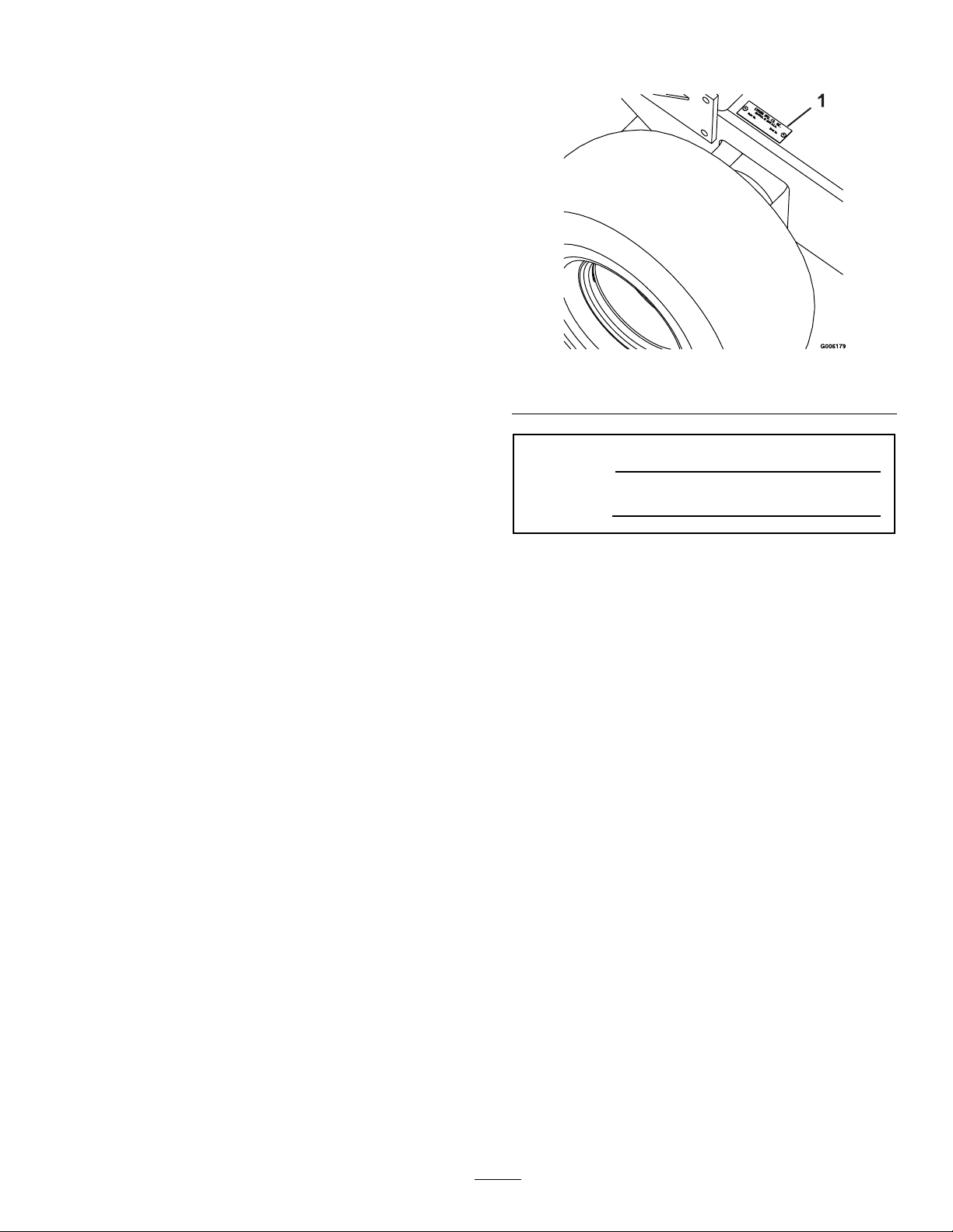
Figure1
1.Modelandserialnumberlocation
ModelNo.
Ifadditionalinformationisneeded,orshouldyou
requiretrainedmechanicservice,contactyour
authorizedExmarkequipmentdealerordistributor.
AllExmarkequipmentdealersanddistributorsare
keptinformedofthelatestmethodsofservicing
andareequippedtoprovidepromptandefcient
serviceintheeldorattheirservicestations.They
carryamplestockofservicepartsorcansecurethem
promptlyforyoufromthefactory.
AllExmarkpartsarethoroughlytestedandinspected
beforeleavingthefactory,however,attentionis
requiredonyourpartifyouaretoobtainthefullest
measureofsatisfactionandperformance.
Wheneveryouneedservice,genuineExmarkparts,
oradditionalinformation,contactanAuthorized
ServiceDealerorExmarkCustomerServiceandhave
themodelandserialnumbersofyourproductready.
Figure1identiesthelocationofthemodelandserial
numbersontheproduct.Writethenumbersinthe
spaceprovided.
SerialNo.
3
Page 4

Contents
Introduction...........................................................3
Safety.....................................................................5
SafetyAlertSymbol.........................................5
SafeOperatingPractices..................................5
SafetyandInstructionalDecals.....................10
Specications.......................................................12
ModelNumbers............................................12
Systems.........................................................12
Dimensions...................................................13
TorqueRequirements....................................14
ProductOverview................................................14
Operation.............................................................15
Controls........................................................15
Pre-Start........................................................16
OperatingInstructions..................................17
Transporting.................................................21
Maintenance.........................................................22
RecommendedMaintenanceSchedule(s)...........22
PeriodicMaintenance.......................................23
CheckEngineOilLevel.................................23
CheckBatteryCharge....................................23
CheckMowerBlades.....................................23
CheckSafetyInterlockSystem.......................24
CheckforLooseHardware............................25
ServiceAirCleaner........................................25
ChangeEngineOil........................................25
CheckHydraulicOilLevel.............................25
CheckTirePressures.....................................25
CheckConditionOfBelts..............................26
LubricateGreaseFittings...............................26
LubricateCasterWheelHubs........................26
RemoveEngineShroudsandCleanCooling
Fins...........................................................27
CheckSparkPlugs.........................................27
ChangeHydraulicSystemFilter.....................28
ThreadLockingAdhesives.............................29
MobilHTSGrease(OrFood-Grade
Anti-seize).................................................30
Copper-BasedAnti-seize..............................30
DielectricGrease...........................................30
Adjustments.....................................................30
DeckLeveling...............................................30
PumpDriveBeltTension...............................30
DeckBeltTension.........................................30
BladeDriveBeltTension..............................30
BrakeAdjustment..........................................30
SpeedControlLinkageandNeutralSafety
SwitchAdjustment....................................30
NeutralControlLinkagesAdjustment............31
HydroControlLinkageAdjustment...............31
DriveLeverLinkageAdjustment...................32
TrackingAdjustment.....................................32
HydroPumpSpringTensionSetting..............33
ElectricClutchAdjustment............................33
Cleaning...........................................................33
CleanGrassBuild-UpUnderDeck................33
WasteDisposal..............................................33
Troubleshooting...................................................35
Schematics...........................................................37
4
Page 5

Safety
Safety
SafetyAlertSymbol
ThisSafetyAlertSymbol(Figure2)isusedbothin
thismanualandonthemachinetoidentifyimportant
safetymessageswhichmustbefollowedtoavoid
accidents
Thissymbolmeans:ATTENTION!BECOME
ALERT!YOURSAFETYISINVOLVED!
Figure2
1.Safetyalertsymbol
Thesafetyalertsymbolappearsaboveinformation
whichalertsyoutounsafeactionsorsituations
andwillbefollowedbythewordDANGER,
WARNING,orCAUTION.
•Neverletchildrenoruntrainedpeopleoperate
orservicetheequipment.Localregulationsmay
restricttheageoftheoperator.
•Theowner/usercanpreventandisresponsible
foraccidentsorinjuriesoccurringtohimselfor
herself,otherpeopleorproperty.
Preparation
•Evaluatetheterraintodeterminewhataccessories
andattachmentsareneededtoproperlyand
safelyperformthejob.Onlyuseaccessoriesand
attachmentsapprovedbyExmark.
•Wearappropriateclothingincludingsafetyglasses,
substantialfootwear,longtrousers,andhearing
protection.DoNotoperatewhenbarefootor
whenwearingopensandals.Longhair,loose
clothingorjewelrymaygettangledinmoving
parts.
CAUTION
DANGER:Whitelettering/Redbackground.
Indicatesanimminentlyhazardoussituationwhich,if
notavoided,Willresultindeathorseriousinjury.
WARNING:Blacklettering/Orangebackground.
Indicatesapotentiallyhazardoussituationwhich,if
notavoided,Couldresultindeathorseriousinjury.
CAUTION:Blacklettering/Y ellowbackground.
Indicatesapotentiallyhazardoussituationwhich,if
notavoided,Mayresultinminorormoderateinjury.
Thismanualusestwootherwordstohighlight
information.Importantcallsattentiontospecial
mechanicalinformationandNoteemphasizes
generalinformationworthyofspecialattention.
SafeOperatingPractices
Training
•ReadtheOperator’sManualandothertraining
material.Iftheoperator(s)ormechanic(s)can
notreadEnglishitistheowner’sresponsibilityto
explainthismaterialtothem.
Thismachineproducessoundlevelsin
excessof85dBAattheoperator’searand
cancausehearinglossthroughextended
periodsofexposure.
Wearhearingprotectionwhenoperatingthis
machine.
•Inspecttheareawheretheequipmentistobe
usedandremoveallrocks,toys,sticks,wires,
bones,andotherforeignobjectswhichcanbe
thrownbythemachineandmaycausepersonal
injurytotheoperatororbystanders.
•Becomefamiliarwiththesafeoperationofthe
equipment,operatorcontrols,andsafetysigns.
•Alloperatorsandmechanicsshouldbetrained.
Theownerisresponsiblefortrainingtheusers.
5
Page 6

Safety
DANGER
Incertainconditionsgasolineisextremely
ammableandvaporsareexplosive.
Areorexplosionfromgasolinecanburn
you,others,andcausepropertydamage.
•Fillthefueltankoutdoorsinanopen
area,whentheengineiscold.Wipeup
anygasolinethatspills.
•Neverrellthefueltankordrainthe
machineindoorsorinsideanenclosed
trailer.
•DoNotllthefueltankcompletely
full.Addgasolinetothefueltankuntil
thelevelis1/4to1/2inch(6–13mm)
belowthebottomofthellerneck.This
emptyspaceinthetankallowsgasoline
toexpand.
•Neversmokewhenhandlinggasoline,
andstayawayfromanopenameor
wheregasolinefumesmaybeignitedby
spark.
•Storegasolineinanapprovedcontainer
andkeepitoutofthereachofchildren.
•Addfuelbeforestartingtheengine.
Neverremovethecapofthefueltankor
addfuelwhenengineisrunningorwhen
theengineishot.
•Iffuelisspilled,DoNotattempttostart
theengine.Moveawayfromtheareaof
thespillandavoidcreatinganysourceof
ignitionuntilfuelvaporshavedissipated.
•DoNotoperatewithoutentireexhaust
systeminplaceandinproperworking
condition.
DANGER
Incertainconditionsduringfueling,static
electricitycanbereleasedcausingaspark
whichcanignitegasolinevapors.Areor
explosionfromgasolinecanburnyouand
othersandcausepropertydamage.
•Alwaysplacegasolinecontainersonthe
groundawayfromyourvehiclebefore
lling.
•DoNotllgasolinecontainersinsidea
vehicleoronatruckortrailerbedbecause
interiorcarpetsorplastictruckbedliners
mayinsulatethecontainerandslowthe
lossofanystaticcharge.
•Whenpractical,removegas-powered
equipmentfromthetruckortrailerand
refueltheequipmentwithitswheelson
theground.
•Ifthisisnotpossible,thenrefuelsuch
equipmentonatruckortrailerfroma
portablecontainer,ratherthanfroma
gasolinedispensernozzle.
•Ifagasolinedispensernozzlemustbe
used,keepthenozzleincontactwiththe
rimofthefueltankorcontaineropening
atalltimesuntilfuelingiscomplete.
WARNING
Gasolineisharmfulorfatalifswallowed.
Long-termexposuretovaporshascaused
cancerinlaboratoryanimals.Failuretouse
cautionmaycauseseriousinjuryorillness.
•Avoidprolongedbreathingofvapors.
•Keepfaceawayfromnozzleandgas
tank/containeropening.
•Keepawayfromeyesandskin.
•Neversiphonbymouth.
•Checkthattheoperator’spresencecontrols,
safetyswitches,andshieldsareattachedand
functioningproperly .DoNotoperateunlessthey
arefunctioningproperly.
6
Page 7

Safety
Operation
WARNING
Operatingengineparts,especiallythe
mufer,becomeextremelyhot.Severeburns
canoccuroncontactanddebris,suchas
leaves,grass,brush,etc.cancatchre.
•Allowengineparts,especiallythemufer,
tocoolbeforetouching.
•Removeaccumulateddebrisfrommufer
andenginearea.
•Installandmaintaininworkingordera
sparkarresterbeforeusingequipment
onforest-covered,grass-covered,or
brush-coveredunimprovedland.
WARNING
Engineexhaustcontainscarbonmonoxide,
whichisanodorlessdeadlypoisonthatcan
killyou.
DoNotrunengineindoorsorinasmall
connedareawheredangerouscarbon
monoxidefumescancollect.
•Operateonlyindaylightorgoodarticiallight,
keepingawayfromholesandhiddenhazards.
•Besurealldrivesareinneutralandparkingbrake
isengagedbeforestartingengine.
•Neverraisedeckwithbladesrunning.
•Neveroperatethemowerwithdamagedguards,
shields,orcovers.Alwayshavesafetyshields,
guards,switchesandotherdevicesinplaceandin
properworkingcondition.
•Nevermowwiththedischargedeectorraised,
removedoralteredunlessthereisagrass
collectionsystemormulchkitinplaceand
workingproperly .
•DoNotchangetheenginegovernorsettingor
overspeedtheengine.
•Stopengine,waitforallmovingpartstostop,
removekeyandengageparkingbrake:
–Beforechecking,cleaningorworkingonthe
mower.
–Afterstrikingaforeignobjectorabnormal
vibrationoccurs(inspectthemowerfor
damageandmakerepairsbeforerestarting
andoperatingthemower).
–Beforeclearingblockages.
–Wheneveryouleavethemower.
•Stopengine,waitforallmovingpartstostop,and
engageparkingbrake:
–Beforerefueling.
–Beforedumpingthegrasscatcher.
–Beforemakingheightadjustments.
WARNING
Hands,feet,hair,clothing,oraccessoriescan
becomeentangledinrotatingparts.Contact
withtherotatingpartscancausetraumatic
amputationorseverelacerations.
•DoNotoperatethemachinewithout
guards,shields,andsafetydevicesin
placeandworkingproperly.
•Keephands,feet,hair,jewelry,orclothing
awayfromrotatingparts.
•DONOToperatethemowerwhenpeople,
especiallychildren,orpetsareinthearea.
•Bealert,slowdownandusecautionwhenmaking
turns.Lookbehindandtothesidebefore
changingdirections.
•Stoptheblades,slowdown,andusecautionwhen
crossingsurfacesotherthangrassandwhen
transportingthemowertoandfromtheareato
bemowed.
•Beawareofthemowerdischargepathanddirect
dischargeawayfromothers.
•DoNotoperatethemowerundertheinuence
ofalcoholordrugs.
•Useextremecarewhenloadingorunloadingthe
machineintoatrailerortruck.
•Usecarewhenapproachingblindcorners,shrubs,
trees,orotherobjectsthatmayobscurevision.
SlopeOperation
UseExtremecautionwhenmowingand/orturning
onslopesaslossoftractionand/ortip-overcould
occur.Theoperatorisresponsibleforsafeoperation
onslopes.
7
Page 8

Safety
DANGER
Operatingonwetgrassorsteepslopescan
causeslidingandlossofcontrol.Lossof
controland/orlossofoperator’sfooting
couldresultinafallwithanarmorleg
gettingunderthemowerorenginedeck
whichmayresultinseriousinjury,deathor
drowning.
•Mowacrossslopes,neverupanddown.
•DoNotmowslopeswhengrassiswet.
•DoNotmowneardrop-offsornearwater.
•DoNotmowslopesgreaterthan20
degrees.
•Reducespeedanduseextremecaution
onslopes.
•Avoidsuddenturnsorrapidspeed
changes.
•Seeinsidethebackcovertodeterminethe
approximateslopeangleoftheareatobemowed.
•Removeormarkobstaclessuchasrocks,tree
limbs,etc.fromthemowingarea.Tallgrasscan
hideobstacles.
•Watchforditches,holes,rocks,dipsandrisesthat
changetheoperatingangle,asroughterraincould
overturnthemachine.
•Avoidsuddenstartswhenmowinguphillbecause
themowermaytipbackwards.
•Beawarethatoperatingonwetgrass,acrosssteep
slopesordownhillmaycausethemowertolose
traction.Lossoftractiontothedrivewheelsmay
resultinslidingandalossofbrakingandsteering.
•Alwaysavoidsuddenstartingorstoppingona
slope.Iftireslosetraction,disengagetheblades
andproceedslowlyofftheslope.
•Followthemanufacturer’srecommendationsfor
wheelweightsorcounterweightstoimprove
stability.
•Useextremecarewithgrasscatchersor
attachments.Thesecanchangethestabilityofthe
machineandcauselossofcontrol.
MaintenanceandStorage
•Disengagedrives,lowerimplement,setparking
brake,stopengineandremovekeyordisconnect
sparkplugwire.Waitforallmovementtostop
beforeadjusting,cleaningorrepairing.
•Keepengineandengineareafreefrom
accumulationofgrass,leaves,excessivegrease
oroil,andotherdebriswhichcanaccumulate
intheseareas.Thesematerialscanbecome
combustibleandmayresultinare.
•Letenginecoolbeforestoringanddonotstore
nearameoranyenclosedareawhereopenpilot
lightsorheatappliancesarepresent.
•Shutofffuelwhilestoringortransporting.Do
Notstorefuelnearamesordrainindoors.
•Parkmachineonlevelground.Neverallow
untrainedpersonneltoservicemachine.
•Usejackstandstosupportcomponentswhen
required.
•Carefullyreleasepressurefromcomponentswith
storedenergy.
•Disconnectbatteryorremovesparkplugwire
beforemakinganyrepairs.Disconnectthe
negativeterminalrstandthepositivelast.
Reconnectpositiverstandnegativelast.
•Usecarewhencheckingblades.Wraptheblade(s)
orweargloves,andusecautionwhenservicing
them.Onlyreplacedamagedblades.Never
straightenorweldthem.
•Keephandsandfeetawayfrommovingparts.
Ifpossible,donotmakeadjustmentswiththe
enginerunning.
•Chargebatteriesinanopenwellventilatedarea,
awayfromsparkandames.Unplugcharger
beforeconnectingordisconnectingfrombattery.
Wearprotectiveclothinganduseinsulatedtools.
•Keepallguards,shieldsandallsafetydevicesin
placeandinsafeworkingcondition.
•Checkallboltsfrequentlytomaintainproper
tightness.
•Frequentlycheckforwornordeteriorating
componentsthatcouldcreateahazard.
•Allreplacementpartsmustbethesameas
orequivalenttothepartssuppliedasoriginal
equipment.
8
Page 9

WARNING
Hydraulicuidescapingunderpressure
canpenetrateskinandcauseinjury.Fluid
accidentallyinjectedintotheskinmustbe
surgicallyremovedwithinafewhoursbya
doctorfamiliarwiththisformofinjuryor
gangrenemayresult.
•Makesureallhydraulicuidhoses
andlinesareingoodconditionand
allhydraulicconnectionsandttings
aretightbeforeapplyingpressureto
hydraulicsystem.
•Keepbodyandhandsawayfrompinhole
leaksornozzlesthatejecthighpressure
hydraulicuid.
•Usecardboardorpaper,notyourhands,
tondhydraulicleaks.
Safety
•Safelyrelieveallpressureinthehydraulic
systembyplacingthemotioncontrol
leversinneutralandshuttingoffthe
enginebeforeperforminganyworkon
thehydraulicsystem.
9
Page 10
Safety
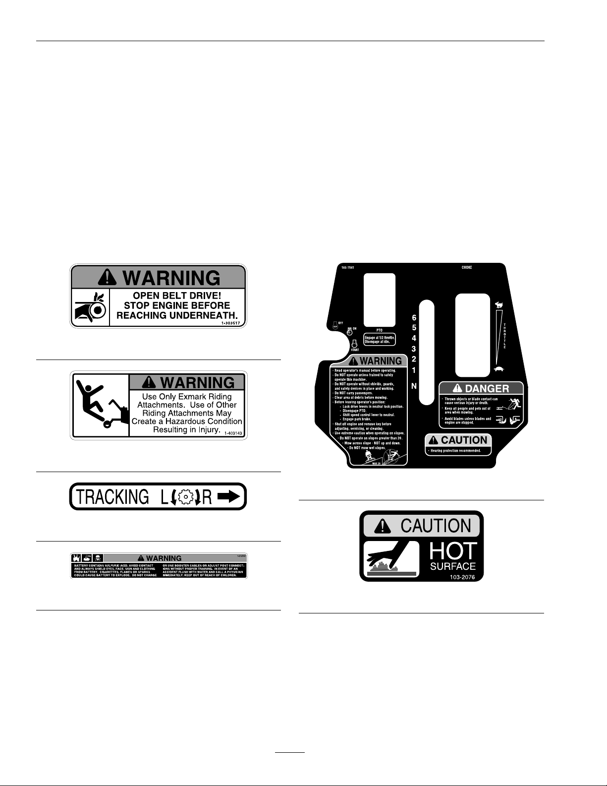
SafetyandInstructionalDecals
•Keepallsafetysignslegible.Removeallgrease,
dirtanddebrisfromsafetysignsandinstructional
labels.
•Replaceallworn,damaged,ormissingsafety
signs.
•Whenreplacementcomponentsareinstalled,be
surethatcurrentsafetysignsareafxedtothe
replacedcomponents.
•Ifanattachmentoraccessoryhasbeeninstalled,
makesurecurrentsafetysignsarevisible.
1-303517
•Newsafetysignsmaybeobtainedfrom
yourauthorizedExmarkequipmentdealeror
distributororfromExmarkMfg.Co.Inc.
•Safetysignsmaybeafxedbypeelingoffthe
backingtoexposetheadhesivesurface.Apply
onlytoaclean,drysurface.Smoothtoremove
anyairbubbles.
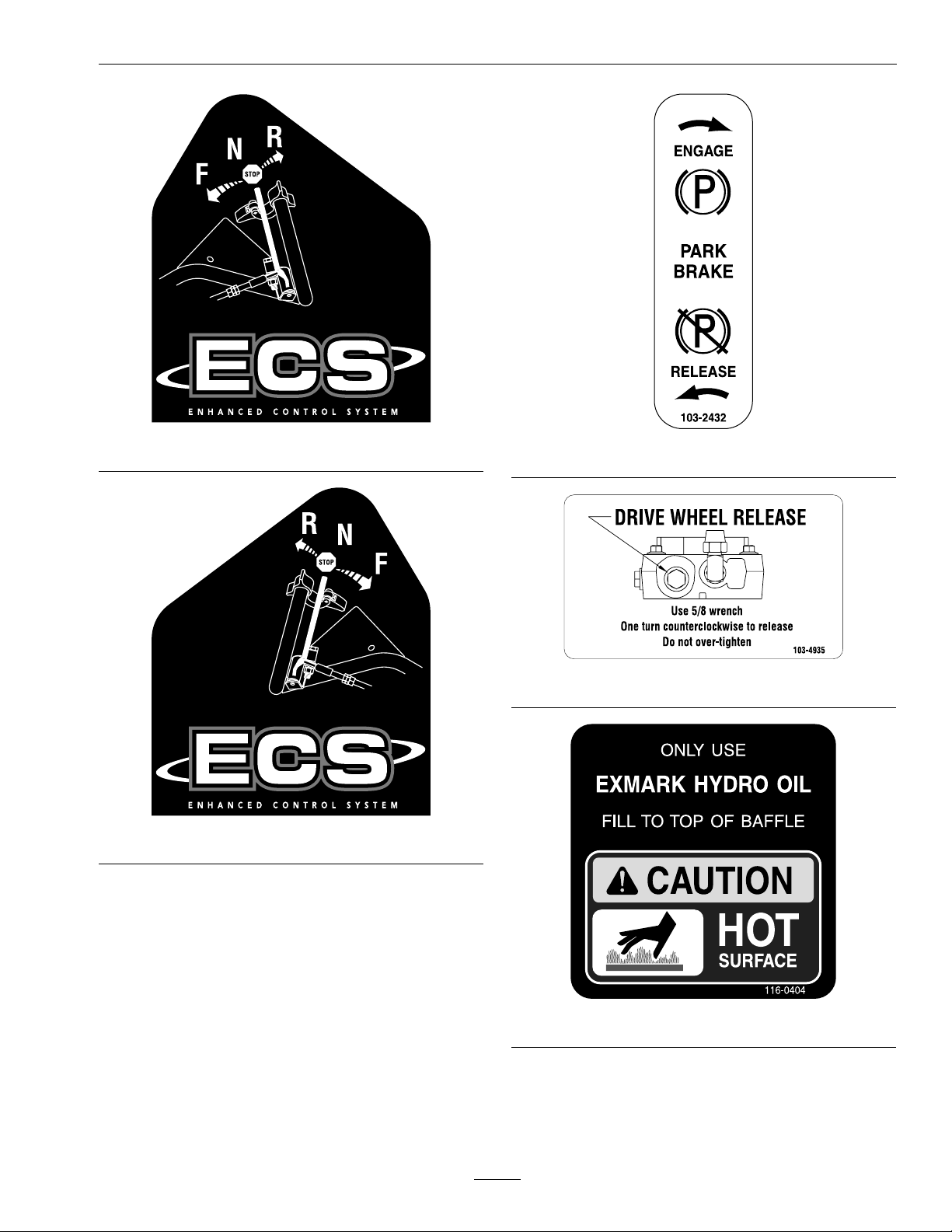
•Familiarizeyourselfwiththefollowingsafetysigns
andinstructionlabels.Theyarecriticaltothesafe
operationofyourExmarkcommercialmower.
1-403143
103–1541
1-413214
1-513747
103–2076
10
Page 11
Safety
103–2242
103–2243
103-2432
103-4935
116-0404
11
Page 12

Specications
Specications
ModelNumbers
SerialNos:790,000andHigher
TT20KCE,TT23KAE
Systems
Engine
•EngineSpecications:SeeyourEngineOwner’s
Manual
•RPM:FullSpeed:3600(NoLoad)
FuelSystem
•Capacity:5.0gal.(18.9L)
•TypeofFuel:Regularunleadedgasoline,87
octaneorhigher.
•FuelFilter:ReplaceableIn-line
•FuelShut-OffValve:1/4turnincrements
ElectricalSystem
•ChargingSystem:FlywheelAlternator
•ChargingCapacity:15amps
•BatteryType:BCIGroupU1235amps0°F
•BatteryVoltage:12Volt
•Polarity:NegativeGround
•Fuses:Twobladetype,20amptochargingcircuit;
20amptoelectricclutch
OperatorControls
SteeringControl:Fingertipdrivecontrollevers
provideindependentspeedcontrol,brakingand
neutraltoeachdrivewheelformovingforwardor
reverse,stopping,andpowerturning.
Transmission
•TwoHydroGearvariabledisplacementpiston
pumpsindependentlycoupledtotwohigh
efciencyParkerwheeldrivemotors.
•HydraulicOil:UseExmarkPremiumHydroOil.
•HydraulicOilCapacity:2.4qt.(2.2L)
•HydraulicFilterisreplaceablecartridgetype.
P/N109–4180:25microns,10psibypass
(Summeruseabove32°F(0°C))
P/N1–523541:40microns,18psibypass(Winter
usebelow32°F(0°C))
•Speeds:
–0-6.75mph(10.9km/hr)forward.
–0-2.25mph(3.6km/hr)reverse.
•Drivewheelreleasevalvesallowmachinetobe
movedwhenengineisnotrunning.
SafetyInterlockSystem:
•OperatormusthaveOPC(OperatorPresence
Control)leversheldincontactwithhandle
grips,speedcontrolleverinneutral,andPTO
disengagedtostartengine.ReleaseofOPClevers
willcausetheenginetostopifspeedcontrollever
isnotinneutraland/orPTOisengaged.
•Parkbrakemustbeengagedtomovespeed
controloutofneutralorenginewillkill.
WheelDriveSystem
DrivewheelsaredirectcoupledtoParkerwheeldrive
motorswith1inch(25.4mm)taperedshaft.
12
Page 13

Specications
Tires&Wheels
DriveFrontCaster
Pneumatic
(Air-Filled)
AllSerial
Nos.
Quantity
Tread
Size18x8.50-811x4.00-511x4.00-5
PlyRating
Pressure
222
TurfMasterSmoothSmooth
44
14psi(96
kPa)
Pneumatic
(Air-Filled)
SN599,999
&Lower
16psi(110
kPa)
CuttingDeck
•ModelNumbers:
–FMD524
–FMD604
•CuttingWidth:
•CuttingHeightAdjustment:
Adjustsfrom11/2inches(3.8cm)to41/2
inches(11.4cm)in1/2inch(1.3cm)increments.
SemiPneumatic
SN600,000
&Higher
•MulchingKit:Optional
•Bagger:Optional
Dimensions
OverallWidth:
52inchDeck60inchDeck
DeectorUp53.4inches
(135.6cm)
DeectorDown64.8inches
(164.6cm)
OverallLength:
52inchDeck60inchDeck
83.4inches(211.8cm)83.4inches(211.8cm)
61.4inches
(156.0cm)
73.0inches
(185.4cm)
–52inch(132.1cm)
–60inch(152.4cm)
•Discharge:Side
•BladeSize:(3ea.)
–52inchDeck:18.00inches(45.7cm)
–60inchDeck:20.50inches(52.1cm)
•BladeSpindles:Solidsteelspindleswith13/4
inch(4.45cm)I.D .bearings.
•DeckDrive:
–Electricclutchmountedonengineshaft.
–Bladesdrivenbytwobelts(w/self-tensioning
idlers).
•Deck:
Fulloatingdeckisattachedtoout-frontsupport
frame,removableforservice.Sixanti-scalprollers
providemaximumturfprotection.Deckdesign
allowsforbagging,mulchingorsidedischarge.
•DeckDepth:
–52inchDeck:5.5inches(14.0cm)
OverallHeight:
52inchDeck60inchDeck
45inches(114.3cm)45inches(114.3cm)
TreadWidth:(OutsidetoOutsideof
Tires,Widthwise)
52inchDeck60inchDeck
45.8inches(116.3cm)45.8inches(116.3cm)
WheelBase:(CenterofCasterTireto
CenterofDriveTire)
52inchDeck60inchDeck
43.3inches(110.0cm)43.3inches(110.0cm)
CurbWeight:
52inchDeck60inchDeck
720lb(327kg)760lb(345kg)
–60inchDeck:5.5inches(14.0cm)
13
Page 14
ProductOverview
TorqueRequirements
BoltLocation
CutterHousingSpindle
Nut
BladeMountingBolt
(lubricatewithanti-seize)
EngineDeck/Mower
DeckSupportMount
Bolts
Type1Hardware
–Anti-ScalpRoller
WhizlockNutSeeFigure9
Type2
Hardware–Anti-Scalp
RollerNylocNutSee
Figure9
Type2&3Hardware
–Anti-ScalpRollerHex
CapscrewSeeFigure9
Type3
Hardware–Anti-Scalp
RollerFlangedNylocNut
SeeFigure9
Torque
140–145ft-lb(190–197
N-m)
55-60ft-lb(75-81N-m)
30-35ft-lb(41-47N-m)
40-45ft-lb(54-61N-m)
30-35ft-lb(41-47N-m)
50-55ft-lb(68-75N-m)
30-35ft-lb(41-47N-m)
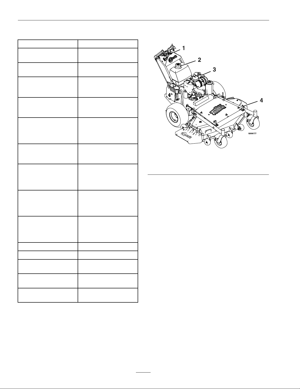
ProductOverview
Figure3
1.Controls
2.FuelCap4.Height-of-CutPins
3.ParkBrakeLever
Type4
Hardware–Anti-Scalp
RollerWhizlockNutSee
Figure9
Type4
Hardware–Anti-Scalp
RollerNylocNutSee
Figure9
EngineMountingBolts
WheelLugNuts
WheelHubSlottedNutsminimum100ft-lb(136
ClutchRetainingBolt
(securedwiththreadlocker)
WheelMotorMounting
Bolts
30-35ft-lb(41-47N-m)
30-35ft-lb(41-47N-m)
15-20ft-lb(20-27N-m)
90-95ft-lb(122-129N-m)
N-m)
55-60ft-lb(75-81N-m)
30-35ft-lb(41-47N-m)
14
Page 15

Operation
Operation
Note:Determinetheleftandrightsidesofthe
machinefromthenormaloperatingposition.
Controls
OperatorPresenceControl(OPC)
Levers
Locatedontheupperhandleassemblydirectlyabove
thehandlegrips.
Whentheseleversaredepressed,theOPCsystem
sensesthattheoperatorisinthenormaloperator’s
position.Whentheleversarereleased,theOPC
systemsensesthattheoperatorhasmovedfromthe
normaloperatingpositionandwillkilltheengineif
eitherthespeedcontrolleverisnotintheneutral
positionorthePTOisengaged.
asshowninFigure4,andthedriveleversarereleased,
thedrivewheelsareengagedintheforwarddirection.
Squeezingthelefthandand/orrighthandlever
causesthelefthandand/orrighthanddrivewheel
respectivelytoslowdown,stop,orreverse,depending
onhowfareachdriveleveris“squeezed”.Squeezing
thedriveleversbeyondtheneutralpositioncauses
thedrivewheelstoengageinthereversedirection
regardlessofthepositionoftheneutrallocklatches
andthespeedcontrollever.
NeutralLockLatches
Locatedontheupperhandleassemblyontheends
ofthehandlegrips.
Theselatchesallowtheoperatortolockthedrive
leversina“neutral”positionwherethedrivewheels
arenotengagedineitheraforwardorreverse
direction.
ChokeControl
1.OPCLever
2.Rotateneutrallocklatch
downwardforneutral
lockposition
DriveLevers
Figure4
3.NeutralLockLatch
4.DriveLeverinneutral
position
Locatedonthecontrolconsolefrontrighthandside.
Chokeisusedtoaidinstartingacoldengine.The
chokecontrolispulledouttobeinthe“ON”position
andpushedintobeinthe“OFF”position.DoNot
runawarmenginewithchokeinthe“ON”position.
ThrottleControl
Locatedonthecontrolconsole’srightside.
Thethrottleisusedtocontrolenginespeed.Moving
thethrottlecontrolforwardwillincreaseengine
speedandmovingittotherearwilldecreaseengine
speed.Movingthethrottleforwardintothedetent
isfullposition.
SpeedControlLever
Locatedinmiddleofcontrolconsole.
Thespeedcontrollevercontrolsthemaximum
forwardspeedandisinnitelyvariablefromneutral
0–6.75mph(10.9km/hr).
Locatedoneachsideoftheupperhandleassembly
aheadofandbelowthehandlegrips.
Theseleversindividuallycontrolthespeedand
directionofeachdrivewheel.Whenthespeedcontrol
leverismovedoutoftheneutralpositionandthe
neutrallocklatchesaremovedintothedriveposition,
Parkbrakemustbedisengagedtomovespeedcontrol
outofneutralorenginewillkill.
BrakeLever
Locatedontheleftsideoftheunitabovethe
hydraulictank.
15
Page 16

Operation
Thebrakeleverengagestheparkbrakeonthedrive
wheels.
Pulltheleverupandrearwardtoengagethebrake.
Pushtheleverforwardanddowntodisengagethe
brake.
Whenparkingonasteepslope,thewheelsmustbe
chockedorblockedinadditiontothebrakebeing
engaged.Theunitmustbetieddownandbrake
engagedwhentransporting.
Parkbrakemustbedisengagedtomovespeedcontrol
outofneutralorenginewillkill.
IgnitionSwitch
Locatedontheleftsideofthecontrolconsole.
Theignitionswitchisusedtostartandstopthe
engine.Theignitionswitchhasthreepositions,
“Off”,“On”and“Start”.Insertkeyintoswitch
androtateclockwisetothe“On”position.Rotate
clockwisetothenextpositiontoengagethestarter
(keymustbeheldagainstspringpressureinthis
position).Operatormusthavespeedcontrolleverin
neutral,OPCleversdepressedandPTOdisengaged
tostartengine.Whenenginestarts,releasekey.
HourMeter
Locatedonthefrontlefthandsideofconsolejust
abovethePTOswitch.
DriveWheelReleaseValves
Locatedontheleftrearcornerofthehydrostatic
pumps.
Drivewheelreleasevalvesareusedtoreleasethe
hydro-staticdrivesystemtoallowthemachinetobe
movedbyhandwithouttheenginerunning.
Witha5/8wrench,turnbothvalvesoneturn
counterclockwisetoreleasethedrivesystem.
Turnclockwisetoresetthedrivesystem.DoNot
overtighten.
TrackingAdjustmentKnob
Locatedontheright-handsideoftherearofthefuel
tanksupport.
Theknobcanbeadjustedsothatmachinewill
“track”straightaheadwiththedriveleversreleased.
PTOEngagementSwitch
Switchislocatedonleftsideofcontrolconsole.
Theswitchmustbepulledouttothe“Rotate”
positiontoengagetheblades.Theswitchispushed
intothe“Stop”positiontostoptheblades.Operator
musthaveoperatorpresencecontrolleversdepressed
whenPTOisengagedorenginewillstop.
Thehourmeterisconnectedtoapressureswitch
installedintheengineblockanditrecordsthe
numberofhoursthattheenginehasrun.Ifignition
switchisleftonwithoutenginerunning,hourmeter
willnotrun.
Note:Thisswitchisnotalowoilsensorandwillnot
alerttheoperatoriftheengineoilislow .
FuelShut-OffValve
Locatedinthefuellinemidwaybetweenthetank
andengine.
Thefuelshut-offvalveisusedtoshutoffthe
owoffuelwhenparkinginsideabuilding,during
transportationtoandfromthejobsites,andwhen
themachinewillnotbeusedforafewdays.
Rotatevalve1/4turnclockwisetoshutfueloff.
Rotatevalve1/4turncounterclockwisetoturnfuel
on.
Pre-Start
Fillfueltanks.Forbestresultsuseonlyclean,fresh
regulargradeunleadedgasolinewithanoctanerating
of87orhigher.Regulargradeleadedgasolinemay
alsobeused;however,combustionchamberand
cylinderheadwillrequiremorefrequentservice.See
EngineOwner’sManual.
DoNotaddoiltogasoline.
DoNotoverllfueltank.Neverllthefueltankso
thatthefuellevelrisesabovealevelthatis1/2inch
belowthebottomofthellernecktoallowforfuel
expansionandpreventfuelspillage.
Makesureyouunderstandthecontrols,their
locations,theirfunctions,andtheirsafety
requirements.
RefertotheMaintenancesectionandperformallthe
necessaryinspectionandmaintenancesteps.
16
Page 17

Operation
OperatingInstructions
OpentheFuelShut-OffValve
Rotatethevalve1/4turncounterclockwisetoturn
fuelon.
StartingtheEngine
1.Onacoldengine,placethethrottlemidway
betweenthe“Slow”and“Fast”positionsand
placethechokeinthe“On”position.Onawarm
engine,placethethrottlelevermidwaybetween
“Slow”and“Fast”positionsandleavethechoke
inthe“Off”position.
2.Turnignitionswitchto“Start”position.Release
theswitchassoonastheenginestarts.
3.Onacoldengine,graduallyreturnchoketothe
“Off”positionafterenginestartsandwarmsup.
Important:Donotcranktheengine
continuouslyformorethantensecondsat
atime.Iftheenginedoesnotstart,allowa
60secondstartercool-downperiodbetween
startingattempts.Failuretofollowthese
guidelinescanburnoutthestartermotor.
DANGER
Anuncovereddischargeopeningwillallow
objectstobethrowninanoperator’sor
bystander’sdirection.Also,contactwiththe
bladecouldoccur.Thrownobjectsorblade
contactcancauseseriousinjuryordeath.
Neveroperatethemowerwiththedischarge
deectorraised,removed,oralteredunless
thereisagrasscollectionsystemormulch
kitinplaceandworkingproperly.
ThePTOswitchengagesthecuttingblades.Besure
thatallpersonsareclearofmowerdeckanddischarge
areabeforeengagingthePTO .
1.Setthrottleto“MIDW AY”position.
2.PullthePTOswitchoutwardtothe“ROTATE”
positiontoengagetheblades.
3.Placethethrottleinthe“FAST”positiontobegin
mowing.
DisengagingthePTO
1.Setthrottleto“MIDW AY”position.
Note:Itishelpfultohavetheleftandright
neutrallocklatcheslockedinneutralwhen
startingtheengine.RefertoNeutralLock
LatchessectioninControls.
PTOEngagement
DANGER
Therotatingbladesunderthemowerdeck
aredangerous.Bladecontactcancause
seriousinjuryorkillyou.
DoNotputhandsorfeetunderthemower
ormowerdeckwhenthebladesareengaged.
2.Pushinontheswitchtothe“STOP”position
todisengagetheblades.
StoppingtheEngine
1.Bringtheunittoafullstop.
2.Lockdriveleversinneutral.
3.DisengagethePTO.
4.Movespeedcontrollevertoneutral.
5.Engagetheparkingbrake.
6.Placethethrottlemidwaybetweenthe“SLOW”
and“FAST”positions.
7.Allowtheenginetorunforaminimumof15
seconds,thenturntheignitionswitchtothe
“OFF”positiontostoptheengine.
8.Removethekeytopreventchildrenorother
unauthorizedpersonsfromstartingengine.
9.Closethefuelshut-offvalvewhenthemachine
willnotbeinuseforafewdays,when
transporting,orwhentheunitisparkedinside
abuilding.
17
Page 18

Operation
DrivingtheMachine
DriveLever/NeutralLockLatchOperation
Tolockthedriveleversin“neutrallock”,squeezethe
driveleverstothe“neutral”position(DoNotsqueeze
thedriveleversallthewaybackasthiswillcausethe
drivewheelstogointofullreversedirection).See
Figure5position1.Placethumbsontheinnerlobe
oftheneutrallocklatchesandrotatethemunder
thedriveleversintothe“neutrallock”position.See
Figure5position2.Releasethedrivelevers.
CAUTION
Iftheneutrallocklatchesarenotcompletely
engagedthedriveleverscouldunexpectedly
slipintotheforwarddriveposition.Ifthe
driveleversslipintothedrivepositionthe
unitcouldlurchforwardandcauseinjuryor
propertydamage.
Besurethedriveleversarepasttherollerand
securelyseatedatthebottomoftheneutral
locklatches.
Toplacethedriveleversinthe“forward”position,
slightlysqueezethedriveleverswhileplacingthumbs
ontheouterthumblobeoftheneutrallocklatches
(ortheindexngeronthefrontlobe)androtatethem
fromunderthedrivelevers.Slowlyandcarefully
releasethedrivelevers.SeeFigure5position3.
Toplacethedriveleversinthe“reverse”position,
squeezethedriveleverspasttheneutralposition.See
Figure5position4.
Figure5
1.DriveLeverinneutral
position
2.DriveLeverlockedin
neutralposition
3.DriveLeverinforward
position
4.DriveLeverinreverse
position
DrivingForward
1.Releasetheparkingbrake.
2.Withdriveleverslockedin“neutral”,shiftspeed
controllevertodesiredforwardspeed.
3.Slowlysqueezeandholdbothdriveleversin
theneutralpositionandrotatebothneutrallock
latchesfromtheneutrallockpositiontothe
forwardposition.
Note:DoNotsqueezebothdriveleversallthe
wayback.Thiswillcausethedrivewheelsto
engageinthereversedirection.
4.Tomoveforwardinastraightline,smoothly
releasebothdriveleverstoengagedrivewheels.
Toturnleftorright,squeezetherighthanddrive
levertoturnrightandthelefthanddrivelever
toturnleft.
Tomakea“zeroturn”,squeezeeithertheleft
handortherighthanddriveleverbackintothe
reversepositionwhiletheoppositedriveleverisin
aforwardpositionatanequalbutoppositespeed.
Note:Forsmoothoperationofthismachine,
avoidquick,jerkymovementsofthedrivelevers.
Movethedriveleverssmoothlyanddeliberately.
Tostop,squeezedriveleversbacktothe“neutral”
position.Movetheneutrallocklatchesintothe
“neutrallock”positionandreleasedrivelevers.
Movethespeedcontrollevertotheneutral
position.
18
Page 19

DrivinginReverse
Tomoverearwardinastraightline,squeezedrive
leversintothereverseposition.
Toturnleftorright,squeezetherighthanddrivelever
toturnleftandthelefthanddrivelevertoturnright.
Tomakea“zeroturn”,squeezeeitherthelefthand
ortherighthanddriveleverbackintothereverse
positionwhiletheoppositedriveleverisinaforward
positionatanequalbutoppositespeed.
Note:Forsmoothoperationofthismachine,avoid
quick,jerkymovementsofthedrivelevers.Movethe
driveleverssmoothlyanddeliberately.
Tostop,squeezedriveleversbacktothe“neutral”
position.Movetheneutrallocklatchesintothe
“neutrallock”positionandreleasedrivelevers.Move
thespeedcontrollevertotheneutralposition.
AdjustingtheCuttingHeight
WARNING
Whenthetwofrontsupportrodhairpinsare
removedfromthemowerdeck,theweightof
thetractorsectionmaycausethefrontframe
oftheunittorisesuddenly.Iftheunitrises
suddenly,injurymayoccur.
Securelyholddownthefrontoftheunitwhen
thefrontsupportrodhairpinsareremoved.
Operation
Figure6
1.Decksupportpin
B.ThetirepressuresaresetasdirectedinCheck
TirePressuresintheMaintenancesection.
C.Thelengthofthereardecksupportlink
assembliesaverage6.89inches(approximately
67/8inches)(175.01mm)fromthecenterof
theballjointtothecenterofthefarthesthole.
SeeFigure7.
Note:Allfourpinsmustequallysupportthe
weightofthedeck.Adjustmentinthelength
ofthereardecksupportassembliesmaybe
necessary.Ifonesideislongerthan6.89
inches(approximately67/8inches)(175.01
mm),thantheoppositesidemustbeshorter
bythesameamount.
2.CuttingHeight
Thecuttingheightofthemowerdeckisadjusted
from11/2to41/2inches(3.81cmto11.4cm)in
1/2inchincrements.
1.Stopthemachineandmovethedriveleverstothe
neutrallockedposition.
2.DisengagethePTO.
3.Engagetheparkbrake.
4.Stoptheengine,removethekeyandwaitforall
movingpartstostop.
5.Installhairpinclipsintheholesforthedesired
cuttingheight.SeeFigure6.
Important:T omaintaincorrectcutting
heightandrake,checkthefollowingfor
properadjustment.
A.Thefrontandrearhairpinsareinthesame
holeswiththeproperspacersunderthehair
pins.SeeFigure6.
19
Page 20

Operation
Figure8
Forcuttingheightsabove3.5inches(38mm)usethe
bottomhole.Therollerswillstillbeeffectiveagainst
scalping.
Figure7
LeftHandSideShown
AdjustingtheAnti-ScalpRollers
Itisrecommendedtochangetheanti-scalproller
position,whentheheightofcuthaschanged.
1.Stopthemachineandmovethedriveleversto
theneutrallockposition.
2.DisengagethePTO.
3.Engagetheparkbrake.
4.Stoptheengine,removethekeyandwaitforall
movingpartstostop.
5.Afteradjustingtheheightofcut,adjustthe
anti-scalprollersbyremovingthespringdisc
washerandbolt(seestep7).
6.Adjustanti-scalprollersforNormalOperating
Conditions.Placerollersinoneofthepositions
showninFigure8.Rollerswillmaintain3/4
inches(19mm)clearancetothegroundto
minimizegougingandrollerwearordamage.
Note:ForMaximumDeckFlotation,place
rollersoneholepositionlower.Rollersshould
maintain1/4inch(6.35mm)clearancetoground.
DoNotadjustrollerstosupportthedeck.Be
surerollerboltsareinstalledwiththespringdisc
washerbetweenheadoftheboltandmounting
bracket.
1.Anti-scalproller
mountingbracket
2.Cuttingheight
7.Fourtypesofanti-scalprollerassembliesare
available.SeeFigure9todeterminewhich
assemblyhasbeeninstalledontheunit.Torque
hardwareasspecied,orlossofrollermayresult.
SeeFigure9.
Figure9
Frontleftanti-scalpbracketshown
1.Type1hardware
2.Type2hardware
3.Type3hardware
4.Type4hardware
5.(Type1)3/8–16x4hexscrew
6.(Type2&3)3/8–24x2hexscrew—T orqueto50–55
ft-lb(68–75N-m)
7.(Type4)3/8whizlocknut—T orqueto30–35ft-lb
(41–47N-m)
8.Springdiscwasher(conetowardsbolthead)
9.(Type1)3/8whizlocknutandheavyatwasher—
Torqueto40–45ft-lb(54–61N-m)
10.(Type2)3/8nylocnutandheavyatwasher—T orque
to30–35ft-lb(41–47N-m)
11.(T ype3)3/8angednylocnutwithoutwasher—T orque
to30–35ft-lb(41–47N-m)
12.(Type4)3/8nylocnut—T orqueto30–35ft-lb
(41–47N-m).
20
Page 21

Transporting
TransportingaUnit
WARNING
Loadingthemowerontoatrailerwithout
strongenoughorproperlysupportedramps
couldbedangerous.Therampscould
collapsecausingtheunittofall,whichcould
causeinjury.
•Useproperrampsthataresecuredtothe
truckortrailer.
•Keepfeetandlegsoutfromunderthe
unitwhenloadingandunloading.
•Ifnecessary,useassistancewhenloading .
Besurethefuelshut-offvalveisclosed.
Operation
Useaheavydutytrailertotransportthemachine.
Engageneutrallocklatchesandparkbrake,then
blockwheels.
Securelyfastenthemachinetothetrailerwithstraps,
chains,cables,orropes.
DoNotrelysolelyontheparkingbraketoholdthe
machineonthetrailer.
Besurethatthetrailerhasallnecessarylightingand
markingasrequiredbylawanduseasafetychain.
21
Page 22

Maintenance
Maintenance
Note:Determinetheleftandrightsidesofthemachinefromthenormaloperatingposition.
WARNING
Whilemaintenanceoradjustmentsarebeing
made,someonecouldstarttheengine.
Accidentalstartingoftheenginecould
seriouslyinjureyouorotherbystanders.
Removethekeyfromtheignitionswitch,
engageparkingbrake,andpullthewire(s)
offthesparkplug(s)beforeyoudoany
maintenance.Alsopushthewire(s)aside
soitdoesnotaccidentallycontactthespark
plug(s).
RecommendedMaintenanceSchedule(s)
MaintenanceService
Interval
Aftertherst5hours
Aftertherst250hours
Beforeeachuseordaily
MaintenanceProcedure
•Changetheengineoil.
•Changethehydrauliclter.
•Checktheengineoillevel.
•Checkthemowerblades.
•Checkthesafetyinterlocksystem.
•Checkforloosehardware.
•Cleanthegrassbuild-upfromunderthedeck.
WARNING
Theenginecanbecomeveryhot.Touching
ahotenginecancausesevereburns.
Allowtheenginetocoolcompletelybefore
serviceormakingrepairsaroundtheengine
area.
Every40hours
Every50hours
Every80hours
Every100hours
Every160hours
Every500hours
Every600hours
•Checkthehydraulicoillevel.
•Checkthetirepressures.
•Checktheconditionofthebelts.
•Greasethehydrocontrolarmsupportbushings.
•Servicetheaircleaner.(Mayneedmoreoftenundersevereconditions.SeetheEngine
manualforadditionalinformation.)
•Removeengineshroudsandcleancoolingns.
•Changetheengineoil.(Mayneedmoreoftenundersevereconditions.)
•Checkthesparkplugs.
•Changethehydrauliclter(Every250hours/yearlyifusingMobil115W50)
•Replacetheaircleanerelements.(Mayneedmoreoftenundersevereconditions.Seethe
Enginemanualforadditionalinformation.)
Monthly
Yearly
•Checkthebatterycharge.
•Greasethefrontcasterwheelhubs.
•Greasefrontcasterpivots.
•Greasetheidlerpivots(MowerDeck).
•Greasetheidlerpivot(PumpDrive).
•Lubricatethecasterwheelhubs.
22
Page 23

Maintenance
PeriodicMaintenance
CheckEngineOilLevel
ServiceInterval:Beforeeachuseordaily
1.Stopengineandwaitforallmovingpartstostop.
Makesureunitisonalevelsurface.
2.Checkwithenginecold.
3.Cleanareaarounddipstick.Removedipstickand
wipeoiloff.Reinsertthedipstickandpushitall
thewaydownintothetube.DoNotscrewinto
place.Removethedipstickandreadtheoillevel.
4.Iftheoillevelislow ,wipeofftheareaaroundthe
oilllcap,removecapandlltothe“FULL”
markonthedipstick.Useoilasspeciedin
EngineOwner’ sManual.DoNotoverll.
Important:DoNotoperatetheenginewiththe
oillevelbelowthe“LOW”(or“ADD”)markon
thedipstick,oroverthe“FULL”mark.
CheckBatteryCharge
ServiceInterval:Monthly
timeintervaltobringthechargeuptoafullcharge
of12.6voltsorgreater.
Important:Makesurethenegativebattery
cablesaredisconnectedandthebatterycharger
usedforchargingthebatteryhasanoutputof
16voltsand7ampsorlesstoavoiddamaging
thebattery(seechartforrecommendedcharger
settings).
Voltage
Reading
12.6or
greater
12.4–12.675–100%
12.2–12.450–75%
12.0–12.225–50%
11.7–12.00–25%
11.7orless
Percent
Charge
100%
0%
Maximum
Charger
Settings
16volts/7
amps
16volts/7
amps
16volts/7
amps
14.4volts/4
amps
14.4volts/4
amps
14.4volts/2
amps
Charging
Interval
No
Charging
Required
30Minutes
1Hour
2Hours
3Hours
6Hoursor
More
WARNING
CALIFORNIA
Proposition65Warning
Batteryposts,terminals,andrelated
accessoriescontainleadandlead
compounds,chemicalsknowntotheStateof
Californiatocausecancerandreproductive
harm.Washhandsafterhandling.
Allowingbatteriestostandforanextendedperiodof
timewithoutrechargingthemwillresultinreduced
performanceandservicelife.Topreserveoptimum
batteryperformanceandlife,rechargebatteriesin
storagewhentheopencircuitvoltagedropsto12.4
volts.
Note:Topreventdamageduetofreezing,battery
shouldbefullychargedbeforeputtingawayfor
winterstorage.
Checkthevoltageofthebatterywithadigital
voltmeter.Locatethevoltagereadingofthebatteryin
thetableandchargethebatteryfortherecommended
CheckMowerBlades
ServiceInterval:Beforeeachuseordaily
1.Stopengine,waitforallmovingpartstostop,and
removekey.Engageparkingbrake.
2.Liftdeckandsecureinraisedpositionasstated
intheCleanGrassBuild-UpUnderDeck
procedure.
3.Inspectbladesandsharpenorreplaceasrequired.
4.Reinstallblades(iftheywereremoved)inthe
followingorder:
A.Installbushingthroughbladewithbushing
angeonbottom(grass)sideofblade.
23
Page 24

Maintenance
Figure10
1.Installbushinginbladepriortoinstallingbushingin
spindle.
B.Installbushing/bladecombointospindle.
WARNING
Incorrectinstallationofthebladeor
componentsusedtoretainthebladecan
bedangerous.Failuretousealloriginal
componentsandassembledasshowncould
allowabladeorbladecomponenttobe
thrownoutfromunderthedeckresultingin
seriouspersonalinjuryordeath.
AlwaysinstalltheoriginalExmarkblades,
bladebushings,andbladeboltsasshown.
CheckSafetyInterlock
System
ServiceInterval:Beforeeachuseordaily
1.Checkstartingcircuit.Startershouldcrankwith:
OperatorPresenceControlleversdepressed,
speedcontrolleverinneutral,andPTO
disengaged.
Figure11
1.Usewrenchherefor
bladeinstallation.This
nuthasbeentorquedto
90–110ft-lb(122–149
N-m)
2.Torqueto55-60ft-lb
(75-81N-m)Apply
lubricanttothreads
asneededtoprevent
seizing.Copper-based
anti-seizepreferable.
Greaseacceptable
substitute.
C.Applylubricanttothreadsofbladeboltas
neededtopreventseizing.Copper-based
anti-seizepreferable.Greaseacceptable
substitute.Installbladeboltngertight.Place
wrenchonthetopspindlenutthentorquethe
bladeboltsto55-60ft-lb(75-81N-m).
TrytostarttheenginewithOPClevers
disengaged,speedcontrolleverinneutraland
PTOdisengaged-startermustnotcrank.
Trytostartwith,OPCleversdepressed,speed
controlleverinanyspeedbutneutralandPTO
disengaged-startermustnotcrank.
TrytostartwithOPCleversdepressed,
speedcontrolleverinneutralandPTO
engaged-startermustnotcrank..
2.CheckOPCcircuits.Clearthearea.Runengine
atone-thirdthrottle,then,withdriveleversand
neutrallocklatchesinneutrallockposition,
movethespeedcontrolleveroutofneutraland
releaseOPCleversenginemuststop.Again,
runengineatone-thirdthrottle,movethespeed
controllevertoneutral,engagePTOandrelease
OPClevers-enginemuststop.
Note:Parkbrakemustbedisengagedbeforethe
speedcontrolleverismovedoutofneutralorengine
willkill.
Note:Ifmachinedoesnotpassanyofthesetests,
donotoperate.ContactyourauthorizedEXMARK
SERVICEDEALER.
Important:Itisessentialthatoperatorsafety
mechanismsbeconnectedandinproper
operatingconditionpriortouseformowing.
24
Page 25

Maintenance
CheckforLooseHardware
ServiceInterval:Beforeeachuseordaily
1.Stopengine,waitforallmovingpartstostop,and
removekey.Engageparkingbrake.
2.Visuallyinspectmachineforanyloosehardware
oranyotherpossibleproblem.Tightenhardware
orcorrecttheproblembeforeoperating.
ServiceAirCleaner
ServiceInterval:Every50hours—Service
theaircleaner.(May
needmoreoftenunder
severeconditions.See
theEnginemanualfor
additionalinformation.)
Every600hours—Replace
theaircleanerelements.
(Mayneedmoreoften
undersevereconditions.
SeetheEnginemanualfor
additionalinformation.)
1.Stopengine,waitforallmovingpartstostop,and
removekey.Engageparkingbrake.
2.Loosenretainingclipsandremoveaircleaner
compartmentcover.
3.Removepaperelement.Checkthecondition
ofthepaperelement.Replaceifdirty,bentor
damaged.
4.Checktheconditionoftheinnerelement.Replace
wheneveritappearsdirty,typicallyeveryother
timethepaperelementisreplaced.Cleanthebase
aroundtheinnerelementbeforeremoving,so
dirtdoesnotgetintotheengine.
5.DoNotwashorusepressurizedairtoclean
paperelementorinnerelement.
6.Reinstallelements.Positionthecoversothatthe
rubberdustejectorispointingdownwardand
securewithretainingclips.
2.Drainoilwhileengineiswarmfromoperation.
3.Theoildrainhoseislocatedonrighthandside
ofengine.Placepanundermachinetocatchoil.
Removeplugfromendofdrainhose.Allowoil
todrainandreplaceoildrainplug.Torqueplug
to20-24ft-lb.
4.Replacetheoilltereveryotheroilchange.Clean
aroundoillterandunscrewltertoremove.
Beforereinstallingnewlter,applyathincoating
ofoilonthesurfaceoftherubberseal.Turn
lterclockwiseuntilrubbersealcontactsthelter
adapterthentightenlteranadditional1/2to
3/4turn.
5.Cleanaroundoilllcapandremovecap.Fillto
speciedcapacityandreplacecap.
6.Useoilrecommendedinengineowner’smanual.
DoNotoverll.Starttheengineandcheckfor
leaks.Stopengineandrecheckoillevel.
CheckHydraulicOilLevel
ServiceInterval:Every40hours
1.Stopengineandwaitforallmovingpartstostop.
Engageparkingbrake.
2.Cleanareaaroundhydraulicreservoircapand
removecap.Oillevelshouldbetothetopofthe
bafeinsidethetank.Ifnot,addoil.UseExmark
PremiumHydrooil.Replacehydraulicreservoir
capandtightenuntilsnug.DoNotovertighten.
Note:Thebafeislabeled“HOT”and
“COLD”.Theoillevelvarieswiththe
temperatureoftheoil.The“HOT”levelshows
thelevelofoilwhenitisat225°F(107°C).The
“COLD”levelshowstheleveloftheoilwhen
itisat75°F(24°C).Filltotheappropriatelevel
dependinguponthetemperatureoftheoil.For
example:Iftheoilisabout150°F(65°C),llto
halfwaybetweenthe“HOT”and“COLD”levels.
Iftheoilisatroomtemperature(about75°F
(24°C)),llonlytothe“COLD”level.
ChangeEngineOil
ServiceInterval:Aftertherst5hours
Every100hours(May
needmoreoftenunder
severeconditions.)
1.Stopengine,waitforallmovingpartstostop,and
removekey.Engageparkingbrake.
CheckTirePressures
ServiceInterval:Every40hours
1.Stopengine,waitforallmovingpartstostop,and
removekey.Engageparkingbrake.
2.Checktirepressureindrivetires.
3.Inatedrivetiresto12–14psi(83–97kPa).
25
Page 26

Maintenance
4.Inatetirestopressuresstatedabove.Measure
thecircumferenceofeachdrivetire.Adjusttire
pressureswithintheaboverangetotrytomake
tirecircumferencesmatchascloselyaspossible.
5.ForSerialNos.599,999andLower:Checkthe
tirepressureinthepneumaticfrontcastertires.
Adjustthetirepressureto16psi(110kPa).
Note:Frontcastertireshavepermanenttire
sealantinstalled.
ForSerialNos.600,000andHigher:
Semi-pneumaticcastertiresdonotneedtobe
inated.
Note:DoNotaddanytypeoftirelinerorfoam
llmaterialtothetires.Excessiveloadscreatedby
foamlledtiresmaycausefailurestothehydrodrive
system,frame,andothercomponents.Foamlling
tireswillvoidthewarranty.
CheckConditionOfBelts
ServiceInterval:Every40hours
1.Stopengine,waitforallmovingpartstostop,and
removekey.Engageparkingbrake.
LubricationChart
Fitting
Locations
2.Front
Caster
Pivots
3.Idler
Pivots
(Mower
Deck)
4.Idler
Pivot(Pump
Drive)
5.Hydro
Control
Arm
Support
Bushings
Initial
Pumps
*0
12
21
22
Numberof
Places
2
*Seestep3forspeciallubricationinstructionson
thefrontcasterpivotsandtheLubricateCaster
WheelHubssectionforspeciallubrication
instructionsonthefrontcasterswheelhubs.
Service
Interval
*Yearly
Yearly
Yearly
40Hours
2.Removethethreemowerdeckbeltshields
tocheckmowerprimaryandsecondarybelt
condition.
3.Lookunderenginedecktocheckthepumpdrive
beltcondition.
4.Checkallidlerarmstobesuretheypivotfreely.
LubricateGreaseFittings
Note:Seechartforserviceintervals.
1.Stopengine,waitforallmovingpartstostop,and
removekey.Engageparkingbrake.
2.Lubricatettingswithonetotwopumpsof
NGLIgrade#2multi-purposegungrease.
Refertothefollowingchartforttinglocations
andlubricationschedule.
LubricationChart
Fitting
Locations
1.Front
Caster
WheelHubs
Initial
Pumps
*0
Numberof
Places
2
Service
Interval
*Yearly
Number4(IdlerPivot(PumpDrive)Located
UnderEngineDeck
3.Lubricatefrontcasterpivotsonceayear.Remove
hexplugandcap.Threadgreasezerkinholeand
pumpwithgreaseuntilitoozesoutaroundtop
bearing.Removegreasezerkandthreadplugback
in.Placecapbackon.
LubricateCasterWheelHubs
ServiceInterval:Yearly
1.Stopengine,waitforallmovingpartstostop,and
removekey.Engageparkingbrake.
26
Page 27

Figure12
1.Sealguard2.Spacernutwithwrench
ats
2.Removecasterwheelfromcasterforks.
3.Removesealguardsfromthewheelhub.
4.Removeoneofthespacernutsfromtheaxle
assemblyinthecasterwheel.Notethatthread
lockingadhesivehasbeenappliedtolockthe
spacernutstotheaxle.Removetheaxle(with
theotherspacernutstillassembledtoit)from
thewheelassembly .
5.Pryoutseals,andinspectbearingsforwearor
damageandreplaceifnecessary.
6.PackthebearingswithaNGLIgrade#1
multi-purposegrease.
7.Insertonebearing,onenewsealintothewheel.
Note:Seals(ExmarkPN103-0063)mustbe
replaced.
8.Iftheaxleassemblyhashadbothspacernuts
removed(orbrokenloose),applyathreadlocking
adhesivetoonespacernutandthreadontothe
axlewiththewrenchatsfacingoutward.Do
Notthreadspacernutallofthewayontotheend
oftheaxle.Leaveapproximately1/8inch(3mm)
fromtheoutersurfaceofthespacernuttothe
endoftheaxleinsidethenut.
9.Inserttheassemblednutandaxleintothewheel
onthesideofthewheelwiththenewsealand
bearing.
10.Withtheopenendofthewheelfacingup,ll
theareainsidethewheelaroundtheaxlefullof
NGLIgrade#1multi-purposegrease.
11.Insertthesecondbearingandnewsealintothe
wheel.
12.Applyathreadlockingadhesivetothe2ndspacer
nutandthreadontotheaxlewiththewrenchats
facingoutward.
Maintenance
13.T orquethenutto75-80in-lb(8-9N-m),loosen,
thenre-torqueto20-25in-lb(2-3N-m).Make
sureaxledoesnotextendbeyondeithernut.
14.Reinstallthesealguardsoverthewheelhuband
insertwheelintocasterfork.Reinstallcasterbolt
andtightennutfully .
Important:Topreventsealandbearingdamage,
checkthebearingadjustmentoften.Spinthe
castertire.Thetireshouldnotspinfreely
(morethan1or2revolutions)orhaveanyside
play.Ifthewheelspinsfreely,adjusttorqueon
spacernutuntilthereisaslightamountofdrag.
Reapplythreadlockingadhesive.
RemoveEngineShroudsand
CleanCoolingFins
ServiceInterval:Every80hours
1.Stopengine,waitforallmovingpartstostop,and
removekey.Engageparkingbrake.
2.Removecoolingshroudsfromengineandclean
coolingns.Alsocleandust,dirt,andoilfrom
externalsurfacesofenginewhichcancause
impropercooling.
3.Makesurecoolingshroudsareproperly
reinstalled.Operatingtheenginewithout
coolingshroudswillcauseenginedamagedueto
overheating.
CheckSparkPlugs
ServiceInterval:Every160hours
Removesparkplugs,checkconditionandresetgaps,
orreplacewithnewplugs.SeeEngineOwners
Manual.
ChangeFuelFilter
ServiceInterval:Asrequired
Afuellterisinstalledinthefuellinebetweenthe
fueltankandtheengine.Replacewhennecessary.
ReplacementFilters
Kawasaki
KawasakiP/N
49019–7001
27
Page 28

Maintenance
ChangeHydraulicSystem
Filter
ServiceInterval:Aftertherst250hours
Every500hours/Yearly
(whichevercomes
rst)thereafter
(Every250hours/Yearlyif
usingMobil115W50)
Note:UseonlyExmarkPartNo.109-4180for
Summeruseabove32°F(0°C)orP/N1-523541for
Winterusebelow32°F(0°C)(RefertoTransmission
sectioninSpecicationsforlterspecications).
1.Stopengine,waitforallmovingpartstostop,and
removekey.Engageparkingbrake.
2.Carefullycleanareaaroundlter.Itisimportant
thatnodirtorcontaminationenterhydraulic
system.
3.Unscrewltertoremoveandallowoiltodrain
fromreservoir.
Important:Beforereinstallingnewlter,ll
itwithExmarkPremiumHydrooilandapply
athincoatofoilonthesurfaceoftherubber
seal.
mainpumpasshowninFigure13)mayhavelost
their“prime”.RefertoHydraulicSystemAir
Purgesection.
Note:DoNotchangehydraulicsystemoil(except
forwhatcanbedrainedwhenchanginglter),unless
itisfelttheoilhasbeencontaminatedorbeen
extremelyhot.
Changingoilunnecessarilycoulddamagehydraulic
systembyintroducingcontaminatesintothesystem.
HydraulicSystemAirPurge
ServiceInterval:Asrequired
Airmustbepurgedfromthehydraulicsystem
whenanyhydrauliccomponents,includingoil
lter,areremovedoranyofthehydrauliclinesare
disconnected.
Thecriticalareaforpurgingairfromthehydraulic
systemisbetweentheoilreservoirandeach
chargepumplocatedonthetopofeachvariable
displacementpump(Figure13).Airinotherpartsof
thehydraulicsystemwillbepurgedthroughnormal
operationoncethechargepumpis“primed”.
Turnlterclockwiseuntilrubbersealcontactsthe
lteradapter,thentightenthelteranadditional
2/3to3/4turn.
4.FillreservoirasstatedinCheckHydraulicOil
Level.
ExmarkPremiumHydroOilisrecommended.
Refertothechartforanacceptablealternative:
HydroOil
ExmarkPremiumHydro
Oil(Preferred)
Mobil115W50
5.Loosenlter1/2turnandallowasmallamount
ofoiltoleakfromtheoillter(thisallowsairto
bepurgedfromtheoillterandsupplyhosefrom
thehydraulicreservoir).Turnlterclockwise
untilrubbersealcontactsthelteradapter.Then
tightenthelteranadditional2/3to3/4turn.
6.Raisetherearofmachineupandsupportwith
jackstands(orequivalentsupport)justhigh
enoughtoallowdrivewheelstoturnfreely.
7.Ifeitherdrivewheeldoesnotrotate,oneorboth
ofthechargepumps(locatedonthetopofthe
ChangeInterval
500Hours
250Hours
28
Page 29

Figure13
1.Chargepumpcap2.Loosen11/2turnsonly
Maintenance
asteadyowofoiltoowoutfromunderthe
housing.Retightenthecapscrews.Dothisfor
bothpumps.
Note:Hydraulicreservoircanbepressurizedup
to5psitospeedthisprocess.
6.Ifeitherdrivewheelstilldoesnotrotate,stop
andrepeatsteps4and5abovefortherespective
pump.Ifwheelsrotateslowly,thesystemmay
primeafteradditionalrunning.Checkoillevel
asstatedinChecktheHydraulicOilLevel
section.
7.Allowunittorunseveralminutesafterthecharge
pumpsare“primed”withdrivesysteminthefull
speedposition.CheckoillevelasstatedinCheck
theHydraulicOilLevelsection.
8.Checkhydrodrivelinkageadjustmentasstatedin
HydroDriveLinkageAdjustmentsectionin
Adjustments.
FuelTank—Mounting
1.Stopengineandwaitforallmovingpartstostop.
Raisetherearofthemachineupontojackstands
highenoughtoraisethedrivewheelsoffthe
ground.
2.CheckoillevelasstatedinCheckHydraulicOil
Levelsection.
3.Startengineandmovethrottlecontrolaheadto
fullthrottleposition.Movethespeedcontrol
levertothemiddlespeedpositionandplacethe
driveleversinthe“drive”position.
Ifeitherdrivewheeldoesnotrotate,itispossible
toassistthepurgingofthechargepumpby
carefullyrotatingthetireintheforwardposition.
Note:Itisnecessarytolightlytouchthecharge
pumpcapwithyourhandtocheckthepump
temperature.Ifthecapistoohottotouch,turn
offengine.Thepumpsmaybedamagedifthe
pumpbecomestoohot.
Ifeitherdrivewheelstilldoesnotrotatecontinue
withstep4.
4.Thoroughlycleantheareaaroundeachofthe
chargepumphousings.
5.To“prime”chargepump,loosentwohexsocket
headcapscrews(showninFigure13)11/2turns
only.Makesureengineisnotrunning.Lift
thechargepumphousingupwardandwaitfor
HardwareSpecications
ServiceInterval:Asrequired
Wheninstallingthenutsonthefueltankstuds,fully
tightenthenylocnutandbackoff1/2turn.This
allowsfornormalfueltankexpansionandcontraction
withchangesintemperatureandfuellevels.
ThreadLockingAdhesives
Threadlockingadhesivessuchas“Loctite242”
or“Fel-Pro,Pro-LockNutType”areusedonthe
followingfasteners:
•Pumpdrivesheavesetscrews.
•SquareheadsetscrewsonHydropumpcontrol
arms.
•Shoulderboltsinendsofspeedcontrolcrank.
•OPCleversetscrews.
•Electricclutchretainingbolt.
•Pumpdriveidlerpivotbolt.
•Thumblatchscrewthreadsonhandles.
•Casterwheelspacernuts.
•Fueltankbulkheadttingnuts.
Adhesivessuchas“LoctiteRC/609orRC/680”or
“Fel-ProPro-LockRetainingIorRetainingII”are
usedonthefollowing:
29
Page 30

Maintenance
•OPCleverhubsandcross-shaft
Note:Caremustbeusednottobondthe
bearing,nexttoeachOPChub,tothecross-shaft
whichcouldcausebindingoftheOPCleversand
erraticoperation.
•Fueltankstuds,wherestudsareinsertedintotank.
MobilHTSGrease(Or
Food-GradeAnti-seize)
MobilHTSgrease(orfood-gradeanti-seize)isused
inthefollowinglocations:
•Betweenthecutterhousingspindleandbearings.
•Betweenthecutterhousingspindleandsheave.
•Undertopcutterhousingbearingguard.
Copper-BasedAnti-seize
Copper-basedanti-seizeisusedinthefollowing
locations:
OnthreadsofBladeBoltsSerialNos.540,000and
Higher.SeeCheckMowerBladessectionfor
instructions.
Adjustments
Note:DisengagePTO,shutoffengine,waitfor
allmovingpartstostop,engageparkingbrake,and
removekeybeforeservicing,cleaning,ormakingany
adjustmentstotheunit.
DeckLeveling
SeeAdjustingtheCuttingHeightsectionin
Operation.
PumpDriveBeltTension
Self-tensioning-Noadjustmentnecessary.
DeckBeltTension
Self-tensioning-Noadjustmentnecessary.
BladeDriveBeltTension
Self-tensioning-Noadjustmentnecessary.
BrakeAdjustment
DielectricGrease
Dielectricgreaseisusedonallbladetypeelectrical
connectionstopreventcorrosionandlossofcontact.
1.Shutoffengineandwaitforallmovingpartsto
stop.
2.Disengagetheparkbrake.
3.Removethehairpinintheparkbrakelinkage.
Turnthelinkageintheyokeuntilthereis3/16
inch(4.8mm)to1/4inch(6.4mm)clearance
betweentheparkbraketirebarsandthetireswith
theparkbrakedisengaged.Re-installthehairpin.
SpeedControlLinkage
andNeutralSafetySwitch
Adjustment
1.Stopengine,waitforallmovingpartstostop,and
removekey.Engageparkingbrake.
2.Movespeedcontrollever(locatedonconsole)to
thefullforwardpositionandcheckorientationof
tabsontheendsofthespeedcontrolcrank,see
Figure14.Thesetabsshouldbepointingstraight
downatthe6o’clockpositionorslightlyforward.
Adjustthreadedyokeatthebottomofspeed
30
Page 31

Maintenance
controllinkageuntiltabsarepositionedcorrectly.
SeeFigure14.
3.Pullspeedcontrolleverbacktoneutral.Check
thattheneutralsafetyswitchactuatingtabhas
depressedtheplungeroftheswitchsothatthere
isabout5/16inch(7.9mm)betweenthetaband
theswitchasshowninFigure14.Ifnecessary,
movetheswitchforeandaft.
Figure14
Viewedfromleftsideofunit
1.NeutralSafetySwitch3.5/16inch(7.9mm)
2.ActuatingT abinneutral
position
5.Adjusttheneutralcontrollinkageuntilthe
respectivedrivewheelstopswhentheleveris
pulledagainsttheneutralspring(neutralposition).
Turntheadjustingboltapproximately1/4turn
clockwiseifthewheelisturninginreverseorturn
theboltapproximately1/4turncounterclockwise
ifthewheelisturningforward.Releasethedrive
levertotheforwarddrivepositionandsqueeze
backintotheneutralposition.Checktoseeifthe
wheelstops.Ifnot,repeattheaboveadjustment
procedure.
6.Makethisadjustmentonbothsides.
7.Afteradjustmentsaremadeandthewheelsstop
whenthedriveleverisintheneutralposition,
tightenthenutagainsttheyokes.
NeutralControlLinkages
Adjustment
1.Raisetherearofthemachineupontojackstands
highenoughtoraisethedrivewheelsoffofthe
ground.
2.Starttheengineandmovethethrottleaheadto
thefullthrottleposition.Placetheneutrallock
latchesinthe“forward”positionasshownin
Figure4andmovethespeedcontrollevertothe
“mid-speed”position.
Note:Theparkbrakemustbedisengagedand
theOPCleversmustbehelddownwheneverthe
speedcontrolleverisoutoftheneutralposition
ortheenginewillkill.
3.Squeezetherespectivedriveleveruntilan
increasedresistanceisfelt;thisiswhereneutral
shouldbe.
Ifthewheelturnswhileholdingthedriveleverin
neutral,theneutralcontrollinkagesneedtobe
adjusted.Ifwheelsstopthengotostep7.
Figure15
1.NeutralControlLinkage
2.HydroControlLinkage
3.DriveLeverLinkage7.Y oke
4.SpeedControlLinkage
5.Adjusthere;rotateat
approximately1/4turn
increments
6.Loosennut
HydroControlLinkage
Adjustment
1.Placethespeedcontrolleverinthe“neutral”
position.Thisadjustmentisagainmadewithrear
ofmachineonjackstandsandenginerunning
atfullthrottle.OPCleverswillhavetobeheld
downwheneverspeedcontrolleverismovedout
ofneutralposition.
4.Loosenthenutagainsttheneutralcontrollinkage
yokeasshowninFigure15
Note:Theneutrallocklatchesshouldstillbe
“unlocked”andinthe“forward”position.
31
Page 32

Maintenance
2.Loosenthefrontnutonlefthydrocontrollink
asshowninFigure16.Turntherearcontrol
linkageadjustingnutcounterclockwiseuntilwheel
rotatesforward.Turntherearnutofleftcontrol
linkclockwise1/4ofaturnatatime,stopping
tomovethespeedcontrolforwardandbackto
neutral,untilleftwheelstopsrotatingforward.
Turnthenutanadditional1/2turnandtighten
thefrontjamnutmakingsurenottoputabind
onthelinkage.Makesureatpartoflinkageis
perpendiculartopinpartofswivel.SeeFigure16.
Figure16
1.LeftHydroControlLink
(leftsideshown)
2.Frontnut5.Linkageinincorrect
3.Rearnut
4.Linkageisperpendicular
topin(correctposition)
position
6.Endviewofswivel
DriveLeverLinkage
Adjustment
1.Withrearofmachinestillonjackstandsand
enginerunningatfullthrottle,movethespeed
controllevertothemidwayposition.Movethe
respectivedriveleverupwarduntilitreachesthe
neutralpositionandengageneutrallocklatches
seeFigure17.Ifthetirerotatesineitherdirection,
thelengthofthedriveleverlinkagewillneedto
beadjusted.
Figure17
Afteradjustingthelefthydrocontrollinkage,
movethespeedcontrollevertothemid-speed
positionandthenbacktotheneutralposition.
Rechecktheleftdrivewheelrotationtoseeif
furtheradjustmentisnecessary-besurethespeed
controlleverisintheneutralposition.
Important:Ifinconsistentneutraloccurs,
checktobesurebothspringsareproperly
tightenedonthespeedcontrolleverunderthe
console–especiallytherearpivotspring.
3.Placethespeedcontrolleverinneutral.Adjust
therightsidelinkagebyturningthequicktrack
knobcounterclockwiseuntilthetirebeginsto
rotateforward.Begintoretightentheknob
clockwiseabout1/4turnatatime,stoppingto
movethespeedcontrolforwardandbackto
neutral.Recheckthedrivewheelrotationtoseeif
furtheradjustmentisnecessary.
4.Thespringthatkeepstensionontheknobshould
normallynotneedadjustment.However,if
adjustmentisneeded,adjusttowherelengthof
springisabout1inch(2.5cm)betweenwashers.
Adjustspringlengthbyturningnutatfrontof
spring.
2.Adjustthelinkagelengthbylooseningthejam
nutsatbothendsofthelinkageandrotatingthe
linkageintheballjoints.Lengthenthelinkage
ifthetireisturninginreverseandshortenthe
linkageifthetireiscreepingforward.Tightenthe
jamnutsatbothends.Releaseandre-engagethe
neutrallockcheckingthatthetirestops.Continue
thisprocessuntilthetireisatadeadstop.
3.Makethisadjustmentforbothsides.
TrackingAdjustment
1.Stopengineandwaitforallmovingpartstostop.
Raiserearofmachine,removejackstands,and
carefullylowermachinetotheground.
2.Checkthedrivetirepressuresandtire
circumferencesasstatedinChecktheTire
PressuressectioninMaintenance.
3.Runtheunitandobservethetrackingonalevel,
smooth,hardsurfacesuchasconcreteorasphalt.
4.Iftheunittrackstoonesideortheother,turnthe
quicktrackknob.Turntheknobrightto“steer”
right,turntheknobleftto“steer”left.
32
Page 33

Maintenance
HydroPumpSpringTension
Setting
1.Formediumorheavydutydriveconditionssuch
asoperationwithasulkyonsteepslopes,ahigher
springforcemayberequiredonthehydropump
controlarmstopreventthedrivesystemfrom
stalling.
2.Foraheavierdrivesetting,relocatethespring
anchorlinkasshowninFigure13.Thespring
anchorlinksarelocatedundertheenginedeckon
theleftandrighthandsides.
Note:In“medium”or“heavyduty”positions,
thedriveleverforcesattheupperhandlewillalso
beincreased.
Cleaning
CleanGrassBuild-UpUnder
Deck
ServiceInterval:Beforeeachuseordaily
1.Stopengine,waitforallmovingpartstostop,and
removekey.Engageparkingbrake.
2.Raisedecktothetransport(maximumcutting
height)position.Liftthefrontofunitandsupport
unitusingjackstandsorequivalentsupport.
CAUTION
Raisingthemowerdeckforserviceor
maintenancerelyingsolelyonmechanical
orhydraulicjackscouldbedangerous.The
mechanicalorhydraulicjacksmaynotbe
enoughsupportormaymalfunctionallowing
theunittofall,whichcouldcauseinjury.
Figure18
1.Heavyduty
2.Mediumduty4.Retainingbolt
3.Standard
ElectricClutchAdjustment
Noadjustmentnecessary.
DoNotrelysolelyonmechanicalorhydraulic
jacksforsupport.Useadequatejackstands
orequivalentsupport.
3.Cleanoutanygrassbuild-upfromundersideof
deckandindischargechute.
WasteDisposal
MotorOilDisposal
Engineoilandhydraulicoilarebothpollutantsto
theenvironment.Disposeofusedoilatacertied
recyclingcenteroraccordingtoyourstateandlocal
regulations.
33
Page 34

Maintenance
BatteryDisposal
DANGER
Batteryelectrolytecontainssulfuricacid,
whichispoisonousandcancausesevere
burns.Swallowingelectrolytecanbefatalor
ifittouchesskincancausesevereburns.
•Wearsafetyglassestoshieldeyes,and
rubberglovestoprotectskinandclothing
whenhandlingelectrolyte.
•DoNotswallowelectrolyte.
Federallawstatesthatbatteriesshouldnotbeplaced
inthegarbage.Managementanddisposalpractices
mustbewithinrelevantfederal,state,orlocallaws.
Ifabatteryisbeingreplacedoriftheunitcontaining
thebatteryisnolongeroperatingandisbeing
scrapped,takethebatterytoalocalcertiedrecycling
center.Ifnolocalrecyclingisavailablereturnthe
batterytoanycertiedbatteryreseller.
34
Page 35

Troubleshooting
Troubleshooting
Important:Itisessentialthatalloperatorsafetymechanismsbeconnectedandinproperoperating
conditionpriortomoweruse.
Whenaproblemoccurs,donotoverlookthesimplecauses.Forexample:startingproblemscouldbecaused
byanemptyfueltank.
Thefollowingtablelistssomeofthecommoncausesoftrouble.DoNotattempttoserviceorreplacemajor
itemsoranyitemsthatcallforspecialtimingofadjustmentsprocedures(suchasvalves,governor,etc.).Have
thisworkdonebyyourEngineServiceDealer.
Note:WhendisconnectingelectricalconnectorsDoNotpullonthewirestoseparatetheconnectors.
ProblemPossibleCauseCorrectiveAction
Starterdoesnotcrank.
Enginewillnotstart,startshard,orfailsto
keeprunning.
1.PTOisengaged.
2.Speedcontrolleverisarenotinneutral
lockposition.
3.OPCleversarereleased.
4.Batterydoesnothaveafullcharge.4.Chargethebattery.
5.Electricalconnectionsarecorroded,loose
orfaulty.
6.Fuseisblown.6.Replacetheblownfuse.
7.Relayorswitchisdefective.7.ContactanAuthorizedServiceDealer.
1.Fueltankisempty.1.Fillthefueltank.
2.Fuelshutoffvalveisclosed.
3.Thethrottleandchokearenotinthe
correctposition.
4.Dirtinfuellter.4.Replacethefuellter.
5.Dirt,water,orstalefuelisinthefuel
system.
6.Aircleanerisdirty.
7.Electricalconnectionsarecorroded,loose
orfaulty.
8.Relayorswitchisdefective.8.ContactanAuthorizedServiceDealer.
9.Faultysparkplug.
10.Sparkplugwireisnotconnected.
1.DisengagethePTO.
2.Ensurethespeedcontrolleverisinthe
neutrallockposition.
3.DepressOPClevers.
5.Checktheelectricalconnectionsfor
goodcontact.Cleanconnectorterminals
thoroughlywithelectricalcontactcleaner,
applydielectricgreaseandreconnect.
2.Openthefuelshutoffvalve.
3.Besurethethrottlecontrolismidway
betweenthe“SLOW”and“F AST”
positions,andthechokeisinthe“ON”
positionforacoldengineorthe“OFF”
positionforawarmengine.
5.ContactanAuthorizedServiceDealer.
6.Cleanorreplacetheaircleanerelement.
7.Checktheelectricalconnectionsfor
goodcontact.Cleanconnectorterminals
thoroughlywithelectricalcontactcleaner,
applydielectricgreaseandreconnect.
9.Clean,adjustorreplacesparkplug.
10.Checkthesparkplugwireconnection.
Enginelosespower.
Engineoverheats.
1.Engineloadisexcessive.1.Reducethegroundspeed.
2.Aircleanerisdirty.
3.Oillevelinthecrankcaseislow .
4.Coolingnsandairpassagesforthe
engineareplugged.
5.Ventholeinthefuelcapisplugged.
6.Dirtinfuellter.6.Replacethefuellter.
7.Dirt,water,orstalefuelisinthefuel
system.
1.Engineloadisexcessive.1.Reducethegroundspeed.
2.Oillevelinthecrankcaseislow .
2.Cleanorreplacetheaircleanerelement.
3.Addoiltothecrankcase.
4.Removetheobstructionsfromthecooling
nsandairpassages.
5.Cleanorreplacethefuelcap.
7.ContactanAuthorizedServiceDealer.
2.Addoiltothecrankcase.
35
Page 36

Troubleshooting
ProblemPossibleCauseCorrectiveAction
Mowerpullsleftorright(withleversfully
forward).
Machinedoesnotdrive.
Unevencuttingheight.
Abnormalvibration.
1.Trackingneedsadjustment.1.Adjustthetrackingbyturningknobonthe
2.Tirepressureindrivetiresnotcorrect.2.Adjusttirepressureinthedrivetires.
1.Bypassvalveisnotclosedtight.1.Tightenthebypassvalve.
2.Driveorpumpbeltisworn,looseor
broken.
3.Driveorpumpbeltisoffapulley .3.Changethebelt.
1.Blade(s)notsharp.1.Sharpentheblade(s).
2.Cuttingblade(s)is/arebent.
3.Mowerdeckisnotlevel.3.Levelmowerdeckfromside-to-sideand
4.Undersideofmowerisdirty.4.Cleantheundersideofthemower.
5.Tirepressureindrivetiresnotcorrect.5.Adjusttirepressureinthedrivetires.
6.Bladespindlebent.6.ContactanAuthorizedServiceDealer.
7.Tipsofadjacentbladesareatanuneven
cuttingheight.Bladestipsshouldbeeven
within3/16inchwhichisapproximately
onebladethickness.
1.Cuttingblade(s)is/arebentorunbalanced.
2.Blademountingboltisloose.2.Tightentheblademountingbolt.
3.Enginemountingboltsareloose.3.Tightentheenginemountingbolts.
4.Looseenginepulley,idlerpulley,orblade
pulley.
5.Enginepulleyisdamaged.5.ContactanAuthorizedServiceDealer.
6.Bladespindleisbent.6.ContactanAuthorizedServiceDealer.
7.Beltisdamaged.7.Installnewbelt.
righthydrocontrollinkageinthedirection
thatthemowerneedstobeadjustedto.
Turntheknobin1/4turnincrements
untilthemowertrackscorrectly.
2.Changethebelt.
2.Installnewcuttingblade(s).
front-to-rear.
7.Replaceblades,spindlesand(or)check
fordamagetomowerdeck.
1.Installnewcuttingblade(s).
4.Tightentheappropriatepulley.
Bladesdonotrotate.
1.Drivebeltisworn,looseorbroken.1.Checkthebelttension.
2.Drivebeltisoffpulley .2.Checkbeltfordamage;replaceif
3.Deckbeltisworn,looseorbroken.3.Installnewdeckbelt.
4.Deckbeltisoffpulley.4.Installdeckpulleyandchecktheidler
5.Brokenormissingidlerspring.
necessary.Installdrivebeltandcheck
adjustingshaftsandbeltguidesforcorrect
position.
pulley,idlerarmandspringforcorrect
positionandfunction.
5.Replacethespring.
36
Page 37

Schematics
G006174
3. START
POSITION
1
. OFF
2. RUN
B + L + S
CIRCUIT "MAKE"
B + L
G + M
IGNITION SWITCH
TERMINAL CONNECTIONS
TERMINAL L PTO, HOUR METER, ENGINE,
SAFETY MODULE
TERMINAL G GROUND (-)
TERMINAL B BATTERY (+)
TERMINAL S STARTER SOLENOID
TERMINAL M ENGINE KILL
SAFETY
INTERLOCK
MODULE
HOUR
METER
OPC
SWITCH
PTO
SWITCH
KEY
SWITCH
TRANSMISSION
NEUTRAL
SWITCH
BRAKE
SWITCH
FUSE
BLOCK
ENGINE
GROUND
B+
STARTER
SOLENOID
ELECTRIC
CLUTCH
(PTO)
PINK
BLACK
BLACK
ORANGE
ORANGE
WHITE/BLACK
WHITE/BLACK
LT. BLUE
ORANGE
ORANGE
B
ROWN
BROWN
GREY
YELL
OW/BLACK
ORANGE
DK. BLUE
BLACK/WHITE
BLACK/WHITE
BLACK/WHITE
BROWN
BROWN
WHITE/BLACK
BLACK
BLACK
ORANGE
ORANGE
YELLOW
YELLOW
YELLOW
YELLOW/BLACK
YELLOW
LT. BLUE
RED
GREY
BLACK
BLACK
BLACK
BLACK
BLACK/WHITE
WHITE/BLACK
PINK
RED
ORANGE
ORANGE
VIOLET
DK. BLUE
WHITE/BLACK
WHITE/BLACK
VIOLET
ORANGE
NOTES:
CONNECTORS SHOWED FROM WIRE END.
GREY
GREY
ORANGE
ORANGE
TERMINAL B
TERMINAL G
TERMINAL L
TERMINAL M
TERMINAL S
SWITCH IS CLOSED WITH
BRAKE ENGAGED
SWITCH IN - BROWN TO YELLOW/BLACK
SWITCH OUT - ORANGE TO GREY
CLOSED WHEN IN NUETRAL
OPEN WHEN IN NEUTRAL
SWITCH IS CLOSED WHEN
OPC LEVERS ENGAGED
Schematics
ElectricalDiagram
37
Page 38

Schematics
HydraulicDiagram
38
Page 39

Conditions and Products Covered
Exmark Mfg. Co. Inc. and its affiliate, Exmark Warranty
Company, pursuant to an agreement between them, jointly
warrant on the terms and conditions herein, that we will repair,
replace or adjust any part on these products and found by us
(in the exercise of our reasonable discretion) to be defective in
factory materials or workmanship for a period of two years.
This warranty applies to Exmark commercial turf equipment
sold in the U.S. or Canada. This warranty may only be
assigned or transferred to a second (or third) owner by an
authorized Exmark dealer. The warranty period commences
upon the date of the original retail purchase.
Warranty Exceptions Warranty Period
• Bags, Belts and Tires 90 days
• Battery 1 Year Prorated
• Engine 2 years*
* The Engine warranty is covered by the engine manufacturer.
Please refer to the engine manufacturer’s warranty statement
that is included in the literature packet.
This warranty only includes the cost of parts and labor.
Items and Conditions Not Covered
This warranty does not cover the following:
• Pickup and delivery charges to and from any authorized
Exmark Service Dealer.
• Any damage or deterioration due to normal use, wear and
tear, or exposure.
• Cost of regular maintenance service or parts, such as filters,
fuel, lubricants, tune-up parts, and adjustments.
• Any product or part which has been altered or misused or
required replacement or repair due to normal wear,
accidents, or lack of proper maintenance.
• Any repairs necessary due to use of parts, accessories or
supplies, including gasoline, oil or lubricants, incompatible
with the turf equipment or other than as recommended in
the operator's manual or other operational instructions
provided by Exmark.
There are no other express warranties except for engine and
special emission system coverage.
All warranty work must be performed by an authorized
Exmark Service Dealer using Exmark approved replacement
parts.
Instructions for Obtaining Warranty Service
The product must be registered with original proof of purchase
by an Exmark Service Dealer before obtaining any warranty
service.
Contact any Exmark Service Dealer to arrange service at their
dealership. To locate a dealer convenient to you, access our
website at www.exmark.com. U.S. or Canada customers may
also call 402-223-6375.
If for any reason you are dissatisfied with the Service Dealer’s
analysis or with the assistance provided, contact us at:
Exmark Customer Service Department
The Exmark Warranty Company
2101 Ashland Avenue
Beatrice, NE 68310
402-223-6375 or
service@exmark.com
Owner’s Responsibilities
The Exmark turf equipment, including any defective part,
must be returned to an authorized Exmark service dealer
within the warranty period. This warranty extends only to turf
equipment operated under normal conditions. You must read
the operator’s manual. You must also properly service and
maintain your Exmark product as described in the operator’s
manual. Such routine maintenance, whether performed by a
dealer or by you, is at your expense.
General Conditions
The sole liability of Exmark and Exmark Warranty Company
with respect to this warranty shall be repair or replacement of
defective components as set forth herein. Neither Exmark
nor Exmark Warranty Company shall be liable for any
incidental or consequential loss or damage.
Such damages include but are not limited to:
• Expenses related to gasoline, oil or lubricants.
• Travel time, overtime, after hours time or other
extraordinary repair charges or charges relating to repairs or
replacements outside of normal business hours at the place
of business of the authorized Exmark Service Dealer.
• Rental of like or similar replacement equipment during the
period of any warranty, repair or replacement work.
• Any telephone or telegram charges or travel charges.
• Loss or damage to person or property other than that
covered by the terms of this warranty.
• Any claims for lost revenue, lost profit or additional cost as
a result of a claim of breach of warranty.
• Attorney's fees.
No Claim of breach of warranty shall be cause for cancellation
or rescission of the contract of sale of any Exmark mower.
All implied warranties of merchantability (that the
product is fit for ordinary use) and fitness for use (that the
product is fit for a particular purpose) are limited to the
duration of the express warranty.
Some states do not allow exclusions of incidental or
consequential damages, or limitations on how long an
implied warranty lasts, so the above exclusions and
limitations may not apply to you.
This warranty gives you specific legal rights, and you may
also have other rights which vary from state to state.
Exmark Commercial Turf Equipment
2 Year Limited Warranty
G4500-425
39
Page 40

Notes:
40
Page 41

ServiceRecord
Date:
DescriptionofWorkDone:ServiceDoneBy:
414243
Page 42

Page 43

Page 44

MI D-MOUNT RIDING ACCE SSORIES AND OPTIONS
SEE EXMARK’S COMPLETE LINE OF ACCESSORIES AND OPTIONS
WALK-BEHIND ACCESSORIES AND OPTIONS
GRASS CATCHER
MICRO-MULCH SYSTEM
TURF STRIPER
STANDON
CUSTOM RIDE SEAT SUSPENSION SYSTEM
FULL SUSPENSION SEAT
DECK LIFT ASSIST KIT
HITCH KIT
LIGHT KIT
12
V POWER PORT
MICRO-MULCH SYSTEM
OPERATOR CONTROLLED DISCHARGE
ROLL OVER PROTECTION SYSTEM (ROPS)
SUN SHADE
TRASH CONTAINER
TURF STRIPER
ULTRA VAC COLLECTION SYSTEM
ULTRA VAC QUICK DISPOSAL SYSTEM
OU T-F RONT RIDING AC CESSORIES A ND OPTIONS
CUSTOM RIDE SEAT SUSPENSION SYSTEM
DUAL-TAIL WHEEL
FLOOR PAN EXTENDER
HITCH KIT
LIGHT KIT
MICRO-MULCH SYSTEM
ROLL OVER PROTECTION SYSTEM (ROPS)
SNOW BLADE
SNOWBLOWER
SUN SHADE
TRASH CONTAINER
ULTRA VAC COLLECTION SYSTEM
ULTRA VAC QUICK DISPOSAL SYSTEM
WEATHER CAB
PlaceModelNo.andSerialNo.
LabelHere(IncludedintheLiterature
Pack)orFillinBelow
ModelNo.EngineSerialNo.(E/No)
SerialNo.
©2008ExmarkMfg.Co.,Inc.
IndustrialParkBox808
Beatrice,NE68310
AllRightsReserved
DatePurchased
EngineModelNo.andSpec.No.
PartNo.4500-361Rev .A
(402)223-6300
Fax(402)223-5489
PrintedintheUSA
www.exmark.com
 Loading...