

Page 1

STANDON
ForSerialNos.
790,000&Higher
PartNo.4500-435Rev.A
Page 2

Exmarkreservestherighttomakechangesor
addimprovementstoitsproductsatanytime
withoutincurringanyobligationtomakesuch
changestoproductsmanufacturedpreviously.
Exmark,oritsdistributorsanddealers,accept
noresponsibilityforvariationswhichmaybe
evidentintheactualspecicationsofitsproducts
andthestatementsanddescriptionscontained
inthispublication.
©2008—ExmarkMfg.Co.,Inc.
IndustrialParkBox808
Beatrice,NE68310
Contactusatwww.Exmark.com.
2
PrintedintheUSA
AllRightsReserved
Page 3
Introduction
CONGRATULATIONSonthepurchaseofyour
ExmarkStandOn.Thisproducthasbeencarefully
designedandmanufacturedtogiveyouamaximum
amountofdependabilityandyearsoftrouble-free
operation.
Thismanualcontainsassembly ,operating,
maintenance,adjustment,andsafetyinstructionsfor
yourStandOn.
BEFOREOPERATINGYOURMOWER,
CAREFULLYREADTHISMANUALINITS
ENTIRETY.
Byfollowingtheoperating,maintenance,and
safetyinstructions,youwillprolongthelifeofyour
StandOn,maintainitsmaximumefciency,and
promotesafeoperation.
Ifadditionalinformationisneeded,orshouldyou
requiretrainedmechanicservice,contactyour
authorizedExmarkequipmentdealerordistributor.
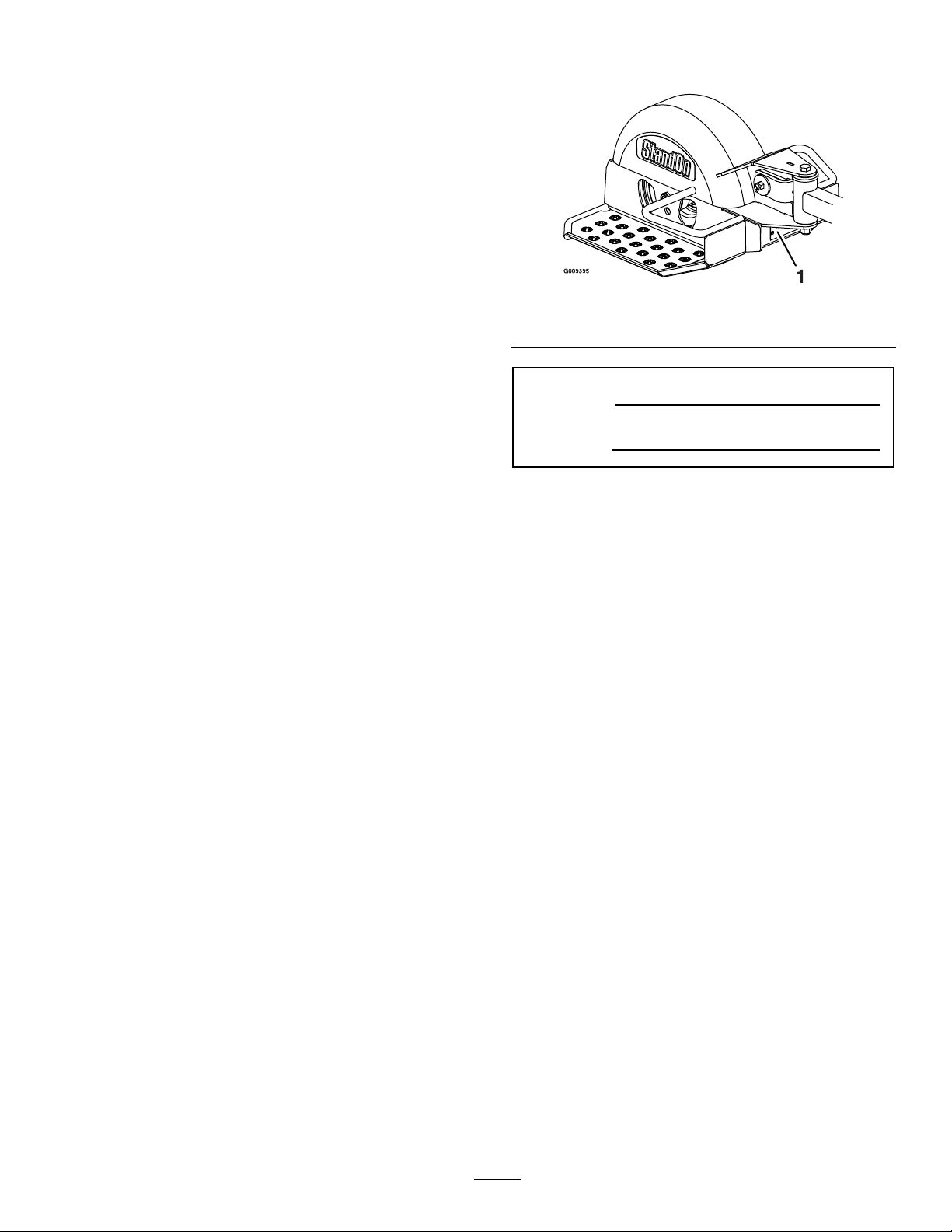
Figure1
1.Modelandserialnumberlocation
ModelNo.
SerialNo.
AllExmarkequipmentdealersanddistributorsare
keptinformedofthelatestmethodsofservicing
andareequippedtoprovidepromptandefcient
serviceintheeldorattheirservicestations.They
carryamplestockofservicepartsorcansecurethem
promptlyforyoufromthefactory.
AllExmarkpartsarethoroughlytestedandinspected
beforeleavingthefactory,however,attentionis
requiredonyourpartifyouaretoobtainthefullest
measureofsatisfactionandperformance.
Wheneveryouneedservice,genuineExmarkparts,
oradditionalinformation,contactanAuthorized
ServiceDealerorExmarkCustomerServiceandhave
themodelandserialnumbersofyourproductready .
Figure1identiesthelocationofthemodelandserial
numbersontheproduct.Writethenumbersinthe
spaceprovided.
3
Page 4

Contents
Introduction...........................................................3
Safety.....................................................................5
SafetyAlertSymbol.........................................5
SafeOperatingPractices..................................5
SafetyandInstructionalDecals.......................7
Specications.........................................................8
ModelNumbers..............................................8
Dimensions.....................................................8
Tire.................................................................8
Setup......................................................................9
AssemblyDiagram..........................................9
InstallingtheStandOnRidertoMower...........10
Operation.............................................................13
Pre-Start........................................................13
OperatingInstructions..................................13
Transporting.................................................13
Maintenance.........................................................14
RecommendedMaintenanceSchedule(s)...........14
PeriodicMaintenance.......................................14
InspectStandOn...........................................14
CheckStandOnforBuildup...........................14
LubricateGreaseFittings...............................14
LubricateCasterWheelHubs........................15
Adjustments.....................................................16
AdapterPlateandTireAdjustment................16
4
Page 5
Safety
Safety
SafetyAlertSymbol
ThisSafetyAlertSymbol(Figure2)isusedbothin
thismanualandonthemachinetoidentifyimportant
safetymessageswhichmustbefollowedtoavoid
accidents
Thissymbolmeans:ATTENTION!BECOME
ALERT!YOURSAFETYISINVOLVED!
Figure2
1.Safetyalertsymbol
Thesafetyalertsymbolappearsaboveinformation
whichalertsyoutounsafeactionsorsituations
andwillbefollowedbythewordDANGER,
WARNING,orCAUTION.
DANGER:Whitelettering/Redbackground.
Indicatesanimminentlyhazardoussituationwhich,if
notavoided,Willresultindeathorseriousinjury.
WARNING:Blacklettering/Orangebackground.
Indicatesapotentiallyhazardoussituationwhich,if
notavoided,Couldresultindeathorseriousinjury.
CAUTION:Blacklettering/Yellowbackground.
Indicatesapotentiallyhazardoussituationwhich,if
notavoided,Mayresultinminorormoderateinjury.
Thismanualusestwootherwordstohighlight
information.Importantcallsattentiontospecial
mechanicalinformationandNoteemphasizes
generalinformationworthyofspecialattention.
•Neverletchildrenoruntrainedpeopleoperate
orservicetheequipment.Localregulationsmay
restricttheageoftheoperator.
•Theowner/usercanpreventandisresponsible
foraccidentsorinjuriesoccurringtohimselfor
herself,otherpeopleorproperty.
•OnlyallowthemachineoperatorontheStandOn.
Preparation
•DoNotmodifytheStandOn.
•Evaluatetheterraintodeterminewhataccessories
andattachmentsareneededtoproperlyandsafely
performthejob.Onlyuseonmachinesapproved
byExmark.
•Wearappropriateclothingincludingsafetyglasses,
substantialfootwear,longtrousers,andhearing
protection.DoNotoperatewhenbarefootor
whenwearingopensandals.
CAUTION
ThemachinethattheStandOnattachesto
producessoundlevelsinexcessof85dBAat
theoperator’searandcancausehearingloss
throughextendedperiodsofexposure.
Wearhearingprotectionwhenoperatingthis
machine.
•Inspecttheareawheretheequipmentistobe
usedandremoveallrocks,toys,sticks,wires,
bones,andotherforeignobjectswhichcanbe
thrownbythemachineandmaycausepersonal
injurytotheoperatororbystanders.
Operation
SafeOperatingPractices
Training
•ReadthetractorandStandOnOperator’sManuals
andothertrainingmaterial.Iftheoperator(s)or
mechanic(s)cannotreadEnglishitistheowner’s
responsibilitytoexplainthismaterialtothem.
•Becomefamiliarwiththesafeoperationofthe
equipment,operatorcontrols,andsafetysigns.
•Alloperatorsandmechanicsshouldbetrained.
Theownerisresponsiblefortrainingtheusers.
•Operateonlyindaylightorgoodarticiallight,
keepingawayfromholesandhiddenhazards.
•Stopengine,waitforallmovingpartstostop,
removekeyandengageparkingbrakewhenever
youleavethemower.
SlopeOperation
UseExtremecautionwhenmowingand/orturning
onslopesaslossoftractionand/ortip-overcould
occur.Theoperatorisresponsibleforsafeoperation
onslopes.
5
Page 6

Safety
DANGER
Operatingonwetgrassorsteepslopescan
causeslidingandlossofcontrol.Lossof
controland/orlossofoperator’sfooting
couldresultinafallwithanarmorleg
gettingunderthemowerorenginedeck
whichmayresultinseriousinjury,deathor
drowning.
•Mowacrossslopes,neverupanddown.
•DoNotmowslopeswhengrassiswet.
•DoNotmowneardrop-offsornearwater.
•DoNotmowslopesgreaterthan20
degrees.
•Reducespeedanduseextremecaution
onslopes.
•Avoidsuddenturnsorrapidspeed
changes.
•Seeinsidethebackcovertodeterminethe
approximateslopeangleoftheareatobemowed.
•Removeormarkobstaclessuchasrocks,tree
limbs,etc.fromthemowingarea.Tallgrasscan
hideobstacles.
•Watchforditches,holes,rocks,dipsandrisesthat
changetheoperatingangle,asroughterraincould
overturnthemachine.
•Avoidsuddenstartswhenmowinguphillbecause
themowermaytipbackwards.
•Beawarethatoperatingonwetgrass,acrosssteep
slopesordownhillmaycausethemowertolose
traction.Lossoftractiontothedrivewheelsmay
resultinslidingandalossofbrakingandsteering.
•Alwaysavoidsuddenstartingorstoppingona
slope.Iftireslosetraction,disengagetheblades
andproceedslowlyofftheslope.
•Followthemanufacturer’srecommendationsfor
wheelweightsorcounterweightstoimprove
stability.
•AlwaysinstallandremovetheStandOnas
instructed.Failuretodosowillcauseareduction
instabilityortraction.
Waitforallmovementtostopbeforeadjusting,
cleaningorrepairing.
•Usecarewhencheckingblades.Wraptheblade(s)
orweargloves,andusecautionwhenservicing
them.Onlyreplacedamagedblades.Never
straightenorweldthem.
•Keepallguards,shieldsandallsafetydevicesin
placeandinsafeworkingcondition.
•Checkallboltsfrequentlytomaintainproper
tightness.
•Frequentlycheckforwornordeteriorating
componentsthatcouldcreateahazard.
•Allreplacementpartsmustbethesameas
orequivalenttothepartssuppliedasoriginal
equipment.
MaintenanceandStorage
•Disengagedrives,setparkingbrake,stopengine
andremovekeyordisconnectsparkplugwire.
6
Page 7

SafetyandInstructionalDecals
Safety
•Keepallsafetysignslegible.Removeallgrease,
dirtanddebrisfromsafetysignsandinstructional
labels.
•Replaceallworn,damaged,ormissingsafety
signs.
•Whenreplacementcomponentsareinstalled,be
surethatcurrentsafetysignsareafxedtothe
replacedcomponents.
•Ifanattachmentoraccessoryhasbeeninstalled,
makesurecurrentsafetysignsarevisible.
1-303517
•Newsafetysignsmaybeobtainedfrom
yourauthorizedExmarkequipmentdealeror
distributororfromExmarkMfg.Co.Inc.
•Safetysignsmaybeafxedbypeelingoffthe
backingtoexposetheadhesivesurface.Apply
onlytoaclean,drysurface.Smoothtoremove
anyairbubbles.
•Familiarizeyourselfwiththefollowingsafetysigns
andinstructionlabels.Theyarecriticaltothesafe
operationofyourExmarkcommercialmower.
1-403143
103-9141
7
Page 8

Specications
Specications
ModelNumbers
SerialNos:790,000andHigher
STANDON
Dimensions
Length
35.4inches
(89.9cm)
Width
18.5inches
(47.0cm)
HeightWeight
14.9inches
(37.9cm)
50lb(23kg)
Tire
Tread
Semi-Pneumatic
Tire
ForOperatorsover250lbitisrecommendedtouse
pneumatictireassemblyP/N103-3798.
Smooth
Size
11x4.00–5
8
Page 9

Setup
AssemblyDiagram
Item
18
22
3
4
5
6
7
81
9
10
11*2
Setup
QuantityDescription
Nut,Nyloc3/8-16Flg
Plate,Back-Up
2
Plate,Adapter
8
Screw,HH3/8-16x11/4
1
Asm,FramePullW/Decals
1
Asm,PullArmW/Brgs
1
Guard,Top
Screw,HH3/8–16x43/4
1
Nut,HexFlg-SideLock3/8-16
1
Asm,SulkyFrameW/Decals
Decals,Replacement(TurfTracerand
VikingHydroOnly)
121
*Notshowninillustration
Washer,SpringDisc
Figure3
9
Page 10

Setup
3
4
4
2
1
1
2
G009397
InstallingtheStandOnRider
toMower
MountingthePullFrame
1.Locatethepullframeandtwoadapterplates.
Installthepullframetotheadapterplatesusing
four3/8-16x11/4inchhexcapscrewsandfour
3/8-16inchnylocnutsasshowninFigure4.
Figure4
1.3/8-16inchnylocnuts
2.Adapterplate
3.Pullframe
4.3/8-16x11/4inchhexcapscrews
Figure5
1.Removethesetwodecals.
c.Centertheadapterplatesonthelowerrear
surfaceofthemowerenginedeckand
markthefourholelocationsshownin
Figure6.Drillfour0.407inchdiameter
holesthroughtheenginedeckatthe
markedlocations.
2.Mountingthepullframeassemblytotheengine
deck:
A.ForTurfTracerandVikingHydroUnits
Only:
a.Ifyourunithasfourholesdrilledinthe
rearsurfaceoftheenginedeckproceedto
stepc;ifnot,continuewithstepb.
b.Removethetwodecalsonthelowerrear
surfaceoftheenginedeck(seeFigure5).
1.Pullframeandadapterplateassembly
2.Markanddrilltwoholeseachside.
Figure6
d.Applythetworeplacementdecalstothe
enginedeckbetweenthemountingholes
(seeFigure7).
10
Page 11

Figure7
1.Replacementdecals
e.Alignthepullframeandadapterplate
assemblytotherearsurfaceoftheengine
deck.Measurethedistancefromthe
bottomofthepullframetotheground.
Choosethemountholesthatwillattaina
distanceapproximately8inches(20cm).
Installthemountbracketstothemower
enginedeckusingtwo3/8-16x11/4inch
hexcapscrews,twoback-upplates,and
two3/8-16inchnylocnutsasshownin
Figure8).
Setup
Choosethemountholesthatwillattaina
distanceofapproximately8inches.
b.Installtheadapterplatestothemower
enginedeckusingtwo3/8-16x1/4
inchhexcapscrewsandtwo3/8-16inch
angednylocnutsasshowninFigure9.
Figure9
1.3/8-16x1/4inchhexcapscrews
2.Pullframeandadapterplateassembly
3.3/8-16inchangednylocnuts
Figure8
1.3/8-16x11/4inchhex
capscrews
2.Pullframeandadapter
plateassembly
3.3/8-16inchnylocnuts
B.ForTurfTracerHPandMetroHPUnits:
a.Alignthepullframeandadapterplate
assemblytotherearsurfaceoftheengine
deck.Measurethedistancefromthe
bottomofthepullframetotheground.
MountingthePullArmandPlatform
ForTurfTracer,TurfTracerHP,MetroHP,and
VikingHydroUnits:
1.Locatethepullarmassembly.Alignthepull
armassemblywiththepullframeasshownin
Figure10.Squeezethequickconnectpinson
thepullarmassemblyandattachthepullarm
assemblytothepullframe.
11
Page 12

Setup
Figure10
1.Pullarmassembly
2.Quickconnectpins
2.Removethe3/8-16x43/4inchhexcapscrew .
springdiscwasher,and3/8-16inchhexange
sidelocknutfromthepivothub.
3.Pullframe
Important:Foroptimalperformance,the
StandOnpullarmtopsurfaceshouldbe
horizontaltothegroundsurface.
Toobtainapositionasclosetohorizontalas
possible,theadjustmentbracketsandtheplatform
wheelcanberepositioned(seeAdapterPlate
andTireAdjustmentsectioninMaintenance).
3.Locatethesulkyframeassemblyandalignwith
thepullarmassembly.Re-installthe3/8-16x4
3/4inchhexcapscrew ,springdiscwasher,and
3/8-16inchhexangesidelocknutremovedin
step1asshowninFigure11.T orqueto35-38
ft-lb(47-52N-m).
Figure11
1.Pullframeassembly4.Sulkyframeassembly
2.3/8-16x43/4inchhex
capscrew
3.Springdiscwasher
5.3/8-16inchhexange
sidelocknut
12
Page 13

Operation
Operation
Note:Determinetheleftandrightsidesofthe
machinefromthenormaloperatingposition.
Pre-Start
1.Makesureyouunderstandthecontrols,their
locations,theirfunctions,andtheirsafety
requirements.
2.Practiceoperatingthemachinewithoutthe
StandOnuntilfamiliarwiththecontrols.
3.PracticeoperatingthemachinewiththeStandOn
attachedonlarge,open,levelterrainwithno
obstaclespresentbeforeuse.theStandOnwill
affectthemachineoperation,especiallyonslopes,
whenturning,andwhenstopping.
4.Ensurethepullarmassemblyissecurely
connectedtothepullframe.
5.ForMetroHPUnits:Wheeldrivebelttension
mayneedadjustment.Refertothemachine
Operator’sManualforadjustmentinstructions.
6.ForoperationofStandOnwithMetroHP ,Viking
Hydro,andTurfTracerHPonhillyterrain,
frontweightkitaccessory,P/N103-2637,is
recommended.
1.UsecarewhenturningtoensurethatyouDoNot
swingyourselfandthesulkyintoobstacles.
2.Whenturning,leanforwardandtowardthe
directionoftheturntohelpinkeepingbalance.
Transporting
TransportingaUnit
PlacetheStandOninthetransportpositionwhen
loadingaunitonatrailer,unloadingaunitfroma
trailer,oroperatinginreverse(seeFigure12).
Figure12
1.Latchpin
2.Rotateplatformintotransportpositionandlockwith
latchpin
7.Foroperatorsover250lb,itisrecommendedto
usepneumatictireassembly,P/N103-3798.
OperatingInstructions
Mowing
DANGER
IftheStandOnrotatesbeyond90°,thereis
apotentialcrushinghazard.Rapidrotation
beyond90°cancausetheStandOnto
jackknifeintothemowerenginedeckand
causeseriousinjury.
•DismounttheStandOnandplacein
transportpositionbeforeoperatingin
reverse.
•Reducespeedwhenmakingsharpturns
andoperatingonslopes.
13
Page 14

Maintenance
Maintenance
Note:Determinetheleftandrightsidesofthemachinefromthenormaloperatingposition.
WARNING
Whilemaintenanceoradjustmentsarebeing
made,someonecouldstarttheengine.
Accidentalstartingoftheenginecould
seriouslyinjureyouorotherbystanders.
Removethekeyfromtheignitionswitch,
engageparkingbrake,andpullthewire(s)
offthesparkplug(s)beforeyoudoany
maintenancetotheunitorStandOn.
Alsopushthewire(s)asidesoitdoesnot
accidentallycontactthesparkplug(s).
RecommendedMaintenanceSchedule(s)
MaintenanceService
Interval
Beforeeachuseordaily
Every25hours
Yearly
MaintenanceProcedure
•InspecttheStandOn.
•Checkfordirt/mudbuildupbetweentireandfender.
•Greasepullarmpivot.
•Greasecasterwheelhub.
•Lubricatethecasterwheelhubs.
PeriodicMaintenance
InspectStandOn
ServiceInterval:Beforeeachuseordaily
1.Stopengine,waitforallmovingpartstostop,and
removekey.Engageparkingbrake.
2.Inspectforloosehardware.Tightenanyloose
hardware.
LubricateGreaseFittings
Note:Seechartforserviceintervals.
1.Stopengine,waitforallmovingpartstostop,and
removekey.Engageparkingbrake.
2.LubricatettingswithNGLIgrade#2
multi-purposegungrease.
Refertothefollowingchartforttinglocations
andlubricationschedule.
3.Inspectforwearordamagedaily.Replaceor
repairwornpartsasneededbeforeoperating.
CheckStandOnforBuildup
ServiceInterval:Beforeeachuseordaily
Checkfordirt/mudbuildupbetweentireandfender.
Removebuildupbeforeoperating.
14
Fitting
Locations
1.PullArm
Pivot
2.Caster
WheelHub
LubricationChart
Initial
Pumps
1–21
0*
Numberof
Places
Service
Interval
Yearly
1
Yearly
Page 15

Maintenance
LubricateCasterWheelHubs
ServiceInterval:Yearly
1.Stopengine,waitforallmovingpartstostop,and
removekey.Engageparkingbrake.
Figure13
1.Sealguard2.Spacernutwithwrench
ats
2.Removethecasterwheelfromthesulkyframe.
3.Removesealguardsfromthewheelhub.
4.Removeoneofthespacernutsfromtheaxle
assemblyinthecasterwheel.Notethatthread
lockingadhesivehasbeenappliedtolockthe
spacernutstotheaxle.Removetheaxle(with
theotherspacernutstillassembledtoit)from
thewheelassembly.
5.Pryoutseals,andinspectbearingsforwearor
damageandreplaceifnecessary.
6.PackthebearingswithaNGLIgrade#1
multi-purposegrease.
7.Insertonebearing,onenewsealintothewheel.
11.Insertthesecondbearingandnewsealintothe
wheel.
12.Applyathreadlockingadhesivetothesecond
spacernutandthreadontotheaxlewiththe
wrenchatsfacingoutward.
13.Torquethenutto75-80in-lb(8-9N-m),loosen,
thenre-torqueto20-25in-lb(2-3N-m).Make
sureaxledoesnotextendbeyondeithernut.
14.Reinstallthesealguardsoverthewheelhuband
insertwheelintothesulkyframe.Reinstallcaster
boltandtightennutfully .
Important:Topreventsealandbearingdamage,
checkthebearingadjustmentoften.Spinthe
castertire.Thetireshouldnotspinfreely
(morethan1or2revolutions)orhaveanyside
play.Ifthewheelspinsfreely,adjusttorqueon
spacernutuntilthereisaslightamountofdrag.
Reapplythreadlockingadhesive.
Note:Seals(ExmarkPN103-0063)mustbe
replaced.
8.Iftheaxleassemblyhashadbothspacernuts
removed(orbrokenloose),applyathreadlocking
adhesivetoonespacernutandthreadontothe
axlewiththewrenchatsfacingoutward.Do
Notthreadspacernutallofthewayontotheend
oftheaxle.Leaveapproximately1/8inch(3mm)
fromtheoutersurfaceofthespacernuttothe
endoftheaxleinsidethenut.
9.Inserttheassemblednutandaxleintothewheel
onthesideofthewheelwiththenewsealand
bearing.
10.Withtheopenendofthewheelfacingup,ll
theareainsidethewheelaroundtheaxlefullof
NGLIgrade#1multi-purposegrease.
15
Page 16

Maintenance
Adjustments
AdapterPlateandTire
Adjustment
Important:Foroptimalperformance,the
StandOnpullarmtopsurfaceshouldbe
horizontaltothegroundsurface.
Toobtainahorizontalpullarm,theadapterplates
andtheplatformwheelcanberepositioned(see
Figure14).
Figure14
1.Adapterplatescanbemovedtoadjustheightposition
2.Pullarmshouldbehorizontaltoground
3.Wheelcanbemountedineitherholeforheight
adjustment
Note:Toachievemoregroundclearanceforhigher
cuttingheights,raisetheplatformbyusingthelower
wheeladjustmentholeandcorrespondingadapter
plateholes.
16
Page 17

Conditions and Products Covered
Exmark Mfg. Co. Inc. and its affiliate, Exmark Warranty
Company, pursuant to an agreement between them, jointly
warrant on the terms and conditions herein, that we will repair,
replace or adjust any part on these products and found by us
(in the exercise of our reasonable discretion) to be defective in
factory materials or workmanship for a period of one year.
This warranty applies to Exmark commercial attachments and
accessories sold in the U.S. or Canada. This warranty may
only be assigned or transferred to a second (or third) owner by
an authorized Exmark dealer. The warranty period commences
upon the date of the original retail purchase.
Warranty Exceptions Warranty Period
• Bags, Belts and Tires 90 days
This warranty only includes the cost of parts and labor.
Items and Conditions Not Covered
This warranty does not cover the following:
• Pickup and delivery charges to and from any authorized
Exmark Service Dealer.
• Any damage or deterioration due to normal use, wear and
tear, or exposure.
• Cost of regular maintenance service or parts, such as filters,
fuel, lubricants, tune-up parts, and adjustments.
• Any product or part which has been altered or misused or
required replacement or repair due to normal wear,
accidents, or lack of proper maintenance.
• Any repairs necessary due to use of parts, accessories or
supplies, including gasoline, oil or lubricants, incompatible
with the attachment or accessory or other than as
recommended in the operator's manual or other operational
instructions provided by Exmark.
All warranty work must be performed by an authorized
Exmark Service Dealer using Exmark approved replacement
parts.
Instructions for Obtaining Warranty Service
The product must be registered with original proof of purchase
by an Exmark Service Dealer before obtaining any warranty
service.
Contact any Exmark Service Dealer to arrange service at their
dealership. To locate a dealer convenient to you, access our
website at www.exmark.com. U.S. or Canada customers may
also call 402-223-6375.
If for any reason you are dissatisfied with the Service Dealer’s
analysis or with the assistance provided, contact us at:
Exmark Customer Service Department
The Exmark Warranty Company
2101 Ashland Avenue
Beatrice, NE 68310
402-223-6375 or
service@exmark.com
Owner’s Responsibilities
The Exmark attachment or accessory, including any defective
part, must be returned to an authorized Exmark service dealer
within the warranty period. This warranty extends only to
commercial attachments and accessories operated under
normal conditions. You must read the operator’s manual. You
must also properly service and maintain your Exmark product
as described in the operator’s manual or other operational
instructions provided by Exmark. Such routine maintenance,
whether performed by a dealer or by you, is at your expense.
General Conditions
The sole liability of Exmark and Exmark Warranty Company
with respect to this warranty shall be repair or replacement of
defective components as set forth herein. Neither Exmark
nor Exmark Warranty Company shall be liable for any
incidental or consequential loss or damage.
Such damages include but are not limited to:
• Expenses related to gasoline, oil or lubricants.
• Travel time, overtime, after hours time or other
extraordinary repair charges or charges relating to repairs or
replacements outside of normal business hours at the place
of business of the authorized Exmark Service Dealer.
• Rental of like or similar replacement equipment during the
period of any warranty, repair or replacement work.
• Any telephone or telegram charges or travel charges.
• Loss or damage to person or property other than that
covered by the terms of this warranty.
• Any claims for lost revenue, lost profit or additional cost as
a result of a claim of breach of warranty.
• Attorney's fees.
No Claim of breach of warranty shall be cause for cancellation
or rescission of the contract of sale of any Exmark attachment
or accessory.
All implied warranties of merchantability (that the
product is fit for ordinary use) and fitness for use (that the
product is fit for a particular purpose) are limited to the
duration of the express warranty.
Some states do not allow exclusions of incidental or
consequential damages, or limitations on how long an
implied warranty lasts, so the above exclusions and
limitations may not apply to you.
This warranty gives you specific legal rights, and you may
also have other rights which vary from state to state.
Exmark Commercial
Attachments and Accessories
1 Year Limited Warranty
G4500-433
17
Page 18

ServiceRecord
Date:
DescriptionofWorkDone:ServiceDoneBy:
18
Page 19

19
Page 20

MI D-MOUNT RIDING ACCE SSORIES AND OPTIONS
SEE EXMARK’S COMPLETE LINE OF ACCESSORIES AND OPTIONS
WALK-BEHIND ACCESSORIES AND OPTIONS
GRASS CATCHER
MICRO-MULCH SYSTEM
TURF STRIPER
STANDON
CUSTOM RIDE SEAT SUSPENSION SYSTEM
FULL SUSPENSION SEAT
DECK LIFT ASSIST KIT
HITCH KIT
LIGHT KIT
12
V POWER PORT
MICRO-MULCH SYSTEM
OPERATOR CONTROLLED DISCHARGE
ROLL OVER PROTECTION SYSTEM (ROPS)
SUN SHADE
TRASH CONTAINER
TURF STRIPER
ULTRA VAC COLLECTION SYSTEM
ULTRA VAC QUICK DISPOSAL SYSTEM
OU T-FRO NT RIDING ACCESSORI ES AND OPTI ONS
CUSTOM RIDE SEAT SUSPENSION SYSTEM
DUAL-TAIL WHEEL
FLOOR PAN EXTENDER
HITCH KIT
LIGHT KIT
MICRO-MULCH SYSTEM
ROLL OVER PROTECTION SYSTEM (ROPS)
SNOW BLADE
SNOWBLOWER
SUN SHADE
TRASH CONTAINER
ULTRA VAC COLLECTION SYSTEM
ULTRA VAC QUICK DISPOSAL SYSTEM
WEATHER CAB
PlaceModelNo.andSerialNo.
LabelHere(IncludedintheLiterature
Pack)orFillinBelow
ModelNo.
SerialNo.
©2008ExmarkMfg.Co.,Inc.
IndustrialParkBox808
Beatrice,NE68310
AllRightsReserved
DatePurchased
PartNo.4500-435Rev.A
(402)223-6300
Fax(402)223-5489
PrintedintheUSA
www.exmark.com
 Loading...