

Page 1
RADIUS®
ForSerialNos.
400,000,000&Higher
PartNo.4502-907Rev.B
Page 2

WARNING
CALIFORNIA
Proposition65Warning
Thisproductcontainsachemical
orchemicalsknowntotheStateof
Californiatocausecancer,birthdefects,
orreproductiveharm.
Theengineexhaustfromthisproduct
containschemicalsknowntotheStateof
Californiatocausecancer,birthdefects,
orotherreproductiveharm.
Important:ItisaviolationofCaliforniaPublic
ResourceCodeSection4442or4443touse
oroperatetheengineonanyforest-covered,
brush-covered,orgrass-coveredlandunlessthe
engineisequippedwithasparkarrester,as
denedinSection4442,maintainedineffective
workingorderortheengineisconstructed,
equipped,andmaintainedforthepreventionof
re.
Toacquireasparkarresterforyourunit,seeyour
EngineServiceDealer.
Thissparkignitionsystemcomplieswiththe
CanadianstandardICES-002.Cesystèmed’allumage
parètincelledevèhiculeestconformeàlanorme
NMB-002duCanada.
ForallmodelsthatdonothaveExmarkengines,
pleaserefertotheenginemanufacturer’s
informationincludedwiththemachine.
Labeledpowerratingsaresuppliedbytheengine
manufacturerinaccordancewithSAEtesting
andgross/netpowerratingstandards(J1940,
J1995,J1349).
Exmarkreservestherighttomakechangesor
addimprovementstoitsproductsatanytime
withoutincurringanyobligationtomakesuch
changestoproductsmanufacturedpreviously.
Exmark,oritsdistributorsanddealers,accept
noresponsibilityforvariationswhichmaybe
evidentintheactualspecicationsofitsproducts
andthestatementsanddescriptionscontained
inthispublication.
©2016ExmarkMfg.Co.,Inc.
IndustrialParkBox808
Beatrice,NE68310
2
Contactusatwww.Exmark.com.
PrintedintheUSA
AllRightsReserved
Page 3
Introduction
CONGRATULATIONSonthepurchaseofyour
ExmarkMower.Thisproducthasbeencarefully
designedandmanufacturedtogiveyouamaximum
amountofdependabilityandyearsoftrouble-free
operation.
Thismanualcontainsoperating,maintenance,
adjustment,andsafetyinstructionsforyourExmark
mower.
BEFOREOPERATINGYOURMOWER,
CAREFULLYREADTHISMANUALINITS
ENTIRETY.
Byfollowingtheoperating,maintenance,andsafety
instructions,youwillprolongthelifeofyourmower,
maintainitsmaximumefciency,andpromotesafe
operation.
Important:Tomaximizesafety,performance,
andproperoperationofthismachine,itis
essentialthatalloperatorscarefullyreadand
fullyunderstandthecontentsoftheOperator’s
manualprovidedwiththeproduct.Safe
operationofExmarkequipmentisessential.
Failuretocomplywiththeoperatinginstructions
orreceivepropertrainingmayresultininjury.
Gotohttp://www.Exmark.comforadditional
safeoperationinformation,suchassafetytips,
trainingmaterials,andOperator’smanuals.
Ifadditionalinformationisneeded,orshould
yourequiretrainedmechanicservice,contactyour
authorizedExmarkequipmentdealerordistributor.
AllExmarkequipmentdealersanddistributorsare
keptinformedofthelatestmethodsofservicing
andareequippedtoprovidepromptandefcient
serviceintheeldorattheirservicestations.They
carryamplestockofservicepartsorcansecurethem
promptlyforyoufromthefactory.
AllExmarkpartsarethoroughlytestedandinspected
beforeleavingthefactory,however,attentionis
requiredonyourpartifyouaretoobtainthefullest
measureofsatisfactionandperformance.
Wheneveryouneedservice,genuineExmarkparts,
oradditionalinformation,contactanAuthorized
ServiceDealerorExmarkCustomerServiceandhave
themodelandserialnumbersofyourproductready.
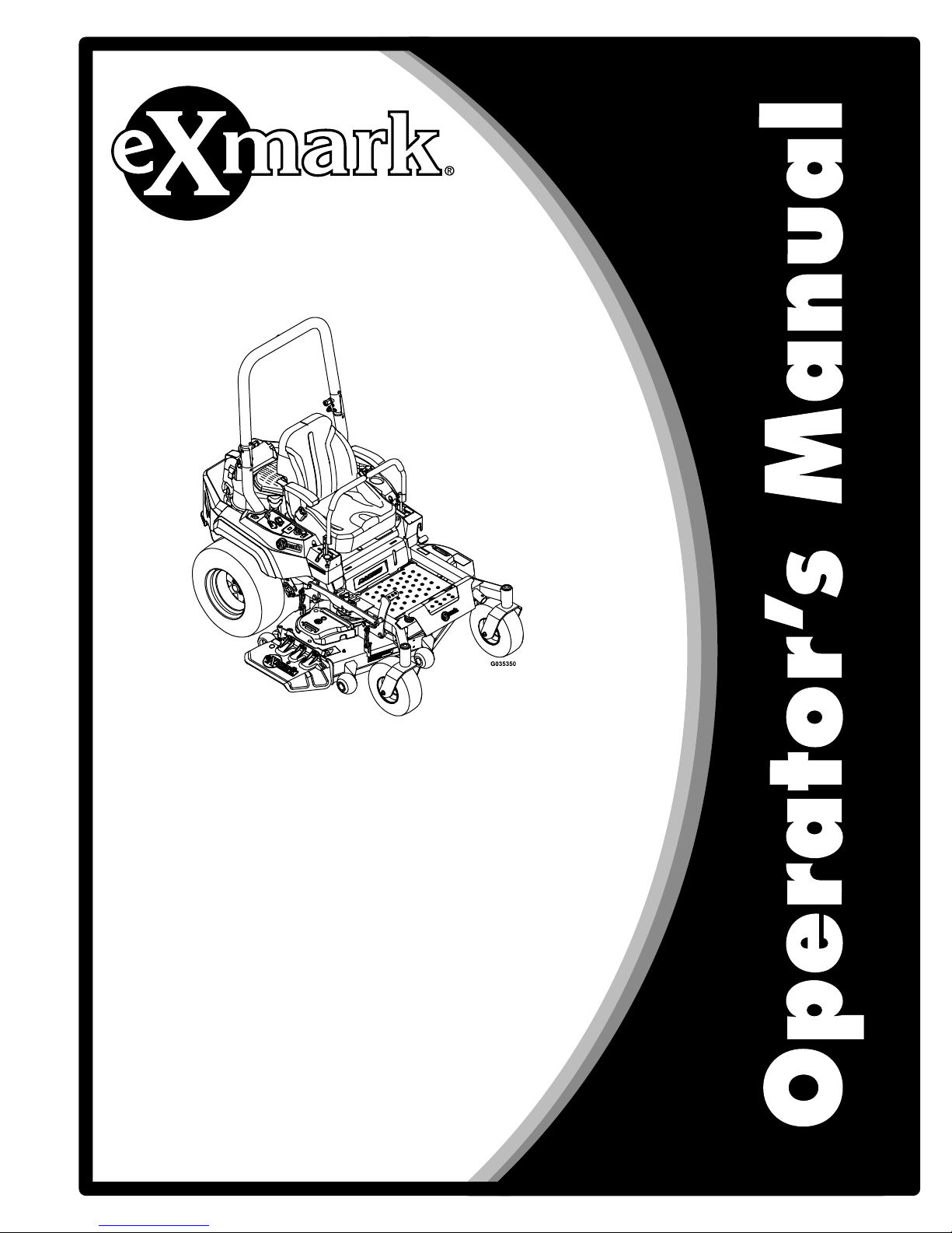
Figure1identiesthelocationofthemodelandserial
numbersontheproduct.Writethenumbersinthe
spaceprovided.
Figure1
1.Modelandserialnumberlocation
ModelNo.
SerialNo.
3
Page 4

Contents
Introduction...........................................................3
Safety.....................................................................5
SafetyAlertSymbol.........................................5
SafeOperatingPractices..................................5
SafetyandInstructionalDecals......................11
Specications........................................................18
Systems..........................................................18
Dimensions....................................................21
TorqueRequirements.....................................23
ProductOverview.................................................23
Operation..............................................................24
Controls.........................................................24
Pre-Start.........................................................26
OperatingInstructions...................................27
Transporting..................................................32
Maintenance..........................................................35
RecommendedMaintenanceSchedule(s)............35
PeriodicMaintenance........................................36
EngineMaintenance.......................................36
ServicingtheEngineOil.................................40
ServicingtheSparkPlug-Exmark708cc
Engine.......................................................48
ServicingtheSparkPlug-Kohler
Engine.......................................................50
ServicingtheSparkPlug-Kawasaki
Engine.......................................................51
CheckBatteryCharge.....................................52
CheckMowerBlades......................................53
CheckSafetyInterlockSystem........................55
CheckRolloverProtectionsSystems(Roll
Bar)Knobs.................................................58
CheckSeatBelt...............................................58
CheckforLooseHardware.............................58
CheckHydraulicOilLevel..............................58
CheckTirePressures......................................58
CheckConditionOfBelts...............................58
LubricateGreaseFittings................................59
ReplaceEmissionsAirIntakeFilter(If
Applicable).................................................60
ChangeHydraulicSystemFilterand
Fluid..........................................................61
CheckSparkArrester(ifequipped)..................62
ThreadLockingAdhesives..............................62
Copper-BasedAnti-seize...............................62
DielectricGrease............................................62
Adjustments......................................................63
DeckLeveling................................................63
AdjustingtheBladeSlope...............................64
PumpDriveBeltTension................................65
DeckBeltTension..........................................65
AdjustingtheParkingBrake............................65
MotionControlHandleAdjustment...............66
FullForwardTrackingAdjustment..................66
MotionControlLinkageAdjustment..............67
AdjustingtheSeatRideSuspensionS-Series
Only...........................................................68
ElectricClutchAdjustment.............................68
Cleaning............................................................69
CleanEngineandExhaustSystem
Area...........................................................69
RemoveEngineShroudsandClean
CoolingFins...............................................69
CleanDebrisFromMachine...........................69
CleanGrassBuild-UpUnderDeck.................69
WasteDisposal...............................................69
Troubleshooting....................................................71
Schematics............................................................73
4
Page 5

Safety
Safety
SafetyAlertSymbol
ThislawnmowermeetsorexceedstheB71.4
specicationsoftheAmericanNationalStandards
Instituteineffectatthetimeofproduction.
Exmarkdesignedandtestedthislawnmowertooffer
reasonablysafeservice;however,failuretocomply
withthefollowinginstructionsmayresultinpersonal
injury.
ThisSafetyAlertSymbol(Figure2)isusedbothin
thismanualandonthemachinetoidentifyimportant
safetymessageswhichmustbefollowedtoavoid
accidents.
Thissymbolmeans:ATTENTION!BECOME
ALERT!YOURSAFETYISINVOLVED!
Figure2
SafetyAlertSymbol
Thesafetyalertsymbolappearsaboveinformation
whichalertsyoutounsafeactionsorsituations
andwillbefollowedbythewordDANGER,
WARNING,orCAUTION.
DANGER:Indicatesanimminentlyhazardous
situationwhich,ifnotavoided,Willresultindeathor
seriousinjury.
WARNING:Indicatesapotentiallyhazardous
situationwhich,ifnotavoided,Couldresultindeath
orseriousinjury.
CAUTION:Indicatesapotentiallyhazardous
situationwhich,ifnotavoided,Mayresultinminor
ormoderateinjury.
Thismanualusestwootherwordstohighlight
information.Importantcallsattentiontospecial
mechanicalinformationandNoteemphasizes
generalinformationworthyofspecialattention.
SafeOperatingPractices
Training
•ReadtheOperator’sManualandothertraining
material.Iftheoperator(s)ormechanic(s)cannot
readthismanual,itistheowner’sresponsibilityto
explainthismaterialtothem;otherlanguagesmay
beavailableonourwebsite.
•Becomefamiliarwiththesafeoperationofthe
equipment,operatorcontrols,andsafetysigns.
•Alloperatorsandmechanicsshouldbetrained.
Theownerisresponsiblefortrainingtheusers.
•Neverletchildrenoruntrainedpeopleoperate
orservicetheequipment.Localregulationsmay
restricttheageoftheoperator.
•Onlyadultsandmatureteenagersshouldoperate
amower,andevenmatureteenagersshouldhave
adultsupervision.Besureateenager:
1.hasreadandunderstandstheOperator's
Manualandrecognizestherisksinvolved;
2.issufcientlymaturetousecaution;and
3.isofsufcientsizeandweighttooperate
thecontrolscomfortablyandtomanagethe
mowerwithouttakingrisks.
•Theowner/usercanpreventandisresponsible
foraccidentsorinjuriesoccurringtohimselfor
herself,otherpeopleorproperty.
Preparation
•Evaluatetheterraintodeterminewhataccessories
andattachmentsareneededtoproperlyand
safelyperformthejob.Onlyuseaccessoriesand
attachmentsapprovedbyExmark.
•Wearappropriateclothingincludingsafetyglasses,
substantialslip-resistantfootwear,andhearing
protection.Longhair,looseclothingorjewelry
maygettangledinmovingparts.
CAUTION
Thismachineproducessoundlevelsinexcess
of85dBAattheoperator’searandcancause
hearinglossthroughextendedperiodsof
exposure.
Wearhearingprotectionwhenoperatingthis
machine.
•Inspecttheareawheretheequipmentistobe
usedandremoveallrocks,toys,sticks,wires,
5
Page 6

Safety
bones,andotherforeignobjectswhichcanbe
thrownbythemachineandmaycausepersonal
injurytotheoperatororbystanders.
DANGER
Incertainconditionsgasolineisextremely
ammableandvaporsareexplosive.
Areorexplosionfromgasolinecanburn
you,others,andcausepropertydamage.
•Fillthefueltankoutdoorsonlevelground,
inanopenarea,whentheengineiscold.
Wipeupanygasolinethatspills.
•Neverrellthefueltankordrainthe
machineindoorsorinsideanenclosed
trailer.
•DoNotllthefueltankcompletelyfull.
Fillthefueltanktothebottomoftheller
neck.Theemptyspaceinthetankallows
gasolinetoexpand.Overllingmayresult
infuelleakageordamagetotheengine
oremissionsystem.
•Neversmokewhenhandlinggasoline,and
stayawayfromanopenameorwhere
gasolinefumesmaybeignitedbyspark.
•Storegasolineinanapprovedcontainer
andkeepitoutofthereachofchildren.
•Addfuelbeforestartingtheengine.Never
removethecapofthefueltankoradd
fuelwhenengineisrunningorwhenthe
engineishot.
•Iffuelisspilled,DoNotattempttostart
theengine.Moveawayfromtheareaof
thespillandavoidcreatinganysourceof
ignitionuntilfuelvaporshavedissipated.
•DoNotoperatewithoutentireexhaust
systeminplaceandinproperworking
condition.
DANGER
Incertainconditionsduringfueling,static
electricitycanbereleasedcausingaspark
whichcanignitegasolinevapors.Areor
explosionfromgasolinecanburnyouand
othersandcausepropertydamage.
•Alwaysplacegasolinecontainersonthe
groundawayfromyourvehiclebefore
lling.
•DoNotllgasolinecontainersinsidea
vehicleoronatruckortrailerbedbecause
interiorcarpetsorplastictruckbedliners
mayinsulatethecontainerandslowthe
lossofanystaticcharge.
•Whenpractical,removegas-powered
equipmentfromthetruckortrailerand
refueltheequipmentwithitswheelson
theground.
•Ifthisisnotpossible,thenrefuelsuch
equipmentonatruckortrailerfroma
portablecontainer,ratherthanfroma
gasolinedispensernozzle.
•Ifagasolinedispensernozzlemustbe
used,keepthenozzleincontactwiththe
rimofthefueltankorcontaineropening
atalltimesuntilfuelingiscomplete.Do
Notuseanozzlelockopendevice.
WARNING
Gasolineisharmfulorfatalifswallowed.
Long-termexposuretovaporshascaused
cancerinlaboratoryanimals.Failuretouse
cautionmaycauseseriousinjuryorillness.
•Avoidprolongedbreathingofvapors.
•Keepfaceawayfromnozzleandgas
tank/containeropening.
•Keepawayfromeyesandskin.
•Neversiphonbymouth.
•Checkthattheoperatorpresencecontrols,
safetyswitches,andshieldsareattachedand
functioningproperly.DoNotoperateunlessthey
arefunctioningproperly.
6
Page 7

Safety
Operation
WARNING
Operatingengineparts,especiallythemufer,
becomeextremelyhot.Severeburnscanoccur
oncontactanddebris,suchasleaves,grass,
brush,etc.cancatchre.
•Allowengineparts,especiallythemufer,to
coolbeforetouching.
•Removeaccumulateddebrisfrommuferand
enginearea.
WARNING
Engineexhaustcontainscarbonmonoxide,
whichisanodorlessdeadlypoisonthatcankill
you.
DoNotrunengineindoorsorinasmallconned
areawheredangerouscarbonmonoxidefumes
cancollect.
•Operateonlyindaylightorgoodarticiallight,
keepingawayfromholesandhiddenhazards.
•Lightningcancausesevereinjuryordeath.If
lightningisseenorthunderisheardinthearea,
DoNotoperatethemachine;seekshelter.
•Besurealldrivesareinneutralandparkingbrake
isengagedbeforestartingengine.Useseatbelts
withtherollbarintheraisedandlockedposition.
•Neveroperatethemowerwithdamagedguards,
shields,orcovers.Alwayshavesafetyshields,
guards,switchesandotherdevicesinplaceandin
properworkingcondition.
•Nevermowwiththedischargedeectorraised,
removedoralteredunlessthereisagrass
collectionsystemormulchkitinplaceand
workingproperly .
•DoNotchangetheenginegovernorsettingor
overspeedtheengine.
•Parkmachineonlevelground.Stopengine,wait
forallmovingpartstostop,removekeyand
engageparkingbrake:
–Beforechecking,cleaningorworkingonthe
mower.
–Afterstrikingaforeignobjectorabnormal
vibrationoccurs(inspectthemowerfor
damageandmakerepairsbeforerestarting
andoperatingthemower).
–Beforeclearingblockages.
–Wheneveryouleavethemower.
•Stopengine,waitforallmovingpartstostop,and
engageparkingbrake:
–Beforerefueling.
–Beforedumpingthegrasscatcher.
WARNING
Hands,feet,hair,clothing,oraccessoriescan
becomeentangledinrotatingparts.Contact
withtherotatingpartscancausetraumatic
amputationorseverelacerations.
•DoNotoperatethemachinewithout
guards,shields,andsafetydevicesinplace
andworkingproperly.
•Keephands,feet,hair,jewelry,orclothing
awayfromrotatingparts.
•NEVERcarrypassengers.DONOToperate
themowerwhenpeople,especiallychildren,or
petsareinthearea.
•Bealert,slowdownandusecautionwhen
makingturns.Lookbehindandtothesidebefore
changingdirections.
•Stoptheblades,slowdown,andusecaution
whencrossingsurfacesotherthangrassandwhen
transportingthemowertoandfromtheareato
bemowed.
•Beawareofthemowerdischargepathanddirect
dischargeawayfromothers.
•DoNotoperatethemowerundertheinuence
ofalcoholordrugs.
•Useextremecarewhenloadingorunloadingthe
machineintoatrailerortruck.
•Usecarewhenapproachingblindcorners,shrubs,
trees,orotherobjectsthatmayobscurevision.
SlopeOperation
UseExtremecautionwhenmowingand/orturning
onslopesaslossoftractionand/ortip-overcould
occur.Theoperatorisresponsibleforsafeoperation
onslopes.
7
Page 8

Safety
DANGER
Operatingonwetgrassorsteepslopescancause
slidingandlossofcontrol.Wheelsdroppingover
edges,ditches,steepbanks,orwatercancause
rollovers,whichmayresultinseriousinjury,
deathordrowning.
•DoNotmowslopeswhengrassiswet.
•DoNotmowneardrop-offsornearwater.
•DoNotmowslopesgreaterthan15degrees.
•Reducespeedanduseextremecautionon
slopes.
•Avoidsuddenturnsorrapidspeedchanges.
•Keeptherollbarintheraisedandlocked
positionanduseseatbelt.
•Seeinsidethebackcovertodeterminethe
approximateslopeangleoftheareatobemowed.
•Useawalkbehindmowerand/orahandtrimmer
neardrop-offs,ditches,steepbanksorwater.
(Figure3).
Figure3
1.SafeZone-Usethemowerhereonslopeslessthan15
degrees
2.DangerZone-Useawalkbehindmowerand/orhand
trimmeronslopesgreaterthan15degrees,near
drop-offsandwater.
3.Water
•Removeormarkobstaclessuchasrocks,tree
limbs,etc.fromthemowingarea.Tallgrasscan
hideobstacles.
•Watchforditches,holes,rocks,dipsandrisesthat
changetheoperatingangle,asroughterraincould
overturnthemachine.
•Avoidsuddenstartswhenmowinguphillbecause
themowermaytipbackwards.
•Beawarethatoperatingonwetgrass,acrosssteep
slopesordownhillmaycausethemowertolose
traction.Lossoftractiontothedrivewheelsmay
resultinslidingandalossofbrakingandsteering.
•Alwaysavoidsuddenstartingorstoppingona
slope.Iftireslosetraction,disengagetheblades
andproceedslowlyofftheslope.
•Followthemanufacturer’srecommendationsfor
wheelweightsorcounterweightstoimprove
stability.
•Useextremecarewithgrasscatchersor
attachments.Thesecanchangethestabilityofthe
machineandcauselossofcontrol.
UsingtheRolloverProtectionSystem
(ROPS)
ARolloverProtectionSystem(rollbar)isinstalled
ontheunit.
WARNING
Thereisnorolloverprotectionwhentherollbar
isdown.Wheelsdroppingoveredges,ditches,
steepbanks,orwatercancauserollovers,which
mayresultinseriousinjury,deathordrowning.
•DoNotremovetheROPS.
•Keeptherollbarintheraisedandlocked
positionanduseseatbelt.
•Lowertherollbaronlywhenabsolutely
necessary.
•DoNotwearseatbeltwhentherollbaris
down.
•Driveslowlyandcarefully.
•Raisetherollbarassoonasclearance
permits.
•Becertainthattheseatbeltcanbereleasedquickly
intheeventofanemergency.
•Checkcarefullyforoverheadclearances(i.e.
branches,doorways,andelectricalwires)before
drivingunderanyobjectsandDoNotcontact
them.
•Intheeventofarollover,taketheunittoan
AuthorizedServiceDealertohavetheROPS
inspected.
8
Page 9

Safety
•ReplaceadamagedROPS.DoNotrepairor
revise.
•Anyaccessories,alterations,orattachmentsadded
totheROPSmustbeapprovedbyExmark.
MaintenanceandStorage
•Disengagedrives,setparkingbrake,stopengine
andremovekeyordisconnectsparkplugwire.
Waitforallmovementtostopbeforeadjusting,
cleaningorrepairing.
•Keepengineandengineareafreefrom
accumulationofgrass,leaves,excessivegrease
oroil,andotherdebriswhichcanaccumulate
intheseareas.Thesematerialscanbecome
combustibleandmayresultinare.
•LetenginecoolbeforestoringandDoNotstore
nearameoranyenclosedareawhereopenpilot
lightsorheatappliancesarepresent.
•Shutofffuelwhilestoringortransporting.Do
Notstorefuelnearamesordrainindoors.
•Parkmachineonlevelground.Neverallow
untrainedpersonneltoservicemachine.
•Usejackstandstosupportcomponentswhen
required.
•Carefullyreleasepressurefromcomponentswith
storedenergy.
•Disconnectbatteryorremovesparkplugwire
beforemakinganyrepairs.Disconnectthe
negativeterminalrstandthepositivelast.
Reconnectpositiverstandnegativelast.
•Usecarewhencheckingblades.Wraptheblade(s)
orweargloves,andusecautionwhenservicing
them.Onlyreplacedamagedblades.Never
straightenorweldthem.
•Keephandsandfeetawayfrommovingparts.
Ifpossible,DoNotmakeadjustmentswiththe
enginerunning.
•Chargebatteriesinanopenwellventilatedarea,
awayfromsparkandames.Unplugcharger
beforeconnectingordisconnectingfrombattery.
Wearprotectiveclothinganduseinsulatedtools.
DANGER
Chargingorjumpstartingthebatterymay
produceexplosivegases.Batterygasescan
explodecausingseriousinjury.
•Keepsparks,ames,orcigarettesaway
frombattery.
•Ventilatewhenchargingorusingbattery
inanenclosedspace.
•Makesureventingpathofbatteryis
alwaysopenoncebatteryislledwith
acid.
•Alwaysshieldeyesandfacefrombattery.
DANGER
Batteryelectrolytecontainssulfuricacid,
whichispoisonousandcancausesevere
burns.Swallowingelectrolytecanbefatalor
ifittouchesskincancausesevereburns.
•Wearsafetyglassestoshieldeyes,and
rubberglovestoprotectskinandclothing
whenhandlingelectrolyte.
•DoNotswallowelectrolyte.
•Intheeventofanaccident,ushwith
waterandcalladoctorimmediately.
CAUTION
Iftheignitionisinthe“ON”positionthere
ispotentialforsparksandengagementof
components.Sparkscouldcauseanexplosion
ormovingpartscouldaccidentallyengage
causingpersonalinjury.
Besureignitionswitchisinthe“OFF”
positionbeforechargingthebattery.
•Keepallguards,shieldsandallsafetydevicesin
placeandinsafeworkingcondition.
•Checkallboltsfrequentlytomaintainproper
tightness.
•Frequentlycheckforwornordeteriorating
componentsthatcouldcreateahazard.
9
Page 10

Safety
WARNING
Removalormodicationoforiginalequipment,
partsand/oraccessoriesmayalterthewarranty,
controllability,andsafetyofthemachine.
Unauthorizedmodicationstotheoriginal
equipmentorfailuretouseoriginalExmark
partscouldleadtoseriousinjuryordeath.
Unauthorizedchangestothemachine,engine,
fuelorventingsystem,mayviolateapplicable
safetystandardssuchas:ANSI,OSHAand
NFPAand/orgovernmentregulationssuchas
EPAandCARB.
WARNING
Hydraulicuidescapingunderpressure
canpenetrateskinandcauseinjury.Fluid
accidentallyinjectedintotheskinmustbe
surgicallyremovedwithinafewhoursbyadoctor
familiarwiththisformofinjuryorgangrenemay
result.
•Ifequipped,makesureallhydraulicuid
hosesandlinesareingoodconditionandall
hydraulicconnectionsandttingsaretight
beforeapplyingpressuretohydraulicsystem.
•Keepbodyandhandsawayfrompinhole
leaksornozzlesthatejecthighpressure
hydraulicuid.
•Usecardboardorpaper,notyourhands,to
ndhydraulicleaks.
•Safelyrelieveallpressureinthehydraulic
systembyplacingthemotioncontrollevers
inneutralandshuttingofftheenginebefore
performinganyworkonthehydraulicsystem.
TowingSafety
•Donotattachtowedequipmentexceptatthe
hitchpoint.
•Followtheattachmentmanufacturer's
recommendationforweightlimitsfortowed
equipmentandtowingonslopes.Towed
weightmustnotexceedtheweightofthe
machine,operator,andballast;otherwise
hydrostatictransmissionfailuremayoccur.Use
counterweightsorwheelweightsasdescribedin
theattachmentmanufacturer'smanual.
•Neverallowchildrenorothersinorontowed
equipment.
•Onslopes,theweightofthetowedequipment
maycauselossoftraction,increasedriskof
rollover,andlossofcontrol.Reducethetowed
weightandslowdown.
•Stoppingdistanceincreaseswiththeweightofthe
towedload.Travelslowlyandallowextradistance
tostop.
•Makewideturnstokeeptheattachmentclearof
themachine.
10
Page 11
Safety
SafetyandInstructionalDecals
•Keepallsafetysignslegible.Removeallgrease,
dirtanddebrisfromsafetysignsandinstructional
labels.
•Replaceallworn,damaged,ormissingsafety
signs.
•Whenreplacementcomponentsareinstalled,be
surethatcurrentsafetysignsareafxedtothe
replacedcomponents.
•Ifanattachmentoraccessoryhasbeeninstalled,
makesurecurrentsafetysignsarevisible.
•Newsafetysignsmaybeobtainedfrom
yourauthorizedExmarkequipmentdealeror
distributororfromExmarkMfg.Co.Inc.
•Safetysignsmaybeafxedbypeelingoffthe
backingtoexposetheadhesivesurface.Apply
onlytoaclean,drysurface.Smoothtoremove
anyairbubbles.
•Familiarizeyourselfwiththefollowingsafetysigns
andinstructionlabels.Theyarecriticaltothesafe
operationofyourExmarkcommercialmower.
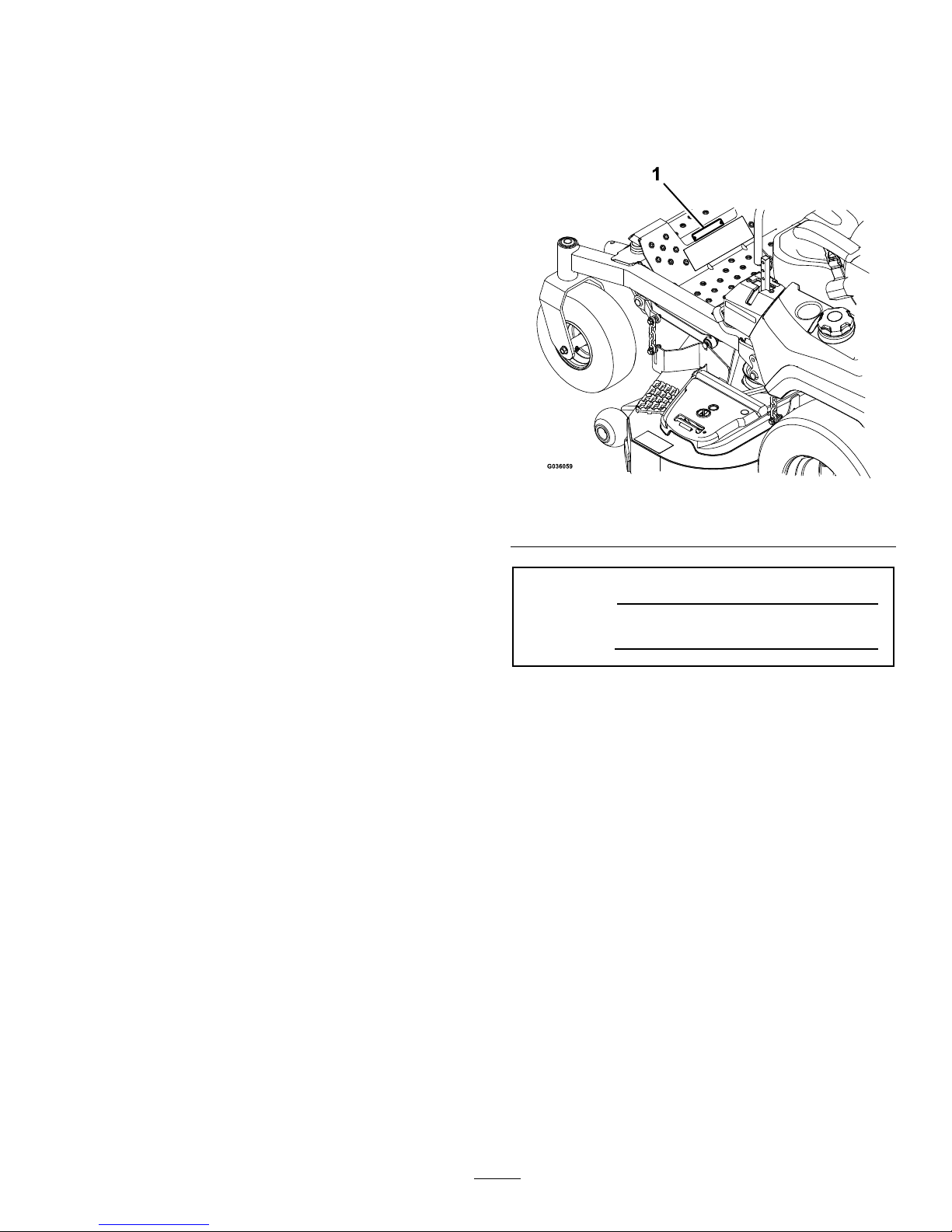
106-5517
1.Warning—donottouchthehotsurface.
107-3069
1.Warning-thereisnorolloverprotectionwhentherollbar
isdown.
2.Toavoidinjuryordeathfromarolloveraccident,keep
therollbarinthefullyraisedandlockedposition
andweartheseatbelt.Lowertherollbaronlywhen
absolutelynecessary;donotweartheseatbeltwhen
therollbarisdown.
3.ReadtheOperator’smanual;driveslowlyandcarefully.
11
Page 12
Safety
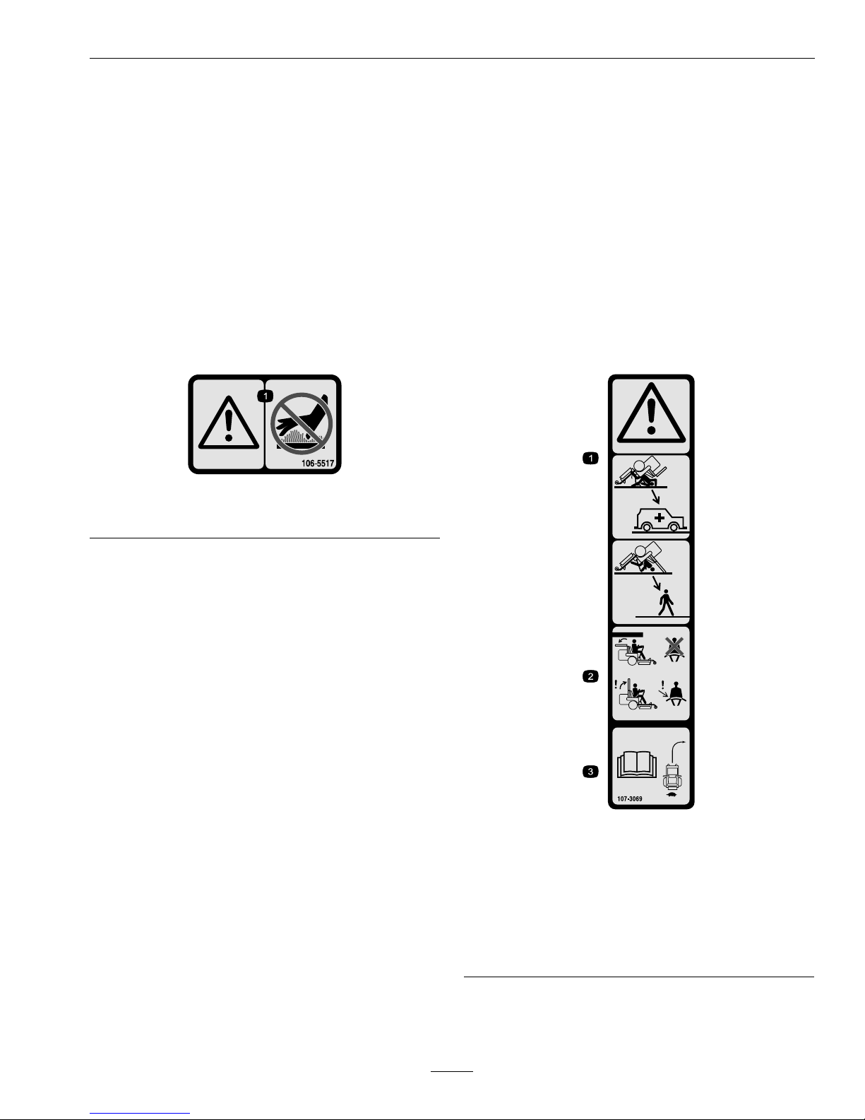
109-6014
109-6035
SideDischargeUnitsOnly
109-6036
1.ReadtheOperator’smanual
2.Removetheignitionkeyandreadtheinstructionsbefore
servicingorperformingmaintenance.
3.Heightofcut
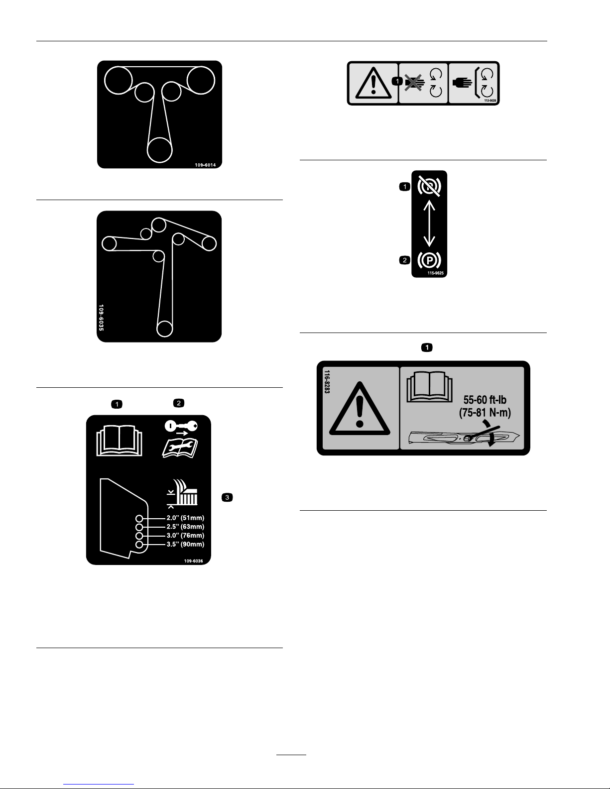
112-9028
1.Warning—stayawayfrommovingparts;keepallguards
inplace.
115-9625
1.Parking
brake—disengaged
2.Parkingbrake—engaged
116-8283
1.Warning—readtheOperator'sManualforinstructions
ontorquingthebladebolt/nutto55-60ft-lb(75-81N-m).
12
Page 13
Safety
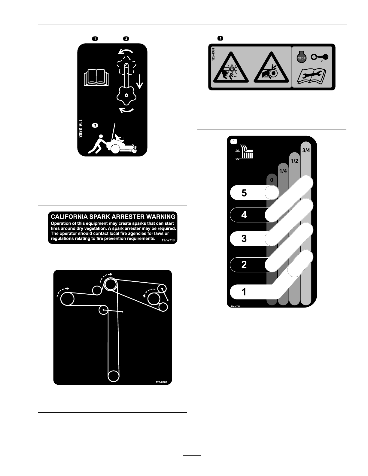
116-8588
1.ReadtheOperator’smanual.
2.Rotatethedrivereleaseknobtoloosen,slidetheknob,
andtighten.
3.Pushthemachine.
117-2718
126-0768
RearDischargeUnitsOnly
126-4363
1.Cutting/dismembermenthazard,fanandentanglement
hazard,belt—Stopengineandremovekeybefore
adjusting,servicingorcleaning.
126-4784
1.Heightofcut
13
Page 14
Safety
126-6464
SideDischargeUnits
1.Thrownobjectshazard
-keepbystandersa
safedistancefromthe
machine
3.Cutting/dismemberment
ofhandorfoot-stay
awayfrommovingparts;
keepallguardsand
shieldsinplace.
2.Thrownobjectshazard,
mower-donotoperate
withoutthedeector,
dischargecoverorgrass
collectionsystemin
place.
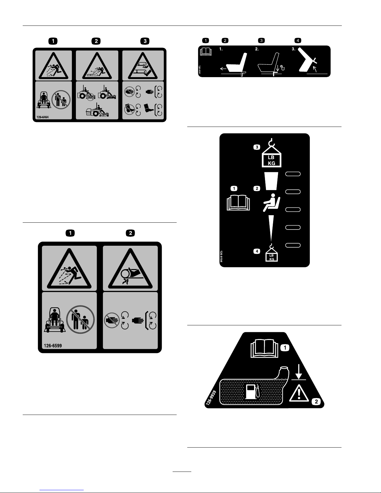
126-6599
RearDischargeUnits
1.Thrownobjectshazard
-keepbystandersa
safedistancefromthe
machine.
2.Cutting/dismemberment
ofhand-stayawayfrom
movingparts;keepall
guardsandshieldsin
place.
126-8161
X-SeriesUnits
1.ReadOperator’smanual
3.Pressdownonlatchto
unlockseat
2.Slideseatforward
4.Rotateseat
126-8194
S-SeriesUnits
1.ReadtheOperator’s
manual
3.Firmestposition/operator
200lb(91kg)andover
2.Seatadjustment4.Softestposition/operator
lessthan200lb(91kg)
126-9939
1.ReadtheOperator’s
Manual
2.Filltobottomofller
neck;warning–donot
overllthetank
14
Page 15
Safety
131-1097
Exmark708ccEngineOnly
1.Oildrain
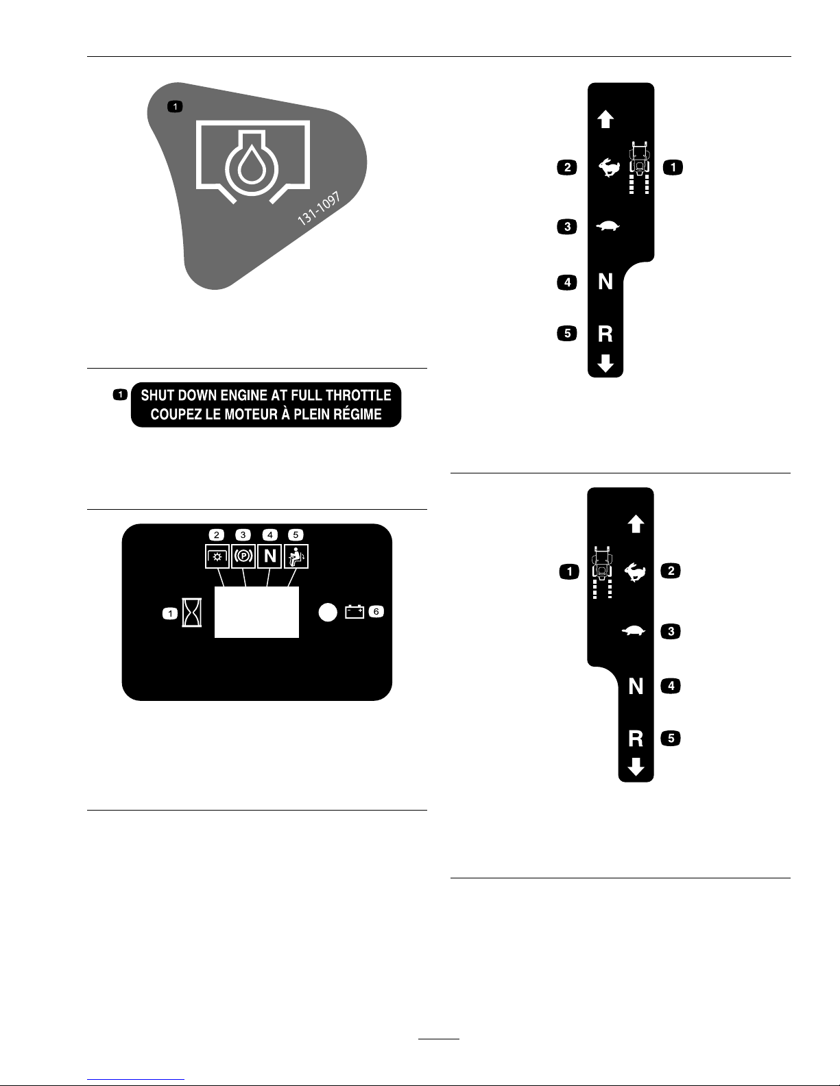
Exmark708ccEngineOnly
1.Shutdownengineatfullthrottle
MessageDisplay
1.Hour4.Neutral
2.PTO5.Operatorpresence
switch
3.Parkingbrake6.Battery
LHMotionControl
1.Machinespeed4.Neutral
2.Fast5.Reverse
3.Slow
RHMotionControl
1.Machinespeed4.Neutral
2.Fast5.Reverse
3.Slow
15
Page 16
Safety
PTOSwitchSymbols
1.PTO–disengage2.PTO–engage
TransportLock
1.Heightofcut
2.Pulluptounlockthe
transportlock
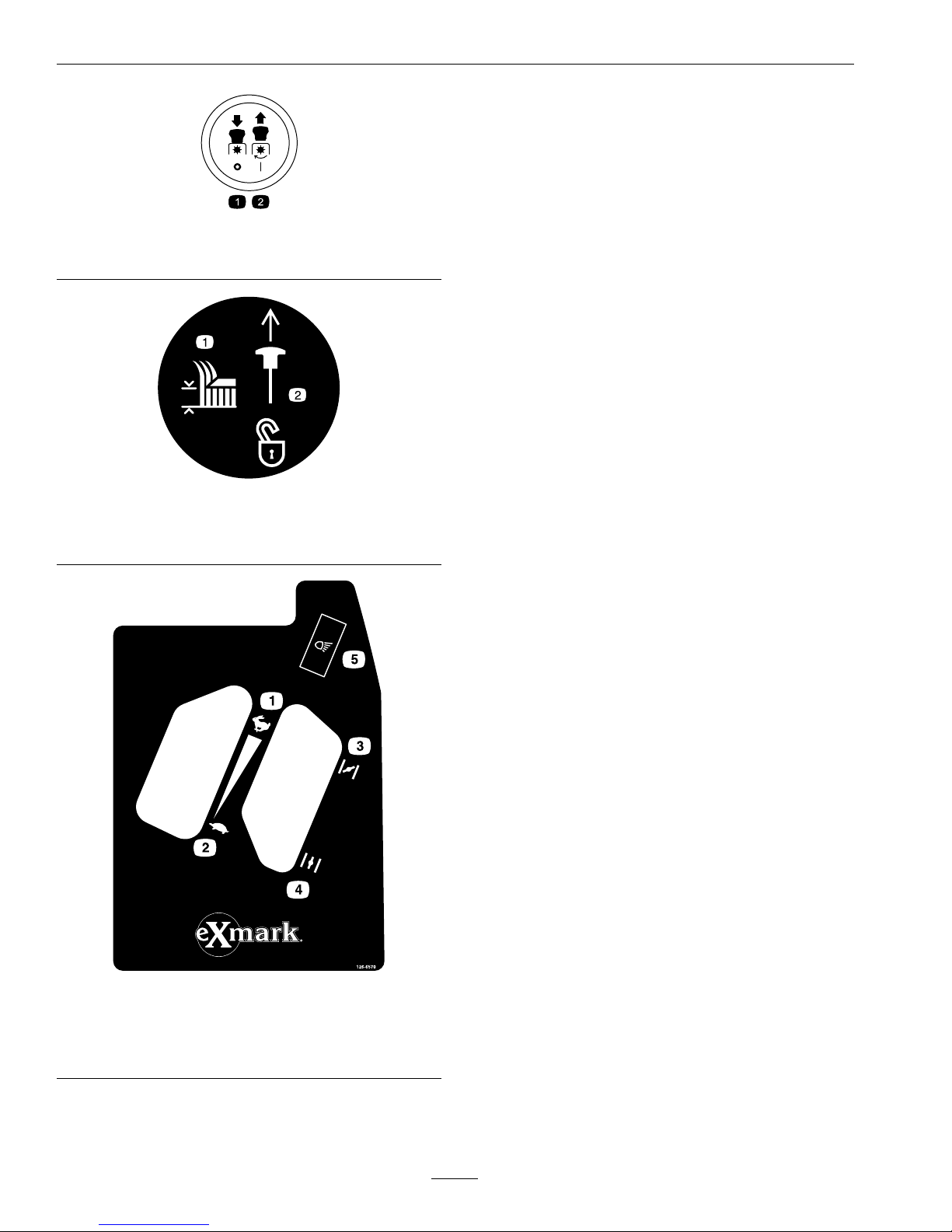
126-6570
1.Throttle-fast4.Choke-off
2.Throttle-slow
5.Optionallightaccessory
3.Choke-on
16
Page 17
Safety
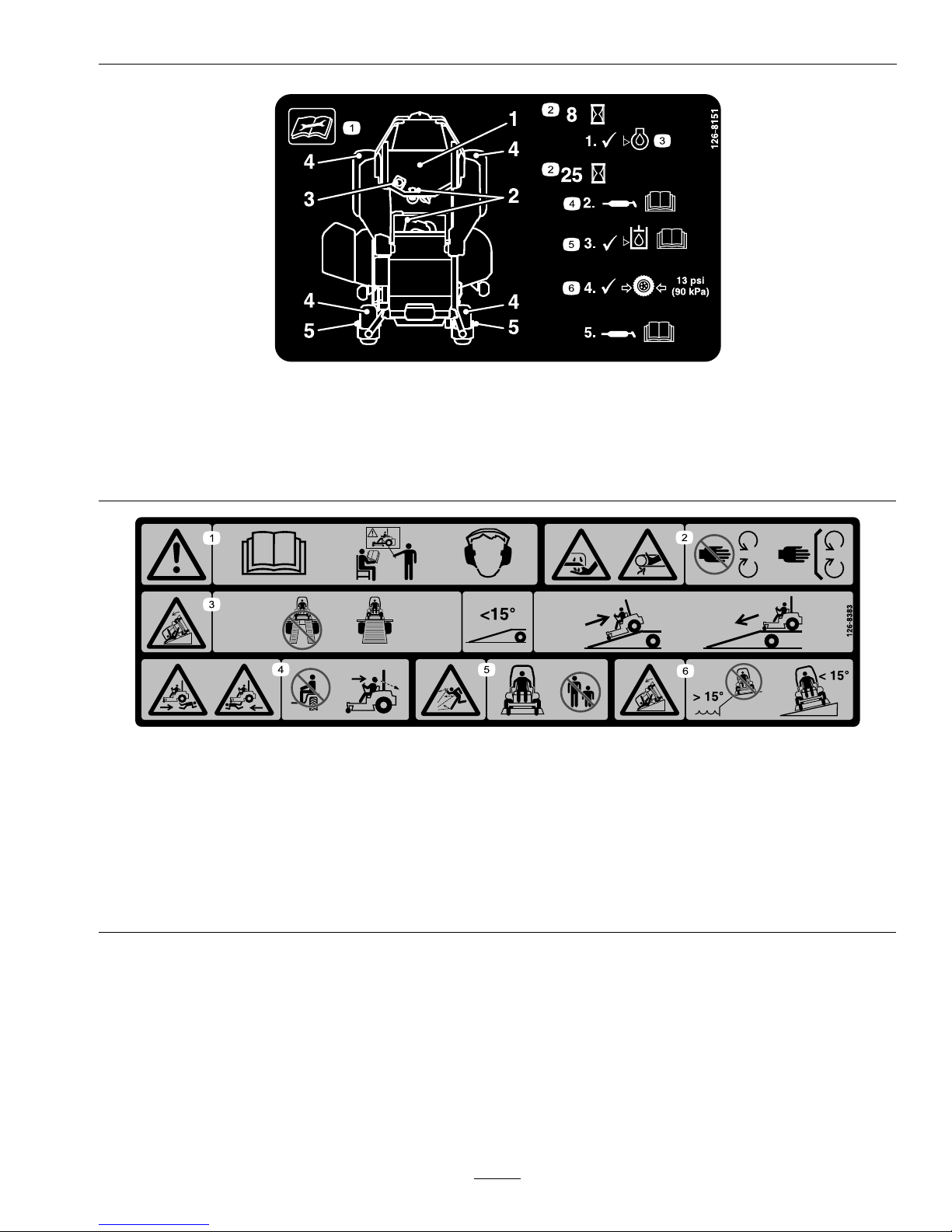
126-8151
1.Readtheinstructionsbeforeservicingorperforming
maintenance
4.RefertotheOperator'smanualforgreaseinstructions
2.Timeinterval
5.CheckhydraulicoillevelandrefertotheOperator's
manualorfurtherinstructions
3.Checkoillevel6.Checktirepressure
126-8383
1.Warning-ReadtheOperator’sManual.DoNotoperatethis
machineunlessyouaretrained.Wearhearingprotection.
4.Bodilyharmhazard-lookbehindyouwhenmowingin
reverse.
2.Cuttingandpinchinghazard-keephandsandfeetaway
frommovingparts;keepallguardsandshieldsinplace.
5.Thrownobjecthazard-keepbystandersaway.
3.Ramphazard-whenloadingontoatrailer,donotuse
dualramps;onlyuseasingularrampwideenoughforthe
machineandthathasaninclinelessthan15degrees;
backuptheramp(inreverse)anddriveforwardoffthe
ramp.
6.Tippinghazardonslopes-donotuseonslopesnearopen
water;donotuseonslopesgreaterthan15degrees.
17
Page 18

Specications
Specications
Systems
Engine
•EngineSpecications:SeeyourEngineOwner’s
Manual
•EngineOilType:Exmark4–CyclePremium
EngineOil
•RPM:
–X-andS-Series:FullSpeed:3750±50RPM
(PTOnotengaged)Idle:1500±100RPM
–E-Series:FullSpeed:3600±50RPM(PTO
notengaged)Idle:1500±100RPM
FuelSystem
•Capacity:7.0gal.(26.5L)
•FuelRecommendations:
–Forbestresults,useonlyclean,fresh,unleaded
gasolinewithanoctaneratingof87orhigher
((R+M)/2ratingmethod).
–Oxygenatedfuelwithupto10%ethanolor
15%MTBEbyvolumeisacceptable.
–DoNotuseethanolblendsofgasoline(such
asE15orE85)withmorethan10%ethanol
byvolume.Performanceproblemsand/or
enginedamagemayresultwhichmaynotbe
coveredunderwarranty.
–DoNotusegasolinecontainingmethanol.
–DoNotstorefueleitherinthefueltankor
fuelcontainersoverthewinterunlessafuel
stabilizerisused.
–DoNotaddoiltogasoline.
•FuelFilter:
Kohler:KohlerP/N2405013
Kawasaki:KawasakiP/N49019-0014
ExmarkEngine:ExmarkP/N133-1563
•FuelShut-OffValve:
AllUnits:1/4turn(“ON”,“OFF”).
ElectricalSystem
•ChargingSystem:FlywheelAlternator
•ChargingCapacity:15amps
•BatteryType:BCIGroupU1
•RecommendedMinimumBatteryCCA:260CCA
•BatteryVoltage:12Volt
•Polarity:NegativeGround
•Fuses:
Allunits:
–20ampchargingsystemfuse
(notusedonKohlerengines)
–15ampmainfuse
SafetyInterlockSystem
•LCDindicatorsappearforthePTO ,parkbrake,
drivelevers,andoperatorpresenceinthemessage
displayontheRHcontrolpanel.
•PTOmustbedisengaged,brakeengaged,and
motioncontrolleversout(neutrallock)tostart
engine.(Itisnotnecessaryfortheoperatortobe
intheseattostarttheengine.)
•OperatormustbeinseatwhenPTOisengaged,
brakeisdisengaged,ormotioncontrolleversare
movedinorenginewillstop.
•Enginewillstopifeithertheleft,theright,or
bothleversaremovedfromneutrallockposition
whilebrakeisengaged.
OperatorControls
•SteeringandMotionControl:
Note:Motioncontrolleversareadjustableto
threeheights.
–Separatelevers,oneachsideoftheconsole,
controlspeedanddirectionoftravelofthe
respectivedrivewheels.
–Steeringiscontrolledbyvaryingtheposition
oftheleversrelativetoeachother.
–Movingmotioncontrolleversoutward(in
slots)locksthedrivesysteminneutral.
•PTOEngagementSwitch:Engageselectricclutch
(todrivebelt)whichengagesmowerblades.
•ParkingBrakeLever:Engagesparkingbrake.
•DeckHeightAdjustmentLever:Setscutting
heighttodesiredposition.
•DeckLiftPedal:Footpedalthatliftsdeck.
•TransportLock:Latchingposition:Automatically
latchesatthetransportposition.
18
Page 19

Specications
Seat
•SeatType:
–X-Series:
Deluxesuspension(adjustablespring
suspension)seatwithhighback,moldedfoam
ip-uparmrests,andintegralsafetyswitch.
–S-Series:
Standardseatwithfoampaddedseatcushion
witharmrests,integralsafetyswitch,and
adjustableSeatIsolationSystemsuspension
forreducedvibrationandenhancedride.
–E-Series:
Standardseatwithfoampaddedseatcushion
witharmrestsandintegralsafetyswitch.
•Mounting:
–X-andS-Series:Hingedseatframetotiltup
seat.Adjustableforeandaftonseattracks.
–E-Series:Adjustableforeandaftonseat
tracks.
•Armrests:Moldedip-uparmrests.
•SeatSafetySwitch:Integratedseatswitch.
Timedelayseatswitcheliminatesroughground
cut-outs.
HydrostaticGroundDriveSystem
•Twounitizedhydrostatictransmissions:
–X-Series:
HydroGearZT3400
–S-Series:
◊Unitswithsidedischargedecks:
HydroGearZT3100
◊Unitswithreardischargedeck:
HydroGearZT3400
–E-Series:
◊Unitswith48or52inchdecks:
HydroGearZT2800
◊Unitswith60inchdeck:
HydroGearZT3100
•HydraulicOilType:ExmarkPremiumHydroOil.
•HydraulicOilCapaczity:77oz(2.3L)perside
•HydraulicFilter:P/N109-3321
•Speeds:
–X-Series:
◊Forward:0-10mph(16.1km/hr)forward.
◊Reverse:0-7mph(11.3km/hr)reverse.
–S-Series:
◊Forward:0-9mph(14.5km/hr)forward.
◊Reverse:0-6mph(9.7km/hr)reverse.
–E-Series:
◊Forward:0-8mph(12.9km/hr)
◊Reverse:0-5mph(8.0km/hr)reverse.
•Drivewheelreleasevalvesallowmachinetobe
movedwhenengineisnotrunning.
Tires&Wheels
X-Series:
Drive
Pneumatic(Airlled)
DeckSize
48&5260
Quantity
22
Tread
K500K500
Size24x9.50-1224x10.5-12
PlyRating
44
Pressure
13psi(90kPa)13psi(90kPa)
S-Series:
Drive
Pneumatic(Airlled)
DeckSize
48&5260
Quantity
22
Tread
K500K500
Size23x9.50-1223x10.50-12
PlyRating
44
Pressure
13psi(90kPa)13psi(90kPa)
19
Page 20

Specications
E-Series:
Drive
Pneumatic(Airlled)
DeckSize
48&5260
Quantity
22
Tread
K500K500
Size22x9.50-1222x10.50-12
PlyRating
44
Pressure
13psi(90kPa)13psi(90kPa)
FrontCaster—AllModels
Pneumatic(Airlled)
DeckSize
AllModels
Quantity
2
Tread
Smooth
Size13x6.50-6
PlyRating
4
Pressure
13psi(90kPa)
CuttingDeck
•CuttingWidth:
–48inchDeck:(121.9cm)
–52inchDeck:(132.1cm)
–60inchDeck:(152.4cm)
•Discharge:
–SideDischarge:Non“R”models
–RearDischarge:“R”models
•BladeSize:
–48inchDeck:16.25inches(41.3cm)–(3ea.)
–52inchDeck:18.00inches(45.7cm)–(3ea.)
–60inchDeck:20.50inches(52.1cm)–(3ea.)
•BladeSpindles:
–X-Series:Solidsteelspindleswith.98inch(25
mm)I.D .bearings.
–S-andE-Series:Solidsteelspindleswith.67
inch(17mm)I.D.bearings.
•DeckDrive:“B”Sectionbeltwithself-tensioning
idler.
•Electricclutch:
–48&52InchDecks:125ft-lbMagStop
–60InchDeck:125ft-lbNeo-MagStop
•Deck:Fulloatingdeckisattachedtoout-front
supportframe.Anti-scalprollersprovide
maximumturfprotection.Deckdesignallowsfor
bagging,mulchingorsidedischarge.
–48inchDeck:3anti-scalprollers
–52inchDeck:5anti-scalprollers
–60inchDeck:5anti-scalprollers
–60inchDeck-RearDischarge:
4anti-scalprollers
–SideDischarge:Fulloatingdeckisattached
toout-frontsupportframe.Anti-scalprollers
providemaximumturfprotection.Deck
designallowsforbagging,mulchingorside
discharge.
–RearDischarge:Fulloatingdeckisattached
toout-frontsupportframe.Anti-scalprollers
andsidebumpersprovidemaximumturf
protection.Deckdesignallowsforrear
dischargeornishcut(reduceddischarge).
•DeckDepth:
–S-andE-Series:
◊SideDischarge:5.0inches(12.7cm)
◊RearDischarge:5.5inches(14.0cm)
–X-Series:
AllDecks:5.5inches(14.0cm)
•CuttingHeightAdjustment:
Footactivatedleverisusedtoadjustthecutting
heightfrom11/2inch(3.8cm)to5inches(12.7
cm)in1/4inch(6.4mm)increments.
•MulchingKit:Optional.
20
Page 21

Specications
Dimensions
OverallWidth:
X-Series—SideDischargeUnits:
48inch
Deck
52inch
Deck
60inch
Deck
Without
Deck
47.4inches
(120.4cm)
48.7inches
(123.7cm)
52.1inches
(132.3cm)
Deector
Up
52.6inches
(133.6cm)
57.3inches
(145.5cm)
61.7inches
(156.7cm)
Deector
Down
59.5inches
(151.1cm)
64.6inches
(164.1cm)
72.7inches
(184.7cm)
S-Series—SideDischargeUnits:
48inch
Deck
52inch
Deck
60inch
Deck
Without
Deck
47.2inches
(119.9cm)
48.5inches
(123.2cm)
51.4inches
(130.6cm)
Deector
Up
52.6inches
(133.6cm)
57.3inches
(145.5cm)
61.7inches
(156.7cm)
Deector
Down
59.5inches
(151.1cm)
64.3inches
(163.3cm)
72.3inches
(183.6cm)
E-Series—SideDischargeUnits:
48inch
Deck
52inch
Deck
60inch
Deck
Without
Deck
46.7inches
(118.6cm)
48.0inches
(121.9cm)
51.2inches
(130.0cm)
Deector
Up
52.6inches
(133.6cm)
57.3inches
(145.5cm)
61.7inches
(156.7cm)
Deector
Down
59.5inches
(151.1cm)
64.3inches
(163.3cm)
72.3inches
(183.6cm)
RearDischargeUnits:
60inchDeck
WithoutDeck51.4inches
(130.6cm)
WithDeck66.0inches
(167.6cm)
OverallLength:
SideDischargeUnits:
48inchDeck52inchDeck60inchDeck
81.7inches
(207.5cm)
81.7inches
(207.5cm)
82.2inches
(208.8cm)
RearDischargeUnits:
60inchDeck
84.3inches
(214.1cm)
OverallHeight:
X-Series—SideDischargeUnits
RollBar-UpRollBar-Down
70.4inches(178.8cm)48.4inches(122.9cm)
S-Series—SideDischargeUnits
RollBar-UpRollBar-Down
70.2inches(178.3cm)48.9inches(124.2cm)
E-Series—SideDischargeUnits
RollBar-UpRollBar-Down
69.7inches(177.0cm)47.0inches(119.4cm)
RearDischargeUnits
RollBar-UpRollBar-Down
70.2inches(178.3cm)48.9inches(124.2cm)
21
Page 22

Specications
TreadWidth:(CentertoCenterof
Tires,Widthwise)
X-Series—SideDischargeUnits
48inch
Deck
52inch
Deck
60inch
Deck
Drive
Wheels
37.7inches
(95.8cm)
39.0inches
(99.1cm)
40.7inches
(103.4cm)
Caster
Wheels
33.1inches
(84.1cm)
33.1inches
(84.1cm)
38.2inches
(97.0cm)
S-Series—SideDischargeUnits
48inch
Deck
52inch
Deck
60inch
Deck
Drive
Wheels
37.7inches
(95.8cm)
39.0inches
(99.1cm)
40.7inches
(103.4cm)
Caster
Wheels
33.1inches
(84.1cm)
33.1inches
(84.1cm)
38.2inches
(97.0cm)
E-Series—SideDischargeUnits
48inch
Deck
52inch
Deck
60inch
Deck
Drive
Wheels
37.7inches
(95.8cm)
39.0inches
(99.1cm)
40.7inches
(103.4cm)
Caster
Wheels
33.1inches
(84.1cm)
33.1inches
(84.1cm)
38.2inches
(97.0cm)
RearDischargeUnits:
60inchDeck
DriveWheels40.7inches
(103.4cm)
CasterWheels31.0inches
(78.7cm)
WheelBase:(CenterofCasterTireto
CenterofDriveTire)
SideDischargeUnits:
48inchDeck52inchDeck60inchDeck
49.7inches
(126.2cm)
49.7inches
(126.2cm)
50.2inches
(127.5cm)
RearDischargeUnits:
60inchDeck
52.3inches
(132.8cm)
CurbWeight:
Unitswith48InchSide
DischargeDecks
849-937lb
(385-425kg)
Unitswith52InchSide
DischargeDecks
862-957lb
(391–434kg)
Unitswith60InchSide
DischargeDecks
901-1006lb
(409-456kg)
Unitswith60InchRear
DischargeDecks
1012lb(459kg)
22
Page 23
ProductOverview
TorqueRequirements
BoltLocation
Torque
X-Series:
BladeDriveSheave
MountingNut
130-160ft-lb(176-217N-m)
S-andE-Series:
BladeDriveSheave
MountingNut
75-85ft-lb(102-115N-m)
BladeMounting
Bolt(lubricatewith
anti-seize)
50-60ft-lb(68-81N-m)
Anti-ScalpRoller
NylocNut—Side
DischargeUnitsOnly
(SeeFigure18)
50-55ft-lb(68-75N-m)
Anti-ScalpRoller
NylocNut—Rear
DischargeUnitsOnly
(SeeFigure19)
30-35ft-lb(41-47N-m)
EngineMountingBolts
27-33ft-lb(37-45N-m)
WheelLugNuts
90-100ft-lb(122-136N-m)
RolloverProtection
System(RollBar)1/2
inchMountingBolts
90-100ft-lb(122-136N-m)
ClutchRetaining
Bolt(securedwith
threadlocker)
49-61ft-lb(66-83N-m)
RearDischargeSide
Bumpers
10-12ft-lb(14-16N-m)
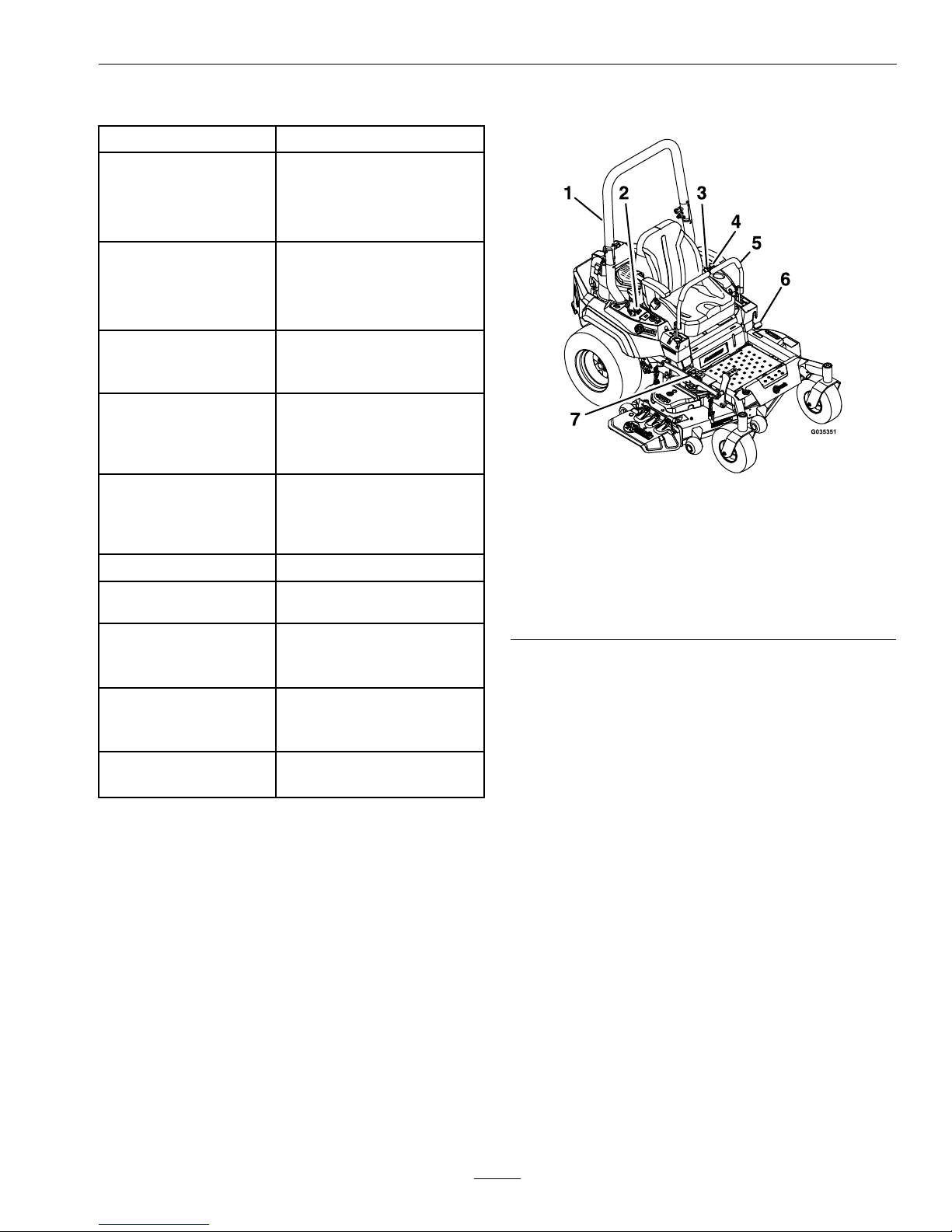
ProductOverview
Figure4
1.RolloverProtection
System(ROPS)
5.Motioncontrollevers
2.EngineControls(right
console)
6.Parkingbrake
3.Seatbelt7.Heightofcutadjustment
4.Fuelcap
23
Page 24
Operation
Operation
Note:Determinetheleftandrightsidesofthe
machinefromthenormaloperatingposition.
Controls
MotionControlLevers
Themotioncontrolleversarelocatedoneachside
oftheconsoleandcontroltheforwardandreverse
motionofthemachine.
Movingtheleversforwardorbackwardturns
thewheelonthesamesideforwardorreverse
respectively.Wheelspeedisproportionaltothe
amounttheleverismoved.
Movingtheleversoutwardfromthecenterposition
intotheT-slotlocksthemintheneutralposition
(Figure5).
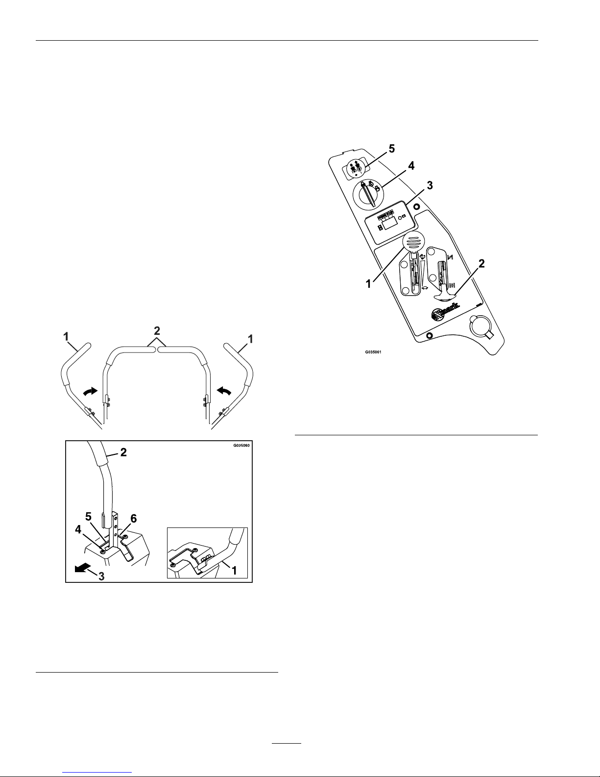
Figure5
1.Neutrallockposition
(handlesout)
4.Forward
2.Neutraloperateposition
(handlesin)
5.Neutral(operate)
3.Frontofunit
6.Reverse
ChokeControl
Locatedonrightconsole(blacklever)(seeFigure6).
Thechokeisusedtoaidinstartingacoldengine.
Movingthechokeleverforwardwillputthechokein
the“ON”positionandmovingthechokelevertothe
rear,tothedetent,willputthechokeinthe“OFF”
position.DoNotrunawarmenginewithchokein
the“ON”position.
Figure6
1.Throttlelever4.Ignitionswitch
2.Chokelever
5.Bladecontrolswitch
(powertake-off)
3.Hourmeter
ThrottleControl
Locatedonrightconsole(redlever)(seeFigure6).
Thethrottleisusedtocontrolenginespeed.Moving
thethrottleleverforwardwillincreaseenginespeed
andmovingthethrottlelevertotherearwilldecrease
enginespeed.Movingthethrottleforwardintothe
detentisfullthrottle.
BrakeLever
Locatedonleftsideofunit,justtothefrontofthe
LHmotioncontrollever.
Thebrakeleverengagesaparkingbrakeonthedrive
wheels.
Pulltheleverupandrearwardtoengagethebrake.
Pushtheleverforwardanddowntodisengagethe
brake.
24
Page 25
Operation
Theunitmustbetieddownandbrakeengagedwhen
transporting.
IgnitionSwitch
Locatedonrightconsole(seeFigure6).
Theignitionswitchisusedtostartandstopthe
engine.Theswitchhasthreepositions“OFF”,“ON”
and“START”.Insertkeyintoswitchandrotate
clockwisetothe“ON”position.Rotateclockwiseto
thenextpositiontoengagethestarter(keymustbe
heldagainstspringpressureinthisposition).Allow
thekeytoreturntothe“ON”positionimmediately
aftertheenginestarts.
Figure7
1.Off3.Start
2.On
Note:Brakemustbeengaged,motioncontrol
leversout(neutrallockposition)andPTOswitch
disengagedtostartengine.(Itisnotnecessaryforthe
operatortobeintheseattostarttheengine.)
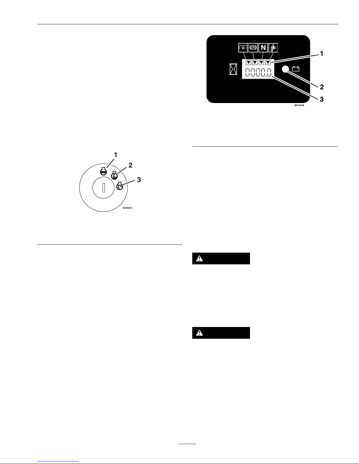
HourMeter
Locatedonthecontrolpanel(seeFigure6and
Figure8).
Thehourmeterrecordsthenumberofhoursthat
theenginehasrun.
Figure8
1.LCDindicators3.Hour/Voltagedisplay
2.Lowvoltageindicator
light
FuelShut-OffValve
LocatedbythelowerLHROPStubemounting.
Thefuelshut-offvalveisusedtoshutoffthefuel
whenthemachinewillnotbeusedforafewdays,
duringtransporttoandfromthejobsite,andwhen
parkedinsideabuilding.
Alignvalvehandlewiththefuellinetoopen.Rotate
90°toclose.
DriveWheelReleaseValves
WARNING
Handsmaybecomeentangledintherotating
drivecomponentsbelowtheenginedeck,which
couldresultinseriousinjuryordeath.
Stopengine,removekey,allowallthemoving
partstostopbeforeaccessingthedrivewheel
releasevalves.
WARNING
Theengineandhydraulicdriveunitscanbecome
veryhot.T ouchingahotengineorhydraulic
driveunitscancausesevereburns.
Allowtheengineandhydraulicdriveunitsto
coolcompletelybeforeaccessingthedrivewheel
releasevalves.
Locatedontheleftandrightsidesunderneaththe
enginedeck.
Duringnormaloperatingconditions,thedrivewheel
releasevalvesarepositionedinfrontoftheslots.If
25
Page 26
Operation
themachinehastobepushedbyhand,thevalves
mustbeinthe“released”position(seeFigure9).
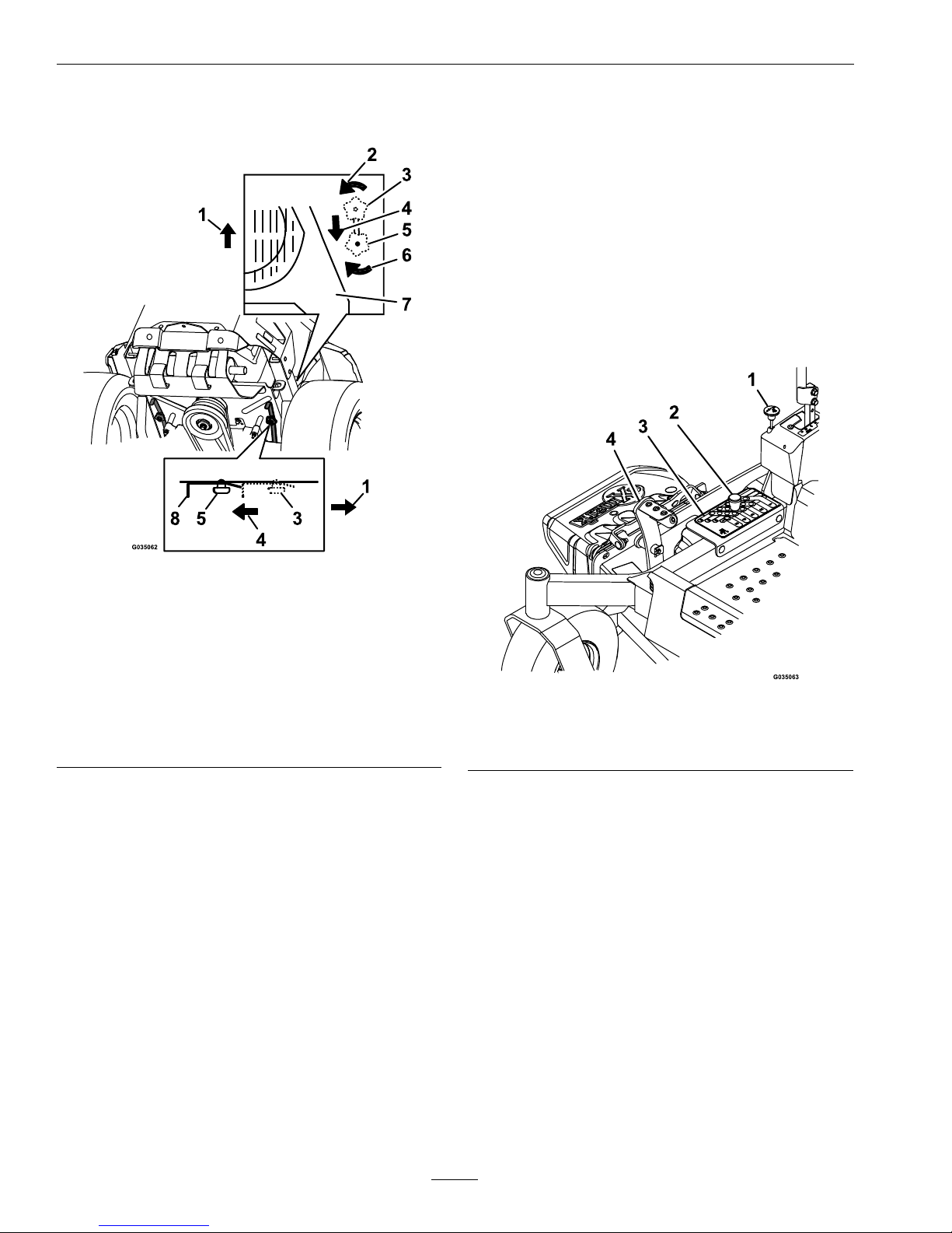
Figure9
1.Frontofthemachine
2.Rotatebypassreleaseknobcounterclockwisetoloosen
3.Leverpositionforoperatingthemachine
4.Pullleverinthisdirectiontopushthemachine
5.Leverpositionforpushingthemachine
6.Rotatebypassreleaseknobclockwisetotighten
7.Engine
8.Releaselever
Toreleasethedrivesystem(seeitem1inFigure9),
loosentheknobbyturningcounterclockwise.Then
pullthereleaseleverontheundersideofmachine
towardsthebackofthemachineandretightenthe
knobtoholdthereleaseleverbackinthereleased
state.Repeatthisoneachsideofthemachine.
Releasetheparkingbrake.Themachineisnowable
tobepushedbyhand.
Toresetthedrivesystem(seeitem2inFigure9),
loosentheknobbyturningcounterclockwise.Then
pushthereleaseleverontheundersideofmachine
towardsthefrontofthemachineandretightenthe
knobtoholdthereleaseleverintheoperatingstate.
Repeatthisoneachsideofthemachine.
DoNottowmachine.
PTOEngagementSwitch
Locatedonrightconsole(seeFigure6).
Switchmustbepulledout(up)toengagetheblades.
Switchispushedintodisengagetheblades.
DeckLiftPedal
Locatedattherightfrontcorneroftheoorpan.
Pushthepedalforwardwithyourfoottoraisethe
cuttingdeck.Allowthepedaltomoverearwardto
lowerthecuttingdecktothecutheightthathasbeen
set.
Figure10
1.Transportlockknob
3.Heightofcutdecal
2.Heightadjustmentpin
4.Deckfootpedal
TransportLock
LocatedonRHconsoleinfrontofthemotion
controllever(seeFigure10).
Thetransportlatchingmechanismwillautomatically
engagewhenthedeckisraisedtothetransport
position.Toreleasethedeckfromthetransport
position:pushthefootpedaltoremovetheload
fromthetransportlatchingmechanism,pullupon
thetransportlockknob,andletthepedalcomeback
tolowerthedeckdowntothedesiredcutheight.
Pre-Start
Fillfueltankonlevelground.SeeFuel
RecommendationsintheSpecicationssectionfor
additionalgasolineinformation.
26
Page 27

Operation
DoNotaddoiltogasoline.
DoNotoverllfueltank.Fillthefueltanktothe
bottomofthellerneck.Theemptyspaceinthe
tankallowsgasolinetoexpand.Overllingmayresult
infuelleakageordamagetotheengineoremission
system.
Makesureyouunderstandthecontrols,their
locations,theirfunctions,andtheirsafety
requirements.
RefertotheMaintenancesectionandperformallthe
necessaryinspectionandmaintenancesteps.
OperatingInstructions
RaisetheRolloverProtectionSystem
(ROPS)
Important:Therollbarisanintegraland
effectivesafetydevice.Keeptherollbarinthe
raisedandlockedpositionwhenoperatingthe
mower.Lowertherollbartemporarilyonlywhen
absolutelynecessary.
1.Theknobmustbecompletelylatchedwiththe
tabsinterlockingasshowninFigure11tolock
therollbarintheraised,operateposition.
2.Applyforwardpressuretotheupperhoopofthe
rollbar.
3.Pulltheknobandrotate90°toholdinthe
unlatchedpositiontolowertherollbar.
4.Toreturntotheoperateposition,raisetheroll
bar,andthenrotateknobs90°sothatthetabs
interlockpartially.Applyforwardpressuretothe
rollbarupperhoopandobservethattheknobs
returntothecompletelylatchedposition.
Figure11
1.Rollbarupperhoop
2.Knobin“latched”position
3.Pullknobtounlatch
4.Rotate90°toholdunlatched
5.Knobin“unlatched”position
5.Makesuretheknobsarefullyengagedwiththe
rollbarintheraisedposition.Theupperhoopof
therollbarmayneedtobepushedforwardor
pulledrearwardtogetbothknobsfullyengaged
(seeFigure12).
27
Page 28

Operation
Figure12
1.Engaged2.Partiallyengaged—Do
NotoperatewithROPS
inthiscondition.
Important:Alwaysusetheseatbeltwiththe
rollbarintheoperate(raised)position.Ensure
thattherearpartoftheseatissecuredwiththe
seatlatch.
OpentheFuelShut-OffValve
Rotatethevalveandalignwiththefuellinetoopen.
StartingtheEngine
1.Movethemotioncontrolleversouttotheneutral
lockposition.
2.Pullupandbackontheparkingbrakeleverto
engagetheparkingbrake.
3.PushdownonthePTOswitchtothe“disengage”
position.
Note:Itisnotnecessaryfortheoperatortobe
intheseattostarttheengine.
4.Placethethrottlemidwaybetweenthe“SLOW”
and“FAST”positions.
5.Onacoldengine,pushthechokeleverforward
intothe“ON”position.
Onawarmengine,leavethechokeinthe“OFF”
position.
6.Turnignitionswitchtothe“START”position.
Releasetheswitchassoonastheenginestarts.
Important:DoNotcranktheengine
continuouslyformorethantensecondsata
time.Iftheenginedoesnotstart,allowa60
secondcool-downperiodbetweenstarting
attempts.Failuretofollowtheseguidelines
canburnoutthestartermotor.
7.Ifthechokeisinthe“ON”position,gradually
returnchoketothe“OFF”positionastheengine
warmsup.
EngagingthePTO
DANGER
Therotatingbladesunderthemowerdeckare
dangerous.Bladecontactcancauseserious
injuryorkillyou.
DoNotputhandsorfeetunderthemoweror
mowerdeckwhenthebladesareengaged.
DANGER
Anuncovereddischargeopeningwillallow
objectstobethrowninanoperator’sor
bystander’sdirection.Also,contactwiththe
bladecouldoccur.Thrownobjectsorblade
contactcancauseseriousinjuryordeath.
Neveroperatethemowerwiththedischarge
deectorraised,removed,oralteredunlessthere
isagrasscollectionsystemormulchkitinplace
andworkingproperly.
ThePTOpush-pullswitchengagesthecuttingblades.
Besurethatallpersonsareclearofthemowerdeck
anddischargeareabeforeengagingPTO.
Important:Operatormustbeinseatbeforethe
PTOcanbeengaged.
1.Setthethrottlemidwaybetweenthe“SLOW”and
“FAST”positions.
2.PullthePTOswitchoutwardtoengagetheblades.
3.Placethethrottleinthe“FAST”positiontobegin
mowing.
DisengagingthePTO
1.Setthethrottlemidwaybetweenthe“SLOW”and
“FAST”positions.
2.PushthePTOswitchintodisengagetheblades.
StoppingtheEngine
1.Bringtheunittoafullstop.
28
Page 29

Operation
2.Movethemotioncontrolleversouttotheneutral
lockposition.
3.Engagetheparkingbrake.
4.Placethethrottlemidwaybetweenthe“SLOW”
and“FAST”positions.
5.DisengagethePTO .
6.Allowtheenginetorunforaminimumof15
seconds,thenturntheignitionswitchtothe
“OFF”positiontostoptheengine.
7.Removethekeytopreventchildrenorother
unauthorizedpersonsfromstartingengine.
8.Closethefuelshut-offvalvewhenthemachine
willnotbeinuseforafewdays,when
transporting,orwhentheunitisparkedinside
abuilding.
DrivingtheMachine
CAUTION
Machinecanspinveryrapidlybypositioningone
levertoomuchaheadoftheother.Operatormay
losecontrolofthemachine,whichmaycause
damagetothemachineorinjury.
•Usecautionwhenmakingturns.
•Slowthemachinedownbeforemakingsharp
turns.
Important:Tobeginmovement(forwardor
backward)theoperatormustbeintheseat,the
brakelevermustbedisengaged(pusheddown)
beforethemotioncontrolleverscanbemovedin
ortheenginewillstop.
Whenthemotioncontrolleversarepositionedfully
outward(apart)intheT-slot,thedrivesystemisin
theneutrallockposition(Figure12).
Whenthemotioncontrolleversaremoveddirectly
inward(together)thedrivesystemisintheneutral
operateposition.
Figure13
1.Neutrallockposition
(handlesout)
4.Forward
2.Neutraloperateposition
(handlesin)
5.Neutral(operate)
3.FrontofUnit
6.Reverse
DrivingForward
1.Releasetheparkingbrake.
2.Movethemotioncontrolleversinwardtothe
centertotheneutralposition.
3.Tomoveforwardinastraightline,moveboth
leversforwardwithequalpressure.
29
Page 30

Operation
Figure14
Toturnleftorright,pullthemotioncontrollever
backtowardneutralinthedesiredturndirection.
Themachinewillmovefasterthefartherthe
motioncontrolleversaremovedfromtheneutral
position.
4.Tostop,positionbothmotioncontrolleversin
theneutraloperateposition.
DrivinginReverse
1.Movethemotioncontrolleversinwardtothe
neutraloperateposition.
2.Tomoverearwardinastraightline,moveboth
leversrearwardwithequalpressure.
Figure15
Toturnright,releasepressureontheRHmotion
controlleverandtherearofthemachinewill
movetowardstherearandtotheright.
Toturnleft,releasepressureontheLHmotion
controlleverandtherearofthemachinewill
movetowardstherearandtotheleft.
3.Tostop,positionbothmotioncontrolleversin
theneutraloperateposition.
AdjustingtheCuttingHeight
Thecuttingheightofthemowerdeckisadjusted
from11/2to5inches(3.8cmto12.7cm)in1/4
inch(6.4mm)increments.
1.Stopthemachineandmovethemotioncontrol
leversoutwardtotheneutrallockedposition.
2.DisengagethePTO .
3.Raiseandlockthedecktothetransportposition
(Figure16).
Thedeckisraisedbypushingthefootoperated
deckliftpedalforward.Thepedalislocatedatthe
frontrightcorneroftheoorpan.
Note:Whenchangingthecuttingheight
positions,alwayscometoacompletestop
anddisengagethePTO.
Figure16
1.Transportlockknob
3.Heightofcutdecal
2.Heightadjustmentpin
4.Deckfootpedal
4.Inserttheheightadjustmentpinintothehole
correspondingtothedesiredcuttingheight.
30
Page 31

Operation
Seethedecalonthetopofthedeckliftplatefor
cutheights.
5.Pushthefootleverforward,pulluponthe
transportlockknobandletthedecklower
downtothepredeterminedcutheightbyslowly
decreasingfootpressureallowingthefootlever
totravelrearward.
AdjustingtheAnti-ScalpRollers
Itisrecommendedtochangetheanti-scalproller
position,whentheheightofcuthaschanged.
1.Stopthemachineandmovethemotioncontrol
leversoutwardtotheneutrallockedposition.
2.DisengagethePTO .
3.Engagetheparkbrake.
4.Stoptheengine,removethekeyandwaitforall
movingpartstostop.
5.Afteradjustingtheheightofcut,adjustthe
anti-scalprollersbyremovingthemounting
hardware.
6.Placetherollersinoneofthepositionsshown
(Figure17).Rollerswillmaintain3/4inch(19
mm)clearancetothegroundtominimizegouging
androllerwearordamage.
Figure17
Forcuttingheightsabove3.5inches(90mm)usethe
bottomhole.Therollerswillstillbeeffectiveagainst
scalping.
1.Anti-scalproller
mountingbracket
2.Cuttingheight
ForMaximumDeckFlotation,placetherollers
oneholepositionlower.Rollersshouldmaintain
1/4inch(6.4mm)clearancetotheground.Do
Notadjusttherollerstosupportthedeck.
7.Reinstallthemountinghardware.
•SideDischargeUnits:
A.Besuretherollerboltsareinstalledwith
thespringdiscwasherbetweenthehead
oftheboltandthemountingbracket(see
Figure18).
B.Torquethe3/8nylocnutto50–55ft-lb
(68-75N-m).
Figure18
1.3/8-16X33/4inch
Grade8bolt
3.Frontrightanti-scalp
bracketshown
2.Springdiscwasher
(conetowardsbolthead)
4.3/8inchnyloc-torqueto
50-55ft-lb(68-75N-m)
31
Page 32

Operation
•RearDischargeUnits:
Torquethe3/8nylocnutto30-35ft-lb(41-47
N-m)(seeFigure19).
Figure19
1.3/8inchnyloc-torqueto
50-55ft-lb(68-75N-m)
3.Wheelspacer
2.Anti-scalprollers
4.3/8-16X73/8inchbolt
Note:Thefootoperateddeckliftassistlevercanbe
usedtomomentarilyliftthedecktoclearobjects.Be
surethatPTOisdisengaged.
AdjustingtheSideBumpers
(RearDischargeUnitsOnly)
Mountthesidebumpersinthetopholeswhen
operatinginheightofcutshigherthan21/2inches
(64mm)andinthecenterholeswhenoperatingin
heightofcutslowerthan21/2inches(64mm).
Note:Whenbumpersbecomeworn,switchthe
bumperstotheoppositesidesofthemower,ipping
themover.Thisallowsthebumperstobeusedlonger
beforereplacingthem.
1.Stopthemachineandmovethemotioncontrol
leversoutwardtotheneutrallockedposition.
2.DisengagethePTO .
3.Engagetheparkbrake.
4.Stoptheengine,removethekeyandwaitforall
movingpartstostop.
5.Positionthetransportlockinthelatching
position.
6.Removetheboltsandnutsfromeachbumper.
Figure20
1.Bolt3.Nut
2.Bumper
7.Moveeachbumpertothedesiredpositionand
securethemwiththeboltsandnuts.
Note:Onlyusethetoporcentersetsofholesto
adjustthebumpers.Thebottomholesareused
whenswitchingsides,atwhichtimetheybecome
thetopholesontheothersideofthemower.
Transporting
TransportingtheMachine
Useaheavy-dutytrailerortrucktotransportthe
machine.Ensurethatthetrailerortruckhasall
necessarylightingandmarkingasrequiredbylaw .
Thoroughlyreadallofthesafetyinstructions.
Knowingthisinformationcouldhelpyou,your
family,pets,orbystandersavoidinjury.
Totransportthemachine:
•Lockthebrakeandblockthewheels.
•Besurethefuelshut-offvalveisclosed.
•Securelyfastenthemachinetothetraileror
truckwithstraps,chains,cable,orropes.Only
usethefourdesignatedtie-downlocationson
themower–twoontheleftsideandtwoonthe
right(seeFigure21).Usetheselocationseven
whentransportingthemowerwithanattached
accessory.Usingnon-designatedlocationsmay
causedamagetothemowerand/orattachment.
32
Page 33

Operation
Figure21
Rightsideshown
1.Tie-downlocation
•Secureatrailertothetowingvehiclewithsafety
chains.
WARNING
Drivingonthestreetorroadwaywithoutturn
signals,lights,reectivemarkings,oraslow
movingvehicleemblemisdangerousandcan
leadtoaccidentscausingpersonalinjury.
Donotdrivemachineonapublicstreetor
roadway.
LoadingtheMachine
Useextremecautionwhenloadingorunloading
machinesontoatraileroratruck.Useafull-width
rampthatiswiderthanthemachineforthis
procedure.Backuprampsanddriveforwarddown
ramps(Figure22).
g028043
Figure22
1.Backupramps
2.Driveforwarddown
ramps
Important:Donotusenarrowindividualramps
foreachsideofthemachine.
Ensuretherampislongenoughsothattheanglewith
thegrounddoesnotexceed15degrees(Figure23).
Onatground,thisrequiresaramptobeatleastfour
times(4X)aslongastheheightofthetrailerortruck
bedtotheground.Asteeperanglemaycausemower
componentstogetcaughtastheunitmovesfromthe
ramptothetrailerortruck.Steeperanglesmayalso
causethemachinetotiporlosecontrol.Ifloadingon
ornearaslope,positionthetrailerortrucksothatit
isonthedownsideoftheslopeandtherampextends
uptheslope.Thiswillminimizetherampangle.
WARNING
Loadingamachineontoatrailerortruck
increasesthepossibilityoftip-overandcould
causeseriousinjuryordeath.
•Useextremecautionwhenoperatinga
machineonaramp.
•EnsurethattheROPSisintheupposition
andusetheseatbeltwhenloadingor
unloadingthemachine.Ensurethatthe
ROPSwillclearthetopofanenclosedtrailer.
•Useonlyafull-widthramp;donotuse
individualrampsforeachsideofthemachine.
•Donotexceeda15-degreeanglebetweenthe
rampandthegroundorbetweentheramp
andthetrailerortruck.
•Ensurethelengthoframpisatleastfour
times(4X)aslongastheheightofthetrailer
ortruckbedtotheground.Thiswillensure
thatrampangledoesnotexceed15degrees
onatground.
•Backuprampsanddriveforwarddown
ramps.
•Avoidsuddenaccelerationordeceleration
whiledrivingthemachineonarampasthis
couldcausealossofcontroloratip-over
situation.
33
Page 34

Operation
g027996
5
1
2
6
Figure23
1.Full-widthrampin
stowedposition
4.Rampisatleastfour
times(4X)aslongasthe
heightofthetraileror
truckbedtotheground
2.Sideviewoffull-width
rampinloadingposition
5.H=heightofthetraileror
truckbedtotheground
3.Notgreaterthan
15degrees
6.Trailer
34
Page 35

Maintenance
Maintenance
Note:Determinetheleftandrightsidesofthemachinefromthenormaloperatingposition.
WARNING
Whilemaintenanceoradjustmentsarebeing
made,someonecouldstarttheengine.
Accidentalstartingoftheenginecouldseriously
injureyouorotherbystanders.
Removethekeyfromtheignitionswitch,engage
parkingbrake,andpullthewire(s)offthespark
plug(s)beforeyoudoanymaintenance.Also
pushthewire(s)asidesoitdoesnotaccidentally
contactthesparkplug(s).
WARNING
Theenginecanbecomeveryhot.Touchingahot
enginecancausesevereburns.
Allowtheenginetocoolcompletelybefore
serviceormakingrepairsaroundtheenginearea.
RecommendedMaintenanceSchedule(s)
MaintenanceService
Interval
MaintenanceProcedure
Aftertherst5hours
•Changetheengineoil(Exmark708ccEngine).
•Changetheengineoil(KohlerEngine).
•Changetheengineoil(KawasakiEngine).
Aftertherst75hours
•Changethehydrauliclteranduid.
Beforeeachuseordaily
•Checktheaircleanerfordirty,looseordamagedparts.
•Checktheengineoil(Exmark708ccEngine).
•Checktheengineoil(KohlerEngine).
•Checktheengineoil(KawasakiEngine).
•Checkthemowerblades.
•Checkthesafetyinterlocksystem.
•Checktherolloverprotectionssystems(rollbar)knobs.
•Checktheseatbelt.
•Checkforloosehardware.
•Checkthehydraulicoillevelintheexpansiontank.
•Cleantheengineandexhaustsystemarea.
•Cleanthegrassanddebrisbuild-upfromthemachineandcuttingdeck.
•Cleanthegrassbuild-upfromunderthecuttingdeck.
Every25hours
•Cleantheaircleanerfoamelement(moreoftenindusty ,dirtyconditions)(Exmark708cc
engine).
•Serviceorreplacetheaircleanerprecleaner(moreoftenunderextremelydusty,dirty
conditions)(Kohlerengine).
•Greasethefrontcasteraxles(S-andE-SeriesOnly).
Every50hours
•Servicetheaircleanerpaperelement(moreoftenunderextremelydusty ,dirty
conditions)(Kohlerengine).
•Checkthetirepressures.
•Checktheconditionofthebelts.
•Greasethedeckandpumpidlerpivot.
•Checksparkarrester(ifequipped).
35
Page 36

Maintenance
MaintenanceService
Interval
MaintenanceProcedure
Every100hours
•Servicetheaircleanerpaperelement(moreoftenindusty ,dirtyconditions)(Exmark
708ccengine).
•Replacetheaircleanerfoamelement(moreoftenindusty,dirtyconditions)(Exmark
708ccengine).
•Replacetheaircleanerpaperelement(moreoftenunderextremelydusty ,dirty
conditions)(Kohlerengine).
•Changetheengineoil(changeitmoreoftenunderaheavyloadorinhigh
temperatures)(Exmark708ccEngine).
•Changetheengineoil(changeitmoreoftenunderaheavyloadorinhightemperatures)
(KohlerEngine).
•Changetheengineoil(changeitmoreoftenunderaheavyloadorinhightemperatures)
(KawasakiEngine).
•Checkthesparkplug(Exmark708ccengine).
•Checkthesparkplug(Kawasakiengine).
•Removetheengineshroudsandcleanthecoolingns.
Every200hours
•Replacetheaircleanerpaperelement(moreoftenindusty,dirtyconditions)(Exmark
708ccengine).
•Replacethesparkplug(Exmark708ccengine).
•Checkthesparkplug(Kohlerengine).
•Replacethesparkplug(Kawasakiengine).
Every250hours
•Replacetheprimaryairlter(moreoftenunderextremelydusty ,dirtyconditions)(Kawasaki
engine).
•Checkthesafetyairlter(moreoftenunderextremelydusty ,dirtyconditions)(Kawasaki
engine).
Every500hours
•Replacethesafetyairlter(moreoftenunderextremelydusty,dirtyconditions)(Kawasaki
engine).
•Replacethesparkplug(Kohlerengine).
•Replacetheemissionsairintakelter(ifapplicable).
•Changethehydrauliclteranduid(Every250hoursifusingMobil115W50)Mayneed
moreoftenundersevereconditions.
•Checktheparkbrakeadjustment.
Monthly
•Checkthebatterycharge.
Yearly
•Greasethefrontcasteraxles(X-SeriesOnly).
Important:ForKawasakiandKohlerEngines,refertotheEngineOwner’sManualforadditional
maintenanceprocedures.
PeriodicMaintenance
EngineMaintenance
Important:Ifyouareusingamachinewith
anExmarkengineabove5,000ft(1500m)fora
continuousperiod,ensurethattheHighAltitude
Kithasbeeninstalledsothattheenginemeets
CARB/EPAemissionregulations.TheHigh
AltitudeKitincreasesengineperformancewhile
preventingsparkfouling,hardstarting,and
increasedemissions.Onceyouhaveinstalled
thekit,attachthehigh-altitudelabelnextto
theserialdecalonthemachine(reference
Figure1).ContactanAuthorizedServiceDealer
toobtaintheproperHighAltitudeKitand
high-altitudelabelforyourmachine.Tolocatea
dealerconvenienttoyou,accessourwebsiteat
http://www.Exmark.comorcontactourExmark
CustomerCareDepartmentatthenumber(s)
listedinyourEmissionControlWarranty
Statement.Removethekitfromtheengine
andrestoretheenginetoitsoriginalfactory
congurationwhenrunningtheengineunder
5,000ft(1500m).DoNotoperateanengine
thathasbeenconvertedforhigh-altitudeuseat
aloweraltitudes;otherwise,youcouldoverheat
anddamagetheengine.Ifyouareunsure
36
Page 37

Maintenance
whetherornotyourmachinehasbeenconverted
forhighaltitudeuse,lookforthefollowinglabel:
Figure24
HighAltitudeLabel
1.Note:Theengineonthisproducthasbeenmodiedfor
useatabove5,000feetelevation.Ifusingbelow5,000
feet,itmustberevisedbacktooriginalspecications.
ServicingtheAirCleaner–Exmark
708ccEngine
ServiceInterval:Every100hours/Yearly
(whichevercomes
rst)—Servicetheair
cleanerpaperelement
(moreoftenindusty,dirty
conditions)(Exmark708cc
engine).
Every200hours/Every2
years(whichevercomes
rst)—Replacetheair
cleanerpaperelement
(moreoftenindusty,dirty
conditions)(Exmark708cc
engine).
Every25hours/Monthly
(whichevercomes
rst)—Cleantheair
cleanerfoamelement
(moreoftenindusty,dirty
conditions)(Exmark708cc
engine).
Every100hours/Yearly
(whichevercomes
rst)—Replacetheair
cleanerfoamelement
(moreoftenindusty,dirty
conditions)(Exmark708cc
engine).
Checktheaircleanerdailyorbeforestartingthe
engine.Checkforabuildupofdirtanddebrisaround
theaircleanersystem.Keepthisareaclean.Also
checkforlooseordamagedcomponents.Replaceall
bentordamagedaircleanercomponents.
Note:Operatingtheenginewithlooseordamaged
aircleanercomponentscouldallowunlteredairinto
theenginecausingprematurewearandfailure.
Note:Servicetheaircleanermoreoftenunder
extremelydusty ,dirtyconditions.
RemovingtheElements:
1.Parkthemachineonalevelsurface,disengagethe
bladecontrolswitch,movethemotioncontrol
leverstothebrakeposition,stoptheengine,
removethekey ,andwaituntilallmovingparts
stopbeforeleavingtheoperatingposition.
2.Cleanaroundtheaircleanercovertopreventdirt
fromgettingintotheengineandcausingdamage.
3.Liftthecoverandrotatetheair-cleanerassembly
outoftheengine(seeFigure25andFigure26).
g027800
Figure25
g027801
Figure26
4.Separatethefoamandpaperelements.
37
Page 38

Maintenance
g027802
Figure27
CleaningtheFoamandPaperElements:
FoamElement:
Washthefoamelementwithwater.
Important:Replacethefoamelementifitis
tornorworn.
PaperElement:
1.Lightlytaptheelementonaatsurfacetoremove
dustanddirt.
2.Inspecttheelementfortears,anoilylm,and
damagetotheseal.
Important:Donotcleanthepaperelement
withpressurizedairorliquids,suchas
solvent,gas,orkerosene.Replacethepaper
elementifitisdamagedorcannotbecleaned
thoroughly.
TolearnmoreabouttheExmarktwin-cylinderengine
gotohttp://exmark.com/enginesorscantheQR
code.
Figure28
708ccEngine
ServicingtheAirCleaner–Kohler
Engine
ServiceInterval:Beforeeachuseor
daily—Checktheair
cleanerfordirty,looseor
damagedparts.
Every25hours—Service
orreplacetheaircleaner
precleaner(moreoften
underextremelydusty,
dirtyconditions)(Kohler
engine).
Every50hours—Service
theaircleanerpaper
element(moreoften
underextremelydusty,
dirtyconditions)(Kohler
engine).
Every100hours—Replace
theaircleanerpaper
element(moreoften
underextremelydusty,
dirtyconditions)(Kohler
engine).
Thisengineisequippedwithareplaceable,high
densitypaperaircleanerelement.Checktheair
cleanerdailyorbeforestartingtheengine.Checkfor
abuildupofdirtanddebrisaroundtheaircleaner
system.Keepthisareaclean.Also,checkforlooseor
damagedcomponents.Replaceallbentordamaged
aircleanercomponents.
Note:Operatingtheenginewithlooseordamaged
aircleanercomponentscouldallowunlteredairinto
theengine,causingprematurewearandfailure.
Note:Servicetheaircleanermoreoftenunder
extremelydusty ,dirtyconditions.
1.Parkthemachineonalevelsurface,disengagethe
bladecontrolswitch,movethemotioncontrol
leverstothebrakeposition,stoptheengine,
removethekey ,andwaituntilallmovingparts
stopbeforeleavingtheoperatingposition.
2.Removethecovertoaccesstheaircleaner
element(seeFigure29).
38
Page 39

Maintenance
Figure29
1.Cover
3.Paperelement
2.Aircleanerbase4.Precleaner
3.Removetheprecleanerandpaperelement.
4.Removetheelement,andgentlytaptheelement
todislodgedirt.
Note:DoNotwashthepaperelementoruse
pressurizedair,asthiswilldamagetheelement.
Note:Replaceadirty,bent,ordamagedelement.
Handlethenewelementcarefully;donotuseif
thesealingsurfacesarebentordamaged.
5.Washtheprecleanerinwarmwaterwithdetergent,
rinse,andairdry.
6.Lightlyoiltheprecleanerwithnewengineoiland
squeezeoutexcessoil.
7.Cleantheaircleanerbaseasrequired,andcheck
thecondition.
8.Installtheprecleaneroverthepaperelement.
9.Installtheprecleanerandpaperelementontothe
aircleanerbase.
10.Installthecover,andsecureitwiththelatches.
ServicingtheAirCleaner–Kawasaki
Engine
ServiceInterval:Every250hours—Replace
theprimaryairlter
(moreoftenunder
extremelydusty,dirty
conditions)(Kawasaki
engine).
Every250hours—Check
thesafetyairlter
(moreoftenunder
extremelydusty ,dirty
conditions)(Kawasaki
engine).
Every500hours—Replace
thesafetyairlter
(moreoftenunder
extremelydusty ,dirty
conditions)(Kawasaki
engine).
Note:Servicetheaircleanermoreoftenunder
extremelydusty ,dirtyconditions.
1.Parkthemachineonalevelsurface,disengagethe
bladecontrolswitch,movethemotioncontrol
leverstothebrakeposition,stoptheengine,
removethekey ,andwaituntilallmovingparts
stopbeforeleavingtheoperatingposition.
2.Releasethelatchesontheaircleanerandpull
theaircleanercoverofftheair-cleanerbody(see
Figure30).
Figure30
1.Aircleanerbody4.Aircleanercover
2.Primarylter5.Safetylter
3.Latch
3.Cleantheinsideoftheaircleanercoverwith
compressedair.
4.Gentlyslidetheprimarylteroutofthe
air-cleanerbody .
Note:Avoidknockingthelterintothesideof
thebody.
39
Page 40

Maintenance
5.Removethesafetylteronlyifyouintendto
replaceit.
Important:Donotattempttocleanthe
safetylter.Ifthesafetylterisdirty,then
theprimarylterisdamaged.Replaceboth
lters.
6.Inspecttheprimarylterfordamagebylooking
intothelterwhileshiningabrightlightonthe
outsideofthelter.
Note:Holesinthelterappearasbrightspots.
Ifthelterisdamaged,discardit.
ServicingthePrimary
Filter–KawasakiEngine
•Iftheprimarylterisdirty,bent,ordamaged,
replaceit.
•Donotcleantheprimarylter.
ServicingtheSafetyFilter–Kawasaki
Engine
Replacethesafetylter,nevercleanit.
Important:Donotattempttocleanthesafety
lter.Ifthesafetylterisdirty,thentheprimary
lterisdamaged.Replacebothlters.
InstallingtheFilters–Kawasaki
Engine
Important:Topreventenginedamage,always
operatetheenginewithbothairltersandthe
coverinstalled.
1.Ifinstallingnewlters,checkeachlterfor
shippingdamage.
Note:Donotuseadamagedlter.
2.Ifyouarereplacingthesafetylter,carefullyslide
itintothelterbody(seeFigure30).
3.Carefullyslidetheprimarylteroverthesafety
lter.
Note:Ensurethattheprimarylterisfully
seatedbypushingonitsouterrimwhileinstalling
it.
Important:Donotpressonthesoftinside
areaofthelter.
4.Installtheaircleanercoverwiththesideindicated
asupfacingupwardandsecurethelatches.
ServicingtheEngineOil
CheckingtheEngineOil
Level–Exmark708ccEngine
ServiceInterval:Beforeeachuseordaily
Important:Donotoverllthecrankcasewithoil
andruntheengine;enginedamagemayresult.
1.Parkthemachineonalevelsurface,disengage
thebladecontrolswitch,stoptheengine,engage
parkingbrake,andremovethekey.
2.Makesuretheengineisstopped,level,andiscool
sotheoilhashadtimetodrainintothesump.
3.Tokeepdirt,grassclippings,etc.,outof
theengine,cleantheareaaroundtheoilll
cap/dipstickbeforeremovingit.
4.Checktheengineoillevel.
40
Page 41

Maintenance
B
A
C
D
E
G029368
F
G H
I J K
Figure31
5.Ifthelevelislow ,wipeofftheareaaroundtheoil
llcap,removecap/dipstickandaddoiltothe
“FULL”markonthedipstick.Exmark4-Cycle
PremiumEngineOilisrecommended;referto
thefollowinginformationforanappropriateAPI
ratingandviscosity.Alwayscheckthelevelwith
thedipstickbeforeaddingmoreoil.DoNot
overll.
•CrankcaseCapacity:2.4L(2.5qt)
•RecommendedOilType:Exmark4-Cycle
PremiumEngineOil
–APIserviceSF ,SG,SH,SJ,orSL
SAE 5W -30, 10W -30
SAE 30
SYNTHETIC 5W -20, 5W -30, 10W -30
g029683
Figure32
Viscositytable
Note:T opreventextensiveenginewearor
damage,alwaysmaintaintheproperoillevelinthe
crankcase.Neveroperatetheenginewiththeoil
levelbelowthe“ ADD”markoroverthe“FULL”
markonthedipstick.
CheckingtheEngineOil–Kohler
Engine
ServiceInterval:Beforeeachuseordaily
Important:Donotoverllthecrankcasewithoil
andruntheengine;enginedamagemayresult.
1.Parkthemachineonalevelsurface,disengage
thebladecontrolswitch,stoptheengine,engage
parkingbrake,andremovethekey.
2.Makesuretheengineisstopped,level,andiscool
sotheoilhashadtimetodrainintothesump.
3.Tokeepdirt,grassclippings,etc.,outof
theengine,cleantheareaaroundtheoilll
cap/dipstickbeforeremovingit.
4.Checktheengineoillevel.
41
Page 42

Maintenance
B
A
C
D
E
g027515
F
G
H
Figure33
5.Ifthelevelislow ,wipeofftheareaaroundtheoil
llcap,removecap/dipstickandaddoiltothe“F”
(FULL)markonthedipstick.Exmark4-Cycle
PremiumEngineOilisrecommended;referto
thefollowinginformationforanappropriateAPI
ratingandviscosity.Alwayscheckthelevelwith
thedipstickbeforeaddingmoreoil.DoNot
overll.
•CrankcaseCapacity:1.9L(2qt)whenthelter
ischanged.
•RecommendedOilType:Exmark4-Cycle
PremiumEngineOil
–APIserviceSJorhigher
Figure34
Viscositytable
Note:T opreventextensiveenginewearor
damage,alwaysmaintaintheproperoillevelin
thecrankcase.Neveroperatetheenginewiththe
oillevelbelowthe“L”(LOW)markoroverthe
“F”(FULL)markonthedipstick.
CheckingtheEngineOil-Kawasaki
Engine
ServiceInterval:Beforeeachuseordaily
Important:Donotoverllthecrankcasewithoil
andruntheengine;enginedamagemayresult.
1.Parkthemachineonalevelsurface,disengage
thebladecontrolswitch,stoptheengine,engage
parkingbrake,andremovethekey.
2.Makesuretheengineisstopped,level,andiscool
sotheoilhashadtimetodrainintothesump.
3.Tokeepdirt,grassclippings,etc.,outof
theengine,cleantheareaaroundtheoilll
cap/dipstickbeforeremovingit.
4.Checktheengineoillevel.
42
Page 43

Maintenance
G008804
B
A
C
D
E
G027659
F
G
H
I J
Figure35
5.Ifthelevelislow ,wipeofftheareaaroundtheoil
llcap,removecap/dipstickandaddoiltothe
“FULL”markonthedipstick.Exmark4-Cycle
PremiumEngineOilisrecommended;referto
thefollowinginformationforanappropriateAPI
ratingandviscosity.Alwayscheckthelevelwith
thedipstickbeforeaddingmoreoil.DoNot
overll.
•CrankcaseCapacity:2.1L(2.2qt)whenthe
lterischanged.
•RecommendedOilType:Exmark4-Cycle
PremiumEngineOil
–APIserviceSF ,SG,SH,SJ,orSL
g037096
SAE 40
SAE 30
SAE 20W -50
SAE 10W -40
SAE 10W -30
SAE 5W -20
Figure36
Viscositytable
Note:T opreventextensiveenginewearor
damage,alwaysmaintaintheproperoillevelinthe
crankcase.Neveroperatetheenginewiththeoil
levelbelowthe“ ADD”markoroverthe“FULL”
markonthedipstick.
ChangingtheEngineOil-Exmark
708ccEngine
ServiceInterval:Aftertherst5hours
Every100hours(change
itmoreoftenundera
heavyloadorinhigh
temperatures)(Exmark
708ccEngine).
1.Parkthemachinesothatthedrainsideisslightly
lowerthantheoppositesidetoensuretheoil
drainscompletely.
2.Starttheengineandletitrununtilwarm.This
warmstheoilsoitdrainsbetter.
3.Disengagethebladecontrolswitchandensure
theparkingbrakeisengaged.
4.Stoptheengine,removethekey ,andwaitforall
movingpartstostopbeforeleavingtheoperating
position.
43
Page 44

Maintenance
g027799
Figure37
A
B
C
D
E
F
G
H
g029570
Figure38
5.Changetheengineoillter.Applyathinlmof
cleanExmark4-CyclePremiumEngineOiltothe
rubbergasketonthenewlter.
44
Page 45

Maintenance
B
A
C D
E
F
3/4
g027477
Figure39
Note:Ensuretheoilltergaskettouchesthe
engine,thenanextra3/4turniscompleted.
Note:Disposeoftheusedoilatarecycling
center.
6.Slowlypourapproximately80%ofthespecied
oilintothellertube—useoilrecommendedin
theCheckingtheEngineOilLevel–Exmark
708ccEnginesection.
B
A
C
D
E
F
g027484
Figure40
7.Checktheoillevel;refertoCheckingthe
EngineOilLevel–Exmark708ccEngine
section.
8.Starttheengineandcheckforleaks.
ChangingtheEngineOil-Kohler
Engine
ServiceInterval:Aftertherst5hours
Every100hours(change
itmoreoftenundera
heavyloadorinhigh
temperatures)(Kohler
Engine).
1.Parkthemachinesothatthedrainsideisslightly
lowerthantheoppositesidetoensuretheoil
drainscompletely.
2.Starttheengineandletitrununtilwarm.This
warmstheoilsoitdrainsbetter.
3.Disengagethebladecontrolswitchandensure
theparkingbrakeisengaged.
4.Stoptheengine,removethekey ,andwaitforall
movingpartstostopbeforeleavingtheoperating
position.
45
Page 46

Maintenance
Figure41
Note:T orquetheplugto14N-m(125in-lb).
5.Changetheengineoillter.Applyathinlmof
cleanExmark4-CyclePremiumEngineOiltothe
rubbergasketonthenewlter.
B
A
C D
E
F
3/4
g038074
G
H
02:00 Min
Figure42
Note:Ensuretheoilltergaskettouchesthe
engine,thenanextra3/4turniscompleted.
Note:Disposeoftheusedoilatarecycling
center.
6.Slowlypourapproximately80%ofthespecied
oilintothellertube—useoilrecommendedin
theCheckingtheEngineOil–KohlerEngine
section.
46
Page 47

Maintenance
B
A
C
D
E
g027517
Figure43
7.Checktheoillevel;refertoCheckingthe
EngineOil–KohlerEnginesection.
8.Starttheengineandcheckforleaks.
ChangingtheEngineOil-Kawasaki
Engine
ServiceInterval:Aftertherst5hours
Every100hours(change
itmoreoftenundera
heavyloadorinhigh
temperatures)(Kawasaki
Engine).
1.Parkthemachinesothatthedrainsideisslightly
lowerthantheoppositesidetoensuretheoil
drainscompletely.
2.Starttheengineandletitrununtilwarm.This
warmstheoilsoitdrainsbetter.
3.Disengagethebladecontrolswitchandensure
theparkingbrakeisengaged.
4.Stoptheengine,removethekey ,andwaitforall
movingpartstostopbeforeleavingtheoperating
position.
Figure44
Note:T orquetheplugto14N-m(125in-lb).
5.Changetheengineoillter.Applyathinlmof
cleanExmark4-CyclePremiumEngineOiltothe
rubbergasketonthenewlter.
47
Page 48

Maintenance
B
A
C D
E
F
3/4
g027477
Figure45
Note:Ensuretheoilltergaskettouchesthe
engine,thenanextra3/4turniscompleted.
Note:Disposeoftheusedoilatarecycling
center.
6.Slowlypourapproximately80%ofthespecied
oilintothellertube—useoilrecommended
intheCheckingtheEngineOil–Kawasaki
Enginesection.
B
A
C
D
E
F
g027660
Figure46
7.Checktheoillevel;refertoCheckingthe
EngineOil–KawasakiEnginesection.
8.Starttheengineandcheckforleaks.
ServicingtheSpark
Plug-Exmark708ccEngine
ServiceInterval:Every100hours/Yearly
(whichevercomes
rst)—Checkthespark
plug(Exmark708cc
engine).
Every200hours/Every2
years(whichevercomes
rst)—Replacethespark
plug(Exmark708cc
engine).
Ensurethattheairgapbetweenthecenterandside
electrodesiscorrectbeforeinstallingthesparkplug.
Useasparkplugwrenchforremovingandinstalling
thesparkplugandagappingtoolorfeelergaugeto
checkandadjusttheairgap.Installanewsparkplug
ifnecessary.
Type:ChampionRN9YCorequivalent
48
Page 49

Maintenance
AirGap:0.030inch(.76mm)
RemovingtheSparkPlug-Exmark
708ccengine
1.DisengagethePTOandensuretheparkingbrake
isengaged.
2.Stoptheengine,removethekey ,andwaitforall
movingpartstostopbeforeleavingtheoperating
position.
3.Disconnectthewirefromthesparkplug.
B
A
g027478
Figure47
Note:Duetothedeeprecessaroundthespark
plug,blowingoutthecavitywithcompressedair
isusuallythemosteffectivemethodforcleaning.
Thesparkplugismostaccessiblewhentheblower
housingisremovedforcleaning.
CheckingtheSparkPlug–Exmark
708ccEngine
1.Inspectthesparkplug
Note:Ifyouseelightbrownorgrayonthe
insulator,theengineisoperatingproperly .A
blackcoatingontheinsulatorusuallymeansthe
aircleanerisdirty.
Important:DoNotcleanthesparkplug(s).
Alwaysreplacethesparkplug(s)whenithas:
ablackcoating,wornelectrodes,anoilylm,
orcracks.
B
A
g027479
Figure48
1.Centerelectrode
insulator
3.Airgap(nottoscale)
2.Sideelectrode
2.Checkthegapbetweenthecenterandside
electrodes.
3.Setthegapto0.030inch(.76mm).
InstallingtheSparkPlug–Exmark
708ccEngine
1.Installthesparkplug.Makesurethattheairgap
issetcorrectly.
2.Tightenthesparkplugto18.5–22.1ft-lb(25–30
N-m).
B
A
25-30 N-m
18.5-22.1 ft-lb
g027960
C
D
Figure49
3.Pushthewireontothesparkplug.
49
Page 50

Maintenance
ServicingtheSpark
Plug-KohlerEngine
ServiceInterval:Every200hours—Check
thesparkplug(Kohler
engine).
Every500hours—Replace
thesparkplug(Kohler
engine).
Ensurethattheairgapbetweenthecenterandside
electrodesiscorrectbeforeinstallingthesparkplug.
Useasparkplugwrenchforremovingandinstalling
thesparkplugandagappingtoolorfeelergaugeto
checkandadjusttheairgap.Installanewsparkplug
ifnecessary.
ThesparkplugisRFIcompliant.Equivalentalternate
brandplugscanalsobeused.
Type:ChampionXC12YCorequivalent
AirGap:0.030inch(.76mm)
RemovingtheSparkPlug–Kohler
Engine
1.DisengagethePTOandensuretheparkingbrake
isengaged.
2.Stoptheengine,removethekey ,andwaitforall
movingpartstostopbeforeleavingtheoperating
position.
3.Disconnectthewirefromthesparkplug.
B
A
g027478
Figure50
4.Cleanaroundthesparkplugtopreventdirtfrom
fallingintotheengineandpotentiallycausing
damage.
5.Removethesparkplugandmetalwasher.
CheckingtheSparkPlug–Kohler
Engine
1.Inspectthesparkplug
Note:Ifyouseelightbrownorgrayonthe
insulator,theengineisoperatingproperly .A
blackcoatingontheinsulatorusuallymeansthe
aircleanerisdirty.
Important:DoNotcleanthesparkplug.
Alwaysreplacethesparkplugwhenithasa
blackcoating,wornelectrodes,anoilylm,
orcracks.
B
A
g027479
Figure51
1.Centerelectrode
insulator
3.Airgap(nottoscale)
2.Sideelectrode
2.Checkthegapbetweenthecenterandside
electrodes.
3.Setthegapto0.030inch(.76mm).
InstallingtheSparkPlug–Kohler
Engine
1.Installthesparkplug.Makesurethattheairgap
issetcorrectly.
2.Tightenthesparkplugto18to22ft-lb(25to29
N-m).
50
Page 51

Maintenance
Figure52
3.Pushthewireontothesparkplug.
ServicingtheSpark
Plug-KawasakiEngine
ServiceInterval:Every100hours/Yearly
(whichevercomes
rst)—Checkthespark
plug(Kawasakiengine).
Every200hours/Every2
years(whichevercomes
rst)—Replacethespark
plug(Kawasakiengine).
Ensurethattheairgapbetweenthecenterandside
electrodesiscorrectbeforeinstallingthesparkplug.
Useasparkplugwrenchforremovingandinstalling
thesparkplugandagappingtoolorfeelergaugeto
checkandadjusttheairgap.Installanewsparkplug
ifnecessary.
ThesparkplugisRFIcompliant.Equivalentalternate
brandplugscanalsobeused.
Type:NGK
®
BPR4ESorequivalent
AirGap:0.030inch(.76mm)
1.DisengagethePTOandensuretheparkingbrake
isengaged.
2.Stoptheengine,removethekey ,andwaitforall
movingpartstostopbeforeleavingtheoperating
position.
3.Disconnectthewirefromthesparkplug.
B
A
g027478
Figure53
4.Cleanaroundthesparkplugtopreventdirtfrom
fallingintotheengineandpotentiallycausing
damage.
5.Removethesparkplugandmetalwasher.
CheckingtheSparkPlug–Kawasaki
Engine
1.Inspectthesparkplug
Note:Ifyouseelightbrownorgrayonthe
insulator,theengineisoperatingproperly .A
blackcoatingontheinsulatorusuallymeansthe
aircleanerisdirty.
Important:DoNotcleanthesparkplug.
Alwaysreplacethesparkplugwhenithasa
blackcoating,wornelectrodes,anoilylm,
orcracks.
B
A
g027479
Figure54
1.Centerelectrode
insulator
3.Airgap(nottoscale)
2.Sideelectrode
2.Checkthegapbetweenthecenterandside
electrodes.
3.Setthegapto0.030inch(.76mm).
51
Page 52

Maintenance
InstallingtheSparkPlug–Kawasaki
Engine
1.Installthesparkplug.Makesurethattheairgap
issetcorrectly.
2.Tightenthesparkplugto16ft-lb(22N-m).
Figure55
3.Pushthewireontothesparkplug.
CheckBatteryCharge
ServiceInterval:Monthly
WARNING
CALIFORNIA
Proposition65Warning
Batteryposts,terminals,andrelated
accessoriescontainleadandlead
compounds,chemicalsknowntotheStateof
Californiatocausecancerandreproductive
harm.Washhandsafterhandling.
Allowingbatteriestostandforanextendedperiodof
timewithoutrechargingthemwillresultinreduced
performanceandservicelife.Topreserveoptimum
batteryperformanceandlife,rechargebatteriesin
storagewhentheopencircuitvoltagedropsto12.4
volts.
Note:Topreventdamageduetofreezing,battery
shouldbefullychargedbeforeputtingawayfor
winterstorage.
Checkthevoltageofthebatterywithadigital
voltmeter.Locatethevoltagereadingofthebatteryin
thetableandchargethebatteryfortherecommended
timeintervaltobringthechargeuptoafullcharge
of12.6voltsorgreater.
Important:Makesurethenegativebatterycable
isdisconnectedandthebatterychargerusedfor
chargingthebatteryhasanoutputof16voltsand
7ampsorlesstoavoiddamagingthebattery(see
chartforrecommendedchargersettings).
Voltage
Reading
Percent
Charge
Maximum
Charger
Settings
Charging
Interval
12.6or
greater
100%
16volts/7
amps
No
Charging
Required
12.4–12.675–100%
16volts/7
amps
30Minutes
12.2–12.450–75%
16volts/7
amps
1Hour
12.0–12.225–50%
14.4volts/4
amps
2Hours
11.7–12.00–25%
14.4volts/4
amps
3Hours
11.7orless
0%
14.4volts/2
amps
6Hoursor
More
RecommendedJump
StartingProcedure
ServiceInterval:Asrequired
1.Checktheweakbatteryforterminalcorrosion
(white,green,orblue“snow”),itmustbecleaned
offpriortojumpstarting.Cleanandtighten
connectionsasnecessary.
CAUTION
Corrosionorlooseconnectionscancause
unwantedelectricalvoltagespikesatanytime
duringthejumpstartingprocedure.
DoNotattempttojumpstartwithlooseor
corrodedbatteryterminalsordamagetothe
enginemayoccur.
52
Page 53

Maintenance
DANGER
Jumpstartingaweakbatterythatiscracked,
frozen,haslowelectrolytelevel,oran
open/shortedbatterycell,cancausean
explosionresultinginseriouspersonalinjury.
DoNotjumpstartaweakbatteryifthese
conditionsexist.
2.Makesuretheboosterisagoodandfullycharged
leadacidbatteryat12.6voltsorgreater.Use
properlysizedjumpercables(4to6AWG)with
shortlengthstoreducevoltagedropbetween
systems.Makesurethecablesarecolorcodedor
labeledforthecorrectpolarity.
CAUTION
Connectingthejumpercablesincorrectly
(wrongpolarity)canimmediatelydamagethe
electricalsystem.
Becertainofbatteryterminalpolarityand
jumpercablepolaritywhenhookingup
batteries.
Note:Thefollowinginstructionsareadapted
fromtheSAEJ1494Rev .Dec.2001–Battery
BoosterCables–SurfaceVehicleRecommended
Practice(SAE–SocietyofAutomotive
Engineers).
WARNING
Batteriescontainacidandproduceexplosive
gases.
•Shieldtheeyesandfacefromthebatteries
atalltimes.
•DoNotleanoverthebatteries.
Note:Besuretheventcapsaretightandlevel.
Placeadampcloth,ifavailable,overanyvent
capsonbothbatteries.Besurethevehiclesdo
nottouchandthatbothelectricalsystemsare
offandatthesameratedsystemvoltage.These
instructionsarefornegativegroundsystemsonly.
3.Connectthepositive(+)cabletothepositive(+)
terminalofthedischargedbatterythatiswiredto
thestarterorsolenoidasshowninFigure56.
Figure56
1.Positive(+)cableondischargedbattery
2.Positive(+)cableonboosterbattery
3.Negative(–)cableontheboosterbattery
4.Negative(–)cableontheengineblock
5.Boosterbattery
6.Dischargedbattery
7.Engineblock
4.Connecttheotherendofthepositivecabletothe
positiveterminaloftheboosterbattery.
5.Connecttheblacknegative(–)cabletotheother
terminal(negative)oftheboosterbattery.
6.MAKETHEFINALCONNECTIONON
THEENGINEBLOCKOFTHESTALLED
VEHICLE(NOTTOTHENEGATIVEPOST)
AWAYFROMTHEBATTERY .STANDBACK.
7.Startthevehicleandremovethecablesinthe
reverseorderofconnection(theengineblock
(black)connectionisthersttodisconnect).
CheckMowerBlades
ServiceInterval:Beforeeachuseordaily
1.Stopengine,waitforallmovingpartstostop,and
removekey.Engageparkingbrake.
2.Liftdeckandsecureinraisedpositionasstatedin
theCleanGrassBuild-UpUnderDecksection.
3.Inspectbladesandsharpenorreplaceasrequired.
4.Reinstalltheblades(iftheywereremoved)inthe
followingorder:
A.Installtheeitherthesplinedbushingorblade:
•X-Series:
Installthesplinedbushingthroughthe
bladewiththebushingangeonbottom
(grass)sideofblade.
53
Page 54

Maintenance
Figure57
1.Spindle
2.Blade
3.Splinedbushing
4.Bladeboltwasherassembly—T orqueto50-60ft-lb
(68-81N-m)Applylubricanttothreadsasneededto
preventseizing.Copper-basedanti-seizepreferable.
Greaseacceptablesubstitute.
•S-andE-Series:
Installthebladeontothespindleshaft.
Figure58
1.Spindle
2.Blade
3.Bladedrivewasher
4.Bladeboltwasherassembly—T orqueto50-60ft-lb
(68-81N-m)Applylubricanttothreadsasneededto
preventseizing.Copper-basedanti-seizepreferable.
Greaseacceptablesubstitute.
B.Applylubricanttothethreadsoftheblade
boltasneededtopreventseizing.Copper
basedanti-seizeispreferable.Greaseisan
acceptablesubstitute.
C.Installthesplinedbushing/bladeassembly
andbladeboltwasherassemblyintothe
spindle.Installbladeboltngertight.
D.Placewrenchonthetopspindlenutthen
torquethebladeboltsto50-60ft-lb(68-81
N-m).
Important:Onreardischargedecks,theRH
bladerotatescounterclockwise.Besureto
reinstallthatbladeontotheRHspindleonly.
WARNING
Incorrectinstallationofthebladeor
componentsusedtoretainthebladecan
bedangerous.Failuretousealloriginal
componentsandassembledasshowncould
allowabladeorbladecomponenttobe
thrownoutfromunderthedeckresultingin
seriouspersonalinjuryordeath.
AlwaysinstalltheoriginalExmarkblades,
bladebushings,andbladeboltsasshown.
54
Page 55

Maintenance
CheckSafetyInterlockSystem
ServiceInterval:Beforeeachuseordaily
Important:Itisessentialthatoperatorsafetymechanismsbeconnectedandinproperoperating
conditionpriortouse.
Note:Ifmachinedoesnotpassanyofthesetests,DoNotoperate.ContactanAuthorizedServiceDealer.
Note:Topreventenginecut-outsonroughterrain,theseathasa1/2secondtimedelaybeforetheengine
beginstoshutdown.
ChecktheNormalEngineStartingChart
System
ParkingBrake
PTO
MotionControl
Levers
OperatorOutcome
EngagedDisengaged
(Blades)
Bothleversout
(neutrallock)
Inseatorout
oftheseat
Startershould
crank
StateofSystem
55
Page 56

Maintenance
CheckEngineStartingCircuitChart
Note:IntheCheckEngineStartingCircuitChart,thestateofsystemitemthatisboldisbeingchecked
ineachscenario.
System
ParkingBrake
PTO
(Blades)
MotionControlLeversOperatorOutcome
EngagedDisengaged
Bothleversmovedin,oreither
rightorleftlevermovedin
Operator
inseat
Startermust
notcrank
Disengaged
Disengaged
Bothleversout(neutrallock)
Operator
inseat
Startermust
notcrank
Engaged
Engaged
Bothleversout(neutrallock)
Operator
inseat
Startermust
notcrank
Stateof
System
56
Page 57

Maintenance
CheckShutdownCircuitChart
Note:Thestateofsystemitem(s)thatisboldisbeingcheckedineachscenario.
System
EngineParking
Brake
PTO
(Blades)
MotionControl
Levers
OperatorOutcome
Runningidle
(1/3throttle)
DisengagedDisengaged
Bothleversmoved
out(neutrallock),
bothleversmovedin,
oreitherrightorleft
levermovedin
Raiseoff
ofseat(but
don’tgetoff)
Enginemust
beginshutdown
within1second
Runningidle
(1/3throttle)
Disengaged
EngagedBothleversmovedin
Raiseoff
ofseat(but
don’tgetoff)
Enginemust
beginshutdown
within1second
Runningidle
(1/3throttle)
EngagedDisengaged
Bothleversmovedin,
oreitherrightorleft
levermovedin
Operatorin
seat
Enginemust
beginshutdown
within1second
State
of
System
57
Page 58

Maintenance
CheckRolloverProtections
Systems(RollBar)Knobs
ServiceInterval:Beforeeachuseordaily
Checkthatboththemountinghardwareandthe
knobsareingoodworkingcondition.Makesurethe
knobsarefullyengagedwiththeROPSintheraised
position.Theupperhoopoftherollbarmayneed
tobepushedforwardorpulledrearwardtogetboth
knobsfullyengaged.
Figure59
1.Engaged2.Partiallyengaged—Do
NotoperatewithROPS
inthiscondition.
CheckSeatBelt
ServiceInterval:Beforeeachuseordaily
Visuallyinspectseatbeltforwear,cuts,andproper
operationofretractorandbuckle.Replacebefore
operatingifdamaged.
CheckforLooseHardware
ServiceInterval:Beforeeachuseordaily
1.Stopengine,waitforallmovingpartstostop,and
removekey.Engageparkingbrake.
2.Visuallyinspectmachineforanyloosehardware
oranyotherpossibleproblem.Tightenhardware
orcorrecttheproblembeforeoperating.
CheckHydraulicOilLevel
ServiceInterval:Beforeeachuseordaily
1.Stopengineandwaitforallmovingpartstostop.
Engageparkingbrake.
2.Waituntiltheunitcoolsbeforecheckingthe
hydraulicoil.
3.Checkexpansiontankandifnecessaryadd
ExmarkPremiumHydroOiltotheFULLCOLD
line(seeFigure60).
Figure60
1.Engine2.Expansiontank
CheckTirePressures
ServiceInterval:Every50hours
1.Stopengine,waitforallmovingpartstostop,and
removekey.Engageparkingbrake.
2.Checktirepressureindrivetires.
3.Inatedrivetiresto13psi(90kPa).
4.Checktirepressureincastertires.
5.Inatecastertiresto13psi(90kPa).
CheckConditionOfBelts
ServiceInterval:Every50hours
1.Stopengine,waitforallmovingpartstostop,and
removekey.Engageparkingbrake.
2.Removeleftandrightbeltshieldsondeckand
lowerthedecktoinspectdeckdrivebelt.
3.Checkundermachinetoinspectthepumpdrive
belt.
58
Page 59

Maintenance
Note:Noadjustmentsarerequiredforbelt
tension.
LubricateGreaseFittings
Note:Seechartforserviceintervals.
1.Stopengine,waitforallmovingpartstostop,and
removekey.Engageparkingbrake.
2.Lubricatettingswithonetotwopumpsof
NLGIgrade#2multi-purposegungrease.
Refertothefollowingchartforttinglocations
andlubricationschedule.
LubricationChart
Fitting
Locations
Initial
Pumps
Numberof
Places
Service
Interval
1.Deckand
PumpIdler
Pivot
12
50hours
2.Front
Caster
Axles
(S-and
E-Series
Only)
12
25hours
2.Front
Caster
Axles
(X-Series)
12
Yearly
Figure61
LubricateCasterWheelHubs
(X-SeriesOnly)
ServiceInterval:Asrequired
1.Stopengine,waitforallmovingpartstostop,and
removekey.Engageparkingbrake.
Figure62
1.Sealguard2.Spacernutwithwrench
ats
2.Removecasterwheelfromcasterforks.
3.Removesealguardsfromthewheelhub.
4.Removeoneofthespacernutsfromtheaxle
assemblyinthecasterwheel.Notethatthread
lockingadhesivehasbeenappliedtolockthe
spacernutstotheaxle.Removetheaxle(withthe
otherspacernutstillassembledtoit)fromthe
wheelassembly.
5.Pryoutseals,andinspectbearingsforwearor
damageandreplaceifnecessary.
6.PackthebearingswithaNLGIgrade#1
multi-purposegrease.
7.Insertonebearing,onenewsealintothewheel.
Note:Seals(ExmarkP/N103-0063)mustbe
replaced.
8.Iftheaxleassemblyhashadbothspacernuts
removed(orbrokenloose),applyathreadlocking
adhesivetoonespacernutandthreadontothe
axlewiththewrenchatsfacingoutward.Do
Notthreadspacernutallofthewayontotheend
oftheaxle.Leaveapproximately1/8inch(3mm)
fromtheoutersurfaceofthespacernuttothe
endoftheaxleinsidethenut.
9.Inserttheassemblednutandaxleintothewheel
onthesideofthewheelwiththenewsealand
bearing.
59
Page 60

Maintenance
10.Withtheopenendofthewheelfacingup,ll
theareainsidethewheelaroundtheaxlefullof
NLGIgrade#1multi-purposegrease.
11.Insertthesecondbearingandnewsealintothe
wheel.
12.Applyathreadlockingadhesivetothe2ndspacer
nutandthreadontotheaxlewiththewrenchats
facingoutward.
13.T orquethenutto75-80in-lb(8-9N-m),loosen,
thenre-torqueto20-25in-lb(2-3N-m).Make
sureaxledoesnotextendbeyondeithernut.
14.Reinstallthesealguardsoverthewheelhuband
insertwheelintocasterfork.Reinstallcasterbolt
andtightennutfully.
Important:Topreventsealandbearingdamage,
checkthebearingadjustmentoften.Spinthe
castertire.Thetireshouldnotspinfreely
(morethan1or2revolutions)orhaveanyside
play.Ifthewheelspinsfreely,adjusttorqueon
spacernutuntilthereisaslightamountofdrag.
Reapplythreadlockingadhesive.
ChangeFuelFilter
ServiceInterval:Asrequired
Afuellterisinstalledbetweenthefueltankandthe
engine.Replacewhennecessary.
ReplacementFilters
ExmarkExmark
P/N133-1563
KohlerKohler
P/N2405013
KawasakiKawasaki
P/N49019-0014
Figure63
Note:Itisimportanttoreinstallthefuellinehoses
andsecurewithplastictiesthesameastheywere
originallyinstalledatthefactorytokeepthefuelline
awayfromcomponentsthatcouldcausefuelline
damage.
1.Stopengine,waitforallmovingpartstostop,and
removekeyorsparkplugwire(s).Engageparking
brake
2.Squeezetheendsofthehoseclampstogetherand
slidethemawayfromthelter.
3.Removethelterfromthefuellines.
4.Installanewlterwiththeowdirectionarrow
comingfromthefueltankandpointingtothe
engine.Movethehoseclampsclosetothelter
tosecureitinplace.
ReplaceEmissionsAirIntake
Filter(IfApplicable)
ServiceInterval:Every500hours
1.Stopengine,waitforallmovingpartstostop,and
removekeyorsparkplugwire(s).Engageparking
brake.
2.Removethelterfromtheventhose.
3.Insertanewlterintotheendoftheventhose.
60
Page 61

Maintenance
ChangeHydraulicSystem
FilterandFluid
ServiceInterval:Aftertherst75hours
Every500hoursthereafter
(Every250hoursifusing
Mobil115W50thereafter)
Mayneedmoreoften
undersevereconditions.
1.Stopengine,waitforallmovingpartstostop,and
allowenginetocool.Removekeyandengage
parkingbrake.
2.Locatethetwoltersunderthetransmissions.
Removelterguards.
3.Carefullycleanareaaroundlters.Itisimportant
thatnodirtorcontaminationenterhydraulic
system.
4.Unscrewlterstoremoveandallowoiltodrain
fromdrivesystem.
Important:Beforereinstallingnewlters,
applyathincoatofExmarkPremiumHydro
Oilonthesurfaceoftheltersrubberseal.
Turntheltersclockwiseuntilrubberseal
contactsthelteradapterthentightenthelter
anadditional3/4to1fullturn.
5.Loosentheventplugoneachtransmissionand
llthroughexpansionreservoir,whenoilcomes
outofventretightenplug.
ExmarkPremiumHydroOilisrecommended.
Refertothechartforanacceptablealternative:
HydroOil
ServiceInterval
ExmarkPremiumHydro
Oil(Preferred)
Afterrst75hours
*Every500hours
thereafter
Mobil115W50Afterrst75hours
*Every250hours
thereafter
*Mayneedmoreoftenundersevereconditions.
Torqueplugsto180in-lb(244N-m).Continueto
addoiluntilitreachestheFULLCOLDlineon
theexpansionreservoir.
Figure64
Rightsideshown
1.Filterguardandoillter
3.Transaxledrive
2.Ventplug
6.Raisetherearofmachineupandsupportwith
jackstands(orequivalentsupport)justhigh
enoughtoallowdrivewheelstoturnfreely.
CAUTION
Raisingthemowerdeckforserviceor
maintenancerelyingsolelyonmechanical
orhydraulicjackscouldbedangerous.The
mechanicalorhydraulicjacksmaynotbe
enoughsupportormaymalfunctionallowing
theunittofall,whichcouldcauseinjury.
DoNotrelysolelyonmechanicalorhydraulic
jacksforsupport.Useadequatejackstands
orequivalentsupport.
7.Startengineandmovethrottlecontrolaheadto
1/2throttleposition.Disengageparkingbrake.
WARNING
Enginemustberunninganddrivewheels
mustbeturningsoadjustmentscanbe
performed.Contactwithmovingpartsorhot
surfacesmaycausepersonalinjury.
Keepngers,hands,andclothingclearof
rotatingcomponentsandhotsurfaces.
A.Withthebypassvalveopenandtheengine
running,slowlymovethedirectionalcontrol
inbothforwardandreverse(5or6times).
B.Withthebypassvalveclosedandtheengine
running,slowlymovethedirectionalcontrol
61
Page 62

Maintenance
inbothforwardandreversedirections(5to
6times).Checktheoillevel,andaddoilas
requiredafterstoppingtheengine.
C.ItmaybenecessarytorepeatstepsAandB
untilalltheairiscompletelypurgedfrom
thesystem.Whenthetransaxleoperatesat
normalnoiselevelsandmovessmoothly
forwardandreverseatnormalspeeds,then
thetransaxleisconsideredpurged.
Note:DoNotchangethehydraulicsystemoil
(exceptforwhatcanbedrainedwhenchanginglter),
unlessitisfelttheoilhasbeencontaminatedorbeen
extremelyhot.
Changingoilunnecessarilycoulddamagehydraulic
systembyintroducingcontaminantsintothesystem.
CheckSparkArrester
(ifequipped)
ServiceInterval:Every50hours
WARNING
Hotexhaustsystemcomponentsmayignite
gasolinevaporsevenaftertheengineisstopped.
Hotparticlesexhaustedduringengineoperation
mayigniteammablematerials.Firemayresult
inpersonalinjuryorpropertydamage.
DoNotrefuelorrunengineunlesssparkarrester
isinstalled.
1.Stopengine,waitforallmovingpartstostop,and
removekey.Engageparkingbrake.
2.Waitformufertocool.
3.Ifanybreaksinthescreenorweldsareobserved,
replacearrester.
4.Ifpluggingofthescreenisobserved,remove
arresterandshakelooseparticlesoutofthe
arresterandcleanscreenwithawirebrush(soak
insolventifnecessary).Reinstallarresteron
exhaustoutlet.
ThreadLockingAdhesives
Threadlockingadhesivessuchas“Loctite242”,
“Loctite243”,or“Fel-Pro,Pro-LockNutType”are
usedonthefollowingfasteners:
•ROPSspringpinhousing.
•Sheaveandclutchretainingboltintheendof
enginecrankshaft.
•Hydrocrossmembermountingbolts
Threadlockingadhesivesarerequiredforsome
hardwareonengines—seetheEnginemanual.
Copper-BasedAnti-seize
Copper-basedanti-seizeisusedinthefollowing
location:
OnthreadsofBladeBolts.SeeCheckMower
Bladessection.
DielectricGrease
Dielectricgreaseisusedonallbladetypeelectrical
connectionstopreventcorrosionandlossofcontact.
Dielectricgreaseshouldnotbeappliedtosealed
connectors.
62
Page 63

Maintenance
Adjustments
Note:DisengagePTO,shutoffengine,waitfor
allmovingpartstostop,engageparkingbrake,and
removekeybeforeservicing,cleaning,ormakingany
adjustmentstotheunit.
CAUTION
Raisingthemowerdeckforserviceor
maintenancerelyingsolelyonmechanical
orhydraulicjackscouldbedangerous.The
mechanicalorhydraulicjacksmaynotbeenough
supportormaymalfunctionallowingtheunitto
fall,whichcouldcauseinjury.
DoNotrelysolelyonmechanicalorhydraulic
jacksforsupport.Useadequatejackstandsor
equivalentsupport.
DeckLeveling
1.Positionthemoweronaatsurface.
2.Stopengine,waitforallmovingpartstostop,and
removekey.Engageparkingbrake.
3.Checkthetirepressureinthedrivetires.Proper
inationpressurefortiresis13psi(90kPa).
Adjustifnecessary.
4.Positionthetransportlockinthelatching
position.
5.Carefullyrotatethebladesfromsidetoside.
6.Measurebetweentheoutsidecuttingedgesand
theatsurface(Figure65).Ifbothmeasurements
arenotwithin3/16inch(5mm),anadjustmentis
required;continuewiththisprocedure.
Figure65
1.Bladessidetoside2.Measurehere
7.Setanti-scalprollerstotopholesorremove
completelyforthisadjustment.
8.For60InchDecksOnly:
A.Raisethedecktothetransport(5inch(12.7
cm)cuttingheight)position.
B.Slowlyloosentheadjustingscrewonthe
liftassistspringuntilthescrewcanbe
removed(seeFigure66).Savethescrewfor
reinstallation.
Figure66
1.Adjustingscrew
3.Setgapto3/4–7/8inch
(19–22mm)
2.Bracket
9.Settheheight-of-cutlevertothe3inch(76mm)
position.Placetwo“B”thickblocks(seeBlock
HeightandRakeTable)undertherearedgeofthe
cuttingdeckskirt;oneoneachsideofthecutting
deck.Placetwo“ A”thickblocksundereachside
ofthefrontedgeofthedeck,butnotunderthe
anti-scalprollerbrackets.
SandE-Series—BlockHeightandRakeTable
Deck
Size
FrontBlock
Height“ A ”
RearBlock
Height“B”
Rake“R”
48,
52,&
60
2.56inches
(6.5cm)
2.81inches
(7.1cm)
1/16–5/16inch
(1.6–7.9mm)
60R
2.63inches
(6.7cm)
2.63inches
(6.7cm)
0–1/8inch
(0–3.2mm)
63
Page 64

Maintenance
X-Series—BlockHeightandRakeTable
Deck
Size
FrontBlock
Height“ A ”
RearBlock
Height“B”
Rake“R”
48,
52,&
60
2.63inches
(6.7cm)
2.88inches
(7.3cm)
1/16–5/16inch
(1.6–7.9mm)
10.Carefullyrotatethebladessidetoside(Figure65).
11.Loosenthelevelingadjustlockingnuts(item1
Figure67)onallfourcornerssothatthedeckis
sittingsecurelyonallfourblocks.Makesurethat
theslackisremovedfromthedeckhangersand
thedeckliftfootleverispushedbackagainstthe
stop,thentightenthefourlevelingadjustlocking
nuts.
Figure67
1.Levelingadjustlocking
nuts
3.Deckhanger
2.Deckliftarm4.Chain
12.Recheckthatblockstjustsnuglyunderthedeck
skirt.Makesureallattachmentboltsaretight
13.Continuelevelingthedeckbycheckingthe
front-to-rearbladeslope;refertoAdjustingthe
BladeSlope.
14.Recheckbladesforlevelnessandrepeatdeck
levelingprocedureifnecessary.
15.For60InchDecksOnly:
A.Raisethedecktothetransport(5inch(12.7
cm)cuttingheight)position.
B.Reinstalltheliftassistspringadjustingscrew
thatwasremovedinstep8.
C.Setthegapbetweenthespringandbracketto
3/4–7/8inch(19–22mm).
AdjustingtheBladeSlope
1.Checkthefront-to-rearbladelevel.Ifthefront
bladetipisnot“R”(seeBlockHeightandRake
TableinDeckLeveling)lowerthantherear
bladetip,adjustthebladelevelusingthefollowing
instructions:
2.Parkthemachineonalevelsurfaceanddisengage
thebladecontrolswitch.
3.Movethemotioncontrolleversoutwardtothe
neutralposition,engagetheparkingbrake,stop
theengine,removethekey ,andwaitforall
movingpartstostopbeforeleavingtheoperating
position.
4.Checktheairpressureofallfourtires.Ifneeded,
adjusttotherecommendedination;referto
CheckingtheTirePressureinDriveSystem
Maintenancesection.
5.Checkandadjusttheside-to-sidebladelevelif
youhavenotcheckedthesetting;refertoDeck
Leveling.
6.Settheheight-of-cutlevertothe3inch(76mm)
position.Placetwo“B”thickblocks(seeBlock
HeightandRakeTableinDeckLeveling)under
therearedgeofthecuttingdeckskirt;oneon
eachsideofthecuttingdeck.Placetwo“ A”thick
blocks(seeBlockHeightandRakeTableinDeck
Leveling)undereachsideofthefrontedgeofthe
deck,butnotundertheanti-scalprollerbrackets.
7.Loosenthelevelingadjustlockingnuts(item1
Figure67)onallfourcornerssothatthedeckis
sittingsecurelyonallfourblocks.Makesurethat
theslackisremovedfromthedeckhangersand
thedeckliftfootleverispushedbackagainstthe
stop,thentightenthefourlevelingadjustlocking
nuts.
8.Carefullyrotatethebladessotheyarefacingfront
torear(Figure68).
9.For60InchDecksOnly:
A.Raisethedecktothetransport(5inch(12.7
cm)cuttingheight)position.
B.Slowlyloosentheadjustingscrewonthe
liftassistspringuntilthescrewcanbe
64
Page 65

Maintenance
removed(seeFigure66).Savethescrewfor
reinstallation.
10.Measurefromthetipofthefrontbladetotheat
surfaceandthetipoftherearbladetotheat
surface(Figure68).Ifthefrontbladetipisnot
“R”(seeBlockHeightandRakeTableinDeck
Leveling)lowerthantherearbladetip,adjustthe
frontdeckhanger.
Figure68
1.Bladesfronttorear
2.Measurehere
11.Whenthefront-to-rearbladeslopeiscorrect
checktheside-to-sidelevelofthemoweragain;
refertoDeckLeveling.
12.For60InchDecksOnly:
A.Raisethedecktothetransport(5inch(12.7
cm)cuttingheight)position.
B.Reinstalltheliftassistspringadjustingscrew
thatwasremovedinstep9.
C.Setthegapbetweenthespringandbracketto
3/4–7/8inch(19–22mm)(seeFigure66).
PumpDriveBeltTension
Self-tensioning-Noadjustmentnecessary.
DeckBeltTension
Self-tensioning-Noadjustmentnecessary.
AdjustingtheParkingBrake
ServiceInterval:Every500hours
Checktomakesurebrakeisadjustedproperly.This
proceduremustbefollowedaftertherst100hours
orwhenabrakecomponenthasbeenremovedor
replaced.
1.Drivethemachineontoalevelsurface.
2.Disengagethebladecontrolswitch(PTO),move
themotioncontrolleverstotheneutrallocked
positionandsettheparkingbrake.
3.Stoptheengine,waitforallmovingpartstostop,
andremovethekey.
4.Setupthemachinetobepushedbyhand(see
DriveWheelReleaseValvesintheOperation
section).
5.Raisethebackofthemachineupandsupportthe
machinewithjackstands.
CAUTION
Raisingthemowerdeckforserviceor
maintenancerelyingsolelyonmechanical
orhydraulicjackscouldbedangerous.The
mechanicalorhydraulicjacksmaynotbe
enoughsupportormaymalfunctionallowing
theunittofall,whichcouldcauseinjury.
DoNotrelysolelyonmechanicalorhydraulic
jacksforsupport.Useadequatejackstands
orequivalentsupport.
6.Engage/disengagethebrakeandcheckeachdrive
tiretomakesureeachbrakeengages/disengages.
7.Ifadjustmentisnecessary,disengagethepark
brake.Removecotterpinfromthebrakelinkage
shaft(seeFigure69).
Figure69
1.Cotterpin3.Brakelinkageshaft
2.Parkingbrake
8.Checkthebothspringlengthsasshownin
Figure70.Ifadjustmentisnecessary,turnthetop
65
Page 66

Maintenance
nutclockwisetoshortenandcounterclockwise
tolengthen.
Figure70
1.Topnut
3.1.75inches(44mm)
2.Spring
9.Pushtheparkingbrakeleverallthewayforward
anddown.Rotatethebrakelinkageshaftuntilthe
endalignswithholeinlever.
•Shortenthelinkagebyturningitclockwise.
•Lengthenthelinkagebyturningit
counterclockwise.
Insertthebrakelinkageshaftintoparkingbrake
holeandsecurewiththecotterpin.Repeatstep6
andreadjustifnecessary.
10.Whenadjustmentiscomplete,removethejack
standsorequivalentsupportandlowerthe
machine.
11.Placethemachineintothe“operating”position.
RefertotheDriveWheelReleaseV alvessection
inOperation.
MotionControlHandle
Adjustment
Adjustingtheheight:
Themotioncontrolleverscanbeadjustedhigheror
lowerformaximumoperatorcomfort.
1.Removethehardwareholdingthecontrolleverto
thecontrolarmshaft.
Figure71
1.Bolts
3.Controllever
2.Slottedhole4.Controlarmshaft
2.Movethecontrollevertothenextsetofholes.
Securetheleverwiththehardware.
3.Repeattheadjustmentfortheoppositecontrol
lever.
AdjustingtheTilt
Themotioncontrolleverscanbetiltedforeoraftfor
maximumoperatorcomfort.
1.Loosentheupperboltholdingthecontrollever
tothecontrolarmshaft.
2.Loosenthelowerboltjustenoughtopivotthe
controlleverforeoraft.Tightenbothboltsto
securethecontrolinthenewposition.
3.Repeattheadjustmentfortheoppositecontrol
lever.
FullForwardTracking
Adjustment
Ifthemachinetravelsorpullstooneside,whenthe
motioncontrolleversareinthefullforwardposition,
adjustthetrackingscrew .
1.Inserta3/16inchhexwrenchthroughtheaccess
holeonthefrontcoverpanel,rotatethetracking
66
Page 67

Maintenance
screwclockwiseorcounterclockwisetoadjustthe
travelofthelever.
Figure72
1.Accessholeonfront
coverpanel
2.Trackingscrew
2.Drivethemachineandcheckthefullforward
tracking.
3.Repeatsteps1and2untildesiredtrackingis
obtained.
MotionControlLinkage
Adjustment
Locatedoneithersideoftheunit,belowtheseatare
thepumpcontrollinkages.Rotatingtheendnutwith
a1/2inchdeepsocketwrenchallowsnetuning
adjustmentssothatthemachinedoesnotmovein
neutral.Anyadjustmentsshouldbemadeforneutral
positioningonly.
WARNING
Enginemustberunninganddrivewheelsmust
beturningsoadjustmentscanbeperformed.
Contactwithmovingpartsorhotsurfacesmay
causepersonalinjury.
Keepngers,hands,andclothingclearof
rotatingcomponentsandhotsurfaces.
1.Priortostartingtheengine,pushthedecklift
pedalandremovetheheightofcutpin.Lower
decktotheground.
2.Raisetherearofmachineupandsupportwith
jackstands(orequivalentsupport)justhigh
enoughtoallowdrivewheelstoturnfreely.
3.Removetheelectricalconnectionfromtheseat
safetyswitch,locatedunderthebottomcushion
oftheseat.Theswitchisapartoftheseat
assembly.
4.Temporarilyinstallajumperwireacrossthe
terminalsintheconnectorofthemainwiring
harness.
5.Startengine.Brakemustbeengagedand
motioncontrolleversouttostartengine.
Operatordoesnothavetobeintheseat.Run
engineatfullthrottleandreleasebrake.
6.Runtheunitatleast5minuteswiththedrive
leversatfullforwardspeedtobringhydraulicoil
uptooperatingtemperature.
Note:Themotioncontrolleverneedstobein
neutralwhilemakinganynecessaryadjustments.
7.Bringthemotioncontrolleversintotheneutral
position.Thecontrolplatetabsshouldtouchthe
returntoneutralplatesonthehydros.Adjust
pumpcontrolrodlengthsbyturningthenutin
theappropriatedirectionuntilthewheelsslightly
creepinreverse(seeFigure73).Movethemotion
controlleverstothereversepositionandwhile
applyingslightpressuretotheleverallowthe
reverseindicatorspringstobringtheleversback
toneutral.Thewheelsmuststopturningor
slightlycreepinreverse.
Themotioncontrolcovermayneedtobe
removedtogainaccess.
67
Page 68

Maintenance
Figure73
1.Nut4.Returntoneutralplate
2.Stationaryplate
5.Tabstouchingreturnto
neutralplate
3.Controlplate
8.Shutoffunit.Removejumperwirefromwire
harnessandplugconnectorintoseatswitch.
9.Removethejackstands.
10.Raisethedeckandre-installtheheightofcutpin.
11.Checkthatthemachinedoesnotcreepinneutral
withtheparkbrakedisengaged.
AdjustingtheSeat
RideSuspension
S-SeriesOnly
Theseatisolatorcanbechangedtomaximizerider
comfort(seeFigure74).
•Forarmerride,movethesearisolatorrearward.
–usedforoperators200lb(91kg)andover
–mowingroughterrain
•Forasofterride,movetheseatisolatorforward.
–usedforoperatorslessthan200lb(91kg)
–mowingsmooth,wellestablishedlawns
Figure74
1.Seatisolator
ElectricClutchAdjustment
Noadjustmentnecessary.
68
Page 69

Maintenance
Cleaning
CleanEngineandExhaust
SystemArea
ServiceInterval:Beforeeachuseordaily
(Mayberequiredmore
oftenindryordirty
conditions.)
CAUTION
Excessivedebrisaroundenginecoolingair
intakeandexhaustsystemareacancauseengine,
exhaustarea,andhydraulicsystemtooverheat
whichcancreatearehazard.
Cleanalldebrisfromengineandexhaustsystem
area.
1.Stopengine,waitforallmovingpartstostop,and
removekey.Engageparkingbrake.
2.Cleanalldebrisfromrotatingengineairintake
screen,aroundengineshrouding,andexhaust
systemarea.
3.Wipeupanyexcessivegreaseoroilaroundthe
engineandexhaustsystemarea.
RemoveEngineShroudsand
CleanCoolingFins
ServiceInterval:Every100hours
1.Stopengine,waitforallmovingpartstostop,and
removekey.Engageparkingbrake.
2.Removecoolingshroudsfromengineandclean
coolingns.Alsocleandust,dirtandoilfrom
externalsurfacesofenginewhichcancause
inadequatecooling.
3.Makesurecoolingshroudsarereinstalled.
Operatingtheenginewithoutcoolingshroudswill
causeenginedamageduetooverheating.
CleanDebrisFromMachine
ServiceInterval:Beforeeachuseordaily
1.Stopengine,waitforallmovingpartstostop,and
removekey.Engageparkingbrake.
2.Cleanoffanyoil,debris,orgrassbuild-uponthe
machineandcuttingdeck,especiallyunderdeck
beltshields,aroundthefueltank,aroundengine
andexhaustarea,andaroundhydrofans.
CleanGrassBuild-UpUnder
Deck
ServiceInterval:Beforeeachuseordaily
1.Parkthemachineonalevelsurfaceanddisengage
thebladecontrolswitch.
2.Stopengine,waitforallmovingpartstostop,and
removekey.Engageparkingbrake.
3.Raisedecktothetransport(5inch(12.7cm)
cuttingheight)position.Liftthefrontofunit
andsupportunitusingjackstandsorequivalent
support.
CAUTION
Raisingthemowerdeckforserviceor
maintenancerelyingsolelyonmechanical
orhydraulicjackscouldbedangerous.The
mechanicalorhydraulicjacksmaynotbe
enoughsupportormaymalfunctionallowing
theunittofall,whichcouldcauseinjury.
DoNotrelysolelyonmechanicalorhydraulic
jacksforsupport.Useadequatejackstands
orequivalentsupport.
4.Cleanoutanygrassbuild-upfromundersideof
deckandindischargedeector.
WasteDisposal
MotorOilDisposal
Engineoilandhydraulicoilarebothpollutantsto
theenvironment.Disposeofusedoilatacertied
recyclingcenteroraccordingtoyourstateandlocal
regulations.
69
Page 70

Maintenance
BatteryDisposal
DANGER
Batteryelectrolytecontainssulfuricacid,which
ispoisonousandcancausesevereburns.
Swallowingelectrolytecanbefatalorifittouches
skincancausesevereburns.
•Wearsafetyglassestoshieldeyes,andrubber
glovestoprotectskinandclothingwhen
handlingelectrolyte.
•DoNotswallowelectrolyte.
•Intheeventofanaccident,ushwithwater
andcalladoctorimmediately .
Federallawstatesthatbatteriesshouldnotbeplaced
inthegarbage.Managementanddisposalpractices
mustbewithinrelevantfederal,state,orlocallaws.
Ifabatteryisbeingreplacedoriftheunitcontaining
thebatteryisnolongeroperatingandisbeing
scrapped,takethebatterytoalocalcertiedrecycling
center.Ifnolocalrecyclingisavailablereturnthe
batterytoanycertiedbatteryreseller.
70
Page 71

Troubleshooting
Troubleshooting
Important:Itisessentialthatalloperatorsafetymechanismsbeconnectedandinproperoperating
conditionpriortomoweruse.
Whenaproblemoccurs,donotoverlookthesimplecauses.Forexample:startingproblemscouldbecaused
byanemptyfueltank.
Thefollowingtablelistssomeofthecommoncausesoftrouble.Donotattempttoserviceorreplacemajor
itemsoranyitemsthatcallforspecialtimingofadjustmentprocedures(suchasvalves,governor,etc.).Have
thisworkdonebyyourEngineServiceDealer.
Note:WhendisconnectingelectricalconnectorsDONOTpullonthewirestoseparatetheconnectors.
ProblemPossibleCauseCorrectiveAction
1.PTOisengaged.
1.DisengagethePTO .
2.Parkingbrakeisnotengaged.2.Settheparkingbrake.
3.Driveleversarenotinneutrallock
position.
3.Ensurethedriveleversareintheneutral
lockposition.
4.Batterydoesnothaveafullcharge.
4.
Chargethebattery.SeeCheckBattery
ChargeandRecommendedJump
StartingProceduresectionsin
Maintenance.
5.Electricalconnectionsarecorroded,loose
orfaulty.
5.Checktheelectricalconnectionsfor
goodcontact.Cleanconnectorterminals
thoroughlywithelectricalcontactcleaner,
applydielectricgreaseandreconnect.
6.Fuseisblown.6.Replacetheblownfuse.
7.Relayorswitchisdefective.7.ContactanAuthorizedServiceDealer.
Starterdoesnotcrank
8.Faultymodule.8.Replacemodule.
1.Fueltankisempty .1.Fillthefueltank.
2.Fuelshutoffvalveisclosed.
2.Openthefuelshutoffvalve.
3.Oillevelinthecrankcaseislow .
3.Addoiltothecrankcase.
4.Thethrottleandchokearenotinthe
correctposition.
4.Besurethethrottlecontrolismidway
betweenthe“SLOW”and“FAST”
positions,andthechokeisinthe“ON”
positionforacoldengineorthe“OFF”
positionforawarmengine.
5.Dirtinfuellter.5.Replacethefuellter.
6.Dirt,water,orstalefuelisinthefuel
system.
6.ContactanAuthorizedServiceDealer.
7.Aircleanerisdirty .
7.Cleanorreplacetheaircleanerelement.
8.Seatswitchisnotfunctioningproperly .
8.Checktheseatswitchindicator.Replace
seatifneeded.
9.Electricalconnectionsarecorroded,loose
orfaulty.
9.Checktheelectricalconnectionsfor
goodcontact.Cleanconnectorterminals
thoroughlywithelectricalcontactcleaner,
applydielectricgreaseandreconnect.
10.Relayorswitchisdefective.10.ContactanAuthorizedServiceDealer.
11.Faultysparkplug.
11.Clean,adjustorreplacesparkplug.
12.Sparkplugwireisnotconnected.
12.Checkthesparkplugwireconnection.
Enginewillnotstart,startshard,orfailsto
keeprunning
13.Faultymodule.13.Replacemodule.
71
Page 72

Troubleshooting
ProblemPossibleCauseCorrectiveAction
1.Engineloadisexcessive1.Reducethegroundspeed.
2.Aircleanerisdirty .
2.Cleanorreplacetheaircleanerelement.
3.Oillevelinthecrankcaseislow .
3.Addoiltothecrankcase.
4.Coolingnsandairpassagesforthe
engineareplugged.
4.Removetheobstructionsfromthe
coolingnsandairpassages.
5.Dirtinfuellter.5.Replacethefuellter.
Enginelosespower
6.Dirt,water,orstalefuelisinthefuel
system.
6.ContactanAuthorizedServiceDealer.
Mowerpullsleftorright(withleversfully
forward)
1.Tirepressureindrivetiresnotcorrect.1.Adjusttirepressureinthedrivetires.
1.Drivereleasehandlenotin“operating”
position.
1.Positionhandlein“operating”position;
seeDriveWheelReleaseValvessection
inOperation.
2.Driveorpumpbeltisworn,looseor
broken.
2.Changethebelt.
3.Driveorpumpbeltisoffapulley .3.Changethebelt.
4.Brokenormissingidlerspring.
4.Replacethespring.
Machinedoesnotdrive
5.Hydraulicuidlevelislowortoohot.5.Addhydraulicuidtoreservoirorletit
cooldown.
1.Blade(s)notsharp.1.Sharpentheblade(s).
2.Cuttingblade(s)is/arebent.
2.Installnewcuttingblade(s).
3.Mowerdeckisnotlevel.3.Levelmowerdeckfromside-to-sideand
front-to-rear.
4.Undersideofmowerisdirty.4.Cleantheundersideofthemower.
5.Tirepressureindrivetiresnotcorrect.5.Adjusttirepressureinthedrivetires.
6.Bladespindlebent.6.ContactanAuthorizedServiceDealer.
Unevencuttingheight.
7.Tipsofadjacentbladesareatanuneven
cuttingheight.Bladestipsshouldbeeven
within3/16inchwhichisapproximately
onebladethickness.
7.Replaceblades,spindlesand(or)check
fordamagetomowerdeck.
1.Cuttingblade(s)is/arebentorunbalanced.
1.Installnewcuttingblade(s).
2.Blademountingboltisloose.2.Tightentheblademountingbolt.
3.Enginemountingboltsareloose.3.Tightentheenginemountingbolts.
4.Looseenginepulley ,idlerpulley ,orblade
pulley.
4.Tightentheappropriatepulley.
5.Enginepulleyisdamaged.5.ContactanAuthorizedServiceDealer.
Abnormalvibration
6.Bladespindleisbent.6.ContactanAuthorizedServiceDealer.
1.Drivebeltisworn,looseorbroken.1.Checkthebelttension.
2.Deckbeltisworn,looseorbroken.2.Installnewdeckbelt.
3.Deckbeltisoffpulley .3.Installbeltonclutchanddeckpulleys,
idlers,andtensioningidlerperrouting
decalondeck.
4.Brokenormissingidlerspring.
4.Replacethespring.
Bladesdonotrotate.
5.Drivebeltnotroutedcorrectly.5.Refertobeltroutingdecalondeck.
72
Page 73

Schematics
Schematics
ElectricalLogicSchematic—ExmarkEngine
73
Page 74

Schematics
ElectricalLogicSchematic—KohlerEngine
74
Page 75

Schematics
ElectricalLogicSchematic—KawasakiEngine
75
Page 76

General Warranty Conditions and Products Covered
Exmark Mfg. Co. Inc. and its affiliate, Exmark Warranty Company,
pursuant to an agreement between them, jointly warrant on the terms and
conditions herein, that we will repair, replace or adjust any
part on these
products and found by us (in the exercise of our reasonable discretion) to
be defective in factory materials or workmanship.
This warranty may only be assigned or transferred to a second (or third)
owner by an authorized Exmark dealer. The warranty period commences
upon the date of the original retail purchase.
Warranty Conditions
This warranty applies to Exmark Radius E-Series turf equipment sold in
the U.S. or Canada for a period of four years or 500 hours (whichever
occurs first).
This warranty only includes the cost of parts and labor. For the first
warrantable service repair, Exmark will cover up to $45 for associated
pick-up and delivery charges to and from any authorized Exmark Service
Dealer. Additional transportation charges may apply, contact your Dealer
for details.
Warranty Exceptions
Warranty Exceptions Warranty Period
• Battery 1 Year - $45 Reimbursement Fee
Items and Conditions Not Covered
This warranty does not cover the following:
• Any damage or deterioration due to normal use, wear and tear, or
exposure.
• Cost of regular maintenance service or parts, such as filters, fuel,
lubricants, tune-up parts, and adjustments.
• Any product or part which has been altered or misused or required
replacement or repair due to normal wear, accidents, or lack of proper
maintenance as set forth in the maintenance section of the operator’s
manual.
• Any repairs necessary due to use of parts, accessories or supplies,
including gasoline, oil or lubricants, incompatible with the turf
equipment or other than as recommended in the operator's manual or
other operational instructions provided by Exmark.
There are no other express warranties except for special emission system
coverage. For details, see the emissions system warranty statements
included with your product.
All warranty work must be performed by an authorized Exmark Service
Dealer using Exmark approved replacement parts.
Instructions for Obtaining Warranty Service
The product must be registered with original proof of purchase by an
Exmark Service Dealer before obtaining any warranty service.
Contact any Exmark Service Dealer to arrange service at their dealership.
To locate a dealer convenient to you, access our website at
www.exmark.com. U.S. or Canada customers may also call
402-223-6375.
If for any reason you are dissatisfied with the Service Dealer’s analysis or
with the assistance provided, contact us at:
Exmark Customer Service Department
The Exmark Warranty Company
2101 Ashland Avenue
Beatrice, NE 68310
402-223-6375 or
service@exmark.com
Owner’s Responsibilities
If your product requires warranty service it must be returned to an
authorized Exmark service dealer within the warranty period. This
warranty extends only to turf equipment operated under normal
conditions. You must read the operator’s manual. You must also properly
service and maintain your Exmark product as described in the operator’s
manual. Such routine maintenance, whether performed by a dealer or by
you, is at your expense.
General Conditions
The sole liability of Exmark and Exmark Warranty Company with respect
to this warranty shall be repair or replacement of defective components as
set forth herein. Neither Exmark nor Exmark Warranty Company
shall be liable for any incidental or consequential loss or damage.
Such damages include but are not limited to:
• Expenses related to gasoline, oil or lubricants.
• Travel time, overtime, after hours time or other extraordinary repair
charges or charges relating to repairs or replacements outside of
normal business hours at the place of business of the authorized
Exmark Service Dealer.
• Rental of like or similar replacement equipment during the period of
any warranty, repair or replacement work.
• Any telephone or telegram charges or travel charges.
• Loss or damage to person or property other than that covered by the
terms of this warranty.
• Any claims for lost revenue, lost profit or additional cost as
a result of a claim of breach of warranty.
• Attorney's fees.
No Claim of breach of warranty shall be cause for cancellation or
rescission of the contract of sale of any Exmark mower.
All implied warranties of merchantability (that the product is fit for
ordinary use) and fitness for use (that the product is fit for a
particular purpose) are limited to the duration of the express
warranty.
Some states do not allow exclusions of incidental or consequential
damages, or limitations on how long an implied warranty lasts, so the
above exclusions and limitations may not apply to you.
This warranty gives you specific legal rights, and you may also have
other rights which vary from state to state.
Exmark Radius E-Series Turf Equipment
4 Year or 500 Hours Limited Warranty
G4502-955_C
76
Page 77

General Warranty Conditions and Products Covered
Exmark Mfg. Co. Inc. and its affiliate, Exmark Warranty Company,
pursuant to an agreement between them, jointly warrant on the terms and
conditions herein, that we will repair, replace or adjust any
part on these
products and found by us (in the exercise of our reasonable discretion) to
be defective in factory materials or workmanship.
This warranty may only be assigned or transferred to a second (or third)
owner by an authorized Exmark dealer. The warranty period commences
upon the date of the original retail purchase.
Warranty Conditions
This warranty applies to Exmark Radius S-Series turf equipment sold in
the U.S. or Canada for a period of four years or 750 hours (whichever
occurs first).
This warranty only includes the cost of parts and labor. For the first
warrantable service repair, Exmark will cover up to $45 for associated
pick-up and delivery charges to and from any authorized Exmark Service
Dealer. Additional transportation charges may apply, contact your Dealer
for details.
Warranty Exceptions
Warranty Exceptions Warranty Period
• Bags, Belts and Tires 500 hours
• Battery 1 Year - $45 Reimbursement Fee
• Engine *
* The Engine warranty is covered by the engine manufacturer. Please
refer to the engine manufacturer’s warranty and emissions system
warranty included in the literature packet.
Items and Conditions Not Covered
This warranty does not cover the following:
• Any damage or deterioration due to normal use, wear and tear, or
exposure.
• Cost of regular maintenance service or parts, such as filters, fuel,
lubricants, tune-up parts, and adjustments.
• Any product or part which has been altered or misused or required
replacement or repair due to normal wear, accidents, or lack of proper
maintenance as set forth in the maintenance section of the operator’s
manual.
• Any repairs necessary due to use of parts, accessories or supplies,
including gasoline, oil or lubricants, incompatible with the turf
equipment or other than as recommended in the operator's manual or
other operational instructions provided by Exmark.
There are no other express warranties except for engine and special
emission system coverage.
All warranty work must be performed by an authorized Exmark Service
Dealer using Exmark approved replacement parts.
Instructions for Obtaining Warranty Service
The product must be registered with original proof of purchase by an
Exmark Service Dealer before obtaining any warranty service.
Contact any Exmark Service Dealer to arrange service at their dealership.
To locate a dealer convenient to you, access our website at
www.exmark.com. U.S. or Canada customers may also call
402-223-6375.
If for any reason you are dissatisfied with the Service Dealer’s analysis or
with the assistance provided, contact us at:
Exmark Customer Service Department
The Exmark Warranty Company
2101 Ashland Avenue
Beatrice, NE 68310
402-223-6375 or
service@exmark.com
Owner’s Responsibilities
If your product requires warranty service it must be returned to an
authorized Exmark service dealer within the warranty period. This
warranty extends only to turf equipment operated under normal
conditions. You must read the operator’s manual. You must also properly
service and maintain your Exmark product as described in the operator’s
manual. Such routine maintenance, whether performed by a dealer or by
you, is at your expense.
General Conditions
The sole liability of Exmark and Exmark Warranty Company with respect
to this warranty shall be repair or replacement of defective components as
set forth herein. Neither Exmark nor Exmark Warranty Company
shall be liable for any incidental or consequential loss or damage.
Such damages include but are not limited to:
• Expenses related to gasoline, oil or lubricants.
• Travel time, overtime, after hours time or other extraordinary repair
charges or charges relating to repairs or replacements outside of
normal business hours at the place of business of the authorized
Exmark Service Dealer.
• Rental of like or similar replacement equipment during the period of
any warranty, repair or replacement work.
• Any telephone or telegram charges or travel charges.
• Loss or damage to person or property other than that covered by the
terms of this warranty.
• Any claims for lost revenue, lost profit or additional cost as
a result of a claim of breach of warranty.
• Attorney's fees.
No Claim of breach of warranty shall be cause for cancellation or
rescission of the contract of sale of any Exmark mower.
All implied warranties of merchantability (that the product is fit for
ordinary use) and fitness for use (that the product is fit for a
particular purpose) are limited to the duration of the express
warranty.
Some states do not allow exclusions of incidental or consequential
damages, or limitations on how long an implied warranty lasts, so the
above exclusions and limitations may not apply to you.
This warranty gives you specific legal rights, and you may also have
other rights which vary from state to state.
Exmark Radius S-Series Turf Equipment
4 Year or 750 Hours Limited Warranty
G4502-956_C
77
Page 78

General Warranty Conditions and Products Covered
Exmark Mfg. Co. Inc. and its affiliate, Exmark Warranty Company,
pursuant to an agreement between them, jointly warrant on the terms and
conditions herein, that we will repair, replace or adjust any
part on these
products and found by us (in the exercise of our reasonable discretion) to
be defective in factory materials or workmanship.
This warranty may only be assigned or transferred to a second (or third)
owner by an authorized Exmark dealer. The warranty period commences
upon the date of the original retail purchase.
Warranty Conditions
This warranty applies to Exmark Radius X-Series turf equipment sold in
the U.S. or Canada for a period of four years or 1,000 hours (whichever
occurs first).
This warranty only includes the cost of parts and labor. For the first
warrantable service repair, Exmark will cover up to $45 for associated
pick-up and delivery charges to and from any authorized Exmark Service
Dealer. Additional transportation charges may apply, contact your Dealer
for details.
Warranty Exceptions
Warranty Exceptions Warranty Period
• Bags, Belts and Tires 500 hours
• Battery 1 Year - $45 Reimbursement Fee
• Engine *
* The Engine warranty is covered by the engine manufacturer. Please
refer to the engine manufacturer’s warranty and emissions system
warranty included in the literature packet.
Items and Conditions Not Covered
This warranty does not cover the following:
• Any damage or deterioration due to normal use, wear and tear, or
exposure.
• Cost of regular maintenance service or parts, such as filters, fuel,
lubricants, tune-up parts, and adjustments.
• Any product or part which has been altered or misused or required
replacement or repair due to normal wear, accidents, or lack of proper
maintenance as set forth in the maintenance section of the operator’s
manual.
• Any repairs necessary due to use of parts, accessories or supplies,
including gasoline, oil or lubricants, incompatible with the turf
equipment or other than as recommended in the operator's manual or
other operational instructions provided by Exmark.
There are no other express warranties except for engine and special
emission system coverage.
All warranty work must be performed by an authorized Exmark Service
Dealer using Exmark approved replacement parts.
Instructions for Obtaining Warranty Service
The product must be registered with original proof of purchase by an
Exmark Service Dealer before obtaining any warranty service.
Contact any Exmark Service Dealer to arrange service at their dealership.
To locate a dealer convenient to you, access our website at
www.exmark.com. U.S. or Canada customers may also call
402-223-6375.
If for any reason you are dissatisfied with the Service Dealer’s analysis or
with the assistance provided, contact us at:
Exmark Customer Service Department
The Exmark Warranty Company
2101 Ashland Avenue
Beatrice, NE 68310
402-223-6375 or
service@exmark.com
Owner’s Responsibilities
If your product requires warranty service it must be returned to an
authorized Exmark service dealer within the warranty period. This
warranty extends only to turf equipment operated under normal
conditions. You must read the operator’s manual. You must also properly
service and maintain your Exmark product as described in the operator’s
manual. Such routine maintenance, whether performed by a dealer or by
you, is at your expense.
General Conditions
The sole liability of Exmark and Exmark Warranty Company with respect
to this warranty shall be repair or replacement of defective components as
set forth herein. Neither Exmark nor Exmark Warranty Company
shall be liable for any incidental or consequential loss or damage.
Such damages include but are not limited to:
• Expenses related to gasoline, oil or lubricants.
• Travel time, overtime, after hours time or other extraordinary repair
charges or charges relating to repairs or replacements outside of
normal business hours at the place of business of the authorized
Exmark Service Dealer.
• Rental of like or similar replacement equipment during the period of
any warranty, repair or replacement work.
• Any telephone or telegram charges or travel charges.
• Loss or damage to person or property other than that covered by the
terms of this warranty.
• Any claims for lost revenue, lost profit or additional cost as
a result of a claim of breach of warranty.
• Attorney's fees.
No Claim of breach of warranty shall be cause for cancellation or
rescission of the contract of sale of any Exmark mower.
All implied warranties of merchantability (that the product is fit for
ordinary use) and fitness for use (that the product is fit for a
particular purpose) are limited to the duration of the express
warranty.
Some states do not allow exclusions of incidental or consequential
damages, or limitations on how long an implied warranty lasts, so the
above exclusions and limitations may not apply to you.
This warranty gives you specific legal rights, and you may also have
other rights which vary from state to state.
Exmark Radius X-Series Turf Equipment
4 Year or 1,000 Hours Limited Warranty
G4502-957_C
78
Page 79

Notes:
79
Page 80

Notes:
80
Page 81

ServiceRecord
Date:
DescriptionofWorkDone:ServiceDoneBy:
81
Page 82

82
Page 83

G011841
Figure75
Thispagemaybecopiedforpersonaluse.
1.Themaximumslopeyoucansafelyoperatethemachineonis15degrees.Usetheslopeindicatortodeterminethe
degreeofslopeofhillsbeforeoperating.DoNotoperatethismachineonaslopegreaterthan15degrees.Fold
alongtheappropriatelinetomatchtherecommendedslope.
2.Alignthisedgewithaverticalsurface,atree,building,fencepole,etc.
3.Exampleofhowtocompareslopewithfoldededge.
83
Page 84

MI D-MOUNT RIDING AC CESSORI ES AND OPTIONS
EXMARK ACCESSORIES AND OPTIONS*
WALK-BEHIND ACCESSORIES AND OPTIONS
GRASS CATCHER
MICRO-MULCH SYSTEM
TURF STRIPER
STANDON
CUSTOM RIDE SEAT SUSPENSION SYSTEM
FULL SUSPENSION SEAT
DECK LIFT ASSIST KIT
HITCH KIT
LIGHT KIT
12
V POWER PORT
MICRO-MULCH SYSTEM
OPERATOR CONTROLLED DISCHARGE
SUN SHADE
TRASH CONTAINER
TURF STRIPER
ULTRA VAC COLLECTION SYSTEM
ULTRA VAC QUICK DISPOSAL SYSTEM
OU T-FRONT RIDI NG ACCESS ORIES A ND OPTI ONS
CUSTOM RIDE SEAT SUSPENSION SYSTEM
DUAL-TAIL WHEEL
FLOOR PAN EXTENDER
HITCH KIT
LIGHT KIT
MICRO-MULCH SYSTEM
ROLL OVER PROTECTION SYSTEM (ROPS)
SNOW BLADE
SNOWBLOWER
SUN SHADE
TRASH CONTAINER
ULTRA VAC COLLECTION SYSTEM
ULTRA VAC QUICK DISPOSAL SYSTEM
WEATHER CAB
*Some accessories and options not available for some models.
PlaceModelNo.andSerialNo.
LabelHere(IncludedintheLiterature
Pack)orFillinBelow
DatePurchased
EngineModelNo.andSpec.No.
ModelNo.EngineSerialNo.(E/No)
SerialNo.
©2016ExmarkMfg.Co.,Inc.
IndustrialParkBox808
Beatrice,NE68310
AllRightsReserved
PartNo.4502-907Rev.B
(402)223-6375
Fax(402)223-5489
PrintedintheUSA
*4502-907*B
www.exmark.com
 Loading...