

Page 1
QUEST®SPMODELS
ForSerialNos.
850,000&Higher
PartNo.4500-582Rev.A
Page 2
WARNING
CALIFORNIA
Proposition65Warning
Theengineexhaustfromthisproduct
containschemicalsknowntotheStateof
Californiatocausecancer,birthdefects,or
otherreproductiveharm.
Important:Theengineinthisproductisnot
equippedwithasparkarrestermufer.Itisa
violationofCaliforniaPublicResourceCode
(CPRC)Section4442touseoroperatethis
engineonanyforest-covered,brush-covered,or
grass-coveredlandasdenedinCPRC4126.
Otherstatesorfederalareasmayhavesimilar
laws.
Toacquireasparkarresterforyourunit,seeyour
EngineServiceDealer.
ThissparkignitionsystemcomplieswithCanadian
ICES-002Cesystèmed’allumageparètincellede
vèhiculeestconformeàlanormeNMB-002du
Canada.
TheenclosedEngineOwner’sManualis
suppliedforinformationregardingTheU.S.
EnvironmentalProtectionAgency(EP A)and
theCaliforniaEmissionControlRegulationof
emissionsystems,maintenanceandwarranty.
KeepthisengineOwner’sManualwithyourunit.
ShouldthisengineOwner’sManualbecome
damagedorillegible,replaceimmediately .
Replacementsmaybeorderedthroughthe
enginemanufacturer.
Exmarkreservestherighttomakechangesor
addimprovementstoitsproductsatanytime
withoutincurringanyobligationtomakesuch
changestoproductsmanufacturedpreviously.
Exmark,oritsdistributorsanddealers,accept
noresponsibilityforvariationswhichmaybe
evidentintheactualspecicationsofitsproducts
andthestatementsanddescriptionscontained
inthispublication.
©2010—ExmarkMfg.Co.,Inc.
IndustrialParkBox808
Beatrice,NE68310
Contactusatwww.Exmark.com.
2
PrintedintheUSA
AllRightsReserved
Page 3
Introduction
CONGRATULATIONSonthepurchaseofyour
ExmarkMower.Thisproducthasbeencarefully
designedandmanufacturedtogiveyouamaximum
amountofdependabilityandyearsoftrouble-free
operation.
Thismanualcontainsoperating,maintenance,
adjustment,andsafetyinstructionsforyourExmark
mower.
BEFOREOPERATINGYOURMOWER,
CAREFULLYREADTHISMANUALINITS
ENTIRETY.
Byfollowingtheoperating,maintenance,andsafety
instructions,youwillprolongthelifeofyourmower,
maintainitsmaximumefciency ,andpromotesafe
operation.
Ifadditionalinformationisneeded,orshouldyou
requiretrainedmechanicservice,contactyour
authorizedExmarkequipmentdealerordistributor.
Exmarkpartsmanualsareavailableonlineat
http://www.exmark.com/manuals.htm.
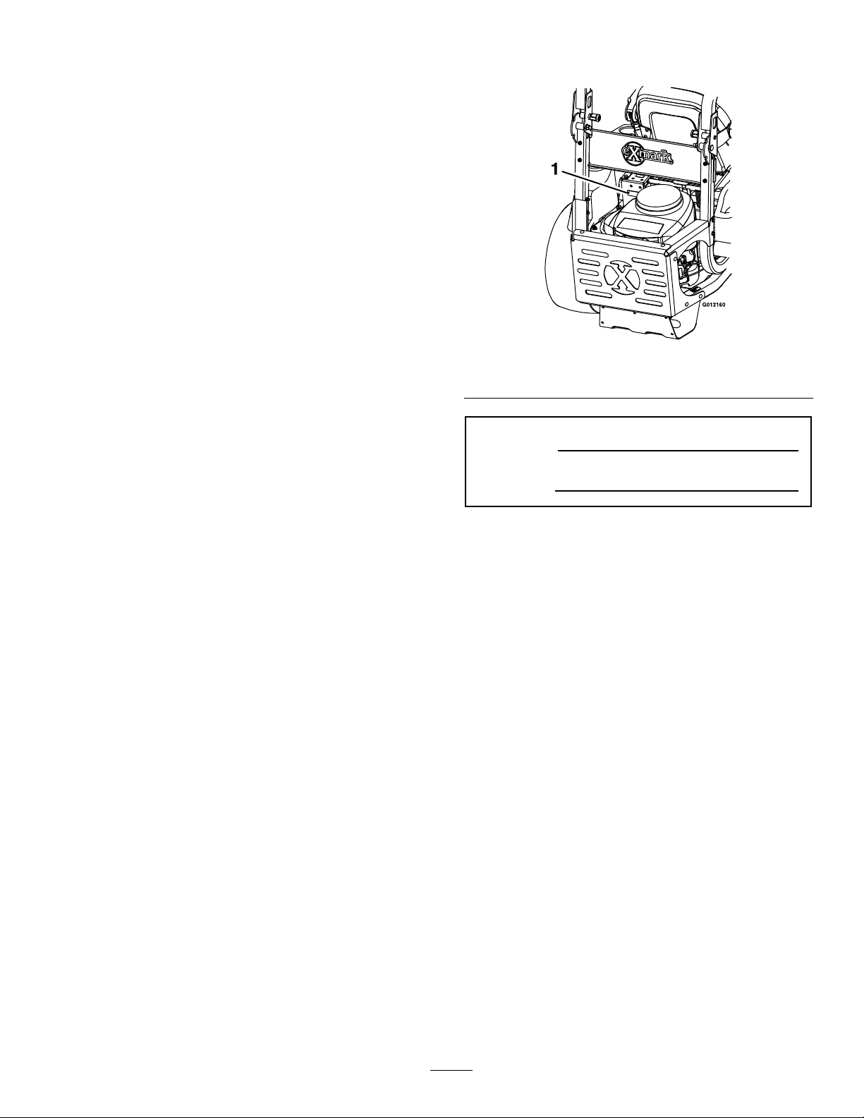
Figure1
1.Modelandserialnumberlocation
ModelNo.
SerialNo.
AllExmarkequipmentdealersanddistributorsare
keptinformedofthelatestmethodsofservicing
andareequippedtoprovidepromptandefcient
serviceintheeldorattheirservicestations.They
carryamplestockofservicepartsorcansecurethem
promptlyforyoufromthefactory.
AllExmarkpartsarethoroughlytestedandinspected
beforeleavingthefactory,however,attentionis
requiredonyourpartifyouaretoobtainthefullest
measureofsatisfactionandperformance.
Wheneveryouneedservice,genuineExmarkparts,
oradditionalinformation,contactanAuthorized
ServiceDealerorExmarkCustomerServiceandhave
themodelandserialnumbersofyourproductready.
Figure1identiesthelocationofthemodelandserial
numbersontheproduct.Writethenumbersinthe
spaceprovided.
3
Page 4

Contents
Introduction...........................................................3
Safety.....................................................................5
SafetyAlertSymbol.........................................5
SafeOperatingPractices..................................5
SafetyandInstructionalDecals.....................11
Specications.......................................................16
ModelNumbers............................................16
Systems.........................................................16
Dimensions...................................................17
TorqueRequirements....................................18
ProductOverview................................................18
Operation.............................................................19
Controls........................................................19
Pre-Start........................................................21
OperatingInstructions..................................22
Transporting.................................................26
Maintenance.........................................................28
RecommendedMaintenanceSchedule(s)...........28
PeriodicMaintenance.......................................29
CheckEngineOilLevel.................................29
CheckMowerBlades.....................................30
CheckSafetyInterlockSystem.......................31
CheckRolloverProtectionSystem(Roll
Bar)Knobs................................................32
CheckSeatBelt..............................................32
CheckforLooseHardware............................32
ServiceAirCleaner........................................32
ChangeEngineOilandFilter.........................32
CheckHydraulicOilLevel.............................32
CheckTirePressures.....................................33
CheckConditionOfBelts..............................33
LubricateGreaseFittings...............................33
CheckSparkPlugs.........................................33
ChangeFuelFilter.........................................33
ChangeHydraulicSystemFilterand
Fluid.........................................................33
CheckSparkArrester(ifequipped).................34
ThreadLockingAdhesives.............................35
Copper-BasedAnti-seize..............................35
DielectricGrease...........................................35
Adjustments.....................................................35
DeckLeveling...............................................35
AdjustingtheBladeSlope..............................36
PumpDriveBeltTension...............................37
DeckBeltTension........................................37
AdjustingtheParkingBrake...........................37
MotionControlHandleAdjustment..............38
FullForwardTrackingAdjustment.................39
AdjustingtheSeatRideSuspension................39
ElectricClutchAdjustment............................39
Cleaning...........................................................41
CleanEngineandExhaustSystem
Area..........................................................41
RemoveEngineShroudsandCleanCooling
Fins...........................................................41
CleanHydroFanCoolingFins.......................41
CleanDebrisFromMachine..........................41
CleanGrassBuild-UpUnderDeck................41
WasteDisposal..............................................42
Troubleshooting...................................................43
Schematics...........................................................45
4
Page 5
Safety
Safety
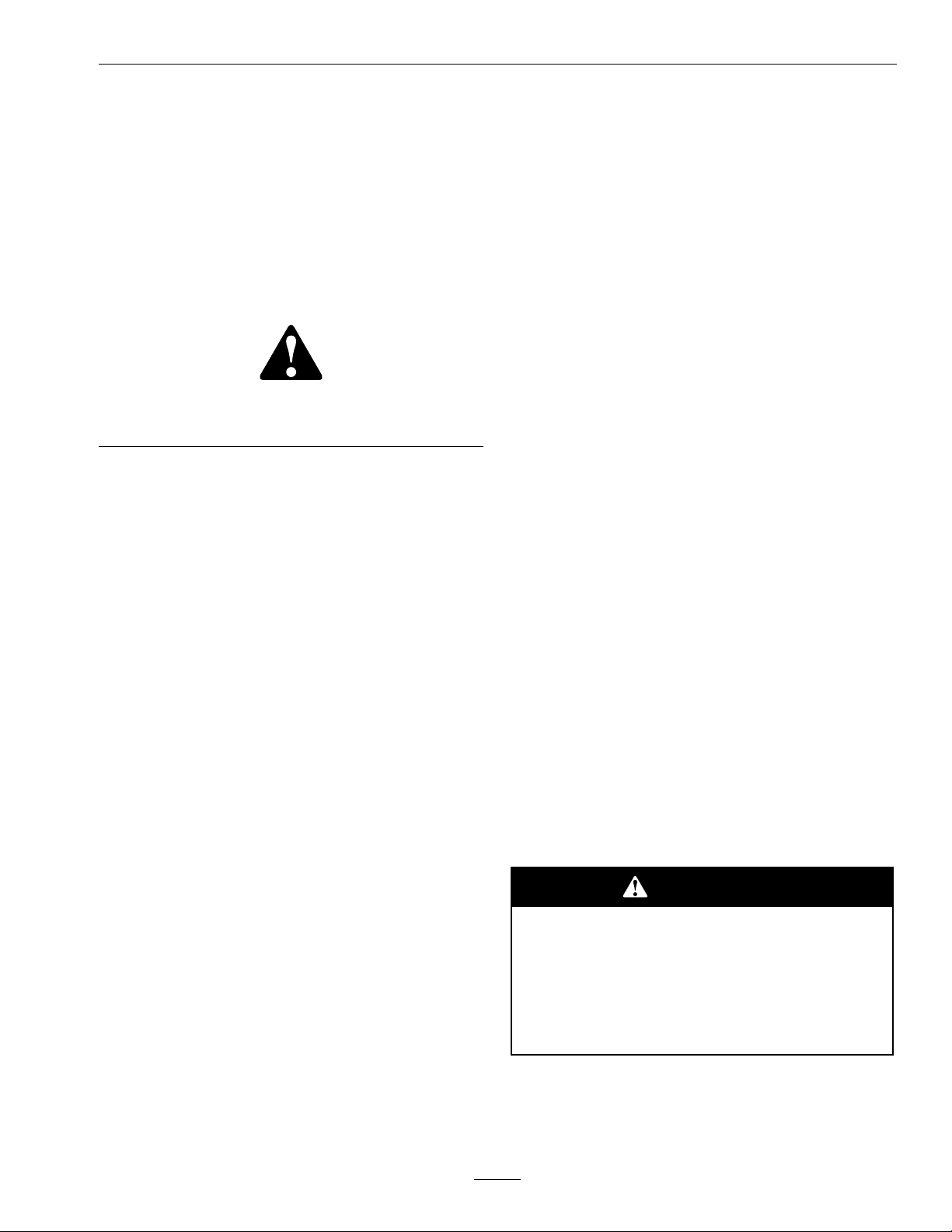
SafetyAlertSymbol
ThisSafetyAlertSymbol(Figure2)isusedbothin
thismanualandonthemachinetoidentifyimportant
safetymessageswhichmustbefollowedtoavoid
accidents.
Thissymbolmeans:ATTENTION!BECOME
ALERT!YOURSAFETYISINVOLVED!
Figure2
1.Safetyalertsymbol
Thesafetyalertsymbolappearsaboveinformation
whichalertsyoutounsafeactionsorsituations
andwillbefollowedbythewordDANGER,
WARNING,orCAUTION.
DANGER:Whitelettering/Redbackground.
Indicatesanimminentlyhazardoussituationwhich,if
notavoided,Willresultindeathorseriousinjury.
WARNING:Blacklettering/Orangebackground.
Indicatesapotentiallyhazardoussituationwhich,if
notavoided,Couldresultindeathorseriousinjury.
CAUTION:Blacklettering/Yellowbackground.
Indicatesapotentiallyhazardoussituationwhich,if
notavoided,Mayresultinminorormoderateinjury.
Thismanualusestwootherwordstohighlight
information.Importantcallsattentiontospecial
mechanicalinformationandNoteemphasizes
generalinformationworthyofspecialattention.
•Neverletchildrenoruntrainedpeopleoperate
orservicetheequipment.Localregulationsmay
restricttheageoftheoperator.
•Onlyadultsandmatureteenagersshouldoperate
amower,andevenmatureteenagersshouldhave
adultsupervision.Besureateenager:
1.hasreadandunderstandstheOperator’s
Manualandrecognizestherisksinvolved;
2.issufcientlymaturetousecaution;and
3.isofsufcientsizeandweighttooperate
thecontrolscomfortablyandtomanagethe
mowerwithouttakingrisks.
•Dataindicatesthatoperators,age60yearsand
above,areinvolvedinalargepercentageofriding
mower-relatedinjuries.Theseoperatorsshould
evaluatetheirabilitytooperatetheridingmower
safelyenoughtoprotectthemselvesandothers
fromseriousinjury.
•Theowner/usercanpreventandisresponsible
foraccidentsorinjuriesoccurringtohimselfor
herself,otherpeopleorproperty.
Preparation
•Evaluatetheterraintodeterminewhataccessories
andattachmentsareneededtoproperlyand
safelyperformthejob.Onlyuseaccessoriesand
attachmentsapprovedbyExmark.
•Wearappropriateclothingincludingsafetyglasses,
substantialfootwear,longtrousers,andhearing
protection.DoNotoperatewhenbarefootor
whenwearingopensandals.Longhair,loose
clothingorjewelrymaygettangledinmoving
parts.
SafeOperatingPractices
Training
•ReadtheOperator’sManualandothertraining
material.Iftheoperator(s)ormechanic(s)can
notreadEnglishitistheowner’sresponsibilityto
explainthismaterialtothem.
•Becomefamiliarwiththesafeoperationofthe
equipment,operatorcontrols,andsafetysigns.
•Alloperatorsandmechanicsshouldbetrained.
Theownerisresponsiblefortrainingtheusers.
CAUTION
Thismachineproducessoundlevelsin
excessof85dBAattheoperator’searand
cancausehearinglossthroughextended
periodsofexposure.
Wearhearingprotectionwhenoperatingthis
machine.
•Inspecttheareawheretheequipmentistobe
usedandremoveallrocks,toys,sticks,wires,
bones,andotherforeignobjectswhichcanbe
5
Page 6

Safety
thrownbythemachineandmaycausepersonal
injurytotheoperatororbystanders.
DANGER
Incertainconditionsgasolineisextremely
ammableandvaporsareexplosive.
Areorexplosionfromgasolinecanburn
you,others,andcausepropertydamage.
•Fillthefueltankoutdoorsonlevel
ground,inanopenarea,whentheengine
iscold.Wipeupanygasolinethatspills.
•Neverrellthefueltankordrainthe
machineindoorsorinsideanenclosed
trailer.
•DoNotllthefueltankcompletelyfull.
Fillthefueltanktothebottomoftheller
neck.Theemptyspaceinthetankallows
gasolinetoexpand.Overllingmayresult
infuelleakageordamagetotheengine
oremissionsystem(ifequipped).
•Neversmokewhenhandlinggasoline,
andstayawayfromanopenameor
wheregasolinefumesmaybeignitedby
spark.
•Storegasolineinanapprovedcontainer
andkeepitoutofthereachofchildren.
DANGER
Incertainconditionsduringfueling,static
electricitycanbereleasedcausingaspark
whichcanignitegasolinevapors.Areor
explosionfromgasolinecanburnyouand
othersandcausepropertydamage.
•Alwaysplacegasolinecontainersonthe
groundawayfromyourvehiclebefore
lling.
•DoNotllgasolinecontainersinsidea
vehicleoronatruckortrailerbedbecause
interiorcarpetsorplastictruckbedliners
mayinsulatethecontainerandslowthe
lossofanystaticcharge.
•Whenpractical,removegas-powered
equipmentfromthetruckortrailerand
refueltheequipmentwithitswheelson
theground.
•Ifthisisnotpossible,thenrefuelsuch
equipmentonatruckortrailerfroma
portablecontainer,ratherthanfroma
gasolinedispensernozzle.
•Ifagasolinedispensernozzlemustbe
used,keepthenozzleincontactwiththe
rimofthefueltankorcontaineropening
atalltimesuntilfuelingiscomplete.
•Addfuelbeforestartingtheengine.
Neverremovethecapofthefueltankor
addfuelwhenengineisrunningorwhen
theengineishot.
•Iffuelisspilled,DoNotattempttostart
theengine.Moveawayfromtheareaof
thespillandavoidcreatinganysourceof
ignitionuntilfuelvaporshavedissipated.
•DoNotoperatewithoutentireexhaust
systeminplaceandinproperworking
condition.
WARNING
Gasolineisharmfulorfatalifswallowed.
Long-termexposuretovaporshascaused
cancerinlaboratoryanimals.Failuretouse
cautionmaycauseseriousinjuryorillness.
•Avoidprolongedbreathingofvapors.
•Keepfaceawayfromnozzleandgas
tank/containeropening.
•Keepawayfromeyesandskin.
•Neversiphonbymouth.
•Iffuelisspilledonclothing,changeclothing
immediately.
•Checkthattheoperator’spresencecontrols,
safetyswitches,andshieldsareattachedand
6
Page 7

Safety
functioningproperly .DoNotoperateunlessthey
arefunctioningproperly .
Operation
WARNING
Operatingengineparts,especiallythe
mufer,becomeextremelyhot.Severeburns
canoccuroncontactanddebris,suchas
leaves,grass,brush,etc.cancatchre.
•Allowengineparts,especiallythemufer,
tocoolbeforetouching.
•Removeaccumulateddebrisfrommufer
andenginearea.
•Installandmaintaininworkingordera
sparkarresterbeforeusingequipment
onforest-covered,grass-covered,or
brush-coveredunimprovedland.
WARNING
Engineexhaustcontainscarbonmonoxide,
whichisanodorlessdeadlypoisonthatcan
killyou.
–Beforechecking,cleaningorworkingonthe
mower.
–Afterstrikingaforeignobjectorabnormal
vibrationoccurs(inspectthemowerfor
damageandmakerepairsbeforerestarting
andoperatingthemower).
–Beforeclearingblockages.
–Wheneveryouleavethemower.
•Stopengine,waitforallmovingpartstostop,and
engageparkingbrake:
–Beforerefueling.
–Beforedumpingthegrasscatcher.
WARNING
Hands,feet,hair,clothing,oraccessoriescan
becomeentangledinrotatingparts.Contact
withtherotatingpartscancausetraumatic
amputationorseverelacerations.
•DoNotoperatethemachinewithout
guards,shields,andsafetydevicesin
placeandworkingproperly.
•Keephands,feet,hair,jewelry ,orclothing
awayfromrotatingparts.
DoNotrunengineindoorsorinasmall
connedareawheredangerouscarbon
monoxidefumescancollect.
•Operateonlyindaylightorgoodarticiallight,
keepingawayfromholesandhiddenhazards.
•Besurealldrivesareinneutralandparkingbrake
isengagedbeforestartingengine.Useseatbelts
withtherollbarintheraisedandlockedposition.
•Neveroperatethemowerwithdamagedguards,
shields,orcovers.Alwayshavesafetyshields,
guards,switchesandotherdevicesinplaceandin
properworkingcondition.
•Nevermowwiththedischargedeectorraised,
removedoralteredunlessthereisagrass
collectionsystemormulchkitinplaceand
workingproperly .
•DoNotchangetheenginegovernorsettingor
overspeedtheengine.
•Stopengine,waitforallmovingpartstostop,
removekeyandengageparkingbrake:
•NEVERcarrypassengers.DONOToperate
themowerwhenpeople,especiallychildren,or
petsareinthearea.
•Bealert,slowdownandusecautionwhenmaking
turns.Lookbehindandtothesidebefore
changingdirections.DoNotmowinreverse
unlessabsolutelynecessary.
•Stoptheblades,slowdown,andusecautionwhen
crossingsurfacesotherthangrassandwhen
transportingthemowertoandfromtheareato
bemowed.
•Beawareofthemowerdischargepathanddirect
dischargeawayfromothers.
•DoNotoperatethemowerundertheinuence
ofalcoholordrugs.
•Useextremecarewhenloadingorunloadingthe
machineintoatrailerortruck.
•Usecarewhenapproachingblindcorners,shrubs,
trees,orotherobjectsthatmayobscurevision.
•Watchfortrafcwhenoperatingnearorcrossing
roadways.
7
Page 8
Safety
SlopeOperation
UseExtremecautionwhenmowingand/orturning
onslopesaslossoftractionand/ortip-overcould
occur.Theoperatorisresponsibleforsafeoperation
onslopes.
DANGER
Operatingonwetgrassorsteepslopescan
causeslidingandlossofcontrol.Wheels
droppingoveredges,ditches,steepbanks,or
watercancauserollovers,whichmayresult
inseriousinjury,deathordrowning.
•DoNotmowslopeswhengrassiswet.
•DoNotmowneardrop-offsornearwater.
•DoNotmowslopesgreaterthan15
degrees.
•Reducespeedanduseextremecaution
onslopes.
•Avoidsuddenturnsorrapidspeed
changes.
•Keeptherollbarintheraisedandlocked
positionanduseseatbelt.
•Seeinsidethebackcovertodeterminethe
approximateslopeangleoftheareatobemowed.
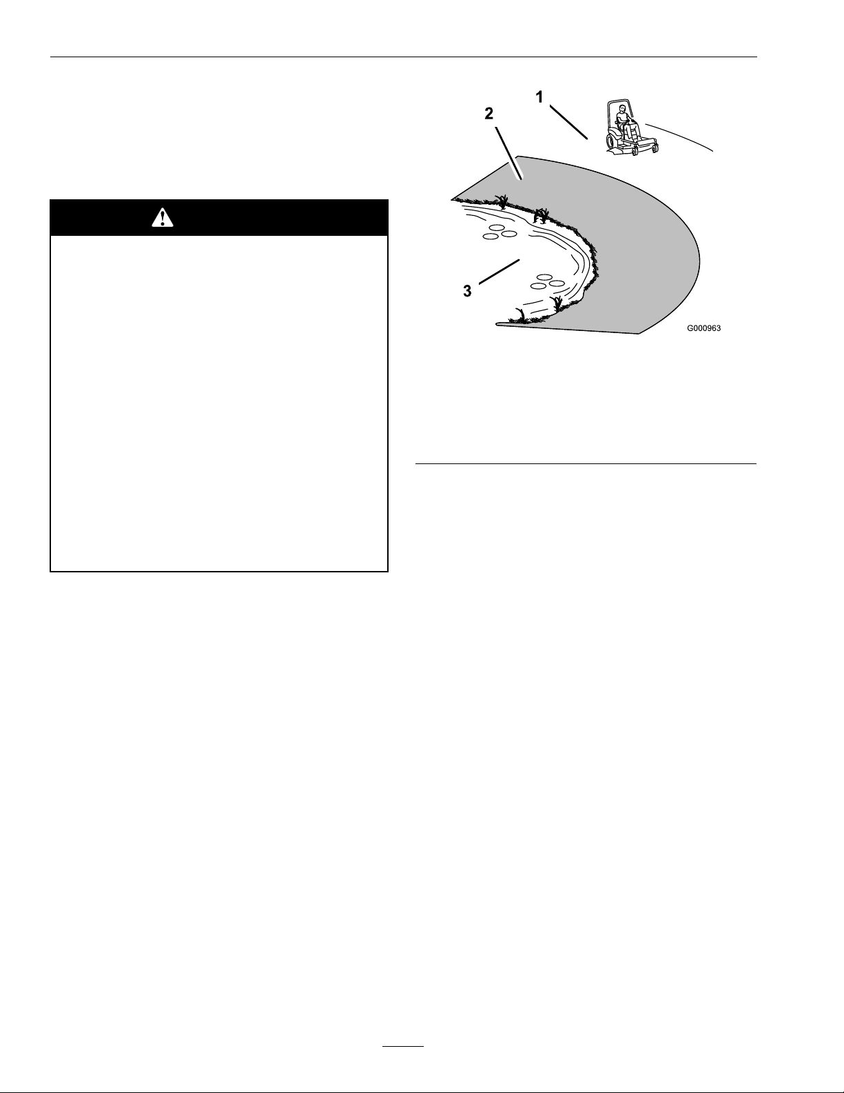
•Useawalkbehindmowerand/orahandtrimmer
neardrop-offs,ditches,steepbanksorwater.
(Figure3).
Figure3
1.SafeZone-Usethemowerhereonslopeslessthan15
degrees
2.DangerZone-Useawalkbehindmowerand/orhand
trimmeronslopesgreaterthan15degrees,near
drop-offsandwater.
3.Water
•Removeormarkobstaclessuchasrocks,tree
limbs,etc.fromthemowingarea.Tallgrasscan
hideobstacles.
•Watchforditches,holes,rocks,dipsandrisesthat
changetheoperatingangle,asroughterraincould
overturnthemachine.
•Avoidsuddenstartswhenmowinguphillbecause
themowermaytipbackwards.
•Beawarethatoperatingonwetgrass,acrosssteep
slopesordownhillmaycausethemowertolose
traction.Lossoftractiontothedrivewheelsmay
resultinslidingandlossofbrakingandsteering.
•Alwaysavoidsuddenstartingorstoppingona
slope.Iftireslosetraction,disengagetheblades
andproceedslowlyofftheslope.
•Followthemanufacturer’ srecommendationsfor
wheelweightsorcounterweightstoimprove
stability.
•Useextremecarewithgrasscatchersor
attachments.Thesecanchangethestabilityofthe
machineandcauselossofcontrol.
UsingtheRolloverProtectionSystem
(ROPS)
ARolloverProtectionSystem(rollbar)isinstalled
ontheunit.
8
Page 9

Safety
WARNING
Thereisnorolloverprotectionwhentheroll
barisdown.Wheelsdroppingoveredges,
ditches,steepbanks,orwatercancause
rollovers,whichmayresultinseriousinjury,
deathordrowning.
•Keeptherollbarintheraisedandlocked
positionanduseseatbelt.
•Lowertherollbaronlywhenabsolutely
necessary.
•DoNotwearseatbeltwhentherollbar
isdown.
•Driveslowlyandcarefully.
•Raisetherollbarassoonasclearance
permits.
•Checkcarefullyforoverheadclearances(i.e.
branches,doorways,andelectricalwires)before
drivingunderanyobjectsandDoNotcontact
them.
•Intheeventofarollover,taketheunittoan
AuthorizedServiceDealertohavetheROPS
inspected.
Children
•Keepchildrenoutofthemowingareaandunder
thewatchfulcareofanotherresponsibleadult,
nottheoperator.
•Bealertandturnthemachineoffifchildrenenter
thearea.
•Beforeandwhilebackingorchangingdirection,
lookbehind,down,andside-to-sideforsmall
children.
•Nevercarrychildren,evenwiththebladesoff.
Theymayfalloffandbeseriouslyinjuredor
interferewithsafemachineoperation.
•Childrenwhohavebeengivenridesinthepast
maysuddenlyappearinthemowingareafor
anotherrideandberunoverorbackedoverby
themower.
•Neverallowchildrentooperatethemachine.
Towing
•UsefortowingonlyifequippedwithanExmark
hitchkit.DoNotattachtowedequipmentexcept
atthehitchpoint.
•FollowExmark’srecommendationforweight
limitsfortowedequipmentandtowingonslopes.
Thisinformationcanbefoundinthehitchkit
instructionsheetandonthedecal.
•Neverallowchildrenorothersinorontowed
equipment.
•Onslopes,theweightofthetowedequipment
maycauselossoftractionandlossofcontrol.
•Travelslowlyandallowextradistancetostop.
MaintenanceandStorage
•Disengagedrives,lowerimplement,setparking
brake,stopengineandremovekeyordisconnect
sparkplugwire.Waitforallmovementtostop
beforeadjusting,cleaningorrepairing.
•Keepengineandengineareafreefrom
accumulationofgrass,leaves,excessivegrease
oroil,andotherdebriswhichcanaccumulate
intheseareas.Thesematerialscanbecome
combustibleandmayresultinare.
•LetenginecoolbeforestoringandDoNotstore
nearameoranyenclosedareawhereopenpilot
lightsorheatappliancesarepresent.
•Shutofffuelwhilestoringortransporting.Do
Notstorefuelnearamesordrainindoors.
•Parkmachineonlevelground.Neverallow
untrainedpersonneltoservicemachine.
•Usejackstandstosupportcomponentswhen
required.
•Carefullyreleasepressurefromcomponentswith
storedenergy.
•Disconnectbatteryorremovesparkplugwire
beforemakinganyrepairs.Disconnectthe
negativeterminalrstandthepositivelast.
Reconnectpositiverstandnegativelast.
•Usecarewhencheckingblades.Wraptheblade(s)
orweargloves,andusecautionwhenservicing
them.Onlyreplacedamagedblades.Never
straightenorweldthem.
•Keephandsandfeetawayfrommovingparts.
Ifpossible,DoNotmakeadjustmentswiththe
enginerunning.
9
Page 10

Safety
•Checkforproperbrakeoperationfrequently .
Adjustandserviceasrequired.
•Chargebatteriesinanopenwellventilatedarea,
awayfromsparkandames.Unplugcharger
beforeconnectingordisconnectingfrombattery.
Wearprotectiveclothinganduseinsulatedtools.
DANGER
Chargingthebatterymayproduceexplosive
gasses.Batterygassescanexplodecausing
seriousinjury.
•Keepsparks,ames,orcigarettesaway
frombattery.
•Ventilatewhenchargingorusingbattery
inanenclosedspace.
•Makesureventingpathofbatteryis
alwaysopenoncebatteryislledwith
acid.
WARNING
Removingstandardoriginalequipment
parts,orusingnon-Exmarkreplacement
partsandaccessoriesmayalterthewarranty,
traction,andsafetyofthemachine.Failure
touseoriginalExmarkpartscouldcause
seriousinjuryordeath.
Replaceallpartsincluding,butnotlimited
to,tires,belts,andbladeswithoriginal
Exmarkparts.
CAUTION
Iftheignitionisinthe“ON”positionthere
ispotentialforsparksandengagement
ofcomponents.Sparkscouldcausean
explosionormovingpartscouldaccidentally
engagecausingpersonalinjury
Besureignitionswitchisinthe“OFF”
positionbeforechargingthebattery.
•Keepallguards,shieldsandallsafetydevicesin
placeandinsafeworkingcondition.
•Checkallboltsfrequentlytomaintainproper
tightness.
•Frequentlycheckforwornordeteriorating
componentsthatcouldcreateahazard.
10
Page 11
SafetyandInstructionalDecals
Safety
•Keepallsafetysignslegible.Removeallgrease,
dirtanddebrisfromsafetysignsandinstructional
labels.
•Replaceallworn,damaged,ormissingsafety
signs.
•Whenreplacementcomponentsareinstalled,be
surethatcurrentsafetysignsareafxedtothe
replacedcomponents.
•Ifanattachmentoraccessoryhasbeeninstalled,
makesurecurrentsafetysignsarevisible.
1-303508
•Newsafetysignsmaybeobtainedfrom
yourauthorizedExmarkequipmentdealeror
distributororfromExmarkMfg.Co.Inc.
•Safetysignsmaybeafxedbypeelingoffthe
backingtoexposetheadhesivesurface.Apply
onlytoaclean,drysurface.Smoothtoremove
anyairbubbles.
•Familiarizeyourselfwiththefollowingsafetysigns
andinstructionlabels.Theyarecriticaltothesafe
operationofyourExmarkcommercialmower.
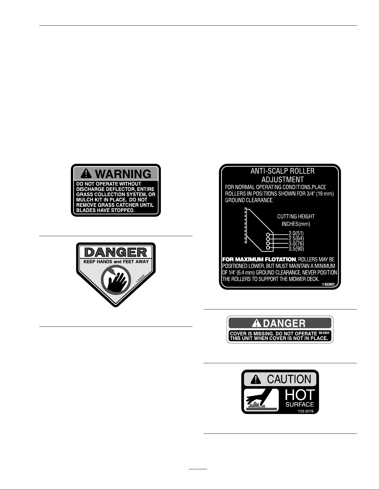
1-633922
1-403005
98-5954
103-2076
11
Page 12
Safety
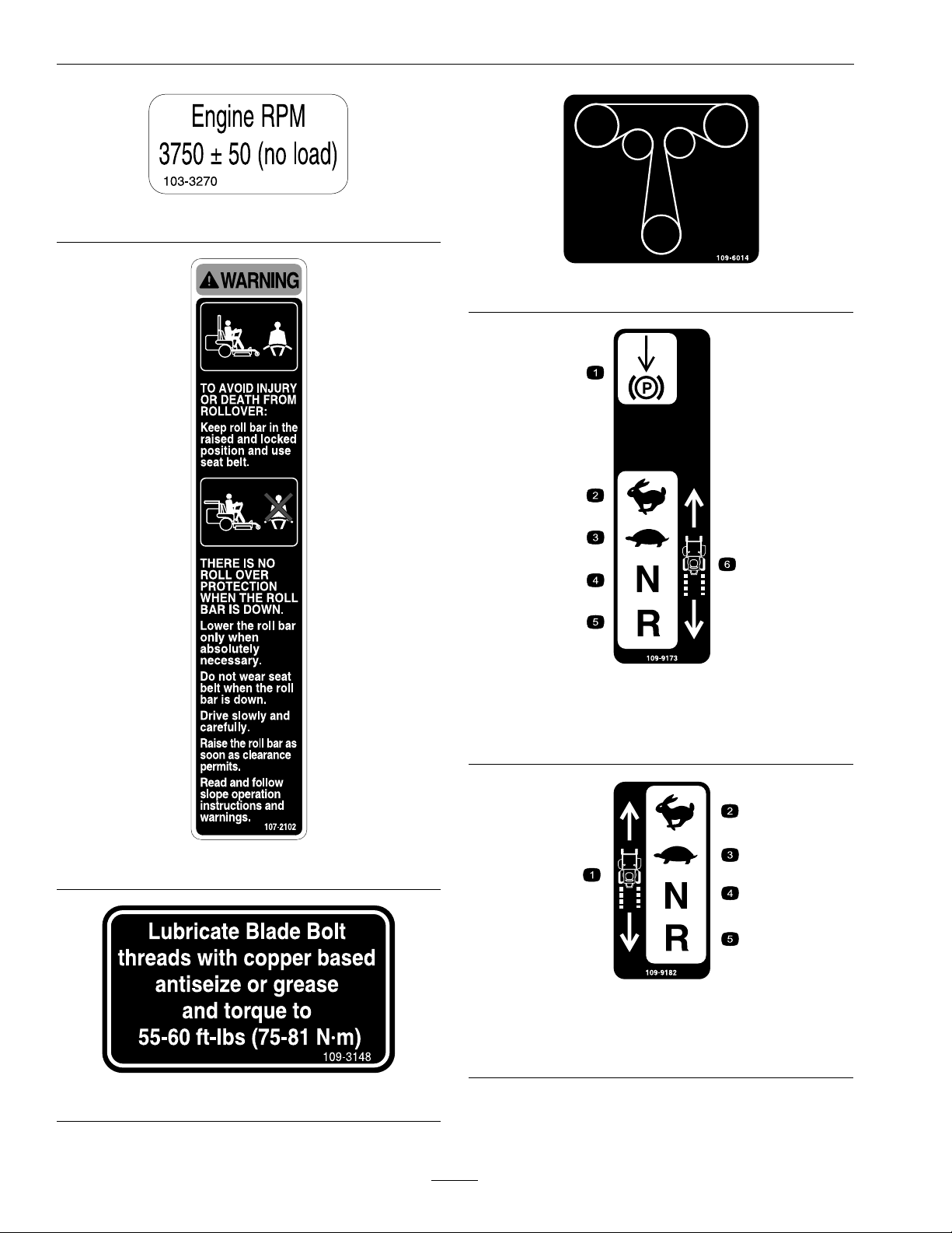
103-3270
109-6014
109-9173
1.Parkingbrake4.Neutral
2.Fast5.Reverse
3.Slow
6.Machinespeed
107-2102
109-9182
1.Machinespeed4.Neutral
2.Fast5.Reverse
3.Slow
109-3148
12
Page 13
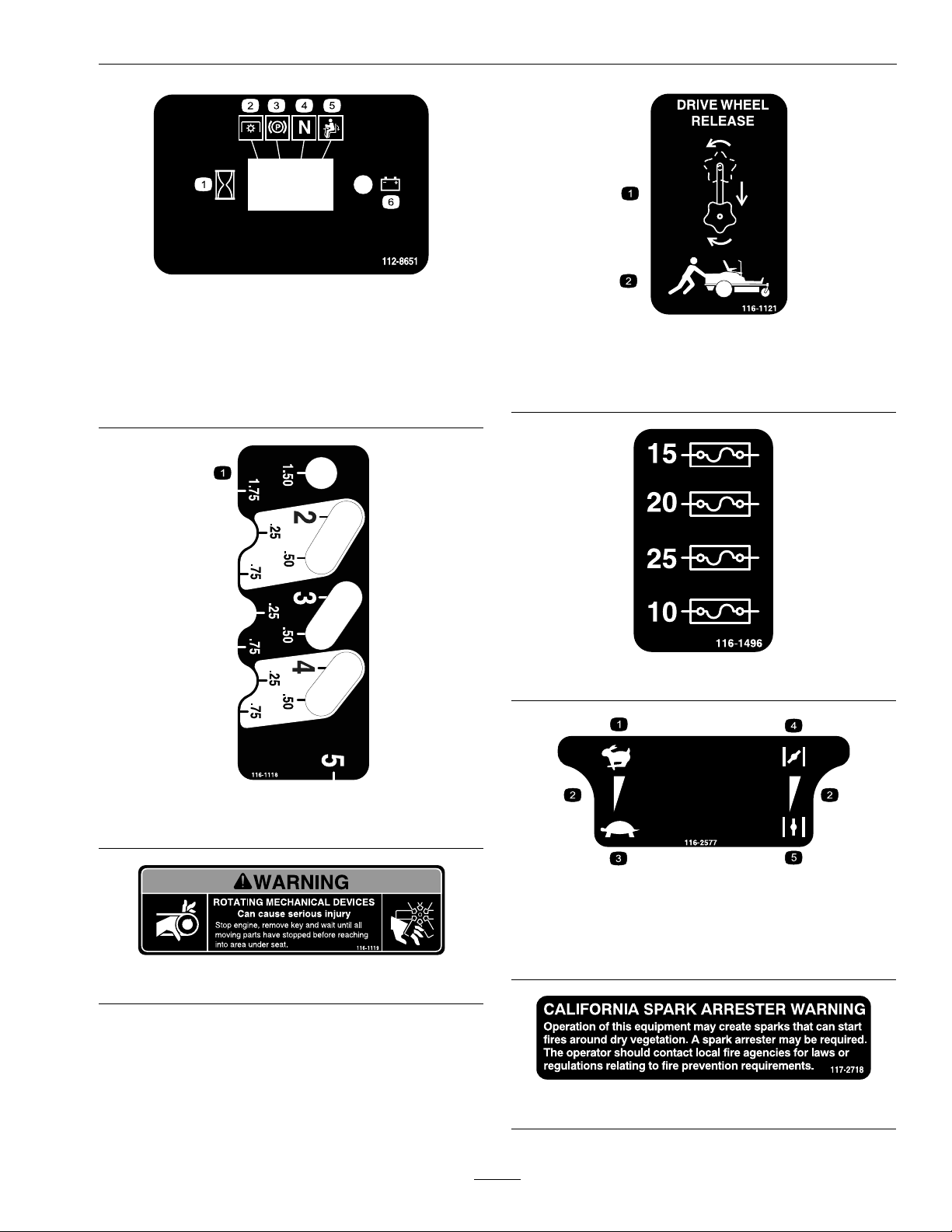
1.Interval
2.PowerT ake-off(PTO)
3.Parkingbrake
4.Neutral
5.Operatorpresenceswitch
6.Battery
Safety
112-8651
116-1121
1.Rotatethedriverelease
knobtoloosen,slidethe
knob,andtighten
2.Pushthemachine
1.Heightofcut
116-1118
116-1119
1.Fast
2.Continuousvariable
setting
3.Slow
116-1496
116-2577
4.Choke-on
5.Choke-off
117-2718
13
Page 14
Safety
PTOSwitchSymbols
1.PTO–disengage2.PTO–engage
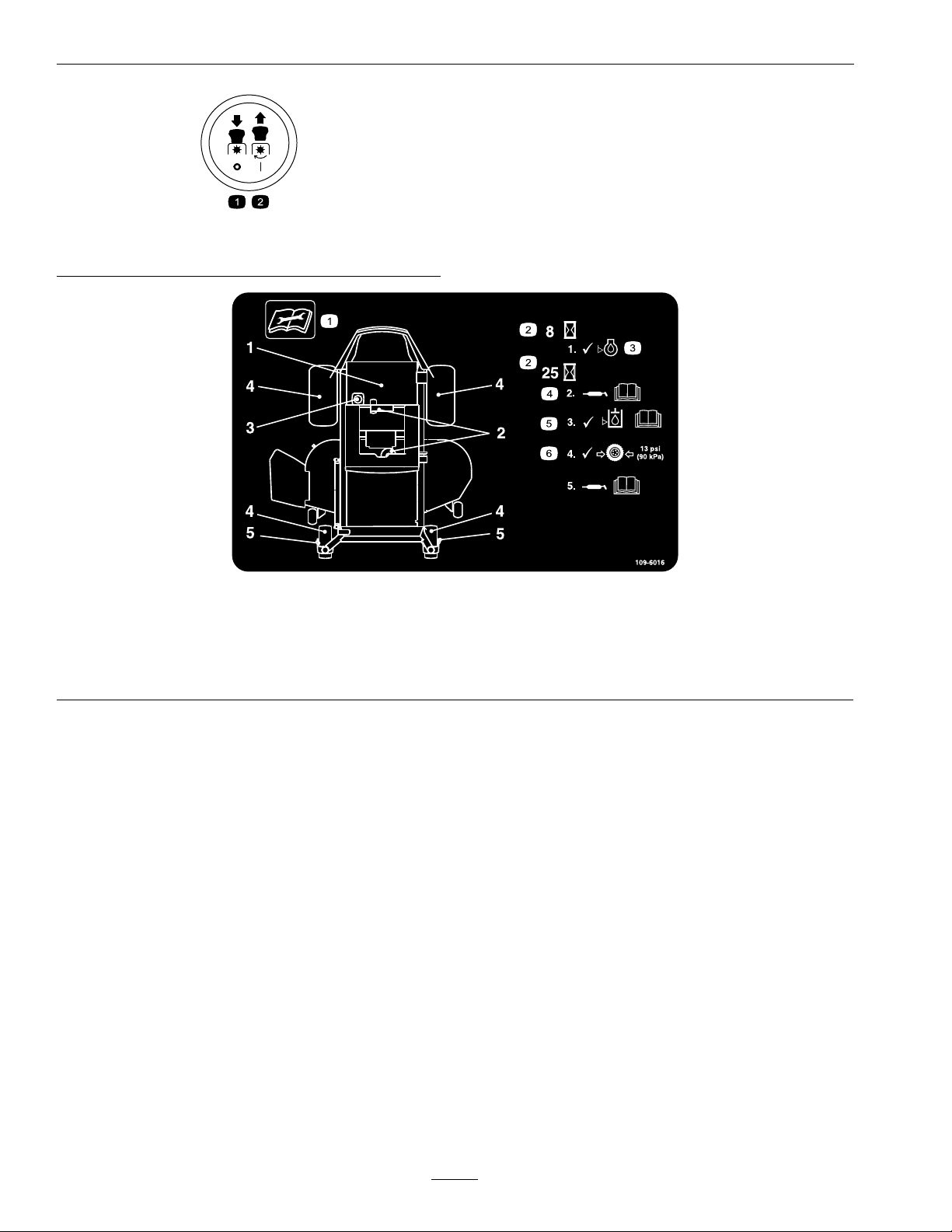
109-6016
1.Readtheinstructionsbeforeservicingorperforming
maintenance
2.Timeinterval
3.Checkoillevel6.Checktirepressure
4.RefertotheOperator’smanualforgreaseinstructions
5.CheckhydraulicoillevelandrefertotheOperator’s
manualforfurtherinstructions
14
Page 15
Safety
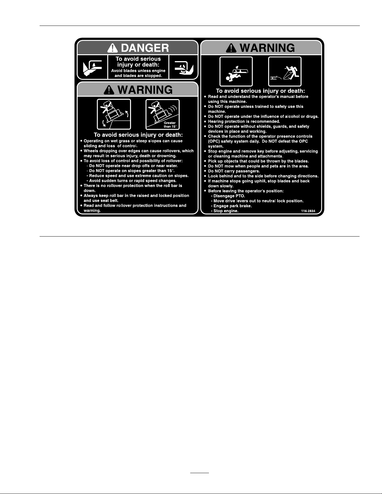
116-2834
15
Page 16

Specications
Specications
ModelNumbers
SerialNos:850,000andHigher
QSP20BV443;QSP20KAS443;QSP20KAS483;QSP20KAX443;QSP22KAS523
Systems
Engine
•EngineSpecications:SeeyourEngineOwner’s
Manual
•RPM:
–20HPBriggs&Stratton
FullSpeed:3750±50(max)RPM(PTOnot
engaged)Idle:1650(min)RPM
–20HP&22HPKawasaki
FullSpeed:3750±50(max)RPM(PTOnot
engaged)Idle:1550(min)RPM
FuelSystem
•Capacity:4.0gal.(15.1L)
•TypeofFuel:Regularunleadedgasoline,87
octaneorhigher;containingnomorethan10%
methanolorethanol.
•FuelFilter:
Briggs&StrattonP/N691035
KawasakiP/N49019-7005
•FuelShut-OffValve:1/4turnincrements(“ON”,
“OFF”)
ElectricalSystem
•ChargingSystem:FlywheelAlternator
•ChargingCapacity:16amps
•BatteryType:BCIGroupU1
•BatteryVoltage:12Volt
•Polarity:NegativeGround
SafetyInterlockSystem
•LCDindicatorsappearforthePTO,parkbrake,
drivelevers,andoperatorpresenceinthemessage
displayontheRHcontrolpanel.
•PTOmustbedisengaged,brakeengaged,and
motioncontrolleversout(neutrallock)tostart
engine.(Itisnotnecessaryfortheoperatortobe
intheseattostarttheengine.)
•OperatormustbeinseatwhenPTOisengaged,
brakeisdisengaged,ormotioncontrolleversare
movedinorenginewillstop.
•Enginewillstopifeithertheleft,theright,or
bothleversaremovedfromneutrallockposition
whilebrakeisengaged.
OperatorControls
•SteeringandMotionControl:
Note:Motioncontrolleversareadjustableto
threeheights.
–Separatelevers,oneachsideoftheconsole,
controlspeedanddirectionoftravelofthe
respectivedrivewheels.
–Steeringiscontrolledbyvaryingtheposition
oftheleversrelativetoeachother.
–Movingmotioncontrolleversoutward(in
slots)locksthedrivesysteminneutral.
•PTOEngagementSwitch:Engageselectricclutch
(todrivebelt)whichengagesmowerblades.
•ParkingBrakeLever:Engagesparkingbrake.
•DeckHeightAdjustmentPin:Setscuttingheight
todesiredposition.
•DeckLiftLever:Footpedalthatraisesthedeck.
•TransportLock:Automaticallylatchesatthe
transportposition.
•Fuses:One25amp,one20amp;one15amp;
one10ampbladetype
•Diode:TVS
Seat
•Type:Standardseatwithhighback,foampadded
withspringsuspensionandarmrests.
16
Page 17

Specications
•Mounting:Hingedtotiltupforaccessto
hydraulicpumps,batteryandothercomponents.
Heldintiltedpositionwithlanyard.Adjustable
foreandaft.
•Armrests:Standard–foampaddedip-up
adjustableheightarmrests.
•SeatSafetySwitch:IncorporatedintotheSafety
InterlockSystem.
HydrostaticGroundDriveSystem
•HydrostaticPumps:TwoHydroGearZT–3100
Integrateddrivesystems.
•HydraulicOilType:ExmarkPremiumHydrooil.
•Speeds:
–0-8mph(13km/hr)forward.
–0-5mph(8km/hr)reverse.
•Drivewheelreleases,locatedonleftandright
sidesofenginedeck,allowmachinetobemoved
whentheengineisnotrunningandbrakeisoff.
Tires&Wheels
Drive
Pneumatic(Air-Filled)
DeckSize
Quantity
Tread
Size20x7.00-1020x10.00-1013x5.00–6
PlyRating
Pressure
44&4852
222
TurfMasterTurfMasterSmooth
44
13psi
(90kPa)
13psi
(90kPa)
Front
Caster
Pneumatic
(Air-Filled)
All
13psi
(90kPa)
–52inchDeck:18.00inches(45.7cm)–(3ea.)
•BladeSpindles:Solidsteelspindleswithno
maintenancebearings.
•DeckDrive:Electricclutchmountedonvertical
engineshaft.Bladesaredrivenbyonebelt
(w/self-tensioningidler)directfromtheengine.
•Deck:Fulloatingdeckisattachedtoout-front
supportframe.Maximumturfprotectionis
providedwithanti-scalprollers.
Deckdesignallowsforbagging,mulchingorside
discharge.
•DeckDepth:
–44inchDeck:5.0inches(12.7cm)
–48inchDeck:5.0inches(12.7cm)
–52inchDeck:5.0inches(12.7cm)
•CuttingHeightAdjustment:Afootdeckliftlever
isusedtoadjustthecuttingheightfrom11/2
inch(3.8cm)to5inches(12.7cm)in1/4inch
(6.4mm)increments.
•MulchingKit:Optional.
Dimensions
OverallWidth:
Without
Deck
Deector
Up
Deector
Down
44inch
Deck
44.0inches
(112cm)
48.5inches
(123cm)
56.7inches
(144cm)
48inch
Deck
44.0inches
(112cm)
51.9inches
(132cm)
59.9inches
(152cm)
52inch
Deck
46.5inches
(118cm)
56.0inches
(142cm)
64.6inches
(164cm)
CuttingDeck
•CuttingWidth:
–44inchDeck:44inches(112cm)
–48inchDeck:48inches(122cm)
–52inchDeck:52inches(132cm)
•Discharge:Side
•BladeSize:
–44inchDeck:22.25inches(56.5cm)–(2ea.)
–48inchDeck:16.25inches(41.3cm)–(3ea.)
OverallLength:
44inchDeck48inchDeck52inchDeck
78.7inches
(200cm)
77.7inches
(197cm)
OverallHeight:
RollBar-UpRollBar-Down
76.0inches(193cm)45.5inches(116cm)
17
77.7inches
(197cm)
Page 18
ProductOverview
TreadWidth:(CentertoCenterof
Tires,Widthwise)
Drive
Wheels
Caster
Wheels
44inch
Deck
36.0inches
(91cm)
26.7inches
(68cm)
48inch
Deck
36.0inches
(91cm)
33.5inches
(85cm)
52inch
Deck
37.2inches
(96cm)
33.5inches
(85cm)
WheelBase:(CenterofCasterTireto
CenterofDriveTire)
44inch48&52inch
49.6inches(126cm)48.9inches(124cm)
CurbWeight:
44inchDeck48inchDeck52inchDeck
805lb(365kg)835lb(379kg)845lb(383kg)
ProductOverview
TorqueRequirements
BoltLocation
SpindlePulleyNut130-160ft-lb(176-217
BladeMountingBolt
(lubricatewithanti-seize)
EngineMountingBolts
InTappedBosses
EngineThroughMounting
Bolts
Anti-ScalpRollerNyloc
Nut
WheelLugNuts
ClutchMountingBolt
(securedwiththreadlocker)
DeckLiftFlangeBearing
Bolts
RolloverProtectionSystem
(RollBar)FrameMounting
Nuts
Torque
N-m)
50-60ft-lb(68-81N-m)
27-33ft-lb(37-45N-m)
15-19ft-lb(20-25N-m)
27-33ft-lb(37-45N-m)
70-90ft-lb(95-122N-m)
50-60ft-lb(68-81N-m)
40-60in-lb(4.5-7.0N-m)
67-83ft-lb(91-112N-m)
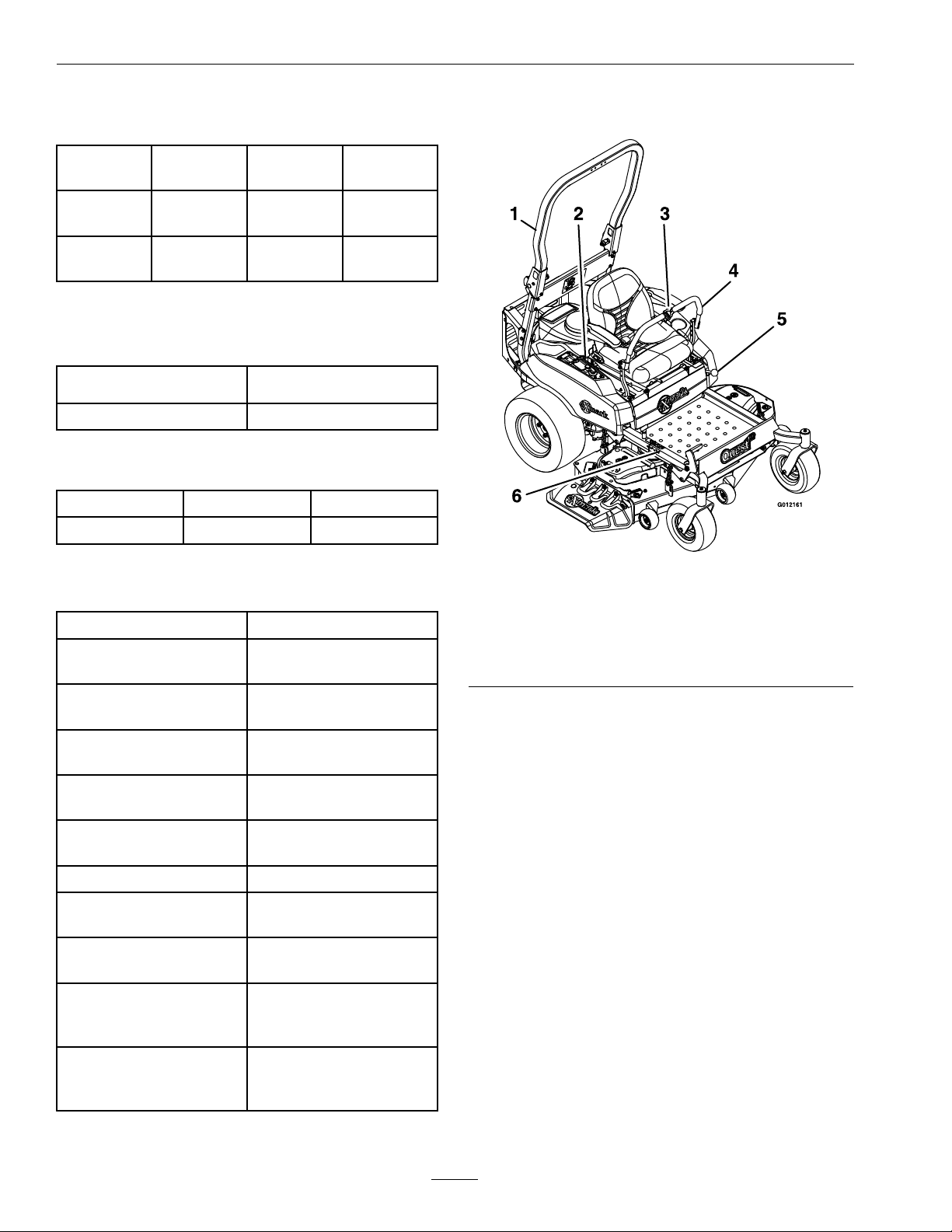
Figure4
1.RolloverProtection
System(ROPS)
2.EngineControls(right
console)
3.Seatbelt6.Heightofcutadjustment
4.Motioncontrollevers
5.Parkingbrake
RolloverProtectionSystem
(RollBar)Anti-Rack
MountingBolts
175-225in-lb(20-25N-m)
18
Page 19

Operation
Operation
Note:Determinetheleftandrightsidesofthe
machinefromthenormaloperatingposition.
Controls
MotionControlLevers
Themotioncontrolleverslocatedoneachsideof
theconsolecontroltheforwardandreversemotion
ofthemachine.
Movingtheleversforwardorbackwardturns
thewheelonthesamesideforwardorreverse
respectively.Wheelspeedisproportionaltothe
amounttheleverismoved.
Movingtheleversoutwardfromthecenterposition
intotheT-slotlocksthemintheneutralposition
(Figure5).
position.DoNotrunawarmenginewithchokein
the“ON”position.
Figure6
1.Throttlelever4.Bladecontrolswitch
2.Chokelever
3.Hourmeter
(powertake-off)
5.Ignitionswitch
Figure5
1.Neutrallockposition
(handlesout)
2.Neutraloperateposition
(handlesin)
3.FrontofUnit
4.Forward
5.Neutral(operate)
6.Reverse
ChokeControl
Locatedonrightconsole(blacklever)(seeFigure6).
ThrottleControl
Locatedonrightconsole(redlever)(seeFigure6).
Thethrottleisusedtocontrolenginespeed.Moving
thethrottleleverforwardwillincreaseenginespeed
andmovingthethrottlelevertotherearwilldecrease
enginespeed.Movingthethrottleforwardintothe
detentisfullthrottle.
BrakeLever
Locatedonleftsideofunit,justtothefrontofthe
LHmotioncontrollever.
Thebrakeleverengagesaparkingbrakeonthedrive
wheels.
Pulltheleverupandrearwardtoengagethebrake.
Pushtheleverforwardanddowntodisengagethe
brake.
Theunitmustbetieddownandbrakeengagedwhen
transporting.
Thechokeisusedtoaidinstartingacoldengine.
Movingthechokeleverforwardwillputthechokein
the“ON”positionandmovingthechokelevertothe
rear,tothedetent,willputthechokeinthe“OFF”
IgnitionSwitch
Locatedonrightconsole(seeFigure6).
19
Page 20

Operation
Theignitionswitchisusedtostartandstopthe
engine.Theswitchhasthreepositions“OFF”,“ON”
and“START”.Insertkeyintoswitchandrotate
clockwisetothe“ON”position.Rotateclockwiseto
thenextpositiontoengagethestarter(keymustbe
heldagainstspringpressureinthisposition).Allow
thekeytoreturntothe“on”positionimmediately
aftertheenginestarts.
Figure7
1.Off3.Start
2.On
Note:Brakemustbeengaged,motioncontrol
leversout(neutrallockposition)andPTOswitch
disengagedtostartengine.(Itisnotnecessaryforthe
operatortobeintheseattostarttheengine.)
Thefuelshut-offvalveisusedtoshutoffthefuel
whenthemachinewillnotbeusedforafewdays,
duringtransporttoandfromthejobsite,andwhen
parkedinsideabuilding.
Alignvalvehandlewiththefuellinetoopen.Rotate
90°toclose.
DriveWheelReleaseValves
WARNING
Handsmaybecomeentangledintherotating
drivecomponentsbelowtheenginedeck,
whichcouldresultinseriousinjuryordeath.
Stopengine,removekey,allowallthemoving
partstostopbeforeaccessingthedrivewheel
releasevalves.
WARNING
Theengineandhydraulicdriveunitscan
becomeveryhot.Touchingahotengineor
hydraulicdriveunitscancausesevereburns.
HourMeter
Locatedonthecontrolpanel(seeFigure6and
Figure8).
Thehourmeterrecordsthenumberofhoursthat
theenginehasrun.
Figure8
1.LCDindicators3.Hour/Voltagedisplay
2.Lowvoltageindicator
light
Allowtheengineandhydraulicdriveunitsto
coolcompletelybeforeaccessingthedrive
wheelreleasevalves.
Locatedoneithersideoftheenginedeck.
Duringnormaloperatingconditions,thedrivewheel
releasevalvesarepositionedhorizontally .Ifthe
machinehastobepushedbyhand,thevalvesmust
beinthe“released”position(seeFigure9).
FuelShut-OffValve
Locatedbehindandbelowtheseat.
20
Page 21

Figure9
1.Frontofthemachine
2.Rotatebypassreleaseknobcounterclockwisetoloosen
3.Leverpositionforoperatingthemachine
4.Pullleverinthisdirectiontopushthemachine
5.Leverpositionforpushingthemachine
6.Rotatebypassreleaseknobclockwisetotighten
7.Releaselever
Toreleasethedrivesystem(seeitem1inFigure9),
loosentheknobbyturningcounterclockwise.Then
pullthereleaseleverontheundersideofmachine
towardsthebackofthemachineandretightenthe
knobtoholdthereleaseleverbackinthereleased
state.Repeatthisoneachsideofthemachine.
Releasetheparkingbrake.Themachineisnowable
tobepushedbyhand.
Toresetthedrivesystem(seeitem2inFigure9),
loosentheknobbyturningcounterclockwise.Then
pushthereleaseleverontheundersideofmachine
towardsthefrontofthemachineandretightenthe
knobtoholdthereleaseleverintheoperatingstate.
Repeatthisoneachsideofthemachine.
Operation
TheLCDindicatorwillappearwhenthePTOswitch
isdisengaged(seeFigure8).
DeckLiftPedal
Locatedattherightfrontcorneroftheoorpan(see
Figure10).
Pushthepedalforwardwithyourfoottoraisethe
cuttingdeck.Allowthepedaltomoverearwardto
lowerthecuttingdecktothecutheightthathasbeen
set.
Figure10
1.Transportlockcontrol
2.Heightadjustmentpin
TransportLock
Locatedontherightsidebehindtheheightofcut
adjustmentholes(seeFigure10).
Thetransportlatchingmechanismwillautomatically
engagewhenthedeckisraisedtothetransport
position.Toreleasethedeckfromthetransport
position:pushthefootpedaltoremovetheloadfrom
thetransportlatchingmechanism,liftthetransport
lockcontrol,andletthepedalcomebacktolowerthe
deckdowntothedesiredcutheight.
3.Heightofcutdecal
4.Deckfootpedal
DoNottowmachine.
PTOEngagementSwitch
Locatedonrightconsole(seeFigure6).
Switchmustbepulledout(up)toengagetheblades.
Switchispushedintodisengagetheblades.
Pre-Start
Fillfueltankonlevelground.Forbestresultsuse
onlyclean,freshregulargradeunleadedgasolinewith
anoctaneratingof87orhigher.
Important:Neverusemethanol,gasoline
containingmethanol,gasoholcontainingmore
21
Page 22

Operation
than10%ethanol,premiumgasoline,orwhite
gasbecausethefuelsystemcouldbedamaged.
DoNotaddoiltogasoline.
DoNotoverllfueltank.Fillthefueltanktothe
bottomofthellerneck.Theemptyspaceinthe
tankallowsgasolinetoexpand.Overllingmayresult
infuelleakageordamagetotheengineoremission
system(ifequipped).
Makesureyouunderstandthecontrols,their
locations,theirfunctions,andtheirsafety
requirements.
RefertotheMaintenancesectionandperformallthe
necessaryinspectionandmaintenancesteps.
OperatingInstructions
RaisetheRolloverProtectionSystem
(ROPS)
Figure11
1.Rollbarupperhoop
2.Knobin“latched”position
3.Pullknobtounlatch
4.Rotate90°toholdunlatched
5.Knobin“unlatched”position
Important:Therollbarisanintegraland
effectivesafetydevice.Keeptherollbarinthe
raisedandlockedpositionwhenoperatingthe
mower.Lowertherollbartemporarilyonlywhen
absolutelynecessary.
1.Theknobmustbecompletelylatchedwiththe
tabsinterlockingasshowninFigure11tolock
therollbarintheraised,operateposition.
2.Applyforwardpressuretotheupperhoopofthe
rollbar.
3.Pulltheknobandrotate90°toholdinthe
unlatchedpositiontolowertherollbar.
4.Toreturntotheoperateposition,raisetheroll
bar,andthenrotateknobs90°sothatthetabs
interlockpartially.Applyforwardpressuretothe
rollbarupperhoopandobservethattheknobs
returntothecompletelylatchedposition.
5.Makesuretheknobsarefullyengagedwiththe
rollbarintheraisedposition.Theupperhoopof
therollbarmayneedtobepushedforwardor
pulledrearwardtogetbothknobsfullyengaged
(seeFigure12).
Figure12
1.Engaged2.Partiallyengaged—Do
NotoperatewithROPS
inthiscondition.
Important:Alwaysusetheseatbeltwiththe
rollbarintheoperate(raised)position.Ensure
thattherearpartoftheseatissecuredwiththe
seatlatch.
22
Page 23

Operation
OpentheFuelShut-OffValve
Thefuelshutoffvalveislocatedbehindandbelow
theseat.Rotatethevalveandalignwiththefuelline
toopen.
StartingtheEngine
1.Movethemotioncontrolleversouttotheneutral
lockposition.
2.Pullupandbackontheparkingbrakeleverto
engagetheparkingbrake.
3.PushdownonthePTOswitchtothe“disengage”
position.
Note:Itisnotnecessaryfortheoperatortobe
intheseattostarttheengine.
4.Placethethrottlemidwaybetweenthe“SLOW”
and“FAST”positions.
5.Onacoldengine,pushthechokeleverforward
intothe“ON”position.
Onawarmengine,leavethechokeinthe“OFF”
position.
6.Turnignitionswitchtothe“START”position.
Releasetheswitchassoonastheenginestarts.
Important:DoNotcranktheengine
continuouslyformorethantensecondsata
time.Iftheenginedoesnotstart,allowa60
secondcool-downperiodbetweenstarting
attempts.Failuretofollowtheseguidelines
canburnoutthestartermotor.
7.Ifthechokeisinthe“ON”position,gradually
returnchoketothe“OFF”positionastheengine
warmsup.
EngagingthePTO
DANGER
Therotatingbladesunderthemowerdeck
aredangerous.Bladecontactcancause
seriousinjuryorkillyou.
DoNotputhandsorfeetunderthemower
ormowerdeckwhenthebladesareengaged.
DANGER
Anuncovereddischargeopeningwillallow
objectstobethrowninanoperator’sor
bystander’sdirection.Also,contactwiththe
bladecouldoccur.Thrownobjectsorblade
contactcancauseseriousinjuryordeath.
Neveroperatethemowerwiththedischarge
deectorraised,removed,oralteredunless
thereisagrasscollectionsystemormulch
kitinplaceandworkingproperly.
ThePTOpush-pullswitchengagesthecuttingblades.
Besurethatallpersonsareclearofthemowerdeck
anddischargeareabeforeengagingPTO.
Important:Operatormustbeinseatbeforethe
PTOcanbeengaged.
1.Setthethrottlemidwaybetweenthe“SLOW”
and“FAST”positions.
2.PullthePTOswitchoutwardtoengagethe
blades.
3.Placethethrottleinthe“FAST”positiontobegin
mowing.
DisengagingthePTO
1.Setthethrottlemidwaybetweenthe“SLOW”
and“FAST”positions.
2.PushthePTOswitchintodisengagetheblades.
StoppingtheEngine
1.Bringtheunittoafullstop.
2.Movethemotioncontrolleversouttotheneutral
lockposition.
3.Engagetheparkingbrake.
4.Placethethrottlemidwaybetweenthe“SLOW”
and“FAST”positions.
5.DisengagethePTO.
6.Allowtheenginetorunforaminimumof15
seconds,thenturntheignitionswitchtothe
“OFF”positiontostoptheengine.
7.Removethekeytopreventchildrenorother
unauthorizedpersonsfromstartingengine.
8.Closethefuelshut-offvalve,locatedbehindand
belowtheseat,whenthemachinewillnotbein
useforafewdays,whentransporting,orwhen
theunitisparkedinsideabuilding.
23
Page 24

Operation
DrivingtheMachine
CAUTION
Machinecanspinveryrapidlybypositioning
onelevertoomuchaheadoftheother.
Operatormaylosecontrolofthemachine,
whichmaycausedamagetothemachine
orinjury.
•Usecautionwhenmakingturns.
•Slowthemachinedownbeforemaking
sharpturns.
Important:Tobeginmovement(forwardor
backward)theoperatormustbeintheseat,the
brakelevermustbedisengaged(pusheddown)
beforethemotioncontrolleverscanbemovedin
ortheenginewillstop.
Whenthemotioncontrolleversarepositionedfully
outward(apart)intheT-slot,thedrivesystemisin
theneutrallockposition(Figure13).
Note:The“N”LCDindicatorappearswhenboth
leversareintheneutrallockposition.
Whenthemotioncontrolleversaremoveddirectly
inward(together)thedrivesystemisintheneutral
operateposition.
DrivingForward
1.Releasetheparkingbrake.
2.Movethemotioncontrolleversinwardtothe
centertotheneutralposition.
3.Tomoveforwardinastraightline,moveboth
leversforwardwithequalpressure.
Toturnleftorright,pullthemotioncontrollever
backtowardneutralinthedesiredturndirection.
Themachinewillmovefasterthefartherthe
motioncontrolleversaremovedfromtheneutral
position.
4.Tostop,positionbothmotioncontrolleversin
theneutraloperateposition.
Figure14
1.FrontofUnit
2.Forward4.Reverse
3.Neutral
DrivinginReverse
1.Movethemotioncontrolleversinwardtothe
neutraloperateposition.
2.Tomoverearwardinastraightline,moveboth
leversrearwardwithequalpressure.
1.Neutrallockposition
(handlesout)
2.Neutraloperateposition
(handlesin)
3.FrontofUnit
Figure13
4.Forward
5.Neutral(operate)
6.Reverse
Toturnright,releasepressureontheRHmotion
controlleverandtherearofthemachinewill
movetowardstherearandtotheright.
Toturnleft,releasepressureontheLHmotion
controlleverandtherearofthemachinewill
movetowardstherearandtotheleft.
3.Tostop,positionbothmotioncontrolleversin
theneutraloperateposition.
AdjustingtheCuttingHeight
Thecuttingheightofthemowerdeckisadjusted
from11/2to5inches(3.8cmto12.7cm)in1/4
inch(6.4mm)increments.
1.Stopthemachineandmovethemotioncontrol
leversoutwardtotheneutrallockedposition.
2.DisengagethePTO.
24
Page 25

Operation
3.Raisethedecktothetransportposition,5inch
(12.7cm),bypushingthefootactuatedlever
forward.Thespringloadedtransportpinwill
automaticallyengageandwillclickintoplace.
Note:Whenchangingthecuttingheight
positions,alwayscometoacompletestop
anddisengagethePTO.
Figure15
1.Transportreleasehandle
2.Heightadjustmentpin
3.Heightofcutdecal
4.Deckfootpedal
mm)clearancetothegroundtominimizegouging
androllerwearordamage.
Figure16
Forcuttingheightsabove3.5inches(90mm)usethe
bottomhole.Therollerswillstillbeeffectiveagainst
scalping.
1.Anti-scalproller
mountingbracket
2.Cuttingheight
ForMaximumDeckFlotation,placetherollers
oneholepositionlower.Rollersshouldmaintain
1/4inch(6.4mm)clearancetotheground.Do
Notadjusttherollerstosupportthedeck.
4.Movethedeckheightadjusterpintothedesired
cutheight.
5.Pushthefootleverforward,pullthetransport
releasehandleupandletthedecklowerdownto
thepredeterminedcutheightbyslowlydecreasing
footpressureallowingthefootlevertotravel
rearward.
AdjustingtheAnti-ScalpRollers
Itisrecommendedtochangetheanti-scalproller
position,whentheheightofcuthaschanged.
1.Stopthemachineandmovethemotioncontrol
leversoutwardtotheneutrallockedposition.
2.DisengagethePTO.
3.Engagetheparkbrake.
4.Stoptheengine,removethekeyandwaitforall
movingpartstostop.
5.Afteradjustingtheheightofcut,adjustthe
anti-scalprollersbyremovingthenylocnut,
bushing,springdiscwasherandwhizlocknut.
Note:Thefootoperateddeckliftlevercanbe
usedtomomentarilyliftthedecktoclearobjects.
BesurethatPTOisdisengaged.
7.Torquethe3/8nylocnutto27-33ft-lb(37-45
N-m).
Figure17
1.Wheelbolt
2.Anti-scalproller4.Frontrightanti-scalp
3.3/8nyloc-torqueto27-33
ft-lb(37-45N-m)
bracketshown
6.Placetherollersinoneofthepositionsshown
(Figure16).Rollerswillmaintain3/4inch(19
25
Page 26

Operation
Transporting
TransportingaUnit
Useaheavy-dutytrailerortrucktotransportthe
machine.Lockbrakeandblockwheels.Securely
fastenthemachinetothetrailerortruckwithstraps,
chains,cable,orropes.Besurethatthetrailerortruck
hasallnecessarylightingandmarkingasrequiredby
law .Secureatrailerwithasafetychain.
CAUTION
Thisunitdoesnothaveproperturn
signals,lights,reectivemarkings,ora
slowmovingvehicleemblem.Drivingona
streetorroadwaywithoutsuchequipment
isdangerousandcanleadtoaccidents
causingpersonalinjury.Drivingonastreet
orroadwaywithoutsuchequipmentmayalso
beaviolationofStatelawsandtheoperator
maybesubjecttotrafcticketsand/ornes.
DoNotdriveaunitonapublicstreetor
roadway.
WARNING
Loadingaunitonatrailerortruckincreases
thepossibilityofbackwardtip-over.
Backwardtip-overcouldcauseseriousinjury
ordeath.
•Useextremecautionwhenoperatinga
unitonaramp.
•Useonlyasingle,fullwidthramp;Do
Notuseindividualrampsforeachside
oftheunit.
•Ifindividualrampsmustbeused,use
enoughrampstocreateanunbroken
rampsurfacewiderthantheunit.
•DoNotexceeda15°anglebetweenramp
andgroundorbetweenrampandtrailer
ortruck.
•Avoidsuddenaccelerationwhiledriving
unituparamptoavoidtippingbackward.
•Avoidsuddendecelerationwhilebacking
unitdownaramptoavoidtipping
backward.
LoadingaUnit
Useextremecautionwhenloadingunitsontrailersor
trucks.Onefullwidthrampthatiswideenoughto
extendbeyondthereartiresisrecommendedinstead
ofindividualrampsforeachsideoftheunit.The
lowerrearsectionofthetractorframeextendsback
betweentherearwheelsandservesasastopfor
tippingbackward.Havingafullwidthrampprovides
asurfacefortheframememberstocontactifthe
unitstartstotipbackward.Ifitisnotpossibletouse
onefullwidthramp,useenoughindividualrampsto
simulateafullwidthcontinuousramp.
Rampshouldbelongenoughsothattheangles
betweentherampandthegroundandtherampand
thetrailerortruckdonotexceed15°.Asteeperangle
maycausemowerdeckcomponentstogetcaughtas
theunitmovesfromramptotrailerortruck.Steeper
anglesmayalsocausetheunittotipbackward.If
loadingonornearaslope,positionthetraileror
trucksoitisonthedownsideoftheslopeandthe
rampextendsuptheslope.Thiswillminimizethe
rampangle.Thetrailerortruckshouldbeaslevel
aspossible.
26
Page 27

Important:DoNotattempttoturntheunit
whileontheramp,youmaylosecontroland
driveofftheside.
Avoidsuddenaccelerationwhendrivinguparamp
andsuddendecelerationwhenbackingdownaramp.
Bothmaneuverscancausetheunittotipbackward.
Operation
27
Page 28

Maintenance
Maintenance
Note:Determinetheleftandrightsidesofthemachinefromthenormaloperatingposition.
WARNING
Whilemaintenanceoradjustmentsarebeing
made,someonecouldstarttheengine.
Accidentalstartingoftheenginecould
seriouslyinjureyouorotherbystanders.
Removethekeyfromtheignitionswitch,
engageparkingbrake,andpullthewire(s)
offthesparkplug(s)beforeyoudoany
maintenance.Alsopushthewire(s)aside
soitdoesnotaccidentallycontactthespark
plug(s).
RecommendedMaintenanceSchedule(s)
MaintenanceService
Interval
Aftertherst5hours
Aftertherst100hours
Beforeeachuseordaily
MaintenanceProcedure
•Changetheengineoil.
•Changethehydrauliclteranduid.
•Checktheengineoillevel.
•Checkthemowerblades.
•Checkthesafetyinterlocksystem.
•Checktherolloverprotectionssystems(rollbar)knobs.
•Checktheseatbelt.
•Checkforloosehardware.
•Checkthehydraulicoillevelintheexpansiontank.
•Cleantheengineandexhaustsystemarea.
•Cleanthehydrofancoolingns.
•Cleanthegrassanddebrisbuild-upfromthemachineandcuttingdeck.
•Cleanthegrassbuild-upfromunderthecuttingdeck.
WARNING
Theenginecanbecomeveryhot.T ouching
ahotenginecancausesevereburns.
Allowtheenginetocoolcompletelybefore
serviceormakingrepairsaroundtheengine
area.
Every25hours
Every100hours
Every200hours
Every500hours
•Checkthetirepressures.
•Checktheconditionofthebelts.
•Greasethecasterwheelbearings,deckandpumpidlerpivots.
•Checksparkarrester(ifequipped).
•Checktheaircleaner;replaceifdirtyordamaged.(Mayneedmoreoftenundersevere
conditions.SeetheEngineOwner’ sManualforadditionalinformation.)
•Changetheengineoilandlter.(Mayneedmoreoftenundersevereconditions.)
•Changethefuellter.
•Removetheengineshroudsandcleanthecoolingns.
•Checkthesparkplugs.
•Changethehydrauliclteranduid(Every250hoursifusingMobil115W50)
•Checktheparkbrakeadjustment.
28
Page 29

Maintenance
PeriodicMaintenance
CheckEngineOilLevel
ServiceInterval:Beforeeachuseordaily
1.Stopengineandwaitforallmovingpartstostop.
Makesureunitisonalevelsurface.
2.Checkwithenginecold.
3.Cleanareaarounddipstick.Removedipstick
andwipeoiloff.Reinsertthedipstickaccording
totheenginemanufacturer’ srecommendations.
Removethedipstickandreadtheoillevel.
4.Iftheoillevelislow ,wipeofftheareaaroundthe
oilllcap,removecapandlltothe“FULL”
markonthedipstick.Useoilasspeciedin
EngineOwner’sManual.DoNotoverll.
Important:DoNotoperatetheenginewiththe
oillevelbelowthe“LOW”(or“ADD”)markon
thedipstick,oroverthe“FULL”mark.
CheckBatteryCharge
ServiceInterval:Asrequired
WARNING
thebatteryvoltagewillbedisplayedintheareawhere
thehoursarenormallydisplayed.Locatethevoltage
readingofthebatteryinthetableandchargethe
batteryfortherecommendedtimeintervaltobring
thechargeuptoafullchargeof12.6voltsorgreater.
Important:Makesurethenegativebatterycable
isdisconnectedandthebatterychargerusedfor
chargingthebatteryhasanoutputof16voltsand
7ampsorlesstoavoiddamagingthebattery(see
chartforrecommendedchargersettings).
Voltage
Reading
12.6or
greater
12.4–12.675–100%
12.2–12.450–75%
12.0–12.225–50%
11.7–12.00–25%
11.7orless
Percent
Charge
100%
0%
Maximum
Charger
Settings
16volts/7
amps
16volts/7
amps
16volts/7
amps
14.4volts/4
amps
14.4volts/4
amps
14.4volts/2
amps
Charging
Interval
No
Charging
Required
30Minutes
1Hour
2Hours
3Hours
6Hoursor
More
CALIFORNIA
Proposition65Warning
Batteryposts,terminals,andrelated
accessoriescontainleadandlead
compounds,chemicalsknowntotheStateof
Californiatocausecancerandreproductive
harm.Washhandsafterhandling .
Allowingbatteriestostandforanextendedperiodof
timewithoutrechargingthemwillresultinreduced
performanceandservicelife.Topreserveoptimum
batteryperformanceandlife,rechargebatteriesin
storagewhentheopencircuitvoltagedropsto12.4
volts.
Note:Topreventdamageduetofreezing,battery
shouldbefullychargedbeforeputtingawayfor
winterstorage.
Checkthevoltageofthebatterywithadigital
voltmeterorwiththemessagedisplay.Iftheignition
keyisturnedtothe“on”positionforafewseconds,
RecommendedJump
StartingProcedure
ServiceInterval:Asrequired
1.Checktheweakbatteryforterminalcorrosion
(white,green,orblue“snow”),itmustbecleaned
offpriortojumpstarting.Cleanandtighten
connectionsasnecessary.
CAUTION
Corrosionorlooseconnectionscancause
unwantedelectricalvoltagespikesatanytime
duringthejumpstartingprocedure.
DoNotattempttojumpstartwithlooseor
corrodedbatteryterminalsordamagetothe
enginemayoccur.
29
Page 30

Maintenance
DANGER
Jumpstartingaweakbatterythatiscracked,
frozen,haslowelectrolytelevel,oran
open/shortedbatterycell,cancausean
explosionresultinginseriouspersonalinjury.
DoNotjumpstartaweakbatteryifthese
conditionsexist.
2.Makesuretheboosterisagoodandfullycharged
leadacidbatteryat12.6voltsorgreater.Use
properlysizedjumpercables(4to6AWG)with
shortlengthstoreducevoltagedropbetween
systems.Makesurethecablesarecolorcodedor
labeledforthecorrectpolarity .
CAUTION
Connectingthejumpercablesincorrectly
(wrongpolarity)canimmediatelydamage
theelectricalsystem.
Becertainofbatteryterminalpolarityand
jumpercablepolaritywhenhookingup
batteries.
Note:Thefollowinginstructionsarefromthe
SAEJ1494Rev.Dec.2001–BatteryBooster
Cables–SurfaceVehicleRecommendedPractice
(SAE–SocietyofAutomotiveEngineers).
Figure18
1.Positive(+)cableondischargedbattery
2.Positive(+)cableonboosterbattery
3.Negative(–)cableontheboosterbattery
4.Negative(–)cableontheengineblock
5.Boosterbattery
6.Dischargedbattery
7.Engineblock
4.Connecttheotherendofthepositivecabletothe
positiveterminaloftheboosterbattery.
5.Connecttheblacknegative(–)cabletotheother
terminal(negative)oftheboosterbattery.
6.MAKETHEFINALCONNECTIONON
THEENGINEBLOCKOFTHESTALLED
VEHICLE(NOTTOTHENEGATIVEPOST)
AWAYFROMTHEBATTERY .STANDBACK.
7.Startthevehicleandremovethecablesinthe
reverseorderofconnection(theengineblock
(black)connectionisthersttodisconnect).
WARNING
Batteriescontainacidandproduceexplosive
gases.
SHIELDTHEEYESANDFACEFROM
THEBATTERIESATALLTIMES.
Note:Besuretheventcapsaretightandlevel.
Placeadampcloth,ifavailable,overanyvent
capsonbothbatteries.Besurethevehiclesdo
nottouchandthatbothelectricalsystemsareoff
andatthesamevoltage.Theseinstructionsare
fornegativegroundsystemsonly.
3.Connectthepositive(+)cabletothepositive(+)
terminalofthedischargedbatterythatiswiredto
thestarterorsolenoidasshowninFigure18.
CheckMowerBlades
ServiceInterval:Beforeeachuseordaily
1.Stopengine,waitforallmovingpartstostop,and
removekey.Engageparkingbrake.
2.Liftdeckandsecureinraisedpositionasstatedin
theCleanGrassBuild-UpUnderDecksection.
3.Inspectbladesandsharpenorreplaceasrequired.
4.Reinstalltheblades(iftheywereremoved)inthe
followingorder:
A.Installthebladeontothespindleshaft.
30
Page 31

Figure19
1.Spindle
2.Blade
3.Bladedrivewasher
4.Bladeboltwasherassembly—T orqueto50-60ft-lb
(68-81N-m)Applylubricanttothreadsasneededto
preventseizing.Copper-basedanti-seizepreferable.
Greaseacceptablesubstitute.
B.Applylubricanttothethreadsoftheblade
boltasneededtopreventseizing.Copper
basedanti-seizeispreferable.Greaseisan
acceptablesubstitute.
C.Installthebladedrivewasherandbladebolt
washerassemblyintothespindle.Makesure
thehexinthewasherisengagedonthe
spindlebeforetighteningthebolt.Install
bladeboltngertight.
D.Placewrenchonthetopspindlenutthen
torquethebladeboltsto50-60ft-lb(68-81
N-m).
WARNING
Incorrectinstallationofthebladeor
componentsusedtoretainthebladecan
bedangerous.Failuretousealloriginal
componentsandassembledasshowncould
allowabladeorbladecomponenttobe
thrownoutfromunderthedeckresultingin
seriouspersonalinjuryordeath.
Maintenance
motioncontrolleversmovedoutintheneutral
lockposition.Theoperatordoesnotneedtobe
intheseattostarttheengine.
Trytostartwithoperatorinseat,parkingbrake
disengaged,PTOdisengagedandmotioncontrol
leversintheneutrallockposition-startermust
notcrank.
Trytostartwithoperatorinseat,parkingbrake
engaged,PTOengagedandmotioncontrol
leversintheneutrallockposition-startermust
notcrank.
Trytostartwithoperatorinseat,parking
brakeengaged,PTOdisengaged,andtheleft
motioncontrolleverin,startermustnotcrank,
repeatagainwiththerightleverin,thenwith
bothleversin-startermustnotcrank.
2.Checkthekillcircuits.Runengineatone-third
throttle,disengageparkingbrakeandraiseoff
ofseat(butdonotgetoffofmachine)engine
mustinitiateshutdownafterapproximately1/2
secondhaselapsed(seathastimedelaykillswitch
topreventcut-outsonroughterrain).
Runengineatone-thirdthrottle,engagePTO
andraiseoffofseat(butdonotgetoffof
machine)enginemustinitiateshutdownafter
onesecondhaselapsedifthehandlesarein.The
delaywillbe1/2secondifthehandlesareout.
Runengineatone-thirdthrottle,withbrake
disengaged,moveleversinandraiseoffseat(but
donotgetoffofmachine)enginemustinitiate
shutdownafter1/2secondhaselapsed.
Again,runengineatone-thirdthrottle,brake
engaged,andmoveleftmotioncontrollever
in-enginemustinitiateshutdownafter1/2
secondhaselapsed.
AlwaysinstalltheoriginalExmarkblades,
bladebushings,andbladeboltsasshown.
CheckSafetyInterlock
System
ServiceInterval:Beforeeachuseordaily
Note:Topreventenginecut-outsonroughterrain
theseatkillswitchhasa1/2seconddelay.
1.Checkstartingcircuit.Startershouldcrankwith,
parkingbrakeengaged,PTOdisengagedand
Repeatagainmovingtherightleverin,then
movingbothleversin-enginemustinitiate
shutdownafter1/2secondhaselapsedwhether
operatorisonseatornot.
Note:Ifmachinedoesnotpassanyofthesetests,
donotoperate.ContactyourauthorizedEXMARK
SERVICEDEALER.
Important:Itisessentialthatoperatorsafety
mechanismsbeconnectedandinproper
operatingconditionpriortouseformowing.
31
Page 32

Maintenance
CheckRolloverProtection
System(RollBar)Knobs
ServiceInterval:Beforeeachuseordaily
Checkthatboththemountinghardwareandthe
knobsareingoodworkingcondition.Makesurethe
knobsarefullyengagedwiththeROPSintheraised
position.Theupperhoopoftherollbarmayneed
tobepushedforwardorpulledrearwardtogetboth
knobsfullyengaged.
Figure20
1.Engaged2.Partiallyengaged—Do
NotoperatewithROPS
inthiscondition.
CheckSeatBelt
ServiceInterval:Beforeeachuseordaily
Visuallyinspectseatbeltforwear,cuts,andproper
operationofretractorandbuckle.Replacebefore
operatingifdamaged.
CheckforLooseHardware
ServiceInterval:Beforeeachuseordaily
1.Stopengine,waitforallmovingpartstostop,and
removekey.Engageparkingbrake.
SeetheEngineOwner’s
Manualforadditional
information.)
1.Stopengine,waitforallmovingpartstostop,and
removekey.Engageparkingbrake.
2.SeetheEngineOwner’sManualformaintenance
instructions.
ChangeEngineOilandFilter
ServiceInterval:Aftertherst5hours
Every100hours/Yearly
(whichevercomesrst)
(Mayneedmoreoften
undersevereconditions.)
1.Stopengine,waitforallmovingpartstostop,and
removekey.Engageparkingbrake.
2.Drainoilwhileengineiswarmfromoperation.
3.Theoildrainhoseislocatedonrighthandside
ofengineattherear.Placepanundermachine
tocatchoil.Removeplugfromendofdrain
hose.Allowoiltodrainandreplaceoildrainplug.
Torqueplugto20-24ft-lb.
4.Replacetheoilltereveryotheroilchange.Clean
aroundoillterandunscrewltertoremove.
Beforereinstallingnewlter,applyathincoating
ofoilonthesurfaceoftherubberseal.Turn
lterclockwiseuntilrubbersealcontactsthelter
adapterthentightenlteranadditional1/2to
3/4turn.
5.Cleanaroundoilllcapandremovecap.Fillto
speciedcapacityandreplacecap.
6.Useoilrecommendedinengineowner’smanual.
DoNotoverll.Starttheengineandcheckfor
leaks.
7.Wipeupanyspilledoilfromenginedeck
mountingsurfaces.
2.Visuallyinspectmachineforanyloosehardware
oranyotherpossibleproblem.Tightenhardware
orcorrecttheproblembeforeoperating.
ServiceAirCleaner
ServiceInterval:Every100hours—Check
theaircleaner;replace
ifdirtyordamaged.
(Mayneedmoreoften
undersevereconditions.
CheckHydraulicOilLevel
ServiceInterval:Beforeeachuseordaily
1.Stopengineandwaitforallmovingpartstostop.
Engageparkingbrake.
2.Waituntiltheunitcoolsbeforecheckingthe
hydraulicoil.
3.Checkexpansiontankandifnecessaryadd
ExmarkPremiumHydrooiltotheFULLCOLD
line(seeFigure21).
32
Page 33

Figure21
1.Engine2.Expansiontank
CheckTirePressures
ServiceInterval:Every25hours
1.Stopengine,waitforallmovingpartstostop,and
removekey.Engageparkingbrake.
2.Checktirepressureindrivetires.
3.Inatedrivetiresto13psi(90kPa).
4.Checktirepressureincastertires.
5.Inatecastertiresto13psi(90kPa).
CheckConditionOfBelts
ServiceInterval:Every25hours
1.Stopengine,waitforallmovingpartstostop,and
removekey.Engageparkingbrake.
2.Removeleftandrightbeltshieldsondeckto
inspectdeckdrivebelt.
3.Checkundermachinetoinspectthepumpdrive
belt.
Note:Noadjustmentsarerequiredforbelt
tension.
LubricateGreaseFittings
1.Stopengine,waitforallmovingpartstostop,and
removekey.Engageparkingbrake.
2.Lubricatettingswithonetotwopumpsof
NGLIgrade#2multi-purposegungrease.
CheckSparkPlugs
ServiceInterval:Every200hours
Removesparkplugs,checkconditionandresetgaps,
orreplacewithnewplugs.SeeEngineOwner’s
Manual.
Maintenance
ChangeFuelFilter
ServiceInterval:Every100hours
Afuellterisinstalledbetweenthefueltankandthe
engine.Replacewhennecessary.
ReplacementFilters
Briggs&Stratton
KawasakiKawasaki
Note:Itisimportanttoreinstallthefuellinehoses
andsecurewithplastictiesthesameastheywere
originallyinstalledatthefactorytokeepthefuelline
awayfromcomponentsthatcouldcausefuelline
damage.
Briggs&Stratton
P/N691035
P/N49019-7005
ChangeHydraulicSystem
FilterandFluid
ServiceInterval:Aftertherst100hours
Every500hoursthereafter
(Every250hoursifusing
Mobil115W50)
1.Stopengine,waitforallmovingpartstostop,and
allowenginetocool.Removekeyandengage
parkingbrake.
2.Locatethetwoltersunderthetransmissions.
Removelterguards.
3.Carefullycleanareaaroundlters.Itisimportant
thatnodirtorcontaminationenterhydraulic
system.
4.Unscrewlterstoremoveandallowoiltodrain
fromdrivesystem.
Important:Beforereinstallingnewlters,
applyathincoatofExmarkPremiumHydro
oilonthesurfaceoftheltersrubberseal.
Turntheltersclockwiseuntilrubberseal
contactsthelteradapterthentightenthelter
anadditional3/4to1fullturn.
5.Removetheventplugoneachtransmissionand
llthroughexpansionreservoir,whenoilcomes
outofventreinstallplug.
ExmarkPremiumHydroOilisrecommended.
Refertothechartforanacceptablealternative:
33
Page 34

Maintenance
HydroOil
ExmarkPremiumHydro
Oil(Preferred)
Mobil115W50
Torqueplugsto180in-lb(244N-m).Continueto
addoiluntilitreachestheFULLCOLDlineon
theexpansionreservoir.
1.Oillter3.Leftreartire
2.Ventplug
6.Raisetherearofmachineupandsupportwith
jackstands(orequivalentsupport)justhigh
enoughtoallowdrivewheelstoturnfreely.
ChangeInterval
500Hours
250Hours
Figure22
WARNING
Enginemustberunninganddrivewheels
mustbeturningsoadjustmentscanbe
performed.Contactwithmovingpartsorhot
surfacesmaycausepersonalinjury.
Keepngers,hands,andclothingclearof
rotatingcomponentsandhotsurfaces.
A.Withthebypassvalveopenandtheengine
running,slowlymovethedirectionalcontrol
inbothforwardandreverse(5or6times).
B.Withthebypassvalveclosedandtheengine
running,slowlymovethedirectionalcontrol
inbothforwardandreversedirections(5to
6times).Checktheoillevel,andaddoilas
requiredafterstoppingtheengine.
C.ItmaybenecessarytorepeatstepsAand
Buntilalltheairiscompletelypurgedfrom
thesystem.Whenthetransaxleoperatesat
normalnoiselevelsandmovessmoothly
forwardandreverseatnormalspeeds,then
thetransaxleisconsideredpurged.
Note:DoNotchangethehydraulicsystemoil
(exceptforwhatcanbedrainedwhenchanginglter),
unlessitisfelttheoilhasbeencontaminatedorbeen
extremelyhot.
Changingoilunnecessarilycoulddamagehydraulic
systembyintroducingcontaminantsintothesystem.
CAUTION
Raisingthemowerforserviceormaintenance
relyingsolelyonmechanicalorhydraulic
jackscouldbedangerous.Themechanicalor
hydraulicjacksmaynotbeenoughsupport
ormaymalfunctionallowingtheunittofall,
whichcouldcauseinjury.
DoNotrelysolelyonmechanicalorhydraulic
jacksforsupport.Useadequatejackstands
orequivalentsupport.
7.Startengineandmovethrottlecontrolaheadto
1/2throttleposition.Disengageparkingbrake.
CheckSparkArrester
(ifequipped)
ServiceInterval:Every25hours
WARNING
Hotexhaustsystemcomponentsmayignite
gasolinevaporsevenaftertheengineis
stopped.Hotparticlesexhaustedduring
engineoperationmayigniteammable
materials.Firemayresultinpersonalinjury
orpropertydamage.
DoNotrefuelorrunengineunlessspark
arresterisinstalled.
1.Stopengine,waitforallmovingpartstostop,and
removekey.Engageparkingbrake.
34
Page 35

Maintenance
2.Waitformufertocool.
3.Ifanybreaksinthescreenorweldsareobserved,
replacearrester.
4.Ifpluggingofthescreenisobserved,remove
arresterandshakelooseparticlesoutofthe
arresterandcleanscreenwithawirebrush(soak
insolventifnecessary).Reinstallarresteron
exhaustoutlet.
ThreadLockingAdhesives
Threadlockingadhesivessuchas“Loctite242”
or“Fel-Pro,Pro-LockNutType”areusedonthe
followingfasteners:
•ROPSspringpinhousing.
•Heightofcut,transportreleasepin
•Sheaveandclutchretainingboltintheendof
enginecrankshaft.
Threadlockingadhesivesarerequiredforsome
hardwareonengines—seetheEnginemanual.
Adjustments
Note:DisengagePTO,shutoffengine,waitfor
allmovingpartstostop,engageparkingbrake,and
removekeybeforeservicing,cleaning,ormakingany
adjustmentstotheunit.
CAUTION
Raisingthemowerdeckforserviceor
maintenancerelyingsolelyonmechanical
orhydraulicjackscouldbedangerous.The
mechanicalorhydraulicjacksmaynotbe
enoughsupportormaymalfunctionallowing
theunittofall,whichcouldcauseinjury.
DoNotrelysolelyonmechanicalorhydraulic
jacksforsupport.Useadequatejackstands
orequivalentsupport.
DeckLeveling
1.Positionthemoweronaatsurface.
Copper-BasedAnti-seize
Copper-basedanti-seizeisusedinthefollowing
location:
OnthreadsofBladeBolts.SeeCheckMower
Bladessection.
DielectricGrease
Dielectricgreaseisusedonallbladetypeelectrical
connectionstopreventcorrosionandlossofcontact.
2.Stopengine,waitforallmovingpartstostop,and
removekey.Engageparkingbrake.
3.Checkthetirepressureinthedrivetires.Proper
inationpressurefortiresis13psi(90kPa).
Adjustifnecessary.
4.Positionthetransportlockinthelatching
position.
5.Carefullyrotatethebladesfromsidetoside.
6.Measurebetweentheoutsidecuttingedgesand
theatsurface(Figure23andFigure24).Ifboth
measurementsarenotwithin3/16inch(5mm),
anadjustmentisrequired;continuewiththis
procedure.
35
Page 36

Maintenance
Figure23
48and52InchDecks
1.Bladessidetoside2.Measurehere
9.Carefullyrotatethebladessidetoside(Figure23
andFigure24).
10.Loosenthelevelingadjustlockingnuts(item1
Figure25)onallfourcornerssothatthedeckis
sittingsecurelyonallfourblocks.Makesurethat
theslackisremovedfromthedeckhangersand
thedeckliftfootleverispushedbackagainstthe
stop,thentightenthefourlevelingadjustlocking
nuts.
Figure24
44InchDeck
1.Bladessidetoside2.Measurehere
7.Setanti-scalprollerstotopholesorremove
completelyforthisadjustment.
8.Settheheight-of-cutlevertothe3inch(76mm)
position.Placetwo“B”thickblocks(seeBlock
HeightandRakeTable)undertherearedgeofthe
cuttingdeckskirt;oneoneachsideofthecutting
deck.Placetwo“ A ”thickblocksundereachside
ofthefrontedgeofthedeck,butnotunderthe
anti-scalprollerbrackets.
BlockHeightandRakeTable
Figure25
1.Levelingadjustlocking
nuts
2.Deckliftarm
3.Deckhanger
11.Recheckthatblockstjustsnuglyunderthedeck
skirt.Makesureallattachmentboltsaretight
12.Continuelevelingthedeckbycheckingthe
front-to-rearbladeslope;refertoAdjustingthe
BladeSlope.
13.Recheckbladesforlevelnessandrepeatdeck
levelingprocedureifnecessary.
AdjustingtheBladeSlope
1.Checkthefront-to-rearbladelevelanytimeyou
installthemower.Ifthefrontbladetipisnot
“R”(seeBlockHeightandRakeTableinDeck
Leveling)lowerthantherearbladetip,adjustthe
bladelevelusingthefollowinginstructions:
2.Parkthemachineonalevelsurfaceanddisengage
thebladecontrolswitch.
Deck
Size
44
48&
52
FrontBlock
Height“A”
2.58inches
(6.5cm)
2.58inches
(6.5cm)
RearBlock
Height“B”
2.82inches
(7.2cm)
2.80inches
(7.1cm)
Rake“R”
1/8–3/8inch
(3.2–9.5mm)
1/16–5/16inch
(1.6–7.9mm)
3.Movethemotioncontrolleversoutwardto
theneutralposition,engagetheparkingbrake,
stoptheengine,removethekey,andwaitforall
movingpartstostopbeforeleavingtheoperating
position.
4.Checktheairpressureofallfourtires.Ifneeded,
adjusttotherecommendedination;referto
36
Page 37

CheckingtheTirePressureinDriveSystem
Maintenancesection.
5.Checkandadjusttheside-to-sidebladelevelif
youhavenotcheckedthesetting;refertoDeck
Leveling.
6.Settheheight-of-cutlevertothe3inch(76mm)
position.Placetwo“B”thickblocks(seeBlock
HeightandRakeTableinDeckLeveling)under
therearedgeofthecuttingdeckskirt;oneon
eachsideofthecuttingdeck.Placetwo“ A ”thick
blocks(seeBlockHeightandRakeTableinDeck
Leveling)undereachsideofthefrontedgeofthe
deck,butnotundertheanti-scalprollerbrackets.
7.Loosenthelevelingadjustlockingnuts(item1
Figure26)onallfourcornerssothatthedeckis
sittingsecurelyonallfourblocks.Makesurethat
theslackisremovedfromthedeckhangersand
thedeckliftfootleverispushedbackagainstthe
stop,thentightenthefourlevelingadjustlocking
nuts.
1.Bladesfronttorear
Maintenance
Figure27
48and52InchDecks
2.Measurehere
Figure26
1.Levelingadjustlocking
nuts
2.Deckliftarm
3.Deckhanger
8.Carefullyrotatethebladessotheyarefacingfront
torear(Figure27andFigure28).
9.Measurefromthetipofthefrontbladetothe
atsurfaceandthetipoftherearbladetothe
atsurface(Figure27andFigure28).Ifthefront
bladetipisnot“R”(seeBlockHeightandRake
TableinDeckLeveling)lowerthantherear
bladetip,adjustthefrontdeckhanger.
Figure28
44InchDeck
1.Bladesfronttorear
2.Measurehere
10.Whenthefront-to-rearbladeslopeiscorrect
checktheside-to-sidelevelofthemoweragain;
refertoDeckLeveling.
PumpDriveBeltTension
Self-tensioning-Noadjustmentnecessary.
DeckBeltTension
Self-tensioning-Noadjustmentnecessary.
AdjustingtheParkingBrake
ServiceInterval:Every500hours
Checktomakesurebrakeisadjustedproperly.This
proceduremustbefollowedaftertherst100hours
37
Page 38
Maintenance
orwhenabrakecomponenthasbeenremovedor
replaced.
1.Drivethemachineontoalevelsurface.
2.Disengagethebladecontrolswitch(PTO),move
themotioncontrolleverstotheneutrallocked
positionandsettheparkingbrake.
3.Stoptheengine,waitforallmovingpartstostop,
andremovethekey .
4.Setupthemachinetobepushedbyhand(see
DriveWheelReleaseValvesintheOperation
section).
5.Raisethebackofthemachineupandsupportthe
machinewithjackstands.
CAUTION
Raisingthemowerdeckforserviceor
maintenancerelyingsolelyonmechanical
orhydraulicjackscouldbedangerous.The
mechanicalorhydraulicjacksmaynotbe
enoughsupportormaymalfunctionallowing
theunittofall,whichcouldcauseinjury.
DoNotrelysolelyonmechanicalorhydraulic
jacksforsupport.Useadequatejackstands
orequivalentsupport.
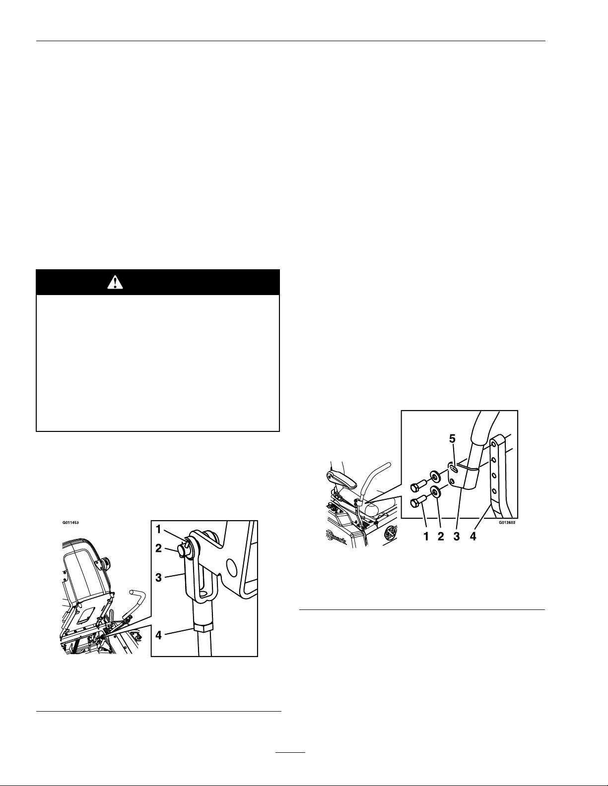
•AdjustingtheBraketoEngage:Shortenthe
linkagebyturningtheyokeclockwise.
•AdjustingtheBraketoDisengage:
Lengthenthelinkagebyturningtheyoke
counterclockwise.
8.Reinstalltheclevispinandhairpinandtighten
downthejamnut.Repeatstep6andreadjustif
necessary.
9.Whenadjustmentiscomplete,removethejack
standsorequivalentsupportandlowerthe
machine.
10.Placethemachineintothe“operating”position.
RefertotheDriveWheelReleaseV alvessection
inOperation.
MotionControlHandle
Adjustment
Adjustingtheheight:
Themotioncontrolleverscanbeadjustedhigheror
lowerformaximumoperatorcomfort.
1.Removethehardwareholdingthecontrolleverto
thecontrolarmshaft(Figure30).
6.Engage/disengagethebrakeandcheckeachdrive
tiretomakesureeachbrakeengages/disengages.
7.Ifadjustmentisnecessary,loosenthejamnut
fromtheyokeonthesidethatneedsadjustment.
Removethehairpinandclevispin(seeFigure29).
Figure29
1.Hairpin3.Y oke
2.Clevispin
4.Jamnut
Figure30
1.Bolts
2.Washer
3.Controllever
4.Controlarmshaft
5.Slottedhole
2.Movethecontrollevertothenextsetofholes.
Securetheleverwiththehardware.
3.Repeattheadjustmentfortheoppositecontrol
lever.
AdjustingtheTilt
Themotioncontrolleverscanbetiltedforeoraftfor
maximumoperatorcomfort.
38
Page 39
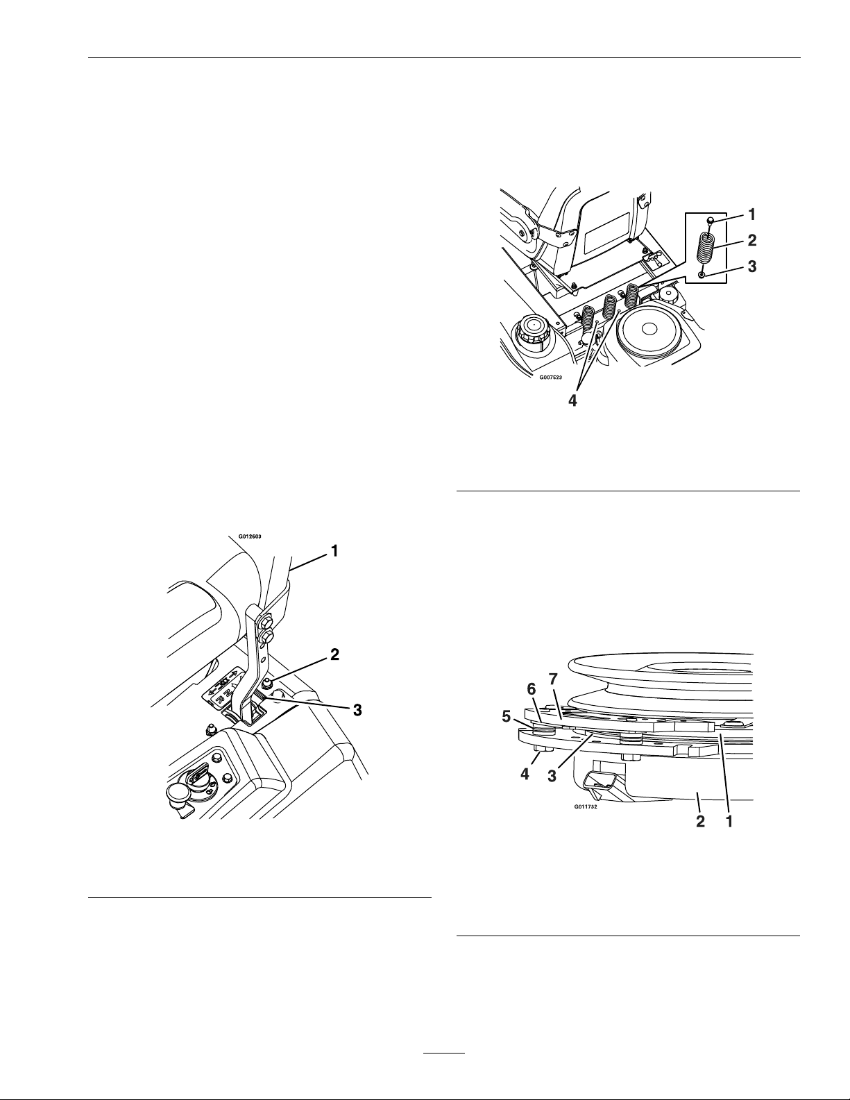
Maintenance
1.Loosentheupperboltholdingthecontrollever
tothecontrolarmshaft.
2.Loosenthelowerboltjustenoughtopivotthe
controlleverforeoraftFigure30.Tightenboth
boltstosecurethecontrolinthenewposition.
3.Repeattheadjustmentfortheoppositecontrol
lever.
FullForwardTracking
Adjustment
Ifthemachinetravelsorpullstoonesidewhenthe
motioncontrolleversareinthefullforwardposition,
adjustthecoverplates.
1.Loosenthescrewsonacoverplate(seeFigure31).
2.Slidethecoverplatebackwardorforwardto
adjustthetraveloftheleverandtightenthe
screws.
3.Drivethemachineandcheckthefullforward
tracking.
withheavieroperatorsandonroughterrain.Fewer
springsshouldbeusedwithlighteroperatorsand
whenmowingsmooth,wellestablishedlawns.Always
keepthenumberofspringsontheleftandrightside
thesamewhenaddingandremovingsprings.
Figure32
1.Bolt3.Nut
2.Spring
4.Additionalmounting
holes
4.Repeatsteps1through3untildesiredtracking
isobtained.
Figure31
1.Controlarmshaft
2.Trackingplatenut
3.Trackingplate
Uptovespringscanbesecuredtotheseatboxwith
anutandbolt,seeFigure32.
RefertothePartsManualforspringandhardware
partnumbers.
ElectricClutchAdjustment
Figure33
1.Armature5.Brakespacer
2.Fieldshell6.Re-gapshim
3.Rotor7.Brakepole
4.Brakemountingbolt
AdjustingtheSeatRide
Suspension
Thenumberofseatspringscanbechangedto
maximizeridercomfort.Morespringsshouldbeused
RemovingtheShim:
1.Stopengine,waitforallmovingpartstostop,
andremovekey.Engageparkingbrake.Allow
39
Page 40

Maintenance
G011733
1
themachinetocoolcompletelybeforestarting
theseinstructions.
2.Usingapneumaticline,blowoutanydebris
fromunderthebrakepoleandaroundthebrake
spacers.
3.Checktheconditionofthewireharnessleads,
connectors,andterminals.Cleanorrepairas
necessary.
4.Verifythat12Vispresentattheclutchconnector
whenthePTOswitchisengaged.
5.Measurethegapbetweentherotorandarmature.
Ifthegapisgreaterthan.04inch(1mm),proceed
withthefollowingsteps:
A.Loosenbothbrakemountingboltsone-half
toonefullturn(seeFigure34).
Note:DoNotremovethebrakepolefrom
theeldshell/armature.Thebrakepolehas
worntomatchthearmatureandneedsto
continuetomatchaftertheshimisremoved
toensureproperbraketorque.
asshown.(Duetothewaytherotorand
armaturefaceswear(peaksandvalleys)itis
sometimesdifculttomeasurethetruegap.)
Figure35
1.Feelergauge
Figure34
1.Brakemountingbolt
2.Shim
B.Usingneedlenosepliers,orbyhand,take
holdofthetabandremovetheshim(DoNot
discardtheshimuntilproperclutchfunction
hasbeenconrmed).
C.Usingapneumaticline,blowoutanydebris
fromunderthebrakepoleandaroundthe
brakespacers.
D.Re-torqueeachbolt(M6x1)to10ft-lb(13
N-m)+/-0.5ft-lb(0.7N-m).
E.Usinga0.010inchthickfeelergauge,verify
thatagapispresentbetweentherotorand
armaturefaceonbothsidesofthebrakepole
Figure36
1.Feelergauge
•Ifthegapislessthan0.010inch,then
reinstalltheshimandreferencethe
Troubleshootingsection.
•Ifthegapissufcient,proceedtothe
safetycheckinstepF.
F.Performthefollowingsafetycheck:
a.Sitontheseatandstarttheengine.
b.MakesurethebladesDoNotengage
withthePTOswitch“off”andtheclutch
disengaged.
Iftheclutchdoesnotdisengage,
reinstalltheshimandreferencethe
Troubleshootingsection.
c.EngageanddisengagethePTOswitch
tenconsecutivetimestoensuretheclutch
isfunctioningproperly .Iftheclutch
doesnotengageproperly,referencethe
Troubleshootingsection.
40
Page 41

Maintenance
Cleaning
CleanEngineandExhaust
SystemArea
ServiceInterval:Beforeeachuseordaily
(Mayberequiredmore
oftenindryordirty
conditions.)
CAUTION
Excessivedebrisaroundenginecoolingair
intakeandexhaustsystemareacancause
engine,exhaustarea,andhydraulicsystem
tooverheatwhichcancreatearehazard.
Cleanalldebrisfromengineandexhaust
systemarea.
1.Stopengine,waitforallmovingpartstostop,and
removekey.Engageparkingbrake.
2.Cleanalldebrisfromrotatingengineairintake
screen,aroundengineshrouding,andexhaust
systemarea.
3.Wipeupanyexcessivegreaseoroilaroundthe
engineandexhaustsystemarea.
RemoveEngineShroudsand
CleanCoolingFins
ServiceInterval:Every100hours
1.Stopengine,waitforallmovingpartstostop,and
removekey.Engageparkingbrake.
2.Removecoolingshroudsfromengineandclean
coolingns.Alsocleandust,dirtandoilfrom
externalsurfacesofenginewhichcancause
inadequatecooling.
3.Makesurecoolingshroudsarereinstalled.
Operatingtheenginewithoutcoolingshrouds
willcauseenginedamageduetooverheating.
CleanHydroFanCooling
Fins
ServiceInterval:Beforeeachuseordaily
Removingdebrisfromthehydrofancoolingnswill
allowthehydrosystemtoruncoolerandimprovethe
lifeofthehydrosystem.
1.Stopengine,waitforallmovingpartstostop,and
removekey.Engageparkingbrake.
2.LifttheseattoaccesstheLHandRHhydrodrive
area.
3.Removeaccumulateddebrisfromthehydrofan
coolingns.
CleanDebrisFromMachine
ServiceInterval:Beforeeachuseordaily
1.Stopengine,waitforallmovingpartstostop,and
removekey.Engageparkingbrake.
2.Cleanoffanyoil,debris,orgrassbuild-uponthe
machineandcuttingdeck,especiallyunderdeck
beltshields,aroundthefueltank,aroundengine
andexhaustarea.
CleanGrassBuild-UpUnder
Deck
ServiceInterval:Beforeeachuseordaily
1.Parkthemachineonalevelsurfaceanddisengage
thebladecontrolswitch.
2.Stopengine,waitforallmovingpartstostop,and
removekey.Engageparkingbrake.
3.Raisedecktothetransport(5inch(12.7cm)
cuttingheight)position.Liftthefrontofunit
andsupportunitusingjackstandsorequivalent
support.
CAUTION
Raisingthemowerdeckforserviceor
maintenancerelyingsolelyonmechanical
orhydraulicjackscouldbedangerous.The
mechanicalorhydraulicjacksmaynotbe
enoughsupportormaymalfunctionallowing
theunittofall,whichcouldcauseinjury.
DoNotrelysolelyonmechanicalorhydraulic
jacksforsupport.Useadequatejackstands
orequivalentsupport.
4.Cleanoutanygrassbuild-upfromundersideof
deckandindischargedeector.
41
Page 42

Maintenance
WasteDisposal
MotorOilDisposal
Engineoilandhydraulicoilarebothpollutantsto
theenvironment.Disposeofusedoilatacertied
recyclingcenteroraccordingtoyourstateandlocal
regulations.
BatteryDisposal
DANGER
Batteryelectrolytecontainssulfuricacid,
whichispoisonousandcancausesevere
burns.Swallowingelectrolytecanbefatalor
ifittouchesskincancausesevereburns.
•Wearsafetyglassestoshieldeyes,and
rubberglovestoprotectskinandclothing
whenhandlingelectrolyte.
•DoNotswallowelectrolyte.
Federallawstatesthatbatteriesshouldnotbeplaced
inthegarbage.Managementanddisposalpractices
mustbewithinrelevantfederal,state,orlocallaws.
Ifabatteryisbeingreplacedoriftheunitcontaining
thebatteryisnolongeroperatingandisbeing
scrapped,takethebatterytoalocalcertiedrecycling
center.Ifnolocalrecyclingisavailablereturnthe
batterytoanycertiedbatteryreseller.
42
Page 43

Troubleshooting
Troubleshooting
Important:Itisessentialthatalloperatorsafetymechanismsbeconnectedandinproperoperating
conditionpriortomoweruse.
Whenaproblemoccurs,donotoverlookthesimplecauses.Forexample:startingproblemscouldbecaused
byanemptyfueltank.
Thefollowingtablelistssomeofthecommoncausesoftrouble.Donotattempttoserviceorreplacemajor
itemsoranyitemsthatcallforspecialtimingofadjustmentprocedures(suchasvalves,governor,etc.).Have
thisworkdonebyyourEngineServiceDealer.
Note:WhendisconnectingelectricalconnectorsDONOTpullonthewirestoseparatetheconnectors.
ProblemPossibleCauseCorrectiveAction
Starterdoesnotcrank
Enginewillnotstart,startshard,orfailsto
keeprunning
1.PTOisengaged.
2.Parkingbrakeisnotengaged.2.Settheparkingbrake.
3.Driveleversarenotinneutrallock
position.
4.Batterydoesnothaveafullcharge.
5.Electricalconnectionsarecorroded,loose
orfaulty.
6.Fuseisblown.6.Replacetheblownfuse.
7.Relayorswitchisdefective.7.ContactanAuthorizedServiceDealer.
8.Faultymodule.8.Replacemodule.
1.Fueltankisempty.1.Fillthefueltank.
2.Fuelshutoffvalveisclosed.
3.Oillevelinthecrankcaseislow .
4.Thethrottleandchokearenotinthe
correctposition.
5.Dirtinfuellter.5.Replacethefuellter.
6.Dirt,water,orstalefuelisinthefuel
system.
7.Aircleanerisdirty.
8.Seatswitchisnotfunctioningproperly.
9.Electricalconnectionsarecorroded,loose
orfaulty.
10.Relayorswitchisdefective.10.ContactanAuthorizedServiceDealer.
11.Faultysparkplug.
12.Sparkplugwireisnotconnected.
13.Faultymodule.13.Replacemodule.
1.DisengagethePTO.
3.Ensurethedriveleversareintheneutral
lockposition.
4.
Chargethebattery.SeeCheck
BatteryChargeandRecommended
JumpStartingProceduresectionsin
Maintenance.
5.Checktheelectricalconnectionsfor
goodcontact.Cleanconnectorterminals
thoroughlywithelectricalcontactcleaner,
applydielectricgreaseandreconnect.
2.Openthefuelshutoffvalve.
3.Addoiltothecrankcase.
4.Besurethethrottlecontrolismidway
betweenthe“SLOW”and“F AST”
positions,andthechokeisinthe“ON”
positionforacoldengineorthe“OFF”
positionforawarmengine.
6.ContactanAuthorizedServiceDealer.
7.Cleanorreplacetheaircleanerelement.
8.Checktheseatswitchindicator.Replace
seatifneeded.
9.Checktheelectricalconnectionsfor
goodcontact.Cleanconnectorterminals
thoroughlywithelectricalcontactcleaner,
applydielectricgreaseandreconnect.
11.Clean,adjustorreplacesparkplug.
12.Checkthesparkplugwireconnection.
43
Page 44

Troubleshooting
ProblemPossibleCauseCorrectiveAction
Enginelosespower
Mowerpullsleftorright(withleversfully
forward)
Machinedoesnotdrive
Unevencuttingheight.
1.Engineloadisexcessive1.Reducethegroundspeed.
2.Aircleanerisdirty.
3.Oillevelinthecrankcaseislow .
4.Coolingnsandairpassagesforthe
engineareplugged.
5.Dirtinfuellter.5.Replacethefuellter.
6.Dirt,water,orstalefuelisinthefuel
system.
1.Tirepressureindrivetiresnotcorrect.1.Adjusttirepressureinthedrivetires.
1.Drivewheelsystemnotin“operating”
position.
2.Driveorpumpbeltisworn,looseor
broken.
3.Driveorpumpbeltisoffapulley .3.Changethebelt.
4.Brokenormissingidlerspring.
5.Hydraulicuidlevelislowortoohot.5.Addhydraulicuidtoreservoirorletit
1.Blade(s)notsharp.1.Sharpentheblade(s).
2.Cuttingblade(s)is/arebent.
3.Mowerdeckisnotlevel.3.Levelmowerdeckfromside-to-sideand
4.Undersideofmowerisdirty.4.Cleantheundersideofthemower.
5.Tirepressureindrivetiresnotcorrect.5.Adjusttirepressureinthedrivetires.
6.Bladespindlebent.6.ContactanAuthorizedServiceDealer.
7.Tipsofadjacentbladesareatanuneven
cuttingheight.Bladestipsshouldbeeven
within3/16inchwhichisapproximately
onebladethickness.
2.Cleanorreplacetheaircleanerelement.
3.Addoiltothecrankcase.
4.Removetheobstructionsfromthecooling
nsandairpassages.
6.ContactanAuthorizedServiceDealer.
1.Positiondrivewheelsystemin“operating”
position;seeDriveWheelRelease
ValvessectioninOperation.
2.Changethebelt.
4.Replacethespring.
cooldown.
2.Installnewcuttingblade(s).
front-to-rear.
7.Replaceblades,spindlesand(or)check
fordamagetomowerdeck.
Abnormalvibration
Bladesdonotrotate.
1.Cuttingblade(s)is/arebentorunbalanced.
2.Blademountingboltisloose.2.Tightentheblademountingbolt.
3.Enginemountingboltsareloose.3.Tightentheenginemountingbolts.
4.Looseenginepulley,idlerpulley,orblade
pulley.
5.Enginepulleyisdamaged.5.ContactanAuthorizedServiceDealer.
6.Bladespindleisbent.6.ContactanAuthorizedServiceDealer.
1.Deckbeltisworn,looseorbroken.1.Installnewdeckbelt.
2.Deckbeltisoffpulley.2.Installbeltonclutchanddeckpulleys,
3.Brokenormissingidlerspring.
4.Deckbeltnotroutedcorrectly.4.Refertobeltroutingdecalondeck.
1.Installnewcuttingblade(s).
4.Tightentheappropriatepulley .
idlers,andtensioningidlerperrouting
decalondeck.
3.Replacethespring.
44
Page 45
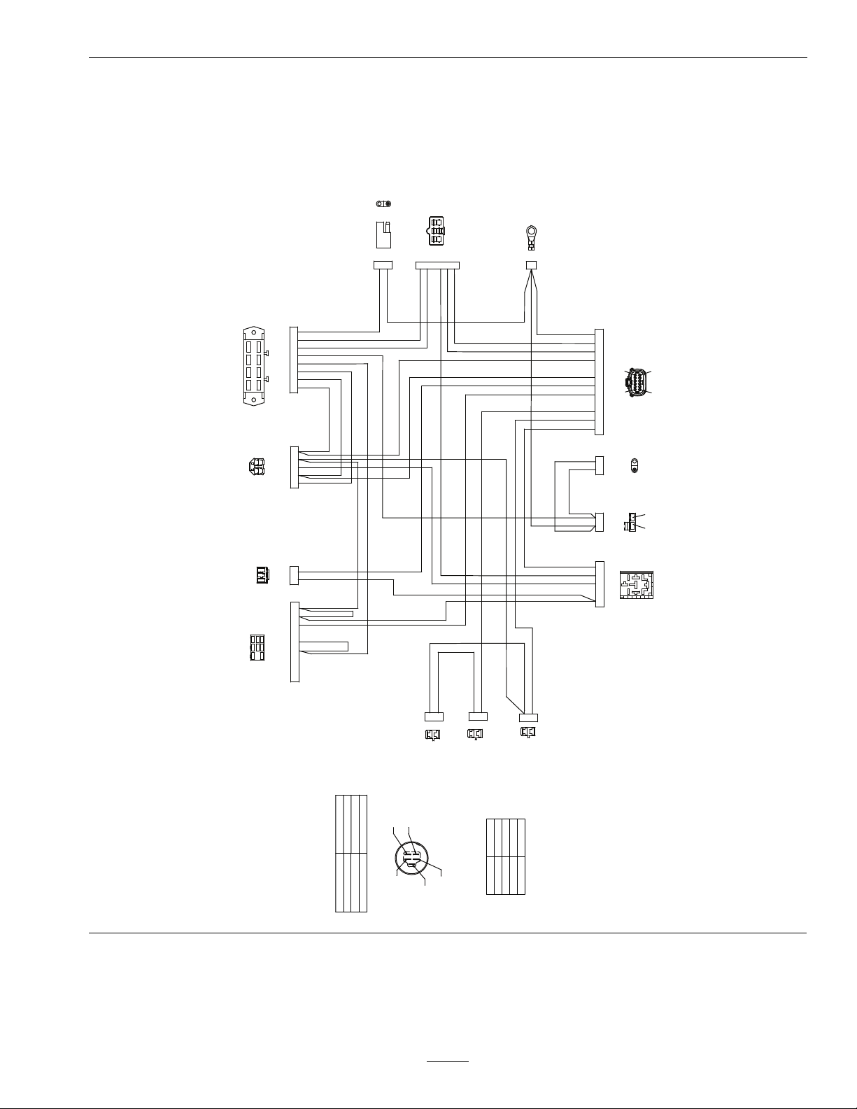
Schematics
PTO SWITCH
SEAT SWITCH
IGNITION SWITCH
REGULATOR
GROUND
LH NEUTRAL
SWITCH
RH NEUTRAL
SWITCH
BRAKE
SWITCH
HOUR METER/MODULE
MAG
FUEL SOLENOID
ENGINE
START
RELAY
A
R
IS
B
PINK
PINK
PINK
BLACK
BLACK
ORANGE
RED
RED
GRAY
VIOLET
VIOLET
RED
BROWN
BROWN
BROWN
PINK
WHITE
GREEN
LIGHT GREEN
TAN
VIOLET
YELLOW
BROWN
BLUE
START
PINK
PINK
PINK
ORANGE
ACCESSORY
BLACK
ORANGE
FUSE BLOCK
PTO
CLUTCH
TVS
DIODE
BROWN
BLACK
B+
CLUTCH
FUSE
10 A
ACCY
FUSE
15 A
REG
FUSE
20 A
B+
FUSE
25 A
2 1
1
A B
1
2
3 4 1 5 2
1
2
3 8 9 12 7 5 10 11 6 1 4 2
8 9 3 4 5 6 7 1 2
4 3 5 1 2
B
A
2 6 3 1 5
4
3 7 5 1 2 4 6 8
A B
1
2
8 6 4 2
7 5 3 1
2
5
4
3
1
2
1
3
4
9
7
8
2 1
2
1
2
1
2
1
5
2
3
4
1
A B
A
B
1
7
12
6
3
1
4 6
5
2
A
B
G012611
POSITION
CIRCUIT “MAKE”
NONE
B + R + I + A
B + R + I + S
1. OFF
2. RUN
3. START
IGNITION SWITCH
TERMINAL CONNECTIONS
TERMINAL B
TERMINAL A
ACCESSORY
BATTERY
IGNITION
START
RECTIFIER
TERMINAL I
TERMINAL S
TERMINAL R
TERMINAL I
TERMINAL A
TERMINAL R
TERMINAL B
TERMINAL S
Schematics
ElectricalDiagram
45
Page 46

Schematics
S
B IAR
KEY SW
VIEWED FROM
BACK OF SWITCH
OFF = NO CONNECTION
ON = B R I A
START = B R I S
KEY SWITCH
S
R
I
B
A
OR
OR
7
F4
ENGINE
GRD
OPTIONAL
ACCESSORIES
CONNECTOR
8
OR
PK
PK
12
5
7 9
8 5
10
6
6
B
A
BN
BN
VIO
Y
T BN OR R
30A
1
F1
2
BN
BK
BK
GROUND
PTO
NEUTRAL
BRAKE
SEAT
KEY A
B+
FUEL SOLENOID
MAGNETO
START RELAY
2
4 1
3
PK W GN
M1
HOUR METER
BK
PTO
CLUTCH
ENGINE
GND
F3
10A
BN VIO
LT GN
T
BN OR R
VIO
VIO
VIO REG
AC
AC
IGNITION
MODULES
SPARK PLUG SPARK PLUG
WIRE COLOR CODES
START
STARTER
MAG
B+
ENGINE
GND
FUEL
SOLINOID
BU
W
R
PK
GY
PK
SOLENOID
GN
U1
STARTER
SOLENOID
(OFF)
3
F2
25A
4
PK PK
8
4
7
BK
PK
R
GY
VIO
1
3
SW1
2
4
5
KEY SWITCH CONNECTION
SW2
PTO SW
(IN OFF
POSITION)
SW5
RH NEUT
SWITCH
(IN NEUT
LOCK)
SW6
SEAT SW
(W/OPER
IN SEAT)
SW4
LH NEUT
SWITCH
(IN NEUT
LOCK)
G012612
BK = BLACK
BN = BROWN
BU = BLUE
GN = GREEN
GY = GREY
LT GR = LIGHT GREEN
OR = ORANGE
PK = PINK
R = RED
T = TAN
V = VIOLET
W = WHITE
Y = YELLOW
ElectricalLogicSchematic
46
Page 47

General Warranty Conditions and Products Covered
Exmark Mfg. Co. Inc. and its affiliate, Exmark Warranty Company,
pursuant to an agreement between them, jointly warrant on the terms and
conditions herein, that we will repair, replace or adjust any
part on these
products and found by us (in the exercise of our reasonable discretion) to
be defective in factory materials or workmanship.
This warranty may only be assigned or transferred to a second (or third)
owner by an authorized Exmark dealer. The warranty period commences
upon the date of the original retail purchase.
Commercial Warranty Conditions
This warranty applies to Exmark Quest SP turf equipment sold in the
U.S. or Canada for a period of one year for commercial usage.
This warranty includes the cost of parts and labor for a period of two
years. This warranty does not cover pickup and delivery charges to and
from any authorized Exmark Service Dealer.
Consumer Warranty Conditions
This warranty applies to Exmark Quest SP turf equipment sold in the
U.S. or Canada for a period of four years or 400 hours (whichever occurs
first) for residential usage.
Residential usage means use of the product on the same lot as your home.
Use at more than one location is considered commercial use, and the
commercial use warranty detailed above would apply.
This warranty only includes the cost of parts and labor. For the first
warrantable service repair, Exmark will cover up to $45 for associated
pick-up and delivery charges to and from any authorized Exmark Service
Dealer. Additional transportation charges may apply, contact your Dealer
for details.
Warranty Exceptions
Warranty Exceptions Warranty Period
• Bags, Belts and Tires 90 days
• Battery 1 Year Prorated
• Commercial Pumps, Motors and Transmissions 1 years or 500 hours
• Consumer Pumps, Motors and Transmissions 4 years or 400 hours
• Commercial Electric Clutch 1 years or 500 hours
• Consumer Electric Clutch 4 years or 400 hours
• Engine 2 years*
* The Engine warranty is covered by the engine manufacturer. Please
refer to the engine manufacturer’s warranty statement that is included in
the literature packet.
Items and Conditions Not Covered
This warranty does not cover the following:
• Any damage or deterioration due to normal use, wear and tear, or
exposure.
• Cost of regular maintenance service or parts, such as filters, fuel,
lubricants, tune-up parts, and adjustments.
• Any product or part which has been altered or misused or required
replacement or repair due to normal wear, accidents, or lack of proper
maintenance.
• Any repairs necessary due to use of parts, accessories or supplies,
including gasoline, oil or lubricants, incompatible with the turf
equipment or other than as recommended in the operator's manual or
other operational instructions provided by Exmark.
There are no other express warranties except for engine and special
emission system coverage.
All warranty work must be performed by an authorized Exmark Service
Dealer using Exmark approved replacement parts.
Instructions for Obtaining Warranty Service
The product must be registered with original proof of purchase by an
Exmark Service Dealer before obtaining any warranty service.
Contact any Exmark Service Dealer to arrange service at their dealership.
To locate a dealer convenient to you, access our website at
www.exmark.com. U.S. or Canada customers may also call
402-223-6375.
If for any reason you are dissatisfied with the Service Dealer’s analysis or
with the assistance provided, contact us at:
Exmark Customer Service Department
The Exmark Warranty Company
2101 Ashland Avenue
Beatrice, NE 68310
402-223-6375 or
service@exmark.com
Owner’s Responsibilities
If your product requires warranty service it must be returned to an
authorized Exmark service dealer within the warranty period. This
warranty extends only to turf equipment operated under normal
conditions. You must read the operator’s manual. You must also properly
service and maintain your Exmark product as described in the operator’s
manual. Such routine maintenance, whether performed by a dealer or by
you, is at your expense.
General Conditions
The sole liability of Exmark and Exmark Warranty Company with respect
to this warranty shall be repair or replacement of defective components as
set forth herein. Neither Exmark nor Exmark Warranty Company
shall be liable for any incidental or consequential loss or damage.
Such damages include but are not limited to:
• Expenses related to gasoline, oil or lubricants.
• Travel time, overtime, after hours time or other extraordinary repair
charges or charges relating to repairs or replacements outside of
normal business hours at the place of business of the authorized
Exmark Service Dealer.
• Rental of like or similar replacement equipment during the period of
any warranty, repair or replacement work.
• Any telephone or telegram charges or travel charges.
• Loss or damage to person or property other than that covered by the
terms of this warranty.
• Any claims for lost revenue, lost profit or additional cost as
a result of a claim of breach of warranty.
• Attorney's fees.
No Claim of breach of warranty shall be cause for cancellation or
rescission of the contract of sale of any Exmark mower.
All implied warranties of merchantability (that the product is fit for
ordinary use) and fitness for use (that the product is fit for a
particular purpose) are limited to the duration of the express
warranty.
Some states do not allow exclusions of incidental or consequential
damages, or limitations on how long an implied warranty lasts, so the
above exclusions and limitations may not apply to you.
This warranty gives you specific legal rights, and you may also have
other rights which vary from state to state.
Quest SP Turf Equipment
1 Year Limited Commercial Warranty
4 Year or 400 Hours Limited Consumer Warranty
G4500-592
47
Page 48

Notes:
48
Page 49

ServiceRecord
Date:
DescriptionofWorkDone:ServiceDoneBy:
49
Page 50

50
Page 51

G011841
Figure37
Thispagemaybecopiedforpersonaluse.
1.Themaximumslopeyoucansafelyoperatethemachineonis15degrees.Usetheslopeindicatortodeterminethe
degreeofslopeofhillsbeforeoperating.DoNotoperatethismachineonaslopegreaterthan15degrees.Fold
alongtheappropriatelinetomatchtherecommendedslope.
2.Alignthisedgewithaverticalsurface,atree,building,fencepole,etc.
3.Exampleofhowtocompareslopewithfoldededge.
51
Page 52

MI D-MOUNT RIDING ACCE SSORIES AND OPTIONS
SEE EXMARK’S COMPLETE LINE OF ACCESSORIES AND OPTIONS
WALK-BEHIND ACCESSORIES AND OPTIONS
GRASS CATCHER
MICRO-MULCH SYSTEM
TURF STRIPER
STANDON
CUSTOM RIDE SEAT SUSPENSION SYSTEM
FULL SUSPENSION SEAT
DECK LIFT ASSIST KIT
HITCH KIT
LIGHT KIT
12
V POWER PORT
MICRO-MULCH SYSTEM
OPERATOR CONTROLLED DISCHARGE
ROLL OVER PROTECTION SYSTEM (ROPS)
SUN SHADE
TRASH CONTAINER
TURF STRIPER
ULTRA VAC COLLECTION SYSTEM
ULTRA VAC QUICK DISPOSAL SYSTEM
OU T-F RONT RIDING AC CESSORIES A ND OPTIONS
CUSTOM RIDE SEAT SUSPENSION SYSTEM
DUAL-TAIL WHEEL
FLOOR PAN EXTENDER
HITCH KIT
LIGHT KIT
MICRO-MULCH SYSTEM
ROLL OVER PROTECTION SYSTEM (ROPS)
SNOW BLADE
SNOWBLOWER
SUN SHADE
TRASH CONTAINER
ULTRA VAC COLLECTION SYSTEM
ULTRA VAC QUICK DISPOSAL SYSTEM
WEATHER CAB
PlaceModelNo.andSerialNo.
LabelHere(IncludedintheLiterature
Pack)orFillinBelow
ModelNo.EngineSerialNo.(E/No)
SerialNo.
©2010ExmarkMfg.Co.,Inc.
IndustrialParkBox808
Beatrice,NE68310
AllRightsReserved
DatePurchased
EngineModelNo.andSpec.No.
PartNo.4500-582Rev .A
(402)223-6300
Fax(402)223-5489
PrintedintheUSA
www.exmark.com
 Loading...