

Page 1
QUEST®
FRONTSTEER
ForSerialNos.
315,000,000&Higher
PartNo.4502-392Rev.B
Page 2

WARNING
CALIFORNIA
Proposition65Warning
Thisproductcontainsachemical
orchemicalsknowntotheStateof
Californiatocausecancer,birthdefects,
orreproductiveharm.
Theengineexhaustfromthisproduct
containschemicalsknowntotheStateof
Californiatocausecancer,birthdefects,
orotherreproductiveharm.
Important:Theengineinthisproductisnot
equippedwithasparkarrestermufer.Itisa
violationofCaliforniaPublicResourceCode
(CPRC)Section4442touseoroperatethis
engineonanyforest-covered,brush-covered,
orgrass-coveredlandasdenedinCPRC4126.
Otherstatesorfederalareasmayhavesimilar
laws.
Toacquireasparkarresterforyourunit,seeyour
EngineServiceDealer.
Thissparkignitionsystemcomplieswiththe
CanadianstandardICES-002.Cesystèmed’allumage
parètincelledevèhiculeestconformeàlanorme
NMB-002duCanada.
TheenclosedEngineOwner’sManualis
suppliedforinformationregardingTheU.S.
EnvironmentalProtectionAgency(EPA)and
theCaliforniaEmissionControlRegulationof
emissionsystems,maintenanceandwarranty.
KeepthisengineOwner’sManualwithyourunit.
ShouldthisengineOwner’sManualbecome
damagedorillegible,replaceimmediately.
Replacementsmaybeorderedthroughthe
enginemanufacturer.
Labeledpowerratingsaresuppliedbytheengine
manufacturerinaccordancewithSAEtesting
andgross/netpowerratingstandards(J1940,
J1995,J1349).
Exmarkreservestherighttomakechangesor
addimprovementstoitsproductsatanytime
withoutincurringanyobligationtomakesuch
changestoproductsmanufacturedpreviously.
Exmark,oritsdistributorsanddealers,accept
noresponsibilityforvariationswhichmaybe
evidentintheactualspecicationsofitsproducts
andthestatementsanddescriptionscontained
inthispublication.
©2015ExmarkMfg.Co.,Inc.
IndustrialParkBox808
Beatrice,NE68310
2
Contactusatwww.Exmark.com.
PrintedintheUSA
AllRightsReserved
Page 3
Introduction
CONGRATULATIONSonthepurchaseofyour
ExmarkMower.Thisproducthasbeencarefully
designedandmanufacturedtogiveyouamaximum
amountofdependabilityandyearsoftrouble-free
operation.
Thismanualcontainsoperating,maintenance,
adjustment,andsafetyinstructionsforyourExmark
mower.
BEFOREOPERATINGYOURMOWER,
CAREFULLYREADTHISMANUALINITS
ENTIRETY.
Byfollowingtheoperating,maintenance,andsafety
instructions,youwillprolongthelifeofyourmower,
maintainitsmaximumefciency,andpromotesafe
operation.
Important:Tomaximizesafety,performance,
andproperoperationofthismachine,itis
essentialthatalloperatorscarefullyreadand
fullyunderstandthecontentsoftheOperator’s
manualprovidedwiththeproduct.Safe
operationofExmarkequipmentisessential.
Failuretocomplywiththeoperatinginstructions
orreceivepropertrainingmayresultininjury.
Gotohttp://www.Exmark.comforadditional
safeoperationinformation,suchassafetytips,
trainingmaterials,andOperator’smanuals.
Ifadditionalinformationisneeded,orshould
yourequiretrainedmechanicservice,contactyour
authorizedExmarkequipmentdealerordistributor.
AllExmarkequipmentdealersanddistributorsare
keptinformedofthelatestmethodsofservicing
andareequippedtoprovidepromptandefcient
serviceintheeldorattheirservicestations.They
carryamplestockofservicepartsorcansecurethem
promptlyforyoufromthefactory.
AllExmarkpartsarethoroughlytestedandinspected
beforeleavingthefactory,however,attentionis
requiredonyourpartifyouaretoobtainthefullest
measureofsatisfactionandperformance.
Wheneveryouneedservice,genuineExmarkparts,
oradditionalinformation,contactanAuthorized
ServiceDealerorExmarkCustomerServiceandhave
themodelandserialnumbersofyourproductready.
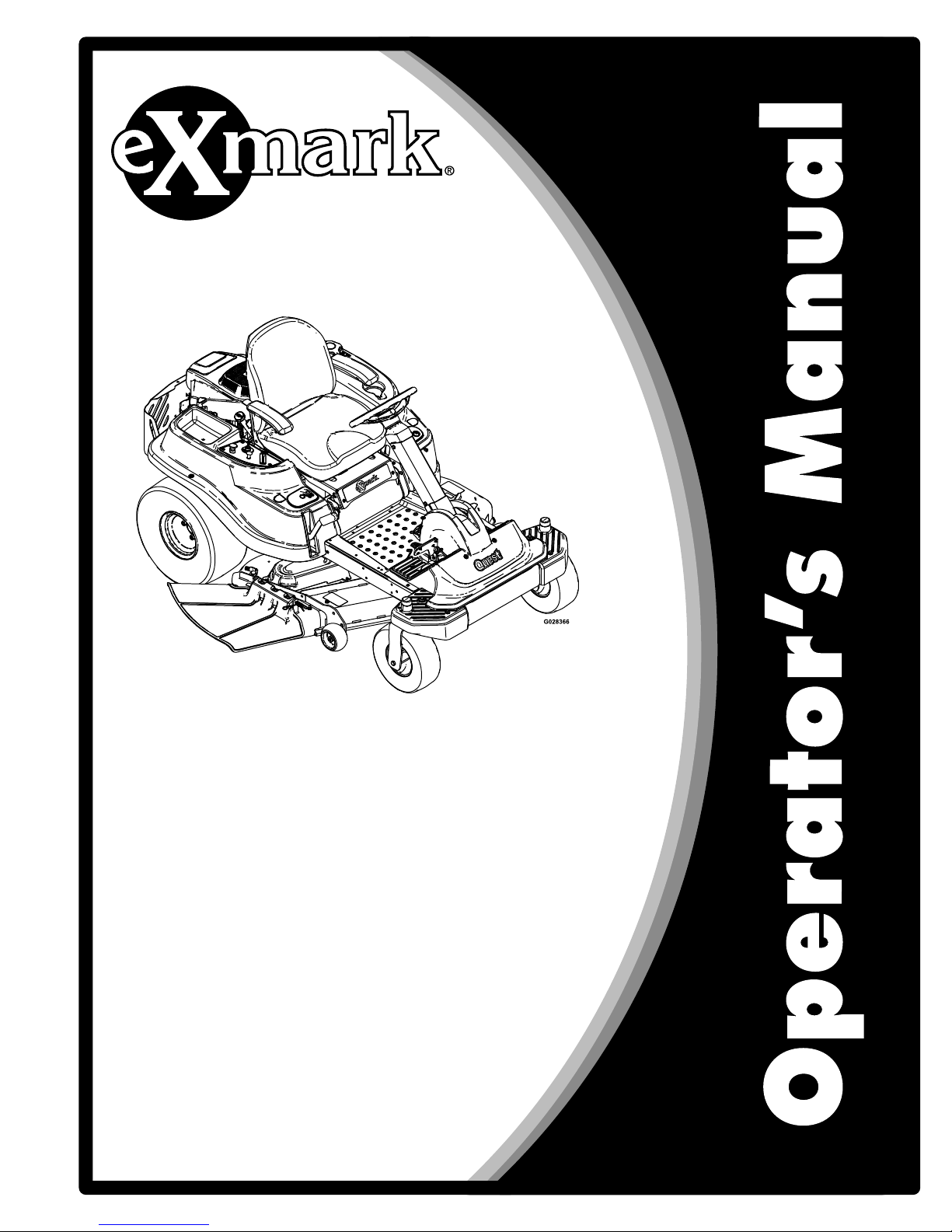
Figure1identiesthelocationofthemodelandserial
numbersontheproduct.Writethenumbersinthe
spaceprovided.
G014523
1
Figure1
1.Modelandserialnumberlocation
ModelNo.
SerialNo.
3
Page 4

Contents
Introduction...........................................................3
Safety.....................................................................5
SafetyAlertSymbol.........................................5
SafeOperatingPractices..................................5
SafetyandInstructionalDecals.......................9
Specications........................................................17
ModelNumbers.............................................17
Systems..........................................................17
Dimensions....................................................18
TorqueRequirements.....................................19
ProductOverview.................................................19
Operation..............................................................20
Controls.........................................................20
OperatingInstructions...................................22
ThinkSafetyFirst...........................................22
RecommendedGasoline.................................22
CheckingtheEngineOilLevel........................24
StartingtheEngine.........................................24
OperatingtheParkingBrake
(SmartPark
™
).............................................25
OperatingtheBlades......................................25
StoppingtheEngine.......................................25
TheSafetyInterlockSystem............................26
DrivingForwardorBackward.........................27
StoppingtheMachine.....................................27
MowinginReverse.........................................28
AdjustingtheHeight-of-Cut...........................28
AdjustingtheAnti-ScalpRollers......................29
PositioningtheSeat........................................29
ChangingtheSeatRideSuspension.................29
PositioningtheSteeringWheel........................30
PushingtheMachinebyHand.........................30
SideDischarge................................................31
TransportingtheMachine...............................31
LoadingtheMachine......................................32
OperatingTips..............................................33
Maintenance..........................................................35
RecommendedMaintenanceSchedule(s)............36
PremaintenanceProcedures...............................37
RaisingtheSeat..............................................37
RaisingtheFrontoftheMachine.....................37
PeriodicMaintenance........................................37
Lubrication.....................................................37
EngineMaintenance.......................................38
ServicingtheEngineOil.................................40
ServicingtheSparkPlug-Exmark708cc
Engine.......................................................45
ServicingtheSparkPlug-Kohler
Engine.......................................................46
CleaningtheBlowerHousing..........................48
FuelSystemMaintenance...............................48
ServicingtheEmissionsFilter.........................48
ElectricalSystemMaintenance........................49
ChargingtheBattery.......................................49
DriveSystemMaintenance.............................52
CheckingtheTirePressure.............................52
CheckingtheHydraulicOilLevel–50Inch
Only...........................................................52
ChangingtheHydraulicSystemFilterand
Oil––50InchOnly.....................................53
MowerMaintenance.......................................55
ServicingtheCuttingBlades...........................55
LevelingtheMowerDeck...............................57
MowerBeltMaintenance................................60
ReplacingtheDischargeDeector..................62
Cleaning............................................................63
CleanGrassBuild-UpUnderDeck.................63
CleanEngineandExhaustSystem
Area...........................................................63
CleanDebrisFromMachine...........................64
Storage..................................................................65
CleaningandStorage......................................65
Troubleshooting....................................................66
Schematics............................................................68
4
Page 5

Safety
Safety
SafetyAlertSymbol
Thismanualidentiespotentialhazardsandhas
safetymessagesidentiedbythesafetyalertsymbol
(Figure2),whichsignalsahazardthatmaycause
seriousinjuryordeathifyoudonotfollowthe
recommendedprecautions.
Figure2
SafetyAlertSymbol
Thismanualusestwootherwordstohighlight
information.Importantcallsattentiontospecial
mechanicalinformationandNoteemphasizes
generalinformationworthyofspecialattention.
Thismachinemeetsorexceedsthesafety
specicationsoftheAmericanNational
StandardsInstituteB71.1ineffectatthetime
ofproduction.However,improperuseor
maintenancebytheoperatororownercan
resultininjury.Toreducethepotentialfor
injury,complywiththesesafetyinstructions
andalwayspayattentiontothesafetyalert
symbol,whichmeansCAUTION,WARNING,
orDANGER-"personalsafetyinstruction."
Failuretocomplywiththeinstructionmayresult
inpersonalinjuryordeath.
SafeOperatingPractices
ThefollowinginstructionsarefromANSIstandard
B71.1.
Thisproductiscapableofamputatinghandsand
feetandthrowingobjects.Alwaysfollowallsafety
instructionstoavoidseriousinjuryordeath.
GeneralOperation
•Read,understand,andfollowallinstructionsin
theoperator’smanualandonthemachinebefore
starting.
•DoNotplacehandsorfeetnearrotatingpartsor
underthemachine.Keepclearofthedischarge
openingatalltimes.
•Allowonlyresponsibleadultswhoarefamiliar
withtheinstructionstooperatethemachine.
•Cleartheareaofobjectssuchasrocks,toys,wire,
etc.,whichcouldbepickedupandthrownbythe
blade.
•Besuretheareaisclearofotherpeoplebefore
mowing.Stopthemachineifanyoneentersthe
area.
•Nevercarrypassengers.
•DoNotmowinreverseunlessabsolutely
necessary.Alwayslookdownandbehindbefore
andwhilebackingup.
•Beawareofthemowerdischargedirectionand
DoNotpointitatanyone.Avoiddischarging
materialagainstawallorobstruction.Material
mayricochetbacktowardtheoperator.Stopthe
bladeswhencrossinggravelsurfaces.
•DoNotoperatethemowerwithouteitherthe
entiregrasscollectionsystemorthedischarge
deectorinplace.
•Bealert,slowdownandusecautionwhen
makingturns.Lookbehindandtothesidebefore
changingdirections.
•Neverleavearunningmachineunattended.
Alwaysturnoffblades,engageparkingbrake,
stopengine,andremovekeybeforedismounting.
•Turnoffbladeswhennotmowing.Stopthe
engine,waitforallpartstocometoacomplete
stop,engageparkingbrake,andremovekey
beforecleaningthemachine,removingthegrass
oruncloggingthedeector.
•Operatethemachineonlyindaylightorgood
articiallight.
•DoNotoperatethemachinewhileunderthe
inuenceofalcoholordrugs.
•Watchfortrafcwhenoperatingnearorcrossing
roadways.
•Useextracarewhenloadingorunloadingthe
machineintoatrailerortruck
•Alwaysweareyeprotectionwhenoperatingthe
mower.
•Dataindicatesthatoperators,age60yearsand
above,areinvolvedinalargepercentageofriding
mower-relatedinjuries.Theseoperatorsshould
evaluatetheirabilitytooperatetheridingmower
5
Page 6

Safety
safelyenoughtoprotectthemselvesandothers
fromseriousinjury.
•Alwaysfollowtherecommendationsforwheel
weightsorcounterweights.
•Lightningcancausesevereinjuryordeath.If
lightningisseenorthunderisheardinthearea,
DoNotoperatethemachine;seekshelter.
SlopeOperation
Slopesareamajorfactorrelatedtolossofcontrol
andtip-overaccidents,whichcanresultinsevere
injuryordeath.Operationonallslopesrequiresextra
caution.Ifyoucannotbackuptheslopeorifyoufeel
uneasyonit,DoNotmowit.
•DoNotmowslopesgreaterthan15degrees.
•Watchforditches,holes,rocks,dips,andrisesthat
changetheoperatingangle,asroughterraincould
overturnthemachine.
•Choosealowgroundspeedsoyouwillnothave
tostopwhileoperatingonaslope.
•DoNotmowslopeswhengrassiswet.Slippery
conditionsreducetractionandcouldcausesliding
andlossofcontrol.
•Reducespeedanduseextremecautiononslopes.
•DoNotmakesuddenturnsorrapidspeed
changes.
•Removeormarkobstaclessuchasrocks,tree
limbs,etc.fromthemowingarea.Tallgrasscan
hideobstacles.
•Avoidsuddenstartswhenmowinguphillbecause
themowermaytipbackwards.
•Beawarethatoperatingonwetgrass,acrosssteep
slopesordownhillmaycausethemowertolose
traction.Lossoftractiontothedrivewheelsmay
resultinslidingandalossofbrakingandsteering.
•Alwaysavoidsuddenstartingorstoppingona
slope.Iftireslosetraction,disengagetheblades
andproceedslowlyofftheslope.
•Useextremecarewithgrasscollectionsystemsor
otherattachments.Thesecanchangethestability
ofthemachineandcauselossofcontrol.
•DoNottrytostabilizethemachinebyputting
yourfootontheground.
•DoNotmowneardrop-offs,ditches,steepbanks
orwater.Wheelsdroppingoveredgescancause
rollovers,whichmayresultinseriousinjury,death
ordrowning.
•Useawalkbehindmowerand/orahandtrimmer
onslopesgreaterthan15degrees,neardrop-offs,
ditches,steepbanksorwater.
Children
Tragicaccidentscanoccuriftheoperatorisnot
alerttothepresenceofchildren.Childrenareoften
attractedtothemachineandthemowingactivity.
Neverassumethatchildrenwillremainwhereyou
lastsawthem.
•Keepchildrenoutofthemowingareaandunder
thewatchfulcareofanotherresponsibleadult,
nottheoperator.
•Bealertandturnthemachineoffifchildrenenter
thearea.
•Beforeandwhilebackingorchangingdirection,
lookbehind,down,andside-to-sideforsmall
children.
•Nevercarrychildren,evenwiththebladesoff.
Theymayfalloffandbeseriouslyinjuredor
interferewithsafemachineoperation.
•Childrenwhohavebeengivenridesinthepast
maysuddenlyappearinthemowingareafor
anotherrideandberunoverorbackedoverby
themower.
•Neverallowchildrentooperatethemachine.
•Useextracarewhenapproachingblindcorners,
shrubs,trees,theendofafenceorotherobjects
thatmayobscurevision.
TowingSafety
•Donotattachtowedequipmentexceptatthe
hitchpoint.
•Followtheattachmentmanufacturer's
recommendationforweightlimitsfortowed
equipmentandtowingonslopes.Towedweight
mustnotexceedtheweightofthemachine,
operator,andballast.Usecounterweightsor
wheelweightsasdescribedintheattachment,or
inthepullingmachineOperator’sManual.
•Neverallowchildrenorothersinorontowed
equipment.
•Onslopes,theweightofthetowedequipment
maycauselossoftraction,increasedriskof
6
Page 7

Safety
rollover,andlossofcontrol.Reducethetowed
weightandslowdown.
•Stoppingdistanceincreaseswiththeweightofthe
towedload.Travelslowlyandallowextradistance
tostop.
•Makewideturnstokeeptheattachmentclearof
themachine.
Service
SafeHandlingofGasoline
Toavoidpersonalinjuryorpropertydamage,use
extracarewhenhandlinggasolineandotherfuels.
Theyareammableandthevaporsareexplosive.
•Extinguishallcigarettes,cigars,pipesandother
sourcesofignition.
•Useonlyanapprovedcontainer.
•Neverremovethegascaporaddfuelwhenthe
engineisrunning.Allowtheenginetocoolbefore
refueling.
•Neverrefuelthemachineindoors.
•Neverstorethemachineorfuelcontainerinside
wherethereisanopename,suchasnearawater
heaterorfurnace.
•Neverllcontainersinsideavehicleorona
truckortrailerwithaplasticliner.Alwaysplace
containersonthegroundawayfromyourvehicle
beforelling.
•Removegas-poweredequipmentfromthetruck
ortrailerandrefuelitontheground.Ifthisis
notpossible,thenrefuelsuchequipmentwitha
portablecontainer,ratherthanfromagasoline
dispensernozzle.
•Keepthenozzleincontactwiththerimofthe
fueltankorcontaineropeningatalltimesuntil
thefuelingiscomplete.DoNotuseanozzle
lock-opendevice.
•Iffuelisspilledonclothing,changeclothing
immediately.
•Neveroverllthefueltank.Replacegascapand
tightensecurely.
GeneralService:
•Neverrunamachineinsideaclosedarea.
•Keepnutsandboltstight,especiallytheblade
attachmentbolts.Keepequipmentingood
condition.
•Neverinterferewiththeintendedfunctionofa
safetydeviceorreducetheprotectionprovided
byasafetydevice.Checktheirproperoperation
regularly.
•Keepthemachinefreeofgrass,leaves,orother
debrisbuild-up.Cleanupoilorfuelspillageand
fuelsoakeddebris.Allowthemachinetocool
beforestoring.
•Stopandinspecttheequipmentifyoustrikean
object.Repair,ifnecessary,beforerestarting.
•Nevermakeanyadjustmentsorrepairswiththe
enginerunning.
•Grasscollectionsystemcomponentsaresubject
towear,damageanddeterioration,whichcould
exposemovingpartsorallowobjectstobe
thrown.Frequentlycheckcomponentsand
replacewithmanufacturers’recommendedparts,
whennecessary.
•Mowerbladesaresharpandcancut.Wrapthe
bladesorweargloves,anduseextracautionwhen
servicingthem.
•Checkforproperbrakeoperationfrequently .
Adjustandserviceasrequired.
•Maintainorreplacesafetyandinstructiondecals
asnecessary.
•UseonlygenuineExmarkreplacementpartsto
ensurethatoriginalstandardsaremaintained.
ExmarkRidingMowerSafety
Thefollowinglistcontainssafetyinformationspecic
toExmarkproductsorothersafetyinformationthat
youmustknowthatisnotincludedintheANSI
standards.
•Onlyadultsandmatureteenagersshouldoperate
amower,andevenmatureteenagersshouldhave
adultsupervision.Besureateenager:
1.hasreadandunderstandstheOperator's
Manualandrecognizestherisksinvolved;
2.issufcientlymaturetousecaution;and
3.isofsufcientsizeandweighttooperate
thecontrolscomfortablyandtomanagethe
mowerwithouttakingrisks.
•Engineexhaustcontainscarbonmonoxide,which
isanodorless,deadlypoisonthatcankillyou.Do
Notrunengineindoorsorinanenclosedarea.
7
Page 8

Safety
•Parkmachineonlevelground.Stoptheengine,
waitforallmovingpartstostop,engageparking
brake,disconnectsparkplugwire(s)andremove
keybeforeperforminganyservice,repairs,
maintenanceoradjustments.
•Keephands,feet,hair,andlooseclothingaway
fromattachmentdischargearea,undersideof
mowerandanymovingpartswhileengineis
running.
•DoNottouchequipmentorattachmentparts
whichmaybehotfromoperation.Allowtocool
beforeattemptingtomaintain,adjustorservice.
•Batteryacidispoisonousandcancauseburns.
Avoidcontactwithskin,eyes,andclothing.
Protectyourface,eyes,andclothingwhen
workingwithabattery.
•Batterygasescanexplode.Keepcigarettes,sparks
andamesawayfrombattery.
•UseonlyExmarkapprovedattachments.
Warrantymaybevoidedifusedwithunapproved
attachments.
•Ifloadingthemachineontoatrailerortruck,use
asingle,full-widthramponly.Therampangle
shouldnotexceed15degrees.
Note:Theleftandrightsidesofthemachineare
determinedwhilesittingintheseatinthenormal
operatingposition
8
Page 9
Safety
SafetyandInstructionalDecals
Safetydecalsandinstructionsareeasilyvisibletotheoperatorandarelocatednearanyarea
ofpotentialdanger.Replaceanydecalthatisdamagedorlost.
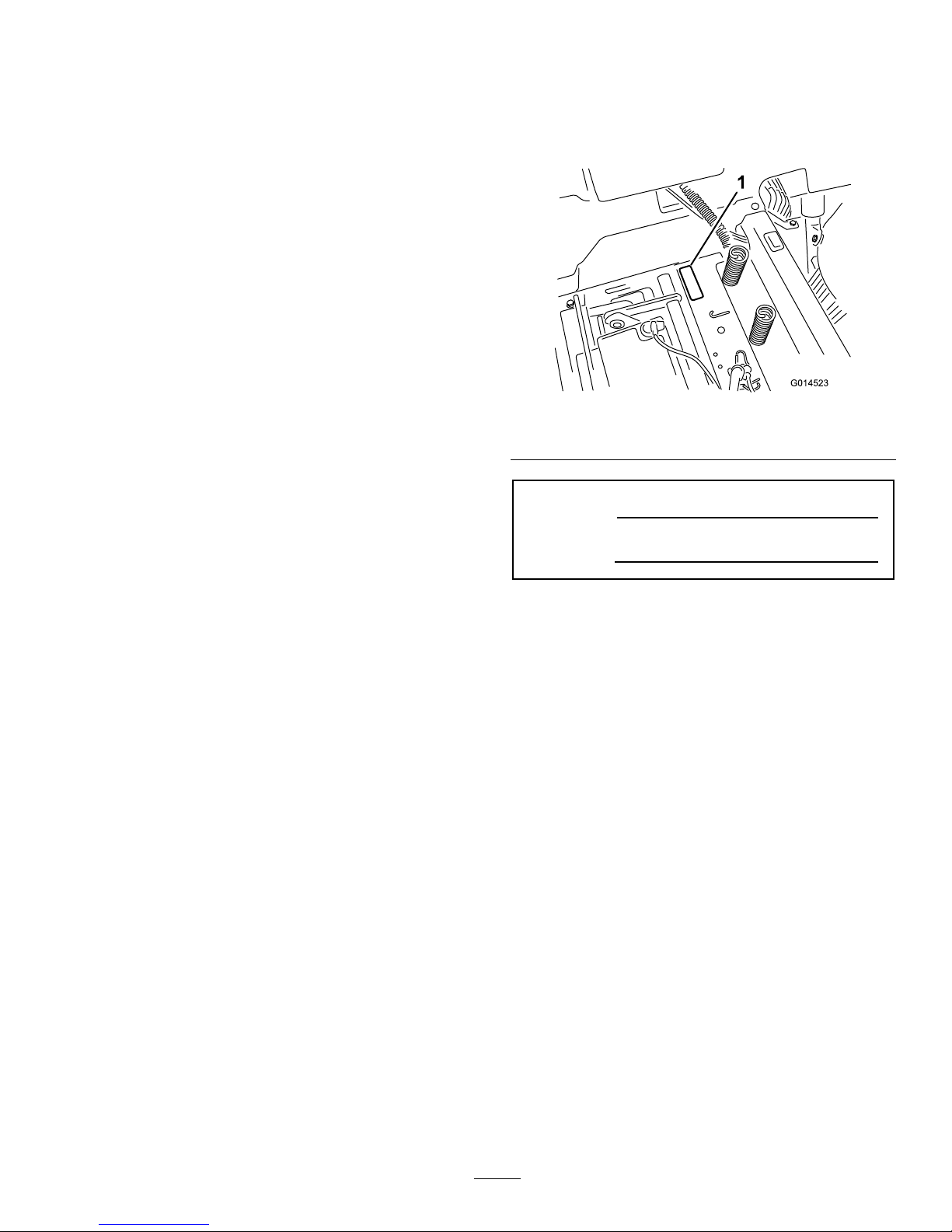
93-7009
1.Warning—don'toperatethemowerwiththedeectorup
orremoved;keepthedeectorinplace.
2.Cutting/dismembermenthazardofhandorfoot,mower
blade—stayawayfrommovingparts.
99-3943
ForModelswith50InchDecks
1.Engine
105-7015
ForModelswith42InchDecks
1.Beltrouting
106-8717
1.Readtheinstructionsbeforeservicingorperforming
maintenance.
2.Checktirepressureevery25operatinghours.
3.Greaseevery25operatinghours.
4.Engine
9
Page 10
Safety
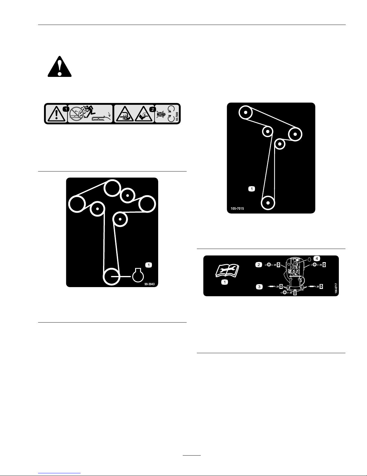
110-6691
1.Thrownobjecthazard—keepbystandersasafedistance
fromthemachine.
2.Thrownobjecthazard,mower—donotoperatewithout
thedeector,dischargecover,orgrasscollection
systeminplace.
3.Cutting/dismembermentofhandorfoot—stayaway
frommovingparts.
112-9840
1.ReadtheOperator's
Manual.
3.Removetheignitionkey
andreadtheinstructions
beforeservicingor
performingmaintenance.
2.Heightofcut
114-1606
1.Entanglementhazard,belt—keepallguardsinplace.
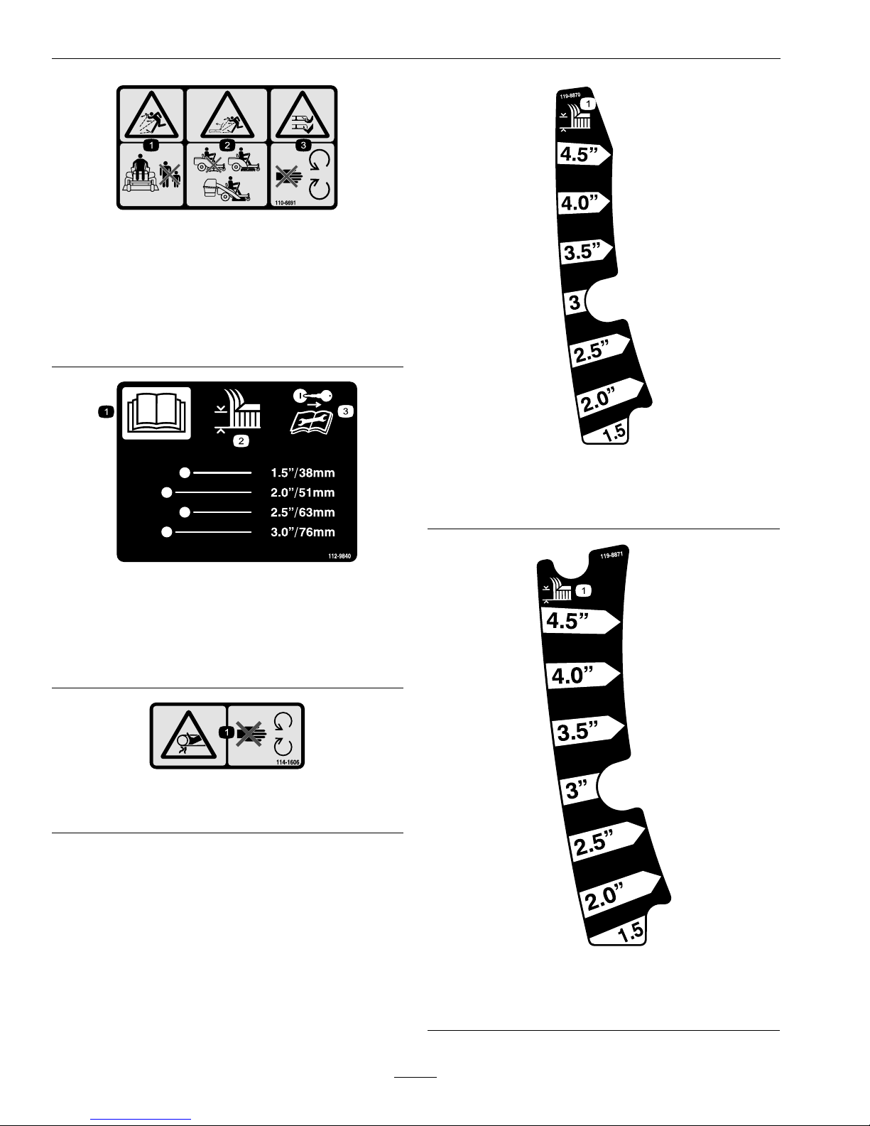
119-8870
50-inchModel
1.Height-of-cut
119-8871
42InchModel
1.Height-of-cut
10
Page 11
Safety
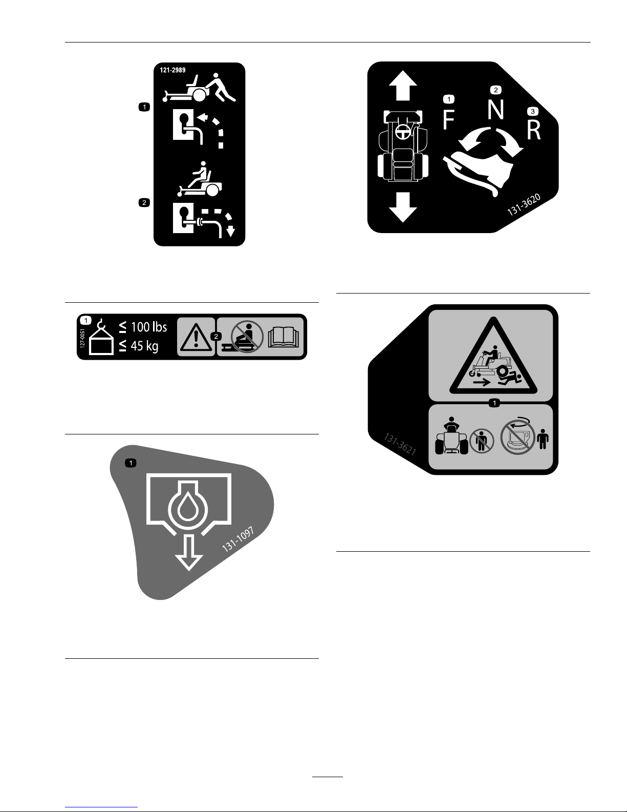
121-2989
1.Bypassleverpositionfor
pushingthemachine
2.Bypassleverpositionfor
operatingthemachine
127–0051
1.Maximumcarrierframe
loadislessthanorequal
to100lbs(45kg).
2.Warning—donotsitor
rideonthecarrierframe;
readtheOperator’s
Manual.
131-1097
42and50InchModelswithExmarkEngine
1.Oildrain
131-3620
1.Pedalposition—forward
3.Pedalposition—reverse
2.Pedalposition—neutral
131-3621
1.Crushing/dismembermenthazard—keepbystanders
awayfromthemachine;donotactivateKeyChoice
®
switch(allowsmowinginreverse)withbystanders
nearby.
11
Page 12
Safety
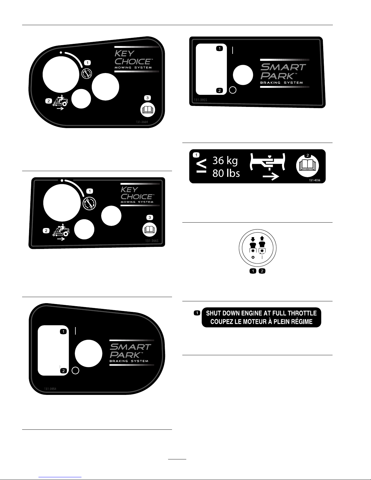
131-3664
50inchModel
1.Spinningblade3.Operator'sManual
2.Reverse
131-3665
42inchModel
1.SpinningBlade3.ReadtheOperator's
Manual.
2.Reverse
131-3954
50inchModel
1.On2.Off
131-3955
42inchModel
1.On2.Off
131-4036
1.T oworpullweightsless
thanorequalto36kg
(80lbs).
2.ReadtheOperator's
Manual.
PTOSwitchSymbols
1.PTO–disengage2.PTO–engage
ExmarkEnginesOnly
1.Shutdownengineatfullthrottle
12
Page 13
Safety
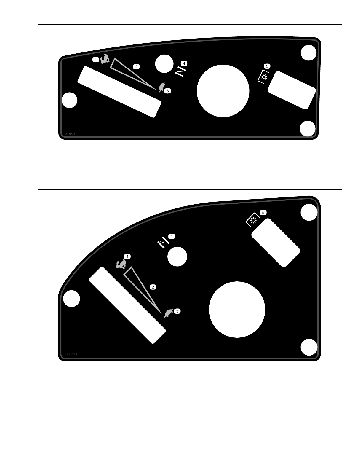
121-0772
42InchModelswithExmarkEngine
1.Fast
4.Choke
2.Continuousvariablesetting5.Powertake-off(PTO),Bladecontrolswitch
3.Slow
121-0773
50InchModelswithExmarkEngine
1.Fast
4.Choke
2.Continuousvariablesetting5.Powertake-off(PTO),Bladecontrolswitch
3.Slow
13
Page 14
Safety
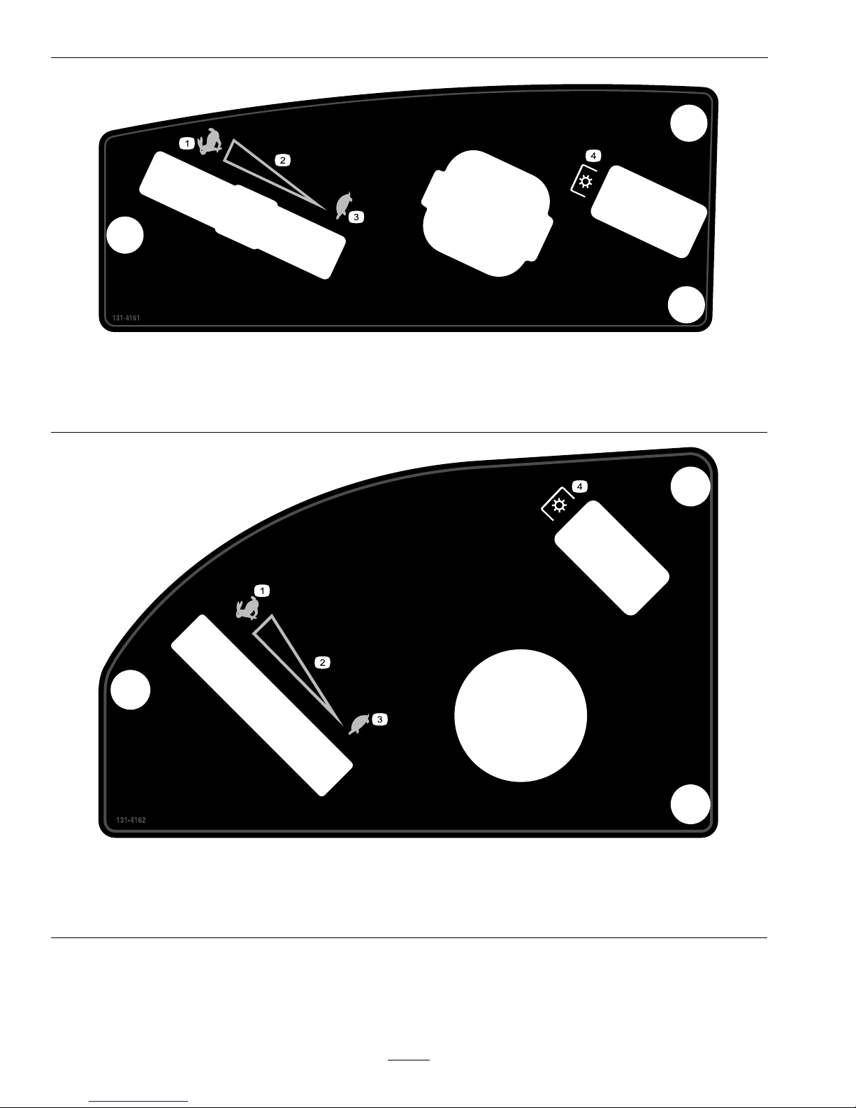
131-4161
42InchModelswithKohlerEngine
1.Fast
3.Slow
2.Continuousvariablesetting4.Powertake-off
131-4162
50InchModelswithKohlerEngine
1.Fast
3.Slow
2.Continuousvariablesetting4.Powertake-off
14
Page 15
Safety
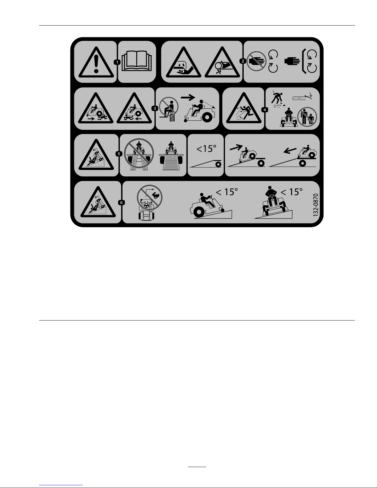
132-0870
1.Warning—readtheOperator'sManual.4.Thrownobjecthazard—keepbystandersasafedistance
fromthemachine,pickupdebrisbeforeoperating,keep
deectorinplace.
2.Cutting/dismembermenthazard,mowerblade;
entanglementhazard,belt—stayawayfrommovingparts,
keepallguardsandshieldsinplace.
5.Ramphazard—Whenloadingontoatrailer,donotuse
splitramps.Onlyuseafullwidthrampwideenoughfor
themachine.Rampanglewiththegroundshouldbeless
than15degrees.Backuptherampanddriveforwardoff
theramp.
3.Crushing/dismembermenthazardofbystanders,in
reverseandforward—donotcarrypassengers,look
behindanddownwhenreversing.
6.Tippinghazard—donotturnathighspeeds;donotuse
withslopesgreaterthan15degrees;onlyuseonslopes
lessthan15degrees.
15
Page 16

Safety
BatterySymbols
Someorallofthesesymbolsareonyourbattery.
1.Explosionhazard
5.ReadtheOperator'sManual.
9.Flusheyesimmediatelywithwater
andgetmedicalhelpfast.
2.Nore,openames,orsmoking6.Keepbystandersasafedistance
fromthebattery.
10.Containslead;donotdiscard.
3.Causticliquid/chemicalburnhazard
7.Weareyeprotection;explosive
gasescancauseblindnessand
otherinjuries.
4.Weareyeprotection8.Batteryacidcancauseblindnessor
severeburns.
16
Page 17

Specications
Specications
ModelNumbers
SerialNos:315,000,000andHigher
QSS708GEM42200;QSS708GEM50200;QSS725GKC42200;QSS725GKC50200
Systems
Engine
•EngineSpecications:SeeyourEngineOwner’s
Manual
•EngineOilType:Exmark4-CyclePremium
EngineOil
•RPM:
FullSpeed:3300±100(max)RPM(NoLoad)
Idle:1650(min)RPM
FuelSystem
•Capacity:2.9gal.(11L)
•FuelRecommendations:
–Forbestresults,useonlyclean,fresh,unleaded
gasolinewithanoctaneratingof87orhigher
((R+M)/2ratingmethod).
–Oxygenatedfuelwithupto10%ethanolor
15%MTBEbyvolumeisacceptable.
–DoNotuseethanolblendsofgasoline(such
asE15orE85)withmorethan10%ethanol
byvolume.Performanceproblemsand/or
enginedamagemayresultwhichmaynotbe
coveredunderwarranty.
–DoNotusegasolinecontainingmethanol.
–DoNotstorefueleitherinthefueltankor
fuelcontainersoverthewinterunlessafuel
stabilizerisused.
–DoNotaddoiltogasoline.
•FuelFilter:In-line
ElectricalSystem
•ChargingSystem:FlywheelAlternator
•ChargingCapacity:
–Exmark:15amps
–Kohler:12amps
•BatteryType:195CCA
•BatteryVoltage:12Volt
•Polarity:NegativeGround
•Fuses:One30amp,one25amp;bladetype
SafetyInterlockSystem
•PTOmustbedisengaged,tractionpedalin
neutral,andparkingbrakeengagedtostartengine.
(Itisnotnecessaryfortheoperatortobeinthe
seattostarttheengine.)
•OperatormustbeinseatwhenPTOisengaged
ortractionpedalismovedforward/reverseor
enginewillstop.
OperatorControls
•SteeringWheel:Controlsthedirectionand
turningradius.Reartiresoperateindependently
allowingzero-turns.
Note:Steeringwheelisadjustabletothree
operatingpositionsandone,full-upposition.
•Traction-controlfootpedal:Controlstheforward
andreversemotionalongwithspeed.
•PTOEngagementSwitch:Engageselectricclutch
(todrivebelt)whichengagesmowerblades.
•DeckHeightAdjustmentLever:Setscutting
heighttodesiredposition.
Seat
•Type:Twotoneupholsteredhighback,foam
paddedseatwithspringsuspensionandarmrests.
•Mounting:Hingedtotiltupforaccesstobattery
andothercomponents.Adjustableforeandaft.
•Armrests:Standard–paddedip-uparmrests.
•SeatSafetySwitch:IncorporatedintotheSafety
InterlockSystem.
HydrostaticGroundDriveSystem
•HydrostaticPumps:
–42inchunit:TwoHydroGearZT2200
Integrateddrivesystems.
17
Page 18

Specications
–50inchunit:TwoHydroGearZT2800
Integrateddrivesystems.
•HydraulicOilType:ExmarkPremiumHydroOil.
•HydraulicFilter—50inch:P/N109-3321
•Speeds:
–0-7.0mph(11.3km/hr)forward.
–0-5.0mph(8.0km/hr)reverse.
•Drivewheelreleases,locatedonleftandright
sidesofenginedeck,allowmachinetobemoved
whentheengineisnotrunningandbrakeisoff.
TiresandWheels
Drive
Pneumatic(Air-Filled)
DeckSize
4250
Quantity
22
Tread
TurfTechTL
KendaSuper
Turf
Size18x7.50-820x8-10
PlyRating
44
Pressure
13psi
(90kPa)
13psi
(90kPa)
FrontCaster
Pneumatic(Air-Filled)
DeckSize
4250
Quantity
22
TreadRibbedRibbed
Size11x4-513x5-6
PlyRating
22
Pressure
13psi
(90kPa)
13psi
(90kPa)
CuttingDeck
•CuttingWidth:
–42inchDeck:42inches(107cm)
–50inchDeck:50inches(127cm)
•Discharge:Side
•BladeSize:
–42inchDeck:21.60inches(54.9cm)–Qty:2
–50inchDeck:17.50inches(44.5cm)–Qty:3
•BladeSpindles:Solidsteelspindleswithno
maintenancebearings.
•DeckDrive:Electricclutchmountedonvertical
engineshaft.Bladesaredrivenbyonebelt
(w/self-tensioningidler)directfromtheengine.
•Deck:Fulloatingdeckisattachedtoout-front
supportframe.Maximumturfprotectionis
providedwithanti-scalprollers.
Deckdesignallowsforbagging,mulchingorside
discharge.
•DeckDepth:
–42inchDeck:4.0inches(10.2cm)
–50inchDeck:4.0inches(10.2cm)
•CuttingHeightAdjustment:Ahanddeckliftlever
isusedtoadjustthecuttingheightfrom11/2
inch(3.8cm)to41/2inches(11.4cm)in1/2
inch(1.3cm)increments.
•MulchingKit:Optional.
Dimensions
OverallWidth:
42inchDeck50inchDeck
WithoutDeck39.0inches
(99cm)
46.3inches
(118cm)
DeectorUp43.2inches
(110cm)
50.6inches
(129cm)
DeectorDown54.1inches
(137cm)
61.7inches
(157cm)
OverallLength:
42inchDeck50inchDeck
81.7inches(208cm)81.7inches(208cm)
OverallHeight:
AllUnits
42.8inches(109cm)
TreadWidth:(CentertoCenterof
Tires,Widthwise)
42inchDeck50inchDeck
DriveWheels31.5inches
(80cm)
37.4inches
(95cm)
CasterWheels30.8inches
(78cm)
34.0inches
(86cm)
18
Page 19
ProductOverview
WheelBase:(CenterofCasterTireto
CenterofDriveTire)
42InchDeck50InchDeck
52.5inches(133cm)50.5inches(128cm)
CurbWeight:
42inchDeck50inchDeck
645lb(293kg)713lb(323kg)
TorqueRequirements
BoltLocation
Torque
SpindlePulleyNut35-65ft-lb(47-88N-m)
BladeMountingBolt35-65ft-lb(47-88N-m)
EngineMountingBolts
330-400in-lb(37-45N-m)
WheelLugNuts
70-90ft-lb(95-122N-m)
ClutchMounting
Bolt(securedwith
threadlocker)
50-60ft-lb(68-81N-m)
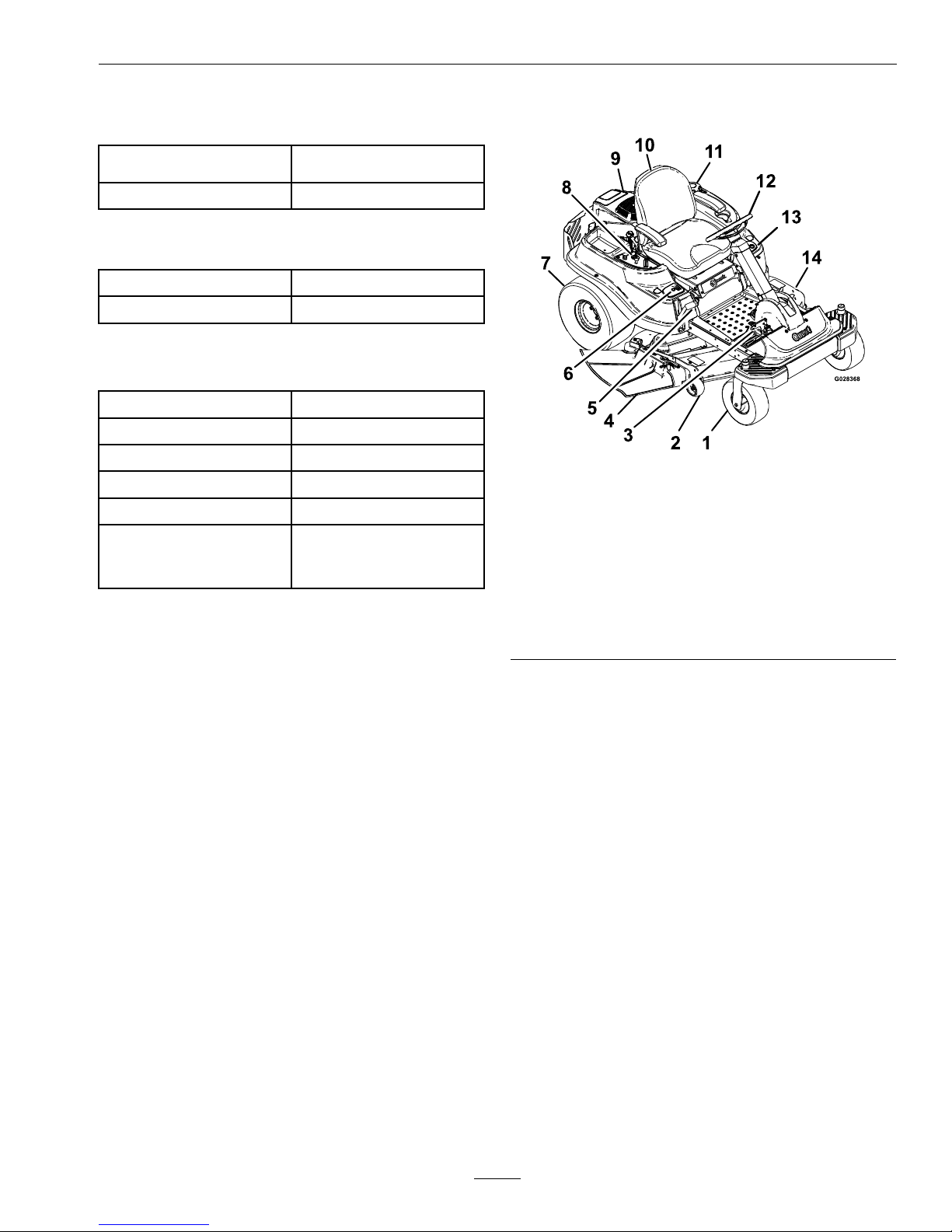
ProductOverview
Figure3
1.Frontcasterwheel
8.Controlpanel
2.Anti-scalproller9.Engine
3.Traction-controlpedal
10.Seat
4.Dischargedeector
11.Fueltank
5.Deckheightadjustment
lever
12.Steeringwheel
6.SmartPark™switch13.KeyChoice
®
control
7.Reardrivewheel14.Mowerdeck
19
Page 20
Operation
Operation
Controls
Note:Becomefamiliarwithallofthecontrols
beforeyoustarttheengineandoperatethemachine.
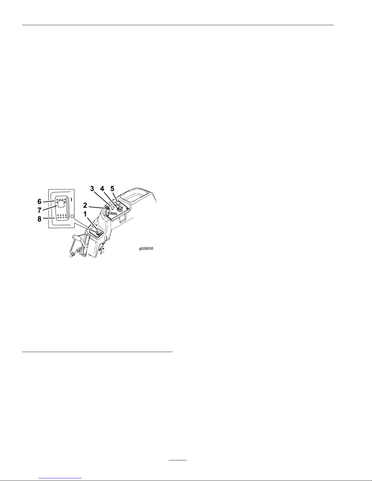
IgnitionSwitch
Locatedoncontrolpanel.
Theignitionswitchisusedtostartandstopthe
engine.Theswitchhasthreepositions“OFF”,
“RUN”and“START”.Insertkeyintoswitchand
rotateclockwisetothe“ON”position.Rotate
clockwisetothenextpositiontoengagethestarter
(keymustbeheldagainstspringpressureinthis
position).
Figure4
ExmarkEnginewith50InchDeckShown
1.SmartPark™(Parkingbrake)switch
2.Chokecontrol
3.Throttlelever
4.Ignitionswitch
5.Bladecontrolswitch(powertake-off)
6.Parkingbrake-On
7.Parkingbrake-indicatorlight
8.Parkingbrake-Off
Note:Brakemustbeengaged,traction-controlpedal
inneutral,andPTOswitch“OFF”tostartengine.
(Itisnotnecessaryfortheoperatortobeintheseat
tostarttheengine.)
Turningthekeytothe“OFF”positionwillstopthe
engine;however,alwaysremovethekeywhenleaving
themachinetopreventsomeonefromaccidentally
startingtheengine.
BladeControlSwitch(Power
Take-Off)
Locatedonthecontrolpanel.
Thebladecontrolswitch,representedbyapower
take-off(PTO)symbol,engagesanddisengages
powertothemowerblades(seeFigure4).
Pulluponthebladecontrolswitchto“ON”to
engagetheblades.
Pushdownonthebladecontrolswitchto“OFF”
todisengagetheblades.
ThrottleLever
Locatedoncontrolpanel.
Thethrottleisusedtocontrolenginespeed.Moving
throttleleverforwardwillincreaseenginespeedand
movingthrottlelevertotherearwilldecreaseengine
speed(seeFigure4).
ChokeControl
Thechokeisusedtoaidinstartingacoldengine.Do
Notrunawarmenginewiththechokeinthe“ON”
position.
•UnitswithExmarkEngines:Pullinguponthe
chokecontrolwillputthechokeinthe“ON”
positionandpushingdownthecontrolwillput
thechokeinthe“OFF”position.
•UnitswithKohlerEngines:Theengineis
integratedwithanauto-choke.Thereisnoneed
tomanuallyprimeorchoketheseengines.
SteeringWheel
Thesteeringwheelislocatedinfrontoftheseat.
Thesteeringwheelcontrolsthedirectionandturning
radius.Thereartiresoperateindependentlyofeach
other,likeazero-turn,whichallowsforsharpturns
andtoturnindifferentdirectionsquickly .
Thesteeringwheelhasthreepositionsforoperation
andone,full-upposition.Usethefull-uppositionfor
steppingonandoffthemachineandgettingoutof
theseat.Whenoperatingthemachine,positionthe
steeringwheelwhereyouhavethebestcontrolofthe
machineandaremostcomfortable.
20
Page 21
Operation
Traction-ControlPedal
Locatedtotherightofthesteeringwheelcolumn
base.
Pressingthetopofthetraction-controlpedalmoves
theunitforward.Pressingthebottomofthepedal
movesthemachinerearward.Releasingpressureoff
ofthepedalslowsthemachine.
Note:Thefartherthepedalispressedineither
direction,thefasterthemachinewillmoveinthat
direction.
Removingyourfootandreleasingallpressurefrom
thepedalplacesthetraction-controlpedalinneutral.
SmartPark™Switch
Locatedonthelowerrightcontrolpanel.
Theparkingbrakeisactivatedelectronically.
Engagetheparkingbrakebyoneofthefollowing
actions:
•PressingtheSmartPark
™
switchtothe“ON”
position(seeFigure4).
•Theparkingbrakeengagesautomaticallywhenthe
operatorleavestheseatandthetraction-control
pedalisinneutralposition.
•Theparkingbrakeautomaticallyengages5to6
secondsaftertheignitionswitchisturnedtothe
“OFF”position(ifnotalreadyengaged).
Note:ThelightontheSmartPark
™
switchwill
illuminatewhentheparkingbrakeisengaged.
Disengagetheparkingbrakebyoneofthefollowing
actions:
•PresstheSmartPark
™
switchtothe“OFF”
positionwiththekeyintherunposition.
•Tapthetraction-controlpedalforwardorreverse.
Makesuretheparkingbrakeengageswhenyoustop
themachineorleaveitunattended.Theunitmustbe
tieddownandbrakeengagedwhentransporting.
DeckHeightAdjustmentLever
LocatedonrightsideinfrontoftheSmartPark™
switch(seeFigure4).
Pulltheleverinwardandrearwardtoraisethecutting
deck.Allowthehandletomoveforwardtolowerthe
cuttingdeck.Movethedeckheightadjustmentlever
outwardatthedesiredheight-of-cut.Onlyadjustthe
heightofcutwhilethemachineisnotmoving.
KeyChoice
®
Switch
Thisswitchallowsyoutomowinreversewhenitis
activated.Toactivateit,turntheswitchto“ON”and
releaseitafterthepowertake-off(PTO)isengaged.
Todeactivateit,disengagethePTO.
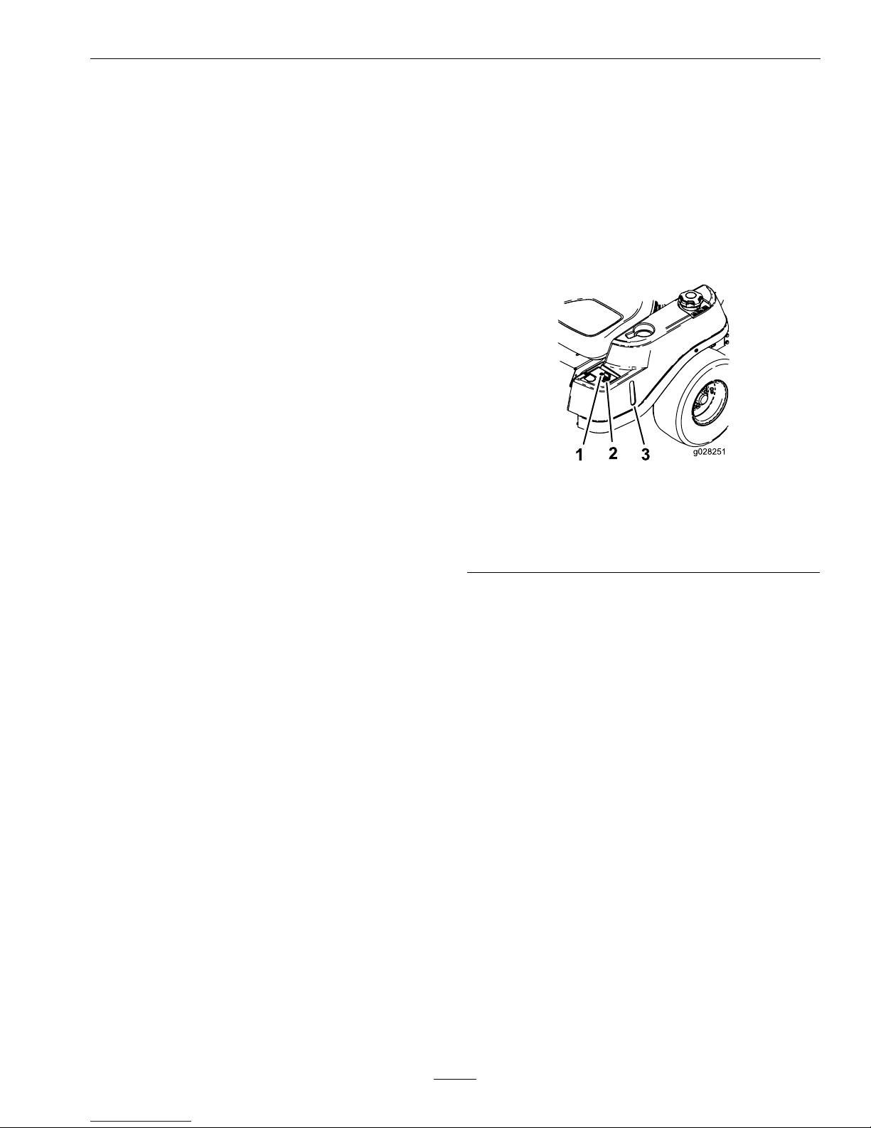
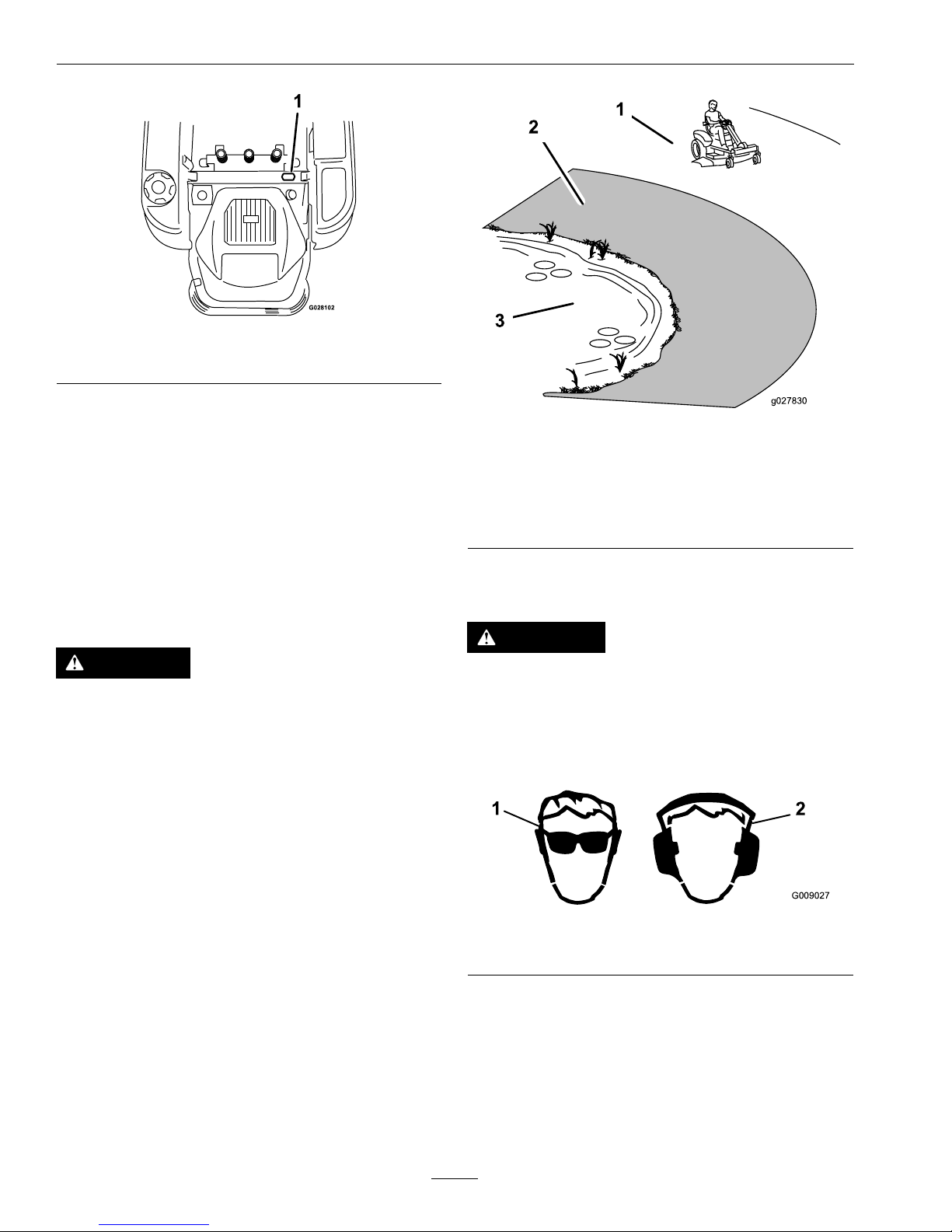
Figure5
1.Operating–in–Reverse
warninglight
3.Fuelwindow
2.KeyChoice
®
switch(blue
incolor)
Operating–in–ReverseWarningLight
LocatednexttotheKeyChoice
®
switch
TheOperating–in–Reversewarninglightwill
illuminatewhenevertheKeyChoice
®
switchisused
todeactivatetheoperating–in–reverseinterlock.Itis
areminderthattheinterlocksystemisdeactivated.
ThelightgoesoutwheneverthePTOisdisengaged
ortheengineisshutoff.Whenthelightison,look
behindanduseextracautionwhenbacking.
FuelWindow
Locatedontheleftsideofthemachine.
Thefuelwindowcanbeusedtodeterminethe
amountoffuelinthetank.
HourMeter
Thehourmeterrecordsthenumberofhourswhen
theoperatorisintheseatandtheignitionswitchisin
the“ON”position(Figure6).
21
Page 22
Operation
Figure6
1.Hourmeterlocationbehindtheseat
OperatingInstructions
ThinkSafetyFirst
Note:Determinetheleftandrightsidesofthe
machinefromthenormaloperatingposition.
Pleasecarefullyreadallofthesafetyinstructionsand
decalsinthesafetysection.Knowingthisinformation
couldhelpyou,yourfamily ,petsorbystandersavoid
injury.
DANGER
Mowingonwetgrassorsteepslopescancause
slidingandlossofcontrol.Wheelsdropping
overedgescancauserollovers,whichmayresult
inseriousinjury,deathordrowning.Alossof
tractionisalossofsteeringcontrol.
Toavoidlossofcontrolandpossibilityofrollover:
•DoNotmowneardrop-offsornearwater.
•DoNotmowslopesgreaterthan15degrees.
•Reducespeedanduseextremecautionon
slopes.
•Whenmowingslopes,graduallyworkfrom
lowertohigherareasontheincline.
•Avoidsuddenturnsorrapidspeedchanges.
•Turnup,intoaninclinewhenchanging
directionsonslopes.Turningdowntheslope
reducestraction.
•Attachmentschangethehandling
characteristicsofthemachine.Useextra
cautionwhenusingattachmentswiththe
machine.
g027830
Figure7
1.SafeZone–usetheQuesthere.
2.DangerZone–Usewalkbehindmowerand/orhand
trimmeronslopesgreaterthan15degrees,near
drop-offsandwater.
3.Water
Seeinsidebackcovertodeterminetheapproximate
slopeangletobemowed.
CAUTION
Thismachineproducessoundlevelsinexcessof
85dBAattheoperatorsearandcancausehearing
lossthroughextendedperiodsofexposure.
Wearhearingprotectionwhenoperatingthis
machine.
G009027
1
2
Figure8
1.Wearsafetyglasses
2.Wearhearingprotection
RecommendedGasoline
Fillfueltankonlevelground.SeeFuel
RecommendationsintheSpecicationssectionfor
additionalgasolineinformation.
DoNotaddoiltogasoline.
22
Page 23

Operation
DoNotoverllfueltank.Fillthefueltanktothe
bottomofthellerneck.Theemptyspaceinthe
tankallowsgasolinetoexpand.Overllingmayresult
infuelleakageordamagetotheengineoremission
system.
DANGER
Incertainconditionsgasolineisextremely
ammableandvaporsareexplosive.
Areorexplosionfromgasolinecanburnyou,
others,andcausepropertydamage.
•Fillthefueltankoutdoorsonlevelground,in
anopenarea,whentheengineiscold.Wipe
upanygasolinethatspills.
•Neverrellthefueltankordrainthemachine
indoorsorinsideanenclosedtrailer.
•DoNotllthefueltankcompletelyfull.Add
gasolinetothefueltankuntilthebodyofthe
tankisfullbutfueldoesnotlltheneckof
thetank.Thisemptyspaceinthetankallows
gasolinetoexpand.
•Neversmokewhenhandlinggasoline,and
stayawayfromanopenameorwhere
gasolinefumesmaybeignitedbyspark.
•Storegasolineinanapprovedcontainerand
keepitoutofthereachofchildren.Never
buymorethana30-daysupplyofgasoline.
•DoNotoperatewithoutentireexhaustsystem
inplaceandinproperworkingcondition.
DANGER
Incertainconditionsduringfueling,static
electricitycanbereleasedcausingasparkwhich
canignitegasolinevapors.Areorexplosion
fromgasolinecanburnyouandothersandcause
propertydamage.
•Alwaysplacegasolinecontainersonthe
groundawayfromyourvehiclebeforelling.
•DoNotllgasolinecontainersinsidea
vehicleoronatruckortrailerbedbecause
interiorcarpetsorplastictruckbedliners
mayinsulatethecontainerandslowtheloss
ofanystaticcharge.
•Whenpractical,removegas-powered
equipmentfromthetruckortrailerandrefuel
theequipmentwithitswheelsontheground.
•Ifthisisnotpossible,thenrefuelsuch
equipmentonatruckortrailerfroma
portablecontainer,ratherthanfroma
gasolinedispensernozzle.
•Ifagasolinedispensernozzlemustbeused,
keepthenozzleincontactwiththerimofthe
fueltankorcontaineropeningatalltimes
untilfuelingiscomplete.DoNotuseanozzle
lockopendevice.
WARNING
Gasolineisharmfulorfatalifswallowed.
Long-termexposuretovaporshascausedcancer
inlaboratoryanimals.Failuretousecautionmay
causeseriousinjuryorillness.
•Avoidprolongedbreathingofvapors.
•Keepfaceawayfromnozzleandgas
tank/containeropening.
•Keepawayfromeyesandskin.
•Neversiphonbymouth.
UsingStabilizer/Conditioner
Useafuelstabilizer/conditionerinthemachineto
providethefollowingbenets:
•Keepsgasolinefreshduringstorageof30daysor
less.Forlongerstorageitisrecommendedthat
thefueltankbedrained.
•Cleanstheenginewhileitruns.
•Eliminatesgum-likevarnishbuildupinthefuel
system,whichcauseshardstartingAddthe
23
Page 24

Operation
correctamountofgasstabilizer/conditionerto
thegas.
Note:Afuelstabilizer/conditionerismosteffective
whenmixedwithfreshgasoline.Tominimizethe
chanceofvarnishdepositsinthefuelsystem,usefuel
stabilizeratalltimes.
FillingtheFuelTank
Makesuretheengineisshutoffandtheparkingbrake
isengaged.Tankmaximumcapacityis2.9gallons.
Note:Usethefuelwindowtoverifythepresenceof
gasolinebeforellingthetank.
Important:DoNotoverllfueltank.Fillthe
fueltanktothebottomofthellerneck.The
emptyspaceinthetankallowsthefueltoexpand.
Overllingmayresultinfuelleakageordamage
totheengineoremissionsystem.
1.Shuttheengineoffandengageparkingbrake.
2.Cleanaroundthefueltankcapandremovethe
cap(seeFigure9).
g027243
A
B
E
D
C
Figure9
3.Addunleadedregulargasolineuntilthefuel
reachesthebaseofthellerneckanddoesnotll
theneckofthetank.Thisspaceatthebaseof
thellerneckallowsgasolinetoexpand.DoNot
llthefueltankcompletelyfull.Overllingmay
resultinfuelleakageordamagetotheengineor
emissionssystem.
4.Installthefueltankcapsecurelyandtightenuntil
it“clicks”.Wipeupanygasolinethatmayhave
spilled.
CheckingtheEngineOil
Level
Beforeyoustarttheengineandusethemachine,
checktheoillevelintheenginecrankcase;referto
CheckingtheOilLevelinEngineMaintenance
section.
StartingtheEngine
1.Sitdownontheseat,makesurethe
traction-controlpedalisinneutralandtheparking
brakeisengaged.
2.Disengagethebladesbymovingthebladecontrol
switchto“OFF”.
Figure10
ExmarkEnginewith50InchDeckShown
1.Ignition5.Throttlelever
2.Off6.Chokecontrol
3.Run
7.Bladecontrolswitch–Off
position
4.Start
3.Engagethechokebeforestartingacoldengine
(ifapplicable).
Note:Awarmorhotenginemaynotrequire
choking.
4.Turntheignitionkeyto“START”toenergizethe
starter.Whentheenginestarts,releasethekey.
24
Page 25

Operation
Important:DoNotengagethestarterfor
morethan5secondsatatime.Iftheengine
failstostart,allowa60secondcool-down
periodbetweenattempts.Failuretofollow
theseinstructionscanburnoutthestarter
motor.
5.Oncetheenginestarts,graduallypushdownthe
chokecontrol(ifapplicable)astheenginewarms.
Iftheenginestallsorhesitates,slightlypullthe
controlupforafewseconds.
OperatingtheParkingBrake
(SmartPark
™
)
Theparkingbrakeisactivatedelectronically.
Engagetheparkingbrakebyoneofthefollowing
actions:
•PressingtheSmartPark
™
switchtothe“ON”
position(Figure4).
•Theparkingbrakeengagesautomaticallywhen
theoperatorleavestheseatandthetraction
controlpedalisintheneutralposition.
•Theparkingbrakeautomaticallyengages5to6
secondsaftertheignitionswitchisturnedtothe
“OFF”position(ifnotalreadyengaged).
Disengagetheparkingbrakebyoneofthefollowing
actions:
•Tapthetraction-controlpedalforwardorreverse.
•Pressingthebrakeswitchtothe“OFF”position
(Figure4).
OperatingtheBlades
Thebladecontrolswitch,representedbyapower
take-off(PTO)symbol,engagesanddisengages
powertothemowerblades.Thisswitchcontrols
powertoanyattachmentsthatdrawpowerfromthe
engine,includingthemowerdeckandcuttingblades.
EngagingtheBlades
1.Releasethetraction-controlpedaltoplacethe
machineinneutral.
2.Movethethrottlemidwaybetweenthe“SLOW”
and“FAST”positions.
Note:Alwaysengagethebladeswiththethrottle
inthemidwayposition.
3.Pulloutonthebladecontrolswitch,tothe“ON”
position,toengagetheblades.
Figure11
ExmarkEnginewith50InchDeckShown
1.Throttle–Midwayposition2.Bladecontrol
switch—Onposition
4.Movethrottletofullforwardpositionbefore
mowing.
DisengagingtheBlades
Setthethrottletothemidwayposition.Pushthe
bladecontrolswitchto“OFF”todisengagethe
blades(Figure10).
StoppingtheEngine
1.Bringtheunittoafullstop.
2.Disengagetheblades.
3.Releasethetraction-controlpedaltoplacethe
machineinneutralandengagetheparkingbrake.
4.Adjustthethrottle.
•ForAllEnginesexceptExmark:Placethe
throttlemidwaybetweenthe“SLOW”and
“FAST”positions.
•ForExmarkEngines:Placethethrottleinthe
“FAST”position.
5.Allowtheenginetorunforaminimumof15
seconds,thenturntheignitionswitchtothe
“OFF”positiontostoptheengine.
6.Removethekeytopreventchildrenorother
unauthorizedpersonsfromstartingengine.
25
Page 26

Operation
TheSafetyInterlockSystem
WARNING
Ifsafety-interlockswitchesaredisconnected
ordamaged,themachinecouldoperate
unexpectedlycausingpersonalinjury.
•Donottamperwiththeinterlockswitches.
•Checktheoperationoftheinterlockswitches
daily,andreplaceanydamagedswitches
beforeoperatingthemachine.
UnderstandingtheSafety-interlock
System
Thesafety-interlocksystemisdesignedforthe
following:
•Topreventtheenginefromstartingunlessthe
traction-controlpedalisintheneutralposition.
•Toautomaticallyensurethattheparkingbrakeis
engagedandthePTOisoffwhenstarting.
•Tostoptheenginewheneverthetraction-control
pedalisnotintheneutralpositionandyourise
fromtheseat.
•Toautomaticallyengagetheparkingbrakeand
disengagethePTO,whenyouriseoutofthe
seatwiththetraction-controlpedalintheneutral
position.
•Tostoptheenginewhenevertheparkingbrakeis
notengagedandyourisefromtheseat.
TestingtheSafetyInterlockSystem
Testthesafetyinterlocksystembeforeyouusethe
machineeachtime
1.Whilesittingontheseat,withtheparkingbrake
disengaged,movethetraction-controlpedal
forwardto“ON”.
2.Trystartingtheengine.
Note:Theengineshouldnotcrank.
3.Whilesittingontheseat,movetheblade-control
switchto“OFF”.
4.Turntheignitionkeytothe“START”position.
Note:Thestartershouldcrank.
5.PushtheSmartParkswitchtothe“OFF”position.
Note:Thebrakeshoulddisengage,andthebrake
lightshouldturnoff.
6.Withbrakedisengagedandtractionpedalin
neutral,turntheignitionswitchtothe“START”
position.
Note:Thebrakeshouldautomaticallyengage,
theengineshouldcrank,andthebrakelightwill
turnon.
7.EngagethePTObypullinguponthe
blade-controlswitch.
8.Ensurethetraction-controlpedalisinneutraland
turnignitionswitchtothe“START”position.
Note:ThePTOshoulddisengageandtheengine
shouldcrank.
9.Ensurethetraction-controlpedalisintheneutral
positionandstarttheengine.
10.Raisefromtheseat.
Note:Theengineshouldremainrunning.
11.Returntotheseat,disengagetheparkingbrake
bypushingtheSmartParkswitchtothe“OFF”
position.
Note:Theengineshouldremainrunning.
12.Raisefromtheseat.
Note:Thebrakeshouldautomaticallyengage
andtheengineshouldremainrunning.
13.Returntotheseat,engagethebladesbypulling
upontheblade-controlswitch.
14.Raisefromtheseat.
Note:Thebladesshoulddisengageandthe
engineshouldremainrunning.
15.Returntotheseat,andpullthebladecontrol
switchup.
Note:Thebladesshouldengage.
16.Pushdownontheblade-controlswitch.
Note:Thebladesshoulddisengage.
17.Engagethebladesbypullinguponthe
blade-controlswitch.
18.Movetraction-controlpedaltoreverse.
Note:Thebladesshoulddisengage.
19.Engagethebladesbypullinguponthe
blade-controlswitch.
20.TurntheKeyChoice
®
switchto“ON”andrelease.
Note:Theoperatinginreverselightshould
illuminate.
21.Movethetraction-controlpedaltoreverse.
26
Page 27

Operation
Note:Thebladesshouldremainengaged.
22.PushthePTOswitchtothe“OFF”position.
Note:Thebladesshouldturnoffandthereverse
warninglightshouldturnoff.
23.EngagetheparkingbrakebypushingSmartPark
switchtothe“ON”position.
Note:Thebrakeshouldengageandthebrake
lightshouldbeon.
24.Pushandreleasethetraction-controlpedalin
eithertheforwardorreversedirection.
Note:Thebrakeshoulddisengageandthebrake
lightshouldturnoff.
25.Raisefromtheseat,andpushthetraction-control
pedaltoeithertheforwardorreversedirection.
Note:Theengineshouldmustinitiateshutdown.
Note:Ifmachinedoesnotpassanyofthesetests,
DoNotoperate.ContactyourauthorizedEXMARK
SERVICEDEALER.
Important:Itisessentialthatoperatorsafety
mechanismsbeconnectedandinproper
operatingconditionpriortouseformowing.
DrivingForwardorBackward
Thethrottlecontrolregulatestheenginespeedas
measuredinrpm(revolutionsperminute).Place
thethrottlecontrolintheFastpositionforbest
performance.AlwaysoperateintheFast(fullthrottle)
position.
Thismachinehasthecharacteristicsofbothagarden
tractorandazero-turnmachine.Likeagarden
tractor,themachinehasafootpedalthatcontrolsthe
forwardandreversemotionalongwiththespeed,
andithasasteeringwheelthatcontrolsthedirection
andtheturningradius.Likeazero-turnmachine,
thereardrivewheelsoperateindependentlyofeach
other,enablingyoutomakesharpturnsandtoturn
indifferentdirectionsquickly.Thesecharacteristics
vastlyimprovethemaneuverabilityofthemachine,
buttheymayalsorequireyoutopracticedrivingif
youareunfamiliarwiththistypeofmachine.
WARNING
Themachinecanspinveryrapidly.Theoperator
maylosecontrolofthemachineandcause
personalinjuryordamagetothemachine.
•Usecautionwhenmakingturns.
•Slowthemachinedownbeforemakingsharp
turns.
Thethrottlecontrolregulatestheenginespeedas
measuredinrpm(revolutionsperminute).Placing
thethrottlecontrolinthe“FAST”positioncan
bebestforperformance.Formostapplications,
operatinginthefull-throttlepositionisdesirable.
Forward
1.Movethethrottletothe“FAST”position.
2.Placeyourfootontothetraction-controlpedal
andslowlypressthetopofthepedaltogo
forward,orpressonthebottomofthepedalto
movebackward(Figure12).
Note:Thefartheryoumovethepedalineither
direction,thefasterthemachinewillmoveinthat
direction.
Figure12
1.Forward3.Backward
2.Traction-controlpedal
3.T oslowdown,releasethepressureonthe
traction-controlpedal.
Note:Alwaysusecautionwhenbackingupand
turning.
StoppingtheMachine
Tostopthemachine:
27
Page 28

Operation
1.Releasethetraction-controlpedaltoplace
themachineinneutralanddisengagethe
blade-controlswitch.
2.Adjustthethrottle:
•ForAllEnginesexceptExmark:Placethe
throttlemidwaybetweenthe“SLOW”and
“FAST”positions.
•ForExmarkEngines:Placethethrottleinthe
“FAST”position.
3.Settheparkingbrake.
4.Allowtheenginetorunforaminimumof15
seconds,thenturntheignitionswitchtothe
“OFF”position.Remembertoremovethekey
fromtheignitionswitch.
MowinginReverse
Themachinehasaninterlockfeaturethatprevents
themowerdeckfrommowingwhilethemachine
istravelinginreverse.Ifyoushiftintoreversewith
thePTOengaged,thePTOwillstop.Ifyouneed
tomowwhileinreversegear,youcantemporarily
deactivatethisinterlock.
Note:Donotmowwhilebackingupunlessitis
absolutelynecessary.
DANGER
Achildorbystandercouldbebackedoverbya
ridingmowerwithbladesengagedandcause
seriouspersonalinjuryordeath.
•Donotmowinreverseunlessabsolutely
necessary.
•Alwayslookbackwardanddownbefore
backingup.
•UsetheKeyChoice
®
switchonlyifyouare
certainnochildrenorotherbystanderswill
appearinthemowingarea.
•Alwaysremoveboththeignitionand
KeyChoice
®
keysandputtheminasafeplace
outofthereachofchildrenorunauthorized
userswhenleavingtheunitunattended.
Ifyouarecertainthatyoucansafelymoworoperate
anattachmentinreverse,completethefollowing
procedure:
1.InserttheKeyChoice
®
keyintotheKeyChoice
®
switch(Figure5).
2.EngagethePTO.
3.TurntheKeyChoice
®
keyclockwiseuntilitstops
andreleaseit.
Note:Aredlightilluminatesontheconsoleto
serveasareminderthattheinterlockhasbeen
deactivated.
4.Performthemowing.
5.Whennishedmowing,removetheKeyChoice
®
key(Figure5).
Note:Onceyoudeactivatetheinterlock,itstays
inthismode—withyourmowerbladeorPTO
poweredattachmentoperatingwheneveryou
backup—andtheconsolelightstaysonuntilyou
eitherdisengagethePTOorturnofftheengine.
AdjustingtheHeight-of-Cut
Note:Thetransportpositionisthehighest
height-of-cutpositionorcuttingheight4.5inches(
115mm)asshowninFigure13.
Figure13
28
Page 29

Operation
AdjustingtheAnti-Scalp
Rollers
Itisrecommendedtochangetheanti-scalproller
positionwhentheheightofcuthaschanged.
1.Stopthemachineandreleasethetraction-control
pedaltoplacethemachineintheneutralposition.
2.DisengagethePTO.
3.Engagetheparkbrake.
4.Stoptheengine,removethekeyandwaitforall
movingpartstostop.
5.Afteradjustingtheheightofcut,adjustthe
anti-scalprollersbyremovingthenylocnut.
6.Adjusttheanti-scalprollersforthenormal
operatingconditions.Placerollersinoneofthe
positionsshowninFigure14orFigure15.Rollers
willmaintain3/4inches(19mm)clearanceto
thegroundtominimizegougingandrollerwear
ordamage.
Note:ForMaximumDeckFlotation,place
therollersoneholepositionlower.Rollersshould
maintain1/4inch(6.35mm)clearancetothe
ground.DoNotadjustrollerstosupportthe
deck.
Figure14
42InchDeck
1.Anti-scalprollermountingbracket
2.Below21/2inches(64mm)cuttingheight
3.21/2inches(64mm)andabovecuttingheight
Figure15
50InchDeck
Forcuttingheightsabove31/2inches(90mm)
usethebottomhole.Therollerswillstillbeeffective
againstscalping.
1.Anti-scalproller
mountingbracket
2.Cuttingheight
7.T orquehardwareto27-33ft-lb(37-45N-m)or
lossofrollermayresult.
PositioningtheSeat
Theseatcanmoveforwardandbackward.Position
theseatwhereyouhavethebestcontrolofthe
machineandaremostcomfortable.
Figure16
ChangingtheSeatRide
Suspension
Thenumberofseatspringscanbechangedto
maximizeridercomfort.Morespringsshouldbeused
withheavieroperatorsandonroughterrain.Fewer
29
Page 30

Operation
springsshouldbeusedwithlighteroperatorsand
whenmowingsmooth,wellestablishedlawns.Always
keepthenumberofspringsontheleftandrightside
thesamewhenaddingandremovingsprings.
Figure17
1.Bolt3.Nut
2.Spring
4.Additionalmounting
holes
Uptovespringscanbesecuredtotheseatboxwith
anutandbolt,seeFigure17.
RefertoyourPartsManualforspringandhardware
partnumbers.
PositioningtheSteering
Wheel
Thesteeringwheelhasthreepositionsforoperation
andone,full-upposition.Usethefull-uppositionfor
steppingonandoffthemachineandgettingoutof
theseat.Whenoperatingthemachine,positionthe
steeringwheelwhereyouhavethebestcontrolofthe
machineandaremostcomfortable.
1.Pressyourfootontothesteering-columnrelease
lever.
2.Positionthesteeringwheeltothedesiredposition
(Figure18).
Figure18
PushingtheMachineby
Hand
Important:Alwayspushthemachinebyhand.
Donottowthemachine,becausedamagemay
occur.
Thismachinehasanelectric-brakemechanism,andto
pushthemachine,theignitionkeyneedstobeinthe
Runposition.Thebatteryneedstobechargedand
functioningfortheelectricbraketobedisengaged.
Note:Ifthebatterydoesnothaveacharge,
theelectricbrakecanbereleasedmanually;refer
toReleasingtheElectricBrakesectionin
Maintenance.
PushingtheMachine
1.Parkthemachineonalevelsurface,anddisengage
theblade-controlswitch.
2.Settheparkingbrake,stoptheengine,andwait
forallmovingpartstostopbeforeleavingthe
operatingposition.
3.Locatethebypassleversontheframeonboth
sidesoftheengine.
30
Page 31

Operation
4.Movethebypassleversforwardthroughthekey
holeanddowntolocktheminplace(Figure19).
Note:Ensurethisisdoneforeachlever.
5.Turntheignitionkeyonanddisengagethe
parkingbrake.
Note:Donotstartthemachine.
Note:Themachineisnowabletobepushed
byhand.
g017303
1 2
3
Figure19
1.Bypass-leverlocations
3.Leverpositionfor
pushingthemachine
2.Leverpositionfor
operatingthemachine
6.Whennished,ensurethatthekeyhasbeen
returnedtotheStoppositiontoavoiddraining
thebatterycharge.
Note:Ifthemachinefailstomove,theelectricbrake
maystillbeengaged.Ifnecessary,theelectricbrake
canbereleasedmanually;refertoReleasingthe
ElectricBrakesectioninMaintenance.
SideDischarge
Themowerhasahingeddischargedeectorthat
dispersesclippingstothesideanddowntowardthe
turf.
DANGER
Withoutthedischargedeector,mulchkit,or
entiregrasscollectionsystemmountedinplace,
youandothersareexposedtobladecontactand
throwndebris.Contactwithrotatingmower
blade(s)andthrowndebriswillcauseinjuryor
death.
•Neverremovethedischargedeectorfrom
themowerbecausethedischargedeector
routesmaterialdowntowardtheturf.Ifthe
dischargedeectoriseverdamaged,replace
itimmediately.
•Neverputyourhandsorfeetunderthe
mower.
•Nevertrytocleardischargeareaormower
bladesunlessyoumovethebladecontrol
switchtoOffandrotatetheignitionkeyto
Off.Alsoremovethekeyandpullthewire
offthesparkplug(s).
TransportingtheMachine
Useaheavy-dutytrailerortrucktotransportthe
machine.Ensurethatthetrailerortruckhasall
necessarybrakes,lighting,andmarkingasrequiredby
law .Pleasecarefullyreadallthesafetyinstructions.
Knowingthisinformationcouldhelpyou,your
family,pets,orbystandersavoidinjury.
WARNING
Drivingonthestreetorroadwaywithoutturn
signals,lights,reectivemarkings,oraslow
movingvehicleemblemisdangerousandcan
leadtoaccidentscausingpersonalinjury.
Donotdrivemachineonapublicstreetor
roadway.
Totransportthemachine:
1.Ifusingatrailer,connectittothetowingvehicle
andconnectthesafetychains.
2.Ifapplicable,connectthetrailerbrakes.
3.Loadthemachineontothetrailerortruck.
4.Stoptheengine,removethekey,setthebrake,
andclosethefuelvalve.
5.Tiedownthemachinenearthefrontcasterwheels
andtherearbumper(Figure20).
31
Page 32

Operation
Figure20
LoadingtheMachine
Useextremecautionwhenloadingorunloading
machinesontoatraileroratruck.Useafull-width
rampthatiswiderthanthemachineforthis
procedure.Backuprampsanddriveforwarddown
ramps(Figure21).
Figure21
1.Backupramps
2.Driveforwarddown
ramps
Important:Donotusenarrowindividualramps
foreachsideofthemachine.
Ensuretherampislongenoughsothattheanglewith
thegrounddoesnotexceed15degrees(Figure22).
Onatground,thisrequiresaramptobeatleastfour
times(4X)aslongastheheightofthetrailerortruck
bedtotheground.Asteeperanglemaycausemower
componentstogetcaughtastheunitmovesfromthe
ramptothetrailerortruck.Steeperanglesmayalso
causethemachinetotiporlosecontrol.Ifloadingon
ornearaslope,positionthetrailerortrucksothatit
isonthedownsideoftheslopeandtherampextends
uptheslope.Thiswillminimizetherampangle.
WARNING
Loadingamachineontoatrailerortruck
increasesthepossibilityoftip-overandcould
causeseriousinjuryordeath.
•Useextremecautionwhenoperatinga
machineonaramp.
•Useonlyafull-widthramp;donotuse
individualrampsforeachsideofthemachine.
•Donotexceeda15-degreeanglebetweenthe
rampandthegroundorbetweentheramp
andthetrailerortruck.
•Ensurethelengthoframpisatleastfour
times(4X)aslongastheheightofthetrailer
ortruckbedtotheground.Thiswillensure
thatrampangledoesnotexceed15degrees
onatground.
•Backuprampsanddriveforwarddown
ramps.
•Avoidsuddenaccelerationordeceleration
whiledrivingthemachineonarampasthis
couldcausealossofcontroloratip-over
situation.
32
Page 33

Operation
g027996
5
1
2
6
Figure22
1.Full-widthrampin
stowedposition
4.Rampisatleastfour
times(4X)aslongasthe
heightofthetraileror
truckbedtotheground
2.Sideviewoffull-width
rampinloadingposition
5.H=heightofthetraileror
truckbedtotheground
3.Notgreaterthan
15degrees
6.Trailer
OperatingTips
FastThrottleSetting
Forbestmowingandmaximumaircirculation,
operatetheengineattheFastposition.Airisrequired
tothoroughlycutgrassclippings,soDoNotsetthe
height-of-cutsolowastototallysurroundthemower
byuncutgrass.Alwaystrytohaveonesideofthe
mowerfreefromuncutgrass,whichallowsairtobe
drawnintothemower.
CuttingaLawnfortheFirstTime
Cutgrassslightlylongerthannormaltoensurethat
thecuttingheightofthemowerdoesnotscalpany
unevenground.However,thecuttingheightusedin
thepastisgenerallythebestonetouse.Whencutting
grasslongerthansixinchestall,youmaywanttocut
thelawntwicetoensureanacceptablequalityofcut.
Cut1/3oftheGrassBlade
Itisbesttocutonlyabout1/3ofthegrassblade.
Cuttingmorethanthatisnotrecommendedunless
grassissparse,oritislatefallwhengrassgrowsmore
slowly.
MowingDirection
Alternatemowingdirectiontokeepthegrassstanding
straight.Thisalsohelpsdisperseclippingswhich
enhancesdecompositionandfertilization.
MowatCorrectIntervals
Normally,moweveryfourdays.Butremember,
grassgrowsatdifferentratesatdifferenttimes.
Sotomaintainthesamecuttingheight,whichisa
goodpractice,mowmoreofteninearlyspring.As
thegrassgrowthrateslowsinmidsummer,mow
lessfrequently .Ifyoucannotmowforanextended
period,rstmowatahighcuttingheight;thenmow
againtwodayslateratalowerheightsetting.
CuttingSpeed
Toimprovecutquality,useaslowergroundspeed.
AvoidCuttingTooLow
Ifthecuttingwidthofthemoweriswiderthanthe
moweryoupreviouslyused,raisethecuttingheight
toensurethatuneventurfisnotcuttooshort.
LongGrass
Ifthegrassiseverallowedtogrowslightlylonger
thannormal,orifitcontainsahighdegreeof
moisture,raisethecuttingheighthigherthanusual
andcutthegrassatthissetting.Thencutthegrass
againusingthelower,normalsetting.
WhenStopping
Ifthemachine’sforwardmotionmustbestopped
whilemowing,aclumpofgrassclippingsmaydrop
33
Page 34

Operation
ontoyourlawn.Toavoidthis,moveontoapreviously
cutareawiththebladesengaged.
KeeptheUndersideoftheMower
Clean
Cleanclippingsanddirtfromtheundersideofthe
moweraftereachuse.Ifgrassanddirtbuildupinside
themower,cuttingqualitywilleventuallybecome
unsatisfactory.
BladeMaintenance
Maintainasharpbladethroughoutthecuttingseason
becauseasharpbladecutscleanlywithouttearingor
shreddingthegrassblades.Tearingandshredding
turnsgrassbrownattheedges,whichslowsgrowth
andincreasesthechanceofdisease.Checkthe
cutterbladesdailyforsharpness,andforanywearor
damage.Filedownanynicksandsharpentheblades
asnecessary.Ifabladeisdamagedorworn,replace
itimmediatelywithagenuineExmarkreplacement
blade.OnlyExmarkbladesaretobeusedwiththis
unit.Nootherbladesareapproved.
34
Page 35

Maintenance
Maintenance
Note:Determinetheleftandrightsidesofthemachinefromthenormaloperatingposition.
WARNING
Whilemaintenanceoradjustmentsarebeing
made,someonecouldstarttheengine.
Accidentalstartingoftheenginecouldseriously
injureyouorotherbystanders.
Removethekeyfromtheignitionswitch,engage
parkingbrake,andpullthewire(s)offthespark
plug(s)beforeyoudoanymaintenance.Also
pushthewire(s)asidesoitdoesnotaccidentally
contactthesparkplug(s).
WARNING
Theenginecanbecomeveryhot.Touchingahot
enginecancausesevereburns.
Allowtheenginetocoolcompletelybefore
serviceormakingrepairsaroundtheenginearea.
WARNING
Removalormodicationoforiginalequipment,
partsand/oraccessoriesmayalterthewarranty,
controllability,andsafetyofthemachine.
Unauthorizedmodicationstotheoriginal
equipmentorfailuretouseoriginalExmark
partscouldleadtoseriousinjuryordeath.
Unauthorizedchangestothemachine,engine,
fuelorventingsystem,mayviolateapplicable
safetystandardssuchas:ANSI,OSHAand
NFPAand/orgovernmentregulationssuchas
EPAandCARB.
CAUTION
Raisingthemowerdeckforserviceor
maintenancerelyingsolelyonmechanical
orhydraulicjackscouldbedangerous.The
mechanicalorhydraulicjacksmaynotbeenough
supportormaymalfunctionallowingtheunitto
fall,whichcouldcauseinjury.
DoNotrelysolelyonmechanicalorhydraulic
jacksforsupport.Useadequatejackstandsor
equivalentsupport.
35
Page 36

Maintenance
RecommendedMaintenanceSchedule(s)
MaintenanceService
Interval
MaintenanceProcedure
Aftertherst5hours
•Changetheengineoil(Exmark708ccEngine).
•Changetheengineoil(KohlerEngine).
Aftertherst50hours
•Changethehydraulicsystemlterandoil(50inchonly).
Beforeeachuseordaily
•Checkthesafetyinterlocksystem.
•Checktheaircleanerfordirty,looseordamagedparts.
•Checktheengineoil(Exmark708ccEngine).
•Checktheengineoil(KohlerEngine).
•Checkthecuttingblades.
•Cleanthegrassbuild-upfromunderthecuttingdeck.
•Cleantheengineandexhaustsystemarea.
•Cleanthegrassanddebrisbuild-upfromthemachineandcuttingdeck.
Every25hours
•Greasealllubricationpoints.
•Cleantheaircleanerfoamelement(moreoftenindusty ,dirtyconditions)(Exmark708cc
engine).
•Serviceorreplacetheaircleanerpre-cleaner(moreoftenunderextremelydusty ,dirty
conditions)(Kohlerengine).
•Checkthetirepressure.
•Checkthehydraulicoillevelintheexpansiontank(50inchonly).
•Checkthebelts.
Every50hours
•Servicetheaircleanerpaperelement(moreoftenunderextremelydusty ,dirty
conditions)(Kohlerengine).
Every100hours
•Servicetheaircleanerpaperelement(moreoftenindusty,dirtyconditions)(Exmark
708ccengine).
•Replacetheaircleanerfoamelement(moreoftenindusty,dirtyconditions)(Exmark
708ccengine).
•Replacetheaircleanerpaperelement(moreoftenunderextremelydusty ,dirty
conditions)(Kohlerengine).
•Changetheengineoil(changeitmoreoftenunderaheavyloadorinhigh
temperatures)(Exmark708ccEngine).
•Changetheengineoil(changeitmoreoftenunderaheavyloadorinhightemperatures)
(KohlerEngine).
•Checkthesparkplug(Exmark708ccengine).
•Cleantheblowerhousing.Moreoftenunderdirtyconditions.
•Replacethefuellter.
Every200hours
•Replacetheaircleanerpaperelement(moreoftenindusty,dirtyconditions)(Exmark
708ccengine).
•Replacethesparkplug(Exmark708ccengine).
•Checkthesparkplug(Kohlerengine).
Every400hours
•Changethehydraulicsystemlterandoil(50inchonly).
Every500hours
•Replacethesparkplug(Kohlerengine).
Beforestorage
•Chargethebatteryanddisconnectthebatterycables.
•Performallmaintenanceprocedureslistedabovebeforestorage.
•Paintanychippedsurfaces.
Monthly
•Checkthebatterycharge.
Yearly
•Inspecttheemissionslter.
Important:ForKohlerengines,refertoyourEngineOperator'sManualforadditionalmaintenance
procedures.
36
Page 37

Maintenance
Premaintenance
Procedures
RaisingtheSeat
Makesurethattheparkingbrakeisengaged,andlift
theseatforward.
Thefollowingcomponentscanbeaccessedbyraising
theseat:
•Serialplate
•Servicedecal
•Seat-adjustmentbolts
•Fuellter
•Batteryandbatterycables
RaisingtheFrontofthe
Machine
Ifthefrontofthemachineneedstoberaised,usethe
veryfrontedgeasshowin.
Important:Topreventdamagetothesteering
mechanism,ensuretheveryfrontedgeofthe
machineisusedforjackingpoints.
Figure23
PeriodicMaintenance
Lubrication
GreasingtheBearings
ServiceInterval:Every25hours/Monthly
(whichevercomesrst)
GreaseType:NGLIgrade#2multi-purposegun
grease.
Greasethefrontcasterwheels(Figure24).
Figure24
1.Frontcastertire
1.Parkthemachineonalevelsurfaceanddisengage
thebladecontrolswitch.
2.Stopthemachineandreleasethetraction-control
pedaltoplacethemachineintheneutralposition,
engageparkingbrake,stoptheengine,removethe
key,andwaitforallmovingpartstostopbefore
leavingtheoperatingposition.
3.CleanthegreasettingsshowninFigure25with
arag.Makesuretoscrapeanypaintoffofthe
frontofthetting(s).
Figure25
Locatedontheseatpan
1.Readtheinstructionsbeforeservicingorperforming
maintenance.
2.Checktirepressureevery25operatinghours.
3.Greaseevery25operatinghours.
4.Engine
4.Wipeupanyexcessgrease.
37
Page 38

Maintenance
EngineMaintenance
ServicingtheAirCleaner–Exmark
708ccEngine
ServiceInterval:Every100hours/Yearly
(whichevercomes
rst)—Servicetheair
cleanerpaperelement
(moreoftenindusty,dirty
conditions)(Exmark708cc
engine).
Every200hours/Every2
years(whichevercomes
rst)—Replacetheair
cleanerpaperelement
(moreoftenindusty,dirty
conditions)(Exmark708cc
engine).
Every25hours/Monthly
(whichevercomes
rst)—Cleantheair
cleanerfoamelement
(moreoftenindusty,dirty
conditions)(Exmark708cc
engine).
Every100hours/Yearly
(whichevercomes
rst)—Replacetheair
cleanerfoamelement
(moreoftenindusty,dirty
conditions)(Exmark708cc
engine).
Checktheaircleanerdailyorbeforestartingthe
engine.Checkforabuildupofdirtanddebrisaround
theaircleanersystem.Keepthisareaclean.Also
checkforlooseordamagedcomponents.Replaceall
bentordamagedaircleanercomponents.
Note:Operatingtheenginewithlooseordamaged
aircleanercomponentscouldallowunlteredairinto
theenginecausingprematurewearandfailure.
Note:Servicetheaircleanermoreoftenunder
extremelydusty ,dirtyconditions.
RemovingtheElements:
1.Parkthemachineonalevelsurfaceanddisengage
thebladecontrolswitch.
2.Stopthemachineandreleasethetraction-control
pedaltoplacethemachineintheneutralposition,
engageparkingbrake,stoptheengine,removethe
key,andwaitforallmovingpartstostopbefore
leavingtheoperatingposition.
3.Cleanaroundtheaircleanercovertopreventdirt
fromgettingintotheengineandcausingdamage.
4.Liftthecoverandrotatetheair-cleanerassembly
outoftheengine(seeFigure26andFigure27).
g027800
Figure26
g027801
Figure27
5.Separatethefoamandpaperelements.
g027802
Figure28
38
Page 39

Maintenance
CleaningtheFoamandPaperElements:
FoamElement:
Washthefoamelementwithwater.
Important:Replacethefoamelementifitis
tornorworn.
PaperElement:
1.Lightlytaptheelementonaatsurfacetoremove
dustanddirt.
2.Inspecttheelementfortears,anoilylm,and
damagetotheseal.
Important:Donotcleanthepaperelement
withpressurizedairorliquids,suchas
solvent,gas,orkerosene.Replacethepaper
elementifitisdamagedorcannotbecleaned
thoroughly.
TolearnmoreabouttheExmarktwin-cylinderengine
gotohttp://exmark.com/enginesorscantheQR
code.
Figure29
708ccEngine
ServicingtheAirCleaner–Kohler
Engine
ServiceInterval:Beforeeachuseor
daily—Checktheair
cleanerfordirty,looseor
damagedparts.
Every25hours—Service
orreplacetheaircleaner
pre-cleaner(moreoften
underextremelydusty,
dirtyconditions)(Kohler
engine).
Every50hours—Service
theaircleanerpaper
element(moreoften
underextremelydusty,
dirtyconditions)(Kohler
engine).
Every100hours—Replace
theaircleanerpaper
element(moreoften
underextremelydusty,
dirtyconditions)(Kohler
engine).
Thisengineisequippedwithareplaceable,high
densitypaperair-cleanerelement.Checktheair
cleanerdailyorbeforestartingtheengine.Checkfor
abuildupofdirtanddebrisaroundtheair-cleaner
system.Keepthisareaclean.Also,checkforlooseor
damagedcomponents.Replaceallbentordamaged
air-cleanercomponents.
Note:Operatingtheenginewithlooseordamaged
air-cleanercomponentscouldallowunlteredairinto
theengine,causingprematurewearandfailure.
Note:Servicetheaircleanermoreoftenunder
extremelydusty ,dirtyconditions.
1.Parkthemachineonalevelsurfaceanddisengage
thebladecontrolswitch.
2.Stopthemachineandreleasethetraction-control
pedaltoplacethemachineintheneutralposition,
engageparkingbrake,stoptheengine,removethe
key,andwaitforallmovingpartstostopbefore
leavingtheoperatingposition.
3.Rotatethelatchesoutward.
4.Removethecovertoaccesstheair-cleaner
element(seeFigure30).
g023919
1 2
3
4
Figure30
1.Air-cleanerlatch3.Paperelement
2.Engine4.Air-cleanerbase
5.Removethepre-cleanerandpaperelement.
6.Removetheelement,andgentlytaptheelement
todislodgedirt.
39
Page 40

Maintenance
Note:DoNotwashthepaperelementoruse
pressurizedair,asthiswilldamagetheelement.
Note:Replaceadirty,bent,ordamagedelement.
Handlethenewelementcarefully;donotuseif
thesealingsurfacesarebentordamaged.
7.W ashthepre-cleanerinwarmwaterwith
detergent,rinse,andairdry.
8.Lightlyoilthepre-cleanerwithnewengineoiland
squeezeoutexcessoil.
9.Cleantheair-cleanerbaseasrequired,andcheck
thecondition.
10.Installthepre-cleaneroverthepaperelement.
11.Installthepre-cleanerandpaperelementontothe
air-cleanerbase.
12.Installthecover,andsecureitwiththelatches.
ServicingtheEngineOil
CheckingtheEngineOil
Level–Exmark708ccEngine
ServiceInterval:Beforeeachuseordaily
Important:Donotoverllthecrankcasewithoil
andruntheengine;enginedamagemayresult.
1.Parkthemachineonalevelsurface,disengage
thebladecontrolswitch,stoptheengine,engage
parkingbrake,andremovethekey.
2.Makesuretheengineisstopped,level,andiscool
sotheoilhashadtimetodrainintothesump.
3.T okeepdirt,grassclippings,etc.,outof
theengine,cleantheareaaroundtheoilll
cap/dipstickbeforeremovingit.
4.Checktheengineoillevel.
B
A
C
D
E
G027659
F
G
H
I J
Figure31
5.Ifthelevelislow,wipeofftheareaaroundtheoil
llcap,removecap/dipstickandaddoiltothe
“FULL”markonthedipstick.Exmark4-Cycle
PremiumEngineOilisrecommended.Always
checkthelevelwiththedipstickbeforeadding
moreoil.DoNotoverll.
•CrankcaseCapacity:2.0L(67.6oz)
•RecommendedOilType:Exmark4-Cycle
PremiumEngineOil
40
Page 41

Maintenance
Figure32
Note:T opreventextensiveenginewearor
damage,alwaysmaintaintheproperoillevelinthe
crankcase.Neveroperatetheenginewiththeoil
levelbelowthe“ ADD”markoroverthe“FULL”
markonthedipstick.
CheckingtheEngineOil–Kohler
Engine
ServiceInterval:Beforeeachuseordaily
Important:Donotoverllthecrankcasewithoil
andruntheengine;enginedamagemayresult.
1.Parkthemachineonalevelsurface,disengage
thebladecontrolswitch,stoptheengine,engage
parkingbrake,andremovethekey.
2.Makesuretheengineisstopped,level,andiscool
sotheoilhashadtimetodrainintothesump.
3.T okeepdirt,grassclippings,etc.,outof
theengine,cleantheareaaroundtheoilll
cap/dipstickbeforeremovingit.
4.Checktheengineoillevel.
B
A
C
D
E
g027515
F
G
H
Figure33
5.Ifthelevelislow ,wipeofftheareaaroundthe
oilllcap,removecap/dipstickandaddoilto
the“F”(FULL)markonthedipstick.Exmark
4-CyclePremiumEngineOilisrecommended.
Alwayscheckthelevelwiththedipstickbefore
addingmoreoil.DoNotoverll.
•CrankcaseCapacity:1.9L(64oz)whenthe
lterischanged.
•RecommendedOilType:Exmark4-Cycle
PremiumEngineOil
41
Page 42

Maintenance
g017552
0
0
50
SAE 30
Figure34
Note:T opreventextensiveenginewearor
damage,alwaysmaintaintheproperoillevelin
thecrankcase.Neveroperatetheenginewiththe
oillevelbelowthe“L”(LOW)markoroverthe
“F”(FULL)markonthedipstick.
ChangingtheEngineOil-Exmark
708ccEngine
ServiceInterval:Aftertherst5hours
Every100hours(change
itmoreoftenundera
heavyloadorinhigh
temperatures)(Exmark
708ccEngine).
1.Parkthemachinesothatthedrainsideisslightly
lowerthantheoppositesidetoensuretheoil
drainscompletely.
2.Starttheengineandletitrununtilwarm.This
warmstheoilsoitdrainsbetter.
3.Disengagethebladecontrolswitchandensure
theparkingbrakeisengaged.
4.Stoptheengine,removethekey,andwaitforall
movingpartstostopbeforeleavingtheoperating
position.
g027799
Figure35
42
Page 43

Maintenance
A
B
C
D
E
F
G
g028316
Figure36
B
A
C D
E
F
3/4
g027477
Figure37
5.ApplyathinlmofcleanExmark4-Cycle
PremiumEngineOiltotherubbergasketonthe
newlter.
Note:Ensuretheoilltergaskettouchesthe
engine,thenanextra3/4turniscompleted.
Note:Disposeoftheusedoilatarecycling
center.
6.Slowlypourapproximately80%ofthespecied
oilintothellertube—useoilrecommendedin
theCheckingtheEngineOilLevel–Exmark
708ccEnginesection.
43
Page 44

Maintenance
B
A
C
D
E
F
g027660
Figure38
7.Checktheoillevel;refertoCheckingthe
EngineOilLevel–Exmark708ccEngine
section.
8.Starttheengineandcheckforleaks.
ChangingtheEngineOil-Kohler
Engine
ServiceInterval:Aftertherst5hours
Every100hours(change
itmoreoftenundera
heavyloadorinhigh
temperatures)(Kohler
Engine).
1.Parkthemachinesothatthedrainsideisslightly
lowerthantheoppositesidetoensuretheoil
drainscompletely.
2.Starttheengineandletitrununtilwarm.This
warmstheoilsoitdrainsbetter.
3.Disengagethebladecontrolswitchandensure
theparkingbrakeisengaged.
4.Stoptheengine,removethekey,andwaitforall
movingpartstostopbeforeleavingtheoperating
position.
Figure39
Note:T orquetheplugto14N-m(125in-lb).
44
Page 45
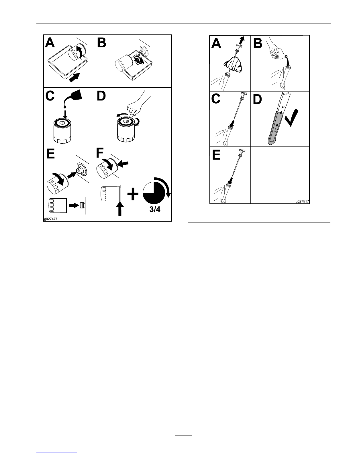
Maintenance
B
A
C D
E
F
3/4
g027477
Figure40
5.ApplyathinlmofcleanExmark4-Cycle
PremiumEngineOiltotherubbergasketonthe
newlter.
Note:Ensuretheoilltergaskettouchesthe
engine,thenanextra3/4turniscompleted.
Note:Disposeoftheusedoilatarecycling
center.
6.Slowlypourapproximately80%ofthespecied
oilintothellertube—useoilrecommendedin
theCheckingtheEngineOil–KohlerEngine
section.
B
A
C
D
E
g027517
Figure41
7.Checktheoillevel;refertoCheckingthe
EngineOil–KohlerEnginesection.
8.Starttheengineandcheckforleaks.
ServicingtheSpark
Plug-Exmark708ccEngine
ServiceInterval:Every100hours/Yearly
(whichevercomesrst)
Every200hours/Every2
years(whichevercomes
rst)—Replacethespark
plug(Exmark708cc
engine).
Ensurethattheairgapbetweenthecenterandside
electrodesiscorrectbeforeinstallingthesparkplug.
Useasparkplugwrenchforremovingandinstalling
thesparkplugandagappingtoolorfeelergaugeto
checkandadjusttheairgap.Installanewsparkplug
ifnecessary.
Type:ChampionRN9YCorequivalent
AirGap:0.030inch(.76mm)
45
Page 46

Maintenance
RemovingtheSparkPlug-Exmark
708ccengine
1.DisengagethePTOandensuretheparkingbrake
isengaged.
2.Stoptheengine,removethekey,andwaitforall
movingpartstostopbeforeleavingtheoperating
position.
3.Disconnectthewirefromthesparkplug.
B
A
g027478
Figure42
Note:Duetothedeeprecessaroundthespark
plug,blowingoutthecavitywithcompressedair
isusuallythemosteffectivemethodforcleaning.
Thesparkplugismostaccessiblewhentheblower
housingisremovedforcleaning.
CheckingtheSparkPlug–Exmark
708ccEngine
1.Inspectthesparkplug
Note:Ifyouseelightbrownorgrayonthe
insulator,theengineisoperatingproperly .A
blackcoatingontheinsulatorusuallymeansthe
aircleanerisdirty.
Important:DoNotcleanthesparkplug(s).
Alwaysreplacethesparkplug(s)whenithas:
ablackcoating,wornelectrodes,anoilylm,
orcracks.
B
A
g027479
Figure43
1.Centerelectrode
insulator
3.Airgap(nottoscale)
2.Sideelectrode
2.Checkthegapbetweenthecenterandside
electrodes.
3.Setthegapto0.030inch(.76mm).
InstallingtheSparkPlug–Exmark
708ccEngine
1.Installthesparkplug.Makesurethattheairgap
issetcorrectly.
2.Tightenthesparkplugto18.5–22.1ft-lb(25–30
N-m).
B
A
25-30 N-m
18.5-22.1 ft-lb
g027960
C
D
Figure44
3.Pushthewireontothesparkplug.
ServicingtheSpark
Plug-KohlerEngine
ServiceInterval:Every200hours
46
Page 47

Maintenance
Every500hours—Replace
thesparkplug(Kohler
engine).
Ensurethattheairgapbetweenthecenterandside
electrodesiscorrectbeforeinstallingthesparkplug.
Useasparkplugwrenchforremovingandinstalling
thesparkplugandagappingtoolorfeelergaugeto
checkandadjusttheairgap.Installanewsparkplug
ifnecessary.
ThesparkplugisRFIcompliant.Equivalentalternate
brandplugscanalsobeused.
Type:ChampionXC12YCorequivalent
AirGap:0.030inch(.76mm)
RemovingtheSparkPlug–Kohler
engine
1.DisengagethePTOandensuretheparkingbrake
isengaged.
2.Stoptheengine,removethekey,andwaitforall
movingpartstostopbeforeleavingtheoperating
position.
3.Disconnectthewirefromthesparkplug.
B
A
g027478
Figure45
4.Cleanaroundthesparkplugtopreventdirtfrom
fallingintotheengineandpotentiallycausing
damage.
5.Removethesparkplugandmetalwasher.
CheckingtheSparkPlug–Kohler
Engine
1.Inspectthesparkplug
Note:Ifyouseelightbrownorgrayonthe
insulator,theengineisoperatingproperly .A
blackcoatingontheinsulatorusuallymeansthe
aircleanerisdirty.
Important:DoNotcleanthesparkplug.
Alwaysreplacethesparkplugwhenithasa
blackcoating,wornelectrodes,anoilylm,
orcracks.
B
A
g027479
Figure46
1.Centerelectrode
insulator
3.Airgap(nottoscale)
2.Sideelectrode
2.Checkthegapbetweenthecenterandside
electrodes.
3.Setthegapto0.030inch(.76mm).
InstallingtheSparkPlug–Kohler
Engine
1.Installthesparkplug.Makesurethattheairgap
issetcorrectly.
2.Tightenthesparkplugto18to22ft-lb(25to29
N-m).
Figure47
3.Pushthewireontothesparkplug.
47
Page 48

Maintenance
CleaningtheBlowerHousing
ServiceInterval:Every100hours/Yearly
(whichevercomesrst)
Moreoftenunderdirty
conditions.
Toensurepropercooling,makesurethegrassscreen,
coolingns,andotherexternalsurfacesoftheengine
arekeptcleanatalltimes.
1.Removetheblowerhousingandanyothercooling
shrouds.
2.Cleanthecoolingnsandexternalsurfacesas
necessary.
3.Makesurethecoolingshroudsarereinstalled
Important:Operatingtheenginewithablocked
grassscreen,dirtyorpluggedcoolingns,
and/orcoolingshroudsremoved,willcause
enginedamageduetooverheating.
FuelSystemMaintenance
ReplacingtheFuelFilter
ServiceInterval:Every100hours/Yearly
(whichevercomesrst)
DANGER
Incertainconditions,gasolineisextremely
ammableandhighlyexplosive.Areor
explosionfromgasolinecanburnyouandothers
andcandamageproperty.
•Performanyfuelrelatedmaintenancewhen
theengineiscold.Dothisoutdoorsinan
openarea.Wipeupanygasolinethatspills.
•Neversmokewhendraininggasoline,and
stayawayfromanopenameorwherea
sparkmayignitethegasolinefumes.
Neverinstalladirtylterifitisremovedfromthe
fuelline.
1.Parkthemachineonalevelsurfaceanddisengage
thebladecontrolswitch.
2.Ensuretheparkingbrakeisengaged,stopthe
engine,removethekey ,andwaitforallmoving
partstostopbeforeleavingtheoperatingposition.
3.Thefuellterisinthefuellinebetweenthetank
andengine.
4.Squeezetheendsofthehoseclampstogetherand
slidethemawayfromthelter.
Figure48
1.Fuellter-Kohlerengine2.Fuellter-Exmarkengine
5.Removethelterfromthefuellines.
6.Installanewlterwiththeowdirectionarrow
comingfromthefueltankandpointingtothe
engine.Movethehoseclampsclosetothelter
tosecureitinplace.
ServicingtheEmissions
Filter
ServiceInterval:Yearly
Themachineisequippedwithanemissionslter
connectedtoateettingontheventlinecoming
fromthegastank.Thelterhasanopenportby
design.Theltershouldbeinspectedregularly .
Replacethelterifthelterisdirtyorclogged.
48
Page 49

Maintenance
ElectricalSystem
Maintenance
WARNING
CALIFORNIA
Proposition65Warning
Batteryposts,terminals,andrelated
accessoriescontainleadandlead
compounds,chemicalsknowntotheStateof
Californiatocausecancerandreproductive
harm.Washhandsafterhandling.
ChargingtheBattery
RemovingtheBattery
WARNING
Batteryterminalsormetaltoolscouldshort
againstmetalmachinecomponentscausing
sparks.Sparkscancausethebatterygassesto
explode,resultinginpersonalinjury.
•Whenremovingorinstallingthebattery,Do
Notallowthebatteryterminalstotouchany
metalpartsofthemachine.
•DoNotallowmetaltoolstoshortbetween
thebatteryterminalsandmetalpartsofthe
machine.
DANGER
Chargingorjumpstartingthebatterymay
produceexplosivegases.Batterygasescan
explodecausingseriousinjury.
•Keepsparks,ames,orcigarettesawayfrom
battery.
•Ventilatewhenchargingorusingbatteryin
anenclosedspace.
•Makesureventingpathofbatteryisalways
openoncebatteryislledwithacid.
•Alwaysshieldeyesandfacefrombattery.
DANGER
Batteryelectrolytecontainssulfuricacid,which
ispoisonousandcancausesevereburns.
Swallowingelectrolytecanbefatalorifittouches
skincancausesevereburns.
•Wearsafetyglassestoshieldeyes,andrubber
glovestoprotectskinandclothingwhen
handlingelectrolyte.
•DoNotswallowelectrolyte.
•Intheeventofanaccident,ushwithwater
andcalladoctorimmediately .
CAUTION
Iftheignitionisinthe“ON”positionthere
ispotentialforsparksandengagementof
components.Sparkscouldcauseanexplosionor
movingpartscouldaccidentallyengagecausing
personalinjury.
Besureignitionswitchisinthe“OFF”position
beforechargingthebattery.
1.Parkthemachineonalevelsurfaceanddisengage
thebladecontrolswitch.
2.Ensuretheparkingbrakeisengaged,stopthe
engine,removethekey ,andwaitforallmoving
partstostopbeforeleavingtheoperatingposition.
3.Raisetheseat.
4.Disconnectthenegative(black)groundcable
fromthebatterypost(Figure49).Retainall
fasteners.
49
Page 50

Maintenance
Figure49
1.Negativebatterypost4.Positivebatterypost
2.Bolt,washer,andnut5.Batterystrap
3.T erminalboot6.Battery
WARNING
Incorrectbatterycableroutingcoulddamage
themachineandcablescausingsparks.
Sparkscancausethebatterygassesto
explode,resultinginpersonalinjury.
•Alwaysdisconnectthenegative(black)
batterycablebeforedisconnectingthe
positive(red)cable.
•Alwaysconnectthepositive(red)battery
cablebeforeconnectingthenegative
(black)cable.
5.Slidetherubbercoverupthepositive(red)cable.
Disconnectthepositive(red)cablefromthe
batterypost.Retainallfasteners.
6.Removethebatterystrap(Figure49)andliftthe
batteryfromthebatterytray .
CheckingtheBatteryCharge
1.Removethebatteryfromthechassis;referto
RemovingtheBattery.
2.Allowingbatteriestostandforanextended
periodwithoutrechargingthemwillresultin
reducedperformanceandservicelife.T opreserve
optimumbatteryperformanceandlife,recharge
batteriesinstoragewhentheopencircuitvoltage
dropsto12.4volts.
Note:Topreventdamageduetofreezing,
batteryshouldbefullychargedbeforeputting
awayforwinterstorage.
3.Checkthevoltageofthebatterywithadigital
voltmeter.Locatethevoltagereadingofthe
batteryinthetablebelowandchargethebattery
fortherecommendedtimeintervaltobringthe
chargeuptoafullchargeof12.6voltsorgreater.
Important:Makesurethenegativebattery
cableisdisconnectedandthebatterycharger
usedforchargingthebatteryhasanoutputof
16voltsand7ampsorlesstoavoiddamaging
thebattery(seechartbelowforrecommended
chargersettings).
Voltage
Reading
Percent
Charge
Maximum
Charger
Settings
Charging
Interval
12.6or
greater
100%
16volts/7
amps
No
Charging
Required
12.4–12.675–100%
16volts/7
amps
30Minutes
12.2–12.450–75%
16volts/7
amps
1Hour
12.0–12.225–50%
14.4volts/4
amps
2Hours
11.7–12.00–25%
14.4volts/4
amps
3Hours
11.7orless
0%
14.4volts/2
amps
6Hoursor
More
RecommendedJumpStarting
Procedure
1.Checktheweakbatteryforterminalcorrosion
(white,green,orblue“snow”),itmustbecleaned
offpriortojumpstarting.Cleanandtighten
connectionsasnecessary.
CAUTION
Corrosionorlooseconnectionscancause
unwantedelectricalvoltagespikesatanytime
duringthejumpstartingprocedure.
DoNotattempttojumpstartwithlooseor
corrodedbatteryterminalsordamagetothe
enginemayoccur.
50
Page 51
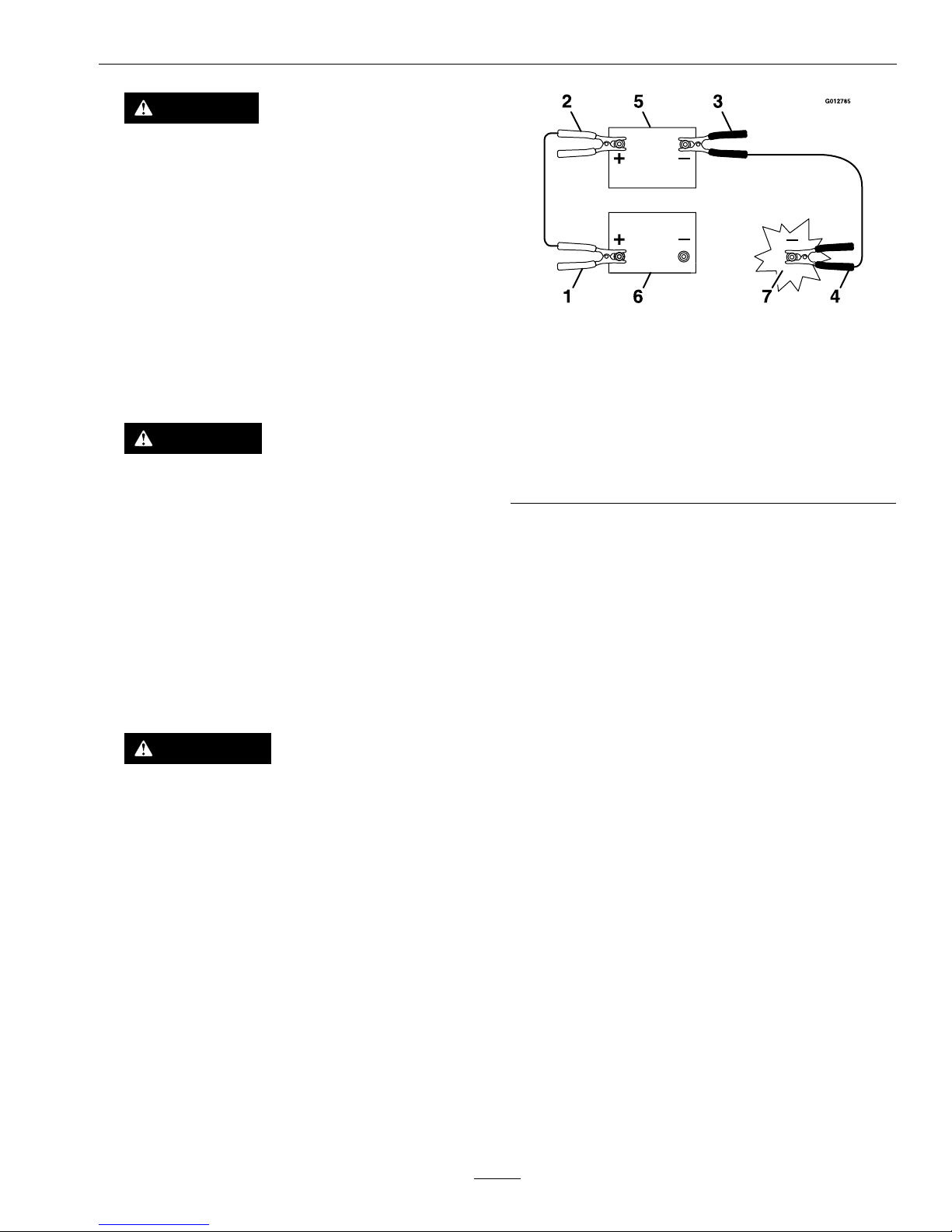
Maintenance
DANGER
Jumpstartingaweakbatterythatiscracked,
frozen,haslowelectrolytelevel,oran
open/shortedbatterycell,cancausean
explosionresultinginseriouspersonalinjury.
DoNotjumpstartaweakbatteryifthese
conditionsexist.
2.Makesuretheboosterisagoodandfullycharged
leadacidbatteryat12.6voltsorgreater.Use
properlysizedjumpercables(4to6AWG)with
shortlengthstoreducevoltagedropbetween
systems.Makesurethecablesarecolorcodedor
labeledforthecorrectpolarity.
CAUTION
Connectingthejumpercablesincorrectly
(wrongpolarity)canimmediatelydamagethe
electricalsystem.
Becertainofbatteryterminalpolarityand
jumpercablepolaritywhenhookingup
batteries.
Note:Thefollowinginstructionsareadapted
fromtheSAEJ1494Rev .Dec.2001–Battery
BoosterCables–SurfaceVehicleRecommended
Practice(SAE–SocietyofAutomotive
Engineers).
WARNING
Batteriescontainacidandproduceexplosive
gases.
•Shieldtheeyesandfacefromthebatteries
atalltimes.
•DoNotleanoverthebatteries.
Note:Besuretheventcapsaretightandlevel.
Placeadampcloth,ifavailable,overanyvent
capsonbothbatteries.Besurethevehiclesdo
nottouchandthatbothelectricalsystemsare
offandatthesameratedsystemvoltage.These
instructionsarefornegativegroundsystemsonly.
3.Connectthepositive(+)cabletothepositive(+)
terminalofthedischargedbatterythatiswiredto
thestarterorsolenoidasshowninFigure50.
Figure50
1.Positive(+)cableondischargedbattery
2.Positive(+)cableonboosterbattery
3.Negative(–)cableontheboosterbattery
4.Negative(–)cableontheengineblock
5.Boosterbattery
6.Dischargedbattery
7.Engineblock
4.Connecttheotherendofthepositivecabletothe
positiveterminaloftheboosterbattery.
5.Connecttheblacknegative(–)cabletotheother
terminal(negative)oftheboosterbattery.
6.MAKETHEFINALCONNECTIONON
THEENGINEBLOCKOFTHESTALLED
VEHICLE(NOTTOTHENEGATIVEPOST)
AWAYFROMTHEBATTERY .STANDBACK.
7.Startthevehicleandremovethecablesinthe
reverseorderofconnection(theengineblock
(black)connectionisthersttodisconnect).
InstallingtheBattery
1.Positionthebatteryinthetraywiththeterminal
poststowardtheoperatingposition(Figure49).
2.Installthepositive(red)batterycabletothe
positive(+)batteryterminalusingthefasteners
removedpreviously.
3.Installthenegativebatterycabletothenegative
(-)batteryterminalusingthefastenersremoved
previously.
4.Slidetheredterminalbootontothepositive(red)
batterypost.
5.Securethebatterywiththestrap(Figure49).
51
Page 52

Maintenance
ServicingtheFuses
ServiceInterval:Asrequired
Theelectricalsystemisprotectedbyfuses.Itrequires
nomaintenance;however,ifafuseblows,checkthe
component/circuitforamalfunctionorshort.
Fuse:
•MainF1-30amp,blade-type
•ChargeCircuitF2-25amp,blade-type
1.Removethefourscrewssecuringthecontrol
paneltothemachine.Retainallfasteners
2.Liftthecontrolpaneuptoaccessthemainwiring
harnessandfuseblock(Figure51).
3.T oreplaceafuse,pulloutonthefusetoremove
it(Figure51).
30
25
30
25
G014921
2
1
Figure51
1.Main-30amp
2.Chargecircuit-25amp
4.Returnthecontrolpaneltoitsoriginalposition.
Usethefourscrewsremovedpreviouslytosecure
thepaneltothemachine.
DriveSystemMaintenance
CheckingtheTirePressure
ServiceInterval:Every25hours/Monthly
(whichevercomesrst)
Maintaintheairpressureinthefrontandreartiresas
specied.Uneventirepressurecancauseunevencut.
Checkthepressureatthevalvestem(Figure52).
Checkthetireswhentheyarecoldtogetthemost
accuratepressurereading.
RearTires:13psi(90kPa)
FrontTires(casterwheels):13psi(90kPa)
Figure52
1.Valvestem
ReleasingtheElectricBrake
ServiceInterval:Asrequired
Theelectricbrakecanbereleasebymanuallyrotating
thelinkarmsforward.Oncetheelectricbrakeis
energizedthebrakewillreset.
Toreleasethebrake:
Figure53
1.Rotatebrake-link
armforwardonthe
electric-brake-control
module
2.Leftreartire
1.Turntheignitionkeytothe“OFF”positionor
disconnectthebattery
2.Locatetheshaftswherethebrakelinkarmsare
connectedonbothsidesoftheelectricbrake.
3.Rotatetheshaftforwardtoreleasethebrake.
CheckingtheHydraulicOil
Level–50InchOnly
ServiceInterval:Every25hours
52
Page 53

Maintenance
Checkexpansionreservoirandifnecessaryadd
ExmarkPremiumHydroOiltotheFULLCOLD
line.
Figure54
1.Expansionreservoir3.Engine
2.FullColdline
ChangingtheHydraulic
SystemFilterandOil––50
InchOnly
ServiceInterval:Aftertherst50hours
Every400hoursthereafter.
Thelterandoilarechangedatthesametime.Do
Notreuseoil.Oncethenewlterisinstalledandoil
isaddedanyairinthesystemmustbepurged.
Thebleedingprocessisrepeateduntiltheoilremains
attheFULLCOLDlineinthereservoirafterpurging.
Failuretoproperlyperformthisprocedurecan
resultinirreparabledamagetothetransaxle
drivesystem.
RemovingHydraulicSystemFilters
1.Stopengine,waitforallmovingpartstostop,and
allowenginetocool.Removethekeyandengage
theparkingbrake.
2.Raisetherearofmachineupandsupportwith
jackstands(orequivalentsupport)justhigh
enoughtoallowdrivewheelstoturnfreely.
Figure55
1.Jackingpoints
3.Locatethelterandlterguardsoneachtransaxle
drivesystem.Removethreescrewssecuringthe
lterguardandguard.
Figure56
Rightsideshown
1.Transaxledrive
4.Screws
2.Oillter
5.Ventplug
3.Filterguard
4.Carefullycleanareaaroundlters.Itisimportant
thatnodirtorcontaminationenterhydraulic
system.
5.Placeacontainerbelowtheltertocatchthe
oilthatdrainswhenthelterandventplugsare
removed.
53
Page 54

Maintenance
6.Locateandremovetheventplugoneach
transmission
7.Unscrewtheltertoremoveandallowoilto
drainfromdrivesystem.
Repeatthisprocedureforbothlters.
InstallingtheHydraulicSystem
Filters
G008748
3/4
1
2
3
4
5
6
Figure57
1.Applyathincoatofoilonthesurfaceofthe
rubbersealofeachlter.
2.Turnthelterclockwiseuntilrubbersealcontacts
thelteradapterthentightenthelteran
additional3/4to1fullturn.Repeatfortheother
lter
3.Installthelterguardsovereachlteras
previouslyremoved.Usethethreescrewsto
securethelterguards.
4.V erifytheventplugsareremovedbeforeadding
theoil.
5.Slowlypourthespeciedoilthroughexpansion
reservoiruntiloilcomesoutofoneofthevent
plugholes.Stopandinstallthatventplug.Torque
theplugto180in-lb(20.3N-m).
6.Continuetoaddoilthroughtheexpansion
reservoiruntiloilcomesoutoftheremaining
ventplugholeonthesecondtransmission.Stop
andinstallthatventplug.Torquetheplugto180
in-lb(20.3N-m).
7.Continuetoaddoilthroughtheexpansion
reservoiruntilitreachestheFULLCOLDlineon
theexpansionreservoir.
8.Installthetransaxleguard.
9.ProceedtotheBleedingtheHydraulicSystem
section.
Important:Failuretoperformthe
Bleeding
the Hy draulic System
procedureafter
changinghydraulicltersandoilcanresult
inirreparabledamagetothetransaxledrive
system.
BleedingtheHydraulicSystem
1.Entertheoperator'sposition.Startengineand
movethrottlecontrolaheadto1/2throttle
position.Disengageparkingbrake.
A.Movethebypassleversintothepushing
themachineposition;refertoPushingthe
MachinebyHandsectioninOperation.
Withthebypassvalvesopenandtheengine
running,slowlymovethetraction-control
pedalinbothforwardandreverse(5or6
times).
B.Movethebypassleversintotheoperating
themachineposition.Withthebypassvalve
closedandtheenginerunning,slowlymove
thetraction-controlpedalinbothforwardand
reversedirections(5to6times).
C.Stoptheengineandchecktheoillevelinthe
expansionreservoir.Addthespeciedoil
asuntilitreachestheFullColdlineonthe
expansionreservoir.
2.Repeatstep1untilalltheairiscompletelypurged
fromthesystem.
Whenthetransaxleoperatesatnormalnoise
levelsandmovessmoothlyforwardandreverseat
normalspeeds,thenthetransaxleisconsidered
purged.
3.Checktheoillevelintheexpansionreservoirone
lasttime.Addthespeciedoiluntilitreaches
54
Page 55

Maintenance
theFullColdlineontheexpansionreservoirif
necessary.
MowerMaintenance
ServicingtheCuttingBlades
Maintainsharpbladesthroughoutthecuttingseason
becausesharpbladescutcleanlywithouttearingor
shreddingthegrassblades.Tearingandshredding
turnsgrassbrownattheedges,whichslowsgrowth
andincreasesthechanceofdisease.
Checkthecutterbladesdailyforsharpness,andfor
anywearordamage.Filedownanynicksandsharpen
thebladesasnecessary.Ifabladeisdamagedor
worn,replaceitimmediatelywithagenuineExmark
replacementblade.Forconvenientsharpeningand
replacement,youmaywanttokeepextrabladeson
hand.
WARNING
Awornordamagedbladecanbreak,andapiece
ofthebladecouldbethrownintotheoperator's
orbystander'sarea,resultinginseriouspersonal
injuryordeath.
•Inspectthebladeperiodicallyforwearor
damage.
•Replaceawornordamagedblade.
BeforeInspectingorServicingthe
Blades
Parkthemachineonalevelsurface,disengagethe
bladecontrolswitch,andensuretheparkingbrakeis
engaged.Stoptheengineandremovethekey.
InspectingtheBlades
ServiceInterval:Beforeeachuseor
daily—Checkthecutting
blades.
1.Inspectthecuttingedges(Figure58).Iftheedges
arenotsharporhavenicks,removeandsharpen
theblades;refertoSharpeningtheBlades.
2.Inspecttheblades,especiallythecurvedarea
(Figure58).Ifyounoticeanydamage,wear,
oraslotforminginthisarea(items3and4in
Figure58),immediatelyinstallanewblade.
Figure58
1.Cuttingedge3.Wear/slotforming
2.Curvedarea
4.Damage
CheckingforBentBlades
Note:Themachinemustbeonalevelsurfacefor
thefollowingprocedure.
1.Raisethemowerdecktothehighestheight-of-cut
position;alsoconsideredthe'transport'position.
2.Whilewearingthicklypaddedglovesorother
adequatehandprotectionslowlyrotatebladeto
bemeasuredintoapositionthatallowseffective
measurementofthedistancebetweenthecutting
edgeandthelevelsurfacethemachineison.
G014972
1
2
3
Figure59
1.Deck3.Blade
2.Spindlehousing
55
Page 56
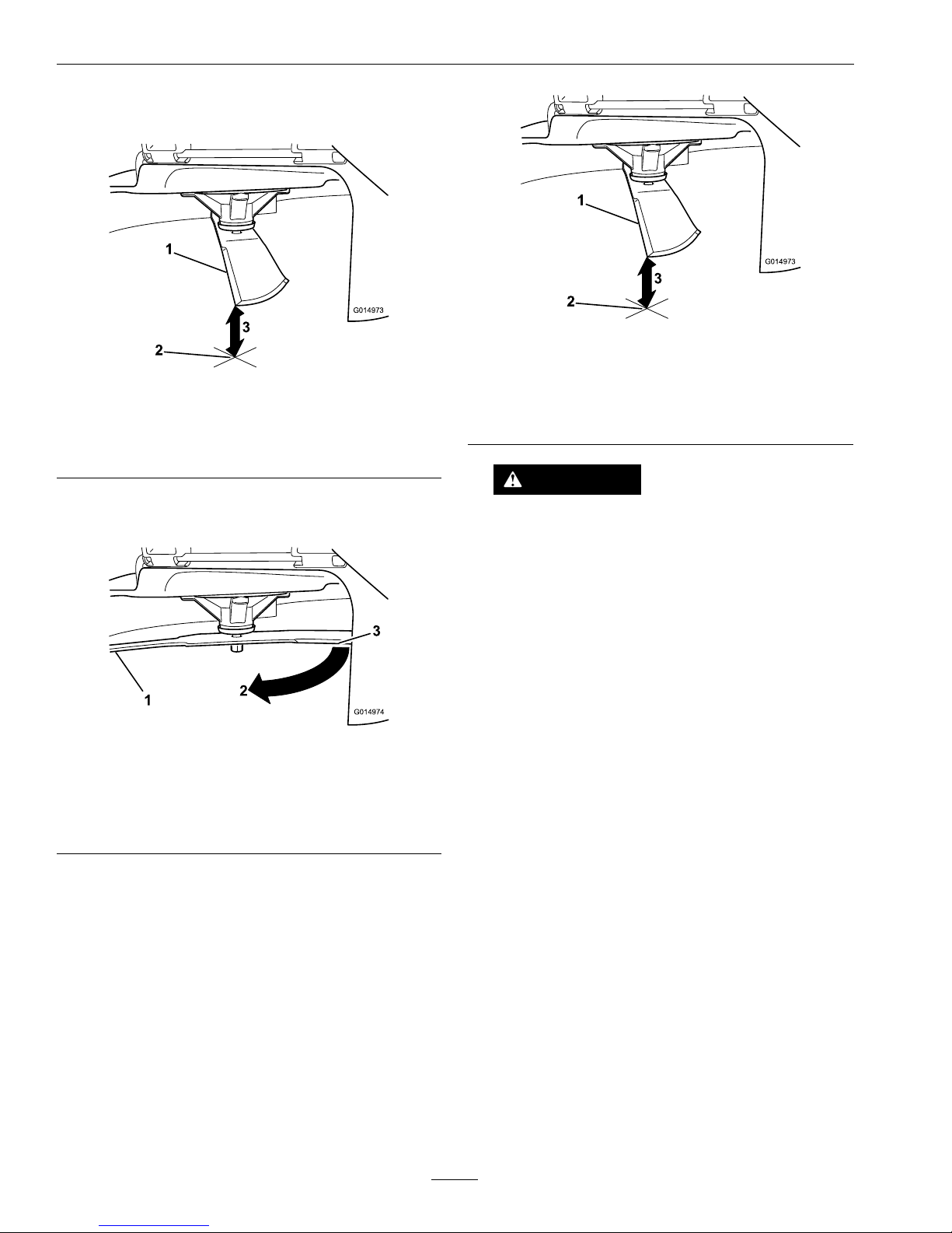
Maintenance
3.Measurefromthetipofthebladetotheat
surfacehere.
G014973
1
2
3
Figure60
1.Blade,inpositionformeasuring
2.Levelsurface
3.Measureddistancebetweenbladeandsurface(A)
4.Rotatethesameblade180degreessothatthe
opposingcuttingedgeisnowinthesameposition.
G014974
1
2
3
Figure61
1.Blade,sidepreviouslymeasured
2.Measurementpositionusedpreviously
3.Opposingsideofbladebeingmovedintomeasurement
position
5.Measurefromthetipofthebladetotheat
surfacehere.Thevarianceshouldbenomore
than1/8inch(3mm).
G014973
1
2
3
Figure62
1.Opposingbladeedge,inpositionformeasuring
2.Levelsurface
3.Secondmeasureddistancebetweenbladeandsurface
(B)
WARNING
Abladethatisbentordamagedcouldbreak
apartandcouldseriouslyinjureorkillyouor
bystanders.
•Alwaysreplacebentordamagedblade
withanewblade.
•Neverleorcreatesharpnotchesinthe
edgesorsurfacesofblade.
A.IfthedifferencebetweenAandBisgreater
than1/8inch(3mm)replacethebladewitha
newblade.RefertoRemovingtheBladesand
InstallingtheBlades.
Note:Ifabentbladeisreplacedwithanew
oneandthedimensionobtainedcontinues
toexceed1/8inch(3mm),thebladespindle
couldbebent.ContactanAuthorizedExmark
Dealerforservice.
B.Ifthevarianceiswithinconstraints,moveto
thenextblade..
Repeatthisprocedureoneachblade.
RemovingtheBlades
Thebladesmustbereplacedifasolidobjectishit,if
thebladeisoutofbalance,orthebladeisbent.To
ensureoptimumperformanceandcontinuedsafety
conformanceofthemachine,usegenuineExmark
replacementblades.Replacementbladesmadeby
othermanufacturersmayresultinnon-conformance
withsafetystandards.
56
Page 57

Maintenance
Holdthebladeendusingaragorthickly-padded
glove.Removethebladebolt,curvedwasher,and
bladefromthespindleshaft(Figure63).
G027833
Figure63
1.Sailareaofblade3.Curvedwasher
2.Blade4.Bladebolt
SharpeningtheBlades
1.Usealetosharpenthecuttingedgeatbothends
oftheblade(Figure64).Maintaintheoriginal
angle.Thebladeretainsitsbalanceifthesame
amountofmaterialisremovedfrombothcutting
edges.
Figure64
1.Sharpenatoriginalangle
2.Checkthebalanceofthebladebyputtingitona
bladebalancer(Figure65).Ifthebladestaysina
horizontalposition,thebladeisbalancedandcan
beused.Ifthebladeisnotbalanced,lesome
metalofftheendofthesailareaonly(Figure64).
Repeatthisprocedureuntilthebladeisbalanced.
Figure65
1.Blade2.Balancer
InstallingtheBlades
1.Installthebladeontothespindleshaft(Figure63).
Important:Thecurvedpartoftheblade
mustbepointingupwardtowardtheinsideof
themowertoensurepropercutting.
2.Installthecurvedwasher(cuppedsidetowardthe
blade)andthebladebolt(Figure63).
3.T orquethebladeboltto35-65ft-lb(47-88N-m).
LevelingtheMowerDeck
Checktoensurethemowerdeckislevelanytime
youinstallthemowerorwhenyouseeanunevencut
onyourlawn.
Themowerdeckmustbecheckedforbentblades
priortoleveling;anybentbladesmustberemoved
andreplaced.RefertotheCheckingforBent
Bladesprocedurebeforecontinuing.
Themowerdeckmustbeleveledside-to-siderst
thenthefronttorearslopecanbeadjusted.
Requirements:
•Themachinemustbeonalevelsurface.
•Allfourtiresmustbeproperlyinated.Referto
CheckingtheTirePressureintheDriveSystem
Maintenancesection.
Side-to-SideLeveling
1.Parkthemachineonalevelsurfaceanddisengage
thebladecontrolswitch.
2.Ensuretheparkingbrakeisengaged,stopthe
engine,removethekey ,andwaitforallmoving
partstostopbeforeleavingtheoperatingposition.
3.Settheheight-of-cutlevertomiddleposition.
4.Carefullyrotatethebladessothattheyareallside
toside(Figure66andFigure67).
57
Page 58

Maintenance
G009682
1
2
2
3
3
4
4
Figure66
MowerDeckwith2Blades
1.Bladessidetoside
3.Outsidecuttingedges
2.Sailareaofblade4.Measurefromthetip
ofthebladetotheat
surfacehere
G005278
1
2
2
3
3
4
4
Figure67
MowerDeckwith3Blades
1.Bladessidetoside
3.Outsidecuttingedges
2.Sailareaofblade4.Measurefromthetip
ofthebladetotheat
surfacehere
5.Measurebetweentheoutsidecuttingedgesand
theatsurface(Figure66andFigure67).Ifboth
measurementsarenotwithin3/16inch(5mm),
anadjustmentisrequired;continuewiththis
procedure.
6.Supporttheweightofmowerdeckbyplacing
woodblocksundertheedgesofthedeck.
Note:Avoidplacingthesupportsunderany
anti-scalprollersifpresentonthedeck.
7.Movetotheleftsideofthemachine.
8.Loosentheside-lockingnut.
9.Raiseorlowertheleftsideofthemowerdeckby
rotatingtherearnut.(Figure68).
Note:Rotatetherearnutclockwisetoraisethe
mowerdeck;rotatetherearnutcounter-clockwise
tolowerthemowerdeck.
Figure68
1.Hangerbracket3.Rear-lockingnut
2.Side-lockingnut
10.Checktheside-to-sideadjustmentsagain.Repeat
thisprocedureuntilthemeasurementsarecorrect.
11.Continuelevelingthedeckbycheckingthe
front-to-rearbladeslope;refertoAdjustingthe
Front-to-RearBladeSlope.
AdjustingtheFront-to-RearBlade
Slope
Checkthefront-to-rearbladelevelanytimeyouinstall
themower.Ifthefrontofthemowerismorethan
5/16inch(7.9mm)lowerthantherearofthemower,
adjustthebladelevelusingthefollowinginstructions:
1.Parkthemachineonalevelsurfaceanddisengage
thebladecontrolswitch.
2.Ensuretheparkingbrakeisengaged,stopthe
engine,removethekey ,andwaitforallmoving
partstostopbeforeleavingtheoperatingposition.
3.Settheheight-of-cutlevertomiddleposition.
Note:Checkandadjusttheside-to-sideblade
levelifyouhavenotcheckedthesetting;referto
Side-to-SideLeveling.
4.Carefullyrotatethebladessotheyarefacingfront
torear(Figure69andFigure70).
58
Page 59

Maintenance
G009658
1
2
2
Figure69
MowerDeckwith2Blades
1.Bladesfronttorear
2.Measurefromthetipofthebladetotheatsurfacehere
G009659
1
2
3
2
3
Figure70
MowerDeckwith3Blades
1.Bladesfronttorear
2.Outsidecuttingedges
3.Measurefromthetipofthebladetotheatsurfacehere
5.Measurefromthetipofthefrontbladetotheat
surfaceandthetipoftherearbladetotheat
surface(Figure69andFigure70).Ifthefront
bladetipisnot1/16-5/16inch(1.6-7.9mm)lower
thantherearbladetip,adjustthefrontlocknut.
6.T oadjustthefront-to-rearbladeslope,rotate
theadjustmentnutinthefrontofthemower
(Figure71).
G014634
1
2
3
Figure71
1.Adjustingrod3.Locknut
2.Adjustingblock
7.T oraisethefrontofthemower,tightenthe
adjustmentnut.Tolowerthefrontofthemower,
loosentheadjustmentnut.
8.Afteradjustment,checkthefront-to-rearslope
again.Continueadjustingthenutuntilthefront
bladetipis1/16-5/16inch(1.6-7.9mm)lower
thantherearbladetip(Figure69andFigure70).
9.Whenthefront-to-rearbladeslopeiscorrect
checktheside-to-sidelevelofthemoweragain;
refertoSide-to-SideLeveling.
RemovingtheMower
ServiceInterval:Asrequired
1.Parkthemachineonalevelsurfaceanddisengage
thebladecontrolswitch.
2.Ensuretheparkingbrakeisengaged,stopthe
engine,removethekey ,andwaitforallmoving
partstostopbeforeleavingtheoperatingposition.
3.Lowertheheight-of-cutlevertothelowest
position.
4.Removethehairpincotterfromthefrontsupport
rodandremovetherodfromthedeckbracket
(Figure72).Carefullylowerthefrontofthe
mowerdecktotheground.
59
Page 60

Maintenance
G014635
1
2
3
Figure72
1.Frontsupportrod3.Deckbracket
2.Lockingnut
5.Removeandretainthecotterpinanddeck
retentionlinkfromtheeachhangerbracket(see
Figure73).
Figure73
1.Hangerbracket
3.Cotterpin
2.Deckretentionlink
6.Liftthemowerdeckandhangerbracketsclearof
therearliftrodandlowerthemowercarefullyto
theground(Figure74).
2
2
3
G005077
1
2
2
3
Figure74
1.Mowerdeck
3.Rearliftrod
2.Hangerbracket
7.Slidethemowerdeckrearwardtoremovethe
mowerbeltfromtheenginepulley.
8.Slidethemowerdeckoutfromunderneaththe
machine.
Note:Retainallpartsforfutureinstallation.
MowerBeltMaintenance
InspectingtheBelts
ServiceInterval:Every25hours/Monthly
(whichevercomesrst)
Checkthebeltsforcracks,frayededges,burnmarks,
oranyotherdamage.Replacedamagedbelts.
ReplacingtheMowerBelt
Squealingwhenthebeltisrotating,bladesslipping
whencuttinggrass,frayedbeltedges,burnmarks,
andcracksaresignsofawornmowerbelt.Replace
themowerbeltifanyoftheseconditionsareevident.
1.Parkthemachineonalevelsurfaceanddisengage
thebladecontrolswitch.
2.Ensuretheparkingbrakeisengaged,stopthe
engine,removethekey ,andwaitforallmoving
partstostopbeforeleavingtheoperatingposition.
3.Settheheight-of-cutatthelowestcuttingposition
[1-1/2inch(38mm)].
60
Page 61

Maintenance
4.Usingaspringremovaltool,(P/N.92-5771),
removetheidlerspringfromthedeckhookto
removetensionontheidlerpulleyandrollthe
beltoffofthepulleys(Figure75andFigure76).
WARNING
Thespringisundertensionwheninstalled
andcancausepersonalinjury.
Becarefulwhenremovingthebelt.
G014930
1
2
3
3
4
5
1
2
3
3
4
5
6
4
Figure75
42InchDecks
1.Idlerpulley
4.Spring
2.Mowerbelt5.Enginepulley
3.Outsidepulley6.Springremovaltool
G014931
1
2
3
3
4
5
6
Figure76
50InchDecks
1.Idlerpulley
4.Spring
2.Mowerbelt5.Enginepulley
3.Outsidepulley6.Springremovaltool
5.Routethenewbeltaroundtheenginepulleyand
mowerpulleys(Figure76).
6.Usingaspringremovaltool,(P/N92-5771),
installtheidlerspringoverthedeckhookand
placingtensionontheidlerpulleyandmowerbelt
(Figure75andFigure76).
InstallingtheMower
ServiceInterval:Asrequired
1.Parkthemachineonalevelsurfaceanddisengage
thebladecontrolswitch.
2.Ensuretheparkingbrakeisengaged,stopthe
engine,removethekey ,andwaitforallmoving
partstostopbeforeleavingtheoperatingposition.
3.Slidethemowerunderthemachine.
4.Lowertheheight-of-cutlevertothelowest
position.
5.Lifttherearofthemowerdeckandguidethe
hangerbracketsovertherearliftrod(Figure74).
6.Attachthefrontsupportrodtothemowerdeck
withtheclevispinandhairpincotter(Figure72).
7.Installthemowerbeltontotheenginepulley;
refertoReplacingtheMowerBelt.
61
Page 62

Maintenance
ReplacingtheDischarge
Deector
DANGER
Anuncovereddischargeopeningcouldallowthe
lawnmowertothrowobjectsintheoperator’sor
bystander’sdirectionandresultinseriousinjury.
Also,contactwiththebladecouldoccur.
Neveroperatethelawnmowerunlessyouinstall
amulchplate,dischargedeector,orgrass
collectionsystem.
Inspectthedischargedeectorfordamagebefore
eachuse.Replaceanydamagedpartsbeforeuse.
1.Disengagethespringfromthenotchinthe
deectorbracketandslidetherodoutofthe
weldeddeckbrackets,spring,anddischarge
deector(Figure77).Removethedamagedor
worndischargedeector.
g017617
1
3
2
4
5
Figure77
1.Rod4.Deckbrackets
2.Spring5.Springinstalledoverthe
rod
3.Deectorassembly
2.Positionthenewdischargedeectorassembly
withthebracketendsbetweentheweldedbrackets
onthedeckasshowninFigure77.
3.Installthespringontothestraightendoftherod.
Positionthespringontherodasshowninso
theshorterspringendiscomingfromunderthe
rodbeforethebendandgoingovertherodasit
returnsfromthebend.
4.Lifttheloopendofthespringandplaceitinto
thenotchonthedeectorassemblybracket
(Figure78).
62
Page 63

Maintenance
g017618
1
3
4
2
Figure78
1.Rodandspring
assemblyinstalled
3.Rod,shortend,moved
behindmowerbracket
2.Loopendofthespring
installedintothenotchin
thedeectorbracket
4.Shortend,retainedby
mowerbracket.
5.Securetherodandspringassemblybytwistingit
sotheshortendoftherodcanbeplacedbehind
thefrontbracketweldedtothedeck(Figure78).
Important:Thegrassdeectormustbe
springloadedinthedownposition.Liftthe
deectoruptotestthatitsnapstothefull
downposition.
Cleaning
CleanGrassBuild-UpUnder
Deck
ServiceInterval:Beforeeachuseordaily
1.Stopengine,waitforallmovingpartstostop,and
removekey.Engageparkingbrake.
2.Raisedecktothetransport(41/2inch(114mm)
cuttingheight)position.Liftthefrontofunit
andsupportunitusingjackstandsorequivalent
support.
CAUTION
Raisingthemowerdeckforserviceor
maintenancerelyingsolelyonmechanical
orhydraulicjackscouldbedangerous.The
mechanicalorhydraulicjacksmaynotbe
enoughsupportormaymalfunctionallowing
theunittofall,whichcouldcauseinjury.
DoNotrelysolelyonmechanicalorhydraulic
jacksforsupport.Useadequatejackstands
orequivalentsupport.
3.Cleanoutanygrassbuild-upfromundersideof
deckandindischargedeector.
CleanEngineandExhaust
SystemArea
ServiceInterval:Beforeeachuseordaily
(Mayberequiredmore
oftenindryordirty
conditions.)
CAUTION
Excessivedebrisaroundenginecoolingair
intakeandexhaustsystemareacancauseengine,
exhaustarea,andhydraulicsystemtooverheat
whichcancreatearehazard.
Cleanalldebrisfromengineandexhaustsystem
area.
1.Stopengine,waitforallmovingpartstostop,and
removekey.Engageparkingbrake.
63
Page 64

Maintenance
2.Cleanalldebrisfromrotatingengineairintake
screen,aroundengineshrouding,andexhaust
systemarea.
3.Wipeupanyexcessivegreaseoroilaroundthe
engineandexhaustsystemarea.
CleanDebrisFromMachine
ServiceInterval:Beforeeachuseordaily
1.Stopengine,waitforallmovingpartstostop,and
removekey.Engageparkingbrake.
2.Cleanoffanyoil,debris,orgrassbuild-uponthe
machineandcuttingdeck,especiallyunderdeck
beltshields,aroundthefueltank,aroundengine
andexhaustarea.
64
Page 65

Storage
Storage
CleaningandStorage
1.Disengagethebladecontrolswitch,releasethe
traction-controlpedaltoplacethemachinein
neutral,engagetheparkingbrake,stoptheengine,
andremovethekey.
2.Removegrassclippings,dirt,andgrimefromthe
externalpartsoftheentiremachine,especiallythe
engine.Cleandirtandchafffromtheoutsideof
theenginecylinderheadnsandblowerhousing.
Important:Youcanwashthemachinewith
milddetergentandwater.Donotpressure
washthemachine.Avoidexcessiveuseof
water,especiallynearthecontrolpanel,under
theseat,aroundtheengine,hydraulicpumps,
andmotors.
3.Servicetheaircleaner;refertoServicingtheAir
CleanerintheEngineMaintenancesection.
4.Greaseandoilthemachine;refertothe
Lubricationsection.
5.Changethecrankcaseoilandlter;refer
toServicingtheEngineOilintheEngine
Maintenancesection.
6.Checkthetirepressure;refertoCheckingthe
TirePressureintheDriveSystemMaintenance
section.
7.Chargethebattery;refertoServicingtheBattery
intheElectricalSystemMaintenancesection.
8.Checktheconditionoftheblades;referto
ServicingtheCuttingBladesintheMower
Maintenancesection.
9.Preparethemachineforstoragewhennon-use
occursover30days.Preparethemachinefor
storageasfollows.
10.Addapetroleumbasedstabilizer/conditioner
tothefuelinthetank.Followthemixing
instructionsfromthestabilizermanufacturer.Do
notuseanalcoholbasedstabilizer(ethanolor
methanol).
Note:Afuelstabilizer/conditionerismost
effectivewhenmixedwithfreshgasolineandused
atalltimes.
Runtheenginetodistributetheconditionedfuel
throughthefuelsystem(5minutes).
Stoptheengine,allowittocool,anddrainthe
fueltank;refertoDrainingtheFuelTankinthe
FuelSystemMaintenancesection.
Restarttheengineandrunituntilitstops.
Choketheengine(ifapplicable).Startandrunthe
engineuntilitwillnotstart.
Disposeoffuelproperly.Recyclepursuantto
localcodes.
Important:Donotstore
stabilizer/conditionedgasolineover
30days.
11.Removethesparkplug(s)andcheckitscondition;
refertoServicingtheSparkPlugintheEngine
Maintenancesection.Withthesparkplug(s)
removedfromtheengine,pourtwotablespoons
ofengineoilintothesparkplughole.Usethe
startertocranktheengineanddistributetheoil
insidethecylinder.Installthesparkplug(s).Do
notinstallthewireonthesparkplug(s).
12.Cleananydirtandchafffromthetopofthe
mower.
13.Scrapeanyheavybuildupofgrassanddirtfrom
theundersideofthemower,thenwashthemower
withagardenhose.
14.Checktheconditionofthedriveandmowerbelts.
15.Checkandtightenallbolts,nuts,andscrews.
Repairorreplaceanypartthatiswornor
damaged.
16.Paintallscratchedorbaremetalsurfaces.Paintis
availablefromyourAuthorizedServiceDealer.
17.Storethemachineinaclean,drygarageorstorage
area.Removethekeyfromtheignitionswitchand
keepitinamemorableplace.Coverthemachine
toprotectitandkeepitclean.
65
Page 66

Troubleshooting
Troubleshooting
Important:Itisessentialthatalloperatorsafetymechanismsbeconnectedandinproperoperating
conditionpriortomoweruse.
Whenaproblemoccurs,DoNotoverlookthesimplecauses.Forexample:startingproblemscouldbe
causedbyanemptyfueltank.
Thefollowingtablelistssomeofthecommoncausesoftrouble.DoNotattempttoserviceorreplacemajor
itemsoranyitemsthatcallforspecialtimingofadjustmentsprocedures(suchasvalves,governor,etc.).Have
thisworkdonebyyourEngineServiceDealer.
Note:WhendisconnectingelectricalconnectorsDONotpullonthewirestoseparatetheconnectors.
ProblemPossibleCauseCorrectiveAction
1.Theengineloadisexcessive.1.Reducegroundspeed.
2.Theoillevelinthecrankcaseislow .
2.Addoiltothecrankcase.
3.Thecoolingnsandairpassagesunder
theengineblowerhousingareplugged.
3.Removetheobstructionfromthecooling
nsandairpassages.
4.Theaircleanerisdirty.
4.Cleanorreplacetheaircleanerelement.
Theengineoverheats.
5.Dirt,water,orstalefuelisinfuelsystem.
5.ContactanAuthorizedServiceDealer.
1.Thebladecontrolswitchisengaged.1.Movethebladecontrolswitchto
Disengaged.
2.Theoperatorisnotseated.
2.Sitontheseat.
3.Batterydoesnothaveafullcharge.
3.
Chargethebattery.SeeCheckBattery
ChargeandRecommendedJump
StartingProceduresectionsin
Maintenance.
4.Theelectricalconnectionsarecorroded
orloose.
4.Checktheelectricalconnectionsforgood
contact.
5.Afuseisblown.
5.Replacethefuse.
Thestarterdoesnotcrank
6.Arelayorswitchisdamaged.6.ContactanAuthorizedServiceDealer.
1.Fueltankisempty .1.Fillthefueltank.
2.Thechokeisnoton.
2.MovethechokelevertoOn(ifapplicable).
3.Theaircleanerisdirty.
3.Cleanorreplacetheaircleanerelement.
4.Thesparkplugwire(s)islooseor
disconnected.
4.Installthewire(s)onthesparkplug.
5.Thesparkplug(s)ispitted,fouled,orthe
gapisincorrect.
5.Installanew ,correctlygappedspark
plug(s).
6.Thereisdirtinfuellter.6.Replacethefuellter.
7.Dirt,water,orstalefuelisinthefuel
system.
7.ContactanAuthorizedServiceDealer.
8.Thereisincorrectfuelinthefueltank.
8.Drainthetankandreplacethefuelwith
thepropertype.
Enginewillnotstart,startshard,orfailsto
keeprunning
9.Theoillevelinthecrankcaseislow .
9.Addoiltothecrankcase.
66
Page 67

Troubleshooting
ProblemPossibleCauseCorrectiveAction
1.Engineloadisexcessive.1.Reducethegroundspeed.
2.Aircleanerisdirty .
2.Cleanorreplacetheaircleanerelement.
3.Oillevelinthecrankcaseislow .
3.Addoiltothecrankcase.
4.Coolingnsandairpassagesforthe
engineareplugged.
4.Removetheobstructionsfromthe
coolingnsandairpassages.
5.Thesparkplug(s)ispitted,fouled,orthe
gapisincorrect.
5.Installanew ,correctlygappedspark
plug(s).
6.Dirtinfuellter.6.Replacethefuellter.
7.Dirt,water,orstalefuelisinthefuel
system.
7.ContactanAuthorizedServiceDealer.
Enginelosespower
8.Thereisincorrectfuelinthefueltank.
8.Drainthetankandreplacethefuelwith
thepropertype.
1.Thedrivebeltsareworn,loose,orbroken.1.ContactanAuthorizedServiceDealer.
2.Thedrivebeltsareoffofthepulleys.2.ContactanAuthorizedServiceDealer.
Themachinedoesnotdrive.
3.Thedriveisinbypassmode.3.Takemachineoutofbypassmode.Refer
toPushingtheMachinebyHand
section.
1.Enginemountingboltsareloose.1.Tightentheenginemountingbolts.
2.Looseenginepulley ,idlerpulley,orblade
pulley.
2.Tightentheappropriatepulley.
3.Enginepulleyisdamaged.3.ContactanAuthorizedServiceDealer.
4.Cuttingblade(s)is/arebentorunbalanced.
4.Installnewcuttingblade(s).
5.Bladeisloose.5.Tightentheblademountingboltand
inspectthebladespringdiscwasherfor
damage(SeeServicingtheCutting
Bladessection).
Abnormalvibration
6.Bladespindleisbent.6.ContactanAuthorizedServiceDealer.
1.Blade(s)notsharp.1.Sharpentheblade(s).
2.Cuttingblade(s)is/arebent.
2.Installnewcuttingblade(s).
3.Abladeisloose.3.Tightentheblademountingboltand
inspectthebladespringdiscwasherfor
damage(SeeServicingtheCutting
Bladessection).
4.Mowerdeckisnotlevel.4.Levelmowerdeckfromside-to-sideand
front-to-rear.
5.Ananti-scalpwheelisnotsetcorrectly5.Adjusttheanti-scalpwheelheight.
6.Undersideofmowerisdirty.6.Cleantheundersideofthemower.
7.Tirepressureindrivetiresnotcorrect.7.Adjusttirepressure.
Unevencuttingheight.
8.Bladespindlebent.8.ContactanAuthorizedServiceDealer.
1.Drivebeltisworn,looseorbroken.1.Installnewdrivebelt.
2.Drivebeltisoffpulley.2.Installdrivebeltandcheckadjusting
shaftsandbeltguidesforcorrectposition.
Bladesdonotrotate.
3.Themowerbeltisworn,loose,orbroken.3.Installanewmowerbelt.
67
Page 68

Schematics
Schematics
ElectricalDiagram
68
Page 69

Schematics
ElectricalLogicSchematic
69
Page 70

Consumer Warranty Conditions and Products Covered
Exmark Mfg. Co. Inc. and its affiliate, Exmark Warranty Company,
pursuant to an agreement between them, jointly warrant on the terms
and conditions herein, that we will repair, replace or adjust any part
on these products and found by us (in the exercise of our reasonable
discretion) to be defective in factory materials or workmanship for a
period of three years for residential usage of Exmark Quest turf
equipment.
Residential usage means use of the product on the same lot as your
home. Use at more than one location is considered commercial use,
and the commercial use warranty detailed below would apply.
This warranty applies to Exmark Quest turf equipment sold in the
U.S. or Canada. This warranty may only be assigned or transferred to
a second (or third) owner by an authorized Exmark dealer. The
warranty period commences upon the date of the original retail
purchase.
Warranty Exceptions Warranty Period
• Bags, Belts and Tires 90 days
• Battery 1 Year Prorated
• Engine *
* Please refer to the manufacturer’s warranty statement that is
included in the literature packet.
This warranty only includes the cost of parts and labor. For the first
warrantable service repair, Exmark will cover up to $45 for
associated pick-up and delivery charges to and from any authorized
Exmark Service Dealer. Additional transportation charges may apply,
contact your Dealer for details.
Limited Warranty for Commercial Use
Exmark Quest turf equipment used for commercial, institutional, or
rental use are warranted against defects in materials or workmanship
for a period of 30 days from the date of original purchase.
Warranty Exception Warranty Period
• Engines
-Exmark 3-Year Consumer/30-Day Commercial
-Kawasaki *
-Kohler *
* Please refer to the manufacturer’s warranty statement that is
included in the literature packet.
Items and Conditions Not Covered
This warranty does not cover the following:
• Pickup and delivery charges to and from any authorized Exmark
Service Dealer beyond first warrantable service.
• Any damage or deterioration due to normal use, wear and tear, or
exposure.
• Cost of regular maintenance service or parts, such as filters, fuel,
lubricants, tune-up parts, and adjustments.
• Any product or part which has been altered or misused or required
replacement or repair due to normal wear, accidents, or lack of
proper maintenance as set forth in the maintenance section of the
operator’s manual.
• Any repairs necessary due to use of parts, accessories or supplies,
including gasoline, oil or lubricants, incompatible with the turf
equipment or other than as recommended in the operator's manual
or other operational instructions provided by Exmark.
There are no other express warranties except for engine and special
emission system coverage.
All warranty work must be performed by an authorized Exmark
Service Dealer using Exmark approved replacement parts.
Instructions for Obtaining Warranty Service
The product must be registered with original proof of purchase by an
Exmark Service Dealer before obtaining any warranty service.
Contact any Exmark Service Dealer to arrange service at their
dealership. To locate a dealer convenient to you, access our website at
www.exmark.com. U.S. or Canada customers may also call
402-223-6375.
If for any reason you are dissatisfied with the Service Dealer’s
analysis or with the assistance provided, contact us at:
Exmark Customer Service Department
The Exmark Warranty Company
2101 Ashland Avenue
Beatrice, NE 68310
402-223-6375 or
service@exmark.com
Owner’s Responsibilities
If your product requires warranty service it must be returned to an
authorized Exmark service dealer within the warranty period. This
warranty extends only to turf equipment operated under normal
conditions. You must read the operator’s manual. You must also
properly service and maintain your Exmark product as described in
the operator’s manual. Such routine maintenance, whether performed
by a dealer or by you, is at your expense.
General Conditions
The sole liability of Exmark and Exmark Warranty Company with
respect to this warranty shall be repair or replacement of defective
components as set forth herein. Neither Exmark nor Exmark
Warranty Company shall be liable for any incidental or
consequential loss or damage.
Such damages include but are not limited to:
• Expenses related to gasoline, oil or lubricants.
• Travel time, overtime, after hours time or other extraordinary
repair charges or charges relating to repairs or replacements
outside of normal business hours at the place of business of the
authorized Exmark Service Dealer.
• Rental of like or similar replacement equipment during the period
of any warranty, repair or replacement work.
• Any telephone or telegram charges or travel charges.
• Loss or damage to person or property other than that covered by
the terms of this warranty.
• Any claims for lost revenue, lost profit or additional cost as a result
of a claim of breach of warranty.
• Attorney's fees.
No Claim of breach of warranty shall be cause for cancellation or
rescission of the contract of sale of any Exmark mower.
All implied warranties of merchantability (that the product is fit
for ordinary use) and fitness for use (that the product is fit for a
particular purpose) are limited to the duration of the express
warranty.
Some states do not allow exclusions of incidental or consequential
damages, or limitations on how long an implied warranty lasts, so
the above exclusions and limitations may not apply to you.
This warranty gives you specific legal rights, and you may also have
other rights which vary from state to state.
Exmark Quest Turf Equipment
3-Year Limited Consumer Warranty
(30-Day Limited Commercial Warranty)
G4500-750_C
70
Page 71

Notes:
71
Page 72

Notes:
72
Page 73

ServiceRecord
Date:
DescriptionofWorkDone:ServiceDoneBy:
73
Page 74

74
Page 75

G011841
Figure79
Thispagemaybecopiedforpersonaluse.
1.Themaximumslopeyoucansafelyoperatethemachineonis15degrees.Usetheslopeindicatortodeterminethe
degreeofslopeofhillsbeforeoperating.DoNotoperatethismachineonaslopegreaterthan15degrees.Fold
alongtheappropriatelinetomatchtherecommendedslope.
2.Alignthisedgewithaverticalsurface,atree,building,fencepole,etc.
3.Exampleofhowtocompareslopewithfoldededge.
75
Page 76

MI D-MOUNT RIDING AC CESSORI ES AND OPTIONS
EXMARK ACCESSORIES AND OPTIONS*
WALK-BEHIND ACCESSORIES AND OPTIONS
GRASS CATCHER
MICRO-MULCH SYSTEM
TURF STRIPER
STANDON
CUSTOM RIDE SEAT SUSPENSION SYSTEM
FULL SUSPENSION SEAT
DECK LIFT ASSIST KIT
HITCH KIT
LIGHT KIT
12
V POWER PORT
MICRO-MULCH SYSTEM
OPERATOR CONTROLLED DISCHARGE
SUN SHADE
TRASH CONTAINER
TURF STRIPER
ULTRA VAC COLLECTION SYSTEM
ULTRA VAC QUICK DISPOSAL SYSTEM
OU T-FRONT RIDI NG ACCESS ORIES A ND OPTI ONS
CUSTOM RIDE SEAT SUSPENSION SYSTEM
DUAL-TAIL WHEEL
FLOOR PAN EXTENDER
HITCH KIT
LIGHT KIT
MICRO-MULCH SYSTEM
ROLL OVER PROTECTION SYSTEM (ROPS)
SNOW BLADE
SNOWBLOWER
SUN SHADE
TRASH CONTAINER
ULTRA VAC COLLECTION SYSTEM
ULTRA VAC QUICK DISPOSAL SYSTEM
WEATHER CAB
*Some accessories and options not available for some models.
PlaceModelNo.andSerialNo.
LabelHere(IncludedintheLiterature
Pack)orFillinBelow
DatePurchased
EngineModelNo.andSpec.No.
ModelNo.EngineSerialNo.(E/No)
SerialNo.
©2015ExmarkMfg.Co.,Inc.
IndustrialParkBox808
Beatrice,NE68310
AllRightsReserved
PartNo.4502-392Rev.B
(402)223-6290
Fax(402)223-5489
PrintedintheUSA
*4502-392*B
www.exmark.com
 Loading...