

Page 1

PHAZER™
ForSerialNos.
820,977&Higher
PartNo.4500-488Rev.C
Page 2
WARNING
CALIFORNIA
Proposition65Warning
Theengineexhaustfromthisproduct
containschemicalsknowntotheStateof
Californiatocausecancer,birthdefects,
orotherreproductiveharm.
Important:IMPORTANTTheengineinthis
productisnotequippedwithasparkarrester
mufer.ItisaviolationofCaliforniaPublic
ResourceCode(CPRC)Section4442touse
oroperatethisengineonanyforest-covered,
brush-covered,orgrass-coveredlandasdened
inCPRC4126.Otherstatesorfederalareasmay
havesimilarlaws.
Toacquireasparkarresterforyourunit,seeyour
EngineServiceDealer.
ThissparkignitionsystemcomplieswithCanadian
ICES-002Cesystèmed’allumageparètincellede
vèhiculeestconformeàlanormeNMB-002du
Canada
TheenclosedEngineOwner’sManualis
suppliedforinformationregardingTheU.S.
EnvironmentalProtectionAgency(EPA)and
theCaliforniaEmissionControlRegulationof
emissionsystems,maintenanceandwarranty.
KeepthisengineOwner’sManualwithyourunit.
ShouldthisengineOwner’sManualbecome
damagedorillegible,replaceimmediately.
Replacementsmaybeorderedthroughthe
enginemanufacturer.
Exmarkreservestherighttomakechangesor
addimprovementstoitsproductsatanytime
withoutincurringanyobligationtomakesuch
changestoproductsmanufacturedpreviously.
Exmark,oritsdistributorsanddealers,accept
noresponsibilityforvariationswhichmaybe
evidentintheactualspecicationsofitsproducts
andthestatementsanddescriptionscontained
inthispublication.
©2010ExmarkMfg.Co.,Inc.
IndustrialParkBox808
Beatrice,NE68310
Contactusatwww.Exmark.com.
2
PrintedintheUSA
AllRightsReserved
Page 3
Introduction
CONGRATULATIONSonthepurchaseofyour
ExmarkMower.Thisproducthasbeencarefully
designedandmanufacturedtogiveyouamaximum
amountofdependabilityandyearsoftrouble-free
operation.
Thismanualcontainsoperating,maintenance,
adjustment,andsafetyinstructionsforyourExmark
mower.
BEFOREOPERATINGYOURMOWER,
CAREFULLYREADTHISMANUALINITS
ENTIRETY.
Byfollowingtheoperating,maintenance,andsafety
instructions,youwillprolongthelifeofyourmower,
maintainitsmaximumefciency ,andpromotesafe
operation.
Ifadditionalinformationisneeded,orshouldyou
requiretrainedmechanicservice,contactyour
authorizedExmarkequipmentdealerordistributor.
Exmarkpartsmanualsareavailableonlineat
http://www.exmark.com/manuals.htm
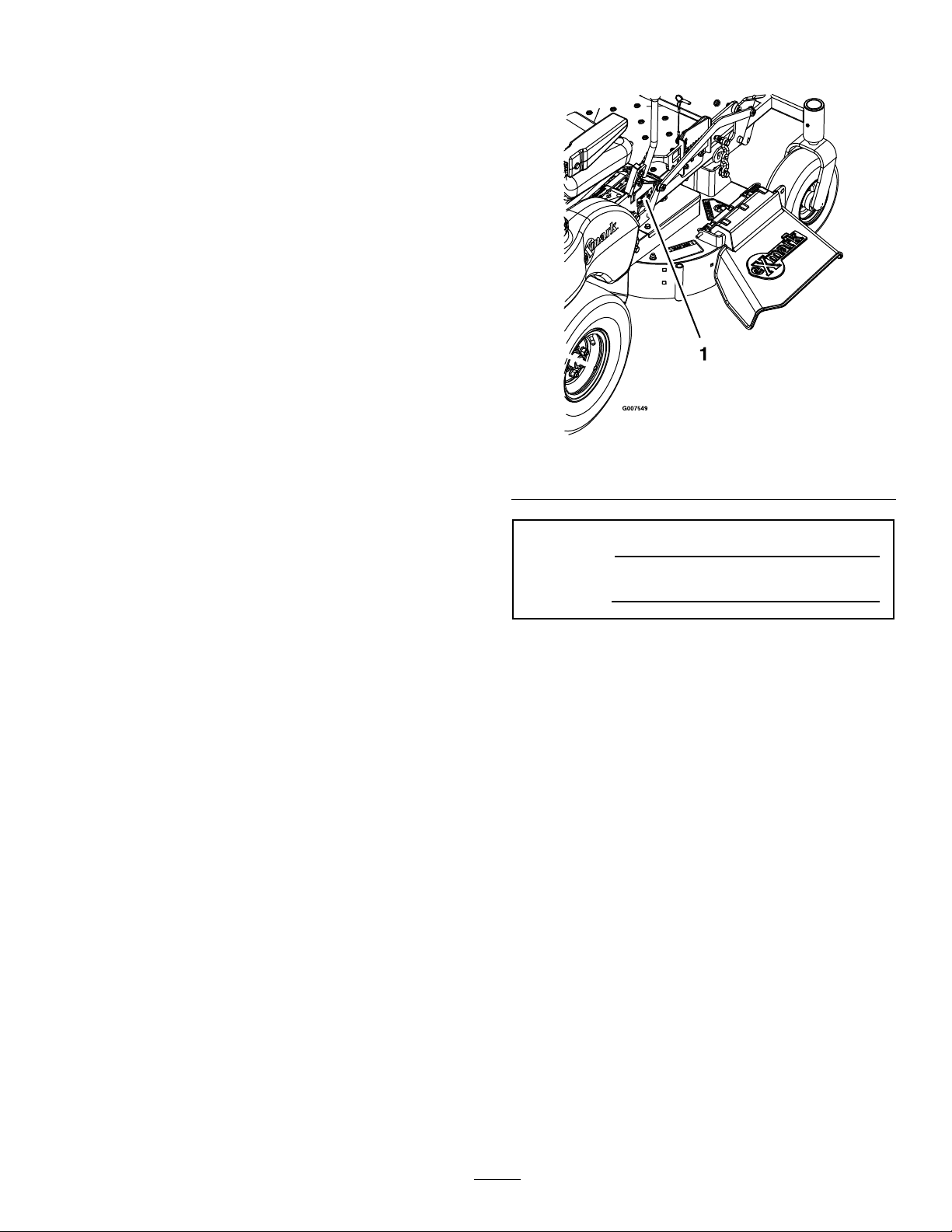
Figure1
1.Modelandserialnumberlocation
ModelNo.
SerialNo.
AllExmarkequipmentdealersanddistributorsare
keptinformedofthelatestmethodsofservicing
andareequippedtoprovidepromptandefcient
serviceintheeldorattheirservicestations.They
carryamplestockofservicepartsorcansecurethem
promptlyforyoufromthefactory.
AllExmarkpartsarethoroughlytestedandinspected
beforeleavingthefactory,however,attentionis
requiredonyourpartifyouaretoobtainthefullest
measureofsatisfactionandperformance.
Wheneveryouneedservice,genuineExmarkparts,
oradditionalinformation,contactanAuthorized
ServiceDealerorExmarkCustomerServiceandhave
themodelandserialnumbersofyourproductready .
Figure1identiesthelocationofthemodelandserial
numbersontheproduct.Writethenumbersinthe
spaceprovided.
3
Page 4

Contents
Introduction...........................................................3
Safety.....................................................................5
SafetyAlertSymbol.........................................5
SafeOperatingPractices..................................5
SafetyandInstructionalDecals.....................10
Specications.......................................................13
ModelNumbers............................................13
Systems.........................................................13
Dimensions...................................................14
TorqueRequirements....................................15
ProductOverview................................................15
Operation.............................................................16
Controls........................................................16
Pre-Start........................................................17
OperatingInstructions..................................18
Transporting.................................................20
Maintenance.........................................................22
RecommendedMaintenanceSchedule(s)...........22
PeriodicMaintenance.......................................23
CheckEngineOilLevel.................................23
CheckBatteryCharge....................................23
CheckMowerBlades.....................................24
CheckSafetyInterlockSystem.......................25
CheckforLooseHardware............................25
ServiceAirCleaner........................................26
ChangeEngineOil........................................26
CheckHydraulicOilLevel.............................26
CheckTirePressures.....................................26
CheckConditionOfBelts..............................26
LubricateGreaseFittings...............................27
LubricateCasterWheelHubs........................27
CheckSparkPlugs.........................................28
ChangeHydraulicSystemFilter.....................28
ThreadLockingAdhesives.............................29
MobilHTSGrease(OrFood-Grade
Anti-seize).................................................29
DielectricGrease...........................................29
Adjustments.....................................................30
DeckLeveling...............................................30
PumpDriveBeltTension...............................30
DeckDriveBeltTension................................30
ElectricClutchAdjustment............................30
MotionControlLinkageAdjustment.............30
AdjustThrottleLeverTension.......................31
Cleaning...........................................................31
CleanEngineAirCoolingSystem...................31
RemoveEngineShroudsandCleanCooling
Fins...........................................................31
CleanGrassBuild-UpUnderDeck................31
WasteDisposal..............................................32
Troubleshooting...................................................33
Schematics...........................................................35
4
Page 5

Safety
Safety
SafetyAlertSymbol
ThisSafetyAlertSymbol(Figure2)isusedbothin
thismanualandonthemachinetoidentifyimportant
safetymessageswhichmustbefollowedtoavoid
accidents
Thissymbolmeans:ATTENTION!BECOME
ALERT!YOURSAFETYISINVOLVED!
Figure2
1.Safetyalertsymbol
Thesafetyalertsymbolappearsaboveinformation
whichalertsyoutounsafeactionsorsituations
andwillbefollowedbythewordDANGER,
WARNING,orCAUTION.
DANGER:Whitelettering/Redbackground.
Indicatesanimminentlyhazardoussituationwhich,if
notavoided,Willresultindeathorseriousinjury.
WARNING:Blacklettering/Orangebackground.
Indicatesapotentiallyhazardoussituationwhich,if
notavoided,Couldresultindeathorseriousinjury.
CAUTION:Blacklettering/Yellowbackground.
Indicatesapotentiallyhazardoussituationwhich,if
notavoided,Mayresultinminorormoderateinjury.
•Neverletchildrenoruntrainedpeopleoperate
orservicetheequipment.Localregulationsmay
restricttheageoftheoperator.
•Onlyadultsandmatureteenagersshouldoperate
amower,andevenmatureteenagersshouldhave
adultsupervision.Besureateenager:
1.hasreadandunderstandstheOperator’s
Manualandrecognizestherisksinvolved;
2.issufcientlymaturetousecaution;and
3.isofsufcientsizeandweighttooperate
thecontrolscomfortablyandtomanagethe
mowerwithouttakingrisks.
•Theowner/usercanpreventandisresponsible
foraccidentsorinjuriesoccurringtohimselfor
herself,otherpeopleorproperty.
Preparation
•Evaluatetheterraintodeterminewhataccessories
andattachmentsareneededtoproperlyand
safelyperformthejob.Onlyuseaccessoriesand
attachmentsapprovedbyExmark.
•Wearappropriateclothingincludingsafetyglasses,
substantialfootwear,longtrousers,andhearing
protection.DoNotoperatewhenbarefootor
whenwearingopensandals.Longhair,loose
clothingorjewelrymaygettangledinmoving
parts.
CAUTION
Thismanualusestwootherwordstohighlight
information.Importantcallsattentiontospecial
mechanicalinformationandNoteemphasizes
generalinformationworthyofspecialattention.
SafeOperatingPractices
Training
•ReadtheOperator’sManualandothertraining
material.Iftheoperator(s)ormechanic(s)can
notreadEnglishitistheowner’sresponsibilityto
explainthismaterialtothem.
•Becomefamiliarwiththesafeoperationofthe
equipment,operatorcontrols,andsafetysigns.
•Alloperatorsandmechanicsshouldbetrained.
Theownerisresponsiblefortrainingtheusers.
Thismachineproducessoundlevelsinexcess
of85dBAattheoperator’searandcancause
hearinglossthroughextendedperiodsof
exposure.
Wearhearingprotectionwhenoperatingthis
machine.
•Inspecttheareawheretheequipmentistobe
usedandremoveallrocks,toys,sticks,wires,
bones,andotherforeignobjectswhichcanbe
thrownbythemachineandmaycausepersonal
injurytotheoperatororbystanders.
5
Page 6

Safety
DANGER
Incertainconditionsgasolineisextremely
ammableandvaporsareexplosive.
Areorexplosionfromgasolinecanburn
you,others,andcausepropertydamage.
•Fillthefueltankoutdoorsonlevelground,
inanopenarea,whentheengineiscold.
Wipeupanygasolinethatspills.
•Neverrellthefueltankordrainthe
machineindoorsorinsideanenclosed
trailer.
•DoNotllthefueltankcompletelyfull.
Fillthefueltanktothebottomoftheller
neck.Theemptyspaceinthetankallows
gasolinetoexpand.Overllingmayresult
infuelleakageordamagetotheengineor
emissionsystem(ifequipped).
•Neversmokewhenhandlinggasoline,and
stayawayfromanopenameorwhere
gasolinefumesmaybeignitedbyspark.
•Storegasolineinanapprovedcontainer
andkeepitoutofthereachofchildren.
•Addfuelbeforestartingtheengine.Never
removethecapofthefueltankoradd
fuelwhenengineisrunningorwhenthe
engineishot.
DANGER
Incertainconditionsduringfueling,static
electricitycanbereleasedcausingaspark
whichcanignitegasolinevapors.Areor
explosionfromgasolinecanburnyouand
othersandcausepropertydamage.
•Alwaysplacegasolinecontainersonthe
groundawayfromyourvehiclebefore
lling.
•DoNotllgasolinecontainersinsidea
vehicleoronatruckortrailerbedbecause
interiorcarpetsorplastictruckbedliners
mayinsulatethecontainerandslowthe
lossofanystaticcharge.
•Whenpractical,removegas-powered
equipmentfromthetruckortrailerand
refueltheequipmentwithitswheelson
theground.
•Ifthisisnotpossible,thenrefuelsuch
equipmentonatruckortrailerfroma
portablecontainer,ratherthanfroma
gasolinedispensernozzle.
•Ifagasolinedispensernozzlemustbe
used,keepthenozzleincontactwiththe
rimofthefueltankorcontaineropening
atalltimesuntilfuelingiscomplete.
•Iffuelisspilled,DoNotattempttostart
theengine.Moveawayfromtheareaof
thespillandavoidcreatinganysourceof
ignitionuntilfuelvaporshavedissipated.
•DoNotoperatewithoutentireexhaust
systeminplaceandinproperworking
condition.
WARNING
Gasolineisharmfulorfatalifswallowed.
Long-termexposuretovaporshascaused
cancerinlaboratoryanimals.Failuretouse
cautionmaycauseseriousinjuryorillness.
•Avoidprolongedbreathingofvapors.
•Keepfaceawayfromnozzleandgas
tank/containeropening.
•Keepawayfromeyesandskin.
•Neversiphonbymouth.
•Checkthattheoperator’spresencecontrols,
safetyswitches,andshieldsareattachedand
functioningproperly.DoNotoperateunlessthey
arefunctioningproperly.
6
Page 7

Safety
Operation
WARNING
Operatingengineparts,especiallythemufer,
becomeextremelyhot.Severeburnscanoccur
oncontactanddebris,suchasleaves,grass,
brush,etc.cancatchre.
•Allowengineparts,especiallythemufer,to
coolbeforetouching.
•Removeaccumulateddebrisfrommufer
andenginearea.
•Installandmaintaininworkingordera
sparkarresterbeforeusingequipment
onforest-covered,grass-covered,or
brush-coveredunimprovedland.
WARNING
Engineexhaustcontainscarbonmonoxide,
whichisanodorlessdeadlypoisonthatcankill
you.
DoNotrunengineindoorsorinasmallconned
areawheredangerouscarbonmonoxidefumes
cancollect.
•Operateonlyindaylightorgoodarticiallight,
keepingawayfromholesandhiddenhazards.
•Besurealldrivesareinneutralandparkingbrake
isengagedbeforestartingengine.
•Neveroperatethemowerwithdamagedguards,
shields,orcovers.Alwayshavesafetyshields,
guards,switchesandotherdevicesinplaceandin
properworkingcondition.
•Nevermowwiththedischargedeectorraised,
removedoralteredunlessthereisagrass
collectionsystemormulchkitinplaceand
workingproperly.
•DoNotchangetheenginegovernorsettingor
overspeedtheengine.
–Beforeclearingblockages.
–Wheneveryouleavethemower.
•Stopengine,waitforallmovingpartstostop,and
engageparkingbrake:
–Beforerefueling.
–Beforedumpingthegrasscatcher.
WARNING
Hands,feet,hair,clothing,oraccessoriescan
becomeentangledinrotatingparts.Contact
withtherotatingpartscancausetraumatic
amputationorseverelacerations.
•DoNotoperatethemachinewithout
guards,shields,andsafetydevicesin
placeandworkingproperly.
•Keephands,feet,hair,jewelry,orclothing
awayfromrotatingparts.
•NEVERcarrypassengers.DONOToperate
themowerwhenpeople,especiallychildren,or
petsareinthearea.
•Bealert,slowdownandusecautionwhenmaking
turns.Lookbehindandtothesidebefore
changingdirections.
•Stoptheblades,slowdown,andusecautionwhen
crossingsurfacesotherthangrassandwhen
transportingthemowertoandfromtheareato
bemowed.
•Beawareofthemowerdischargepathanddirect
dischargeawayfromothers.
•DoNotoperatethemowerundertheinuence
ofalcoholordrugs.
•Useextremecarewhenloadingorunloadingthe
machineintoatrailerortruck.
•Usecarewhenapproachingblindcorners,shrubs,
trees,orotherobjectsthatmayobscurevision.
•Stopengine,waitforallmovingpartstostop,
removekeyandengageparkingbrake:
–Beforechecking,cleaningorworkingonthe
mower.
–Afterstrikingaforeignobjectorabnormal
vibrationoccurs(inspectthemowerfor
damageandmakerepairsbeforerestarting
andoperatingthemower).
SlopeOperation
UseExtremecautionwhenmowingand/orturning
onslopesaslossoftractionand/ortip-overcould
occur.Theoperatorisresponsibleforsafeoperation
onslopes.
7
Page 8
Safety
DANGER
Operatingonwetgrassorsteepslopescancause
slidingandlossofcontrol.Wheelsdroppingover
edges,ditches,steepbanks,orwatercancause
rollovers,whichmayresultinseriousinjury,
deathordrowning.
•DoNotmowslopeswhengrassiswet.
•DoNotmowneardrop-offsornearwater.
•DoNotmowslopesgreaterthan15degrees.
•Reducespeedanduseextremecautionon
slopes.
•Avoidsuddenturnsorrapidspeedchanges.
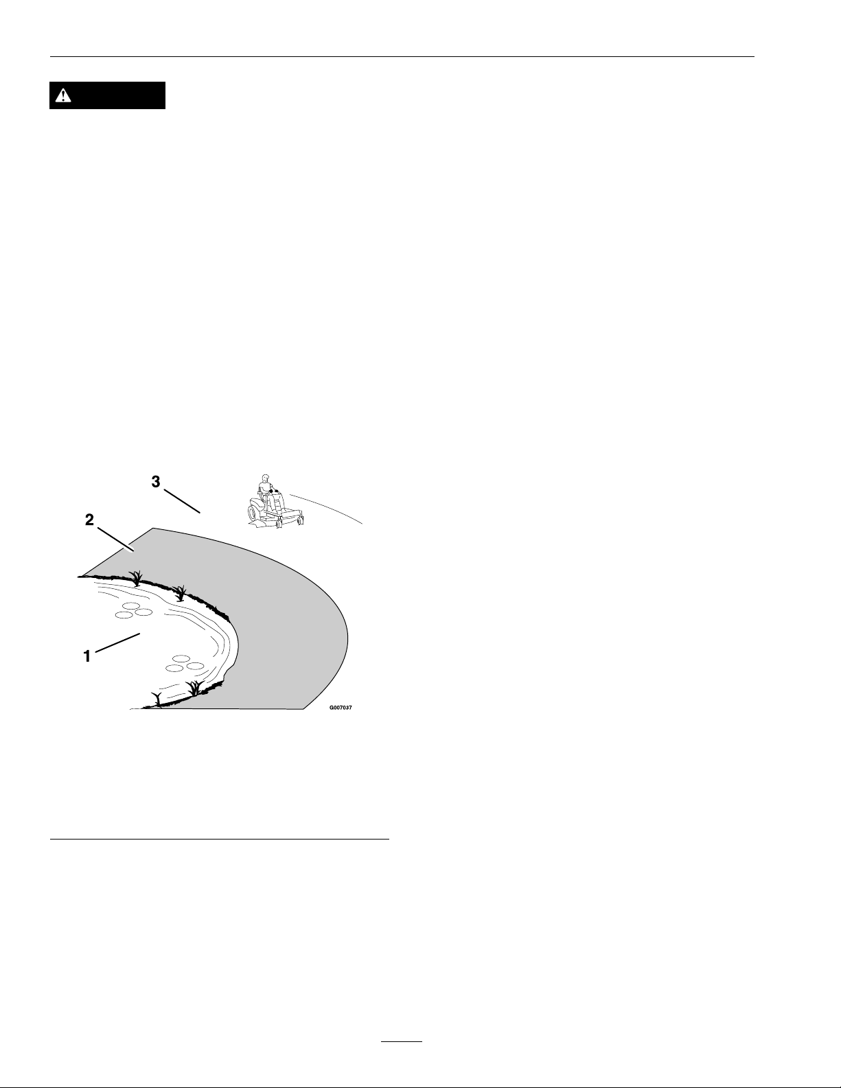
•Seeinsidethebackcovertodeterminethe
approximateslopeangleoftheareatobemowed.
•Useawalkbehindmowerand/orahandtrimmer
neardrop-offs,ditches,steepbanksorwater.
(Figure3).
•Beawarethatoperatingonwetgrass,acrosssteep
slopesordownhillmaycausethemowertolose
traction.Lossoftractiontothedrivewheelsmay
resultinslidingandalossofbrakingandsteering.
•Alwaysavoidsuddenstartingorstoppingona
slope.Iftireslosetraction,disengagetheblades
andproceedslowlyofftheslope.
•Followthemanufacturer’srecommendationsfor
wheelweightsorcounterweightstoimprove
stability.
•Useextremecarewithgrasscatchersor
attachments.Thesecanchangethestabilityofthe
machineandcauselossofcontrol.
MaintenanceandStorage
•Disengagedrives,lowerimplement,setparking
brake,stopengineandremovekeyordisconnect
sparkplugwire.Waitforallmovementtostop
beforeadjusting,cleaningorrepairing.
•Keepengine,enginearea,andpumpdrivebelt
compartmentfreefromaccumulationofgrass,
leaves,excessivegreaseoroil,andotherdebris
whichcanaccumulateintheseareas.These
materialscanbecomecombustibleandmayresult
inare.
Figure3
1.Water
2.DangerZone-Useawalkbehindmowerand/orhand
trimmeronslopesgreaterthan15degrees,near
drop-offs,andwater.
3.SafeZone-Usethemowerhereonslopeslessthan15
degrees
•Removeormarkobstaclessuchasrocks,tree
limbs,etc.fromthemowingarea.Tallgrasscan
hideobstacles.
•Watchforditches,holes,rocks,dipsandrisesthat
changetheoperatingangle,asroughterraincould
overturnthemachine.
•Avoidsuddenstartswhenmowinguphillbecause
themowermaytipbackwards.
•LetenginecoolbeforestoringandDoNotstore
nearameoranyenclosedareawhereopenpilot
lightsorheatappliancesarepresent.
•Shutofffuelwhilestoringortransporting.Do
Notstorefuelnearamesordrainindoors.
•Parkmachineonlevelground.Neverallow
untrainedpersonneltoservicemachine.
•Usejackstandstosupportcomponentswhen
required.
•Carefullyreleasepressurefromcomponentswith
storedenergy.
•Disconnectbatteryorremovesparkplugwire
beforemakinganyrepairs.Disconnectthe
negativeterminalrstandthepositivelast.
Reconnectpositiverstandnegativelast.
•Usecarewhencheckingblades.Wraptheblade(s)
orweargloves,andusecautionwhenservicing
them.Onlyreplacedamagedblades.Never
straightenorweldthem.
•Keephandsandfeetawayfrommovingparts.
Ifpossible,DoNotmakeadjustmentswiththe
enginerunning.
8
Page 9

Safety
•Chargebatteriesinanopenwellventilatedarea,
awayfromsparkandames.Unplugcharger
beforeconnectingordisconnectingfrombattery.
Wearprotectiveclothinganduseinsulatedtools.
DANGER
Chargingorjumpstartingthebatterymay
produceexplosivegases.Batterygasescan
explodecausingseriousinjury.
•Keepsparks,ames,orcigarettesaway
frombattery.
•Ventilatewhenchargingorusingbattery
inanenclosedspace.
•Makesureventingpathofbatteryis
alwaysopenoncebatteryislledwith
acid.
•Alwaysshieldeyesandfacefrombattery.
DANGER
Batteryelectrolytecontainssulfuricacid,
whichispoisonousandcancausesevere
burns.Swallowingelectrolytecanbefatalor
ifittouchesskincancausesevereburns.
•Wearsafetyglassestoshieldeyes,and
rubberglovestoprotectskinandclothing
whenhandlingelectrolyte.
•DoNotswallowelectrolyte.
•Intheeventofanaccident,ushwith
waterandcalladoctorimmediately.
CAUTION
WARNING
Removingstandardoriginalequipmentparts,
orusingnon-Exmarkreplacementpartsand
accessoriesmayalterthewarranty,traction,and
safetyofthemachine.Failuretouseoriginal
Exmarkpartscouldcauseseriousinjuryor
death.
Replaceallpartsincluding,butnotlimitedto
tires,belts,andbladeswithoriginalExmark
parts.
WARNING
Hydraulicuidescapingunderpressure
canpenetrateskinandcauseinjury.Fluid
accidentallyinjectedintotheskinmustbe
surgicallyremovedwithinafewhoursbyadoctor
familiarwiththisformofinjuryorgangrenemay
result.
•Ifequipped,makesureallhydraulicuid
hosesandlinesareingoodconditionandall
hydraulicconnectionsandttingsaretight
beforeapplyingpressuretohydraulicsystem.
•Keepbodyandhandsawayfrompinhole
leaksornozzlesthatejecthighpressure
hydraulicuid.
•Usecardboardorpaper,notyourhands,to
ndhydraulicleaks.
•Safelyrelieveallpressureinthehydraulic
systembyplacingthemotioncontrollevers
inneutralandshuttingofftheenginebefore
performinganyworkonthehydraulicsystem.
Iftheignitionisinthe“ON”positionthere
ispotentialforsparksandengagement
ofcomponents.Sparkscouldcausean
explosionormovingpartscouldaccidentally
engagecausingpersonalinjury
Besureignitionswitchisinthe“OFF”
positionbeforechargingthebattery.
•Keepallguards,shieldsandallsafetydevicesin
placeandinsafeworkingcondition.
•Checkallboltsfrequentlytomaintainproper
tightness.
•Frequentlycheckforwornordeteriorating
componentsthatcouldcreateahazard.
9
Page 10

Safety
SafetyandInstructionalDecals
•Keepallsafetysignslegible.Removeallgrease,
dirtanddebrisfromsafetysignsandinstructional
labels.
•Replaceallworn,damaged,ormissingsafety
signs.
•Whenreplacementcomponentsareinstalled,be
surethatcurrentsafetysignsareafxedtothe
replacedcomponents.
•Ifanattachmentoraccessoryhasbeeninstalled,
makesurecurrentsafetysignsarevisible.
•Newsafetysignsmaybeobtainedfrom
yourauthorizedExmarkequipmentdealeror
distributororfromExmarkMfg.Co.Inc.
•Safetysignsmaybeafxedbypeelingoffthe
backingtoexposetheadhesivesurface.Apply
onlytoaclean,drysurface.Smoothtoremove
anyairbubbles.
•Familiarizeyourselfwiththefollowingsafetysigns
andinstructionlabels.Theyarecriticaltothesafe
operationofyourExmarkcommercialmower.
93-8069
1-303508
1-403005
1-513747
1.Hotsurface/burnhazard—stayasafedistancefromthe
hotsurface.
98-5954
103-1077
1-513748
1.Fast3.Neutral
2.Slow
10
109-2356
4.Reverse
Page 11
Safety
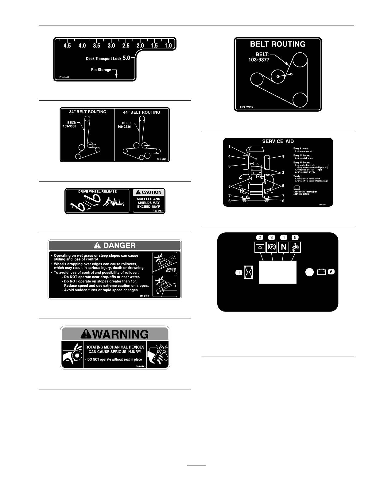
109-2463
109-2992
109-2465
116-0950
109-2467
109-2490
HourMessageDisplay
1.HourMeter4.Neutral
2.PTO5.Operator’spresence
3.ParkingBrake6.Battery
109-2862
switch
11
Page 12
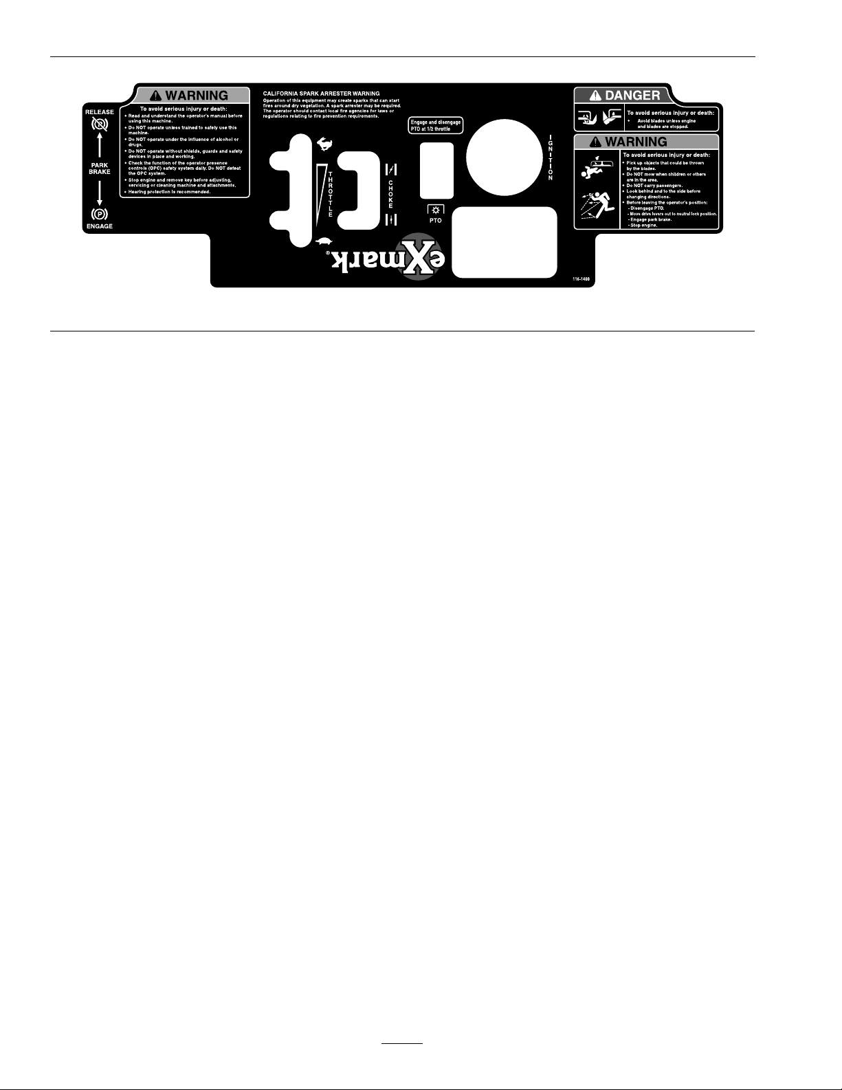
Safety
116-1400
12
Page 13

Specications
ModelNumbers
SerialNos:820,977andHigher
PHZ19KA343;PHZ19KA343CA
Specications
Systems
Engine
•EngineSpecications:SeeyourEngineOwner’s
Manual
•RPM:FullSpeed:3750±100RPM(NoLoad)
Idle:1400RPM
FuelSystem
•Capacity:7.7gal.(29.1L)
•TypeofFuel:Regularunleadedgasoline,87
octaneorhigher;containingnomorethan10%
methanolorethanol.
•FuelFilter:In-lineKawasakiP/N49019–7001
•FuelShut-OffValve:1/4turnincrements(“ON”,
“OFF”)
ElectricalSystem
•ChargingSystem:FlywheelAlternator
•ChargingCapacity:13amps
•BatteryType:BCIGroupU1
•BatteryVoltage:12Volt
•Polarity:NegativeGround
•Fuses:
–30ampmainfuse
–25ampchargingsystemfuse
–10ampclutchfuse
•OperatormustbeinseatwhenPTOisengaged,
brakeisdisengaged,ormotioncontrolleversare
movedinorenginewillstop.
•Enginewillstopifeithertheleft,theright,or
bothleversaremovedfromneutrallockposition
whilebrakeisengaged.
OperatorControls
•SteeringandMotionControl:
Note:Motioncontrolleversareadjustableto
twoheights.
–Separatelevers,oneachsideoftheconsole,
controlspeedanddirectionoftravelofthe
respectivedrivewheels.
–Steeringiscontrolledbyvaryingtheposition
oftheleversrelativetoeachother.
–Movingmotioncontrolleversoutward(in
slots)locksthedrivesysteminneutral.
•PTOEngagementSwitch:Engageselectricclutch
(todrivebelt)whichengagesmowerblades.
•ParkingBrakeLever:Engagesparkingbrake.
•DeckHeightAdjustmentLever:Setscutting
heighttodesiredposition.
•DeckLiftAssistLever:Footpedalthatassists
inraisingthedeck.
Seat
•Type:Standardseatwithhighback,foampadded,
(internalsuspension)andarmrests.
SafetyInterlockSystem
•LCDindicatorsappearforthePTO ,parkbrake,
drivelevers,andoperatorpresenceinthemessage
displayonthecenterconsole.
•PTOmustbedisengaged,brakeengaged,and
motioncontrolleversout(neutrallock)tostart
engine.(Itisnotnecessaryfortheoperatortobe
intheseattostarttheengine.)
•Mounting:Hingedtotiltupforaccesstobattery
andothercomponents.Heldintiltedposition
withlanyard.Adjustableforeandaftseattrack.
•Armrests:Standard–foampaddedip-up
armrests.
•SeatSafetySwitch:Incorporatedintothe
SafetyInterlockSystem.Timedelayseatswitch
eliminatesroughgroundcut-outs.
13
Page 14

Specications
HydrostaticGroundDriveSystem
•HydrostaticDrive:TwoHydroGearZT2800
Integrateddrivesystems.
•HydraulicOilType:UseExmarkPremiumHydro
Oil.
•Speeds:
–0-7.2mph(11.6km/hr)forward.
–0-4.0mph(6.4km/hr)reverse.
•Drivewheelreleasesallowmachinetobemoved
whenengineisnotrunningandbrakeisoff(left
andrightsidesofengine).
Tires&Wheels
DriveFrontCaster
Pneumatic
(Air-Filled)
Quantity
Tread
Size18x7.00-811x4.00-5
PlyRating
Pressure
22
TurfMateSmooth
4
13psi(90kPa)
Semi-Pneumatic
•DeckDepth:5.0inches(12.7cm)
•CuttingHeightAdjustment:
Footoperateddeckliftleverisusedtoadjustthe
cuttingheightfrom1inch(2.5cm)to5inches
(12.7cm)in1/4inch(6.4mm)increments.
Thecuttingheightadjustmenthandlehasa
transportpositionandalladjustmentscanbe
madewhiletheoperatorremainsseated.
•MulchingKit:Optional.
Dimensions
OverallWidth:
WithoutDeck34.5inches(87.6cm)
DeectorUp35.0inches(89.0cm)
DeectorDown44.0inches(111.8cm)
OverallLength:
70.0inches(177.8cm)
OverallHeight:
CuttingDeck
•CuttingWidth:34.5inches(87.6cm)
•Discharge:Side
•BladeSize:(2ea.)17.50inches(44.5cm)
•BladeSpindles:Solidsteelspindleswith1inch
(25.4mm)I.D.bearings.
•DeckDrive:
–Electricclutchmountedonverticalengine
shaft.
–Bladesaredrivenbyonebelt
(w/self-tensioningidler)directfrom
theengine.
•Deck:
Fulloatingdeckisattachedtoout-frontsupport
frame.
Twooptionalanti-scalprollers.
Deckdesignallowsforbagging,mulchingorside
discharge.
39.0inches(99.1cm)
TreadWidth:(CentertoCenterof
Tires,Widthwise)
DriveWheels26.5inches(67.3cm)
CasterWheels29.0inches(73.7cm)
WheelBase:(CenterofCasterTireto
CenterofDriveTire)
45.0inches(114.3cm)
CurbWeight:
570lb(258.5kg)
14
Page 15

ProductOverview
TorqueRequirements
BoltLocation
CutterHousingSpindle
Nut
BladeMountingBolt115-120ft-lb
Anti-ScalpRollerNyloc
Nut
EngineMountingBolts
WheelLugNuts
ClutchRetainingBolt
(securedwiththreadlocker)
Torque
140-145ft-lb
(190-197N-m)
(156-163N-m)
40-45ft-lb(54-61N-m)
25-30ft-lb(34-41N-m)
90-95ft-lb(122-129N-m)
55-60ft-lb(75-81N-m)
ProductOverview
Figure4
1.FuelCap
2.MotionControlLever5.Height-of-CutFootLever
3.Controls
4.ParkingBrakeLever
15
Page 16

Operation
Operation
Note:Determinetheleftandrightsidesofthe
machinefromthenormaloperatingposition.
Controls
MotionControlLevers
Themotioncontrolleverslocatedoneachsideofthe
consolecontroltheforwardandreversemotionof
themachine.Theleverscontroltheowofhydraulic
oilfromthehydrostaticpumptothedrivewheel
motorforeachside.
Movingtheleversforwardorbackwardturnsthe
wheelonthesamesideforwardorinreverse.Wheel
speedisproportionaltotheamounttheleveris
moved.
Movingtheleversoutwardfromthecenterposition
intotheT-slotlocksthemintheneutralposition
Figure7).
(
Whenthemotioncontrolleversareintheneutral
position,theLCDindicatorappearsinthemessage
displayonthecenterconsole(see
Figure6).
Thechokeisusedtoaidinstartingacoldengine.
Movingthechokeleverforwardwillputthechokein
the“ON”positionandmovingthechokeleverto
therearwillputthechokeinthe“OFF”position.
DoNotrunawarmenginewithchokeinthe“ON”
position.
ThrottleControl
Locatedonthecenteroftheconsole(totheleftside
ofthechoke).
Thethrottleisusedtocontrolenginespeed.Moving
thethrottleleverforwardwillincreaseenginespeed
andmovingthethrottlelevertotherearwilldecrease
enginespeed.
BrakeLever
Locatedonleftsideoftheconsole.
Thebrakeleverengagesaparkingbrakeonthedrive
wheels.
Note:TheLCDindicatorappearsinthemessage
displayontheRHconsolewhentheparkbrakeis
engaged(see
Pulltheleverupandrearwardtoengagethebrake.
Figure6).
Figure5
1.HandlesOut(Neutral
Lock)
2.HandlesIn(Neutral)
3.FrontofUnit
4.Forward
5.Neutral
6.Reverse
7.NeutralLock
ChokeControl
Locatedonthecenteroftheconsole.
Pushtheleverforwardanddowntodisengagethe
brake.
Theunitmustbetieddownandbrakeengagedwhen
transporting.
IgnitionSwitch
Locatedrightofcenterontheconsole.
Theignitionswitchisusedtostartandstopthe
engine.Theswitchhasthreepositions“OFF”,“ON”
and“START”.Insertkeyintoswitchandrotate
clockwisetothe“ON”position.Rotateclockwiseto
thenextpositiontoengagethestarter(keymustbe
heldagainstspringpressureinthisposition).
Note:Brakemustbeengaged,motioncontrollevers
out(neutrallockposition)andPTOswitch“OFF”to
startengine.(Itisnotnecessaryfortheoperatorto
beintheseattostarttheengine.)
HourMeter
Locatedrightofcenterontheconsole(belowignition
switch).
16
Page 17

Operation
Thehourmeterrecordsthenumberofhoursthat
theenginehasrun.
Figure6
1.LCDIndicators
2.Lowvoltageindicatorlight
3.Hour/Voltagedisplay
Thehourmeterisrecordingwhenthedecimalpoint
isashinginHour/Voltagedisplay.
Hoursaredisplayedwhenthekeyisofforwhenthe
machineisrunning.
Drivewheelreleaseleversareusedtoreleasethe
hydrostaticdrivesystemtoallowthemachinetobe
pushedwithouttheenginerunning.
Pulleachleverrearwardandoutwardtolock.Pull
eachleverinwardandpushforwardtoreset.DoNot
towmachine.
PTOEngagementSwitch
Locatedrightofcenterontheconsole(leftsideof
ignitionswitch).
Switchmustbepulledouttothe“ROTATE”
positiontoengagetheblades.Switchispushedinto
the“STOP”positiontostoptheblades.
TheLCDindicatorwillappearwhenthePTOswitch
isdisengaged(seeFigure6).
LowVoltageIndicator
Locatedonthecenterconsoleinthemessagedisplay
(seeFigure6).
Note:Iftheignitionkeyisturnedtothe“ON”
positionforafewsecondsbeforecrankingthe
engine,thebatteryvoltagewilldisplayinthearea
wherethehoursarenormallydisplayed.
Note:TheLCDindicatorsappearwheneach
controlmeetsthe“safetostart”mode(e.g.the
indicatorturnsonwhentheoperatorisintheseat.)
Note:Thisswitchisnotalowoilsensorandwillnot
alerttheoperatoriftheengineoilislow .
FuelShut-OffValve
Thevalveislocatedinthefuellinemidwaybetween
thefueltankandtheenginebehindtheseat.
Thefuelshut-offvalveisusedtoshutoffthefuel
whenthemachinewillnotbeusedforafewdays,
duringtransporttoandfromthejobsite,andwhen
parkedinsideabuilding.
Rotatethevalve1/4turnclockwisetoshutofffuel.
Rotatethevalve1/4turncounterclockwisetoturn
onfuel.
Alowvoltagecondition(lessthan12.3volts)exists
whenthelowvoltageindicatorlightappearsonthe
messagedisplaywhiletheengineisrunning.
Iftheignitionkeyisturnedtothe“ON”positionfor
afewsecondsbeforecrankingtheengine,thebattery
voltagewilldisplayintheareawherethehoursare
normallydisplayed.
Note:Theindicatornormallyappearswhenthe
engineisoffandthekeyswitchisturnedtothe
“ON”position.
Pre-Start
Fillfueltankonlevelground.Forbestresultsuse
onlyclean,freshregulargradeunleadedgasolinewith
anoctaneratingof87orhigher.
Important:Neverusemethanol,gasoline
containingmethanol,gasoholcontainingmore
than10%ethanol,premiumgasoline,orwhite
gasbecausethefuelsystemcouldbedamaged.
DoNotaddoiltogasoline.
DriveWheelReleaseLevers
Locatedattherearofthemainframe.
DoNotoverllfueltank.Fillthefueltanktothe
bottomofthellerneck.Theemptyspaceinthe
tankallowsgasolinetoexpand.Overllingmayresult
infuelleakageordamagetotheengineoremission
system(ifequipped).
17
Page 18

Operation
Makesureyouunderstandthecontrols,their
locations,theirfunctions,andtheirsafety
requirements.
RefertotheMaintenancesectionandperformallthe
necessaryinspectionandmaintenancesteps.
OperatingInstructions
OpentheFuelShut-OffValve
Rotatethevalve1/4turncounterclockwisetoturn
onfuel.
StartingtheEngine
1.Movethemotioncontrolleversouttotheneutral
lockposition.
2.Pullupandbackontheparkingbrakeleverto
engagetheparkingbrake.
3.PushinonthePTOswitchtothe“STOP”
position.
Note:Itisnotnecessaryfortheoperatortobe
intheseattostarttheengine.
EngagingthePTO
DANGER
Therotatingbladesunderthemowerdeckare
dangerous.Bladecontactcancauseserious
injuryorkillyou.
DoNotputhandsorfeetunderthemoweror
mowerdeckwhenthebladesareengaged.
DANGER
Anuncovereddischargeopeningwillallow
objectstobethrowninanoperator’sor
bystander’sdirection.Also,contactwiththe
bladecouldoccur.Thrownobjectsorblade
contactcancauseseriousinjuryordeath.
Neveroperatethemowerwiththedischarge
deectorraised,removed,oralteredunlessthere
isagrasscollectionsystemormulchkitinplace
andworkingproperly.
ThePTOpush-pullswitchengagesthecuttingblades.
Besurethatallpersonsareclearofthemowerdeck
anddischargeareabeforeengagingPTO.
4.Placethethrottlemidwaybetweenthe“SLOW”
and“FAST”positions.
5.Onacoldengine,pushthechokeleverforward
intothe“ON”position.
Onawarmengine,leavethechokeinthe“OFF”
position.
6.Turnignitionswitchtothe“START”position.
Releasetheswitchassoonastheenginestarts.
Important:DoNotcranktheengine
continuouslyformorethantensecondsata
time.Iftheenginedoesnotstart,allowa60
secondcool-downperiodbetweenstarting
attempts.Failuretofollowtheseguidelines
canburnoutthestartermotor.
7.Ifthechokeisinthe“ON”position,gradually
returnchoketothe“OFF”positionastheengine
warmsup.
Important:Operatormustbeinseatbeforethe
PTOcanbeengaged.
1.Setthethrottletothe“MIDWAY”position.
2.PullthePTOswitchoutwardtothe“ROTATE”
position.
3.Placethethrottleinthe“FAST”positiontobegin
mowing.
DisengagingthePTO
1.Setthethrottletothe“MIDWAY”position.
2.PushthePTOswitchintothe“STOP”position
todisengagetheblades.
StoppingtheEngine
1.Bringtheunittoafullstop.
2.DisengagethePTO.
3.Movethemotioncontrolleversouttotheneutral
lockposition.
4.Engagetheparkingbrake.
5.Placethethrottlemidwaybetweenthe“SLOW”
and“FAST”positions.
18
Page 19

6.Allowtheenginetorunforaminimumof15
seconds,thenturntheignitionswitchtothe
“OFF”positiontostoptheengine.
7.Removethekeytopreventchildrenorother
unauthorizedpersonsfromstartingengine.
8.Closethefuelshut-offvalvewhenthemachine
willnotbeinuseforafewdays,when
transporting,orwhentheunitisparkedinside
abuilding.
DrivingtheMachine
Operation
CAUTION
Machinecanspinveryrapidlybypositioningone
levertoomuchaheadoftheother.Operatormay
losecontrolofthemachine,whichmaycause
damagetothemachineorinjury.
•Usecautionwhenmakingturns.
•Slowthemachinedownbeforemakingsharp
turns.
Important:Tobeginmovement(forwardor
backward)theoperatormustbeintheseat,the
brakelevermustbedisengaged(pusheddown)
beforethemotioncontrolleverscanbemovedin
ortheenginewillstop.
WhenleversarecenteredintheT-slotthedrive
systemisintheneutralposition.Withleversmoved
outintheT-slotthedrivesystemisintheneutrallock
position(
Note:The“N”LCDindicatorappearswhenboth
leversareintheneutrallockposition.
Figure7).
Figure7
1.HandlesOut(Neutral
Lock)
2.HandlesIn(Neutral)
3.FrontofUnit
4.Forward
5.Neutral
6.Reverse
7.NeutralLock
DrivingForward
1.Releasetheparkingbrake.
2.Movethemotioncontrolleversinwardtothe
centertotheneutralunlockedposition.
3.Tomoveforwardinastraightlineapplyequal
forwardpressuretobothlevers.
Toturnleftorright,pullthemotioncontrollever
backtowardneutralinthedirectiondesired.
Themachinewillmovefasterthefartherthe
motioncontrolleversaremovedawayfrom
neutral.
4.Tostop,pullthemotioncontrolleversbackto
theneutralposition.
19
Page 20

Operation
Thedeckcanberaisedbypushingdownonthe
footoperateddeckliftassistleverlocatedatthe
frontrightcorneroftheoorpan.
Note:Whenchangingthecuttingheight
positions,alwayscometoacompletestop
anddisengagethePTO.
Figure9
1.Transportpositionand5inch(12.7cm)cuttingheight
position
Figure8
1.HandlesOut(Neutral
Lock)
2.HandlesIn(Neutral)
3.FrontofUnit
4.Forward
5.Reverse
DrivinginReverse
1.Movethemotioncontrolleversinwardtothe
centertotheneutralunlockedposition.
2.Tomoverearwardinastraightlineapplyingequal
pressurepullbothmotioncontrolleversrearward.
Toturnleftorright,releasepressureonthe
motioncontrollevertowardthedirectiondesired.
3.Tostop,pushthemotioncontrolleverstothe
neutralposition.
AdjustingtheCuttingHeight
Thecuttingheightofthemowerdeckisadjusted
from1inchto5inches(2.5cmto12.7cm)in1/4
inch(6.4mm)increments.
1.Stopthemachineandmovethemotioncontrol
leversoutwardtotheneutrallockedposition.
4.Inserttheheightadjustmentpinintothehole
correspondingtothedesiredcuttingheightand
installthehairpincotterpin.
Seethedecalonthesideofthedeckliftplatefor
cutheights.
5.Movethedeckheightleveroutofthetransport
position(or5inch(12.7cm)cuttingheight)and
downontotheheightadjustmentpintomowat
selectedheight.
6.Totransport,moveleverbackuptotransport(or
5inch(12.7cm)cuttingheight)position.
Transporting
TransportingaUnit
Useaheavy-dutytrailerortrucktotransportthe
machine.Lockbrakeandblockwheels.Securely
fastenthemachinetothetrailerortruckwithstraps,
chains,cable,orropes.Besurethatthetrailerortruck
hasallnecessarylightingandmarkingasrequiredby
law .Secureatrailerwithasafetychain.
2.DisengagethePTO.
3.Raisethedeckheightlevertothetransport
position(alsothe5inch(12.7cm)cuttingheight
position)(
Figure9).
20
Page 21

Operation
CAUTION
Thisunitdoesnothaveproperturnsignals,
lights,reectivemarkings,oraslowmoving
vehicleemblem.Drivingonastreetorroadway
withoutsuchequipmentisdangerousand
canleadtoaccidentscausingpersonalinjury.
Drivingonastreetorroadwaywithoutsuch
equipmentmayalsobeaviolationofStatelaws
andtheoperatormaybesubjecttotrafctickets
and/ornes.
DoNotdriveaunitonapublicstreetorroadway .
WARNING
Loadingaunitonatrailerortruckincreases
thepossibilityofbackwardtip-over.Backward
tip-overcouldcauseseriousinjuryordeath.
•Useextremecautionwhenoperatingaunit
onaramp.
•Useonlyasingle,fullwidthramp;DoNot
useindividualrampsforeachsideoftheunit.
anglemaycausemowerdeckcomponentstoget
caughtastheunitmovesfromramptotraileror
truck.Steeperanglesmayalsocausetheunittotip
backward.Ifloadingonornearaslope,position
thetrailerortrucksoitisonthedownsideofthe
slopeandtherampextendsuptheslope.Thiswill
minimizetherampangle.Thetrailerortruckshould
beaslevelaspossible.
Important:DoNotattempttoturntheunit
whileontheramp,youmaylosecontroland
driveofftheside.
Avoidsuddenaccelerationwhendrivinguparamp
andsuddendecelerationwhenbackingdownaramp.
Bothmaneuverscancausetheunittotipbackward.
•Ifindividualrampsmustbeused,useenough
rampstocreateanunbrokenrampsurface
widerthantheunit.
•DoNotexceeda15°anglebetweenrampand
groundorbetweenrampandtrailerortruck.
•Avoidsuddenaccelerationwhiledrivingunit
uparamptoavoidtippingbackward.
•Avoidsuddendecelerationwhilebackingunit
downaramptoavoidtippingbackward.
LoadingaUnit
Useextremecautionwhenloadingunitsontrailersor
trucks.Onefullwidthrampthatiswideenoughto
extendbeyondthereartiresisrecommendedinstead
ofindividualrampsforeachsideoftheunit.The
lowerrearsectionofthetractorframeextendsback
betweentherearwheelsandservesasastopfor
tippingbackward.Havingafullwidthrampprovides
asurfacefortheframememberstocontactifthe
unitstartstotipbackward.Ifitisnotpossibletouse
onefullwidthramp,useenoughindividualrampsto
simulateafullwidthcontinuousramp.
Rampshouldbelongenoughsothattheangles
betweentherampandthegroundandtherampand
thetrailerortruckDoNotexceed15°.Asteeper
21
Page 22

Maintenance
Maintenance
Note:Determinetheleftandrightsidesofthemachinefromthenormaloperatingposition.
WARNING
Whilemaintenanceoradjustmentsarebeing
made,someonecouldstarttheengine.
Accidentalstartingoftheenginecouldseriously
injureyouorotherbystanders.
Removethekeyfromtheignitionswitch,engage
parkingbrake,andpullthewire(s)offthespark
plug(s)beforeyoudoanymaintenance.Also
pushthewire(s)asidesoitdoesnotaccidentally
contactthesparkplug(s).
RecommendedMaintenanceSchedule(s)
MaintenanceService
Interval
Aftertherst5hours
Aftertherst250hours
Beforeeachuseordaily
MaintenanceProcedure
•Changetheengineoil.
•Changethehydrauliclter.
•Checktheengineoillevel.
•Checkthemowerblades.
•Checkthesafetyinterlocksystem.
•Checkforloosehardware.
•Cleantheengineaircoolingsystem.
•Cleanthegrassbuild-upfromunderthedeck.
WARNING
Theenginecanbecomeveryhot.T ouchingahot
enginecancausesevereburns.
Allowtheenginetocoolcompletelybefore
serviceormakingrepairsaroundtheenginearea.
Every25hours
Every40hours
Every50hours
Every80hours
Every100hours
Every160hours
Every500hours
•Greasethebeltidlers.
•Checkthehydraulicoillevel.
•Checkthetirepressures.
•Checktheconditionofthebelts.
•Greasethedeckpivots.
•Servicetheaircleaner.(Mayneedmoreoftenundersevereconditions.SeetheEngine
Owner’sManualforadditionalinformation.)
•Removeengineshroudsandcleancoolingns.
•Changetheengineoil.(Mayneedmoreoftenundersevereconditions.)
•Greasethebrakehandlepivot.
•Checkthesparkplugs.
•Changethehydrauliclter(Every250hours/yearlyifusingMobil115W50)
Monthly
Yearly
•Checkthebatterycharge.
•Greasethefrontcasterwheelbearings.
•Greasefrontcasterpivots.
•Lubricatethecasterwheelhubs.
22
Page 23

Maintenance
PeriodicMaintenance
CheckEngineOilLevel
ServiceInterval:Beforeeachuseordaily
1.Stopengineandwaitforallmovingpartstostop.
Makesureunitisonalevelsurface.
2.Checkwithenginecold.
3.Cleanareaarounddipstick.Removedipstickand
wipeoiloff.Reinsertthedipstick.Screwinto
place.Removethedipstickandreadtheoillevel.
4.Iftheoillevelislow ,wipeofftheareaaroundthe
oilllcap,removecapandlltothe“FULL”
markonthedipstick.Useoilasspeciedin
EngineOwner’sManual.DoNotoverll.
Important:DoNotoperatetheenginewiththe
oillevelbelowthe“LOW”(or“ADD”)markon
thedipstick,oroverthe“FULL”mark.
CheckBatteryCharge
Important:Makesurethenegativebatterycable
isdisconnectedandthebatterychargerusedfor
chargingthebatteryhasanoutputof16voltsand
7ampsorlesstoavoiddamagingthebattery(see
chartforrecommendedchargersettings).
Voltage
Reading
12.6or
greater
12.4–12.675–100%
12.2–12.450–75%
12.0–12.225–50%
11.7–12.00–25%
11.7orless
Percent
Charge
100%
0%
Maximum
Charger
Settings
16volts/7
amps
16volts/7
amps
16volts/7
amps
14.4volts/4
amps
14.4volts/4
amps
14.4volts/2
amps
Charging
Interval
No
Charging
Required
30Minutes
1Hour
2Hours
3Hours
6Hoursor
More
ServiceInterval:Monthly
WARNING
CALIFORNIA
Proposition65Warning
Batteryposts,terminals,andrelated
accessoriescontainleadandlead
compounds,chemicalsknowntotheStateof
Californiatocausecancerandreproductive
harm.Washhandsafterhandling.
Allowingbatteriestostandforanextendedperiodof
timewithoutrechargingthemwillresultinreduced
performanceandservicelife.T opreserveoptimum
batteryperformanceandlife,rechargebatteriesin
storagewhentheopencircuitvoltagedropsto12.4
volts.
Note:Topreventdamageduetofreezing,battery
shouldbefullychargedbeforeputtingawayfor
winterstorage.
Checkthevoltageofthebatterywithadigital
voltmeter.Locatethevoltagereadingofthebatteryin
thetableandchargethebatteryfortherecommended
timeintervaltobringthechargeuptoafullcharge
of12.6voltsorgreater.
RecommendedJump
StartingProcedure
ServiceInterval:Asrequired
1.Checktheweakbatteryforterminalcorrosion
(white,green,orblue“snow”),itmustbecleaned
offpriortojumpstarting.Cleanandtighten
connectionsasnecessary.
CAUTION
Corrosionorlooseconnectionscancause
unwantedelectricalvoltagespikesatanytime
duringthejumpstartingprocedure.
DoNotattempttojumpstartwithlooseor
corrodedbatteryterminalsordamagetothe
enginemayoccur.
DANGER
Jumpstartingaweakbatterythatiscracked,
frozen,haslowelectrolytelevel,oran
open/shortedbatterycell,cancausean
explosionresultinginseriouspersonalinjury.
DoNotjumpstartaweakbatteryifthese
conditionsexist.
23
Page 24

Maintenance
2.Makesuretheboosterisagoodandfullycharged
leadacidbatteryat12.6voltsorgreater.Use
properlysizedjumpercables(4to6AWG)with
shortlengthstoreducevoltagedropbetween
systems.Makesurethecablesarecolorcodedor
labeledforthecorrectpolarity.
CAUTION
Connectingthejumpercablesincorrectly
(wrongpolarity)canimmediatelydamagethe
electricalsystem.
Becertainofbatteryterminalpolarityand
jumpercablepolaritywhenhookingup
batteries.
Note:Thefollowinginstructionsareadapted
fromtheSAEJ1494Rev .Dec.2001–Battery
BoosterCables–SurfaceVehicleRecommended
Practice(SAE–SocietyofAutomotive
Engineers).
Figure10
1.Positive(+)cableondischargedbattery
2.Positive(+)cableonboosterbattery
3.Negative(–)cableontheboosterbattery
4.Negative(–)cableontheengineblock
5.Boosterbattery
6.Dischargedbattery
7.Engineblock
4.Connecttheotherendofthepositivecabletothe
positiveterminaloftheboosterbattery.
WARNING
Batteriescontainacidandproduceexplosive
gases.
•Shieldtheeyesandfacefromthebatteries
atalltimes.
•DoNotleanoverthebatteries.
Note:Besuretheventcapsaretightandlevel.
Placeadampcloth,ifavailable,overanyvent
capsonbothbatteries.Besurethevehiclesdo
nottouchandthatbothelectricalsystemsare
offandatthesameratedsystemvoltage.These
instructionsarefornegativegroundsystemsonly.
3.Connectthepositive(+)cabletothepositive(+)
terminalofthedischargedbatterythatiswiredto
thestarterorsolenoidasshownin
Figure10.
5.Connecttheblacknegative(–)cabletotheother
terminal(negative)oftheboosterbattery.
6.MAKETHEFINALCONNECTIONON
THEENGINEBLOCKOFTHESTALLED
VEHICLE(NOTTOTHENEGATIVEPOST)
AWAYFROMTHEBATTERY .STANDBACK.
7.Startthevehicleandremovethecablesinthe
reverseorderofconnection(theengineblock
(black)connectionisthersttodisconnect).
CheckMowerBlades
ServiceInterval:Beforeeachuseordaily
Important:Mowerbladesaresharp.Wrapthe
bladeorweargloves,anduseextracautionwhen
servicingthem.
1.Stopengine,waitforallmovingpartstostop,and
removekey.Engageparkingbrake.
2.Liftdeckandsecureinraisedpositionasstatedin
theCleanGrassBuild-UpUnderDecksection.
3.Inspectbladesandsharpenorreplaceasrequired.
4.Installbladeboltandspringdiscwasher.Besure
thespringdiscwasherconeisinstalledtowards
thebolthead.Placeablockofwoodbetween
frontorrearbafesandthebladethentorque
thebladeboltsto115–120ft-lb(156–163N-m)
(Figure11).
24
Page 25

Figure11
1.DoNotusewrenchhereforbladeinstallation.Maintain
140–145ft-lb(190–197N-m)
2.Use1inchwrenchheretoholdspindleforblade
replacement.
3.Conetowardsbolthead
4.Torqueto1 15–120ft-lb(156–163N-m)
Maintenance
leversintheneutrallockposition-startermust
notcrank.
Trytostartwithoperatorinseat,parkingbrake
engaged,PTOengagedandmotioncontrol
leversintheneutrallockposition-startermust
notcrank.
Trytostartwithoperatorinseat,parking
brakeengaged,PTOdisengaged,andtheleft
motioncontrolleverin,startermustnotcrank,
repeatagainwiththerightleverin,thenwith
bothleversin-startermustnotcrank.
2.Checkthekillcircuits.Runengineatone-third
throttle,disengageparkingbrakeandraiseoff
ofseat(butdonotgetoffofmachine)engine
mustinitiateshutdownafterapproximately1/2
secondhaselapsed(seathastimedelaykillswitch
topreventcut-outsonroughterrain).
Runengineatone-thirdthrottle,engagePTO
andraiseoffofseat(butdonotgetoffof
machine)enginemustinitiateshutdownafter
1/2secondhaselapsed.
WARNING
Incorrectinstallationofthebladeor
componentsusedtoretainthebladecan
bedangerous.Failuretousealloriginal
componentsandassembledasshowncould
allowabladeorbladecomponenttobe
thrownoutfromunderthedeckresultingin
seriouspersonalinjuryordeath.
AlwaysinstalltheoriginalExmarkblades,
springdiscwashers,andbladeboltsas
shown.
CheckSafetyInterlock
System
ServiceInterval:Beforeeachuseordaily
Note:Topreventenginecut-outsonroughterrain
theseatkillswitchhasa1/2seconddelay.
1.Checkstartingcircuit.Startershouldcrankwith,
parkingbrakeengaged,PTOdisengagedand
motioncontrolleversmovedoutintheneutral
lockposition.Theoperatordoesnotneedtobe
intheseattostarttheengine.
Trytostartwithoperatorinseat,parkingbrake
disengaged,PTOdisengagedandmotioncontrol
Runengineatone-thirdthrottle,withbrake
disengaged,moveleversinandraiseoffseat(but
donotgetoffofmachine)enginemustinitiate
shutdownafter1/2secondhaselapsed.
Again,runengineatone-thirdthrottle,brake
engaged,andmoveleftmotioncontrolleverin
-enginemustinitiateshutdown.
Repeatagainmovingtherightleverin,then
movingbothleversin-enginemustinitiate
shutdownwhetheroperatorisonseatornot.
Note:Ifmachinedoesnotpassanyofthesetests,
DoNotoperate.ContactyourauthorizedEXMARK
SERVICEDEALER.
Important:Itisessentialthatoperatorsafety
mechanismsbeconnectedandinproper
operatingconditionpriortouseformowing .
CheckforLooseHardware
ServiceInterval:Beforeeachuseordaily
1.Stopengine,waitforallmovingpartstostop,and
removekey.Engageparkingbrake.
2.Visuallyinspectmachineforanyloosehardware
oranyotherpossibleproblem.Tightenhardware
orcorrecttheproblembeforeoperating.
25
Page 26

Maintenance
ServiceAirCleaner
ServiceInterval:Every50hours—Service
theaircleaner.(May
needmoreoftenunder
severeconditions.See
theEngineOwner’s
Manualforadditional
information.)
1.Stopengine,waitforallmovingpartstostop,and
removekey.Engageparkingbrake.
2.SeeEngineOwner’sManualforcleaning
instructions.
ChangeEngineOil
ServiceInterval:Aftertherst5hours
Every100hours/Yearly
(whichevercomesrst)
(Mayneedmoreoften
undersevereconditions.)
1.Stopengine,waitforallmovingpartstostop,and
removekey.Engageparkingbrake.
2.Drainoilwhileengineiswarmfromoperation.
3.Theoildrainislocatedonrighthandsideof
engine.Placepanundermachinetocatchoil.Fit
hoseinliteraturepackoveroildrainvalve.Rotate
valve1/4turncounterclockwiseandgentlypull
outwardtoopenvalve.Allowoiltodrain,then
closevalvebypushinginwardandrotating1/4
turnclockwise.Removeandretainthehosefor
futureuse.
4.Replacetheoilltereveryotheroilchange.Clean
aroundoillterandunscrewltertoremove.
Beforereinstallingnewlter,applyathincoating
ofoilonthesurfaceoftherubberseal.Turn
lterclockwiseuntilrubbersealcontactsthelter
adapterthentightenlteranadditional1/2to
3/4turn.
1.Stopengineandwaitforallmovingpartstostop.
Engageparkingbrake.Allowenginetocool.
2.Cleanareaaroundhydraulicexpansionreservoir.
OillevelshouldbeattheFULLCOLDlineon
expansionreservoir.Ifnot,addoil.Useonly
ExmarkPremiumHydrooil.Replacehydraulic
reservoircapandtightenuntilsnug.DoNot
overtighten.DoNotoverll.
CheckTirePressures
ServiceInterval:Every40hours
1.Stopengine,waitforallmovingpartstostop,and
removekey.Engageparkingbrake.
2.Checktirepressureindrivetires.
3.Inatedrivetiresto13psi(90kPa).
4.Semi-pneumaticcastertiresdonotneedtobe
inated.
Note:DoNotaddanytypeoftirelinerorfoam
llmaterialtothetires.Excessiveloadscreatedby
foamlledtiresmaycausefailurestothehydrodrive
system,frame,andothercomponents.Foamlling
tireswillvoidthewarranty.
CheckConditionOfBelts
ServiceInterval:Every40hours
1.Stopengine,waitforallmovingpartstostop,and
removekey.Engageparkingbrake.
2.Checkunderenginedecktocheckpumpdrive
belt.
3.Removeleftandrightbeltshieldsondeckandlift
upoorpantoinspectdeckdrivebelt.
4.Forbeltadjustment,seethePumpDriveBelt
andDeckBeltTensionAdjustmentsections.
5.Cleanaroundoilllcapandremovecap.Fillto
speciedcapacityandreplacecap.
6.Useoilrecommendedinengineowner’smanual.
DoNotoverll.Starttheengineandcheckfor
leaks.Stopengineandrecheckoillevel.
CheckHydraulicOilLevel
ServiceInterval:Every40hours
26
Page 27

Maintenance
LubricateGreaseFittings
Note:Seechartforserviceintervals.
1.Stopengine,waitforallmovingpartstostop,and
removekey.Engageparkingbrake.
2.Lubricatettingswithonetotwopumpsof
NGLIgrade#2multi-purposegungrease.
Refertothefollowingchartforttinglocations
andlubricationschedule.
LubricationChart
Fitting
Locations
1.Belt
Idlers
2.Deck
Pivots
3.Front
Caster
Wheel
Bearings
4.Front
Caster
Pivots
5.Brake
Handle
Pivot
*Seestep3forspeciallubricationinstructionson
thefrontcasterpivotsandtheLubricateCaster
WheelHubssectionforspeciallubrication
instructionsonthefrontcasterswheelhubs.
Initial
Pumps
12
1
*0
*0
11
Numberof
Places
440Hours
2
2
Service
Interval
25Hours
*Yearly
*Yearly
160Hours
pumpwithgreaseuntilitoozesoutaroundtop
bearing.Removegreasezerkandthreadplugback
in.Placecapbackon.
LubricateCasterWheelHubs
ServiceInterval:Yearly
1.Stopengine,waitforallmovingpartstostop,and
removekey.Engageparkingbrake.
Figure12
1.Sealguard2.Spacernutwithwrench
ats
2.Removecasterwheelfromcasterforks.
3.Removesealguardsfromthewheelhub.
4.Removeoneofthespacernutsfromtheaxle
assemblyinthecasterwheel.Notethatthread
lockingadhesivehasbeenappliedtolockthe
spacernutstotheaxle.Removetheaxle(with
theotherspacernutstillassembledtoit)from
thewheelassembly.
3.Lubricatefrontcasterpivotsonceayear.Remove
hexplugandcap.Threadgreasezerkinholeand
5.Pryoutseals,andinspectbearingsforwearor
damageandreplaceifnecessary.
6.PackthebearingswithaNGLIgrade#1
multi-purposegrease.
7.Insertonebearing,onenewsealintothewheel.
Note:Seals(ExmarkP/N103-0063)mustbe
replaced.
8.Iftheaxleassemblyhashadbothspacernuts
removed(orbrokenloose),applyathreadlocking
adhesivetoonespacernutandthreadontothe
axlewiththewrenchatsfacingoutward.Do
Notthreadspacernutallofthewayontotheend
oftheaxle.Leaveapproximately1/8inch(3mm)
fromtheoutersurfaceofthespacernuttothe
endoftheaxleinsidethenut.
27
Page 28

Maintenance
9.Inserttheassemblednutandaxleintothewheel
onthesideofthewheelwiththenewsealand
bearing.
10.Withtheopenendofthewheelfacingup,ll
theareainsidethewheelaroundtheaxlefullof
NGLIgrade#1multi-purposegrease.
11.Insertthesecondbearingandnewsealintothe
wheel.
12.Applyathreadlockingadhesivetothe2ndspacer
nutandthreadontotheaxlewiththewrenchats
facingoutward.
13.Torquethenutto75-80in-lb(8-9N-m),loosen,
thenre-torqueto20-25in-lb(2-3N-m).Make
sureaxledoesnotextendbeyondeithernut.
14.Reinstallthesealguardsoverthewheelhuband
insertwheelintocasterfork.Reinstallcasterbolt
andtightennutfully.
Important:Topreventsealandbearingdamage,
checkthebearingadjustmentoften.Spinthe
castertire.Thetireshouldnotspinfreely
(morethan1or2revolutions)orhaveanyside
play.Ifthewheelspinsfreely,adjusttorqueon
spacernutuntilthereisaslightamountofdrag.
Reapplythreadlockingadhesive.
ChangeHydraulicSystem
Filter
ServiceInterval:Aftertherst250hours
Every500hours/Yearly
(whichevercomes
rst)thereafter
(Every250hours/Yearlyif
usingMobil115W50)
1.Stopengine,waitforallmovingpartstostop,and
removekey.Engageparkingbrake.
2.Locatethetwoltersunderthetransmissions.
Removelterguards.
3.Carefullycleanareaaroundlters.Itisimportant
thatnodirtorcontaminationenterhydraulic
system.
4.Unscrewlterstoremoveandallowoiltodrain
fromdrivesystem.
Important:Beforereinstallingnewlter,
applyathincoatofExmarkPremiumHydro
oilonthesurfaceoftherubberseal.
Turntheltersclockwiseuntilrubberseal
contactsthelteradapterthentightenthelter
anadditional1/2to3/4turn.
CheckSparkPlugs
ServiceInterval:Every160hours
Removesparkplugs,checkconditionandresetgaps,
orreplacewithnewplugs.SeeEngineOwner’ s
Manual.
ChangeFuelFilter
ServiceInterval:Asrequired
Afuellterisinstalledbetweenthefueltanksandthe
engine.Replacewhennecessary.
ReplacementFilters
Kawasaki
KawasakiP/N
49019–7001
5.Removetheventplugoneachtransmissionand
llthroughexpansionreservoir,whenoilcomes
outofventreinstallplug.Torqueplugsto180
in-lbs(20N-m).
Figure13
LeftSideShown
1.Leftreartire
2.Oillter
3.Ventplug
28
Page 29

Maintenance
6.AddoiluntilitreachestheFULLCOLDlineon
theexpansionreservoir.
ExmarkPremiumHydroOilisrecommended.
Refertothechartforanacceptablealternative:
HydroOil
ExmarkPremiumHydro
Oil(Preferred)
Mobil115W50
7.Raisetherearofmachineupandsupportwith
jackstands(orequivalentsupport)justhigh
enoughtoallowdrivewheelstoturnfreely .
ChangeInterval
500Hours
250Hours
CAUTION
Raisingthemowerforserviceormaintenance
relyingsolelyonmechanicalorhydraulic
jackscouldbedangerous.Themechanicalor
hydraulicjacksmaynotbeenoughsupport
ormaymalfunctionallowingtheunittofall,
whichcouldcauseinjury.
DoNotrelysolelyonmechanicalorhydraulic
jacksforsupport.Useadequatejackstands
orequivalentsupport.
FuelTank—Mounting
HardwareSpecications
ServiceInterval:Asrequired
Wheninstallingthenutsonthefueltankstuds,fully
tightenthenylocnutandbackoff1/2turn.This
allowsfornormalfueltankexpansionandcontraction
withchangesintemperatureandfuellevels.
ThreadLockingAdhesives
Threadlockingadhesivessuchas“Loctite242”
or“Fel-Pro,Pro-LockNutType”areusedonthe
followingfasteners:
•Clutchretainingboltintheendofengine
crankshaft.
•Casterwheelspacernuts.
•Cutterhousingspindlenut.
Adhesivessuchas“LoctiteRC/609orRC/680”or
“Fel-ProPro-LockRetainingIorRetainingII”are
usedonthefollowing:
Fueltankstuds,wherestudsareinsertedintotank.
8.Startengineandmovethrottlecontrolaheadto
1/2throttleposition.Disengageparkingbrake.
A.Withthebypassvalveopenandtheengine
running,slowlymovethedirectionalcontrol
inbothforwardandreverse(5or6times).
B.Withthebypassvalveclosedandtheengine
running,slowlymovethedirectionalcontrol
inbothforwardandreversedirections(5to6
times).
C.ItmaybenecessarytorepeatstepsAand
Buntilalltheairiscompletelypurgedfrom
thesystem.Whenthetransaxleoperatesat
normalnoiselevelsandmovessmoothly
forwardandreverseatnormalspeeds,then
thetransaxleisconsideredpurged.
Note:DoNotchangehydraulicsystemoil(except
forwhatcanbedrainedwhenchanginglter),unless
itisfelttheoilhasbeencontaminatedorbeen
extremelyhot.
Changingoilunnecessarilycoulddamagehydraulic
systembyintroducingcontaminatesintothesystem.
MobilHTSGrease(Or
Food-GradeAnti-seize)
MobilHTSgrease(orfood-gradeanti-seize)isused
inthefollowinglocations:
•Betweenthecutterhousingspindleandbearings.
•Betweenthecutterhousingspindleandsheave.
•Undertopcutterhousingbearingguard.
DielectricGrease
Dielectricgreaseisusedonallbladetypeelectrical
connectionstopreventcorrosionandlossofcontact.
29
Page 30

Maintenance
Adjustments
Note:DisengagePTO,shutoffengine,waitfor
allmovingpartstostop,engageparkingbrake,and
removekeybeforeservicing,cleaning,ormakingany
adjustmentstotheunit.
DeckLeveling
1.Positionmoweronaatsurface.
2.Stopengine,waitforallmovingpartstostop,and
removekey.Engageparkingbrake.
3.Checktirepressureindrivetires.Properination
pressurefortiresis13psi(90kPa).Adjustif
necessary.Semi-pneumaticcastertiresDoNot
needtobeinated.
4.Setanti-scalprollerstotopholes(ifinstalled)or
removethemcompletelyforthisadjustment.
5.Lowerthedecktothe11/2inch(3.8cm)height
position.Placetwo11/8inch(2.9cm)thick
blocksundertherearedgeofthecuttingdeck
skirt;oneoneachsideofthecuttingdeck.
6.Placea1inch(2.5cm)blockunderthecenter
frontedge,butnotundertheanti-scalproller
brackets.
7.Loosenthefourbottomchainboltsinslotsuntil
thedeckissupportedbytheblocks.Takethe
slackoutofthechainsandretightenthehardware.
8.Recheckthatblockstjustsnuglyunderthe
deckskirtandthatthetensiononallthechains
isapproximatelyequal.Makesureallchain
attachmentboltsaretight.
9.Repositionanti-scalprollers(ifinstalled)and
tightensecurely.
Note:Whenaboveadjustmentshavebeenmade,
thefrontofthedeckwillbeslightlylowerthanthe
rearofthedeck.
PumpDriveBeltTension
Self-tensioning-Noadjustmentnecessary.
MotionControlLinkage
Adjustment
Note:Therearetwoleverheightoptionsavailable.
Placetheleversinthetoptwoholestoincrease
heightofthelevers,orinthebottomtwoholesto
decreasetheheightofthelevers.
1.Aligntheleversfront/rearposition.Withthe
leversintheneutralposition,loosenthehardware
andadjusttheleversslidingand/ortiltingthe
lever(s)forwardorbackwarduntilproperly
alignedandtightenhardware(
Figure14
1.Motioncontrollevers
2.Springdiscwasher
2.Iftheendsofthelevershitagainsteachother,
whileinthedriveposition(leversrotatedinas
faraspossible),makeadjustmentsbymovingthe
leversoutwardstotheneutrallockpositionand
carefullybendingthemoutward.Movethemback
tothedrivepositionandcheckforclearance.
Repeatifnecessary.
3.Ifthemachineturnsrightorleftwhenhandlesare
pushedforwardtogether,adjustthestoponthe
sideoppositethedirectionofturn(see
Movethestopbackuntiltheunitdrivesstraight.
Readjusthandlesifnecessary.
Figure14).
3.3/8-16x1inchscrew
Figure15).
DeckDriveBeltTension
Self-tensioning–Noadjustmentnecessary.
ElectricClutchAdjustment
Noadjustmentnecessary.
30
Page 31

1.Adjuststop
Figure15
Maintenance
Cleaning
CleanEngineAirCooling
System
ServiceInterval:Beforeeachuseordaily
(Mayberequiredmore
oftenindryordirty
conditions.)
CAUTION
Excessivedebriscancausetheengineand
hydraulicsystemtooverheatwhichcancreate
arehazard.
Cleanalldebrisfromaroundtheengineand
hydraulicpumpsdaily.
AdjustThrottleLever
Tension
1.Stopengine,waitforallmovingpartstostop,and
removekey.Engageparkingbrake.
2.Tensioninthrottlelevercanbeadjustedby
adjustingthetightnessoftheleverpivotbolt,
whichislocatedundertheconsole(Figure16).
Figure16
1.Hexbolt5.Lever
2.Springdiscwashers
3.Tabwasher7.Hexlocknut
4.Frictionwasher
6.Bracket
1.Stopengine,waitforallmovingpartstostop,and
removekey.Engageparkingbrake.
2.Cleanalldebrisfromrotatingengineairintake
screenandfromaroundengineshrouding.
RemoveEngineShroudsand
CleanCoolingFins
ServiceInterval:Every80hours
1.Stopengine,waitforallmovingpartstostop,and
removekey.Engageparkingbrake.
2.Removecoolingshroudsfromengineandclean
coolingns.Alsocleandust,dirtandoilfrom
externalsurfacesofengine,whichcancause
impropercooling.
3.Makesurecoolingshroudsareproperly
reinstalled.Operatingtheenginewithout
coolingshroudswillcauseenginedamagedueto
overheating.
CleanGrassBuild-UpUnder
Deck
ServiceInterval:Beforeeachuseordaily
1.Stopengine,waitforallmovingpartstostop,and
removekey.Engageparkingbrake.
31
Page 32

Maintenance
2.Raisedecktothetransport(maximumcutting
height)position.Liftthefrontofunitandsupport
unitusingjackstandsorequivalentsupport.
3.Cleanoutanygrassbuild-upfromundersideof
deckandindischargechute.
WasteDisposal
MotorOilDisposal
Engineoilandhydraulicoilarebothpollutantsto
theenvironment.Disposeofusedoilatacertied
recyclingcenteroraccordingtoyourstateandlocal
regulations.
BatteryDisposal
DANGER
Batteryelectrolytecontainssulfuricacid,which
ispoisonousandcancausesevereburns.
Swallowingelectrolytecanbefatalorifittouches
skincancausesevereburns.
•Wearsafetyglassestoshieldeyes,andrubber
glovestoprotectskinandclothingwhen
handlingelectrolyte.
•DoNotswallowelectrolyte.
•Intheeventofanaccident,ushwithwater
andcalladoctorimmediately.
Federallawstatesthatbatteriesshouldnotbeplaced
inthegarbage.Managementanddisposalpractices
mustbewithinrelevantfederal,state,orlocallaws.
Ifabatteryisbeingreplacedoriftheunitcontaining
thebatteryisnolongeroperatingandisbeing
scrapped,takethebatterytoalocalcertiedrecycling
center.Ifnolocalrecyclingisavailablereturnthe
batterytoanycertiedbatteryreseller.
32
Page 33

Troubleshooting
Troubleshooting
Important:Itisessentialthatalloperatorsafetymechanismsbeconnectedandinproperoperating
conditionpriortomoweruse.
Whenaproblemoccurs,donotoverlookthesimplecauses.Forexample:startingproblemscouldbecaused
byanemptyfueltank.
Thefollowingtablelistssomeofthecommoncausesoftrouble.Donotattempttoserviceorreplacemajor
itemsoranyitemsthatcallforspecialtimingofadjustmentsprocedures(suchasvalves,governor,etc.).Have
thisworkdonebyyourEngineServiceDealer.
Note:WhendisconnectingelectricalconnectorsDONOTpullonthewirestoseparatetheconnectors.
ProblemPossibleCauseCorrectiveAction
Starterdoesnotcrank
Enginewillnotstart,startshard,orfailsto
keeprunning
1.PTOisengaged.
2.Parkingbrakeisnotengaged.2.Settheparkingbrake.
3.Driveleversarenotinneutrallock
position.
4.Batterydoesnothaveafullcharge.
5.Electricalconnectionsarecorroded,loose
orfaulty.
6.Fuseisblown.6.Replacetheblownfuse.
7.Relayorswitchisdefective.7.ContactanAuthorizedServiceDealer.
1.Fueltankisempty.1.Fillthefueltank.
2.Fuelshutoffvalveisclosed.
3.Thethrottleandchokearenotinthe
correctposition.
4.Dirtinfuellter.4.Replacethefuellter.
5.Dirt,water,orstalefuelisinthefuel
system.
6.Aircleanerisdirty.
7.Seatswitchisnotproperlyadjusted.7.Adjusttheseatswitch.
8.Electricalconnectionsarecorroded,loose
orfaulty.
9.Relayorswitchisdefective.9.ContactanAuthorizedServiceDealer.
10.Faultysparkplug.
11.Sparkplugwireisnotconnected.
1.DisengagethePTO .
3.Ensurethedriveleversareintheneutral
lockposition.
4.
Chargethebattery.SeeCheck
BatteryChargeandRecommended
JumpStartingProceduresectionsin
Maintenance.
5.Checktheelectricalconnectionsfor
goodcontact.Cleanconnectorterminals
thoroughlywithelectricalcontactcleaner,
applydielectricgreaseandreconnect.
2.Openthefuelshutoffvalve.
3.Besurethethrottlecontrolismidway
betweenthe“SLOW”and“F AST”
positions,andthechokeisinthe“ON”
positionforacoldengineorthe“OFF”
positionforawarmengine.
5.ContactanAuthorizedServiceDealer.
6.Cleanorreplacetheaircleanerelement.
8.Checktheelectricalconnectionsfor
goodcontact.Cleanconnectorterminals
thoroughlywithelectricalcontactcleaner,
applydielectricgreaseandreconnect.
10.Clean,adjustorreplacesparkplug.
11.Checkthesparkplugwireconnection.
Enginelosespower
1.Engineloadisexcessive1.Reducethegroundspeed.
2.Aircleanerisdirty.
3.Oillevelinthecrankcaseislow .
4.Coolingnsandairpassagesforthe
engineareplugged.
5.Ventholeinthefuelcapisplugged.
6.Dirtinfuellter.6.Replacethefuellter.
7.Dirt,water,orstalefuelisinthefuel
system.
2.Cleanorreplacetheaircleanerelement.
3.Addoiltothecrankcase.
4.Removetheobstructionsfromthecooling
nsandairpassages.
5.Cleanorreplacethefuelcap.
7.ContactanAuthorizedServiceDealer.
33
Page 34

Troubleshooting
ProblemPossibleCauseCorrectiveAction
Engineoverheats
Mowerpullsleftorright(withleversfully
forward)
Machinedoesnotdrive
Unevencuttingheight.
1.Engineloadisexcessive1.Reducethegroundspeed.
2.Oillevelinthecrankcaseislow .
3.Coolingnsandairpassagesforthe
engineareplugged.
1.Tirepressureindrivetiresnotcorrect.1.Adjusttirepressureinthedrivetires.
2.Motioncontrolstopsneedadjustment.2.Adjustthemotioncontrolstops.
1.Drivewheelreleaseisnotclosed.1.Closethedrivewheelrelease.
2.Driveorpumpbeltisworn,looseor
broken.
3.Driveorpumpbeltisoffapulley .3.Changethebelt.
4.Brokenormissingidlerspring.
5.Hydraulicuidlevelislowortoohot.5.Addhydraulicuidtoreservoirorletit
1.Blade(s)notsharp.1.Sharpentheblade(s).
2.Cuttingblade(s)is/arebent.
3.Mowerdeckisnotlevel.3.Levelmowerdeckfromside-to-sideand
4.Undersideofmowerisdirty.4.Cleantheundersideofthemower.
5.Tirepressureindrivetiresnotcorrect.5.Adjusttirepressureinthedrivetires.
6.Bladespindlebent.6.ContactanAuthorizedServiceDealer.
7.Tipsofadjacentbladesareatanuneven
cuttingheight.Bladestipsshouldbeeven
within3/16inchwhichisapproximately
onebladethickness.
2.Addoiltothecrankcase.
3.Removetheobstructionsfromthecooling
nsandairpassages.
2.Changethebelt.
4.Replacethespring.
cooldown.
2.Installnewcuttingblade(s).
front-to-rear.
7.Replaceblades,spindlesand(or)check
fordamagetomowerdeck.
Abnormalvibration
Bladesdonotrotate.
1.Cuttingblade(s)is/arebentorunbalanced.
2.Blademountingboltisloose.2.Tightentheblademountingbolt.
3.Enginemountingboltsareloose.3.Tightentheenginemountingbolts.
4.Looseenginepulley ,idlerpulley ,orblade
pulley.
5.Enginepulleyisdamaged.5.ContactanAuthorizedServiceDealer.
6.Bladespindleisbent.6.ContactanAuthorizedServiceDealer.
7.Beltisdamaged.7.Installnewbelt.
1.Drivebeltisworn,looseorbroken.1.Checkthebelttension.
2.Drivebeltisoffpulley.2.Checkbeltfordamage;replaceif
3.Deckbeltisworn,looseorbroken.3.Installnewdeckbelt.
4.Deckbeltisoffpulley.4.Installdeckpulleyandchecktheidler
5.Brokenormissingidlerspring.
6.PTOclutchdoesnotengage.6.ContactanAuthorizedServiceDealer.
1.Installnewcuttingblade(s).
4.Tightentheappropriatepulley.
necessary.Installdrivebeltandcheck
adjustingshaftsandbeltguidesforcorrect
position.
pulley,idlerarmandspringforcorrect
positionandfunction.
5.Replacethespring.
34
Page 35

Schematics
Schematics
ElectricalDiagram
35
Page 36

Schematics
ElectricalLogicSchematic
36
Page 37

Conditions and Products Covered
Exmark Mfg. Co. Inc. and its affiliate, Exmark Warranty
Company, pursuant to an agreement between them, jointly
warrant on the terms and conditions herein, that we will repair,
replace or adjust any part on these products and found by us
(in the exercise of our reasonable discretion) to be defective in
factory materials or workmanship for a period of two years.
This warranty applies to Exmark commercial turf equipment
sold in the U.S. or Canada. This warranty may only be
assigned or transferred to a second (or third) owner by an
authorized Exmark dealer. The warranty period commences
upon the date of the original retail purchase.
Warranty Exceptions Warranty Period
• Bags, Belts and Tires 90 days
• Battery 1 Year Prorated
• Engine 2 years*
* The Engine warranty is covered by the engine manufacturer.
Please refer to the engine manufacturer’s warranty statement
that is included in the literature packet.
This warranty only includes the cost of parts and labor.
Items and Conditions Not Covered
This warranty does not cover the following:
• Pickup and delivery charges to and from any authorized
Exmark Service Dealer.
• Any damage or deterioration due to normal use, wear and
tear, or exposure.
• Cost of regular maintenance service or parts, such as filters,
fuel, lubricants, tune-up parts, and adjustments.
• Any product or part which has been altered or misused or
required replacement or repair due to normal wear,
accidents, or lack of proper maintenance.
• Any repairs necessary due to use of parts, accessories or
supplies, including gasoline, oil or lubricants, incompatible
with the turf equipment or other than as recommended in
the operator's manual or other operational instructions
provided by Exmark.
There are no other express warranties except for engine and
special emission system coverage.
All warranty work must be performed by an authorized
Exmark Service Dealer using Exmark approved replacement
parts.
Instructions for Obtaining Warranty Service
The product must be registered with original proof of purchase
by an Exmark Service Dealer before obtaining any warranty
service.
Contact any Exmark Service Dealer to arrange service at their
dealership. To locate a dealer convenient to you, access our
website at www.exmark.com. U.S. or Canada customers may
also call 402-223-6375.
If for any reason you are dissatisfied with the Service Dealer’s
analysis or with the assistance provided, contact us at:
Exmark Customer Service Department
The Exmark Warranty Company
2101 Ashland Avenue
Beatrice, NE 68310
402-223-6375 or
service@exmark.com
Owner’s Responsibilities
If your product requires warranty service it must be returned
to an authorized Exmark service dealer within the warranty
period. This warranty extends only to turf equipment operated
under normal conditions. You must read the operator’s
manual. You must also properly service and maintain your
Exmark product as described in the operator’s manual. Such
routine maintenance, whether performed by a dealer or by
you, is at your expense.
General Conditions
The sole liability of Exmark and Exmark Warranty Company
with respect to this warranty shall be repair or replacement of
defective components as set forth herein. Neither Exmark
nor Exmark Warranty Company shall be liable for any
incidental or consequential loss or damage.
Such damages include but are not limited to:
• Expenses related to gasoline, oil or lubricants.
• Travel time, overtime, after hours time or other
extraordinary repair charges or charges relating to repairs or
replacements outside of normal business hours at the place
of business of the authorized Exmark Service Dealer.
• Rental of like or similar replacement equipment during the
period of any warranty, repair or replacement work.
• Any telephone or telegram charges or travel charges.
• Loss or damage to person or property other than that
covered by the terms of this warranty.
• Any claims for lost revenue, lost profit or additional cost as
a result of a claim of breach of warranty.
• Attorney's fees.
No Claim of breach of warranty shall be cause for cancellation
or rescission of the contract of sale of any Exmark mower.
All implied warranties of merchantability (that the
product is fit for ordinary use) and fitness for use (that the
product is fit for a particular purpose) are limited to the
duration of the express warranty.
Some states do not allow exclusions of incidental or
consequential damages, or limitations on how long an
implied warranty lasts, so the above exclusions and
limitations may not apply to you.
This warranty gives you specific legal rights, and you may
also have other rights which vary from state to state.
Exmark Commercial Turf Equipment
2 Year Limited Warranty
G4500-589_B
37
Page 38

38
Page 39

G011841
Figure17
Thispagemaybecopiedforpersonaluse.
1.Themaximumslopeyoucansafelyoperatethemachineonis15degrees.Usetheslopeindicatortodeterminethe
degreeofslopeofhillsbeforeoperating.DoNotoperatethismachineonaslopegreaterthan15degrees.Fold
alongtheappropriatelinetomatchtherecommendedslope.
2.Alignthisedgewithaverticalsurface,atree,building,fencepole,etc.
3.Exampleofhowtocompareslopewithfoldededge.
39
Page 40

MI D-MOUNT RIDING ACCE SSORIES AND OPTIONS
SEE EXMARK’S COMPLETE LINE OF ACCESSORIES AND OPTIONS
WALK-BEHIND ACCESSORIES AND OPTIONS
GRASS CATCHER
MICRO-MULCH SYSTEM
TURF STRIPER
STANDON
CUSTOM RIDE SEAT SUSPENSION SYSTEM
FULL SUSPENSION SEAT
DECK LIFT ASSIST KIT
HITCH KIT
LIGHT KIT
12
V POWER PORT
MICRO-MULCH SYSTEM
OPERATOR CONTROLLED DISCHARGE
ROLL OVER PROTECTION SYSTEM (ROPS)
SUN SHADE
TRASH CONTAINER
TURF STRIPER
ULTRA VAC COLLECTION SYSTEM
ULTRA VAC QUICK DISPOSAL SYSTEM
OU T-F RONT RIDING AC CESSORIES A ND OPTIONS
CUSTOM RIDE SEAT SUSPENSION SYSTEM
DUAL-TAIL WHEEL
FLOOR PAN EXTENDER
HITCH KIT
LIGHT KIT
MICRO-MULCH SYSTEM
ROLL OVER PROTECTION SYSTEM (ROPS)
SNOW BLADE
SNOWBLOWER
SUN SHADE
TRASH CONTAINER
ULTRA VAC COLLECTION SYSTEM
ULTRA VAC QUICK DISPOSAL SYSTEM
WEATHER CAB
PlaceModelNo.andSerialNo.
LabelHere(IncludedintheLiterature
Pack)orFillinBelow
ModelNo.EngineSerialNo.(E/No)
SerialNo.
©2010ExmarkMfg.Co.,Inc.
IndustrialParkBox808
Beatrice,NE68310
AllRightsReserved
DatePurchased
EngineModelNo.andSpec.No.
PartNo.4500-488Rev .C
(402)223-6300
Fax(402)223-5489
PrintedintheUSA
www.exmark.com
 Loading...