

Page 1

NA VIGATOR®
ForSerialNos.
850,000&Higher
PartNo.4500-628Rev.B
Page 2
WARNING
CALIFORNIA
Proposition65Warning
Theengineexhaustfromthisproduct
containschemicalsknowntotheStateof
Californiatocausecancer,birthdefects,or
otherreproductiveharm.
Important:Theengineinthisproductisnot
equippedwithasparkarrestermufer.Itisa
violationofCaliforniaPublicResourceCode
(CPRC)Section4442touseoroperatethis
engineonanyforest-covered,brush-covered,or
grass-coveredlandasdenedinCPRC4126.
Otherstatesorfederalareasmayhavesimilar
laws.
ThissparkignitionsystemcomplieswithCanadian
ICES-002Cesystèmed’allumageparètincellede
vèhiculeestconformeàlanormeNMB-002du
Canada
TheenclosedEngineOwner’sManualis
suppliedforinformationregardingTheU.S.
EnvironmentalProtectionAgency(EPA)and
theCaliforniaEmissionControlRegulationof
emissionsystems,maintenanceandwarranty.
KeepthisengineOwner’sManualwithyourunit.
ShouldthisengineOwner’sManualbecome
damagedorillegible,replaceimmediately.
Replacementsmaybeorderedthroughthe
enginemanufacturer.
Exmarkreservestherighttomakechangesor
addimprovementstoitsproductsatanytime
withoutincurringanyobligationtomakesuch
changestoproductsmanufacturedpreviously.
Exmark,oritsdistributorsanddealers,accept
noresponsibilityforvariationswhichmaybe
evidentintheactualspecicationsofitsproducts
andthestatementsanddescriptionscontained
inthispublication.
©2010—ExmarkMfg.Co.,Inc.
IndustrialParkBox808
Beatrice,NE68310
Contactusatwww.Exmark.com.
2
PrintedintheUSA
AllRightsReserved
Page 3
Introduction
CONGRATULATIONSonthepurchaseofyour
ExmarkMower.Thisproducthasbeencarefully
designedandmanufacturedtogiveyouamaximum
amountofdependabilityandyearsoftrouble-free
operation.
Thismanualcontainsoperating,maintenance,
adjustment,andsafetyinstructionsforyourExmark
mower.
BEFOREOPERATINGYOURMOWER,
CAREFULLYREADTHISMANUALINITS
ENTIRETY.
Byfollowingtheoperating,maintenance,andsafety
instructions,youwillprolongthelifeofyourmower,
maintainitsmaximumefciency ,andpromotesafe
operation.
Ifadditionalinformationisneeded,orshouldyou
requiretrainedmechanicservice,contactyour
authorizedExmarkequipmentdealerordistributor.
Exmarkpartsmanualsareavailableonlineat
http://www.exmark.com/manuals.htm.
AllExmarkequipmentdealersanddistributorsare
keptinformedofthelatestmethodsofservicing
andareequippedtoprovidepromptandefcient
serviceintheeldorattheirservicestations.They
carryamplestockofservicepartsorcansecurethem
promptlyforyoufromthefactory.
AllExmarkpartsarethoroughlytestedandinspected
beforeleavingthefactory,however,attentionis
requiredonyourpartifyouaretoobtainthefullest
measureofsatisfactionandperformance.
Wheneveryouneedservice,genuineExmarkparts,
oradditionalinformation,contactanAuthorized
ServiceDealerorExmarkCustomerServiceandhave
themodelandserialnumbersofyourproductready.
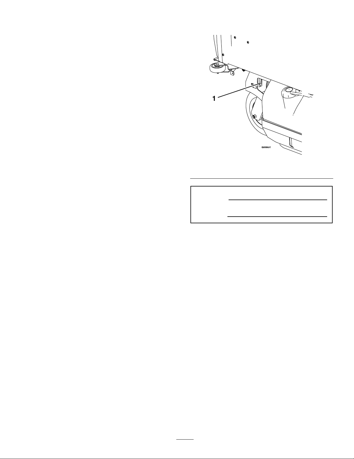
Figure1
1.Modelandserialnumberlocation
ModelNo.
SerialNo.
Figure1identiesthelocationofthemodelandserial
numbersontheproduct.Writethenumbersinthe
spaceprovided.
3
Page 4

Contents
Introduction...........................................................3
Safety.....................................................................5
SafetyAlertSymbol.........................................5
SafeOperatingPractices..................................5
SafetyandInstructionalDecals.....................11
Specications.......................................................14
ModelNumbers............................................14
Systems.........................................................14
Dimensions...................................................15
TorqueRequirements....................................16
ProductOverview................................................16
Operation.............................................................17
Controls........................................................17
Pre-Start........................................................18
OperatingInstructions..................................18
Transporting.................................................20
Maintenance.........................................................22
RecommendedMaintenanceSchedule(s)...........22
PeriodicMaintenance.......................................23
CheckEngineOilLevel.................................23
CheckBatteryCharge....................................23
CheckSafetyInterlockSystem.......................24
CheckforLooseHardware............................25
ServiceAirCleaner........................................25
ChangeEngineOil........................................25
CheckHydraulicOilLevel.............................26
CheckTirePressures.....................................26
CheckConditionOfBelts..............................26
LubricateGreaseFittings...............................26
LubricateRearCasterWheelHubs.................27
LubricateBrakeHandlePivot........................28
LubricateBrakeRodBushings.......................28
LubricateSteeringLinkageRodEnds.............28
LubricateHopperActuator............................28
CheckSparkPlugs.........................................28
ChangeHydraulicSystemFilter.....................29
CheckWheelHubLocknuts..........................29
CheckWheelLugNuts..................................29
ThreadLockingAdhesives.............................29
DielectricGrease...........................................30
Adjustments.....................................................30
PTODriveBeltTension................................30
PumpDriveBeltTension...............................30
PTOBeltReplacement..................................30
PumpDriveBeltReplacement......................31
BeltGuideAdjustment..................................31
AdjustSafetySwitch......................................32
BrakeAdjustment..........................................32
AdjustSpeedControlLeverTension..............32
SpeedControlLinkageAdjustment................33
SteeringControlLeverResponse
Adjustment...............................................34
TrackingAdjustment.....................................35
PTODrivePulleyAlignment.........................35
PumpDrivePulleyAlignment........................35
RearCasterPivotBearingsPre-Load
Adjustment...............................................36
HopperDoorAdjustment.............................36
PTOBrakeSpringAdjustment......................36
Cleaning...........................................................37
CleanEngineandExhaustSystem
Area..........................................................37
RemoveEngineShroudsandCleanCooling
Fins...........................................................37
CleanDebrisFromMachine..........................37
WasteDisposal..............................................37
Troubleshooting...................................................38
Schematics...........................................................40
4
Page 5

Safety
Safety
SafetyAlertSymbol
ThisSafetyAlertSymbol(Figure2)isusedbothin
thismanualandonthemachinetoidentifyimportant
safetymessageswhichmustbefollowedtoavoid
accidents
Thissymbolmeans:ATTENTION!BECOME
ALERT!YOURSAFETYISINVOLVED!
Figure2
1.Safetyalertsymbol
Thesafetyalertsymbolappearsaboveinformation
whichalertsyoutounsafeactionsorsituations
andwillbefollowedbythewordDANGER,
WARNING,orCAUTION.
DANGER:Whitelettering/Redbackground.
Indicatesanimminentlyhazardoussituationwhich,if
notavoided,Willresultindeathorseriousinjury.
WARNING:Blacklettering/Orangebackground.
Indicatesapotentiallyhazardoussituationwhich,if
notavoided,Couldresultindeathorseriousinjury.
CAUTION:Blacklettering/Yellowbackground.
Indicatesapotentiallyhazardoussituationwhich,if
notavoided,Mayresultinminorormoderateinjury.
Thismanualusestwootherwordstohighlight
information.Importantcallsattentiontospecial
mechanicalinformationandNoteemphasizes
generalinformationworthyofspecialattention.
•Neverletchildrenoruntrainedpeopleoperate
orservicetheequipment.Localregulationsmay
restricttheageoftheoperator.
•Onlyadultsandmatureteenagersshouldoperate
amower,andevenmatureteenagersshouldhave
adultsupervision.Besureateenager:
1.hasreadandunderstandstheOperator’s
Manualandrecognizestherisksinvolved;
2.issufcientlymaturetousecaution;and
3.isofsufcientsizeandweighttooperate
thecontrolscomfortablyandtomanagethe
mowerwithouttakingrisks.
•Theowner/usercanpreventandisresponsible
foraccidentsorinjuriesoccurringtohimselfor
herself,otherpeopleorproperty.
Preparation
•Evaluatetheterraintodeterminewhataccessories
andattachmentsareneededtoproperlyand
safelyperformthejob.Onlyuseaccessoriesand
attachmentsapprovedbyExmark.
•Wearappropriateclothingincludingsafetyglasses,
substantialfootwear,longtrousers,andhearing
protection.DoNotoperatewhenbarefootor
whenwearingopensandals.Longhair,loose
clothingorjewelrymaygettangledinmoving
parts.
CAUTION
Thismachineproducessoundlevelsin
excessof85dBAattheoperator’searand
cancausehearinglossthroughextended
periodsofexposure.
SafeOperatingPractices
Training
•ReadtheOperator’sManualandothertraining
material.Iftheoperator(s)ormechanic(s)can
notreadEnglishitistheowner’sresponsibilityto
explainthismaterialtothem.
•Becomefamiliarwiththesafeoperationofthe
equipment,operatorcontrols,andsafetysigns.
•Alloperatorsandmechanicsshouldbetrained.
Theownerisresponsiblefortrainingtheusers.
Wearhearingprotectionwhenoperatingthis
machine.
•Inspecttheareawheretheequipmentistobe
usedandremoveallrocks,toys,sticks,wires,
bones,andotherforeignobjectswhichcanbe
thrownbythemachineandmaycausepersonal
injurytotheoperatororbystanders.
5
Page 6

Safety
DANGER
Incertainconditionsgasolineisextremely
ammableandvaporsareexplosive.
Areorexplosionfromgasolinecanburn
you,others,andcausepropertydamage.
•Fillthefueltankoutdoorsonlevel
ground,inanopenarea,whentheengine
iscold.Wipeupanygasolinethatspills.
•Neverrellthefueltankordrainthe
machineindoorsorinsideanenclosed
trailer.
•DoNotllthefueltankcompletelyfull.
Fillthefueltanktothebottomoftheller
neck.Theemptyspaceinthetankallows
gasolinetoexpand.Overllingmayresult
infuelleakageordamagetotheengine
oremissionsystem(ifequipped).
•Neversmokewhenhandlinggasoline,
andstayawayfromanopenameor
wheregasolinefumesmaybeignitedby
spark.
•Storegasolineinanapprovedcontainer
andkeepitoutofthereachofchildren.
•Addfuelbeforestartingtheengine.
Neverremovethecapofthefueltankor
addfuelwhenengineisrunningorwhen
theengineishot.
•Iffuelisspilled,DoNotattempttostart
theengine.Moveawayfromtheareaof
thespillandavoidcreatinganysourceof
ignitionuntilfuelvaporshavedissipated.
•DoNotoperatewithoutentireexhaust
systeminplaceandinproperworking
condition.
DANGER
Incertainconditionsduringfueling,static
electricitycanbereleasedcausingaspark
whichcanignitegasolinevapors.Areor
explosionfromgasolinecanburnyouand
othersandcausepropertydamage.
•Alwaysplacegasolinecontainersonthe
groundawayfromyourvehiclebefore
lling.
•DoNotllgasolinecontainersinsidea
vehicleoronatruckortrailerbedbecause
interiorcarpetsorplastictruckbedliners
mayinsulatethecontainerandslowthe
lossofanystaticcharge.
•Whenpractical,removegas-powered
equipmentfromthetruckortrailerand
refueltheequipmentwithitswheelson
theground.
•Ifthisisnotpossible,thenrefuelsuch
equipmentonatruckortrailerfroma
portablecontainer,ratherthanfroma
gasolinedispensernozzle.
•Ifagasolinedispensernozzlemustbe
used,keepthenozzleincontactwiththe
rimofthefueltankorcontaineropening
atalltimesuntilfuelingiscomplete.
WARNING
Gasolineisharmfulorfatalifswallowed.
Long-termexposuretovaporshascaused
cancerinlaboratoryanimals.Failuretouse
cautionmaycauseseriousinjuryorillness.
•Avoidprolongedbreathingofvapors.
•Keepfaceawayfromnozzleandgas
tank/containeropening.
•Keepawayfromeyesandskin.
•Neversiphonbymouth.
6
Page 7

Safety
•Checkthattheoperator’spresencecontrols,
safetyswitches,andshieldsareattachedand
functioningproperly.DoNotoperateunlessthey
arefunctioningproperly.
Operation
WARNING
Operatingengineparts,especiallythe
mufer,becomeextremelyhot.Severeburns
canoccuroncontactanddebris,suchas
leaves,grass,brush,etc.cancatchre.
•Allowengineparts,especiallythemufer,
tocoolbeforetouching.
•Removeaccumulateddebrisfrommufer
andenginearea.
•Installandmaintaininworkingordera
sparkarresterbeforeusingequipment
onforest-covered,grass-covered,or
brush-coveredunimprovedland.
WARNING
OperatingaNavigatortractorwithoutan
approvedExmarkfrontmountattachment
increasesthepossibilityofoperator
entanglementindrivewheelsorforwardtip
over.Entanglementortip-overcouldcause
seriousinjuryordeath.
WhenoperatingaNavigatortractor
withoutanapprovedExmarkfrontmount
attachment,observethefollowing:
•Keepfeetandclothingawayfromtires.
•Limitoperationtominimumrequiredto
installadifferentfrontmountattachment.
•Minimizespeedanduseextremecaution.
•Onlyoperateonaatlevelsurface.
•Donotoperateupordownatrailerramp.
•Avoidsuddenaccelerationordeceleration.
•Operateonlyindaylightorgoodarticiallight,
keepingawayfromholesandhiddenhazards.
WARNING
Engineexhaustcontainscarbonmonoxide,
whichisanodorlessdeadlypoisonthatcan
killyou.
DoNotrunengineindoorsorinasmall
connedareawheredangerouscarbon
monoxidefumescancollect.
•Besurealldrivesareinneutralandparkingbrake
isengagedbeforestartingengine.
•Neverraisedeckwithbladesrunning.
•Neveroperatethemowerwithdamagedguards,
shields,orcovers.Alwayshavesafetyshields,
guards,switchesandotherdevicesinplaceandin
properworkingcondition.
•Nevermowunlessthereisagrasscollection
systemormulchkitinplaceandworkingproperly .
•DoNotchangetheenginegovernorsettingor
overspeedtheengine.
•Stopengine,waitforallmovingpartstostop,
removekeyandengageparkingbrake:
–Beforechecking,cleaningorworkingonthe
mower.
–Afterstrikingaforeignobjectorabnormal
vibrationoccurs(inspectthemowerfor
damageandmakerepairsbeforerestarting
andoperatingthemower).
–Beforeclearingblockages.
–Wheneveryouleavethemower.
7
Page 8
Safety
•Stopengine,waitforallmovingpartstostop,and
engageparkingbrake:
–Beforerefueling.
–Beforedumpingthegrasscatcher.
WARNING
Hands,feet,hair,clothing,oraccessoriescan
becomeentangledinrotatingparts.Contact
withtherotatingpartscancausetraumatic
amputationorseverelacerations.
•DoNotoperatethemachinewithout
guards,shields,andsafetydevicesin
placeandworkingproperly.
•Keephands,feet,hair,jewelry,orclothing
awayfromrotatingparts.
•NEVERcarrypassengers.DONOToperate
themowerwhenpeople,especiallychildren,or
petsareinthearea.
•Bealert,slowdownandusecautionwhenmaking
turns.Lookbehindandtothesidebefore
changingdirections.
DANGER
Operatingonwetgrassorsteepslopescan
causeslidingandlossofcontrol.Wheels
droppingoveredges,ditches,steepbanks,or
watercancauserollovers,whichmayresult
inseriousinjury,deathordrowning.
•DoNotmowslopeswhengrassiswet.
•DoNotmowneardrop-offsornearwater.
•DoNotmowslopesgreaterthan15
degrees.
•Reducespeedanduseextremecaution
onslopes.
•Avoidsuddenturnsorrapidspeed
changes.
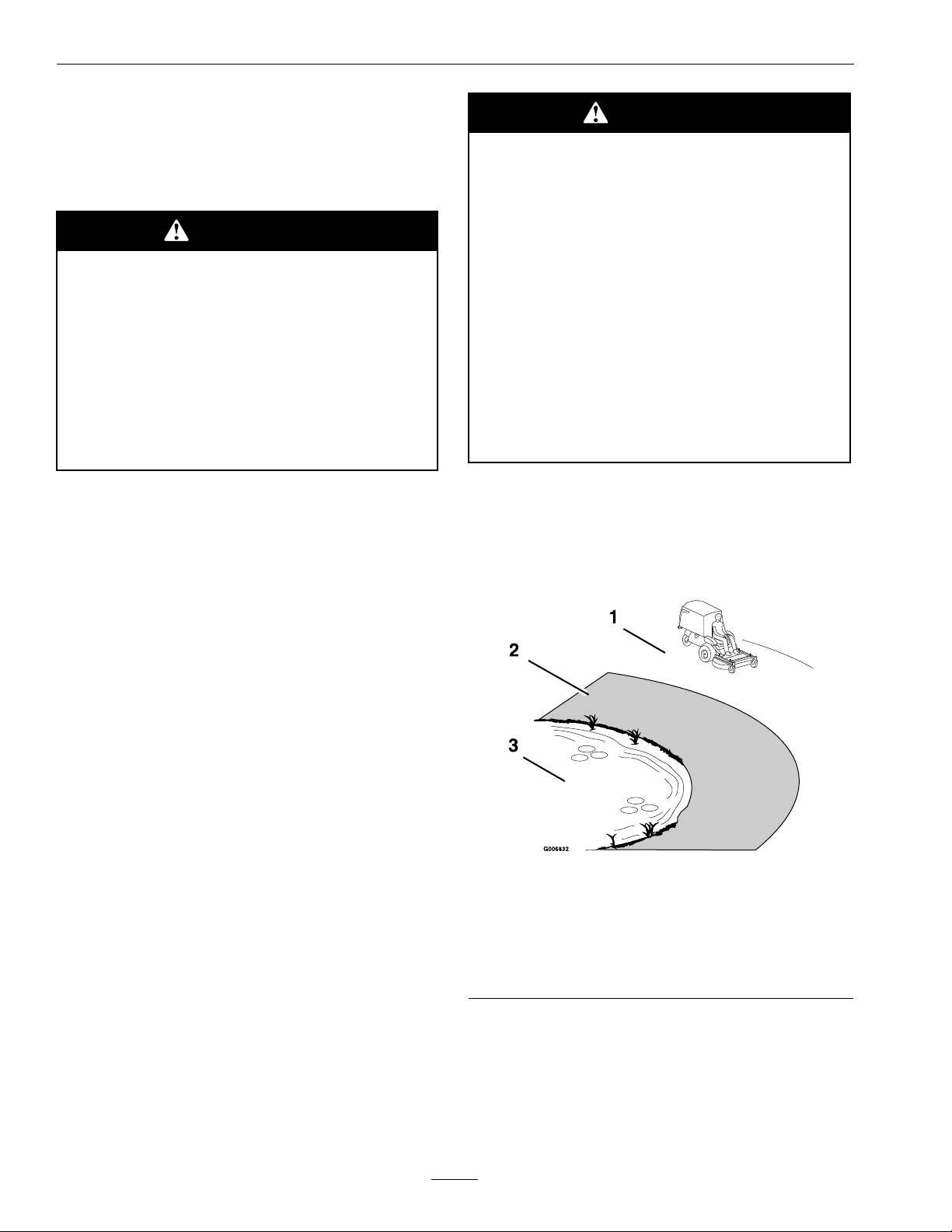
•Seeinsidethebackcovertodeterminethe
approximateslopeangleoftheareatobemowed.
•Useawalkbehindmowerand/orahandtrimmer
neardrop-offs,ditches,steepbanksorwater.
(Figure3).
•Stoptheblades,slowdown,andusecautionwhen
crossingsurfacesotherthangrassandwhen
transportingthemowertoandfromtheareato
bemowed.
•Beawareofthemowerdischargepathanddirect
dischargeawayfromothers.
•DoNotoperatethemowerundertheinuence
ofalcoholordrugs.
•Useextremecarewhenloadingorunloadingthe
machineintoatrailerortruck.
•Usecarewhenapproachingblindcorners,shrubs,
trees,orotherobjectsthatmayobscurevision.
SlopeOperation
UseExtremecautionwhenmowingand/orturning
onslopesaslossoftractionand/ortip-overcould
occur.Theoperatorisresponsibleforsafeoperation
onslopes.
Figure3
1.SafeZone-Usethemowerhereonslopeslessthan15
degrees
2.DangerZone-Useawalkbehindmowerand/orhand
trimmeronslopesgreaterthan15degrees,near
drop-offsandwater.
3.Water
•Removeormarkobstaclessuchasrocks,tree
limbs,etc.fromthemowingarea.Tallgrasscan
hideobstacles.
•Watchforditches,holes,rocks,dipsandrisesthat
changetheoperatingangle,asroughterraincould
overturnthemachine.
8
Page 9

Safety
•Avoidsuddenstartswhenmowingdownhill.
Mowermaytipforwards.
•Beawarethatoperatingonwetgrass,acrosssteep
slopesordownhillmaycausethemowertolose
traction.Lossoftractiontothedrivewheelsmay
resultinslidingandalossofbrakingandsteering.
•Alwaysavoidsuddenstartingorstoppingona
slope.Iftireslosetraction,disengagetheblades
andproceedslowlyofftheslope.
•Followthemanufacturer’srecommendationsfor
wheelweightsorcounterweightstoimprove
stability.
•Useextremecarewithattachments.Thesecan
changethestabilityofthemachineandcauseloss
ofcontrol.
Note:A2–postfoldableROPS(RolloverProtection
System)isavailablefortheNavigatorasanaccessory.
AROPSisrecommendedifyouwillbemowing
nexttodrop-offs,nearwater,oronsteepbanks
whichcouldresultinarollover.Themodelnumber
fortheROPSattachmentisFRPSNAV .Contactan
AuthorizedExmarkServiceDealerformoredetails.
•Disconnectbatteryorremovesparkplugwire
beforemakinganyrepairs.Disconnectthe
negativeterminalrstandthepositivelast.
Reconnectpositiverstandnegativelast.
•Usecarewhencheckingblades.Wraptheblade(s)
orweargloves,andusecautionwhenservicing
them.Onlyreplacedamagedblades.Never
straightenorweldthem.
•Keephandsandfeetawayfrommovingparts.
Ifpossible,donotmakeadjustmentswiththe
enginerunning.
•Chargebatteriesinanopenwellventilatedarea,
awayfromsparkandames.Unplugcharger
beforeconnectingordisconnectingfrombattery.
Wearprotectiveclothinganduseinsulatedtools.
DANGER
Chargingorjumpstartingthebatterymay
produceexplosivegases.Batterygasescan
explodecausingseriousinjury.
•Keepsparks,ames,orcigarettesaway
frombattery.
MaintenanceandStorage
•Disengagedrives,lowerimplement,setparking
brake,stopengineandremovekeyordisconnect
sparkplugwire.Waitforallmovementtostop
beforeadjusting,cleaningorrepairing.
•Keepengine,enginearea,andpumpdrivebelt
compartmentfreefromaccumulationofgrass,
leaves,excessivegreaseoroil,andotherdebris
whichcanaccumulateintheseareas.These
materialscanbecomecombustibleandmayresult
inare.
•Letenginecoolbeforestoringanddonotstore
nearameoranyenclosedareawhereopenpilot
lightsorheatappliancesarepresent.
•Shutofffuelwhilestoringortransporting.Do
Notstorefuelnearamesordrainindoors.
•Parkmachineonlevelground.Neverallow
untrainedpersonneltoservicemachine.
•Usejackstandstosupportcomponentswhen
required.
•Ventilatewhenchargingorusingbattery
inanenclosedspace.
•Makesureventingpathofbatteryis
alwaysopenoncebatteryislledwith
acid.
•Alwaysshieldeyesandfacefrombattery.
DANGER
Batteryelectrolytecontainssulfuricacid,
whichispoisonousandcancausesevere
burns.Swallowingelectrolytecanbefatalor
ifittouchesskincancausesevereburns.
•Wearsafetyglassestoshieldeyes,and
rubberglovestoprotectskinandclothing
whenhandlingelectrolyte.
•DoNotswallowelectrolyte.
•Intheeventofanaccident,ushwith
waterandcalladoctorimmediately .
•Carefullyreleasepressurefromcomponentswith
storedenergy.
9
Page 10

Safety
CAUTION
Iftheignitionisinthe“ON”positionthere
ispotentialforsparksandengagement
ofcomponents.Sparkscouldcausean
explosionormovingpartscouldaccidentally
engagecausingpersonalinjury
Besureignitionswitchisinthe“OFF”
positionbeforechargingthebattery.
•Keepallguards,shieldsandallsafetydevicesin
placeandinsafeworkingcondition.
•Checkallboltsfrequentlytomaintainproper
tightness.
•Frequentlycheckforwornordeteriorating
componentsthatcouldcreateahazard.
WARNING
Removingstandardoriginalequipment
parts,orusingnon-Exmarkreplacement
partsandaccessoriesmayalterthewarranty,
traction,andsafetyofthemachine.Failure
touseoriginalExmarkpartscouldcause
seriousinjuryordeath.
WARNING
Hydraulicuidescapingunderpressure
canpenetrateskinandcauseinjury.Fluid
accidentallyinjectedintotheskinmustbe
surgicallyremovedwithinafewhoursbya
doctorfamiliarwiththisformofinjuryor
gangrenemayresult.
•Makesureallhydraulicuidhoses
andlinesareingoodconditionand
allhydraulicconnectionsandttings
aretightbeforeapplyingpressureto
hydraulicsystem.
•Keepbodyandhandsawayfrompinhole
leaksornozzlesthatejecthighpressure
hydraulicuid.
•Usecardboardorpaper,notyourhands,
tondhydraulicleaks.
•Safelyrelieveallpressureinthehydraulic
systembyplacingthemotioncontrol
leversinneutralandshuttingoffthe
enginebeforeperforminganyworkon
thehydraulicsystem.
Replaceallpartsincluding,butnotlimited
to,tires,belts,andbladeswithoriginal
Exmarkparts.
10
Page 11
SafetyandInstructionalDecals
Safety
•Keepallsafetysignslegible.Removeallgrease,
dirtanddebrisfromsafetysignsandinstructional
labels.
•Replaceallworn,damaged,ormissingsafety
signs.
•Whenreplacementcomponentsareinstalled,be
surethatcurrentsafetysignsareafxedtothe
replacedcomponents.
•Ifanattachmentoraccessoryhasbeeninstalled,
makesurecurrentsafetysignsarevisible.
1-513747
•Newsafetysignsmaybeobtainedfrom
yourauthorizedExmarkequipmentdealeror
distributororfromExmarkMfg.Co.Inc.
•Safetysignsmaybeafxedbypeelingoffthe
backingtoexposetheadhesivesurface.Apply
onlytoaclean,drysurface.Smoothtoremove
anyairbubbles.
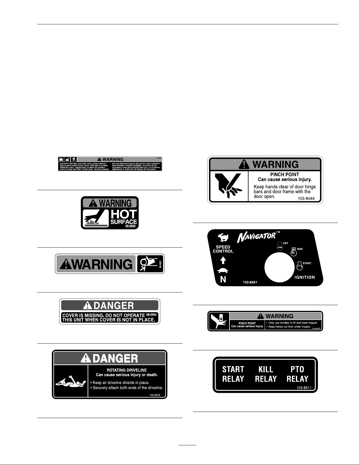
•Familiarizeyourselfwiththefollowingsafetysigns
andinstructionlabels.Theyarecriticaltothesafe
operationofyourExmarkcommercialmower.
103-8444
65-2690
98-4361
103-8451
98-5954
103-8495
103-8611
103-8425
11
Page 12
Safety
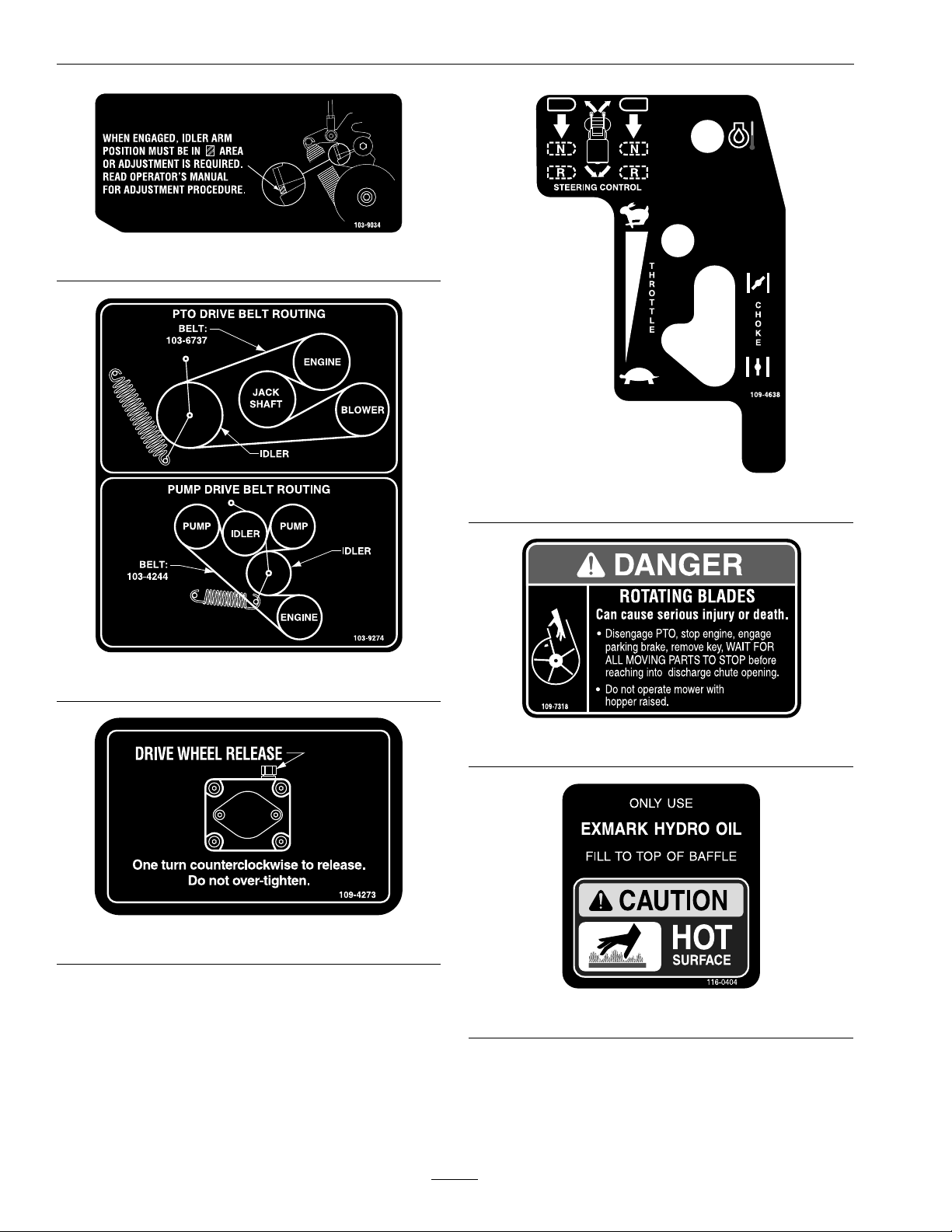
103-9034
109-4638
103-9724
109-7318
109-4273
116-0404
12
Page 13
Safety
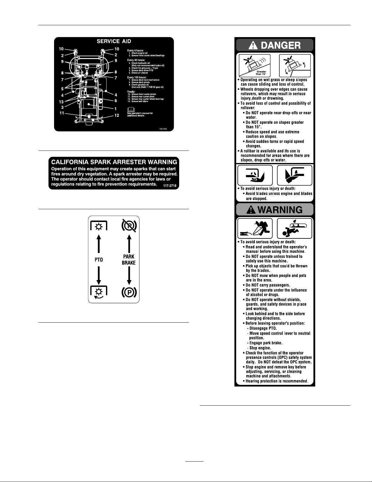
116-1175
117–2718
MoldedinLHConsole
MoldedintoFrontofHopper
13
Page 14

Specications
Specications
ModelNumbers
SerialNos:850,000andHigher
NAV20KC;NAV27KC
Systems
Engine
•EngineSpecications:SeeyourEngineOwner’s
Manual
•RPM:FullSpeed:3600±50RPM(NoLoad)
Idle:1500RPM
FuelSystem
•Capacity:7.5gal.(28L)
•TypeofFuel:Regularunleadedgasoline,87
octaneorhigher;containingnomorethan10%
methanolorethanol.
•FuelFilter:In-line30MicronKohlerP/N
2405010.
•FuelShut-OffValve:1/4turnincrementsin-line
valvebyfuellter.
ElectricalSystem
•ChargingSystem:FlywheelAlternator
•ChargingCapacity:15amps
•BatteryType:BCIGroupU1
•BatteryVoltage:12Volt
•Polarity:NegativeGround
•Fuses:Two20ampandone30ampbladetype
•SafetyInterlockSystem:
–PTOmustbedisengaged,brakeengaged,and
speedcontrolleverinneutralpositiontostart
engine.(Itisnotnecessaryfortheoperatorto
beintheseattostarttheengine.)
–OperatormustbeinseatwhenPTOis
engaged,brakeisdisengaged,orspeedcontrol
leverismovedoutofneutralorenginewill
stop.
–Enginewillstopinthefollowingconditions:
◊Ifthespeedcontrolleverismovedfrom
neutralpositionwhilebrakeisengaged.
◊IfthePTOisengagedwhilethehopper
istiltedup.
OperatorControls
•SteeringandMotionControl:
–SpeedControllever,locatedonRHconsole,
setsmaximumforwardspeed.
–Steeringlevers,centeredinfrontoftheseat,
controlthespeedanddirectionoftravelof
therespectivedrivewheels.
–Movingspeedcontrolleverrearwardtothe
neutralpositionplacesthedrivesystemin
neutral.
Note:Theunitmaybemovedinreverse
whilethespeedcontrolisintheneutral
positionbypullingbackonthesteeringlevers.
•PTOEngagementLever:EngagesdrivetoPTO
(mowerdeck)andblower.
•ParkingBrakeLever:Pullbacktoengageparking
brake.
Seat
•Type:Standardseatwithhighback,foampadded
(internalsuspension).
•Mounting:Seatishingedtotiltupforaccessto
hydraulicpumpsandothercomponents.Theseat
isheldinthetiltedpositionwithalink.
•Armrests:None.
•SeatSafetySwitch:Internaltothebottomseat
cushion,nonserviceable.Timedelaymodule
incorporatedintotheSafetyInterlockSystem
eliminatesroughgroundcut-outs.
HydrostaticGroundDriveSystem
•HydrostaticPumps:TwoHydroGearvariable
displacementpistonpumps.
•WheelMotors:HydroGearplanetaryreduction
motors.
14
Page 15

Specications
•HydraulicOilType:UseExmarkPremiumHydro
oil.
•HydraulicOilCapacity:4.0qt.(3.8L)
•HydraulicFilter:Replaceablecartridgetype.
–Summeruseabove32°F(0°C):
P/N109-0071:25microns,10psibypass
–Winterusebelow32°F(0°C):
P/N1-523541:40microns,18psibypass
•Speeds:
–0-7.0mph(11.3km/hr)forward.
–0-5.5mph(8.6km/hr)reverse.
•Drivewheelreleasevalvesallowmachinetobe
movedwhenengineisnotrunning.
Tires&Wheels
Drive
Pneumatic
(Air-Filled)
Quantity
221
Front
Caster
SemiPneumatic
RearCaster
SemiPneumatic
–Clutchingbeltonhorizontalengineshaft.
Dual“ A ”sectionhexagonbeltwithspring
tensionedidlertojackshaftandblower.
–Heavy-dutycastiron,spiralbevelgearboxis
naldrivetoblades.
•Deck:
Fulloatingdeckisattachedtoout-frontsupport
frame.Deckdesignallowsforbaggingor
mulching.
•DeckDepth:
–42inchDeck:45/8inches(11.7cm)
–48inchDeck:45/8inches(11.7cm)
Dimensions
OverallWidth:
WithoutDeck42inchDeck48inchDeck
42.6inches
(108.2cm)
43.2inches
(109.7cm)
49.2inches
(125.0cm)
Tread
Size
PlyRating
Pressure
“Multi-Trac
C/S”
18x
10.50-10
4
15psi(103
kPa)
SmoothSmooth
8x3.00-413x8.00-6
CuttingDeck
(Soldseparately)
•ModelNumbers:
–CD42CD
–CD48CD
•CuttingWidth:
–42inchDeck:42inch(106.7cm)
–48inchDeck:48inch(121.9cm)
•Discharge:Center
•BladeSize:(2ea.)
–w/42inchDeck:22.00inches(55.9cm)
–w/48inchDeck:25.00inches(63.5cm)
•DeckDrive:
OverallLength:
WithoutDeck42inchDeck48inchDeck
67.3inches
(170.9cm)
91.8inches
(233.2cm)
94.5inches
(240.0cm)
OverallHeight:
WithoutDeck42inchDeck48inchDeck
51.2inches
(130.0cm)
51.2inches
(130.0cm)
51.2inches
(130.0cm)
TreadWidth:(CentertoCenterof
Tires,Widthwise)
42inchDeck48inchDeck
DriveWheels32.7inches
(83.1cm)
32.7inches
(83.1cm)
WheelBase:(CenterofDriveWheel
toCenterofRearCasterWheel)
42inchDeck48inchDeck
44.2inches(112.3cm)44.2inches(112.3cm)
15
Page 16

ProductOverview
CurbWeight:
42inchDeck48inchDeck
850lb(386kg)1145lb(519kg)
TorqueRequirements
BoltLocation
BladeMountingBolt85-110ft-lb(115-149N-m)
EngineMountingBolts
WheelLugNuts
WheelMotorMounting
Bolts
WheelHubLocknut210-250ft-lb
Torque
30-35ft-lb(41-47N-m)
90-95ft-lb(122-129N-m)
72-77ft-lb(98-104N-m)
(285-339N-m)
ProductOverview
Figure4
1.SpeedControlLever4.SteeringLevers
2.Controls5.PTOEngagementLever
3.FuelCap
6.ParkingBrakeLever
16
Page 17

Operation
Operation
Note:Determinetheleftandrightsidesofthe
machinefromthenormaloperatingposition.
Controls
SteeringLevers
Locatedinthecenterinfrontoftheseat.
Pullingbackonthesteeringlevers,progressively
slows,thenreversesthedirectionoftravelofthe
respectivedrivewheels.
Bymovingbothsteeringleversanequalamountback,
themachinecanbesloweddownortravelbackward
inastraightline.
Steeringiscontrolledbyvaryingthepositionofthe
steeringleversrelativetoeachother.
SpeedControlLever
Locatedonrighthandconsole.
Thespeedcontrolleversetsmaximumforwardspeed.
Movingspeedcontrolleverrearwardtotheneutral
positionplacesthedrivesysteminneutral.
BrakeLever
Locatedonleftsideofunit,betweentheseatand
console.
Thebrakeleverengagesaparkingbrakeonthedrive
wheels.
Pulltheleverupandrearwardtoengagethebrake.
Pushtheleverforwardanddowntodisengagethe
brake.
Theunitmustbetieddownandbrakeengagedwhen
transporting.
IgnitionSwitch
Locatedontherighthandconsole.
Theignitionswitchisusedtostartandstopthe
engine.Theswitchhasthreepositions“OFF”,“ON”
and“START”.Insertkeyintoswitchandrotate
clockwisetothe“ON”position.Rotateclockwiseto
thenextpositiontoengagethestarter(keymustbe
heldagainstspringpressureinthisposition).
Note:Brakemustbeengaged,speedcontrollever
rearward(neutralposition)andPTOdisengagedto
startengine.(Itisnotnecessaryfortheoperatorto
beintheseattostarttheengine.)
HourMeter
ChokeControl
Locatedonrighthandconsole.
Thechokeisusedtoaidinstartingacoldengine.
Movingthechokeleverforwardwillputthechokein
the“ON”positionandmovingthechokelevertothe
rearwillputthechokeinthe“OFF”position.DO
NOTrunawarmenginewithchokeinthe“ON”
position.
ThrottleControl
Locatedonrighthandconsole.
Thethrottleisusedtocontrolenginespeed.Moving
throttleleverforwardwillincreaseenginespeedand
movingthrottlelevertotherearwilldecreaseengine
speed.
Locatedontherighthandconsole.
Thehourmeterisconnectedtoapressureswitch
installedintheengineblockanditrecordsthe
numberofhoursthattheenginehasrun.Ifthe
ignitionswitchisleftonwithoutenginerunning,
hourmeterwillnotrun.
Note:Thisswitchisnotalowoilsensorandwillnot
alerttheoperatoriftheengineoilislow .
FuelShut-OffValve
Locatedinfuellinebyfueltankandfuellter
(accessiblebyraisingthehopper).
Thefuelshut-offvalveisusedtoshutoffthefuel
whenthemachinewillnotbeusedforafewdays,
duringtransporttoandfromthejobsite,andwhen
parkedinsideabuilding.
Rotatethevalve1/4turnclockwisetoshutoffthe
fuel.rotatethevalve1/4turncounterclockwiseto
turnonthefuel.
17
Page 18

Operation
DriveWheelReleaseValves
Locatedonthetopleftfrontcornerofhydrostatic
pumps.
Drivewheelreleasevalvesareusedtoreleasethe
hydrostaticdrivesystemtoallowthemachinetobe
pushedwithouttheenginerunning.Tiltseatupto
gainaccesstopumps.
Witha7/16wrench,turnbothvalvesoneturn
counterclockwisetoreleasedrivesystem.Turn
clockwisetoresetsystem.DoNotovertighten.Do
Nottowmachine.
TrackingAdjustmentKnob
Locatedundertheseatontheleftpumpcontrollink.
Rotatingthisknoballowsnetuningadjustmentsso
thatthemachinetracksstraightwiththedrivelevers
inthefullforwardposition.
Rununitat3/4speedforatleast5minutesto
bringhydraulicoiluptooperatingtemperature.
Stopmachineandwaitforallmovingpartstostop.
Engageparkbrake.Tiltseatforwardtogainaccess
tothetrackingknob.Rotatetheknobtowardsthe
righttosteerrightandrotatetowardstheleftto
steerleft.Adjustin1/8turnincrementsuntilthe
machinetracksstraight.Checkthatthemachine
doesnotcreepwheninneutralwiththeparkbrakes
disengaged.
Important:DoNotrotatetheknobtoofar,as
thismaycausethemachinetocreepinneutral.
RefertotheMotionControlLinkageAdjustment
sectioninMaintenance.
PTOEngagementLever
Locatedimmediatelyleftoftheleftconsole.
Levermustbemoveduptothe“ROTATE”position
toengagethePTOandblowerdrives.Leverismoved
downtothe“STOP”positiontostopthedrives.
EngineOilTemperatureLightand
Buzzer
Locatedontherightconsole.
Theengineoiltemperaturelightmonitorsthe
temperatureoftheengineoil.Anilluminatedengine
oiltemperaturelightandintermittentbuzzingsound
signalstheengineisoverheating.
Pre-Start
Fillfueltanks.Forbestresultsuseonlyclean,fresh
regulargradeunleadedgasolinewithanoctanerating
of87orhigher.
Important:Neverusemethanol,gasoline
containingmethanol,gasoholcontainingmore
than10%ethanol,premiumgasoline,orwhite
gasbecausethefuelsystemcouldbedamaged.
DoNotaddoiltogasoline.
DoNotoverllfueltank.Fillthefueltanktothe
bottomofthellerneck.Theemptyspaceinthe
tankallowsgasolinetoexpand.Overllingmayresult
infuelleakageordamagetotheengineoremission
system(ifequipped).
Makesureyouunderstandthecontrols,their
locations,theirfunctions,andtheirsafety
requirements.
RefertotheMaintenancesectionandperformallthe
necessaryinspectionandmaintenancesteps.
OperatingInstructions
OpentheFuelShut-OffValve
Thefuelshut-offvalveislocatedontherightsideof
unitinfuellinenexttothefuellter.Raisethehopper
toaccess.Rotatethevalve1/4counterclockwiseto
turnonfuel.
StartingtheEngine
1.Movethespeedcontrollevertotheneutral
position.
2.Pullupandbackontheparkingbrakeleverto
engagetheparkingbrake.
3.PushthePTOengagementleverdowntothe
“STOP”position.
Note:Itisnotnecessaryfortheoperatortobe
intheseattostarttheengine.
4.Placethethrottlemidwaybetweenthe“SLOW”
and“FAST”positions.
5.Onacoldengine,pushthechokeleverforward
intothe“ON”position.
Onawarmengine,leavethechokeinthe“OFF”
position.
18
Page 19

Operation
6.Turnignitionswitchtothe“START”position.
Releasetheswitchassoonastheenginestarts.
Important:DoNotcranktheengine
continuouslyformorethantensecondsata
time.Iftheenginedoesnotstart,allowa60
secondcool-downperiodbetweenstarting
attempts.Failuretofollowtheseguidelines
canburnoutthestartermotor.
7.Ifthechokeisinthe“ON”position,gradually
returnchoketothe“OFF”positionastheengine
warmsup.
EngagingthePTO
DANGER
Therotatingbladesunderthemowerdeck
aredangerous.Bladecontactcancause
seriousinjuryorkillyou.
DoNotputhandsorfeetunderthemower
ormowerdeckwhenthebladesareengaged.
DisengagingthePTO
1.Setthethrottletothe“MIDWAY”position.
2.PushPTOleverdowntothe“STOP”position
stoppingthePTOandblower.
StoppingtheEngine
1.Bringtheunittoafullstop.
2.DisengagethePTO.
3.Movespeedcontrollevertotheneutralposition.
4.Engagetheparkingbrake.
5.Placethethrottlemidwaybetweenthe“SLOW”
and“FAST”positions.
6.Allowtheenginetorunforaminimumof15
seconds,thenturntheignitionswitchtothe
“OFF”positiontostoptheengine.
7.Removethekeytopreventchildrenorother
unauthorizedpersonsfromstartingengine.
8.Closethefuelshut-offvalvewhenthemachine
willnotbeinuseforafewdays,when
transporting,orwhentheunitisparkedinside
abuilding.
DANGER
Anuncovereddischargeopeningwillallow
objectstobethrowninanoperator’sor
bystander’sdirection.Also,contactwiththe
blowerbladescouldoccur.Thrownobjects
orbladecontactcancauseseriousinjuryor
death.
Neveroperatethemowerwiththehopper
orhopperdoorraised,removed,oraltered
unlessthereisamulchkitinplaceand
workingproperly.
ThePTOleverengagesthePTOandblower.Besure
thatthehopperisdown,thehopperdoorissecurely
closed,andallpersonsareclearofthemowerdeck
anddischargeareabeforeengagingPTO.
Important:Operatormustbeinseatbeforethe
PTOcanbeengaged.
1.Setthethrottletothe“MIDWAY”position.
2.PullthePTOleverupwarduntillockedover
center.
DrivingtheMachine
CAUTION
Machinecanspinveryrapidlybypositioning
onelevertoomuchaheadoftheother.
Operatormaylosecontrolofthemachine,
whichmaycausedamagetothemachine
orinjury.
•Usecautionwhenmakingturns.
•Slowthemachinedownbeforemaking
sharpturns.
Important:Tobeginmovement(forwardor
backward)theoperatormustbeintheseat,the
brakelevermustbedisengaged(pusheddown)
beforethespeedcontrollevercanbemoved
forwardortheenginewillstop.
DrivingForward
1.Starttheengine.
2.Releasetheparkingbrake.
3.Placethethrottleinthe“FAST”positiontobegin
mowing.
3.Tomoveforwardinastraightlinemovethespeed
controlleverforward.
19
Page 20

Operation
Toturnleftorright,pulloneofthesteeringlevers
backtowardneutralinthedirectiondesired.
Themachinewillmovefasterthefartherthe
speedcontrolleverismovedawayfromneutral.
4.Tostop,pullthespeedcontrolleverbacktothe
neutralposition.
DrivinginReverse
1.Tomoverearwardinastraightlineapplyingequal
pressurepullbothsteeringleversrearward.
Toturnleftorright,releasepressureonthe
steeringlevertowardthedirectiondesired.
2.Tostop,releasethesteeringleverstotheneutral
position.
EmptyingHopper
1.Afullhopperisindicatedbyabuzzerlocated
behindtheoperatorinthehopper.Emptyhopper
whenbuzzersoundstopreventcloggingofthe
blowerordeck.
2.DisengagePTO,movespeedcontroltoneutral,
setparkbrakeanddismountunittodumphopper.
3.Makesureunitisonadrylevelsurface.
4.Liftthereardoorupandallowittorestontop
ofhopper.
5.Dumphopperbyrmlygraspingoneofthe
hopperhandlesoneithersideoftheunitand
liftingthehopper.
ClearingHopperScreen
Screenmayberemovedbyrmlyliftingscreen
handles(seeFigure5).
Pullscreentowardsthebacktoremove.Gentlytap
debrisfromthescreenasneeded.
Excessivebuild-uponthescreencancausethe
blowertoplug.
Figure5
1.Frontremovablescreen
canberotatedand
storedforwetcondtions
2.Frontremovablescreen4.Handles.
3.Primaryscreen
Transporting
TransportingaUnit
Useaheavy-dutytrailerortrucktotransportthe
machine.Lockbrakeandblockwheels.Securely
fastenthemachinetothetrailerortruckwithstraps,
chains,cable,orropes.Besurethatthetrailerortruck
hasallnecessarylightingandmarkingasrequiredby
law .Secureatrailerwithasafetychain.
CAUTION
Thisunitdoesnothaveproperturn
signals,lights,reectivemarkings,ora
slowmovingvehicleemblem.Drivingona
streetorroadwaywithoutsuchequipment
isdangerousandcanleadtoaccidents
causingpersonalinjury.Drivingonastreet
orroadwaywithoutsuchequipmentmayalso
beaviolationofStatelawsandtheoperator
maybesubjecttotrafcticketsand/ornes.
DoNotdriveaunitonapublicstreetor
roadway.
Note:Inconditionswherethescreenclogsquickly,
thefrontremovablescreenpanelcanbeturnedand
reinstalledundertheprimaryscreentoallowfreeair
owfromthehopper.
20
Page 21

WARNING
Loadingaunitonatrailerortruckincreases
thepossibilityoftip-over.Tip-overcould
causeseriousinjuryordeath.
•Useextremecautionwhenoperatinga
unitonaramp.
•Useonlyasingle,fullwidthramp;Do
Notuseindividualrampsforeachside
oftheunit.
•Ifindividualrampsmustbeused,use
enoughrampstocreateanunbroken
rampsurfacewiderthantheunit.
•DoNotexceeda15°anglebetweenramp
andgroundorbetweenrampandtrailer
ortruck.
•Avoidsuddenaccelerationwhiledriving
unitonaramp.
Operation
LoadingaUnit
Useextremecautionwhenloadingunitsontrailers
ortrucks.Onefullwidthrampisrequired.Ifitis
notpossibletouseonefullwidthramp,useenough
individualrampstosimulateafullwidthcontinuous
ramp.
Rampshouldbelongenoughsothattheangles
betweentherampandthegroundandtherampand
thetrailerortruckdonotexceed15°.Asteeperangle
maycausemowerdeckcomponentstogetcaughtas
theunitmovesfromramptotrailerortruck.Steeper
anglesmayalsocausetheunittotip.Ifloadingonor
nearaslope,positionthetrailerortrucksoitison
thedownsideoftheslopeandtherampextendsup
theslope.Thiswillminimizetherampangle.The
trailerortruckshouldbeaslevelaspossible.
Important:DoNotattempttoturntheunit
whileontheramp,youmaylosecontroland
driveofftheside.
Avoidsuddenaccelerationwhendrivingonaramp.
21
Page 22

Maintenance
Maintenance
Note:Determinetheleftandrightsidesofthemachinefromthenormaloperatingposition.
WARNING
Whilemaintenanceoradjustmentsarebeing
made,someonecouldstarttheengine.
Accidentalstartingoftheenginecould
seriouslyinjureyouorotherbystanders.
Removethekeyfromtheignitionswitch,
engageparkingbrake,andpullthewire(s)
offthesparkplug(s)beforeyoudoany
maintenance.Alsopushthewire(s)aside
soitdoesnotaccidentallycontactthespark
plug(s).
RecommendedMaintenanceSchedule(s)
MaintenanceService
Interval
Aftertherst5hours
Aftertherst100hours
MaintenanceProcedure
•Changetheengineoil.
•Checkthewheelhublocknutstorquespecication.
•Checkthewheellugnuttorquespecication.
WARNING
Theenginecanbecomeveryhot.T ouching
ahotenginecancausesevereburns.
Allowtheenginetocoolcompletelybefore
serviceormakingrepairsaroundtheengine
area.
Aftertherst250hours
Beforeeachuseordaily
Every40hours
Every50hours
Every80hours
Every100hours
Every160hours
Every500hours
•Changethehydrauliclter.
•Checktheengineoillevel.
•Checkthesafetyinterlocksystem.
•Checkforloosehardware.
•Removeaccumulateddebrisfromengine(seeCleaningsection.)
•Cleanthegrassanddebrisbuild-upfromthemachine.
•Checkthehydraulicoillevel.
•Checkthetirepressures.
•Checktheconditionofthebelts.
•Servicetheaircleaner.(Mayneedmoreoftenundersevereconditions.SeetheEngine
Owner’sManualforadditionalinformation.)
•Removeengineshroudsandcleancoolingns(seeCleaningsection.)
•Changetheengineoil.(Mayneedmoreoftenundersevereconditions.)
•Lubricatethebrakehandlepivot.
•Lubricatethebrakerodbushings.
•Lubricatethesteeringlinkagerodends.
•Lubricatehopperactuator
•Checkthesparkplugs.
•Changethehydrauliclter(Every250hours/yearlyifusingMobil115W50)
•Checkthewheelhublocknutstorquespecication.
•Checkthewheellugnuttorquespecication.
22
Page 23

Maintenance
MaintenanceService
Interval
Monthly
Yearly
MaintenanceProcedure
•Checkthebatterycharge.
•Lubricategreasettings.
•Lubricatethecasterwheelhubs.
PeriodicMaintenance
CheckEngineOilLevel
ServiceInterval:Beforeeachuseordaily
1.Stopengineandwaitforallmovingpartstostop.
Makesureunitisonalevelsurface.
2.Checkwithenginecold.
3.Raisehopper.
4.Cleanareaarounddipstick.Removedipstickand
wipeoiloff.Reinsertthedipstickandpushitall
thewaydownintothetube.Removethedipstick
andreadtheoillevel.
5.Iftheoillevelislow ,wipeofftheareaaroundthe
oilllcap,removecapandlltothe“FULL”
markonthedipstick.Useoilasspeciedin
EngineOwner’ sManual.DoNotoverll.
Important:DoNotoperatetheenginewiththe
oillevelbelowthe“LOW”(or“ADD”)markon
thedipstick,oroverthe“FULL”mark.
CheckBatteryCharge
ServiceInterval:Monthly
WARNING
CALIFORNIA
Proposition65Warning
Batteryposts,terminals,andrelated
accessoriescontainleadandlead
compounds,chemicalsknowntotheStateof
Californiatocausecancerandreproductive
harm.Washhandsafterhandling.
Allowingbatteriestostandforanextendedperiodof
timewithoutrechargingthemwillresultinreduced
performanceandservicelife.T opreserveoptimum
batteryperformanceandlife,rechargebatteriesin
storagewhentheopencircuitvoltagedropsto12.4
volts.
Note:Topreventdamageduetofreezing,battery
shouldbefullychargedbeforeputtingawayfor
winterstorage.
Checkthevoltageofthebatterywithadigital
voltmeter.Locatethevoltagereadingofthebatteryin
thetableandchargethebatteryfortherecommended
timeintervaltobringthechargeuptoafullcharge
of12.6voltsorgreater.
Important:Makesurethenegativebattery
cablesaredisconnectedandthebatterycharger
usedforchargingthebatteryhasanoutputof
16voltsand7ampsorlesstoavoiddamaging
thebattery(seechartforrecommendedcharger
settings).
Voltage
Reading
12.6or
greater
12.4–12.675–100%
12.2–12.450–75%
12.0–12.225–50%
11.7–12.00–25%
11.7orless
Percent
Charge
100%
0%
Maximum
Charger
Settings
16volts/7
amps
16volts/7
amps
16volts/7
amps
14.4volts/4
amps
14.4volts/4
amps
14.4volts/2
amps
Charging
Interval
No
Charging
Required
30Minutes
1Hour
2Hours
3Hours
6Hoursor
More
RecommendedJump
StartingProcedure
ServiceInterval:Asrequired
1.Checktheweakbatteryforterminalcorrosion
(white,green,orblue“snow”),itmustbecleaned
offpriortojumpstarting.Cleanandtighten
connectionsasnecessary.
23
Page 24

Maintenance
CAUTION
Corrosionorlooseconnectionscancause
unwantedelectricalvoltagespikesatanytime
duringthejumpstartingprocedure.
DoNotattempttojumpstartwithlooseor
corrodedbatteryterminalsordamagetothe
enginemayoccur.
DANGER
Jumpstartingaweakbatterythatiscracked,
frozen,haslowelectrolytelevel,oran
open/shortedbatterycell,cancausean
explosionresultinginseriouspersonalinjury.
DoNotjumpstartaweakbatteryifthese
conditionsexist.
2.Makesuretheboosterisagoodandfullycharged
leadacidbatteryat12.6voltsorgreater.Use
properlysizedjumpercables(4to6AWG)with
shortlengthstoreducevoltagedropbetween
systems.Makesurethecablesarecolorcodedor
labeledforthecorrectpolarity .
CAUTION
Note:Besuretheventcapsaretightandlevel.
Placeadampcloth,ifavailable,overanyvent
capsonbothbatteries.Besurethevehiclesdo
nottouchandthatbothelectricalsystemsare
offandatthesameratedsystemvoltage.These
instructionsarefornegativegroundsystemsonly.
3.Connectthepositive(+)cabletothepositive(+)
terminalofthedischargedbatterythatiswiredto
thestarterorsolenoidasshowninFigure6.
Figure6
1.Positive(+)cableondischargedbattery
2.Positive(+)cableonboosterbattery
3.Negative(–)cableontheboosterbattery
4.Negative(–)cableontheengineblock
5.Boosterbattery
6.Dischargedbattery
7.Engineblock
Connectingthejumpercablesincorrectly
(wrongpolarity)canimmediatelydamage
theelectricalsystem.
Becertainofbatteryterminalpolarityand
jumpercablepolaritywhenhookingup
batteries.
Note:Thefollowinginstructionsareadapted
fromtheSAEJ1494Rev.Dec.2001–Battery
BoosterCables–SurfaceVehicleRecommended
Practice(SAE–SocietyofAutomotive
Engineers).
WARNING
Batteriescontainacidandproduceexplosive
gases.
•Shieldtheeyesandfacefromthebatteries
atalltimes.
•DoNotleanoverthebatteries.
4.Connecttheotherendofthepositivecabletothe
positiveterminaloftheboosterbattery.
5.Connecttheblacknegative(–)cabletotheother
terminal(negative)oftheboosterbattery.
6.MAKETHEFINALCONNECTIONON
THEENGINEBLOCKOFTHESTALLED
VEHICLE(NOTTOTHENEGATIVEPOST)
AWAYFROMTHEBATTERY .STANDBACK.
7.Startthevehicleandremovethecablesinthe
reverseorderofconnection(theengineblock
(black)connectionisthersttodisconnect).
CheckSafetyInterlock
System
ServiceInterval:Beforeeachuseordaily
Note:Topreventenginecut-outsonroughterrain
theseatkillswitchhasa1/2seconddelay.
1.Checkstartingcircuit.Startershouldcrankwith,
parkingbrakeengaged,PTOdisengagedand
24
Page 25

Maintenance
speedcontrolleverintheneutralposition.The
operatordoesnotneedtobeintheseattostart
theengine.
Trytostartwithoperatorinseat,parking
brakedisengaged,PTOdisengagedandspeed
controlleverintheneutralposition-starter
mustnotcrank.
Trytostartwithoperatorinseat,parkingbrake
engaged,PTOengagedandspeedcontrollever
intheneutralposition-startermustnotcrank.
Trytostartwithoperatorinseat,parkingbrake
engaged,PTOdisengaged,andthespeed
controlleverforward(outofneutral),starter
mustnotcrank.
2.Checkthekillcircuits.Runengineatone-third
throttle,disengageparkingbrakeandraiseoff
ofseat(butdonotgetoffofmachine)engine
mustinitiateshutdownafterapproximately1/2
secondhaselapsed(seathastimedelaykillswitch
topreventcut-outsonroughterrain).
Runengineatone-thirdthrottle,engagePTO
andraiseoffofseat(butdonotgetoffof
machine)enginemustinitiateshutdownafter
1/2secondhaselapsed.
Manualforadditional
information.)
1.Stopengine,waitforallmovingpartstostop,and
removekey.Engageparkingbrake.
2.Tilthopperuptogainaccesstotheaircleaner.
3.Loosenretainingclipsandremoveaircleaner
compartmentcover.
4.Removepaperelement.Checkthecondition
ofthepaperelement.Replaceifdirty,bentor
damaged.
5.Checktheconditionoftheinnerelement.Replace
wheneveritappearsdirty,typicallyeveryother
timethepaperelementisreplaced.Cleanthebase
aroundtheinnerelementbeforeremoving,so
dirtdoesnotgetintotheengine.
6.DoNotwashorusepressurizedairtoclean
paperelementorinnerelement.
7.Reinstallelements.Positionthecoversothatthe
rubberdustejectorispointingdownwardand
securewithretainingclips.
ChangeEngineOil
Note:Ifmachinedoesnotpassanyofthesetests,
donotoperate.ContactyourauthorizedEXMARK
SERVICEDEALER.
Important:Itisessentialthatoperatorsafety
mechanismsbeconnectedandinproper
operatingconditionpriortouseformowing.
CheckforLooseHardware
ServiceInterval:Beforeeachuseordaily
1.Stopengine,waitforallmovingpartstostop,and
removekey.Engageparkingbrake.
2.Visuallyinspectmachineforanyloosehardware
oranyotherpossibleproblem.Tightenhardware
orcorrecttheproblembeforeoperating.
ServiceAirCleaner
ServiceInterval:Every50hours—Service
theaircleaner.(May
needmoreoftenunder
severeconditions.See
theEngineOwner’s
ServiceInterval:Aftertherst5hours
Every100hours(May
needmoreoftenunder
severeconditions.)
1.Stopengine,waitforallmovingpartstostop,and
removekey.Engageparkingbrake.
2.Drainoilwhileengineiswarmfromoperation.
3.Tilthopperuptogainaccesstotheenginearea.
4.Theoildrainvalveislocatedonrighthandside
ofengineatthebackoftheunit.Removetwo
nutsnearrighthanddrivetireandswingoutthe
fueltank.Installoildrainhose,suppliedinthe
literaturepack,ontooildrainvalve.Placepan
undermachinetocatchoil.Openvalvetoallow
oiltodrainandthenclosevalve
5.Replacetheoilltereveryotheroilchange.Clean
aroundoillterandunscrewltertoremove.
Beforereinstallingnewlter,applyathincoating
ofoilonthesurfaceoftherubberseal.Turn
lterclockwiseuntilrubbersealcontactsthelter
adapterthentightenlteranadditional1/2to
3/4turn.
25
Page 26

Maintenance
6.Cleanaroundoilllcapandremovecap.Fillto
speciedcapacityandreplacecap.
7.Removedrainhose,closefueltank,andlower
hopper.
8.Useoilrecommendedinengineowner’smanual.
DoNotoverll.Starttheengineandcheckfor
leaks.
9.Wipeupanyspilledoilfromenginedeck
mountingsurfaces.
CheckHydraulicOilLevel
ServiceInterval:Every40hours
WARNING
Oilspilledorventedfromanoverlled
hydraulicreservoirontothePTObrakeband
willcausealongerstoppingtimeforthedeck
andblowerrotatingcomponents.Thedeck
andblowerrotatingcomponentscancause
seriousinjury.
•Waitforallmovingpartstocometoa
completestopbeforeservicing.
halfwaybetweenthe“HOT”and“COLD”levels.
Iftheoilisatroomtemperature(about75°F
(24°C)),llonlytothe“COLD”level.DoNot
overll.
CheckTirePressures
ServiceInterval:Every40hours
1.Stopengine,waitforallmovingpartstostop,and
removekey.Engageparkingbrake.
2.Checktirepressureindrivetires.
3.Inatedrivetiresto15psi(103kPa).
4.Therearcastertireissemi-pneumaticanddoes
notneedtobeinated.
Note:DoNotaddanytypeoftirelinerorfoam
llmaterialtothetires.Excessiveloadscreatedby
foamlledtiresmaycausefailurestothehydrodrive
system,frame,andothercomponents.Foamlling
tireswillvoidthewarranty.
CheckConditionOfBelts
ServiceInterval:Every40hours
•DoNotoverllthehydraulicreservoir.
Carefullyllonlytotherecommended
level.
•Replacethebrakebandifitbecomes
contaminatedwithoil.
1.Stopengineandwaitforallmovingpartstostop.
Engageparkingbrake.
2.Tilthopperup.
3.Cleanareaaroundhydraulicreservoircapand
removecap.Oillevelshouldbetothetopofthe
bafeinsidethetank.Ifnot,addoil.Useonly
ExmarkPremiumHydrooil.Replacehydraulic
reservoircapandtightenuntilsnug.DoNot
overtighten.DoNotoverll.
Note:Thebafeislabeled“HOT”and
“COLD”.Theoillevelvarieswiththe
temperatureoftheoil.The“HOT”levelshows
thelevelofoilwhenitisat225°F(107°C).The
“COLD”levelshowstheleveloftheoilwhen
itisat75°F(24°C).Filltotheappropriatelevel
dependinguponthetemperatureoftheoil.For
example:Iftheoilisabout150°F(65°C),llto
1.Stopengine,waitforallmovingpartstostop,and
removekey.Engageparkingbrake.
2.TilthopperupandcheckpumpandPTOdrive
beltsforwear,cracking,orcontamination.
3.Beltsarespringtensionedandnoadjustmentis
necessaryunlessbeltsarereplaced.SeePTO
BeltReplacementandPumpDriveBelt
Replacementsectionsforbeltreplacement.
LubricateGreaseFittings
Note:Seechartforserviceintervals.
1.Stopengine,waitforallmovingpartstostop,and
removekey.Engageparkingbrake.
2.Lubricatettingswithonetotwopumpsof
NGLIgrade#2multi-purposegungrease.
RefertotheLubricationChartforttinglocations
andlubricationschedule.
26
Page 27

Maintenance
LubricationChart
Fitting
Locations
1.Caster
Pivot
2.PTO
Idler
3.Pump
Idler
4.Rear
CasterHub
Initial
Pumps
*03
11
11
*0
Numberof
Places
1
*Seestep3forspeciallubricationinstructionson
thefrontandrearcasterpivotsandtheLubricate
RearCasterWheelHubssectionforspecial
lubricationinstructionsontherearcasterwheel
hubs.
1.Stopengine,waitforallmovingpartstostop,and
removekey.Engageparkingbrake.
Service
Interval
*Yearly
Yearly
Yearly
*Yearly
Figure7
1.Sealguard2.Spacernutwithwrench
ats
2.Removecasterwheelfromcasterforks.
3.Removesealguardsfromthewheelhub.
4.Removeoneofthespacernutsfromtheaxle
assemblyinthecasterwheel.Notethatthread
lockingadhesivehasbeenappliedtolockthe
spacernutstotheaxle.Removetheaxle(with
theotherspacernutstillassembledtoit)from
thewheelassembly .
Deckshownforreferenceonly.Seeattachment
manualforlubricationschedule.
3.Lubricatecasterpivotsonceayear.Removehex
plugandcap.Threadgreasezerkinholeand
pumpwithgreaseuntilitoozesoutaroundtop
bearing.Removegreasezerkandthreadplugback
in.Placecapbackon.
LubricateRearCasterWheel
Hubs
ServiceInterval:Yearly
5.Pryoutseals,andinspectbearingsforwearor
damageandreplaceifnecessary.
6.PackthebearingswithaNGLIgrade#1
multi-purposegrease.
7.Insertonebearing,onenewsealintothewheel.
Note:Seals(ExmarkPN103-0063)mustbe
replaced.
8.Iftheaxleassemblyhashadbothspacernuts
removed(orbrokenloose),applyathreadlocking
adhesivetoonespacernutandthreadontothe
axlewiththewrenchatsfacingoutward.Do
Notthreadspacernutallofthewayontotheend
oftheaxle.Leaveapproximately1/8inch(3mm)
fromtheoutersurfaceofthespacernuttothe
endoftheaxleinsidethenut.
9.Inserttheassemblednutandaxleintothewheel
onthesideofthewheelwiththenewsealand
bearing.
10.Withtheopenendofthewheelfacingup,ll
theareainsidethewheelaroundtheaxlefullof
NGLIgrade#1multi-purposegrease.
27
Page 28

Maintenance
11.Insertthesecondbearingandnewsealintothe
wheel.
12.Applyathreadlockingadhesivetothe2ndspacer
nutandthreadontotheaxlewiththewrenchats
facingoutward.
13.T orquethenutto75-80in-lb(8-9N-m),loosen,
thenre-torqueto20-25in-lb(2-3N-m).Make
sureaxledoesnotextendbeyondeithernut.
14.Reinstallthesealguardsoverthewheelhuband
insertwheelintocasterfork.Reinstallcasterbolt
andtightennutfully .
Important:Topreventsealandbearingdamage,
checkthebearingadjustmentoften.Spinthe
castertire.Thetireshouldnotspinfreely
(morethan1or2revolutions)orhaveanyside
play.Ifthewheelspinsfreely,adjusttorqueon
spacernutuntilthereisaslightamountofdrag.
Reapplythreadlockingadhesive.
LubricateBrakeHandlePivot
ServiceInterval:Every160hours
LubricateBrakeRod
Bushings
ServiceInterval:Every160hours
1.Stopengine,waitforallmovingpartstostop,and
removekey.Engageparkingbrake.
2.Unhookseatlatchandtiltseatup.
3.Lubricatebronzebushingsoneachendofbrake
rodshaftwithaspraytypelubricantoralightoil
(bushingsarelocatedtotheinsideoftheange
bearings).
LubricateSteeringLinkage
RodEnds
ServiceInterval:Every160hours
1.Stopengine,waitforallmovingpartstostop,and
removekey.Engageparkingbrake.
2.Unhookseatlatchandtiltseatup.
3.Lubricateeachendofbothsteeringlinkagerods
withaspraylubricantoralightoil.
1.Stopengine,waitforallmovingpartstostop,and
removekey.Engageparkingbrake.
2.Lubricatebronzebushingsonbrakehandle
pivotwithaspraytypelubricantorlightoil(see
Figure8).
Figure8
LeftSideofUnitShown
1.BrakeHandlePivot
2.PTOHandlePivot
3.SpringArmPivot
4.TogglePivot
LubricateHopperActuator
ServiceInterval:Every160hours
1.Stopengine,waitforallmovingpartstostop,and
removekey.Engageparkingbrake.
2.Raisehopperandlocateactuatoronrighthand
sideofmainframe.
3.Lubricateswitchactuatorrodwithaspray
lubricantoralightoil.
CheckSparkPlugs
ServiceInterval:Every160hours
Removesparkplugs,checkconditionandresetgaps,
orreplacewithnewplugs.SeeEngineOwner’s
Manual.
ChangeFuelFilter
ServiceInterval:Asrequired
Afuellterisinstalledbetweenthefueltankandthe
engine.Replacewhennecessary.
ReplacementFilters
Kohler
KohlerP/N2405010
28
Page 29

Maintenance
ChangeHydraulicSystem
Filter
ServiceInterval:Aftertherst250hours
Every500hours/Yearly
(whichevercomes
rst)thereafter
(Every250hours/Yearlyif
usingMobil115W50)
Note:UseonlyExmarkPartNo.109-0071for
Summeruseabove32°F(0°C)orP/N1-523541
forWinterusebelow32°F(0°C).(Refertothe
HydrostaticGroundDriveSystemsectionin
Specicationsforlterspecications.)
1.Stopengine,waitforallmovingpartstostop,and
removekey.Engageparkingbrake.
2.Carefullycleanareaaroundlter.Itisimportant
thatnodirtorcontaminationenterhydraulic
system.
3.Unscrewltertoremoveandallowoiltodrain
fromreservoir.
Note:DoNotchangehydraulicsystemoil(except
forwhatcanbedrainedwhenchanginglter),unless
itisfelttheoilhasbeencontaminatedorbeen
extremelyhot.
Changingoilunnecessarilycoulddamagehydraulic
systembyintroducingcontaminatesintothesystem.
CheckWheelHubLocknuts
ServiceInterval:Aftertherst100hours
Every500hoursthereafter
Torqueto210–250ft-lb(285–339N-m).
CheckWheelLugNuts
ServiceInterval:Aftertherst100hours
Every500hoursthereafter
Torqueto90–95ft-lb(122–129N-m)crosspattern.
FuelTank—Mounting
Important:Beforereinstallingnewlter,ll
itwithExmarkPremiumHydrooilandapply
athincoatofoilonthesurfaceoftherubber
seal.
Turnlterclockwiseuntilrubbersealcontactsthe
lteradapter,thentightenthelteranadditional
2/3to3/4turn.
4.FillreservoirasstatedinCheckHydraulicOil
Levelsection.
ExmarkPremiumHydroOilisrecommended.
Refertothechartforanacceptablealternative:
HydroOil
ExmarkPremiumHydro
Oil(Preferred)
Mobil115W50
5.Raisetherearofmachineupandsupportwith
jackstands(orequivalentsupport)justhigh
enoughtoallowdrivewheelstoturnfreely.
6.Startengineandmovethrottlecontrolaheadto
fullthrottleposition.Movethespeedcontrol
leverstothefullspeedandrunforseveral
minutes.Shutdownmachineandrecheckoil
level.
ChangeInterval
500Hours
250Hours
HardwareSpecications
ServiceInterval:Asrequired
Wheninstallingthenutsonthefueltankstuds,fully
tightenthenylocnutandbackoff1/2turn.This
allowsfornormalfueltankexpansionandcontraction
withchangesintemperatureandfuellevels.
ThreadLockingAdhesives
Threadlockingadhesivessuchas“Loctite242”
or“Fel-Pro,Pro-LockNutType”areusedonthe
followingfasteners:
•Pumpdrivesheavesetscrews.
•SquareheadsetscrewsonHydropumpcontrol
arms.
•Sheaveretainingboltintheendofengine
crankshaft,blowershaftandjackshaft.
•Casterwheelspacernuts.
•Fueltankbulkheadttingnuts.
Adhesivessuchas“LoctiteRC/609orRC/680”or
“Fel-ProPro-LockRetainingIorRetainingII”are
usedonthefollowing:
29
Page 30

Maintenance
Fueltankstuds,wherestudsareinsertedintotank.
DielectricGrease
Dielectricgreaseisusedonallbladetypeelectrical
connectionstopreventcorrosionandlossofcontact.
Adjustments
Note:DisengagePTO ,shutoffengine,waitfor
allmovingpartstostop,engageparkingbrake,and
removekeybeforeservicing,cleaning,ormakingany
adjustmentstotheunit.
PTODriveBeltTension
Self-tensioning-Noadjustmentnecessary.
PumpDriveBeltTension
Self-tensioning-Noadjustmentnecessary.
PTOBeltReplacement
1.Stopengine,waitforallmovingpartstostop,and
removekey.Engageparkingbrake.
2.Withengine“off”,engagePTOlever,then
removethehairpinandclevispinatthebottom
ofthePTObrakeband.
3.Rotatethebrakebandupwardsoutofthewayof
thebeltskeepingclearofthebeltdrive.
4.DisengagePTOlever.
5.Loosenbeltguides“ A ”and“B”(SeeFigure9).
6.Removecurrentbelts
7.Routenewbeltsontosheavesasshowninthe
decallocatedonthebackoftheleftdriveshield
(seeFigure9).
Figure9
1.Idler5.Engine
2.BeltGuide“B”6.BeltGuide“A”
3.PTOBelt
4.Jackshaft
7.Blower
8.EngagethePTOlever
9.Rotatebrakebandbackdownintooriginal
position
30
Page 31

10.Re-installclevispinandhairpintosecurebrake
band.
11.EngagethePTOlever.
12.Loosenthejamnutsandadjustlinkageuntilthe
topoftheidlerarmisalignedwiththebottomof
notchontensionarmasshowninFigure10.
Maintenance
Figure11
1.PumpDriveBelt4.Pump
2.Pump5.Idler
3.Idler6.Engine
Figure10
1.TensionArm
2.Loosenjamnuts
3.WhenPTOisengaged,aligntopofidlerarmwithbottom
ofnotchontensionarm,asshown.
4.IdlerArm
13.TightenjamnutsanddisengagePTOlever.
Re-engagePTOleverandcheckalignment.
14.CheckandadjustbeltguidesasstatedinBelt
GuideAdjustmentsection.
PumpDriveBelt
Replacement
1.Stopengine,waitforallmovingpartstostop,and
removekey.Engageparkingbrake.
2.RemovePTOBelts.SeePTOBeltReplacement
sectionforremovalinstructions.
3.Pullspringidlerorremovespringtorelievepump
drivebelttension.Removeoldbelt.
5.ReinstallPTOBeltsasstatedinthePTOBelt
Replacementsection
BeltGuideAdjustment
1.Stopengine,waitforallmovingpartstostop,and
removekey.Engageparkingbrake.
2.EngagePTOlever.
3.AdjustbeltguidesasshowninFigure12.
Figure12
1.1/8inch(3mm)4.Rotatewireformguideto
2.7/16inch(11mm)5.1/4inch(6mm)
3.1/8inch(3mm)
Clearance
centerbeltsinguide.
6.5/16inch(8mm)
4.Routenewbeltontosheavesasshowninthe
decallocatedonthebackoftheleftdriveshield
(seeFigure11).
31
Page 32

Maintenance
AdjustSafetySwitch
Adjustallsafetyswitchessoplungerextends3/16
inchto1/4inch(4.8mm-6.4mm)fromswitchbody
whenplungeriscompressed(seeFigure13).
Figure13
1.3/16inchto1/4inch(4.8mm-6.4mm)
BrakeAdjustment
Checktomakesureeachbrakeisadjustedproperly.
1.Pullthebrakeleverupandbacktotheengaged
position.
2.Agapmustexistbetweenthebottomofthebrake
boltheadandthetopsurfaceofthebrakeswivel
asshowninFigure14.Ifagapdoesnotexist,
adjustthelinkagetoamaximumgapof1/2inch
±1/8inch(1.3cm±0.33cm)asshown.
3.Thebrakesonbothsidescanbesimultaneously
adjustedbylengtheningorshorteningthelinkage
showninFigure15.
Figure15
BrakeAdjustmentforBothSides
(Atthesametime)
1.BrakeLeverinengaged
position
2.Removeclevispin4.Loosennuthere
3.Rotateyoke
4.Ifindividualadjustmentisnecessary,loosenthe
jamnutonthebrakeboltthatisagainsttheclevis
connectedtothebrakearmonthewheelmotor.
Turnthebrakebolttoachieveproperadjustment.
BrakeAdjustmentforEachSide(Separately)
1.BrakeLeverinengaged
position
2.Loosennuthere
3.1/2inch±1/8inch(1.3
cm±0.33cm)
Figure14
4.BrakeBolt
5.BrakeSwivel
5.Tightenthejamnutagainsttheclevis.
6.Repeatforothersideofunit.
7.Engageanddisengagethebrakestocheckfor
properengagementanddisengagement.Readjust
ifnecessary.Whenthebrakesaredisengaged,
thereshouldbefreeplayinthebrakelinkagewith
nodragginginthebrakes.
AdjustSpeedControlLever
Tension
1.Stopengine,waitforallmovingpartstostop,and
removekey.Engageparkingbrake.
2.Tensioninspeedcontrollevercanbeadjusted
byadjustingthetightnessoftheleverpivotbolt,
whichislocatedundertheseatnearthespeed
controllever(seeFigure16).
3.Setthetensionhighenoughthatthespeedcontrol
leverpositionismaintainedduringoperationand
32
Page 33

Maintenance
looseenoughtobemovedcomfortablybythe
operator.
Figure16
1.SpeedControlLever3.Springdiscwashers
2.FrictionPlate4.Hexlocknut
CAUTION
Raisingthemowerdeckforserviceor
maintenancerelyingsolelyonmechanical
orhydraulicjackscouldbedangerous.The
mechanicalorhydraulicjacksmaynotbe
enoughsupportormaymalfunctionallowing
theunittofall,whichcouldcauseinjury.
DoNotrelysolelyonmechanicalorhydraulic
jacksforsupport.Useadequatejackstands
orequivalentsupport.
•Adjuststeeringlevers
1.Stopengineandwaitforallmovingpartsto
stop.
2.Pullthespeedcontrollevercompletelybackto
theneutralposition.Thetwosteeringlevers
shouldbestraightupanddown(vertical).If
necessary,adjuststeeringleversbychanging
thelengthofthelinkbetweenthespeed
controlleverandthecontrolarmontheend
ofthesteeringcontrolshaft(seeFigure17).
SpeedControlLinkage
Adjustment
WARNING
Enginemustberunninganddrive
wheelsmustbeturningsomotioncontrol
adjustmentcanbeperformed.Contactwith
movingpartsorhotsurfacesmaycause
personalinjury.
Keepngers,hands,andclothingclearof
rotatingcomponentsandhotsurfaces.
Figure17
1.Loosenjamnutshereto
adjustlinkage
•Setneutral:
1.Removetheelectricalconnectionfromthe
seatsafetyswitch,locateddirectlyinfrontof
theseatswitchassembly.
2.Theneutraladjustmentmustbemadewith
thedrivewheelsturning.Raisetheframeand
placeonjackstandssothatdrivewheelscan
rotatefreely.Temporarilyinstallajumperwire
2.Steeringleversshould
bevertical
33
Page 34

Maintenance
acrosstheterminalsintheconnectorofthe
wiringharness.
3.Starttheengine.
4.Runtheunitatleast5minuteswiththe
speedcontrolleveratfullforwardspeedto
bringhydraulicsystemoiluptooperating
temperature.Returnspeedcontrolleverto
neutral(fullrear)position.
5.Toobtaintheneutralposition,adjustthe
leftandrightpumpcontrolrodlinkagesthat
connectthesteeringcontroltothepump
controlarmsuntilthewheelsstop,orcreep
slightlyinreverse.
6.Adjusttheleftpumplinkagebyrotatingthe
trackingadjustmentknob.
7.Adjusttherightpumplinkagebyusing
awrenchtoturnthedoublenutsonthe
assembly(seeFigure18)
Setforwardstopbolt:
1.Removeseatdeck(withseatattached)toobtain
aclearviewofthesteeringcontrolshaftto
completethisadjustment.
2.Pushthespeedcontrolleverforwardtofull
forwardspeedposition.
3.Ifeithersteeringcontrolleversurfacedoesnot
contactthestopbaratthefullforwardspeed
position,adjustthestopboltuntilcontactoccurs
(seeFigure19).Oncecontactoccurs,turnthe
stopboltonemorefullturntopreventbottoming
ofthehydraulicpumpinternalstops.
Figure18
1.Rotatetrackingknobon
leftside
2.Rotatedoublenutson
rightside
8.Movethesteeringleverstothereverse
position.Whileapplyingslightpressureto
thelevers,allowthesteeringleverstoreturn
toneutral.Thewheelsmuststopturning(or
slightlycreepinreverse).
9.Stopengineandwaitforallmovingpartsto
stop.Removejumperwirefromwireharness
connectorandplugconnectorintoseatswitch.
Figure19
1.SpeedcontrolLever
forwardstopbolt
2.Contactmustbe
maintainedbetween
thesecomponentsatfull
forwardspeedcondition
SteeringControlLever
ResponseAdjustment
1.Stopengine,waitforallmovingpartstostopand
removekey.Engageparkingbrake.
2.Movethespeedcontrollevertothefullforward
position.
3.Lifttheseatandlocatethepumpcontrolsprings.
Toincreaseresponsiveness,increasespring
tensionbyhookingtherearspringanchordirectly
totheanchorbolt.Todecreaseresponsiveness,
hooktherearspringanchortotheanchortab.
Note:Besurebothspringsmaintainthesame
adjustment.
10.Lowerfromjackstands.
34
Page 35

Figure20
1.Toincreasesteeringresponsivenesshook
pumpcontrolsprintsdirectlyonanchorbolt.
Todecreasesteeringresponsivenesshookpump
controlspringsonanchortabsasshown.
Maintenance
inchto1/16inch(0.8-1.6mm).Useastraight
edgetoalignallthreesurfaces(seeFigure21).
Figure21
1.Alignthreepumpdrive
pulleysurfacesshown
withthispatternwithin
1/32inchto1/16inch
(0.8-1.6mm).
2.AlignthreePTOdrive
pulleysurfacesshown
withthispatternwithin
1/32inchto1/16inch
(0.8-1.6mm).
TrackingAdjustment
SeeMotionControlLinkageAdjustmentsection
PTODrivePulleyAlignment
PTOdrivepulleyalignmentisnecessaryforanyof
thefollowingconditions:
•Theblowerhasbeenremovedorreplaced.
•Theenginemountingboltshavebeenloosened
ortheenginehasbeenmovedorreplaced.
•Thejackshaftmountingboltshavebeenloosened
orthejackshafthasbeenmovedorreplaced.
1.Stopengine,waitforallmovingpartstostop,and
removekey.Engageparkingbrake.
2.Movethespeedcontrollevertotheneutral
position.
3.DisengagethePTOlever.
4.Removefueltankmountingnutsandswingout
fueltank.
5.Verifythattheblowerisinstalledandsecured
tightly.
6.Loosenthe4enginemountingbolts.
7.Unhookthepumpbelttensionspring.
8.Loosenthe4jackshaftmountingbolts.
9.Measuringfromtheblowerpulleyasabaseline,
movetheengineandjackshaftuntiltherear
surfaceofall3pulleysarealignedwithin1/32
10.Tightenthefourenginemountingboltsandfour
jackshaftmountingbolts.Checkalignmentafter
tightening.
11.Re-installpumpbelttensionspring.
12.Swingfueltankinandre-installtankmounting
nuts.
13.CompletethePumpDrivePulleyAlignment
section.
PumpDrivePulleyAlignment
Pumpdrivepulleyalignmentisnecessaryforanyof
thefollowingconditions:
•Theenginemountingboltshavebeenloosened
ortheenginehasbeenmovedorreplaced.
•Thepumppulleyshavebeenloosened,moved,
orreplaced.
•ThePTOpulleyalignmenthasbeenperformed
(seePTODrivePulleyAlignmentsection).
1.Stopengine,waitforallmovingpartstostop,and
removekey.Engageparkingbrake.
2.Loosensetscrewsonbothpumppulleys.
3.Usingastraightedge,aligneachpumppulleywith
theenginepulleybyslidingalongthepumpshaft
(seeFigure21).
4.Re-tightenpulleysetscrewsandrecheck
alignment.
35
Page 36

Maintenance
RearCasterPivotBearings
Pre-LoadAdjustment
Removedustcapfromcasterandtightennyloc
nutuntilwashersareat.Backoff1/4ofaturn
toproperlysetthepre-loadonthebearings.If
disassembled,makesurethespringdiscwashersare
reinstalledasshowninFigure22.
1.Loosendoorhinge
nuts-threeperside
PTOBrakeSpring
Figure23
2.Placeapieceof3/8inch
(9.5mm)rubberonthis
surface
Figure22
1.Springdiscwashers
HopperDoorAdjustment
DoorClosing:
Loosensixdoorhingenuts(seeFigure23).
Opendoorandplacea3/8inchrubberstripor3/8
inchdiameterhosebetweenthehopperandhopper
door(seeFigure23).
Closedoorandpushtightagainsthopper.
Tightenhingehardware.Openhopperdoorand
removerubberstrip.
Adjustment
PTObrakespringadjustmentisonlynecessaryifthe
blowerhasbeenremovedorreplacedorifthePTO
driveidlerarmhasbeendisassembled.
1.Stopengine,waitforallmovingpartstostop,and
removekey.Engageparkingbrake.
2.Locatethebrakespringandthreadthetwojam
nutsouttotheendofthebrakespringrod(see
Figure24).
3.Tightenjamnutstogetheratendofbrakespring
rod.
1.Tightenjamnutshere
2.PTOBrakespringassembly
36
Figure24
Page 37

Maintenance
Cleaning
CleanEngineandExhaust
SystemArea
ServiceInterval:Beforeeachuseordaily
(Mayberequiredmore
oftenindryordirty
conditions.)
CAUTION
Excessivedebrisaroundtheenginecooling
airintakeandinsideofthepumpdrive
beltcompartmentanddamagedormissing
rubberbafescancausetheengineand
hydraulicsystemtooverheatwhichcan
createarehazard.
Cleanalldebrisfrominsideofpumpdrive
beltcompartmentdaily.
1.Stopengine,waitforallmovingpartstostop,and
removekey.Engageparkingbrake.
2.Cleanalldebrisfromrotatingengineairintake
screenandfromaroundengineshroudingand
exhaustsystemarea.
3.Cleanalldebrisfromaroundengine,drivebelts,
andexhaustsystemarea.
RemoveEngineShroudsand
CleanCoolingFins
ServiceInterval:Every80hours
1.Stopengine,waitforallmovingpartstostop,and
removekey.Engageparkingbrake.
2.Removecoolingshroudclean-outcoversfrom
engineandcleancoolingns.Alsocleandust,
dirt,andoilfromexternalsurfacesofengine,
whichcancauseimpropercooling.
3.Makesurecoolingshroudclean-outcoversare
reinstalled.Operatingtheenginewithoutcooling
shroudclean-outcoverswillcauseenginedamage
duetooverheating.
4.For27HPKohlerunits:Swingoutthefueltank
andremovedebrisfromaroundtheoilcooler
positionedatrightfrontcornerofengine.
Important:DoNotusewatertocleanengine.
Uselowpressurecompressedair.SeeEngine
Owner’sManual.
CleanDebrisFromMachine
ServiceInterval:Beforeeachuseordaily
1.Stopengine,waitforallmovingpartstostop,and
removekey.Engageparkingbrake.
2.Cleanoffanyoil,debris,orgrassbuild-uponthe
machine,especiallyaroundthefueltank,around
engineandexhaustarea.
WasteDisposal
MotorOilDisposal
Engineoilandhydraulicoilarebothpollutantsto
theenvironment.Disposeofusedoilatacertied
recyclingcenteroraccordingtoyourstateandlocal
regulations.
BatteryDisposal
DANGER
Batteryelectrolytecontainssulfuricacid,
whichispoisonousandcancausesevere
burns.Swallowingelectrolytecanbefatalor
ifittouchesskincancausesevereburns.
•Wearsafetyglassestoshieldeyes,and
rubberglovestoprotectskinandclothing
whenhandlingelectrolyte.
•DoNotswallowelectrolyte.
•Intheeventofanaccident,ushwith
waterandcalladoctorimmediately .
Federallawstatesthatbatteriesshouldnotbeplaced
inthegarbage.Managementanddisposalpractices
mustbewithinrelevantfederal,state,orlocallaws.
Ifabatteryisbeingreplacedoriftheunitcontaining
thebatteryisnolongeroperatingandisbeing
scrapped,takethebatterytoalocalcertiedrecycling
center.Ifnolocalrecyclingisavailablereturnthe
batterytoanycertiedbatteryreseller.
37
Page 38

Troubleshooting
Troubleshooting
Important:Itisessentialthatalloperatorsafetymechanismsbeconnectedandinproperoperating
conditionpriortomoweruse.
Whenaproblemoccurs,donotoverlookthesimplecauses.Forexample:startingproblemscouldbecaused
byanemptyfueltank.
Thefollowingtablelistssomeofthecommoncausesoftrouble.DoNotattempttoserviceorreplacemajor
itemsoranyitemsthatcallforspecialtimingoradjustmentsprocedures(suchasvalves,governor,etc.).Have
thisworkdonebyyourEngineServiceDealer.
Note:WhendisconnectingelectricalconnectorsDoNotpullonthewirestoseparatetheconnectors.
ProblemPossibleCauseCorrectiveAction
Starterdoesnotcrank.
Enginewillnotstart,startshard,orfailsto
keeprunning.
1.PTOisengaged.
2.Parkingbrakeisnotset.2.Settheparkingbrake.
3.Speedcontrolleverisnotinneutral
position.
4.Batterydoesnothaveafullcharge.
5.Electricalconnectionsarecorroded,loose
orfaulty.
6.Fuseisblown.6.Replacetheblownfuse.
7.Relayorswitchisdefective.7.ContactanAuthorizedServiceDealer.
1.Fueltankisempty.1.Fillthefueltank.
2.Fuelshutoffvalveisclosed.
3.Oillevelinthecrankcaseislow .
4.Thethrottleandchokearenotinthe
correctposition.
5.Dirtinfuellter.5.Replacethefuellter.
6.Dirt,water,orstalefuelisinthefuel
system.
7.Aircleanerisdirty.
8.Electricalconnectionsarecorroded,loose
orfaulty.
9.Relayorswitchisdefective.9.ContactanAuthorizedServiceDealer.
10.Faultysparkplug.
11.Sparkplugwireisnotconnected.
1.DisengagethePTO .
3.Ensurethespeedcontrolleverisinthe
neutralposition.
4.
Chargethebattery.SeeCheck
BatteryChargeandRecommended
JumpStartingProceduresectionsin
Maintenance.
5.Checktheelectricalconnectionsfor
goodcontact.Cleanconnectorterminals
thoroughlywithelectricalcontactcleaner,
applydielectricgreaseandreconnect.
2.Openthefuelshutoffvalve.
3.Addoiltothecrankcase.
4.Besurethethrottlecontrolismidway
betweenthe“SLOW”and“FAST”
positions,andthechokeisinthe“ON”
positionforacoldengineorthe“OFF”
positionforawarmengine.
6.ContactanAuthorizedServiceDealer.
7.Cleanorreplacetheaircleanerelement.
8.Checktheelectricalconnectionsfor
goodcontact.Cleanconnectorterminals
thoroughlywithelectricalcontactcleaner,
applydielectricgreaseandreconnect.
10.Clean,adjustorreplacesparkplug.
11.Checkthesparkplugwireconnection.
Enginelosespower.
1.Engineloadisexcessive.1.Reducethegroundspeed.
2.Aircleanerisdirty.
3.Oillevelinthecrankcaseislow .
4.Coolingnsandairpassagesforthe
engineareplugged.
5.Ventholeinthefuelcapisplugged.
6.Dirtinfuellter.6.Replacethefuellter.
7.Dirt,water,orstalefuelisinthefuel
system.
2.Cleanorreplacetheaircleanerelement.
3.Addoiltothecrankcase.
4.Removetheobstructionsfromthecooling
nsandairpassages.
5.Cleanorreplacethefuelcap.
7.ContactanAuthorizedServiceDealer.
38
Page 39

Troubleshooting
ProblemPossibleCauseCorrectiveAction
Engineoverheats.
Mowerpullsleftorright(withleversfully
forward).
Machinedoesnotdrive.
Abnormalvibration.
1.Engineloadisexcessive.1.Reducethegroundspeed.
2.Oillevelinthecrankcaseislow .
3.Coolingnsandairpassagesforthe
engineareplugged.
1.Trackingneedsadjustment.1.Adjustthetracking.
2.Tirepressureindrivetiresnotcorrect.2.Adjusttirepressureinthedrivetires.
3.Reverseindicatorandspeedcontrol
linkageneedadjustment.
1.Bypassvalveisnotclosedtight.1.Tightenthebypassvalve.
2.Driveorpumpbeltisworn,looseor
broken.
3.Driveorpumpbeltisoffapulley .3.Changethebelt.
4.Brokenormissingidlerspring.
5.Hydraulicuidlevelislowortoohot.5.Addhydraulicuidtoreservoirorletit
1.Enginemountingboltsareloose.1.Tightentheenginemountingbolts.
2.Looseenginepulley,idlerpulley ,orblade
pulley.
3.Enginepulleyisdamaged.3.ContactanAuthorizedServiceDealer.
4.Beltisdamaged.4.Installnewbelt.
2.Addoiltothecrankcase.
3.Removetheobstructionsfromthecooling
nsandairpassages.
3.Adjustthereverseindicatorandthespeed
controllinkage.
2.Changethebelt.
4.Replacethespring.
cooldown.
2.Tightentheappropriatepulley .
39
Page 40

Schematics
ENGINE
ENGINE
OVERHEAT
BUZZER
ENGINE
O
VERHEAT
LED
ACCESSORY PLUG
CLOSED WITH
HOPPER DOWN
SWITCH IS CLOSED
WITH OPERATOR IN SEAT
TEMP
SWITCH
SEAT DELAY
MODULE CONTROL
SEAT
SWITCH
BATTERY
GROUND
SEAT DELAY
MODULE INPUT
HOPPER
SWITCH
BLACK
ORANGE
ORANGE
PINK
PINK
ORANGE
ORANGE
PINK
ORANGE
PINK
TAN
BLACK
BLACK
DK GRN
TAN
BROWN
BROWN
LT. BLUE
BLACK
BLACK
BLACK
ORANGE
ORANGE
ORANGE
WHITE
VIOLET
FUSE
20 AMP
BATTERY (+)
STARTER
SOLENOID
VIOLET
VIOLET
RED
RED
RED
ORANGE/BLACK STRIPE
DK. BLUE
FUSE
20 AMP
FUSE
30 AMP
ENGINE
CONNECTOR
ORANGE
ORANGE
DK. GREEN
BLACK
BLACK
DK GREEN
DK.GREEN
WHITE
DK. GREEN
KILL
REL
AY
DK. GREEN
OPEN WITH BRAKE
ENGAGED
CLOSED WITH BRAKE
ENGAGED
LT. BLUE
LT. BLUE
LT. BLUE
ORANGE/BLACK STRIPE
DK. GREEN
YELLOW
GRAY
DK. GREEN
BRAKE
START
RELAY
LT. BLUE
ORANGE
BLACK
PTO
RELAY
BLACK
GRAY
BROWN
DK. GREEN
SPEED
NOTE:
CONNECTORS VIEWED FROM WIRE END
LT. BLUE
LT. BLUE
DK. GREEN
SPEED CONTROL SWITCH
IS CLOSED WITH CONTROL LEVER
IN NEUTRAL POSITION
PTO
SWITCH
BATTERY
GROUND
IGNITION
SWITCH
HOUR
METER
BLACK
TAN
TAN
BLACK
DK. GREEN
BROWN
ORANGE
ORANGE
ORANGE
BLACK
LT. BLUE
BLACK
VIOLET
RED
YELLOWORANGE
ORANGE
ORANGE
ORANGE
DK
. BLUE
HOPPER HARNESS
CONNECTED
HERE
LT. BLUE
BLACK
WIPER
MOTOR
PURPLE
LT. BLUE
HOPPER
SWITCH
LT. BLUE
LT. BLUE
BLACK
BLACK
HOPPER
FILL
BUZZER
PURPLE
BLACK
++
3. START
POSITION
1. OFF
2. RUN
B + I + S
CIRCUIT "MAKE"
X + Y
NONE
B I A
IGNITION SWITCH
TERMINAL CONNECTIONS
TERMINAL A VOLTAGE REGULATOR
TERMINAL B BATTERY
TERMINAL I HOUR METER, ENGINE, PTO SWITCH
TERMINAL S START RELAY
TERMINAL X SEAT DELAY
TERMINAL Y HOUR METER, ENGINE, PTO SWITCH
TERMINAL S
TERMINAL B
TERMINAL A
TERMINAL Y
TERMINAL X
TERMINAL I
G006851
Schematics
ElectricalDiagram
40
Page 41

BLACK
BLACK
ACCESSORY PLUG
ORANGE
BLACK
RED
LT. BLUE
BLACK
VIOLET
WIPER
MOTOR
HOPPER
FILL
SWITCH
S
P
+
BUZZER
M
BLACK
LT. BLUE
BLACK
LT. BLUE
BROWN
SEAT
SWITCH
BATTERY
(+) 12V
RED
BROWN
ORANGE
PINK
PINK
ORANGE
ORANGE
ORANGE
DK. BLUE
S
P
+
TEMP
SWITCH
BUZZER
ORANGE
ORANGE
PINK
PINK
ENGINE
OVERHEAT
LED
R
BROWN
DK. GREEN
ORANGE
BLACK
BLACK
HOPPER
SWITCH
DK. GREEN
GRAY
PTO
RELAY
ORANGE
LT. BLUE
BLACK
BLACK
DK. GREEN
DK. GREEN
LT. BLUE
LT. BLUE
LT. BLUE
LT. BLUE
DK. GREEN
BLACK
BLACK
BATTERY
GROUND
YELLOW
TAN
TAN
ORANGE
ORANGE
ORANGE
ORANGE
ORANGE
ORANGE
20 AMP
FUSE
-
+
DK. GREEN
FUEL SOLENOID
REGULATOR
ENGINE KILL
OIL PRESSURE
STARTER
SOLENOID
DK. GREEN
TAN
BLACK
BLACK
WHITE
DK. GREEN
ORANGE/BLACK STRIPE
YELLOW
GRAY
DK. GREEN
DK. GREEN
LT. BLUE
BLACK
BLACK
TAN
BLACK
LT. BLUE
VIOLET
RED
ORANGE
ORANGE
VIOLET
VIOLET
RED
RED
ORANGE/BLACK STRIPE
DK. BLUE
WHITE
VIOLET
SEAT DELAY
MODULE
BATTERY
GROUND
20 AMP
FUSE
30 AMP
FUSE
SPEED
CONTROL
BRAKE
START
RELAY
IGNITION
SWITCH
HOUR
METER
PTO
SWITCH
KILL
REL
AY
3. START
POSITION
1. OFF
2. RUN
B + I + S
CIRCUIT "MAKE"
X + Y
NONE
+
B I A
+
WIRES CROSSING
(NOT CONNECTED)
WIRES CONNECTED
YXSIB
A
STARTRUNOFF
DK. GREEN
DK. GREEN
FILL SWITCH OPEN
WHEN SENSOR IN
NEUTRAL POSITION
CLOSED WITH
HOPPER DOWN
SHOWN WITH SPEED CONTROL
LEVER IN NEUTRAL POSITION
SHOWN WITH
BRAKE ENGAGED
SHOWN WITH OPERATOR
IN SEAT
TERMINAL X
TERMINAL Y
TERMINAL A
TERMINAL B
TERMINAL S
TERMINAL I
G006949
ElectricalLogicSchematic
41
Schematics
Page 42

Schematics
G006950
CASE DRAIN
CHARGE PUMP
HIGH PRESSURE
BYPASS VALVE
BYPASS VALVE
HIGH PRESSURE
FORWARD
HIGH PRESSURE
FORWARD
HIGH PRESSURE
REVERSE
HIGH PRESSURE
REVERSE
HydraulicDiagram
42
Page 43

Conditions and Products Covered
Exmark Mfg. Co. Inc. and its affiliate, Exmark Warranty
Company, pursuant to an agreement between them, jointly
warrant on the terms and conditions herein, that we will repair,
replace or adjust any part on these products and found by us
(in the exercise of our reasonable discretion) to be defective in
factory materials or workmanship for a period of two years.
This warranty applies to Exmark commercial turf equipment
sold in the U.S. or Canada. This warranty may only be
assigned or transferred to a second (or third) owner by an
authorized Exmark dealer. The warranty period commences
upon the date of the original retail purchase.
Warranty Exceptions Warranty Period
• Bags, Belts and Tires 90 days
• Battery 1 Year Prorated
• Engine 2 years*
* The Engine warranty is covered by the engine manufacturer.
Please refer to the engine manufacturer’s warranty statement
that is included in the literature packet.
This warranty only includes the cost of parts and labor.
Items and Conditions Not Covered
This warranty does not cover the following:
• Pickup and delivery charges to and from any authorized
Exmark Service Dealer.
• Any damage or deterioration due to normal use, wear and
tear, or exposure.
• Cost of regular maintenance service or parts, such as filters,
fuel, lubricants, tune-up parts, and adjustments.
• Any product or part which has been altered or misused or
required replacement or repair due to normal wear,
accidents, or lack of proper maintenance.
• Any repairs necessary due to use of parts, accessories or
supplies, including gasoline, oil or lubricants, incompatible
with the turf equipment or other than as recommended in
the operator's manual or other operational instructions
provided by Exmark.
There are no other express warranties except for engine and
special emission system coverage.
All warranty work must be performed by an authorized
Exmark Service Dealer using Exmark approved replacement
parts.
Instructions for Obtaining Warranty Service
The product must be registered with original proof of purchase
by an Exmark Service Dealer before obtaining any warranty
service.
Contact any Exmark Service Dealer to arrange service at their
dealership. To locate a dealer convenient to you, access our
website at www.exmark.com. U.S. or Canada customers may
also call 402-223-6375.
If for any reason you are dissatisfied with the Service Dealer’s
analysis or with the assistance provided, contact us at:
Exmark Customer Service Department
The Exmark Warranty Company
2101 Ashland Avenue
Beatrice, NE 68310
402-223-6375 or
service@exmark.com
Owner’s Responsibilities
If your product requires warranty service it must be returned
to an authorized Exmark service dealer within the warranty
period. This warranty extends only to turf equipment operated
under normal conditions. You must read the operator’s
manual. You must also properly service and maintain your
Exmark product as described in the operator’s manual. Such
routine maintenance, whether performed by a dealer or by
you, is at your expense.
General Conditions
The sole liability of Exmark and Exmark Warranty Company
with respect to this warranty shall be repair or replacement of
defective components as set forth herein. Neither Exmark
nor Exmark Warranty Company shall be liable for any
incidental or consequential loss or damage.
Such damages include but are not limited to:
• Expenses related to gasoline, oil or lubricants.
• Travel time, overtime, after hours time or other
extraordinary repair charges or charges relating to repairs or
replacements outside of normal business hours at the place
of business of the authorized Exmark Service Dealer.
• Rental of like or similar replacement equipment during the
period of any warranty, repair or replacement work.
• Any telephone or telegram charges or travel charges.
• Loss or damage to person or property other than that
covered by the terms of this warranty.
• Any claims for lost revenue, lost profit or additional cost as
a result of a claim of breach of warranty.
• Attorney's fees.
No Claim of breach of warranty shall be cause for cancellation
or rescission of the contract of sale of any Exmark mower.
All implied warranties of merchantability (that the
product is fit for ordinary use) and fitness for use (that the
product is fit for a particular purpose) are limited to the
duration of the express warranty.
Some states do not allow exclusions of incidental or
consequential damages, or limitations on how long an
implied warranty lasts, so the above exclusions and
limitations may not apply to you.
This warranty gives you specific legal rights, and you may
also have other rights which vary from state to state.
Exmark Commercial Turf Equipment
2 Year Limited Warranty
G4500-589_B
43
Page 44

Notes:
44
Page 45

ServiceRecord
Date:
DescriptionofWorkDone:ServiceDoneBy:
45
Page 46

46
Page 47

G011841
Figure25
Thispagemaybecopiedforpersonaluse.
1.Themaximumslopeyoucansafelyoperatethemachineonis15degrees.Usetheslopeindicatortodeterminethe
degreeofslopeofhillsbeforeoperating.DoNotoperatethismachineonaslopegreaterthan15degrees.Fold
alongtheappropriatelinetomatchtherecommendedslope.
2.Alignthisedgewithaverticalsurface,atree,building,fencepole,etc.
3.Exampleofhowtocompareslopewithfoldededge.
47
Page 48

MI D-MOUNT RIDING ACCE SSORIES AND OPTIONS
SEE EXMARK’S COMPLETE LINE OF ACCESSORIES AND OPTIONS
WALK-BEHIND ACCESSORIES AND OPTIONS
GRASS CATCHER
MICRO-MULCH SYSTEM
TURF STRIPER
STANDON
CUSTOM RIDE SEAT SUSPENSION SYSTEM
FULL SUSPENSION SEAT
DECK LIFT ASSIST KIT
HITCH KIT
LIGHT KIT
12
V POWER PORT
MICRO-MULCH SYSTEM
OPERATOR CONTROLLED DISCHARGE
ROLL OVER PROTECTION SYSTEM (ROPS)
SUN SHADE
TRASH CONTAINER
TURF STRIPER
ULTRA VAC COLLECTION SYSTEM
ULTRA VAC QUICK DISPOSAL SYSTEM
OU T-FRONT RIDING ACCESSORIES AND OP TIONS
CUSTOM RIDE SEAT SUSPENSION SYSTEM
DUAL-TAIL WHEEL
FLOOR PAN EXTENDER
HITCH KIT
LIGHT KIT
MICRO-MULCH SYSTEM
ROLL OVER PROTECTION SYSTEM (ROPS)
SNOW BLADE
SNOWBLOWER
SUN SHADE
TRASH CONTAINER
ULTRA VAC COLLECTION SYSTEM
ULTRA VAC QUICK DISPOSAL SYSTEM
WEATHER CAB
PlaceModelNo.andSerialNo.
LabelHere(IncludedintheLiterature
Pack)orFillinBelow
ModelNo.EngineSerialNo.(E/No)
SerialNo.
©2010ExmarkMfg.Co.,Inc.
IndustrialParkBox808
Beatrice,NE68310
AllRightsReserved
DatePurchased
EngineModelNo.andSpec.No.
PartNo.4500-628Rev.B
(402)223-6300
Fax(402)223-5489
PrintedintheUSA
www.exmark.com
 Loading...