

Page 1

METRO®21
ForSerialNos.
790,000&Higher
PartNo.4500-400Rev.A
Page 2
WARNING
CALIFORNIA
Proposition65Warning
Theengineexhaustfromthisproduct
containschemicalsknowntotheStateof
Californiatocausecancer,birthdefects,or
otherreproductiveharm.
Important:Whenthemowerisusedoroperated
onanyCaliforniaforest,brushorgrasscovered
land,aworkingsparkarrestermustbeattached
tothemufer.Ifnot,theoperatorisviolating
statelaw,Section4442PublicResourceCode.To
acquireasparkarresterforyourunit,seeyour
EngineServiceDealer.
ThissparkignitionsystemcomplieswithCanadian
ICES-002Cesystèmed’allumageparètincellede
vèhiculeestconformeàlanormeNMB-002du
Canada
TheenclosedEngineOwner’sManualis
suppliedforinformationregardingTheU.S.
EnvironmentalProtectionAgency(EPA)and
theCaliforniaEmissionControlRegulationof
emissionsystems,maintenanceandwarranty.
KeepthisengineOwner’sManualwithyourunit.
ShouldthisengineOwner’sManualbecome
damagedorillegible,replaceimmediately.
Replacementsmaybeorderedthroughthe
enginemanufacturer.
Exmarkreservestherighttomakechangesor
addimprovementstoitsproductsatanytime
withoutincurringanyobligationtomakesuch
changestoproductsmanufacturedpreviously.
Exmark,oritsdistributorsanddealers,accept
noresponsibilityforvariationswhichmaybe
evidentintheactualspecicationsofitsproducts
andthestatementsanddescriptionscontained
inthispublication.
©2008—ExmarkMfg.Co.,Inc.
IndustrialParkBox808
Beatrice,NE68310
Contactusatwww.Exmark.com.
2
PrintedintheUSA
AllRightsReserved
Page 3
Introduction
CONGRATULATIONSonthepurchaseofyour
ExmarkMower.Thisproducthasbeencarefully
designedandmanufacturedtogiveyouamaximum
amountofdependabilityandyearsoftrouble-free
operation.
Thismanualcontainsoperating,maintenance,
adjustment,andsafetyinstructionsforyourExmark
mower.
BEFOREOPERATINGYOURMOWER,
CAREFULLYREADTHISMANUALINITS
ENTIRETY.
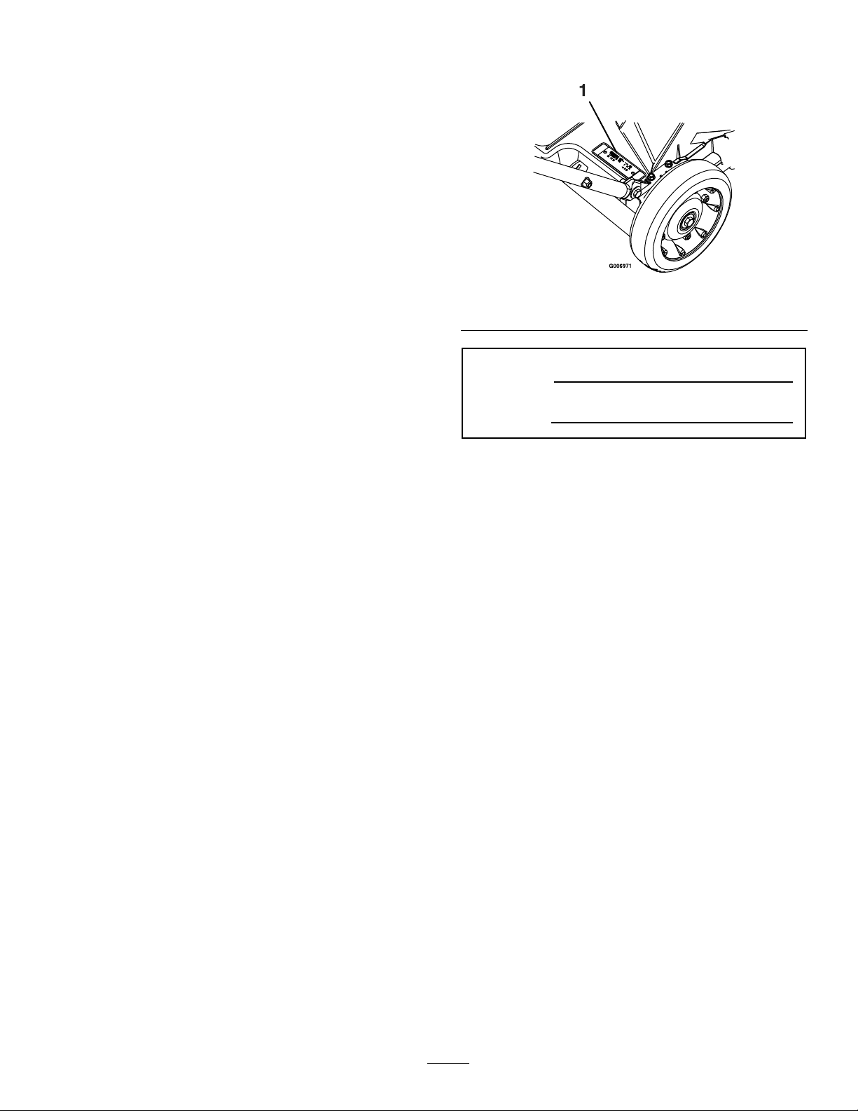
Figure1
1.Modelandserialnumberlocation
Byfollowingtheoperating,maintenance,andsafety
instructions,youwillprolongthelifeofyourmower,
maintainitsmaximumefciency,andpromotesafe
operation.
Ifadditionalinformationisneeded,orshouldyou
requiretrainedmechanicservice,contactyour
authorizedExmarkequipmentdealerordistributor.
AllExmarkequipmentdealersanddistributorsare
keptinformedofthelatestmethodsofservicing
andareequippedtoprovidepromptandefcient
serviceintheeldorattheirservicestations.They
carryamplestockofservicepartsorcansecurethem
promptlyforyoufromthefactory.
AllExmarkpartsarethoroughlytestedandinspected
beforeleavingthefactory,however,attentionis
requiredonyourpartifyouaretoobtainthefullest
measureofsatisfactionandperformance.
Wheneveryouneedservice,genuineExmarkparts,
oradditionalinformation,contactanAuthorized
ServiceDealerorExmarkCustomerServiceandhave
themodelandserialnumbersofyourproductready.
ModelNo.
SerialNo.
Figure1identiesthelocationofthemodelandserial
numbersontheproduct.Writethenumbersinthe
spaceprovided.
3
Page 4

Contents
Introduction...........................................................3
Safety.....................................................................5
SafetyAlertSymbol.........................................5
SafeOperatingPractices..................................5
SafetyandInstructionalDecals.......................9
Specications.......................................................12
ModelNumbers............................................12
Systems.........................................................12
Dimensions...................................................12
ProductOverview................................................13
Operation.............................................................14
Controls........................................................14
Pre-Start........................................................15
OperatingInstructions..................................16
Maintenance.........................................................23
RecommendedMaintenanceSchedule(s)...........23
PeriodicMaintenance.......................................24
CheckEngineOilLevel.................................24
CheckingtheBladeBrakeClutch(For
UnitswithaBladeBrakeClutch
Only).........................................................24
ChecktheMowerBlade.................................24
CheckforLooseHardware............................26
ServiceAirFilter(KawasakiUnits).................26
ServiceAirFilter(HondaUnits).....................27
ChangeEngineOil........................................28
ChangingtheOilFilter(KawasakiUnits
Only):........................................................28
ServicingtheWheels.....................................29
CheckConditionOfBelt(Self-Propelled
UnitsOnly)...............................................29
LubricatethePivotArms...............................29
LubricatetheGearCase(Self-Propelled
UnitsOnly)...............................................30
CheckSparkPlugs.........................................30
Adjustments.....................................................31
AdjustingtheSelf-Propel
Drive(Self-PropelledUnitsOnly)...............31
AdjustingtheBladeBrakeCable....................31
Cleaning...........................................................32
CleanGrassBuild-UpUnderDeck................32
CleaningtheDischargeTunneland
Plug...........................................................32
CleaningUndertheBelt
Cover(Self-PropelledModelsOnly)...........33
CleaningtheBladeBrakeClutch
Shield........................................................33
EmptyingtheFuelTankandCleaning
theFuelFilter(KawasakiUnits
Only).........................................................34
WasteDisposal..............................................34
Storage.................................................................35
PreparingtheFuelSystem..............................35
PreparingtheEngine.....................................35
GeneralStorageInformation.........................35
RemovingtheLawnMowerfrom
Storage......................................................35
Troubleshooting...................................................36
4
Page 5
Safety
Safety
SafetyAlertSymbol
ThislawnmowermeetsorexceedstheCPSCblade
safetyrequirementsforwalk-behindrotarymowers
andtheB71.4specicationsoftheAmericanNational
StandardsInstituteineffectatthetimeofproduction
Exmarkdesignedandtestedthislawnmowertooffer
reasonablysafeservice;however,failuretocomply
withthefollowinginstructionsmayresultinpersonal
injury.
ThisSafetyAlertSymbol(Figure2)isusedbothin
thismanualandonthemachinetoidentifyimportant
safetymessageswhichmustbefollowedtoavoid
accidents
Thissymbolmeans:ATTENTION!BECOME
ALERT!YOURSAFETYISINVOLVED!
SafeOperatingPractices
Training
•ReadtheOperator’sManualandothertraining
material.Iftheoperator(s)ormechanic(s)can
notreadEnglishitistheowner’sresponsibilityto
explainthismaterialtothem.
•Becomefamiliarwiththesafeoperationofthe
equipment,operatorcontrols,andsafetysigns.
•Alloperatorsandmechanicsshouldbetrained.
Theownerisresponsiblefortrainingtheusers.
•Neverletchildrenoruntrainedpeopleoperate
orservicetheequipment.Localregulationsmay
restricttheageoftheoperator.
•Theowner/usercanpreventandisresponsible
foraccidentsorinjuriesoccurringtohimselfor
herself,otherpeopleorproperty.
Preparation
Figure2
1.Safetyalertsymbol
Thesafetyalertsymbolappearsaboveinformation
whichalertsyoutounsafeactionsorsituations
andwillbefollowedbythewordDANGER,
WARNING,orCAUTION.
DANGER:Whitelettering/Redbackground.
Indicatesanimminentlyhazardoussituationwhich,if
notavoided,Willresultindeathorseriousinjury.
WARNING:Blacklettering/Orangebackground.
Indicatesapotentiallyhazardoussituationwhich,if
notavoided,Couldresultindeathorseriousinjury.
CAUTION:Blacklettering/Y ellowbackground.
Indicatesapotentiallyhazardoussituationwhich,if
notavoided,Mayresultinminorormoderateinjury.
Thismanualusestwootherwordstohighlight
information.Importantcallsattentiontospecial
mechanicalinformationandNoteemphasizes
generalinformationworthyofspecialattention.
•Evaluatetheterraintodeterminewhataccessories
andattachmentsareneededtoproperlyand
safelyperformthejob.Onlyuseaccessoriesand
attachmentsapprovedbyExmark.
•Wearappropriateclothingincludingsafetyglasses,
substantialfootwear,longtrousers,andhearing
protection.DoNotoperatewhenbarefootor
whenwearingopensandals.Longhair,loose
clothingorjewelrymaygettangledinmoving
parts.
CAUTION
Thismachineproducessoundlevelsin
excessof85dBAattheoperator’searand
cancausehearinglossthroughextended
periodsofexposure.
Wearhearingprotectionwhenoperatingthis
machine.
•Inspecttheareawheretheequipmentistobe
usedandremoveallrocks,toys,sticks,wires,
bones,andotherforeignobjectswhichcanbe
thrownbythemachineandmaycausepersonal
injurytotheoperatororbystanders.
5
Page 6
Safety
DANGER
Incertainconditionsgasolineisextremely
ammableandvaporsareexplosive.
Areorexplosionfromgasolinecanburn
you,others,andcausepropertydamage.
•Fillthefueltankoutdoorsinanopen
area,whentheengineiscold.Wipeup
anygasolinethatspills.
•Neverrellthefueltankordrainthe
machineindoorsorinsideanenclosed
trailer.
•DoNotllthefueltankcompletely
full.Addgasolinetothefueltankuntil
thelevelis1/4to1/2inch(6–13mm)
belowthebottomofthellerneck.This
emptyspaceinthetankallowsgasoline
toexpand.
•Neversmokewhenhandlinggasoline,
andstayawayfromanopenameor
wheregasolinefumesmaybeignitedby
spark.
•Storegasolineinanapprovedcontainer
andkeepitoutofthereachofchildren.
•Addfuelbeforestartingtheengine.
Neverremovethecapofthefueltankor
addfuelwhenengineisrunningorwhen
theengineishot.
•Iffuelisspilled,DoNotattempttostart
theengine.Moveawayfromtheareaof
thespillandavoidcreatinganysourceof
ignitionuntilfuelvaporshavedissipated.
•DoNotoperatewithoutentireexhaust
systeminplaceandinproperworking
condition.
DANGER
Incertainconditionsduringfueling,static
electricitycanbereleasedcausingaspark
whichcanignitegasolinevapors.Areor
explosionfromgasolinecanburnyouand
othersandcausepropertydamage.
•Alwaysplacegasolinecontainersonthe
groundawayfromyourvehiclebefore
lling.
•DoNotllgasolinecontainersinsidea
vehicleoronatruckortrailerbedbecause
interiorcarpetsorplastictruckbedliners
mayinsulatethecontainerandslowthe
lossofanystaticcharge.
•Whenpractical,removegas-powered
equipmentfromthetruckortrailerand
refueltheequipmentwithitswheelson
theground.
•Ifthisisnotpossible,thenrefuelsuch
equipmentonatruckortrailerfroma
portablecontainer,ratherthanfroma
gasolinedispensernozzle.
•Ifagasolinedispensernozzlemustbe
used,keepthenozzleincontactwiththe
rimofthefueltankorcontaineropening
atalltimesuntilfuelingiscomplete.
WARNING
Gasolineisharmfulorfatalifswallowed.
Long-termexposuretovaporshascaused
cancerinlaboratoryanimals.Failuretouse
cautionmaycauseseriousinjuryorillness.
•Avoidprolongedbreathingofvapors.
•Keepfaceawayfromnozzleandgas
tank/containeropening.
•Keepawayfromeyesandskin.
•Neversiphonbymouth.
•Checkthattheoperator’spresencecontrols,
safetyswitches,andshieldsareattachedand
functioningproperly .DoNotoperateunlessthey
arefunctioningproperly.
6
Page 7

Safety
Operation
WARNING
Operatingengineparts,especiallythe
mufer,becomeextremelyhot.Severeburns
canoccuroncontactanddebris,suchas
leaves,grass,brush,etc.cancatchre.
•Allowengineparts,especiallythemufer,
tocoolbeforetouching.
•Removeaccumulateddebrisfrommufer
andenginearea.
•Installandmaintaininworkingordera
sparkarresterbeforeusingequipment
onforest-covered,grass-covered,or
brush-coveredunimprovedland.
WARNING
Engineexhaustcontainscarbonmonoxide,
whichisanodorlessdeadlypoisonthatcan
killyou.
DoNotrunengineindoorsorinasmall
connedareawheredangerouscarbon
monoxidefumescancollect.
•Operateonlyindaylightorgoodarticiallight,
keepingawayfromholesandhiddenhazards.
•Starttheenginecarefullyaccordingtoinstructions
withfeetwellawayfromtheblades.
•Neverraisedeckwithbladesrunning.
•Neveroperatethemowerwithdamagedguards,
shields,orcovers.Alwayshavesafetyshields,
guards,switchesandotherdevicesinplaceandin
properworkingcondition.
•Nevermowwiththedischargedeectorraised,
removedoralteredunlessthereisagrass
collectionsystemormulchkitinplaceand
workingproperly .
•Grasscatchercomponentsaresubjecttowear,
damageanddeterioration,whichcouldexpose
movingpartsorallowobjectstobethrown.
Frequentlycheckthecomponentsandreplace
themwiththemanufacturer’srecommendedparts
whennecessary.
•DoNotchangetheenginegovernorsettingor
overspeedtheengine.
•Neverattempttomakewheelheightadjustments
whiletheengineisrunning.
•Stopengine,waitforallmovingpartstostop,
removethesparkplugwire(s)and/orremovekey .
–Beforechecking,cleaningorworkingonthe
mower.
–Afterstrikingaforeignobjectorabnormal
vibrationoccurs(inspectthemowerfor
damageandmakerepairsbeforerestarting
andoperatingthemower).
–Beforeclearingblockages.
–Wheneveryouleavethemower.
•Stopengine,waitforallmovingpartstostop:
–Beforerefueling.
–Beforedumpingthegrasscatcher.
–Beforemakingheightadjustments.
WARNING
Hands,feet,hair,clothing,oraccessoriescan
becomeentangledinrotatingparts.Contact
withtherotatingpartscancausetraumatic
amputationorseverelacerations.
•DoNotoperatethemachinewithout
guards,shields,andsafetydevicesin
placeandworkingproperly.
•Keephands,feet,hair,jewelry,orclothing
awayfromrotatingparts.
•Keepclearofthedischargeopeningatalltimes.
•Toextendthelifetheenginebrake,placethe
throttlecontrolinthe“slow”position;thenstop
theengine.
•Thismowerwasdesignedforoneoperator
only.Keepallothersawayfrommowerduring
operation.
•DONOToperatethemowerwhenpeople,
especiallychildren,orpetsareinthearea.
•Bealert,slowdownandusecautionwhenmaking
turns.Lookbehindandtothesidebefore
changingdirections.
•Stoptheblades,slowdown,andusecautionwhen
crossingsurfacesotherthangrassandwhen
transportingthemowertoandfromtheareato
bemowed.
7
Page 8
Safety
•Beawareofthemowerdischargepathanddirect
dischargeawayfromothers.
•DoNotoperatethemowerundertheinuence
ofalcoholordrugs.
•Useextremecarewhenloadingorunloadingthe
machineintoatrailerortruck.
•Usecarewhenapproachingblindcorners,shrubs,
trees,orotherobjectsthatmayobscurevision.
SlopeOperation
UseExtremecautionwhenmowingand/orturning
onslopesaslossoftractionand/ortip-overcould
occur.Theoperatorisresponsibleforsafeoperation
onslopes.
DANGER
Operatingonwetgrassorsteepslopescan
causeslidingandlossofcontrol.Lossof
controland/orlossofoperator’sfooting
couldresultinafallwithanarmorleg
gettingunderthemowerorenginedeck
whichmayresultinseriousinjury,deathor
drowning.
•Mowacrossslopes,neverupanddown.
•DoNotmowslopeswhengrassiswet.
•DoNotmowneardrop-offsornearwater.
•DoNotmowexcessivelysteepslopes.
•Reducespeedanduseextremecaution
onslopes.
•Avoidsuddenturnsorrapidspeed
changes.
•Whenfeasible,avoidoperatingtheequipmentin
wetgrass.
•Progressivelygreatercareisneededastheslope
increases.
•Removeormarkobstaclessuchasrocks,tree
limbs,etc.fromthemowingarea.Tallgrasscan
hideobstacles.
•Watchforditches,holes,rocks,dipsandrisesthat
changetheoperatingangle,asroughterraincould
overturnthemachine.
•Useextremecarewithgrasscatchersor
attachments.Thesecanchangethestabilityofthe
machineandcauselossofcontrol.
MaintenanceandStorage
•Stoptheengineandremovethesparkplugwire(s)
and/orremovekey.Waitforallmovementto
stopbeforeadjusting,cleaningorrepairing.
•Keepengineandengineareafreefrom
accumulationofgrass,leaves,excessivegrease
oroil,andotherdebriswhichcanaccumulate
intheseareas.Thesematerialscanbecome
combustibleandmayresultinare.
•LetenginecoolbeforestoringandDoNotstore
nearameoranyenclosedareawhereopenpilot
lightsorheatappliancesarepresent.
•Shutofffuelwhilestoringortransporting.Do
Notstorefuelnearamesordrainindoors.
•Parkmachineonlevelground.Neverallow
untrainedpersonneltoservicemachine.
•Removesparkplugwirebeforemakingany
repairs.
•Usecarewhencheckingblades.Wraptheblade(s)
orweargloves,andusecautionwhenservicing
them.Onlyreplaceblades.Neverstraightenor
weldthem.
•Keephandsandfeetawayfrommovingparts.
Ifpossible,DoNotmakeadjustmentswiththe
enginerunning.
•Keepallguards,shieldsandallsafetydevicesin
placeandinsafeworkingcondition.
•Checkallboltsfrequentlytomaintainproper
tightness.
•Frequentlycheckforwornordeteriorating
componentsthatcouldcreateahazard.
•Allreplacementpartsmustbethesameas
orequivalenttothepartssuppliedasoriginal
equipment.
8
Page 9
SafetyandInstructionalDecals
Safety
•Keepallsafetysignslegible.Removeallgrease,
dirtanddebrisfromsafetysignsandinstructional
labels.
•Replaceallworn,damaged,ormissingsafety
signs.
•Whenreplacementcomponentsareinstalled,be
surethatcurrentsafetysignsareafxedtothe
replacedcomponents.
•Ifanattachmentoraccessoryhasbeeninstalled,
makesurecurrentsafetysignsarevisible.
•Newsafetysignsmaybeobtainedfrom
yourauthorizedExmarkequipmentdealeror
distributororfromExmarkMfg.Co.Inc.
•Safetysignsmaybeafxedbypeelingoffthe
backingtoexposetheadhesivesurface.Apply
onlytoaclean,drysurface.Smoothtoremove
anyairbubbles.
•Familiarizeyourselfwiththefollowingsafetysigns
andinstructionlabels.Theyarecriticaltothesafe
operationofyourExmarkcommercialmower.
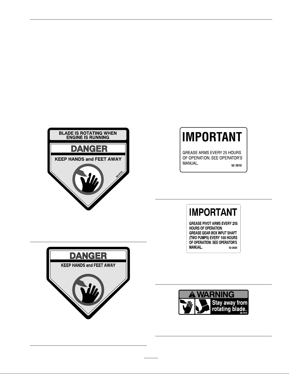
52-2610
ForPushUnits
(MPKA21andMPKA21CA)
39-5770
ForUnitswithoutaBladeBrakeClutch
(MPKA21,MPKA21CA,MSKA21,MSKA21CA,
andMSHN21)
43-8480
ForUnitswithaBladeBrakeClutch
(MSKA21B,MSHN21B,andMSKA21BCA)
52-2620
ForSelf-PropelledUnits
(MSKA21,MSKA21CA,MSKA21B,MSKA21BCA,
MSHN21,andMSHN21B)
68-7410
CommontoAllUnits
9
Page 10
Safety
ForSelf-PropelledUnits
(MSKA21,MSKA21CA,MSKA21B,MSKA21BCA,
MSHN21,andMSHN21B)
1.Transmissionspeeds2.Neutral
74-1970
77-0500
CommontoAllUnits
93-7398
CommontoAllUnits
103-6328
ForMSKA21BandMSHN21BUnitsOnly
1.Choke4.Slow
2.Fast5.Engine—stop
3.Continuousvariable
setting
104-1329
CommontoAllUnits
103-6327
ForMPKA21,MSKA21,andMSHN21UnitsOnly
1.Choke3.Continuousvariable
2.Fast
setting
4.Slow
104-8585
CommontoAllUnits
10
Page 11
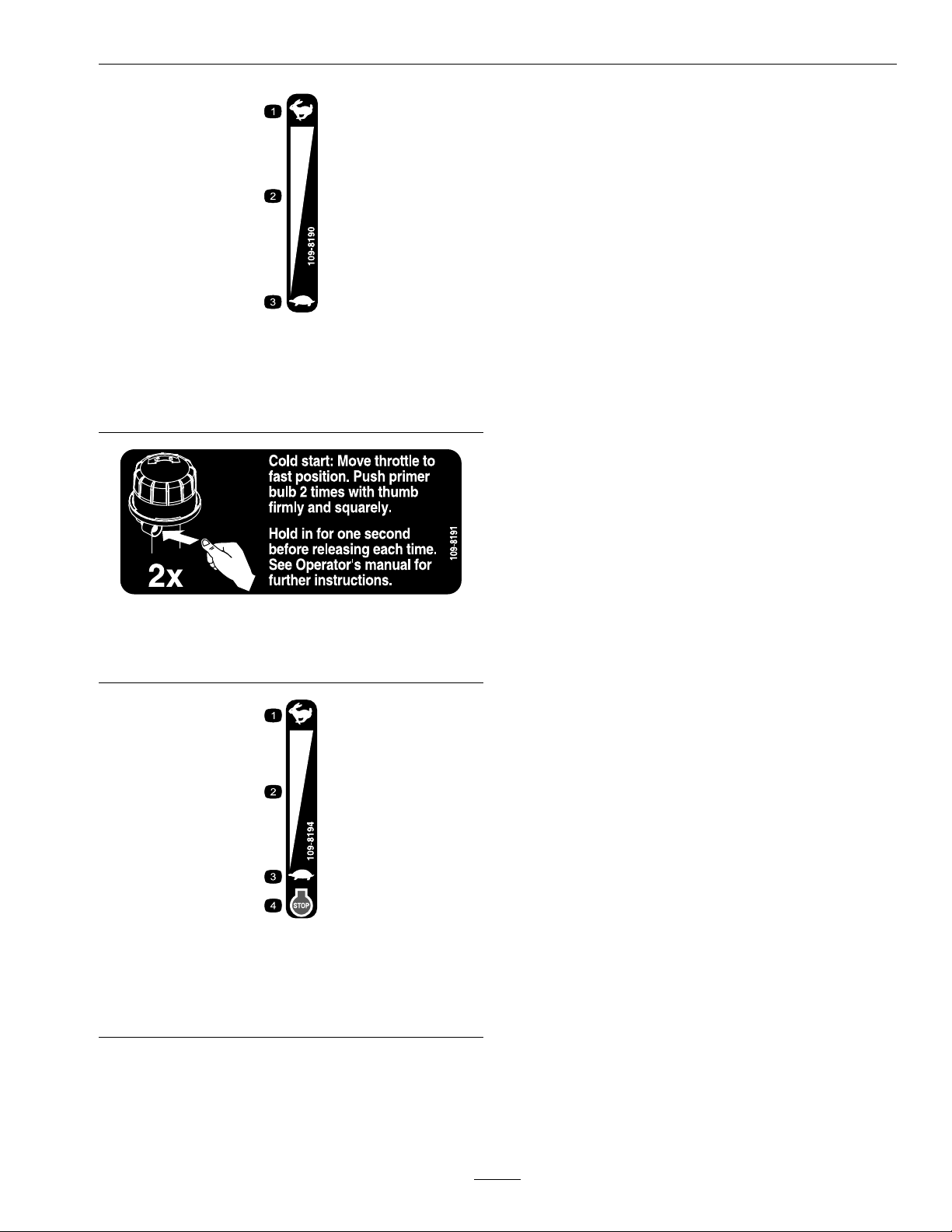
109-8190
OnMPKA21CAandMSKA21CAUnitsOnly
1.Fast
2.Continuousvariable
setting
3.Slow
Safety
1.Fast
2.Continuousvariable
setting
109-8191
OnMPKA21CA,MSKA21CA,
andMSKA21BCAUnitsOnly
109-8194
OnMSKA21BCAUnitsOnly
3.Slow
4.Engine—stop
11
Page 12

Specications
Specications
ModelNumbers
SerialNos:790,000andHigher
MPKA21;MPKA21CA;MSKA21;MSKA21CA;MSKA21B;MSKA21BCA;MSHN21;MSHN21B
Systems
Engine
•EngineSpecications:SeeyourEngineOwner’s
Manual
•RPM:3300(NoLoad)
FuelSystem
•Capacity:
MPKA21,MSKA21,andMSKA21BUnits:
4.0qt(3.8L)
MPKA21CA,MSKA21CA,andMSKA21BCA
Units:2.1qt(2.0L)
HondaUnits:2.1qt(2.0L)
•TypeofFuel:Regularunleadedgasoline,87
octaneorhigher.
•FuelFilter:Non-replaceable,intank
•FuelShut-OffValve:MPKA21,MSKA21,and
MSKA21BandHondaUnits:In-line1/4turn
increments.
MPKA21CA,MSKA21CA,andMSKA21BCA
UnitsDoNothaveashut-offvalve.
CuttingDeck
•CuttingWidth:21inches(53.3cm)
•BladeBrake:Whenthebladeengagementcontrol
ismovedtothedisengagedpositionafriction
brakepadstopstherotationoftheblades.
•BladeSize:(1ea.):20.88inches(53.0cm)
•Deck:21inchesrigid.Deckdesignallowsfor
bagging,mulchingorsidedischarge.
•CuttingHeightAdjustment:
Adjustsfrom3/4inches(1.9cm)to31/4inches
(8.3cm)in1/2inch(1.3cm)increments.
•MulchingKit:Standard
•SideDischargeKit:Optional
Dimensions
CurbWeight:
122lb(55kg)Weightsmayvaryslightlydepending
onengineoption.
OverallWidth:
SafetyInterlockSystem
ForunitswithoutaBladeBrakeClutch:Operator
musthavethebladecontrolbaildepressedtostart
theengine.Releasingthebladecontrolbailwillcause
theenginetostop.
Transmission(SelfPropelledUnits)
3speedsforward
SpeedRange:
•1st–2.0mph(3.2km/hr)
•2nd–2.9mph(4.6km/hr)
•3rd–4.1mph(6.6km/hr)
22.25inches(56.5cm)
12
Page 13

ProductOverview
OverallLengthandHeightat
21/4inchCuttingHeight:
HandleSettingLengthHeight
High60.50inches
(153.7cm)
Medium
Low
64.25inches
(163.2cm)
67.00inches
(170.2cm)
OverallLengthandHeightat
AlternateHandleMountingPosition:
HandleSettingLengthHeight
High62.63inches
(159.1cm)
Medium
Low
64.38inches
(163.5cm)
66.25inches
(168.3cm)
42.75inches
(108.6cm)
40.38inches
(102.6cm)
37.88inches
(96.2cm)
37.50inches
(95.3cm)
35.50inches
(90.2cm)
33.63inches
(85.4cm)
ProductOverview
Figure3
1.Sparkplug
2.Oilll/dipstick9.Throttle/Chokecontrol
3.Dischargedoorhandle10.Fueltank
4.Grassbag11.Oillter
5.BladeControlLever
(BladeBrakeUnitsOnly)
6.BladeControlBail13.Cuttingheightlever
7.Handle
8.DriveBail
(Self-PropelledUnits
Only)
12.Airlter
13
Page 14

Operation
Operation
Note:Determinetheleftandrightsidesofthe
machinefromthenormaloperatingposition.
Controls
BladeControlBail
LocatedontheupperhandleasshowninFigure4.
Whenthebladecontrolbailisdepressed,thesystem
sensesthattheoperatorisinthenormaloperator’s
position.
•ForUnitswithaBladeBrakeClutch:When
thebladecontrolbailisreleased,thesystem
sensesthattheoperatorhasmovedfromthe
normaloperatingpositionandwillstoptheblade.
•ForUnitswithoutaBladeBrakeClutch:
Whenthebladecontrolbailisreleased,thesystem
sensesthattheoperatorhasmovedfromthe
normaloperatingpositionandwillkilltheengine.
controllever.Whenthisbailisreleasedtheunitwill
stopmoving.
Throttle-ChokeControl
Thethrottle-chokecontrolislocatedontheleftside
ofthehandlesasshowninFigure4.
Theleverisusedtocontrolenginespeed.Moving
thelevertothefullforward(Choke)positionwill
placetheleverinthechokeposition.Thechokeaids
instartingacoldengine.Movingthethrottlecontrol
forwardwillincreaseenginespeedandmovingitto
therearwilldecreaseenginespeed.
ForunitswithaBladeBrakeControl:The
throttle-chokecontrolalsoincludesanenginekill
position.Movingtheleverintothefullrearward
(Off)positionwillkilltheengine.
Note:MPKA21CA,MSKA21CA,and
MSKA21BCAUnitsDoNothaveachoke.
BladeControlLever(BladeBrake
ClutchUnitsOnly):
Figure4
1.Throttle-ChokeControl
2.BladeControlLever
(BladeBrakeUnitsOnly)
3.BladeControlBail
Self-PropelDriveBail(For
Self-PropelledUnitsOnly)
4.Handle
5.DriveBail
(Self-PropelledUnits
Only)
Thebladecontrolleverislocatedontherightsideof
thehandlenexttotheBladeControlBailasshown
inFigure4.
Movingthebladecontrolleverintothefullforward
positionwhiledepressingthebladecontrolbail
engagestheblade.Releasingthebladecontrolbail
automaticallydisengagestheblades.
GroundSpeed(Shifter)Control
(Self-PropelledUnitsOnly):
Thegroundspeedcontrolislocatedattherearofthe
beltcoverasshowninFigure5.
Thegroundspeedcontrolhasthreesettingswhich
controlthegroundspeedofthemower:1isslow,2
ismedium,and3isfast.
LocatedontheupperhandleasshowninFigure4.
Whentheself-propeldrivebailissqueezed,theunit
willmoveforwardatthespeedsetonthespeed
14
Page 15

Figure5
1.Groundspeedcontrol
FuelShut-OffValve
ForMPKA21,MSKA21,andMSKA21BUnits:
Thefuelshutoffvalveisinstalledonthefuelline
midwaybetweenthefueltankandtheengineas
showninFigure6.
Operation
Figure7
MSHN21andMSHN21BUnits
1.Fuelvalve
ForMPKA21CA,MSKA21CA,andMSKA21BCA
Units:Donothaveafuelshutoffvalve.
Figure6
MPKA21,MSKA21,andMSKA21BUnits
1.Fuelline
2.Fuelvalve
3.Elbowtting
ForMSHN21andMSHN21BUnits:Thefuel
shutoffvalveislocatedontheengineasshownin
Figure7.
Thefuelshutoffvalveshutsofftheowoffuel
whenthemachinewillnotbeusedforafewdays,
whenparkinginsideabuilding,andduringtransport
toandfromthejob.Rotatethevalve1/4turn
clockwisetoshutofffuel.Rotatethevalve1/4turn
counterclockwisetoturnonfuel.
Pre-Start
Fillfueltank.Forbestresultsuseonlyclean,fresh
regulargradeunleadedgasolinewithanoctanerating
of87orhigher.Toensurefreshness,purchaseonly
thequantityofgasolinethatyouexpecttousein
30days.Usingunleadedgasolineresultsinfewer
combustiondepositsandlongerenginelife.See
EngineOwner’sManual.
DoNotaddoiltogasoline.
DoNotusemethanol,gasolinecontainingmethanol,
gasoholcontainingmorethe10%ethanol,premium
gasolineorwhitegas.Usingthesefuelscandamage
theengine’sfuelsystem.
DoNotusegasolinethathasbeenstoredsincethe
lastmowingseasonorlonger.
DoNotoverllfueltank.Neverllthefueltankso
thatthefuellevelrisesabovealevelthatis1/2inch
belowthebottomofthellernecktoallowforfuel
expansionandpreventfuelspillage.
15
Page 16

Operation
Makesureyouunderstandthecontrols,their
locations,theirfunctions,andtheirsafety
requirements.
RefertotheMaintenancesectionandperformallthe
necessaryinspectionandmaintenancesteps.
OperatingInstructions
HandleAdjustment
Thehandlemaybeadjustedtodifferentheightsfor
comfortableoperation.Standbehindthehandleto
determinetheheight.toadjustthehandleheight,
positionthecapscrewsandthelocknutsthatsecure
thehandlelatchestothehandleintotheother
mountingholesinthelatches.
SeeFigure8Aforthehighestpossiblehandleheights.
SeeFigure8Bforthelowestpossiblehandleheights.
1.Installthehardwareinthelowerholesinthe
handleandlatchesasshowninFigure8.
2.Installhardwareinoneofthethreeadjustment
holesintheupperendsofeachofthehandle
latchestoobtainthedesiredhandleheightwithin
theselectedrange.
3.Slidethebagsupportrodthroughintotheupper,
middle,orlowermountingholesinthehandle
andsecureeachendwithacaplocknut.Thebag
supportrodmountingholelocationcorresponds
withthemountingholelocationforthehandle
latchesasshowninthetable.
BagSupportRod
MountingHoleLocation
LowerLower
MiddleMiddle
UpperUpper
HandleLatchMounting
HoleLocation
OpentheFuelShut-OffValve
1.Handlelatch
2.Adjustmentholesin
upperendofhandle
latch
3.Handle
Rotatethevalve1/4turncounterclockwisetoturn
thefuelon.
StartingtheEngine
1.Connectthewiretothesparkplug.
ForMSHN21andMSHN21BUnits:see
Figure9.
ForMPKA21,MSKA21,MSKA21B,
MPKA21CA,MSKA21CA,andMSKA21BCA
Units:seeFigure10.
Figure8
4.Springdiscwasher
5.5/16-18x13/8inchhex
capscrew
6.5/16-18x11/4inchhex
capscrew
16
Page 17

Figure9
AllHondaUnits
Operation
ForMSHN21andMSHN21BUnits:see
Figure7.
MPKA21CA,MSKA21CA,andMSKA21BCA
Units:DoNothaveafuelvalve.
3.ForMSHN21MSHN21B,MPKA21,MSKA21,
andMSKA21BUnits:Movethethrottle-choke
controltotheChokeposition.
Note:DoNotusethechokewhentheengineis
warmsup.
ForMPKA21CA,MSKA21CA,and
MSKA21BCAUnits:Movethethrottlecontrol
totheFastposition.Presstheprimerbulbtwo
times(seeFigure11).
1.Oilll/dipstick
2.Recoilstarterhandle
3.Fueltankcap
AllKawasakiUnits
1.Mufer5.Oillter
2.Oilll/dipstick
3.Fueltankcap
4.Recoilstarterhandle
4.Aircleaner
5.Sparkplug
Figure10
6.Aircleaner
7.Sparkplug
2.Openthefuelvalve.
ForMPKA21,MSKA21,andMSKA21BUnits:
seeFigure6.
Figure11
4.ForunitswithoutaBladeBrakeClutch:Hold
thebladecontrolbailtothehandle.
5.Pullthestarterhandlelightlyuntilyoufeel
resistance,thenpullitsharply.Allowtheropeto
returnslowly.
6.Whentheenginestarts,movethethrottlecontrol
totheFastposition,andsetthegroundspeed
controlasdesired.
Note:Iftheenginefailstostartafterthreepulls,
repeatsteps3through6).
StoppingtheEngine
1.Bringtheunittoafullstop.
•ForunitswithoutaBladeBrakeClutch:
Releasethebladecontrolbail.Boththe
engineandthebladeshouldstopwithinthree
seconds.
•ForunitswithaBladeBrakeClutch:
Releasethebladecontrolbail.Theblade
shouldstopwithinthreeseconds.Movethe
throttletothe(Off)positiontokilltheengine.
17
Page 18

Operation
Note:Ifthebladedoesnotstopwithin3
secondsafterreleasingthebladecontrolbail,
contactanAuthorizedServiceDealer.
2.Closethefuelshut-offvalve,ifequippedwith,
whenthemachinewillnotbeinuseforafew
days,whentransporting,orwhentheunitis
parkedinsideabuilding.
UsingtheSelf-PropelDrive
(Self-PropelledUnitsOnly)
Thelawnmowerhasthreegroundspeeds:1isslow ,
2ismedium,and3isfast.
1.Starttheengine.
2.Usingthegroundspeedcontrol,selectthedesired
groundspeed.
3.Squeezethedrivebailagainstthehandle(see
Figure4).
Note:DoNotshiftspeedswhilesqueezingthe
groundspeedcontrolagainstthehandle.This
candamagethetransmission.Releasetheground
speedcontrolbeforechangingspeeds.
Note:Thebladecontrolleverwillreleaserapidly
whenthebladecontrolbailisreleased.Toavoid
minorinjury,keephandsclearofthebladecontrol
leverwhenthebladecontrolbailisreleased.
UsingtheDischargeTunnel
1.Stoptheengineandwaitforallmovingpartsto
stop.
2.Inserttheplug.(RefertoInstallingthe
DischargePlugsection).
3.Toremovetheplug,movethedischargedoor
handlerearwardandliftupthespringcliponthe
bottomoftheplug.Whentheplugisunlocked,
pullitoutofthedischargetunnel.
Note:Whengrassisthickandlush,clippings
maycollectonandaroundthedischargetunnel
plug.Thismaymakeremovingtheplugdifcult.
Cleantheplugthoroughlyaftereachuse.
CheckingtheBladeBrakeClutch
(BladeBrakeClutchUnitsOnly)
Note:Youcanvarythegroundspeedby
increasingordecreasingthedistancebetweenthe
groundspeedcontrolandthehandle.Lowerthe
controlbartodecreasethegroundspeedwhen
youaremakingaturnorifthelawnmoweris
movingtoofastforyou.Ifyoulowerthecontrol
bartoofarthelawnmowerstopsself-propelling.
Squeezethegroundspeedcontrolclosertothe
handletoincreasethegroundspeed.When
youholdthegroundspeedcontroltightagainst
thehandle,thelawnmowerself-propelsatthe
maximumgroundspeed.Movethegroundspeed
controltotheNeutralpositionwhenyouusethe
lawnmowerfortrimmingorwheneveryouleave
thelawnmower.
OperatingtheBladeControlLever
(BladeBrakeClutchUnitsOnly)
1.Starttheengine.
2.Squeezethebladecontrolbailagainstthehandle
(Figure4).
ChecktheBladeBrakeClutch(BBC)systembefore
eachusetoensurethatitisoperatingproperly.
NormalTest:
1.Stoptheengineandwaitforallmovingpartsto
stop.
2.Movethelawnmowerontoapavedsurfacein
anon-windyarea.
3.Setallfourwheelsintothe21/2inches(6.4cm)
cuttingheight(seeFigure13).
4.SetthegroundspeedselectortotheN(Neutral)
position.
5.Takeahalfsheetofnewspaperandcrumple
itintoballsmallenoughtogounderthedeck
(about3inchesor7.6cmindiameter)asshown
inFigure12.
3.Movethebladecontrollevertothefullforward
Latchposition.Bladesshouldengage.
4.Releasethebladecontrolbailtodisengagethe
blades.
18
Page 19

Operation
DANGER
Ifthebladebrakeclutchsystemis
inoperative,thebladewillcontinuetorotate
whenyoureleasethebladecontrolbail.
Contactwiththebladecouldoccur,causing
seriousinjury.
•ChecktheBBCoperationbeforeeach
use.
•NeverusetheBBC-equippedlawnmower
withaninoperativesafetysystem.
Figure12
1.Crumplednewspaper2.5inches(12.7cm)
6.Placetheballofnewspaper5inches(12.7cm)in
frontofthelawnmower.
7.Starttheengine.
8.Squeezethebladecontrolbailagainstthehandle.
9.Movethebladecontrollevertothefullforward
Latchposition.Bladesshouldengage.
10.Releasethebladecontrolbail.Youshouldheara
“bang.”Thebladeshouldstopinthreeseconds.
11.Immediatelypushthelawnmoweroverthe
newspaperball.
12.Stoptheengineandwaitforallmovingpartsto
stop.
13.W alkaroundthelawnmowertocheckforthe
newspaperball.Iftheballdidnotgounderthe
deck,repeatsteps7through12.
•TakeyourlawnmowertoanAuthorized
ServiceDealerforrepairifthesafety
systemfailstooperateproperly.
TestUsingtheGrassBag
1.Installtheemptygrassbagonthedischarge
tunnel.
2.Starttheengine.
3.Squeezethebladecontrolbailagainstthehandle.
4.Movethebladecontrollevertothefullforward
Latchposition.Thebagshouldbegintoinate,
indicatingthatthebladeisengagedandrotating.
5.Releasethebladecontrolbail.Ifthebagdoesnot
immediatelydeate,itindicatesthatthebladeis
stillrotating.Thebladebrakeclutchmechanism
maydeteriorating,and,ifignoredcouldresultin
anunsafeoperatingcondition.Havethelawn
mowerinspectedandservicedbyanAuthorized
ServiceDealer.
14.Pullthelawnmowerawayfromthenewspaper.
Ifthenewspaperballunravelsorisshredded,
thebladehasnotproperlystopped,resulting
inanunsafeoperatingcondition.Contactan
AuthorizedServiceDealer.
AdjustingtheCuttingHeight
Eachwheelisadjustedindividuallywithawheel
heightadjustmentlever.Thecuttingheightsarelisted
inthefollowingtable.
CuttingHeights
3/4inch(19mm)21/4inches(57mm)
11/4inches(32mm)23/4inches(70mm)
13/4inches(44mm)31/4inches(83mm)
19
Page 20

Operation
WARNING
Adjustingthecuttingheightleverscould
bringyourhandsintocontactwithamoving
blade.Amovingbladecancauseserious
injury.
•Stoptheengineandwaitforallmovement
tostopbeforeadjustingthecutting
height.
•DoNotputyourngersunderthe
housingwhenadjustingthecutting
height.
1.Pullthewheelheightadjustmentlevertoward
thewheel(Figure13)andmoveittothedesired
setting.
Figure14
1.BagFrameonretaining
post.
2.Pinengagedincatch.
3.Handlefully
forward—discharge
doorclosed.
3.Slidetheholeinthebagframeontothe
retainingpostonthedischargetunnel.
Figure13
1.Pulltowardswheel3.Notches
2.WheelHeight
AdjustmentLever
2.Releasethewheelheightadjustmentleverandset
itsecurelyinthenotch.
3.Adjustallthewheelstothesamecuttingheight
setting.
UsingtheGrassBag
Occasionally,youmaywishtousethegrassbagfor
baggingextralonggrass,lushgrass,orleaves.
•InstallingtheGrassBag
4.Settherearofthebagframeontothebag
supportrod.
5.Pullthedischargedoorhandleforwarduntil
thepinclearsthecatch,andmovethehandle
rearwarduntilthepinlocksinthebagnotch
(Figure15).
Figure15
1.Pinlockedinbagnotch.
1.Stoptheengineandwaitforallmovingparts
tostop.
2.Ensurethatthedischargedoorhandleisfully
forwardandthatthepinisengagedinthe
catch(Figure14).
Note:Thedischargedoorinthelawnmower
housingisnowopen.
20
Page 21

Operation
•MowingwiththeGrassBag
WARNING
Aworngrassbagcouldallowsmallstones
andothersimilardebristobethrowninthe
operator’sorbystander’sdirection.Thrown
objectscanresultseriouspersonalinjuryor
deathtotheoperatororbystanders.
Checkthegrassbagfrequently.Ifitis
damaged,installanewExmarkreplacement
bag.
Cutthegrassuntilthebagisfull.
Note:DoNotoverllthebag.
•RemovingtheGrassBag
1.Stoptheengineandwaitforallmovingparts
tostop.
2.Raisethedischargedoorhandleandmove
itforwardtoengagethepinwiththecatch
(Figure14).
3.Graspthehandlesatthefrontandtherearof
thebagandliftthebagoffthelawnmower.
4.Graduallytipthebagforwardtoemptythe
clippings.
5.Toinstallthebag,refertotheInstallingthe
GrassBagsection.
DANGER
Ifthedischargedoordoesnotclose
completely,thelawnmowercouldthrow
objects.Thrownobjectscanresultserious
personalinjuryordeathtotheoperatoror
bystanders.
•Neveropenthedoortothedischarge
openingwhentheengineisrunning.
•Ifyoucannotclosethedoorbecausethe
grassclippingsclogthedischargearea,
stoptheengineandgentlymovethe
dischargedoorhandlebackandforth
untilyoucanclosethedoorcompletely .If
youstillcannotclosethedoor,removethe
obstructionwithastick,notyourhand.
DANGER
Ifthedischargedoordoesnotclose
completely,thelawnmowercouldthrow
objects.Thrownobjectscanresultserious
personalinjuryordeathtotheoperatoror
bystanders.
Neveropenthedooronthedischargetunnel
whentheengineisrunning.
OperatingTips
•ReviewtheSafetysectionandreadthismanual
carefullybeforeoperatingthelawnmower.
•Settheenginespeedtothefastestpositionfor
thebestcuttingresults.
•Maintainasharpbladethroughoutthecutting
season.Periodicallyledownnicksontheblade.
Replacethebladewhennecessarywithanoriginal
Exmarkreplacementblade.
•Cleantheairlterfrequently.Mulchingstirsup
moreclippingsanddustwhichclogstheairlter
andreducesengineperformance.
CuttingGrass
•Grassgrowsatdifferentratesatdifferenttimes
oftheyear.Inthesummerheat,itisbestto
cutgrassatthe21/4inch(57mm),23/4inch
(70mm),or31/4inch(83mm)cuttingheight
settings.Cutonlyaboutathirdofthegrassblade
atatime.DoNotcutbelowthe21/4inch(57
mm)settingunlessthegrassissparseoritislate
fallwhengrassgrowthbeginstoslowdown.
•Whencuttinggrassover6inches(15cm)tall,
rstmowatthehighestcuttingheightsettingand
walkslower;thenmowagainatalowersettingfor
thebestlawnappearance.Ifthegrassistoolong
andtheleavesclumpontopofthelawn,thelawn
mowermayplugandcausetheenginetostall.
•Alternatethemowingdirection.Thishelps
dispersetheclippingsoverthelawnforeven
fertilization.
Ifthenishedlawnappearanceisunsatisfactory,
tryoneormoreofthefollowing:
•Sharpentheblade.
•Walkataslowerpacewhilemowing.
•Cutthegrassmorefrequently .
21
Page 22

Operation
•Overlapcuttingswathsinsteadofcuttingafull
swathwitheachpass.
•Setthecuttingheightonthefrontwheelsone
notchlowerthantherearwheels.Forexample,
setthefrontwheelsat21/4inches(57mm)and
therearwheelsatthe23/4inches(70mm).
CuttingLeaves
•Aftercuttingthelawn,ensurethathalfofthe
lawnshowsthroughthecutleafcover.Youmay
needtomakemorethanonepassovertheleaves.
•Forlightleafcoverage,setallthewheelsatthe
samecuttingheightsetting.
•Iftherearemorethan5inches(12.7cm)ofleaves
onthelawn,setthefrontcuttingheight1or2
notcheshigherthantherearcuttingheight.This
makesiteasiertofeedtheleavesunderthelawn
mowerdeck.
•Slowdownyourmowingspeedifthelawnmower
doesnotcuttheleavenelyenough.
•Ifyoumowoveroakleaves,youcanaddlimeto
thegrassinthespringtoreducetheacidityofthe
oakleaves.
22
Page 23

Maintenance
Note:Determinetheleftandrightsidesofthemachinefromthenormaloperatingposition.
Maintenance
WARNING
Ifyouleavethewireonthesparkplug,
someonecouldaccidentallystarttheengine.
Accidentalstartingoftheenginecould
seriouslyinjureyouorotherbystanders.
Disconnectthewirefromthesparkplug
beforeyoudoanymaintenance.Setthewire
asidesothatitdoesnotaccidentallycontact
thesparkplug.
RecommendedMaintenanceSchedule(s)
MaintenanceService
Interval
Aftertherst5hours
Beforeeachuseordaily
MaintenanceProcedure
•Changetheengineoil.
•Checktheengineoillevel.
•Checkthestoppingtimeofthebladebrake.Theblademuststopwithin3secondsof
releasingthebail;ifitdoesnot,contactandAuthorizedServiceDealerforrepair.
•Checkthemowerbladesandtheenginemountingfasteners.
•Checkforloosehardware.
•Cleanthegrassbuild-upfromunderthedeck.
•Cleanthedischargetunnelandplug.
WARNING
Theenginecanbecomeveryhot.Touching
ahotenginecancausesevereburns.
Allowtheenginetocoolcompletelybefore
serviceormakingrepairsaroundtheengine
area.
Every25hours
Every40hours
Every50hours
Every100hours
Every250hours
Every300hours
Yearly
Yearlyorbeforestorage
•Cleanthefoampre-cleaner(KawasakiUnits).
•Cleanthecover,base,foamandpaperelements(HondaUnits).
•Checktheconditionofthebelt(s).
•Changetheengineoil.(Mayneedmoreoftenundersevereconditions.)
•Greasethepivotarms.
•Cleanunderthebeltcover(self-propelledmodelsonly).
•Cleanthebladebrakeclutchshield.
•Checkforleaksinthefuelsystemsand/ordeterioratingfuelhose.
•Changetheoillter(KawasakiUnitsOnly).
•Servicethewheels.
•Greasethegearcase(self-propelledunitsonly).
•Checkthesparkplugs.
•ForBladeBrakeClutchUnits:Adjustthebladebrakecable.
•Cleanthefuellterelement(KawasakiUnitsOnly).
•Replacetheairlterelements(HondaUnits).(Mayneedmoreofteniftheyaredamaged
orexcessivelydirty.)
•Replacethepaperairlter(KawasakiUnits).(Mayneedmoreoftenindustyconditions.
SeetheEnginemanualforadditionalinformation.)
•Lubricatethegearcase(self-propelledunitsonly)
•Emptythefueltankbeforerepairsasdirectedorbeforestorage.
23
Page 24

Maintenance
PeriodicMaintenance
CheckEngineOilLevel
ServiceInterval:Beforeeachuseordaily
1.Stopengineandwaitforallmovingpartstostop.
Makesureunitisonalevelsurface.
2.Checkwithenginecold.
3.Cleanareaarounddipstick.Removedipstickand
wipeoiloff.Reinsertthedipstickandpushitall
thewaydownintothetube.DoNotscrewinto
place.Removethedipstickandreadtheoillevel.
Figure17
KawasakiEngine
1.Dipstick3.Add
2.Full
Figure16
HondaEngine
1.Lowerlimitmark3.Dipstick
2.Upperlimitmark
4.Iftheoillevelislow ,wipeofftheareaaroundthe
oilllcap,removecapandlltothe“FULL”
markonthedipstick.Useoilasspeciedin
EngineOwner’ sManual.DoNotoverll.
Important:DoNotoperatetheenginewiththe
oillevelbelowthe“LOW”(or“ADD”)markon
thedipstick,oroverthe“FULL”mark.
CheckingtheBladeBrake
Clutch(ForUnitswitha
BladeBrakeClutchOnly)
ServiceInterval:Beforeeachuseordaily
RefertoCheckingtheBladeBrakeClutchinthe
OperatingInstructionssection.
ChecktheMowerBlade
ServiceInterval:Beforeeachuseordaily
Alwaysmowwithasharpblade.Asharpbladecuts
cleanlyandwithouttearingorshreddingthegrass
blades.
1.Stoptheengineandwaitforallmovingpartsto
stop.
2.Disconnectthewirefromthesparkplug(Figure9
andFigure10).
3.Drainthegasolinefromthefueltank.
24
Page 25

4.Tipthelawnmowerontoitsrightside(see
Figure18andFigure19).
Figure18
BladeBrakeClutchUnitsOnly
Maintenance
Figure20
1.Sail
2.Flat
3.Wear
4.Slot
1.Accelerator3.Blade
2.Anti-ScalpCup
UnitsWithoutaBladeBrakeClutchOnly
1.Blade3.Accelerator
2.BladeBolt
4.BladeNuts
Figure19
5.Inspectthebladeforsharpnessandwear,
especiallywheretheatandthecurvedparts
meet(seeFigure20A).Becausesandandabrasive
materialcanwearawaythemetalthatconnects
theatandcurvedpartsoftheblade,check
thebladebeforeusingthelawnmower.Ifyou
noticeaslotorwear(Figure20BandFigure20C),
replacetheblade.
Note:Forthebestperformance,installanew
bladebeforethecuttingseasonbegins.During
theyear,ledownanysmallnickstomaintainthe
cuttingedge.
DANGER
Awornordamagedbladecanbreak.A
pieceofthebladecouldbethrownintothe
operator’sorbystander’sarea,resultingin
seriouspersonalinjuryordeath.
•Inspectthebladeperiodicallyforwearor
damage.
•Replaceawornordamagedblade.
Ifitisnecessarytoremovethebladefor
replacementorsharpening,completethe
followingsteps:
6.Removetheblade.Makesuretograsptheendof
thebladeusingaragorathicklypaddedglove.
•ForBladeBrakeClutchUnits:Removethe
bladenuts,anti-scalpcup,accelerator,andthe
blade(Figure18).
•ForUnitswithoutaBladeBrakeClutch:
Removethebladebolt,accelerator,andblade
(Figure19).
7.ForSharpening:Filethetopsideofthebladeto
maintainitsoriginalcuttingangle(Figure21A)
andinnercuttingedgeradius(Figure21B).The
bladewillremainbalancedifyouremovethesame
amountofmaterialfrombothcuttingedges.
25
Page 26

Maintenance
10.Returnthelawnmowertoitsuprightposition.
11.Connectthewiretothesparkplug.
Figure21
1.Cuttingangle2.Cuttingedgeradius
8.Checkthebalanceofthebladebyplacingthe
centerholeofthebladeoveranailorscrewdriver
shankclampedhorizontallyinavise(Figure22).
Ifeitherendofthebladerotatesdownward,le
thatend(notthecuttingedge).Thebladeis
properlybalancedwhenneitherenddrops.
Figure22
1.Blade
2.Vise
9.ForInstallation:Makesuretograsptheendof
thebladeusingaragorathicklypaddedglove.
ForBladeBrakeClutchUnits:Installasharp,
balancedExmarkblade,theaccelerator,the
anti-scalpcup,andthebladenuts.Thesailof
theblademustpointtowardthetopofthelawn
mowerhousingforproperinstallation.Torque
thebladenutsto15-27ft-lb(20-37Nm).
ForUnitswithoutaBladeBrakeClutch:Installa
sharp,balancedExmarkblade,theaccelerator,
andbladebolt.Thesailoftheblademustpoint
towardthetopofthelawnmowerhousingfor
properinstallation.Torquethebladenutsto50
ft-lb(68Nm).
3.Screwdriver
CheckforLooseHardware
ServiceInterval:Beforeeachuseordaily
1.Stopengine,waitforallmovingpartstostop,and
removekey.Engageparkingbrake.
2.Visuallyinspectmachineforanyloosehardware
oranyotherpossibleproblem.Tightenhardware
orcorrecttheproblembeforeoperating.
ServiceAirFilter
(KawasakiUnits)
ServiceInterval:Every25hours—Clean
thefoampre-cleaner
(KawasakiUnits).
Every300hours—
Replacethepaperair
lter(KawasakiUnits).
(Mayneedmoreoftenin
dustyconditions.See
theEnginemanualfor
additionalinformation.)
Note:DoNotoperatetheenginewithouttheair
lterassembly;extremeenginedamagewilloccur.
1.Stopengine,waitforallmovingpartstostop.
2.Disconnectthewirefromthesparkplug
(Figure10).
3.Removethecoverandcleanitthoroughly .
DANGER
Operatingthelawnmowerwithoutthe
acceleratorinplacecancausethebladeto
ex,bend,orbreak.Thrownobjectsfroma
brokenbladecanresultinseriousinjuryor
deathtotheoperatororbystanders.
DoNotoperatethelawnmowerwithoutthe
accelerator.
26
Page 27

Figure23
1.Cover3.Paperairlter
2.Foampre-cleaner
4.Airlterbase
4.Removethepaperairlteranddiscarditas
required.
Maintenance
2.Disconnectthewirefromthesparkplug
(Figure9).
3.Removethetwowingnutsthatsecurethecover
(Figure24).
Note:DoNottrytocleanapaperairlter.
5.Removethefoampre-cleanerandwashitwitha
milddetergentandwater,thenblotitdry.
6.Saturatethepre-cleanerwithcleanengineoil,then
squeezeit(DoNottwist)toremovetheexcessoil.
7.Installthefoampre-cleaner.
8.Installthenewpaperairlter.
9.Installthecover.
ServiceAirFilter
(HondaUnits)
ServiceInterval:Every25hours—Clean
thecover,base,foamand
paperelements(Honda
Units).
Every250hours—Replace
theairlterelements
(HondaUnits).(Mayneed
moreofteniftheyare
damagedorexcessively
dirty.)
Note:DoNotoperatetheenginewithouttheair
cleanerassembly;extremeenginedamagewilloccur.
1.Stoptheengineandwaitforallmovingpartsto
stop.
Figure24
1.Wingnuts4.Foamelement
2.Cover
3.Paperelement
5.Base
4.Removethecover.
Note:Becarefultopreventdirtanddebrisfrom
fallingintothebase.
5.Removethefoamandpaperelementsfromthe
base.
6.Removethefoamelementfromthepaper
element.
7.Inspectthefoamandpaperelements,andreplace
themiftheyaredamagedorexcessivelydirty.
8.Tapthepaperelementonahardsurfaceseveral
timesorusecompressedairnotexceeding30
psi(207kPa)throughthelterfromthewire
screensidetoremoveanyexcessdirt.Ifthepaper
elementisexcessivelydirty,replaceit.
Note:Nevertrytobrushdirtoffthepaper
element;brushingforcesthedirtintothebers.
9.Cleanthefoamelementinwarm,soapywateror
inanonammablesolvent.
10.Rinseanddrythefoamelementthoroughly.
27
Page 28

Maintenance
11.Dipthefoamelementincleanengineoil,then
squeezeouttheexcessoil.
Note:Excessoilinthefoamelementrestricts
theairowthroughtheelementandmayreach
thepaperlterandclogit.
12.Wipedirtfromthebaseandthecoverwitha
moistrag.
Note:Becarefultopreventdirtanddebrisfrom
enteringtheairductleadingtothecarburetor.
13.Installtheaircleanerelementsandensurethat
theyareproperlypositioned.
14.Securelyinstallthecoverwiththetwowingnuts.
ChangeEngineOil
ServiceInterval:Aftertherst5hours
Every50hours(Mayneed
moreoftenundersevere
conditions.)
1.Runtheenginetowarmtheengineoil.
Note:Warmoilowsbetterandcarriesmore
contaminates.
11.Wipeupanyspilledoil.
12.Connectthewiretothesparkplug.
13.Recycletheusedoilaccordingtolocalcodes.
ChangingtheOilFilter
(KawasakiUnitsOnly):
ServiceInterval:Every100hours
1.Runtheenginetowarmtheoil.
2.Stoptheengineandwaitforallmovingpartsto
stop.
3.Disconnectthewirefromthesparkplug.
4.Draintheengineoil.
5.Placearagundertheoilltertocatchanyoilthat
mayleakoutasyouremovethelter.
6.Removetheoillter.
7.Useyourngertocoatthegasketonthenew
lterwithcleanengineoil(seeFigure25).
WARNING
Oilmaybehotafterenginehasbeen
run.Contactwithhotoilcancausesevere
personalinjury.
Avoidcontactingthehotengineoilwhenyou
drainit.
2.Stopengine,waitforallmovingpartstostop.
3.Disconnectthewirefromthesparkplug.
4.Placeasuitabledrainpanunderthedipstick/oil
drain.
5.Cleanaroundthedipstick.
6.Removethedipstickbyrotatingthecap
counterclockwiseandpullingitout.
7.Raisetheleftsideofthelawnmowertodrainthe
oilfromthedipsticklltubeintothedrainpan.
8.Afterdrainingtheoil,returnthelawnmowerto
theoperatingposition.
9.Fillthecrankcasewithfreshoiltotheupperlimit
markonthedipstick.
10.Insertthedipstickintothellerneckandrotate
thecapclockwiseuntilitistight.
Figure25
1.Gasket
8.Installthenewlterandhandtightenit2/3turn
only.
9.FillthecrankcasetotheFulllineonthedipstick
withfreshoil.
10.Connectthewiretothesparkplug.
11.Runtheengineforabout3minutes.
12.Stoptheengine,waitforallmovingpartstostop,
andcheckforoilleakagearoundthelter.
13.Addoiltocompensatefortheoilintheoillter.
14.Recycletheusedoillteraccordingtolocalcodes.
28
Page 29

Maintenance
ServicingtheWheels
ServiceInterval:Every100hours
RemovingtheWheels
1.Stopengine,waitforallmovingpartstostop.
2.Disconnectthewirefromthesparkplug.
3.Removethebolt,thewheelspacer,andthe
locknutmountingthewheeltothepivotarm
(Figure26).
Figure26
1.PlasticCover6.BearingSpacer
2.Locknut
3.Wheelhalf
4.Bolt
5.Bearing
7.Bearing/HubAssembly
8.Lug
9.WheelSpacer
wheelhalvesandtighten.Removethetwolong
screwsorboltsandreplacethemwithtwocap
screwsandtwolocknuts.
7.Installthewheeltothepivotarmwiththecap
screws,aspacer,andalocknut.Ensurethatthe
spacerispositionedbetweenthewheelhuband
thepivotarm.
8.Connectthewiretothesparkplug.
CheckConditionOfBelt
(Self-PropelledUnitsOnly)
ServiceInterval:Every40hours
1.Stopengine,waitforallmovingpartstostop.
2.Removetheboltsthatsecurethebeltcovertothe
lawnmowerhousing.
3.Checkthebeltforcracks,frayededges,burn
marksoranyotherdamage.
4.Replacethedamagedbelt.
LubricatethePivotArms
4.Separatethewheelhalvesfromthetireby
removingfourboltsandfourlocknuts.
Note:Ifyouremovethebearingsfromthe
bearing/hubassembly ,removethembypressing
onthebearingspacer.
AssemblingtheWheels
1.Positionthetireontoonewheelhalf,aligningthe
lugsoneach.
2.Placethebearing/hubassemblyintothecenter
holeofthewheelhalf.Ensurethatthelegsofthe
hubarepositionedovertheangeofthehole.
3.Placetheotherwheelhalfontothebearing/hub
assembly,aligningthewheelandthetirelugsand
themountingholes.
4.Usingtwofullythreadedscrewsorboltsand
non-lockingnuts,looselysecurethewheelhalves
together.Mountthescrewsorboltsinthe
opposingholes.
5.Checkthealignmentofallpartsandtightenthe
screws,alternatingfromsidetosideforauniform
tuntilthewheelhalvesaredrawntogether.
6.Installthetwocapscrewsandtwolocknuts
previouslyremovedintheremainingholesinthe
1.Movetherearwheelcuttingheightleverstothe
centersetting.
2.Wipethegreasettingswithacleanrag
(Figure27).
Figure27
1.Greasetting
3.Installagreasegunontothettingandgently
apply2or3pumpsof#2multi-purposelithium
basegrease.
Note:Excessivegreasepressuremaydamagethe
seals.
29
Page 30

Maintenance
1.Stopengine,waitforallmovingpartstostop,and
removekey.Engageparkingbrake.
2.Lubricatettingswithonetotwopumpsof
NGLIgrade#2multi-purposegungrease.
Refertothefollowingchartforttinglocations
andlubricationschedule.
LubricationChart
Fitting
Locations
1.Pivot
Arms
2.Gear
Case
Initial
Pumps
22
11
Numberof
Places
Service
Interval
50Hours
100Hours
LubricatetheGearCase
(Self-PropelledUnitsOnly)
ServiceInterval:Yearly
CheckSparkPlugs
ServiceInterval:Every100hours
1.Stoptheengineandwaitforallmovingpartsto
stop.
2.Disconnectthewirefromthesparkplug(Figure9
andFigure10).
3.Cleanaroundthesparkplug.
4.Removethesparkplugfromthecylinderhead.
Note:Replaceacracked,fouled,ordirtyspark
plug.DoNotcleantheelectrodesbecausegrit
enteringthecylindercandamagetheengine.
5.Setthegapontheplugto0.030inch(0.76mm)
(Figure29).
1.Stopengine,waitforallmovingpartstostop.
2.Removethegrassbag.
3.Installagreasegunontothettingthroughthe
beltcoveropening
Figure28
1.Greasetting
2.Beltcover
4.Gentlyapplyonetotwopumpsof#2
multi-purposelithium-basegrease.
Figure29
1.Sideelectrode
2.Centerelectrode
insulator
3.Airgap—0.030inch
(0.76mm)
6.Installthesparkplugandthegasketseal.
7.Torquetheplugto17ft-lb(23N-m).
8.Connectthewiretothesparkplug.
5.Installthegrassbag.
30
Page 31

Maintenance
Adjustments
Note:Waitforallmovingpartstostopandremove
sparkplugwirebeforeservicing,cleaning,ormaking
anyadjustmentstotheunit.
AdjustingtheSelf-Propel
Drive
(Self-PropelledUnitsOnly)
Ifthelawnmowerdoesnotself-propelorhasa
tendencytocreepforwardwhenthecontrolbaris
released,adjustthewheeldrivecontrolknobonthe
rearofthegearbox.
1.Closethedoorinthelawnmowerhousingand
removethegrassbag.
2.Ifthelawnmowerdoesnotselfpropel,rotate
thecontrolknobclockwise1/2turntotighten
thebelt.
Ifthelawnmowercreepsforward,rotatethe
knob1/2turncounterclockwisetoloosenthebelt
•ForBladeBrakeClutchUnits:
1.Loosenthecableclampscrewuntilthecable
conduitslides(seeFigure31).
Figure31
1.Spring3.Cableclampscrew
2.Cableconduit
2.Pullthecabletoremovetheslack,butDo
Notputtensiononthespring.
3.Tightenthescrewtolocktheadjustmentin
place.
4.Connectthewiretothesparkplug.
•ForSelf-PropelledUnitswithoutaBlade
BrakeClutch:
1.Loosenthenutonthecablebracket(see
Figure31).
Figure30
1.Controlknob
AdjustingtheBladeBrake
Cable
ServiceInterval:Every100hours
Adjustwheneveranewbladebrakecableassembly
isinstalled.
1.Stoptheengineandwaitforallmovingpartsto
stop.
2.Inserta3/16to1/4inch(5to6mm)object
betweenthebrakecontrolleverandthe
handle.
3.Turnthecableadjusteronthebrakecable
untilyouremovetheslack.
4.Tightenthejamnut.
5.Connectthewiretothesparkplug.
•ForHand-PushUnits:
1.Loosenthejamnutonthebladebrakecable
clamp(seeFigure31).
2.Inserta3/16to1/4inch.(5to6mm)object
betweenthebrakecontrolleverandthe
handle.Pulldownonthecableconduituntil
youremovetheslackfromthewire.
3.Tightenthenut.
4.Connectthewiretothesparkplug.
2.Disconnectthewirefromthesparkplug.
31
Page 32

Maintenance
Cleaning
CleanGrassBuild-UpUnder
Deck
ServiceInterval:Beforeeachuseordaily
1.Stopengine,waitforallmovingpartstostop,and
removesparkplugwire.
2.Toensurethebestperformance,keepthe
undersideofthelawnmowerhousingclean
(Figure32).
Figure32
BladeBrakeUnitShownforReferenceOnly
WashingMethod
1.Positionthelawnmoweronaatconcreteor
asphaltsurfacenearagardenhose.
2.Starttheengine.
6.Turnoffthewater.
7.Startthelawnmower,engagetheblade,andlet
thelawnmowerrunforafewminutestodryout
itscomponents.
ScrapingMethod
Ifwashingdoesnotremovealldebrisfromunderthe
lawnmower,scrapeitclean.
1.Disconnectthewirefromthesparkplug.
2.Drainthefuelfromthefueltank.Referto
EmptyingtheFuelTankandCleaningthe
FuelFiltersection.
WARNING
Tippingthelawnmowermaycausethefuel
toleakfromthecarburetororthefueltank.
Gasolineisextremelyammable,highly
explosive,andundercertainconditions,can
causepersonalinjuryorpropertydamage.
Avoidfuelspillsbyrunningtheenginedryor
byremovingthegasolinewithahandpump;
neversiphon.
3.Tipthelawnmowerontoitsrightside.
4.Removethedirtandgrassclippingswitha
hardwoodscraper.Avoidburrsandsharpedges.
3.Holdtherunninggardenhoseathandleleveland
directthewatertoowonthegroundjustin
frontoftherightreartire(Figure33).
Figure33
4.Engagetheblade.
Note:Thebladewilldrawinwaterandwashout
clippings.Letthewaterrununtilyounolonger
seeclippingsbeingwashedoutfromunderthe
housing.
5.Disengagetheblade,stoptheengineandwaitfor
allmovingpartstostop.
5.Turnthelawnmowerupright.
6.Fillthefueltank.
7.Connectthewiretothesparkplug.
CleaningtheDischarge
TunnelandPlug
ServiceInterval:Beforeeachuseordaily
Alwaysbesurethatthedischargetunneldoorcloses
securelywhenyoureleasethehandle.Ifthedebris
preventsthedischargedoorfromclosingsecurely,
cleantheinsideofthedischargetunnelandthedoor
thoroughly.
32
Page 33

Maintenance
WARNING
Grassclippingsandotherobjectscanbe
thrownfromanopendischargetunnel.
Thrownobjectscancauseseriousinjuryor
killtheoperatororbystanders.
Neverstartoroperatethelawnmowerunless
oneofthefollowingistrue:
•Thedischargetunnelplugislocked
securelyinthedischargetunnel.
•Thegrassbagislockedinplace.
•Theoptionalsidedischargechuteis
lockedinplace.
•Thedischargetunneldoorislockedin
place.
CleaningUnder
theBeltCover
(Self-PropelledModels
Only)
ServiceInterval:Every50hours
1.Stoptheengineandwaitforallmovingpartsto
stop.
5.Installthebeltcover.
6.Connectthewiretothesparkplug.
CleaningtheBladeBrake
ClutchShield
ServiceInterval:Every50hours
1.Stoptheengineandwaitforallmovingpartsto
stop.
2.Disconnectthewirefromthesparkplug(see
Figure9andFigure10).
3.Drainthegasolinefromthefueltank.
4.Tipthelawnmowerontoitsrightside(airlter
up).
WARNING
Tippingthelawnmowermaycausethefuel
toleakfromthecarburetororthefueltank.
Gasolineisextremelyammable,highly
explosive,andundercertainconditions,can
causepersonalinjuryorpropertydamage.
Avoidfuelspillsbyrunningtheenginedryor
byremovingthegasolinewithahandpump;
neversiphon.
2.Disconnectthewirefromthesparkplug(see
Figure9andFigure10).
3.Removetheboltsthatsecurethebeltcovertothe
lawnmowerhousing(Figure34).
Figure34
1.Beltcover
4.Liftoffthecoverandbrushoutallthedebris
aroundthebeltarea.
5.Removethebladenuts,theanti-scalpcup,the
accelerator,andtheblade(seeFigure35).
Figure35
1.Tabsandnuts3.Tabandbolt.
2.BBCShield
6.LoosenthetabsthatsecuretheBBCshieldtothe
deckbylooseningthenutsortheboltsonthe
tabs(Figure35).Rotatethetabs180°tomove
themoutoftheway.
33
Page 34

Maintenance
7.RemovetheBBCshieldandbrushorblowall
thedebrisfromundertheshieldandaroundthe
BBCsystem.
8.InstalltheBBCshield.Rotatethetabs180°back
intoposition.Tightenthenutstotheboltson
tabstosecuretheBBCshieldtothedeck.
9.Installtheblade,theaccelerator,theanti-scalp
cup,andthetwobladenuts.
10.Turnthelawnmowerupright.
11.Connectthewiretothesparkplug.
EmptyingtheFuelTank
andCleaningtheFuelFilter
(KawasakiUnitsOnly)
ServiceInterval:Every100hours
Thefuellter(screen)elementislocatedinsidethe
fueltank.
1.Stoptheengineandwaitforittocooldown.
Note:Draingasolineforacoldengineonly.
2.Disconnectthewirefromthesparkplug
(Figure10).
3.Closethefuelvalve(Figure7).
4.Disconnectthefuellinebylooseningthetube
clampatthecarburetor.
5.Openthefuelvalvebyturningthelevertothe
openposition.
6.Drainthegasolinecompletelyfromthetankand
fuellineintoanapprovedfuelcontainer.
7.Removethefueltankfromthemower.
8.Closethefuelvalve.
9.Pourasmallamountoffuelinthefueltank,move
thefuelaroundinthetank,andpouritoutinto
anapprovedfuelcontainer.
10.Installthefueltankandfuelline.
WasteDisposal
MotorOilDisposal
Engineoilandhydraulicoilarebothpollutantsto
theenvironment.Disposeofusedoilatacertied
recyclingcenteroraccordingtoyourstateandlocal
regulations.
34
Page 35

Storage
Storage
PreparingtheFuelSystem
Topreparethelawnmowerforoffseasonstorage,
performtherecommendedmaintenanceprocedures.
Storethelawnmowerinacool,clean,dryplace.
Coverthelawnmowertokeepitcleanandprotected.
WARNING
Gasolinecanvaporizeifyoustoreitoverlong
periodsoftime.Gasolinevaporscanexplode
iftheycomeintocontactwithanopename.
•DoNotstoregasolineoverlongperiods
oftime.
•DoNotstorethelawnmowerwith
gasolineinthefueltankorthecarburetor
inanenclosurewithanopename.(For
example,afurnaceorawaterheaterpilot
light.)
•Allowtheenginetocoolbeforestoring
itinanyenclosure.
GeneralStorageInformation
1.Cleanthelawnmowerhousing.Referto
CleaningtheUndersideoftheLawnMower
HousingsectioninCleaning.
2.Cleananydirtandchafffromthecylinder,
cylinderheadns,andblowerhousing.
3.Removegrassclippings,dirt,andgrimefromthe
externalpartsoftheengine,theshrouding,and
thetopofthelawnmowerhousing.
4.CleantheBBCshield.RefertoCleaningthe
BladeBrakeClutchShieldsectioninCleaning.
5.Checktheconditionoftheblade.Refer
toMaintainingtheBladesectioninthe
Maintenance.
6.Servicetheairlter.RefertoServicingtheAir
FilterinMaintenance.
7.Lubricatethepivotarms.RefertoLubricating
thePivotArmssectioninMaintenance.
8.Tightenallnuts,bolts,andscrews.
9.Touchupallrustedorchippedpaintsurfaceswith
paintavailablefromanAuthorizedServiceDealer.
Emptythefueltankwhenmowingthelasttime
beforestoringthelawnmower.
1.Runthelawnmoweruntiltheenginestopsfrom
runningoutoffuel.
2.Primetheengineandstartitagain.
3.Allowtheenginetorununtilitstops.Whenyou
cannolongerstarttheengineitissufcientlydry.
PreparingtheEngine
1.Whiletheengineisstillwarm,changetheoilfrom
thecrankcase.RefertoChangingtheEngine
OilsectioninMaintenance.
2.Removethesparkplug.
3.Usinganoilcan,addaboutonetablespoonofoil
tothecrankcasethroughthesparkplughole.
4.Slowlyrotatetheengineseveraltimes,usingthe
starterrope,todistributetheoil.
5.InstallthesparkplugbutDoNotconnectthe
wiretothesparkplug.
RemovingtheLawnMower
fromStorage
1.Checkandtightenallfasteners.
2.Removethesparkplugandspintheenginerapidly
bypullingthestarterropetoblowexcessoilfrom
thecylinder.
3.Cleanthesparkplugorreplaceitifitiscracked,
broken,oriftheelectrodesareworn.
4.Installthesparkplugandtorqueitto17ft-lb(23
N-m).
5.Performanyneededmaintenanceprocedures.
6.Fillthefuelinthefueltankwithfreshgasoline.
7.Checktheengineoillevel.
8.Connectthewiretothesparkplug.
35
Page 36

Troubleshooting
Troubleshooting
Important:Itisessentialthatalloperatorsafetymechanismsbeconnectedandinproperoperating
conditionpriortomoweruse.
Whenaproblemoccurs,DoNotoverlookthesimplecauses.Forexample:startingproblemscouldbe
causedbyanemptyfueltank.
Thefollowingtablelistssomeofthecommoncausesoftrouble.Ifaproblemcontinues,contactanAuthorized
ServiceDealer.
ProblemPossibleCauseCorrectiveAction
Enginewillnotstart,startshard,orfailsto
keeprunning.
Enginelosespower.
Enginerunsrough.
Lawnmowerorenginevibratesexcessively .
1.Fueltankisempty.1.Fillthefueltank.
2.Fuelshutoffvalveisclosed.
3.Thethrottleleverisnotinthecorrect
position.
4.Dirt,water,orstalefuelisinthefuel
system.
5.Faultysparkplug.
6.Sparkplugwireisnotconnected.
1.Aircleanerisdirty.
2.Oillevelinthecrankcaseislow .
3.Ventholeinthefuelcapisplugged.
4.Dirtinfuellter.4.Replacethefuellter.
5.Dirt,water,orstalefuelisinthefuel
system.
6.Theundersideofthelawnmowerdeck
containsclippingsanddebris
1.Thewireisnotconnectedtothespark
plug.
2.Faultysparkplug.
3.ThethrottleleverisnotintheFast
position.
4.Theairlterelementisdirtyandis
restrictingtheairow.
1.Thebladeisbentorisoutofbalance.1.Balancetheblade.Ifthebladeisbent,
2.Theblademountingboltisloose.2.Tightentheblademountingbolt.
3.Theundersideofthelawnmowerdeck
containsclippingsanddebris.
4.Theenginemountingboltsareloose.4.Tightentheenginemountingbolts.
2.Openthefuelshutoffvalve.
3.MovethethrottlelevertotheChoke
position.
4.ContactanAuthorizedServiceDealer.
5.Clean,adjustorreplacesparkplug.
6.Checkthesparkplugwireconnection.
1.Cleanorreplacetheaircleanerelement.
2.Addoiltothecrankcase.
3.Cleanorreplacethefuelcap.
5.ContactanAuthorizedServiceDealer.
6.Cleantheundersideofthelawnmower
deck.
1.Connectthewiretothesparkplug.
2.Clean,adjustorreplacesparkplug.
3.MovethethrottlelevertotheFast
position.
4.Cleantheairlterpre-cleanerand/or
replacethepaperairlter.
replaceit.
3.Cleantheundersideofthelawnmower
deck.
Unevencuttingpattern.
Dischargechuteplugs
1.Allfourwheelsarenotatthesameheight.
2.Thebladeisdull.2.Sharpenandbalancetheblade.
3.Mowinginthesamepatternrepeatedly.
4.Theundersideofthelawnmowerdeck
containsclippingsanddebris.
1.ThethrottleleverisnotintheFast
position.
2.Thecuttingheightistoolow .2.Raisethecuttingheight.
3.Mowingtoofast.
4.Thegrassiswet.
5.Theundersideofthelawnmowerdeck
containsclippingsanddebris.
1.Placeallfourwheelsatthesameheight.
3.Changethemowingpattern.
4.Cleantheundersideofthelawnmower
deck.
1.MovethethrottlelevertotheFast
position.
3.Slowdown.
4.Allowthegrasstodrybeforemowing.
5.Cleantheundersideofthelawnmower
deck.
36
Page 37

Troubleshooting
ProblemPossibleCauseCorrectiveAction
Lawnmowerdoesnotself-propel
(Self-PropelledModelsOnly)
1.Theself-propeldrivecableisoutof
adjustmentorisdamaged.
2.Thereisdebrisunderthebeltcover.2.Cleanthedebrisfromunderthebelt
1.Adjusttheself-propeldrivecable.Replace
thecableifnecessary.
cover.
37
Page 38

Conditions and Products Covered
Exmark Mfg. Co. Inc. and its affiliate, Exmark Warranty
Company, pursuant to an agreement between them, jointly
warrant on the terms and conditions herein, that we will repair,
replace or adjust any part on these products and found by us
(in the exercise of our reasonable discretion) to be defective in
factory materials or workmanship for a period of one year.
This warranty applies to Exmark commercial turf equipment
sold in the U.S. or Canada. This warranty may only be
assigned or transferred to a second (or third) owner by an
authorized Exmark dealer. The warranty period commences
upon the date of the original retail purchase.
Warranty Exceptions Warranty Period
• Bags, Belts and Tires 90 days
• Engine 2 years*
* The Engine warranty is covered by the engine manufacturer.
Please refer to the engine manufacturer’s warranty statement
that is included in the literature packet.
This warranty only includes the cost of parts and labor.
Items and Conditions Not Covered
This warranty does not cover the following:
• Pickup and delivery charges to and from any authorized
Exmark Service Dealer.
• Any damage or deterioration due to normal use, wear and
tear, or exposure.
• Cost of regular maintenance service or parts, such as filters,
fuel, lubricants, tune-up parts, and adjustments.
• Any product or part which has been altered or misused or
required replacement or repair due to normal wear,
accidents, or lack of proper maintenance.
• Any repairs necessary due to use of parts, accessories or
supplies, including gasoline, oil or lubricants, incompatible
with the turf equipment or other than as recommended in
the operator's manual or other operational instructions
provided by Exmark.
There are no other express warranties except for engine and
special emission system coverage.
All warranty work must be performed by an authorized
Exmark Service Dealer using Exmark approved replacement
parts.
Instructions for Obtaining Warranty Service
The product must be registered with original proof of purchase
by an Exmark Service Dealer before obtaining any warranty
service.
Contact any Exmark Service Dealer to arrange service at their
dealership. To locate a dealer convenient to you, access our
website at www.exmark.com. U.S. or Canada customers may
also call 402-223-6375.
If for any reason you are dissatisfied with the Service Dealer’s
analysis or with the assistance provided, contact us at:
Exmark Customer Service Department
The Exmark Warranty Company
2101 Ashland Avenue
Beatrice, NE 68310
402-223-6375 or
service@exmark.com
Owner’s Responsibilities
The Exmark turf equipment, including any defective part,
must be returned to an authorized Exmark service dealer
within the warranty period. This warranty extends only to turf
equipment operated under normal conditions. You must read
the operator’s manual. You must also properly service and
maintain your Exmark product as described in the operator’s
manual. Such routine maintenance, whether performed by a
dealer or by you, is at your expense.
General Conditions
The sole liability of Exmark and Exmark Warranty Company
with respect to this warranty shall be repair or replacement of
defective components as set forth herein. Neither Exmark
nor Exmark Warranty Company shall be liable for any
incidental or consequential loss or damage.
Such damages include but are not limited to:
• Expenses related to gasoline, oil or lubricants.
• Travel time, overtime, after hours time or other
extraordinary repair charges or charges relating to repairs or
replacements outside of normal business hours at the place
of business of the authorized Exmark Service Dealer.
• Rental of like or similar replacement equipment during the
period of any warranty, repair or replacement work.
• Any telephone or telegram charges or travel charges.
• Loss or damage to person or property other than that
covered by the terms of this warranty.
• Any claims for lost revenue, lost profit or additional cost as
a result of a claim of breach of warranty.
• Attorney's fees.
No Claim of breach of warranty shall be cause for cancellation
or rescission of the contract of sale of any Exmark mower.
All implied warranties of merchantability (that the
product is fit for ordinary use) and fitness for use (that the
product is fit for a particular purpose) are limited to the
duration of the express warranty.
Some states do not allow exclusions of incidental or
consequential damages, or limitations on how long an
implied warranty lasts, so the above exclusions and
limitations may not apply to you.
This warranty gives you specific legal rights, and you may
also have other rights which vary from state to state.
Exmark Commercial Turf Equipment
1 Year Limited Warranty
G4500-426
38
Page 39

ServiceRecord
Date:
DescriptionofWorkDone:ServiceDoneBy:
39
Page 40

MI D-MOUNT RIDING ACCE SSORIES AND OPTIONS
SEE EXMARK’S COMPLETE LINE OF ACCESSORIES AND OPTIONS
WALK-BEHIND ACCESSORIES AND OPTIONS
GRASS CATCHER
MICRO-MULCH SYSTEM
TURF STRIPER
STANDON
CUSTOM RIDE SEAT SUSPENSION SYSTEM
FULL SUSPENSION SEAT
DECK LIFT ASSIST KIT
HITCH KIT
LIGHT KIT
12
V POWER PORT
MICRO-MULCH SYSTEM
OPERATOR CONTROLLED DISCHARGE
ROLL OVER PROTECTION SYSTEM (ROPS)
SUN SHADE
TRASH CONTAINER
TURF STRIPER
ULTRA VAC COLLECTION SYSTEM
ULTRA VAC QUICK DISPOSAL SYSTEM
OU T-F RONT RIDING AC CESSORIES A ND OPTIONS
CUSTOM RIDE SEAT SUSPENSION SYSTEM
DUAL-TAIL WHEEL
FLOOR PAN EXTENDER
HITCH KIT
LIGHT KIT
MICRO-MULCH SYSTEM
ROLL OVER PROTECTION SYSTEM (ROPS)
SNOW BLADE
SNOWBLOWER
SUN SHADE
TRASH CONTAINER
ULTRA VAC COLLECTION SYSTEM
ULTRA VAC QUICK DISPOSAL SYSTEM
WEATHER CAB
PlaceModelNo.andSerialNo.
LabelHere(IncludedintheLiterature
Pack)orFillinBelow
ModelNo.EngineSerialNo.(E/No)
SerialNo.
©2008ExmarkMfg.Co.,Inc.
IndustrialParkBox808
Beatrice,NE68310
AllRightsReserved
DatePurchased
EngineModelNo.andSpec.No.
PartNo.4500-400Rev .A
(402)223-6300
Fax(402)223-5489
PrintedintheUSA
www.exmark.com
 Loading...