

Page 1

METRO®
ForSerialNos.
850,000&Higher
PartNo.4500-534Rev.B
Page 2
WARNING
CALIFORNIA
Proposition65Warning
Theengineexhaustfromthisproduct
containschemicalsknowntotheStateof
Californiatocausecancer,birthdefects,
orotherreproductiveharm.
Important:IMPORTANTTheengineinthis
productisnotequippedwithasparkarrester
mufer.ItisaviolationofCaliforniaPublic
ResourceCode(CPRC)Section4442touse
oroperatethisengineonanyforest-covered,
brush-covered,orgrass-coveredlandasdened
inCPRC4126.Otherstatesorfederalareasmay
havesimilarlaws.
Toacquireasparkarresterforyourunit,seeyour
EngineServiceDealer.
ThissparkignitionsystemcomplieswithCanadian
ICES-002Cesystèmed’allumageparètincellede
vèhiculeestconformeàlanormeNMB-002du
Canada
TheenclosedEngineOwner’sManualis
suppliedforinformationregardingTheU.S.
EnvironmentalProtectionAgency(EPA)and
theCaliforniaEmissionControlRegulationof
emissionsystems,maintenanceandwarranty.
KeepthisengineOwner’sManualwithyourunit.
ShouldthisengineOwner’sManualbecome
damagedorillegible,replaceimmediately.
Replacementsmaybeorderedthroughthe
enginemanufacturer.
Exmarkreservestherighttomakechangesor
addimprovementstoitsproductsatanytime
withoutincurringanyobligationtomakesuch
changestoproductsmanufacturedpreviously.
Exmark,oritsdistributorsanddealers,accept
noresponsibilityforvariationswhichmaybe
evidentintheactualspecicationsofitsproducts
andthestatementsanddescriptionscontained
inthispublication.
©2010ExmarkMfg.Co.,Inc.
IndustrialParkBox808
Beatrice,NE68310
Contactusatwww.Exmark.com.
2
PrintedintheUSA
AllRightsReserved
Page 3
Introduction
CONGRATULATIONSonthepurchaseofyour
ExmarkMower.Thisproducthasbeencarefully
designedandmanufacturedtogiveyouamaximum
amountofdependabilityandyearsoftrouble-free
operation.
Thismanualcontainsoperating,maintenance,
adjustment,andsafetyinstructionsforyourExmark
mower.
BEFOREOPERATINGYOURMOWER,
CAREFULLYREADTHISMANUALINITS
ENTIRETY.
Byfollowingtheoperating,maintenance,andsafety
instructions,youwillprolongthelifeofyourmower,
maintainitsmaximumefciency ,andpromotesafe
operation.
Ifadditionalinformationisneeded,orshouldyou
requiretrainedmechanicservice,contactyour
authorizedExmarkequipmentdealerordistributor.
Exmarkpartsmanualsareavailableonlineat
http://www.exmark.com/manuals.htm
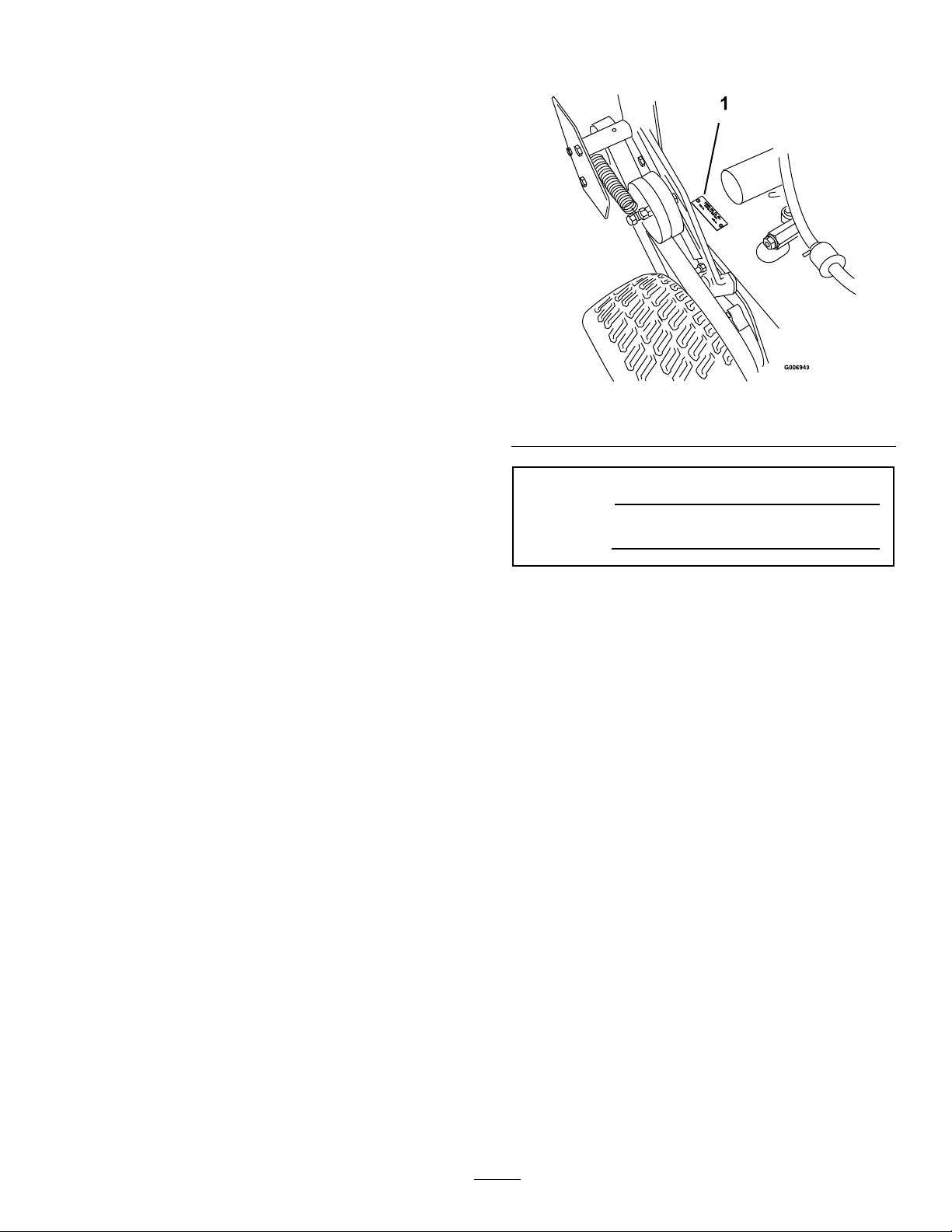
Figure1
1.Modelandserialnumberlocation
ModelNo.
SerialNo.
AllExmarkequipmentdealersanddistributorsare
keptinformedofthelatestmethodsofservicing
andareequippedtoprovidepromptandefcient
serviceintheeldorattheirservicestations.They
carryamplestockofservicepartsorcansecurethem
promptlyforyoufromthefactory.
AllExmarkpartsarethoroughlytestedandinspected
beforeleavingthefactory,however,attentionis
requiredonyourpartifyouaretoobtainthefullest
measureofsatisfactionandperformance.
Wheneveryouneedservice,genuineExmarkparts,
oradditionalinformation,contactanAuthorized
ServiceDealerorExmarkCustomerServiceandhave
themodelandserialnumbersofyourproductready .
Figure1identiesthelocationofthemodelandserial
numbersontheproduct.Writethenumbersinthe
spaceprovided.
3
Page 4

Contents
Introduction...........................................................3
Safety.....................................................................5
SafetyAlertSymbol.........................................5
SafeOperatingPractices..................................5
SafetyandInstructionalDecals.......................9
Specications.......................................................12
ModelNumbers............................................12
Systems.........................................................12
Dimensions...................................................13
TorqueRequirements....................................13
ProductOverview................................................14
Operation.............................................................14
Controls........................................................14
Pre-Start........................................................16
OperatingInstructions..................................16
Transporting.................................................18
Maintenance.........................................................19
RecommendedMaintenanceSchedule(s)...........19
PeriodicMaintenance.......................................20
CheckEngineOilLevel.................................20
CheckMowerBlades.....................................20
CheckSafetyInterlockSystem.......................21
CheckforLooseHardware............................21
ServiceAirCleaner........................................21
ChangeEngineOil........................................22
CheckTirePressures.....................................22
CheckConditionOfBelts..............................22
LubricateGreaseFittings...............................22
CheckSparkPlugs.........................................23
CheckGreaseLevel,InputandOutput
ShaftBearingWearonPeerless
Transmission.............................................23
ThreadLockingAdhesives.............................24
MobilHTSGrease(OrFood-Grade
Anti-seize).................................................24
Copper-BasedAnti-seize..............................24
DielectricGrease...........................................24
Adjustments.....................................................25
AdjustingtheCuttingHeight.........................25
AdjustingtheAxlePosition............................26
AdjustingtheNumberofSpacersbelow
CasterSupportHub...................................27
AdjustingtheCuttingHeightwithBlade
Spacers......................................................27
TransmissionBeltAdjustment.......................28
WheelDriveBeltPulleyScrapers...................28
EnginetoMowerDeckBelt...........................28
BladeBrakeAdjustment................................29
BeltGuideAdjustment..................................30
BrakeandWheelDriveLinkage
Adjustment...............................................30
ShifterLeverAdjustment...............................32
ShifterDetentAdjustment.............................33
PTOSafetySwitchAdjustment......................33
HandleHeightAdjustment............................33
WheelDriveSpringTension
Adjustment...............................................33
Cleaning...........................................................34
CleanEngineandExhaustSystem
Area..........................................................34
RemoveEngineShroudsandCleanCooling
Fins...........................................................34
CleanDebrisFromMachine..........................35
CleanGrassBuild-UpUnderDeck................35
WasteDisposal..............................................35
Troubleshooting...................................................36
Schematics...........................................................38
4
Page 5

Safety
Safety
SafetyAlertSymbol
ThisSafetyAlertSymbol(Figure2)isusedbothin
thismanualandonthemachinetoidentifyimportant
safetymessageswhichmustbefollowedtoavoid
accidents
Thissymbolmeans:ATTENTION!BECOME
ALERT!YOURSAFETYISINVOLVED!
Figure2
1.Safetyalertsymbol
Thesafetyalertsymbolappearsaboveinformation
whichalertsyoutounsafeactionsorsituations
andwillbefollowedbythewordDANGER,
WARNING,orCAUTION.
DANGER:Whitelettering/Redbackground.
Indicatesanimminentlyhazardoussituationwhich,if
notavoided,Willresultindeathorseriousinjury.
WARNING:Blacklettering/Orangebackground.
Indicatesapotentiallyhazardoussituationwhich,if
notavoided,Couldresultindeathorseriousinjury.
CAUTION:Blacklettering/Yellowbackground.
Indicatesapotentiallyhazardoussituationwhich,if
notavoided,Mayresultinminorormoderateinjury.
•Neverletchildrenoruntrainedpeopleoperate
orservicetheequipment.Localregulationsmay
restricttheageoftheoperator.
•Onlyadultsandmatureteenagersshouldoperate
amower,andevenmatureteenagersshouldhave
adultsupervision.Besureateenager:
1.hasreadandunderstandstheOperator’s
Manualandrecognizestherisksinvolved;
2.issufcientlymaturetousecaution;and
3.isofsufcientsizeandweighttooperate
thecontrolscomfortablyandtomanagethe
mowerwithouttakingrisks.
•Theowner/usercanpreventandisresponsible
foraccidentsorinjuriesoccurringtohimselfor
herself,otherpeopleorproperty.
Preparation
•Evaluatetheterraintodeterminewhataccessories
andattachmentsareneededtoproperlyand
safelyperformthejob.Onlyuseaccessoriesand
attachmentsapprovedbyExmark.
•Wearappropriateclothingincludingsafetyglasses,
substantialfootwear,longtrousers,andhearing
protection.DoNotoperatewhenbarefootor
whenwearingopensandals.Longhair,loose
clothingorjewelrymaygettangledinmoving
parts.
CAUTION
Thismanualusestwootherwordstohighlight
information.Importantcallsattentiontospecial
mechanicalinformationandNoteemphasizes
generalinformationworthyofspecialattention.
SafeOperatingPractices
Training
•ReadtheOperator’sManualandothertraining
material.Iftheoperator(s)ormechanic(s)can
notreadEnglishitistheowner’sresponsibilityto
explainthismaterialtothem.
•Becomefamiliarwiththesafeoperationofthe
equipment,operatorcontrols,andsafetysigns.
•Alloperatorsandmechanicsshouldbetrained.
Theownerisresponsiblefortrainingtheusers.
Thismachineproducessoundlevelsinexcess
of85dBAattheoperator’searandcancause
hearinglossthroughextendedperiodsof
exposure.
Wearhearingprotectionwhenoperatingthis
machine.
•Inspecttheareawheretheequipmentistobe
usedandremoveallrocks,toys,sticks,wires,
bones,andotherforeignobjectswhichcanbe
thrownbythemachineandmaycausepersonal
injurytotheoperatororbystanders.
5
Page 6

Safety
DANGER
Incertainconditionsgasolineisextremely
ammableandvaporsareexplosive.
Areorexplosionfromgasolinecanburn
you,others,andcausepropertydamage.
•Fillthefueltankoutdoorsonlevelground,
inanopenarea,whentheengineiscold.
Wipeupanygasolinethatspills.
•Neverrellthefueltankordrainthe
machineindoorsorinsideanenclosed
trailer.
•DoNotllthefueltankcompletelyfull.
Fillthefueltanktothebottomoftheller
neck.Theemptyspaceinthetankallows
gasolinetoexpand.Overllingmayresult
infuelleakageordamagetotheengineor
emissionsystem(ifequipped).
•Neversmokewhenhandlinggasoline,and
stayawayfromanopenameorwhere
gasolinefumesmaybeignitedbyspark.
•Storegasolineinanapprovedcontainer
andkeepitoutofthereachofchildren.
•Addfuelbeforestartingtheengine.Never
removethecapofthefueltankoradd
fuelwhenengineisrunningorwhenthe
engineishot.
DANGER
Incertainconditionsduringfueling,static
electricitycanbereleasedcausingaspark
whichcanignitegasolinevapors.Areor
explosionfromgasolinecanburnyouand
othersandcausepropertydamage.
•Alwaysplacegasolinecontainersonthe
groundawayfromyourvehiclebefore
lling.
•DoNotllgasolinecontainersinsidea
vehicleoronatruckortrailerbedbecause
interiorcarpetsorplastictruckbedliners
mayinsulatethecontainerandslowthe
lossofanystaticcharge.
•Whenpractical,removegas-powered
equipmentfromthetruckortrailerand
refueltheequipmentwithitswheelson
theground.
•Ifthisisnotpossible,thenrefuelsuch
equipmentonatruckortrailerfroma
portablecontainer,ratherthanfroma
gasolinedispensernozzle.
•Ifagasolinedispensernozzlemustbe
used,keepthenozzleincontactwiththe
rimofthefueltankorcontaineropening
atalltimesuntilfuelingiscomplete.
•Iffuelisspilled,DoNotattempttostart
theengine.Moveawayfromtheareaof
thespillandavoidcreatinganysourceof
ignitionuntilfuelvaporshavedissipated.
•DoNotoperatewithoutentireexhaust
systeminplaceandinproperworking
condition.
WARNING
Gasolineisharmfulorfatalifswallowed.
Long-termexposuretovaporshascaused
cancerinlaboratoryanimals.Failuretouse
cautionmaycauseseriousinjuryorillness.
•Avoidprolongedbreathingofvapors.
•Keepfaceawayfromnozzleandgas
tank/containeropening.
•Keepawayfromeyesandskin.
•Neversiphonbymouth.
•Checkthattheoperator’spresencecontrols,
safetyswitches,andshieldsareattachedand
functioningproperly.DoNotoperateunlessthey
arefunctioningproperly.
6
Page 7

Safety
Operation
WARNING
Operatingengineparts,especiallythemufer,
becomeextremelyhot.Severeburnscanoccur
oncontactanddebris,suchasleaves,grass,
brush,etc.cancatchre.
•Allowengineparts,especiallythemufer,to
coolbeforetouching.
•Removeaccumulateddebrisfrommufer
andenginearea.
•Installandmaintaininworkingordera
sparkarresterbeforeusingequipment
onforest-covered,grass-covered,or
brush-coveredunimprovedland.
WARNING
Engineexhaustcontainscarbonmonoxide,
whichisanodorlessdeadlypoisonthatcankill
you.
DoNotrunengineindoorsorinasmallconned
areawheredangerouscarbonmonoxidefumes
cancollect.
damageandmakerepairsbeforerestarting
andoperatingthemower).
–Beforeclearingblockages.
–Wheneveryouleavethemower.
•Stopengine,waitforallmovingpartstostop,and
engageparkingbrake:
–Beforerefueling.
–Beforedumpingthegrasscatcher.
–Beforemakingheightadjustments.
WARNING
Hands,feet,hair,clothing,oraccessoriescan
becomeentangledinrotatingparts.Contact
withtherotatingpartscancausetraumatic
amputationorseverelacerations.
•DoNotoperatethemachinewithout
guards,shields,andsafetydevicesin
placeandworkingproperly.
•Keephands,feet,hair,jewelry,orclothing
awayfromrotatingparts.
•DONOToperatethemowerwhenpeople,
especiallychildren,orpetsareinthearea.
•Operateonlyindaylightorgoodarticiallight,
keepingawayfromholesandhiddenhazards.
•Besurealldrivesareinneutralandparkingbrake
isengagedbeforestartingengine.
•Neverraisedeckwithbladesrunning.
•Neveroperatethemowerwithdamagedguards,
shields,orcovers.Alwayshavesafetyshields,
guards,switchesandotherdevicesinplaceandin
properworkingcondition.
•Nevermowwiththedischargedeectorraised,
removedoralteredunlessthereisagrass
collectionsystemormulchkitinplaceand
workingproperly.
•DoNotchangetheenginegovernorsettingor
overspeedtheengine.
•Stopengine,waitforallmovingpartstostop,
removekeyandengageparkingbrake:
–Beforechecking,cleaningorworkingonthe
mower.
–Afterstrikingaforeignobjectorabnormal
vibrationoccurs(inspectthemowerfor
•Bealert,slowdownandusecautionwhenmaking
turns.Lookbehindandtothesidebefore
changingdirections.
•Stoptheblades,slowdown,andusecautionwhen
crossingsurfacesotherthangrassandwhen
transportingthemowertoandfromtheareato
bemowed.
•Beawareofthemowerdischargepathanddirect
dischargeawayfromothers.
•DoNotoperatethemowerundertheinuence
ofalcoholordrugs.
•Useextremecarewhenloadingorunloadingthe
machineintoatrailerortruck.
•Usecarewhenapproachingblindcorners,shrubs,
trees,orotherobjectsthatmayobscurevision.
SlopeOperation
UseExtremecautionwhenmowingand/orturning
onslopesaslossoftractionand/ortip-overcould
occur.Theoperatorisresponsibleforsafeoperation
onslopes.
7
Page 8

Safety
DANGER
Operatingonwetgrassorsteepslopescan
causeslidingandlossofcontrol.Lossofcontrol
and/orlossofoperator’sfootingcouldresultina
fallwithanarmorleggettingunderthemower
orenginedeckwhichmayresultinserious
injury,deathordrowning.
•Mowacrossslopes,neverupanddown.
•DoNotmowslopeswhengrassiswet.
•DoNotmowneardrop-offsornearwater.
•DoNotmowslopesgreaterthan20degrees.
•Reducespeedanduseextremecautionon
slopes.
•Avoidsuddenturnsorrapidspeedchanges.
•Seeinsidethebackcovertodeterminethe
approximateslopeangleoftheareatobemowed.
•Removeormarkobstaclessuchasrocks,tree
limbs,etc.fromthemowingarea.Tallgrasscan
hideobstacles.
•Watchforditches,holes,rocks,dipsandrisesthat
changetheoperatingangle,asroughterraincould
overturnthemachine.
•Avoidsuddenstartswhenmowinguphillbecause
themowermaytipbackwards.
•Beawarethatoperatingonwetgrass,acrosssteep
slopesordownhillmaycausethemowertolose
traction.Lossoftractiontothedrivewheelsmay
resultinslidingandalossofbrakingandsteering.
•Keepengineandengineareafreefrom
accumulationofgrass,leaves,excessivegrease
oroil,andotherdebriswhichcanaccumulate
intheseareas.Thesematerialscanbecome
combustibleandmayresultinare.
•LetenginecoolbeforestoringandDoNotstore
nearameoranyenclosedareawhereopenpilot
lightsorheatappliancesarepresent.
•Shutofffuelwhilestoringortransporting.Do
Notstorefuelnearamesordrainindoors.
•Parkmachineonlevelground.Neverallow
untrainedpersonneltoservicemachine.
•Usejackstandstosupportcomponentswhen
required.
•Carefullyreleasepressurefromcomponentswith
storedenergy.
•Usecarewhencheckingblades.Wraptheblade(s)
orweargloves,andusecautionwhenservicing
them.Onlyreplacedamagedblades.Never
straightenorweldthem.
•Keephandsandfeetawayfrommovingparts.
Ifpossible,DoNotmakeadjustmentswiththe
enginerunning.
•Keepallguards,shieldsandallsafetydevicesin
placeandinsafeworkingcondition.
•Checkallboltsfrequentlytomaintainproper
tightness.
•Frequentlycheckforwornordeteriorating
componentsthatcouldcreateahazard.
•Alwaysavoidsuddenstartingorstoppingona
slope.Iftireslosetraction,disengagetheblades
andproceedslowlyofftheslope.
•Followthemanufacturer’srecommendationsfor
wheelweightsorcounterweightstoimprove
stability.
•Useextremecarewithgrasscatchersor
attachments.Thesecanchangethestabilityofthe
machineandcauselossofcontrol.
MaintenanceandStorage
•Disengagedrives,lowerimplement,setparking
brake,stopengineandremovekeyordisconnect
sparkplugwire.Waitforallmovementtostop
beforeadjusting,cleaningorrepairing.
WARNING
Removingstandardoriginalequipmentparts,
orusingnon-Exmarkreplacementpartsand
accessoriesmayalterthewarranty,traction,and
safetyofthemachine.Failuretouseoriginal
Exmarkpartscouldcauseseriousinjuryor
death.
Replaceallpartsincluding,butnotlimitedto
tires,belts,andbladeswithoriginalExmark
parts.
8
Page 9
SafetyandInstructionalDecals
Safety
•Keepallsafetysignslegible.Removeallgrease,
dirtanddebrisfromsafetysignsandinstructional
labels.
•Replaceallworn,damaged,ormissingsafety
signs.
•Whenreplacementcomponentsareinstalled,be
surethatcurrentsafetysignsareafxedtothe
replacedcomponents.
•Ifanattachmentoraccessoryhasbeeninstalled,
makesurecurrentsafetysignsarevisible.
1-303508
•Newsafetysignsmaybeobtainedfrom
yourauthorizedExmarkequipmentdealeror
distributororfromExmarkMfg.Co.Inc.
•Safetysignsmaybeafxedbypeelingoffthe
backingtoexposetheadhesivesurface.Apply
onlytoaclean,drysurface.Smoothtoremove
anyairbubbles.
•Familiarizeyourselfwiththefollowingsafetysigns
andinstructionlabels.Theyarecriticaltothesafe
operationofyourExmarkcommercialmower.
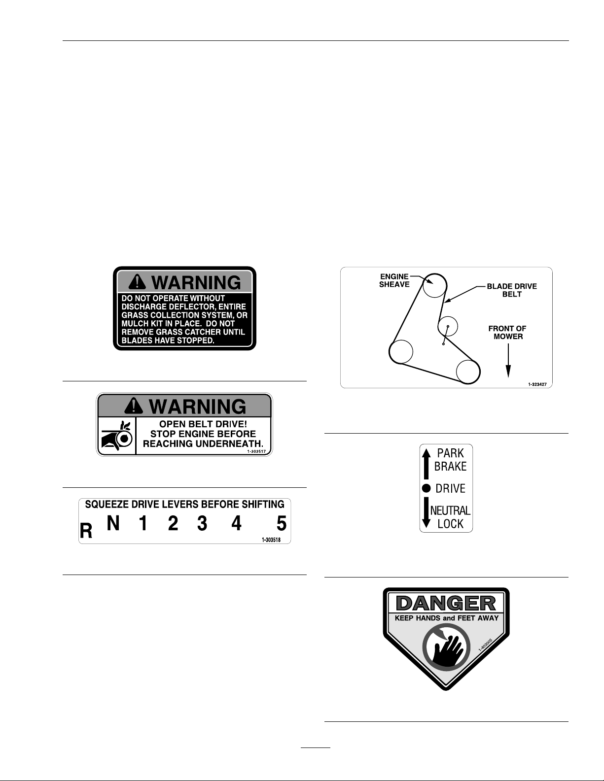
1-323427
32inchand36inchUnitsOnly
1-303517
1-323550
1-303518
PistolGripHandleUnitsOnly
1-403005
9
Page 10

Safety
1-403143
98-5954
103–2076
103-2244
ECSUnitsOnly
103-1623
ECSUnitsOnly
103-1798
103-2245
ECSUnitsOnly
10
Page 11
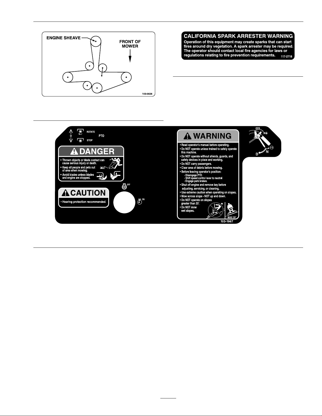
103-5626
48inchDeckUnitsOnly
Safety
117–2718
103-1967
PistolGripUnitsOnly
11
Page 12

Specications
Specications
ModelNumbers
SerialNos:850,000andHigher
M16KA322PM16KA362PM16KA362M16KA483PM16KA483M16KA322PCAM16KA362CAM16KA483CA
Systems
Engine
•EngineSpecications:SeeyourEngineOwner’s
Manual
•RPM:FullSpeed:3600(NoLoad)
FuelSystem
•Capacity:5.0gal.(18.9L)
•TypeofFuel:Regularunleadedgasoline,87
octaneorhigher;containingnomorethan10%
methanolorethanol.
•FuelFilter:ReplaceableIn-line
•FuelShut-OffValve:1/4turnincrements
SafetyInterlockSystem
Operatormusthavethetransmissioninneutraland
PTOdisengagedtostartengine.ReleaseofOperator
PresenceControl(OPC)leverswillcauseengineto
stopiftransmissionisnotinneutraland/orPTO
isengaged.
Steering/BrakeControls
Fingertipdrivecontrolleversprovideindependent
controloftraction,braking,andneutraltoeachdrive
wheelformoving,stopping,andpowerturning.
Parkingbrakesareengagedbylockingdrivecontrol
leversinthe“brake”position.
Transmission
•Peerless700-070A,vespeedsforwardandone
reverse.
•Speedrange:
–1st:2.0mph(3.22km/hr)
–2nd:2.7mph(4.35km/hr)
–3rd:3.5mph(5.63km/hr)
–4th:4.1mph(6.60km/hr)
–5th:6.2mph(9.98km/hr)
–Reverse:3.1mph(4.99km/hr)
WheelDriveSystem
BandeddoubleA-SectionV-belts,singletop-side
idlersandreplaceablebolt-ondrivesheavesandbrake
drums.(SingleB-SectionV -beltsforthe32inch
Model)
Tires&Wheels
Drive
Pneumatic(Air-Filled)
3236&48
Quantity
Tread
Size13x5.00-613x6.50-69x3.50-4
PlyRating
Pressure
Bearings
222
TurfSaverTurfMasterSmooth
44
14psi
(97kPa)
Replaceable
Ball
14psi
(97kPa)
Replaceable
Ball
Front
Caster
SemiPneumatic
AllDecks
Replaceable
Roller
12
Page 13

Specications
CuttingDeck
•CuttingWidth:
–32inchDeck:31.75inches(80.7cm)
–36inchDeck:35.38inches(89.9cm)
–48inchDeck:47.25inches(120.0cm)
•Discharge:Side
•BladeSize:
–32inchDeck:16.25inches(41.3cm)—
Quantity:2
–36inchDeck:18.00inches(45.7cm)—
Quantity:2
–48inchDeck:16.25inches(41.3cm)—
Quantity:3
•DeckDrive:Manualengagementofbeltwith
over-centerlock.Bladebelttensionisadjustable
viaturnbuckle.
•BladeBrake:Whenthebladeengagementcontrol
ismovedtothedisengagedpositionafriction
brakepadstopstherotationoftheblades.
•DeckMounting:Bolteddirectlytoenginedeck.
•DeckDepth:
OverallLength:
32inch
Deck
Standard
PistolGrip
Handles
ECS
Handles
78.0inches
(198.1cm)
77.3inches
(196.3cm)
36inch
Deck
78.0inches
(198.1cm)
77.3inches
(196.3cm)
48inch
Deck
73.0inches
(185.4cm)
72.3inches
(183.6cm)
OverallHeight:
StandardPistolGrip
Handles
ECSHandles
40.0inches(101.6cm)
42.1inches(106.9cm)
TreadWidth:(OutsidetoOutsideof
Tires,Widthwise)
32inch
Deck
Standard
PistolGrip
&ECS
Handles
32.1inches
(81.4cm)
36inch
Deck
35.6inches
(90.4cm)
48inch
Deck
35.6inches
(90.4cm)
–32inchDeck:5.0inches(12.7cm)
–36inchDeck:5.0inches(12.7cm)
–48inchDeck:5.0inches(12.7cm)
•CuttingHeightAdjustment:
Adjustsfrom1inch(2.5cm)to41/4inches(10.8
cm)in1/4inch(6.4mm)orsmallerincrements
byvariousadjustmentsofcasterspacers,blade
spacers,andaxleheight.
Dimensions
OverallWidth:
32inch
Deck
Deector
Up
Deector
Down
32.7inches
(83.1cm)
43.3inches
(110.0cm)
36inch
Deck
36.4inches
(92.5cm)
47.0inches
(119.4cm)
48inch
Deck
48.1inches
(122.2cm)
57.9inches
(147.1cm)
CurbWeight:
32inch
Deck
Standard
PistolGrip
Handles
ECS
Handles
420lb
(191kg)
435lb
(197kg)
TorqueRequirements
BoltLocation
Blade/CutterHousing
SpindleBolt
CasterBracketMounts
MowerDeck/Engine
DeckMount
EngineMountingBolts
TransmissionShifterLever
Nut
36inch
Deck
430lb
(195kg)
446lb
(202kg)
Torque
75-80ft-lb(102-109N-m)
30-35ft-lb(41-48N-m)
30-35ft-lb(41-48N-m)
17-23ft-lb(23-31N-m)
30-35ft-lb(41-48N-m)
48inch
Deck
475lb
(215kg)
490lb
(222kg)
13
Page 14
Operation
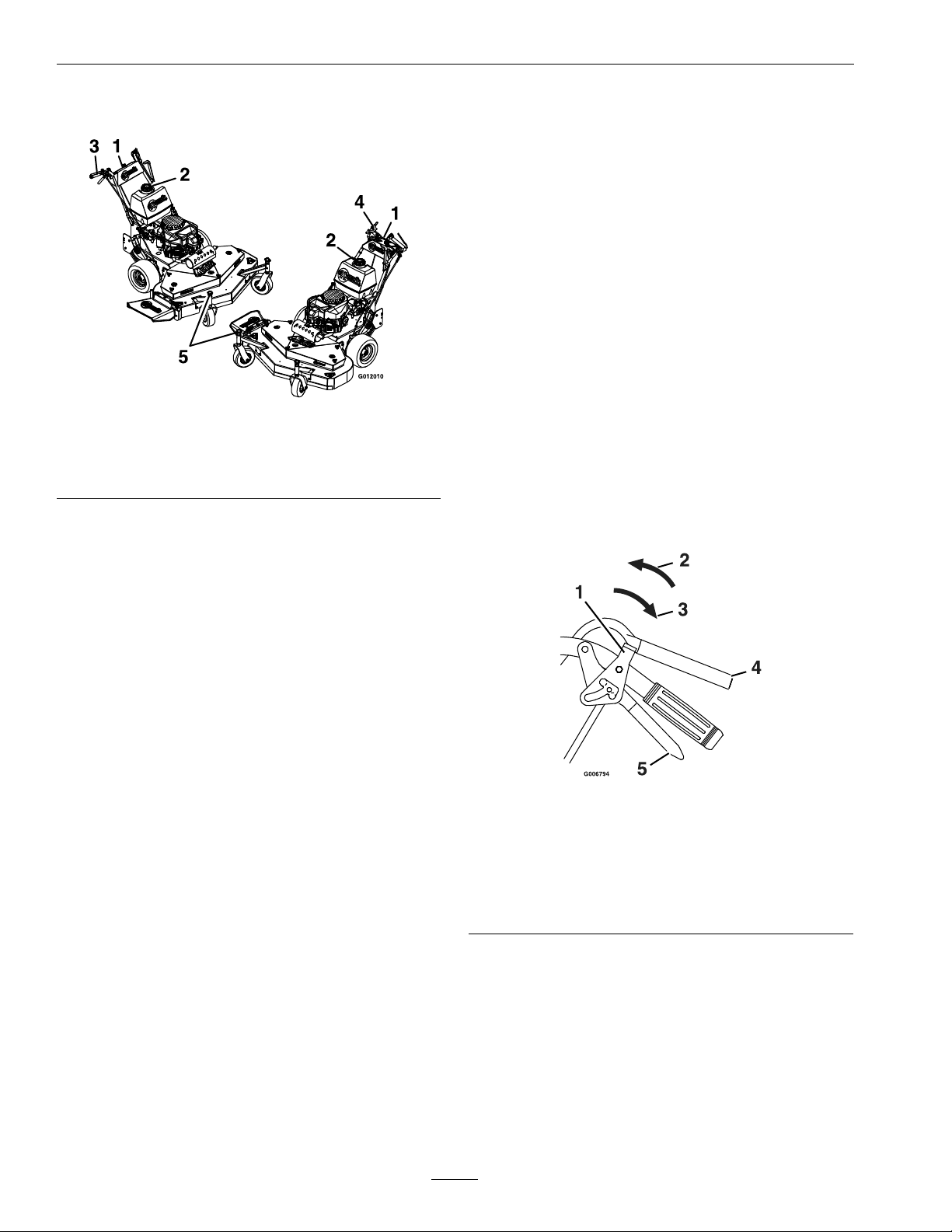
ProductOverview
Figure3
1.Controls4.ECSHandles
2.FuelCap5.BladeSpacers
3.PistolGripHandles
Operation
Note:Determinetheleftandrightsidesofthe
machinefromthenormaloperatingposition.
Controls
OperatorPresenceControl(OPC)
Levers
Locatedontheupperhandleassemblydirectlyabove
thehandlegrips.
Whentheseleversaredepressed,theOPCsystem
sensesthattheoperatorisinthenormaloperator’s
position.Whentheleversarereleased,theOPC
systemsensesthattheoperatorhasmovedfromthe
normaloperatingpositionandwillkilltheengineif
eitherthetransmissionshiftleverisnotintheneutral
positionorthePTOisengaged(see
Figure5).
Figure4and
PistolGripHandle
1.NeutralLock/ParkBrakeLatch
2.Rotatelatchforwardforparkbrakeposition
3.Rotatelatchbackforneutrallockposition
4.OPCLever
5.DriveLever
14
Figure4
Page 15

Operation
ChokeControl
Locatedonthefrontleftcornerofthefueltank
support.
Chokeisusedtoaidinstartingacoldengine.The
chokecontrolispulledouttobeinthe“ON”position
andpushedintobeinthe“OFF”position.DoNot
runawarmenginewithchokeinthe“ON”position.
ThrottleControl
Figure5
ECSHandle
1.OPCLever
2.Rotatelatchforneutrallockandparkbrakepositions
3.NeutralLockLatch/ParkBrakeLatch
4.DriveLever
DriveLevers
Locatedoneachsideoftheupperhandleassembly
aheadofandbelowthehandlegrips(seeFigure4
andFigure5).
Theseleversindividuallycontrolclutchingactionof
thewheeldrivebeltsandbrakes.Whenthedrive
leversareallthewaydown,thebrakesdisengageand
thewheeldrivebeltsengage
Graduallysqueezingtheleftorrighthanddrivelever
disengagesthewheeldrivebelts,causingthelefthand
orrighthandwheeltoslowdownuntiltheyreach
neutralorstop.Thismakesthemachineturntothe
leftorrightrespectively.Squeezingfurtherengages
theparkbrakes.Thesharpnessoftheturnvariesby
howmuchtheleverissqueezed.Forstraightahead
motion,smoothlyreleasebothdriveleverstoengage
bothdrivewheelssimultaneously.
Locatedontheonthecontrolconsolerightside.
Thethrottleisusedtocontrolenginespeed.Moving
thethrottlecontrolforwardwillincreaseengine
speedandmovingittotherearwilldecreaseengine
speed.Movingthethrottleforwardintothedetent
isfullposition.
TransmissionShiftLever
Locatedunderthecontrolconsoleandbehindthe
fueltank.
Itshiftsthe5-speedtransmissionintoveforward
gears,neutralandreverse.Shifttransmissiononly
whendriveleversareintheneutralposition.Shifting
withoutdriveleversinneutralmaycausedamageto
thetransmission.
Note:Reverseis“reverseassist”only,meaningwhen
thetransmissionisinreverse,theoperatorhastopull
theunitbackwardto“assist”withthemovementof
theunit.
“Off-Run”Switch
Locatedonthecontrolconsole.
Turnthekeytothe“Run”positiontoallowthe
enginetobestarted.Turnthekeytothe“Off”
positiontoshutengineoff.
NeutralLock/ParkBrakeLatches
•ForPistolGripHandles:Locatedonhandles
aheadofthegrips.
•ForECSHandles:Locatedontheupperhandle
assemblyontheendsofthehandlegrips.
Thelatchesallowtheoperatortolockthedrivelevers
ina“neutral”positionwhereneitherthewheeldrive
beltsnorthebrakesengageorina“parkbrake”
positionwherethewheeldrivebeltsarenotengaged
andtheparkbrakeisengaged(seeFigure4and
Figure5).
FuelShut-OffValve
Locatedinthefuellinemidwaybetweenthetank
andengine.
Thefuelshut-offvalveisusedtoshutoffthe
owoffuelwhenparkinginsideabuilding,during
transportationtoandfromthejobsites,andwhen
themachinewillnotbeusedforafewdays.
Rotatevalve1/4turnclockwisetoshutfueloff.
Rotatevalve1/4turncounterclockwisetoturnfuel
on.
15
Page 16

Operation
Pre-Start
Fillfueltankonlevelground.Forbestresultsuse
onlyclean,freshregulargradeunleadedgasolinewith
anoctaneratingof87orhigher.
Important:Neverusemethanol,gasoline
containingmethanol,gasoholcontainingmore
than10%ethanol,premiumgasoline,orwhite
gasbecausethefuelsystemcouldbedamaged.
DoNotaddoiltogasoline.
DoNotoverllfueltank.Fillthefueltanktothe
bottomofthellerneck.Theemptyspaceinthe
tankallowsgasolinetoexpand.Overllingmayresult
infuelleakageordamagetotheengineoremission
system(ifequipped).
Makesureyouunderstandthecontrols,their
locations,theirfunctions,andtheirsafety
requirements.
RefertotheMaintenancesectionandperformallthe
necessaryinspectionandmaintenancesteps.
OperatingInstructions
PTOEngagement
DANGER
Therotatingbladesunderthemowerdeckare
dangerous.Bladecontactcancauseserious
injuryorkillyou.
DoNotputhandsorfeetunderthemoweror
mowerdeckwhenthebladesareengaged.
DANGER
Anuncovereddischargeopeningwillallow
objectstobethrowninanoperator’sor
bystander’sdirection.Also,contactwiththe
bladecouldoccur.Thrownobjectsorblade
contactcancauseseriousinjuryordeath.
Neveroperatethemowerwiththedischarge
deectorraised,removed,oralteredunlessthere
isagrasscollectionsystemormulchkitinplace
andworkingproperly.
ThePTOswitchengagesthecuttingblades.Besure
thatallpersonsareclearofmowerdeckanddischarge
areabeforeengagingthePTO.
OpentheFuelShut-OffValve
Rotatethevalve1/4turncounterclockwisetoturn
fuelon.
StartingtheEngine
Note:Alwaysengagetheleftandrightneutral
lock/parkbrakelatchesinthe“parkbrake”position
whenstartingtheengine
1.Onacoldengine,placethethrottlemidway
betweenthe“Slow”and“Fast”positionsand
placethechokeinthe“On”position.Onawarm
engine,placethethrottlelevermidwaybetween
“Slow”and“Fast”positionsandleavethechoke
inthe“Off”position.
2.Turnignitionswitchto“Run”position.Pullthe
recoilropetostartengine.
3.Onacoldengine,graduallyreturnchoketothe
“Off”positionafterenginestartsandwarmsup.
Note:Kawasakienginesgenerallyneedtobe
“choked”evenwhenwarm.
1.Setthrottleto“MIDW AY”position.
2.PushthePTOleverforwardtoengageblades.
3.Placethethrottleinthe“FAST”positiontobegin
mowing.
DisengagingthePTO
1.Setthrottleto“MIDW AY”position.
2.Pullthebladeengagementlevertothefull
rearwardpositiontodisengagetheblades
StoppingtheEngine
1.Bringtheunittoafullstop.
2.Lockdriveleversin“parkbrake”position.
3.DisengagethePTO.
4.Movetransmissionshiftleverto“neutral”.
5.Placethethrottlemidwaybetweenthe“SLOW”
and“FAST”positions.
6.Allowtheenginetorunforaminimumof15
seconds,thenturntheignitionswitchtothe
“OFF”positiontostoptheengine.
16
Page 17

7.Removethekeytopreventchildrenorother
unauthorizedpersonsfromstartingengine.
8.Closethefuelshut-offvalvewhenthemachine
willnotbeinuseforafewdays,when
transporting,orwhentheunitisparkedinside
abuilding.
DrivingtheMachine
DriveLever/NeutralLock/ParkBrakeLatch
Operation
•ForPistolGripHandles
Tolockthedriveleversin“neutral”,squeezethe
driveleversbacktotheneutralposition.Place
thumbsontheupperportionoftheneutral
lock/parkbrakelatchesandmovethemtothe
rear.Releasethedrivelevers.
Tolocktheleversin“parkbrake”,squeezethe
driveleversbacktothebrakeposition.Place
thumbsontheupperportionoftheneutral
lock/parkbrakelatchesandmovethemtothe
front.Releasethedrivelevers(see
Figure6)
Operation
Figure6
1.Latchisinthedrive
position
2.Rotateforwardforpark
brakeposition
3.Rotatebackforneutral
lockposition
4.Parkbrake9.Reverse—squeezedrive
5.Fullspeedforward
6.Neutrallock
7.Forward—releasedrive
lever
8.Neutral—holdinthis
position
lever
CAUTION
Iftheneutrallock/parkbrakelatchesarenot
completelyengagedthedriveleverscould
unexpectedlyslipintotheforwarddrive
position.Ifthedriveleversslipintothedrive
position,theunitcouldlurchforwardand
causeinjuryorpropertydamage.
Besurethepinsprotrudingthroughtheslots
ofeachneutrallocklatcharecompletely
engagedintherearslotofeachlatch.
Toplacethedriveleversinthedriveposition,
rmlyholdthedrivelevers,placethumbsonthe
upperportionoftheneutrallock/parkbrake
latchesandmovethemoutofthe“neutral”or
the“parkbrake”position.Slowlyandsmoothly
releasethedrivelevers.
•ForECSHandles
Tolockthedriveleversin“neutrallock”,squeeze
thedriveleverstothe“neutral”position.See
Figure7position2.Placethumbsontheinner
thumblobeoftheneutrallock/parkbrakelatches
androtatethemtothe“neutral”position.See
Figure7position3.Releasethedrivelevers.
Tolockthedriveleversin“parkbrake”,squeeze
thedriveleversfarthertothe“brake”position.
Placethumbsontheinnerthumblobeofthe
neutrallock/parkbrakelatchesandrotatethem
tothe“park”position.See
Figure7position4.
Releasedrivelevers.
CAUTION
Iftheneutrallock/parkbrakelatchesarenot
completelyengagedthedriveleverscould
unexpectedlyslipintotheforwarddrive
position.Ifthedriveleversslipintothedrive
position,theunitcouldlurchforwardand
causeinjuryorpropertydamage.
Besurethedriveleversaresecurelyseatedat
thebottomofthe“neutral”or“park”areasof
theneutrallocklatches.
17
Page 18

Operation
Toplacethedriveleversinthe“drive”position,
slightlysqueezethedriveleverswhileplacing
thumbsontheouterthumblobeoftheneutral
lock/parkbrakelatches(ortheindexngeron
thefrontlobe)androtatethemfromunderthe
drivelevers.Slowlyandcarefullyreleasethedrive
levers.See
1.DriveLeverindrive
position
2.DriveLeverinneutral
position
Figure7position1.
Figure7
3.DriveLeverlockedin
neutralposition
4.DriveLeverlockedin
parkposition
Smoothlyreleasebothdriveleverstoengagedrive
wheels.
Pulltheunitbackwardto“assist”withthemovement
oftheunit.
Tostop,squeezedriveleversallthewaybackto
engagethebrakes.Movetheneutrallocklatchesinto
the“parkbrake”positionandreleasedrivelevers.
Movethespeedcontrollevertotheneutralposition.
ChangingGears
Whenchanginggears,alwayssqueezedriveleversto
theneutralposition.Theshiftlevermaybemoved
withakneeorbyhand(engagetheneutrallock
latchesifshiftingbyhand).
Note:Reversegearis“reverseassist”only,the
operatormustpulltheunitbackwards.
Transporting
TransportingaUnit
WARNING
DrivingForward
1.Withdriveleversinthe“neutral”or“parkbrake”
position,shifttransmissionintodesiredgear.
2.Squeezebothdriveleversandmovebothneutral
lock/parkbrakelatchesfromthe“neutral”or
“parkbrake”positiontothe“drive”position.
3.Tomoveforwardinastraightline,smoothly
releasebothdriveleverstoengagedrivewheels.
Toturnleftorright,squeezetherighthanddrive
levertoturnrightandthelefthanddrivelever
toturnleft.
Squeezedriveleversallthewaybacktoengage
brakes.Moveneutrallock/parkbrakelatchesinto
the“parkbrake”positionandreleasedrivelevers.
Shifttransmissionintoneutral.
DrivinginReverse
Note:Reversegearisreverseassistonly,theoperator
mustpulltheunitbackwards.
Tomoverearward,squeezethedriveleverstoneutral
positionandmovetheshiftertothe“R”.
Loadingthemowerontoatrailerwithoutstrong
enoughorproperlysupportedrampscouldbe
dangerous.Therampscouldcollapsecausing
theunittofall,whichcouldcauseinjury.
•Useproperrampsthataresecuredtothe
truckortrailer.
•Keepfeetandlegsoutfromundertheunit
whenloadingandunloading.
•Ifnecessary,useassistancewhenloading.
Besurethefuelshut-offvalveisclosed.
Useaheavydutytrailertotransportthemachine.
Engageneutrallocklatchesandparkbrake,then
blockwheels.
Securelyfastenthemachinetothetrailerwithstraps,
chains,cables,orropes.
DoNotrelysolelyontheparkingbraketoholdthe
machineonthetrailer.
Besurethatthetrailerhasallnecessarylightingand
markingasrequiredbylawanduseasafetychain.
18
Page 19

Maintenance
Note:Determinetheleftandrightsidesofthemachinefromthenormaloperatingposition.
Maintenance
WARNING
Whilemaintenanceoradjustmentsarebeing
made,someonecouldstarttheengine.
Accidentalstartingoftheenginecouldseriously
injureyouorotherbystanders.
Removethekeyfromtheignitionswitch,engage
parkingbrake,andpullthewire(s)offthespark
plug(s)beforeyoudoanymaintenance.Also
pushthewire(s)asidesoitdoesnotaccidentally
contactthesparkplug(s).
RecommendedMaintenanceSchedule(s)
MaintenanceService
Interval
Aftertherst5hours
Beforeeachuseordaily
MaintenanceProcedure
•Changetheengineoil.
•Checktheengineoillevel.
•Checkthemowerblades.
•Checkthesafetyinterlocksystem.
•Checkforloosehardware.
•Greasethefrontcasterwheelbearings.
•Greasefrontcasterpivots.
•Greasethedrivewheels.
•Greasethedrivewheelidlerarm.
•Cleantheengineandexhaustsystemarea.
•Cleanthegrassanddebrisbuild-upfromthemachineandcuttingdeck.
•Cleanthegrassbuild-upfromunderthedeck.
WARNING
Theenginecanbecomeveryhot.T ouchingahot
enginecancausesevereburns.
Allowtheenginetocoolcompletelybefore
serviceormakingrepairsaroundtheenginearea.
Every25hours
Every40hours
Every100hours
Every160hours
Every200hours
•Servicethefoamelement.(Mayneedmoreoftenundersevereconditions.SeetheEngine
Owner’smanualforadditionalinformation.)
•Checkthetirepressures.
•Checktheconditionofthebelts.
•Greasethebrakearm.
•Greasethetransmissionoutputshaftcoupler
•Greasethemowerdeckidlerpivots
•Servicethepaperelement.(Mayneedmoreoftenundersevereconditions.SeetheEngine
Owner’smanualforadditionalinformation.)
•Changetheengineoil.(Mayneedmoreoftenundersevereconditions.)
•Removeengineshroudsandcleancoolingns.
•Checkthesparkplugs.
•Checkgreaselevel,inputandoutputshaftbearingwearonPeerlessTransmission.
•Replacethepaperelement.
Yearly
•Replacegearboxgrease.
19
Page 20

Maintenance
PeriodicMaintenance
CheckEngineOilLevel
ServiceInterval:Beforeeachuseordaily
1.Stopengineandwaitforallmovingpartstostop.
Makesureunitisonalevelsurface.
2.Checkwithenginecold.
3.Cleanareaarounddipstick.Removedipstickand
wipeoiloff.Reinsertthedipstickandpushitall
thewaydownintothetube.DoNotscrewinto
place.Removethedipstickandreadtheoillevel.
4.Iftheoillevelislow ,wipeofftheareaaroundthe
oilllcap,removecapandlltothe“FULL”
markonthedipstick.Useoilasspeciedin
EngineOwner’sManual.DoNotoverll.
Important:DoNotoperatetheenginewiththe
oillevelbelowthe“LOW”(or“ADD”)markon
thedipstick,oroverthe“FULL”mark.
Figure8
1.Springdiscwasher(conetowardsbolthead)
2.Bladebolttorqueto75-80ft-lb(102-109N-m).
ReplacingtheDischarge
CheckMowerBlades
ServiceInterval:Beforeeachuseordaily
1.Stopengine,waitforallmovingpartstostop,and
removekey.Engageparkingbrake.
2.Liftdeckandsecureinraisedpositionasstated
intheCleanGrassBuild-UpUnderDeck
procedure.
3.Inspectbladesandsharpenorreplaceasrequired.
4.Re-installtheblades(iftheywereremoved)and
torquebladeboltsto75-80ft-lb(102-109N-m).
Besurethespringdiscwasherconeisinstalled
towardthebolthead(see
Figure8).
Deector
ServiceInterval:Asrequired
DANGER
Anuncovereddischargeopeningcouldallowthe
lawnmowertothrowobjectsintheoperator’sor
bystander’sdirectionandresultinseriousinjury.
Also,contactwiththebladecouldoccur.
Neveroperatethelawnmowerunlessyouinstall
amulchplate,dischargedeector,orgrass
collectionsystem.
1.Toremoveadamagedorworndischarge
deector,liftthelegofthespringwiththeloop
outofthenotchinthedischargedeectorand
slidetherodoutofthedischargedeector
brackets,anddischargedeector.
2.Toinstallnewdischargedeector,orientthe
springontherodasshowninFigure9.Slidethe
rodthroughthefrontdischargedeectorbracket,
dischargedeector,andreardeectorbracket.
20
Page 21

Maintenance
shiftthetransmissionintogearandreleasethe
OPClevers–theenginemuststop.
3.Again,runtheengineaton-thirdthrottle,move
thetransmissionshifterlevertoneutral,engage
thePTOandreleasetheOPClevers–theengine
muststop.
Note:Ifmachinedoesnotpassanyofthesetests,
donotoperate.ContactyourauthorizedEXMARK
SERVICEDEALER.
Important:Itisessentialthatoperatorsafety
mechanismsbeconnectedandinproper
operatingconditionpriortouseformowing .
CheckforLooseHardware
ServiceInterval:Beforeeachuseordaily
Figure9
1.Rod4.Mowerdeck
2.Spring5.Dischargedeector
3.Dischargedeector
3.Hookthebentendoftherodaroundthefront
dischargedeectorbrackettoretainitfrom
slidingout.Placethelegofthespringwiththe
loopinthenotchinthedischargedeectorto
holdthedischargedeectorinthedownposition
(seeFigure9).
Important:Thedischargedeectormustbe
springloadedinthedownposition.Liftthe
deectoruptotestthatitsnapstothefull
downposition.
bracket
6.Assembledview
CheckSafetyInterlock
System
ServiceInterval:Beforeeachuseordaily
1.Foryoursafety,yourExmarkmowerisequipped
withOperatorPresenceControls,referredtoas
(OPC).WheneitherthePTOisengaged,orthe
transmissionshifterleverisnotinneutralandthe
operatorremovesbothhandsfromthehandles,
themowerenginemuststop.
2.TodetermineiftheOPCisinoperatingcondition,
clearareaofbystanders.Runtheengineat
one-thirdthrottle,thenwiththedriveleversand
neutrallocklatchesinthe“parkbrake”position,
1.Stopengine,waitforallmovingpartstostop,and
removekey.Engageparkingbrake.
2.Visuallyinspectmachineforanyloosehardware
oranyotherpossibleproblem.Tightenhardware
orcorrecttheproblembeforeoperating.
ServiceAirCleaner
ServiceInterval:Every25hours—Service
thefoamelement.(May
needmoreoftenunder
severeconditions.See
theEngineOwner’s
manualforadditional
information.)
Every100hours—Service
thepaperelement.(May
needmoreoftenunder
severeconditions.Seethe
EngineOwner’smanual
foradditionalinformation.)
Every200hours/Yearly
(whichevercomes
rst)—Replacethepaper
element.
1.Stopengine,waitforallmovingpartstostop,and
removekeyorsparkplugwire(s).Engageparking
brake.
2.SeetheEngineOwner’sManualformaintenance
instructions.
21
Page 22

Maintenance
ChangeEngineOil
ServiceInterval:Aftertherst5hours
Every100hours(May
needmoreoftenunder
severeconditions.)
1.Stopengine,waitforallmovingpartstostop,and
removekey.Engageparkingbrake.
2.Drainoilwhileengineiswarmfromoperation.
3.Removetheoildrainplugfromtherighthand
sideoftheengine.Allowoiltodrain,replace
drainplug.
4.Replacetheoillterpertheengineowner’ s
manual.Cleanaroundoillterandunscrewlter
toremove.Beforethenewlterisinstalled,
applyathincoatingofoilonthesurfaceofthe
rubberseal.Turnlterclockwiseuntilrubberseal
contactsthelteradapter,thentightenlteran
additional2/3to3/4turn.
5.Cleanaroundoilllcapandremovecap.Fillto
speciedcapacityandreplacecap.
6.Useoilrecommendedinengineowner’smanual.
DoNotoverll.Starttheengineandcheckfor
leaks.Stopengineandrecheckoillevel.
7.Wipeupanyspilledoilfromenginedeck
mountingsurfaces.
CheckTirePressures
ServiceInterval:Every40hours
1.Stopengine,waitforallmovingpartstostop,and
removekey.Engageparkingbrake.
2.Checktirepressureindrivetires.
3.Inatedrivetiresto12–16psi(83–110kPa).
4.Inatetirestopressuresstatedabove.Measure
thecircumferenceofeachdrivetire.Adjusttire
pressureswithintheaboverangetotrytomake
tirecircumferencesmatchascloselyaspossible.
5.Semi-pneumaticcastertiresDoNotneedtobe
inated.
1.Stopengine,waitforallmovingpartstostop,and
removekey.Engageparkingbrake.
2.Removethemowerdeckbeltshieldtocheck
mowerbladedrivebeltcondition.
3.Lookunderenginedecktocheckthetransmission
drivebeltcondition.
4.Inspectwheeldrivebeltconditions.
5.Checkallidlerarmstobesuretheypivotfreely .
Disassemble,cleanandgreasepivotbushingsif
necessary.
LubricateGreaseFittings
Note:Seechartforserviceintervals.
1.Stopengine,waitforallmovingpartstostop,and
removekey.Engageparkingbrake.
2.LubricatettingswithNGLIgrade#2
multi-purposegungrease.
Refertothefollowingchartforttinglocations
andlubricationschedule.
LubricationChart
Fitting
Locations
1.Front
Caster
Wheel
Bearings
2.Front
Caster
Pivots
3.Drive
Wheels
4.Drive
Wheel
IdlerArm
5.Brake
Arm
Initial
Pumps
12222
2222
18222
2222
2222
NumberofPlacesService
32inch
Deck
36inch
Deck
Interval
48inch
Deck
Daily
Daily
Daily
Daily
40
hours
Note:Amoreuniformcuttingheightmaybe
obtainedwithhighertirepressureonroughterrain.
Alowertirepressureprovidesmoreotation.
CheckConditionOfBelts
ServiceInterval:Every40hours
22
Page 23

Maintenance
LubricationChart(cont'd.)
Fitting
Locations
6.Transmission
Output
Shaft
Coupler
7.Mower
Deck
Idler
Pivots
Initial
Pumps
2222
2111
NumberofPlacesService
Interval
hours
hours
CheckSparkPlugs
ServiceInterval:Every160hours
40
Removesparkplugs,checkconditionandresetgaps,
orreplacewithnewplugs.SeeEngineOwner’ s
Manual.
40
ChangeFuelFilter
ServiceInterval:Asrequired
Afuellterisinstalledinthefuellinebetweenthe
fueltankandtheengine.Replacewhennecessary.
CheckGreaseLevel,
InputandOutputShaft
BearingWearonPeerless
Transmission
ServiceInterval:Every160hours—Check
greaselevel,inputand
outputshaftbearing
wearonPeerless
Transmission.
48inchDeckShownforReferenceOnly
Number4and7(IdlerArmPivots)Disassembleand
greaseonceamonthundera“NoLoad”condition
Number6(TransmissionCoupler)Located
belowfueltanksupport
3.Replace5-speedgearboxgreaseyearly.Use18oz.
ofPeerlessgrease(PartNo.788067).SeeCheck
GreaseLevel,InputandOutputShaftBearing
WearonPeerlessTransmissionsectionfor
speciallubricationinstructions.
4.Lubricatepivotpointswithaspraypenetrating
lubricantasshownintheSprayLubricantChart.
SprayLubricantChart
NumberofPlaces
PivotPoints
1.Blade
Engagement
Bellcrank
32inch
Deck
111
36inch
Deck
48inch
Deck
Service
Interval
40hours
Yearly—Replacegearbox
grease.
1.Stopengine,waitforallmovingpartstostop,and
removekey.Engageparkingbrake.Removekey
orsparkplugwire(s).
2.Placedriveleversandneutrallock/parkbrake
latchesinneutrallockposition
3.Removeshifterleverfromtopoftransmission.
4.Removeshifterplatefromtopoftransmission
andthetwoleadsfromtheneutralstartswitch.
5.Releasethetensiononthetransmissionbelt.
6.Checkforsideplaycausedbybearingwearon
theinputandoutputshaftsofthetransmission.
Replacebearingsifnecessary.
7.Removethesixboltsthatfastentheuppercase
tothelowercaseandcarefullyremovetheupper
casehalf
8.Checkthegreaselevelinthelowercase.The
greaselevelshouldbeapproximately11/2inch
to13/4inch(3.8to4.4cm)fromthegearbox
bottom.Ifnecessary,lltoproperlevelwith
Peerlessgrease(PartNo.788067).
23
Page 24

Maintenance
9.Reinstalluppercasehalfandfasteninplacewith
sixboltspreviouslyremoved.
10.Reinstallallpartsremovedinsteps3and4.Install
drivebeltandadjusttensionasstatedinthe
TransmissionBeltAdjustmentsection.
ThreadLockingAdhesives
Threadlockingadhesivessuchas“Loctite242”
or“Fel-Pro,Pro-LockNutType”areusedonthe
followingfasteners:
•Allbeltdrivepulleysetscrews.
•OPCleversetscrews.
•Pulleyretainingboltinendofenginecrankshaft.
•Fueltankbulkheadttingthreads
Adhesivessuchas“LoctiteRC/609orRC/680”or
“Fel-ProPro-LockRetainingIorRetainingII”are
usedonthefollowing:
•OPCleverhubsandcross-shaft
DielectricGrease
Dielectricgreaseisusedonallbladetypeelectrical
connectionstopreventcorrosionandlossofcontact.
Note:Caremustbeusednottobondthe
bearing,nexttoeachOPChub,tothecross-shaft
whichcouldcausebindingoftheOPCleversand
erraticoperation.
•Fueltankstuds,wherestudsareinsertedintotank.
MobilHTSGrease(Or
Food-GradeAnti-seize)
MobilHTSgrease(orfood-gradeanti-seize)isused
inthefollowinglocations:
•Betweenthecutterhousingspindleandbearings.
•Betweenthecutterhousingspindleandsheave.
Copper-BasedAnti-seize
Copper-basedanti-seizeisusedinthefollowing
locations:
•Betweenthebladedriveandtransmissiondrive
pulleysandenginecrankshaft.
•Betweenthetransmissiondrivepulleyand
transmissiondriveshaft.
•Betweenthebearingsandsheavesand
transmissionoutputshafts.
24
Page 25

Maintenance
Adjustments
Note:DisengagePTO,shutoffengine,waitfor
allmovingpartstostop,engageparkingbrake,and
removekeybeforeservicing,cleaning,ormakingany
adjustmentstotheunit.
AdjustingtheCuttingHeight
Thecuttingheightofthemowerdeckisadjusted
from1inchto41/4inches(2.54cmto11.4cm)in
1/4inch(.64cm)incrementsbyadjustingtheaxle
position,numberofspacersbelowthecasterhub,
andnumberofspacersbetweenbladeandspindle.
RefertotheCuttingHeightAdjustmenttableand
selectacuttingheightrangeinthelefthandcolumn
whichcorrespondstotherangeofcuttingheights
youwillmostoftenbeusing.Adjustmentswithinthis
rangecanthenbemadebyadjustingthenumberof
bladespacersbetweenthebladeandthebottomof
thespindle(thisisamucheasieradjustmenttomake
thanadjustingaxlepositionandnumberofspacers
belowcastersupporthub).
Notethat:
•Forthebestcutanddischarge,placeaminimum
oftwospacersbetweenthebladeandthespindle.
•Forhighestqualitycut,placeallfourspacers
betweenthebladeandthespindle.
•Ifmulchingkitisinstalled,thehighestqualitycut
canbeobtainedwith3spacersbetweentheblade
andthespindle(minimumis1foragoodcut).
•Whenmulchingleavesitisbesttohavefewer
spacersbetweenbladeandspindle.
Refertothetableandselectdesiredcuttingheight
range.RefertoAdjustingtheAxlePosition,
AdjustingtheNumberofSpacersbelowCaster
SupportHub,andAdjustingtheCutting
HeightwithBladeSpacersandsectionstomake
adjustmentsmakeadjustmenttoobtainspecic
cuttingheight.
CuttingHeightAdjustmentT able(1inchto41/4inches(2.5cm-10.8cm))
Cutting
Height
Range
1–2inches
(2.5–5.0cm)A00
11/8–
21/8inches
(2.9–5.4cm)A01
13/8–
23/8inches
(3.5–6.0cm)A10
13/8–
23/8inches
(3.5–6.0cm)B01
15/8–
25/8inches
(4.1–6.7cm)B10
13/4–
23/4inches
(4.4–7.0cm)B11
2–3inches
(5.0–7.6cm)B20
17/8–
27/8inches
(4.8–7.3cm)C11
Axle
Position
(Figure10)
NumberOfSpacers
BelowCaster
SupportHub
1/2
inch
(1.2cm)
3/16
(.48cm)
Numberof1/4inch(.64cm)BladeSpacersBelowSpindle
4
inch
1inch
(2.5cm)
11/8inch
(2.9cm)
13/8inch
(3.5cm)
13/8inch
(3.5cm)
15/8inch
(4.1cm)
13/4inch
(4.4cm)
2inch
(5.0cm)
17/8inch
(4.8cm)
11/4inch
(3.2cm)
13/8inch
(3.5cm)
15/8inch
(4.1cm)
15/8inch
(4.1cm)
17/8inch
(4.8cm)
2inch
(5.0cm)
21/4inch
(5.7cm)
21/8inch
(5.4cm)
32
11/2inch
(3.5cm)
15/8inch
(4.1cm)
17/8inch
(4.8cm)
17/8inch
(4.8cm)
21/8inch
(5.4cm)
21/4inch
(5.7cm)
21/2inch
(6.4cm)
23/8inch
(6.0cm)
10
13/4inch
(4.4cm)
17/8inch
(4.8cm)
21/8inch
(5.4cm)
21/8inch
(5.4cm)
23/8inch
(6.0cm)
21/2inch
(6.4cm)
23/4inch
(7.0cm)
25/8inch
(6.7cm)
2inch
(5.0cm)
21/8inch
(5.4cm)
23/8inch
(6.0cm)
23/8inch
(6.0cm)
25/8inch
(6.7cm)
23/4inch
(7.0cm)
3inch
(7.6cm)
27/8inch
(7.3cm)
25
Page 26

Maintenance
CuttingHeightAdjustmentTable(1inchto41/4inches(2.5cm-10.8cm))(cont'd.)
Cutting
Height
Range
21/8–
31/8inches
(5.4–7.9cm)C20
21/4–
31/4inches
(5.7–8.3cm)C21
21/2–
31/2inches
(6.4–8.9cm)C30
23/8–
33/8inches
(6.0–8.6cm)D21
21/2–
31/2inches
(6.4–8.9cm)D30
23/4–
33/4inches
(7.0–9.5cm)D31
3–4inches
(7.6–10.1cm)D40
27/8–
37/8inches
(7.3–9.8cm)E31
31/8–
41/8inches
(7.9–10.5cm)E40
31/4–
41/4inches
(8.3–10.8cm)E41
Axle
Position
(Figure10)
NumberOfSpacers
BelowCaster
SupportHub
1/2
inch
(1.2cm)
(.48cm)
Numberof1/4inch(.64cm)BladeSpacersBelowSpindle
3/16
inch
4
21/8inch
(5.4cm)
21/4inch
(5.7cm)
21/2inch
(6.4cm)
23/8inch
(6.0cm)
21/2inch
(6.4cm)
23/4inch
(7.0cm)
3inch
(7.6cm)
27/8inch
(7.3cm)
31/8inch
(7.9cm)
31/4inch
(8.3cm)
32
23/8inch
(6.0cm)
21/2inch
(6.4cm)
23/4inch
(7.0cm)
25/8inch
(6.7cm)
23/4inch
(7.0cm)
3inch
(7.6cm)
31/4inch
(8.3cm)
31/8inch
(7.9cm)
33/8inch
(8.6cm)
31/2inch
(8.9cm)
25/8inch
(6.7cm)
23/4inch
(7.0cm)
3inch
(7.6cm)
27/8inch
(7.3cm)
3inch
(7.6cm)
31/4inch
(8.3cm)
31/2inch
(8.9cm)
33/8inch
(8.6cm)
35/8inch
(9.2cm)
33/4inch
(9.5cm)
10
27/8inch
(7.3cm)
3inch
(7.6cm)
31/4inch
(8.3cm)
31/8inch
(7.9cm)
31/4inch
(8.3cm)
31/2inch
(8.9cm)
33/4inch
(9.5cm)
35/8inch
(9.2cm)
37/8inch
(9.8cm)
4inch
(10.1cm)
31/8inch
(7.9cm)
31/4inch
(8.3cm)
31/2inch
(8.9cm)
33/8inch
(8.6cm)
31/2inch
(8.9cm)
33/4inch
(9.5cm)
4inch
(10.1cm)
37/8inch
(9.8cm)
41/8inch
(10.5cm)
41/4inch
(10.8cm)
Important:AlwaysadjusttheNumberofSpacersbelowCasterHubtocorrespondtotheAxle
Positionasshownintabletoobtainproper“rake”(bladesshouldalwaysbeleveltotheground
ortippedslightlydownatthefront).
AdjustingtheAxlePosition
Desiredcuttingheightrangecanbeobtainedby
adjustingtherearaxleandplacingcasterspacers
aboveorbelowthecasterarm(SeeFigure10and
Figure11alongwiththeCuttingHeightAdjustment
Chart).Itmaybenecessarytoreadjustwheeldrive
andbrakelinkages.
Toadjustrearaxle:
3.Placethedriveleversintheneutrallockposition.
4.Removemowerdeckbeltshieldforaccesstoaxle
adjustmentbolts.
5.Loosenbutdonotremovethetwoaxlepivot
boltsandthetwoaxleadjustmentbolts(see
Figure10).
6.Placeajackundertherearcenteroftheengine
deck.
1.Stopthemachineandmovethedriveleversto
theneutrallockposition.
7.Raisethebackendoftheenginedeckupenough
toremovethetwoaxleadjustmentbolts.
2.DisengagethePTO.
26
Page 27

8.Withthejack,raiseorlowerthebackendofthe
enginedecksothattwoaxleadjustmentboltscan
bereinstalledindesiredholelocation.Atapered
punchcanbeusedtohelpaligntheholes.
9.Retightenallfourbolts,lowerunitandremove
jack.
10.Installmowerdeckbeltshield.
11.Adjustwheeldriveandbrakelinkagesas
required(seeBrakeandWheelDriveLinkage
Adjustmentsection).
Maintenance
Figure11
1.Four1/2inch(127mm)
spacers
2.QuickPin4.Castersupport
7.Adjustthenumberof1/2inchspacersbetween
bottomofhubandcasteryoketoobtainthe
desiredcuttingheightfromtheCuttingHeight
AdjustmentTableintheAdjustingtheCutting
Heightsection.
3.3/16inch(4.8mm)
spacer
Figure10
1.AxlePivotBolt
2.AxleAdjustmentHoles
(Locatedinthesideof
thereardeck.)
3.PositionA7.PositionE
4.PositionB8.Placejackhere
5.PositionC
6.PositionD
Note:Theaxlepositionsarein1/2inch(1.3cm)
incrementsandthelargecasterspacersare1/2
inch(1.3cm)thick.Therefore,byadjustingthe
samenumberof1/2inch(1.3cm)casterspacersas
axleholepositionsthebladeswillretainthesame
front-to-backtip(rake).
AdjustingtheNumber
ofSpacersbelowCaster
SupportHub
1.Stopthemachineandmovethedriveleversto
theneutrallockposition.
2.DisengagethePTO.
3.Placethedriveleversinthe“parkbrake”position.
4.Pushdownonhandlestoliftfrontcastersoffthe
ground.
5.Supportwithjackstands.
6.Remove“quickpin”fromonecasterandremove
casterfromhub(seeFigure11).
8.Installremainingspacersontopofhub.
9.Install“quickpin”.
10.Repeatforothercaster.
AdjustingtheCuttingHeight
withBladeSpacers
1.Stopthemachineandmovethedriveleverstothe
neutrallockedposition.
2.DisengagethePTO.
3.Engagetheparkbrake.
4.Stoptheengine,removethekeyandwaitforall
movingpartstostop.
5.Bladesmaybeadjustedforcuttingheightbyusing
thefour1/4inch(.64cm)spacersfoundonthe
bladespindlebolts(factorysettingistwoabove
andtwobelow).Thisallowsa1inch(2.5cm)
rangein1/4inch(.64cm)incrementsofcutting
heightinanyaxleposition.Thesamenumber
ofbladespacersmustbeusedonallbladesto
achievealevelcut(twoaboveandtwobelow,one
aboveandthreebelow,etc.).
6.Raisefrontofdeckandsupportwithjackstands.
7.Holdbladeboltonbottomandloosenspindle
nutontop.
8.Adjustnumberofspacersbetweenbottomof
spindleandbladeasindicatedintheCutting
27
Page 28

Maintenance
HeightAdjustmentTableandnotesinthe
AdjustingtheCuttingHeightsection.
9.Installunusedspacersbetweentopofspindleand
spindlenut.
10.Torqueboltto75–80ft-lb(102–109N-m)(see
Figure12).
Figure12
1.Springdiscwasher
(conetowardsbolthead)
2.Bladebolttorqueto
75–80ft-lb(102–109
N-m)
TransmissionBelt
Adjustment
1.Stopengineandwaitforallmovingpartstostop.
Engageparkingbrake.Removekeyorsparkplug
wire(s).
2.Totightentransmissionbelt,loosenthe3/8inch
nylocnutontransmissionbeltidlerpulley.Slide
boltinwardinslotandretightennylocnut.
3.Whenproperlyadjusted,thebeltshouldhave1/2
inch(1.3cm)ofdeectionwiththreepounds
ofpressureonthebeltmidwaybetweenthe
transmissionandenginepulley .
WheelDriveBeltPulley
Scrapers
1.Stopengineandwaitforallmovingpartstostop.
Engageparkingbrake.Removekeyorsparkplug
wire(s).
2.Besuremudandgrassscraper,oneachside,
isadjustedproperlyandcenteredinthepulley
grooves.Thepointedpartofthescrapershould
becenteredandasdeepinthepulleygrooveas
possiblewithoutrubbingatanypoint.
EnginetoMowerDeckBelt
1.Stopengineandwaitforallmovingpartstostop.
Engageparkingbrake.Removekeyorsparkplug
wire(s).
2.Checktheadjustmentofthelowerbladedrive
linkagelocatedbetweenthebellcrankonthe
enginedeckandassistarmonthemowerdeck.
Lengthenorshortenthelinkage.Whenproperly
adjusted,thereshouldbe1/16inchto1/8inch
(2–3mm)ofclearancebetweenbell-crankand
transmissionoutputshaftwhenbeltisengaged.
Makesuretheassistarmisagainsttherearassist
armstoponthedeck(see
leverdowntothedisengagedposition.Theassist
armshouldcontactthefrontassistarmstopon
thedeck.Ifitdoesnotcontact,readjustsothat
thebellcrankisclosertothetransmissionoutput
shaft.
3.Beltmustbetightenoughtonotslipduringheavy
loadswhilecuttinggrass.Over-tensioningwill
reducebeltandspindlebearinglife.Toadjust
belttension,loosenthe5/16inchwhizlocknut
onturnbuckleandrotatetheturnbuckle;rotate
turnbuckletowardrearofmowertotighten,and
towardfrontofmowertoloosenbelttension(see
Figure13).Leaveaminimumof5/16inch(.79
cm)oftheeyeboltthreadsengagedonbothends
oftheturnbuckle.
For48”Decks:Ifthereisnoadjustmentleftin
theturnbuckleandthebeltisstillloose,therear
idlerpulleycanberepositionedinthefronthole
(SeeFigure12).Thebeltguidelocatednextto
thepulleymustalsoberepositionedinthefront
holewhenthepulleyismoved.Theturnbuckle
willneedtobereadjusted.
Figure13).Pushthe
28
Page 29

Maintenance
Checkbelttensionafterthersthourofoperation
andatleasttwiceduringtherst24hoursof
operation.Adjustasnecessary.
Figure13
48inchDeckShownforReferenceOnly
1.PulleylocationforMetro
2.Pulleycanbemovedtothefrontpositiontotightenthe
beltwhenthereisnoadjustmentleftintheturnbuckle
(48inchdeckonly)
3.Beltguidemustbemovedtothefrontpositionifthe
pulleyismoved.(48inchdeckonly)
4.Turnbuckle
5.5/16inch(.79cm)minimumengagement
6.5/16inchwhizlocknut
7.RearAssistArmStop
8.AssistArm
9.FrontAssistArmStop
10.Point“A”
MowerDeckBeltRoutings:
Figure14
32inchand36inchMowerDeck
4.Properbelttensionwillrequireabout10lb(4.5
kg)sidepullonbelt,halfwaybetweenpulleys(see
Figure13,item10–PointA)todeectbelt1/2
inch(12mm).
5.Checkbeltguideundertheenginedecktoseethat
itisproperlyset(seeBeltGuideAdjustment
section).Alsocheckthebladebrakeadjustment
(seeBladeBrakeAdjustmentsection).
Figure15
48inchMowerDeck
BladeBrakeAdjustment
1.Stopengineandwaitforallmovingpartstostop.
Engageparkingbrake.Removekeyorsparkplug
wire(s).
2.Disengageblades.
3.Makesurethebladebrakepadrestsagainst
thesheave.Adjustthespringmountingbolts
toproperlyalignthepadonthesheave(see
Figure16).
4.Checkthedistancebetweenthespacerandthe
nutattheendofthebladebrakerod.The
29
Page 30

Maintenance
distanceshouldbebetween1/8inchand3/16
inch(3–5mm)(seeFigure16).
5.Engagethebladecontrolandchecktomakesure
thebladebrakepadclearsthesheave.
Figure16
ShownwithBladesDisengaged
1.BladeBrakeRod
2.SpringMountingBolts
3.1/8inchto3/16inch(3–5
mm)
Figure18
48inchBeltGuideLocation
(Viewedfromunderneaththedeck)
1.13/8inch(3.5cm)
BrakeandWheelDrive
LinkageAdjustment
1.Checkforcorrectbrakeadjustment:
BeltGuideAdjustment
1.Stopengineandwaitforallmovingpartstostop.
Engageparkingbrake.Removekeyorsparkplug
wire(s).
2.Engagethebladedrivebelt.
3.Checkbeltguideundertheenginedeckforproper
adjustment(See
asnecessary.
Thedisengagedbeltshouldnotdragorfalloff
pulleywhenguidesareproperlyadjusted.
Figure17andFigure18).Adjust
Placethedriveleversinthe“parkbrake”
position.Themowershouldnotmoveforward
orbackward.Ifitdoes,tightenthewingnuts.
Placethedriveleversinthe“neutrallock”
position.Themowershouldmoveforwardand
backwardfreely .Ifitdoesnot,brakeadjustment
isnecessary
2.Adjustbrakesbyadjustingwingnutontheupper
endofeachbrakerod.Tightenthewingnut
untilthebrakesengagewhenthedriveleversare
squeezedenoughtoallowtheneutrallock/park
brakelatchestobeplacedintothe“parkbrake”
position.
Figure6forStandardPistolGriphandlesand
See
Figure7forECShandles.
Note:Theneutrallock/parkbrakelatchesmust
beabletobemovedintotheparkbrakeposition,
ifnot,thebrakelinkagesmustbeadjustedagain.
3.Checkforcorrectwheeldrivelinkageadjustment.
•ForPistolGripHandles
32inchand36inchBeltGuideLocation
(Viewedfromunderneaththedeck)
1.11/4inch(3.1cm)
Figure17
Allowdriveleverstodropintothefullforward
position:Theclevispinshouldrestinthe
neutrallocklatchwithapproximately3/16
inchto1/4inch(4.7–6.4mm)clearancefrom
thebottomoftheslot(seeFigure19).Adjust
ifnecessary.
Toadjustthewheeldrivelinkage:
30
Page 31

Maintenance
A.Forwheeldrivelinkageadjustment,
1.DriveLever
2.ClevisPin
3.DriveLinkage
removethehairpinbetweentheneutral
locklatchanddrivelever(Figure19).
Figure19
LeftSideShown
4.NeutralLock/ParkBrake
Latch
5.Hairpin
aslightupwardforceplacedonthedrive
leverstoremoveany"slack"inthelinkage.
C.Re-installhairpinintoholeontheclevis
pinbetweentheneutrallock/parkbrake
latchanddrivelever(See
Figure19).
Repeatprocedureonoppositesideofunit.
•ForECSHandles:
Allowdriveleverstodropintothefullforward
position:theatedgeofthedrivelever
shouldalignwiththebottomrollernotch(See
Figure21).Adjustifnecessary
B.Adjustdrivelinkagelengthbythreading
intooroutoftheswiveluntilthereis
a3/16inchto1/4inch(.47-.64cm)
clearancebetweenthelinkageassembly
andthebottomoftheslotintheneutral
lock/parkbrakelatch(see
Figure20
1.3/16inchto1/4inch(.47cm-.64cm)
2.NeutralLock/ParkBrakeLatch
3.DriveLinkage
Figure20).
Figure21
1.NotchinNeutral
Lock/ParkBrakeLatch
2.DriveLever
Toadjustthewheeldrivelinkage:
A.Locateadriveleverlinkageononeside
oftheunitandremovethe5/16-18x1
3/4inchhexcapscrewand5/16-18inch
nylocnut(see
Figure22).
B.Threaddriveleverlinkageintooroutof
theswivellocatedonthewheeldriveidler
armuntiltheatedgeofthedrivelever
alignswithbottomoftherollernotch
intheneutrallock/parkbrakelatch(see
Figure22).
C.Re-installthe5/16-18x13/4inchhex
capscrewandsecurewiththe5/16-18
inchnylocnut.Repeatfortheotherside
(seeFigure22).
Note:Neutrallock/parkbrakelatch
clearanceshouldbecheckedwhenthereis
31
Page 32

Maintenance
Figure24
1.ShifterLever
2.Equaldistance
•Toadjusttheshifterlever:
3.Adjustmentslot
Figure22
RightSideofUnitShown
1.Wingnut
2.TransmissionLeverin
neutral
3.5/16–18inchnylocnut7.Swivel
4.DriveLeversinneutral8.BrakeRod
5.5/16–18x13/4inchhex
capscrew
6.DriveLeverLinkage
ShifterLeverAdjustment
Theshifterleverinneutralshouldnotcontactthe
upperorloweredgeoftheslotortheleftedgeof
theupperslotortherightedgeofthebottomslot
(SeeFigure23andFigure24).Theclearanceshould
beequal.Adjusttheshifterleverandshifterplate
ifnecessary.
1.Removethe3/8inchnylocnutandspring
discwasherfromthestudontopofthe
transmission(See
1.ShifterLever
2.SquareHoledWasher
Figure25).
Figure25
3.Transmission
2.Removetheshifterleverandbenditslightly.
DoNotbendtheleverwhileitisattachedto
thetransmission.
1.Equaldistance
2.ShifterLever
Figure23
3.ShifterPlate
3.Re-installleverandtorquethe3/8inchnyloc
nutto35ft-lb(47N-m).
•Toadjustshifterplate:
Note:Thesquare-holewashermustbebetweenthe
leverandthetransmission.
Placeshifterleverintheneutralposition.Loosenthe
twoboltssecuringtheshifterplatetotheshifterlever
legs.Adjustshifterplateandretightenbolts.
32
Page 33

ShifterDetentAdjustment
Transmissionshifterdetentcanbeadjusted
byadjustingthesetscrewonthebacksideof
transmissionlocatedjustbehindtheneutralstart
switch.Turnsetscrewin(clockwise)toholdthe
transmissionshiftermorepositivelyineachgearand
toincreasetheforceontheleverrequiredtoshift
gears.
Turnsetscrewout(counterclockwise)todecrease
forceonleverrequiredtoshiftgears.Factorysetting
istoturnsetscrewallthewayinthenbackout11/2
turns.
Important:Screwingsetscrewintoofarwill
preventthetransmissionfromshifting.
Maintenance
Figure26
1.UpperHandle3.AdjustmentHoles
2.UpperHole
4.FuelTankSupport
PTOSafetySwitch
Adjustment
1.Stopengineandwaitforallmovingpartstostop.
Engageparkingbrake.Removekeyorsparkplug
wire(s).
2.Withthebladesdisengagedandthebellcrank
touchingtheenginedeck,adjustthebladesafety
switch(ifneeded)untilthebellcrankdepresses
theplungerby1/4inch(.64cm).
3.Besurethebellcrankdoesnotcontacttheswitch
bodytopreventdamagetotheswitch.
4.Retightenswitchmountinghardware.
HandleHeightAdjustment
Thehandlecanbepivotedtoallowpositioningin
oneofthethreeholesallowingvariousadjustments
foroperatorcomfort(see
Toadjustthehandleheight:
1.Removethebottommountinghardwareoneach
sideofthehandle.
2.Pivotthehandletooneofthethreepositions.
3.Re-installhardwareandtighten.
Figure26).
Note:AdjustmentHolesareactuallyintheside
ofthefueltanksupport.
WheelDriveSpringTension
Adjustment
Itmaybenecessarytoincreasewheeldrivebelt
tensionundercertainoperatingconditionssuchas,
wetgrass,hillyterrain,orwhilepullingasulky.
1.Stopengineandwaitforallmovingpartstostop.
Engageparkingbrake.Removekeyorsparkplug
wire(s).
2.Disengageneutrallock/parkbrakelatchesand
releasedriveleverstolowerspringforce.
3.Removethe5/16-18inchwhizlocknutsecuring
theadjustmentbolttothedrivewheelshield.
Locateboltassemblyinthedesiredpositionas
follows:
•PositionA-NormalConditions
•PositionB-MoreSevere
•PositionC-MostSevere
Note:Leverforceislowestwithboltassembly
inPositionAandwillincreaseinPositionsBand
C(see
Figure27).
Important:Ifthehandleheightpositionis
changed,itwillbenecessarytoreadjustthe
driveandbrakelinkage(seeCheckBrakeand
WheelDriveLinkageAdjustmentsectionin
Operation.)
33
Page 34

Maintenance
1.Moretractionappliedas
boltmovesdown
2.PositionA–Normal
Conditions
3.PositionB–MoreSevere
Figure27
4.PositionC–MostSevere
5.FrontofUnit
Cleaning
CleanEngineandExhaust
SystemArea
ServiceInterval:Beforeeachuseordaily
(Mayberequiredmore
oftenindryordirty
conditions.)
CAUTION
Excessivedebrisaroundenginecoolingair
intakeandexhaustsystemareacancauseengine
andexhaustsystemareatooverheatwhichcan
createarehazard.
Cleanalldebrisfromengineandexhaustsystem
area.
1.Stopengine,waitforallmovingpartstostop,and
removekey.Engageparkingbrake.
2.Cleanalldebrisfromrotatingengineairintake
screen,aroundengineshrouding,andexhaust
systemarea.
3.Wipeupanyexcessivegreaseoroilaroundthe
engineandexhaustsystemarea
RemoveEngineShroudsand
CleanCoolingFins
ServiceInterval:Every100hours
1.Stopengine,waitforallmovingpartstostop,and
removekey.Engageparkingbrake.
2.Removecoolingshroudsfromengineandclean
coolingns.Alsocleandust,dirt,andoilfrom
externalsurfacesofenginewhichcancause
impropercooling.
3.Makesurecoolingshroudsareproperly
reinstalled.Operatingtheenginewithout
coolingshroudswillcauseenginedamagedueto
overheating.
34
Page 35

CleanDebrisFromMachine
ServiceInterval:Beforeeachuseordaily
1.Stopengine,waitforallmovingpartstostop,and
removekey.Engageparkingbrake.
2.Cleanoffanyoil,debris,orgrassbuild-uponthe
machineandcuttingdeck,especiallyunderdeck
beltshields,aroundthefueltank,aroundengine
andexhaustarea.
CleanGrassBuild-UpUnder
Deck
ServiceInterval:Beforeeachuseordaily
1.DisengagePTO.
2.Stopengineandwaitforallmovingpartstostop.
Engageparkingbrake.Removekeyorsparkplug
wire(s).
Maintenance
3.Raisedeckandsupportunitusingjackstandsor
equivalentsupport.
CAUTION
Raisingthemowerforserviceormaintenance
relyingsolelyonmechanicalorhydraulic
jackscouldbedangerous.Themechanicalor
hydraulicjacksmaynotbeenoughsupport
ormaymalfunctionallowingtheunittofall,
whichcouldcauseinjury.
DoNotrelysolelyonmechanicalorhydraulic
jacksforsupport.Useadequatejackstands
orequivalentsupport.
4.Cleanoutanygrassbuild-upfromundersideof
deckandindischargechute.
WasteDisposal
MotorOilDisposal
Engineoilandhydraulicoilarebothpollutantsto
theenvironment.Disposeofusedoilatacertied
recyclingcenteroraccordingtoyourstateandlocal
regulations.
35
Page 36

Troubleshooting
Troubleshooting
Important:Itisessentialthatalloperatorsafetymechanismsbeconnectedandinproperoperating
conditionpriortomoweruse.
Whenaproblemoccurs,donotoverlookthesimplecauses.Forexample:startingproblemscouldbecaused
byanemptyfueltank.
Thefollowingtablelistssomeofthecommoncausesoftrouble.DoNotattempttoserviceorreplacemajor
itemsoranyitemsthatcallforspecialtimingofadjustmentsprocedures(suchasvalves,governor,etc.).Have
thisworkdonebyyourEngineServiceDealer.
Note:WhendisconnectingelectricalconnectorsDoNotpullonthewirestoseparatetheconnectors.
ProblemPossibleCauseCorrectiveAction
Enginewillnotstart,startshard,orfailsto
keeprunning.
Enginelosespower
1.Fueltankisempty.1.Fillthefueltank.
2.Fuelshutoffvalveisclosed.
3.Thethrottleandchokearenotinthe
correctposition.
4.Dirtinfuellter.4.Replacethefuellter.
5.Dirt,water,orstalefuelisinthefuel
system.
6.Aircleanerisdirty.
7.Electricalconnectionsarecorroded,loose
orfaulty.
8.Relayorswitchisdefective.8.ContactanAuthorizedServiceDealer.
9.Faultysparkplug.
10.Sparkplugwireisnotconnected.
11.PTOisengaged.
12.Transmissionisnotintrueneutral
position.
13.OPCleversarereleased.
1.Engineloadisexcessive1.Reducethegroundspeed.
2.Aircleanerisdirty.
3.Oillevelinthecrankcaseislow .
4.Coolingnsandairpassagesforthe
engineareplugged.
5.Ventholeinthefuelcapisplugged.
6.Dirtinfuellter.6.Replacethefuellter.
7.Dirt,water,orstalefuelisinthefuel
system.
2.Openthefuelshutoffvalve.
3.Besurethethrottlecontrolismidway
betweenthe“SLOW”and“F AST”
positions,andthechokeisinthe“ON”
positionforacoldengineorthe“OFF”
positionforawarmengine.
5.ContactanAuthorizedServiceDealer.
6.Cleanorreplacetheaircleanerelement.
7.Checktheelectricalconnectionsfor
goodcontact.Cleanconnectorterminals
thoroughlywithelectricalcontactcleaner,
applydielectricgreaseandreconnect.
9.Clean,adjustorreplacesparkplug.
10.Checkthesparkplugwireconnection.
11.DisengagethePTO.
12.Ensuretheshifterleverisintheneutral
position.
13.DepressOPClevers.
2.Cleanorreplacetheaircleanerelement.
3.Addoiltothecrankcase.
4.Removetheobstructionsfromthecooling
nsandairpassages.
5.Cleanorreplacethefuelcap.
7.ContactanAuthorizedServiceDealer.
Engineoverheats
1.Engineloadisexcessive1.Reducethegroundspeed.
2.Oillevelinthecrankcaseislow .
3.Coolingnsandairpassagesforthe
engineareplugged.
2.Addoiltothecrankcase.
3.Removetheobstructionsfromthecooling
nsandairpassages.
36
Page 37

Troubleshooting
ProblemPossibleCauseCorrectiveAction
Mowerpullsleftorright(withleversfully
forward).
Machinedoesnotdrive.
Unevencuttingheight.
1.Idlerarmpulleysanddrivesheavesare
dirty.
2.Wheeldrivebeltpulleyscrapers
adjustmentisnotcorrect
3.Idlerpivotarmscannotpivotfreely3.Lubricateilderpivots.
4.Drivebeltsareworn.4.Replacedrivebeltsasaset.(DoNotmix
5.Drivelinkageadjustmentisnotcorrect.5.Correctadjustment.
6.Tirepressureindrivetiresnotcorrect.6.Adjusttirepressureinthedrivetires.
1.Transmissiondrivebeltisworn,looseor
broken.
2.Transmissiondrivebeltisoffapulley.2.Changethebelt.
1.Blade(s)notsharp.1.Sharpentheblade(s).
2.Cuttingblade(s)is/arebent.
3.Mowerdeckisnotlevel.3.Levelmowerdeckfromside-to-sideand
4.Undersideofmowerisdirty.4.Cleantheundersideofthemower.
5.Tirepressureindrivetiresnotcorrect.5.Adjusttirepressureinthedrivetires.
6.Bladespindlebent.6.ContactanAuthorizedServiceDealer.
7.Tipsofadjacentbladesareatanuneven
cuttingheight.Bladestipsshouldbeeven
within3/16inchwhichisapproximately
onebladethickness.
8.Castermountingbracketsareloose.8.Tightenhardware.
1.Removemudand/orgrassbuildup.
2.Correctadjustment.
anewbeltwithaworndrivebelt.)
1.Changethebelt.
2.Installnewcuttingblade(s).
front-to-rear.
7.Replaceblades,spindlesand(or)check
fordamagetomowerdeck.
Abnormalvibration
Bladesdonotrotate.
Bladesdonotstopwhendisengaged.
1.Cuttingblade(s)is/arebentorunbalanced.
2.Blademountingboltisloose.2.Tightentheblademountingbolt.
3.Enginemountingboltsareloose.3.Tightentheenginemountingbolts.
4.Looseenginepulley ,idlerpulley,orblade
pulley.
5.Enginepulleyisdamaged.5.ContactanAuthorizedServiceDealer.
6.Bladespindleisbent.6.ContactanAuthorizedServiceDealer.
7.Beltisdamaged.7.Installnewbelt.
1.Deckbeltisworn,looseorbroken.1.Installnewdeckbelt.
2.Deckbeltisoffpulley.2.Installdeckpulleyandchecktheidler
1.Bladebrakeisnotadjustedproperly.1.Adjustbladebrake.
2.Beltguideisnotproperlyset2.Adjustbeltguidetoproperposition.
3.PTOengagementisnotproperlyset.3.CheckthePTOengagementposition.
1.Installnewcuttingblade(s).
4.Tightentheappropriatepulley.
pulley,idlerarmandspringforcorrect
positionandfunction.
37
Page 38

Schematics
KEY
SWITCH
PTO
SWITCH
N.O.
TRANSMISSION
N.C.
TO SAFETY
INTERLOCK
MODULE
OPC
SWITCH
N.O.
RED
BLACK
BROWN
DK BLUE
ORANGE
YELLOW
GREEN
BLACK
ENGINE GROUND
ENGINE KILL
TERMINAL
RED
CONNECTORS ARE VIEWED FROM WIRE END
N.C. = NORMALLY CLOSED
N.O. = NORMALLY OPEN
G006816
A B C D E F
Schematics
38
Page 39

Conditions and Products Covered
Exmark Mfg. Co. Inc. and its affiliate, Exmark Warranty
Company, pursuant to an agreement between them, jointly
warrant on the terms and conditions herein, that we will repair,
replace or adjust any part on these products and found by us
(in the exercise of our reasonable discretion) to be defective in
factory materials or workmanship for a period of two years.
This warranty applies to Exmark commercial turf equipment
sold in the U.S. or Canada. This warranty may only be
assigned or transferred to a second (or third) owner by an
authorized Exmark dealer. The warranty period commences
upon the date of the original retail purchase.
Warranty Exceptions Warranty Period
• Bags, Belts and Tires 90 days
• Battery 1 Year Prorated
• Engine 2 years*
* The Engine warranty is covered by the engine manufacturer.
Please refer to the engine manufacturer’s warranty statement
that is included in the literature packet.
This warranty only includes the cost of parts and labor.
Items and Conditions Not Covered
This warranty does not cover the following:
• Pickup and delivery charges to and from any authorized
Exmark Service Dealer.
• Any damage or deterioration due to normal use, wear and
tear, or exposure.
• Cost of regular maintenance service or parts, such as filters,
fuel, lubricants, tune-up parts, and adjustments.
• Any product or part which has been altered or misused or
required replacement or repair due to normal wear,
accidents, or lack of proper maintenance.
• Any repairs necessary due to use of parts, accessories or
supplies, including gasoline, oil or lubricants, incompatible
with the turf equipment or other than as recommended in
the operator's manual or other operational instructions
provided by Exmark.
There are no other express warranties except for engine and
special emission system coverage.
All warranty work must be performed by an authorized
Exmark Service Dealer using Exmark approved replacement
parts.
Instructions for Obtaining Warranty Service
The product must be registered with original proof of purchase
by an Exmark Service Dealer before obtaining any warranty
service.
Contact any Exmark Service Dealer to arrange service at their
dealership. To locate a dealer convenient to you, access our
website at www.exmark.com. U.S. or Canada customers may
also call 402-223-6375.
If for any reason you are dissatisfied with the Service Dealer’s
analysis or with the assistance provided, contact us at:
Exmark Customer Service Department
The Exmark Warranty Company
2101 Ashland Avenue
Beatrice, NE 68310
402-223-6375 or
service@exmark.com
Owner’s Responsibilities
If your product requires warranty service it must be returned
to an authorized Exmark service dealer within the warranty
period. This warranty extends only to turf equipment operated
under normal conditions. You must read the operator’s
manual. You must also properly service and maintain your
Exmark product as described in the operator’s manual. Such
routine maintenance, whether performed by a dealer or by
you, is at your expense.
General Conditions
The sole liability of Exmark and Exmark Warranty Company
with respect to this warranty shall be repair or replacement of
defective components as set forth herein. Neither Exmark
nor Exmark Warranty Company shall be liable for any
incidental or consequential loss or damage.
Such damages include but are not limited to:
• Expenses related to gasoline, oil or lubricants.
• Travel time, overtime, after hours time or other
extraordinary repair charges or charges relating to repairs or
replacements outside of normal business hours at the place
of business of the authorized Exmark Service Dealer.
• Rental of like or similar replacement equipment during the
period of any warranty, repair or replacement work.
• Any telephone or telegram charges or travel charges.
• Loss or damage to person or property other than that
covered by the terms of this warranty.
• Any claims for lost revenue, lost profit or additional cost as
a result of a claim of breach of warranty.
• Attorney's fees.
No Claim of breach of warranty shall be cause for cancellation
or rescission of the contract of sale of any Exmark mower.
All implied warranties of merchantability (that the
product is fit for ordinary use) and fitness for use (that the
product is fit for a particular purpose) are limited to the
duration of the express warranty.
Some states do not allow exclusions of incidental or
consequential damages, or limitations on how long an
implied warranty lasts, so the above exclusions and
limitations may not apply to you.
This warranty gives you specific legal rights, and you may
also have other rights which vary from state to state.
Exmark Commercial Turf Equipment
2 Year Limited Warranty
G4500-589_B
39
Page 40

Notes:
40
Page 41

Notes:
41
Page 42

ServiceRecord
Date:
DescriptionofWorkDone:ServiceDoneBy:
42
Page 43

G011841
Figure28
Thispagemaybecopiedforpersonaluse.
1.Themaximumslopeyoucansafelyoperatethemachineonis20degrees.Usetheslopeindicatortodeterminethe
degreeofslopeofhillsbeforeoperating.DoNotoperatethismachineonaslopegreaterthan20degrees.Fold
alongtheappropriatelinetomatchtherecommendedslope.
2.Alignthisedgewithaverticalsurface,atree,building,fencepole,etc.
3.Exampleofhowtocompareslopewithfoldededge.
43
Page 44

MI D-MOUNT RIDING ACCE SSORIES AND OPTIONS
SEE EXMARK’S COMPLETE LINE OF ACCESSORIES AND OPTIONS
WALK-BEHIND ACCESSORIES AND OPTIONS
GRASS CATCHER
MICRO-MULCH SYSTEM
TURF STRIPER
STANDON
CUSTOM RIDE SEAT SUSPENSION SYSTEM
FULL SUSPENSION SEAT
DECK LIFT ASSIST KIT
HITCH KIT
LIGHT KIT
12
V POWER PORT
MICRO-MULCH SYSTEM
OPERATOR CONTROLLED DISCHARGE
ROLL OVER PROTECTION SYSTEM (ROPS)
SUN SHADE
TRASH CONTAINER
TURF STRIPER
ULTRA VAC COLLECTION SYSTEM
ULTRA VAC QUICK DISPOSAL SYSTEM
OU T-FRONT R IDING ACCE SSORIES AND OPTIONS
CUSTOM RIDE SEAT SUSPENSION SYSTEM
DUAL-TAIL WHEEL
FLOOR PAN EXTENDER
HITCH KIT
LIGHT KIT
MICRO-MULCH SYSTEM
ROLL OVER PROTECTION SYSTEM (ROPS)
SNOW BLADE
SNOWBLOWER
SUN SHADE
TRASH CONTAINER
ULTRA VAC COLLECTION SYSTEM
ULTRA VAC QUICK DISPOSAL SYSTEM
WEATHER CAB
PlaceModelNo.andSerialNo.
LabelHere(IncludedintheLiterature
Pack)orFillinBelow
ModelNo.EngineSerialNo.(E/No)
SerialNo.
©2010ExmarkMfg.Co.,Inc.
IndustrialParkBox808
Beatrice,NE68310
AllRightsReserved
DatePurchased
EngineModelNo.andSpec.No.
PartNo.4500-534Rev .B
(402)223-6300
Fax(402)223-5489
PrintedintheUSA
www.exmark.com
 Loading...