

Page 1
LAZERZ®DS-SERIES
ForSerialNos.
312,000,000&Higher
LazerZ(LZDS)Units
PartNo.4501-041Rev.A
Page 2
WARNING
CALIFORNIA
Proposition65Warning
Theengineexhaustfromthisproduct
containschemicalsknowntotheStateof
Californiatocausecancer,birthdefects,
orotherreproductiveharm.
Important:Theengineinthisproductisnot
equippedwithasparkarrestermufer.Itisa
violationofCaliforniaPublicResourceCode
(CPRC)Section4442touseoroperatethis
engineonanyforest-covered,brush-covered,
orgrass-coveredlandasdenedinCPRC4126.
Otherstatesorfederalareasmayhavesimilar
laws.
Toacquireasparkarresterforyourunit,seeyour
EngineServiceDealer.
Thissparkignitionsystemcomplieswiththe
CanadianstandardICES-002.Cesystèmed’allumage
parètincelledevèhiculeestconformeàlanorme
NMB-002duCanada.
TheenclosedEngineOwner’sManualis
suppliedforinformationregardingTheU.S.
EnvironmentalProtectionAgency(EPA)and
theCaliforniaEmissionControlRegulationof
emissionsystems,maintenanceandwarranty.
KeepthisengineOwner’sManualwithyourunit.
ShouldthisengineOwner’sManualbecome
damagedorillegible,replaceimmediately.
Replacementsmaybeorderedthroughthe
enginemanufacturer.
Exmarkreservestherighttomakechangesor
addimprovementstoitsproductsatanytime
withoutincurringanyobligationtomakesuch
changestoproductsmanufacturedpreviously.
Exmark,oritsdistributorsanddealers,accept
noresponsibilityforvariationswhichmaybe
evidentintheactualspecicationsofitsproducts
andthestatementsanddescriptionscontained
inthispublication.
©2011ExmarkMfg.Co.,Inc.
IndustrialParkBox808
Beatrice,NE68310
Contactusatwww.Exmark.com.
2
PrintedintheUSA
AllRightsReserved
Page 3
Introduction
CONGRATULATIONSonthepurchaseofyour
ExmarkMower.Thisproducthasbeencarefully
designedandmanufacturedtogiveyouamaximum
amountofdependabilityandyearsoftrouble-free
operation.
Thismanualcontainsoperating,maintenance,
adjustment,andsafetyinstructionsforyourExmark
mower.
BEFOREOPERATINGYOURMOWER,
CAREFULLYREADTHISMANUALINITS
ENTIRETY.
Byfollowingtheoperating,maintenance,andsafety
instructions,youwillprolongthelifeofyourmower,
maintainitsmaximumefciency,andpromotesafe
operation.
Ifadditionalinformationisneeded,orshould
yourequiretrainedmechanicservice,contactyour
authorizedExmarkequipmentdealerordistributor.
Exmarkpartsmanualsareavailableonlineat
http://www.exmark.com
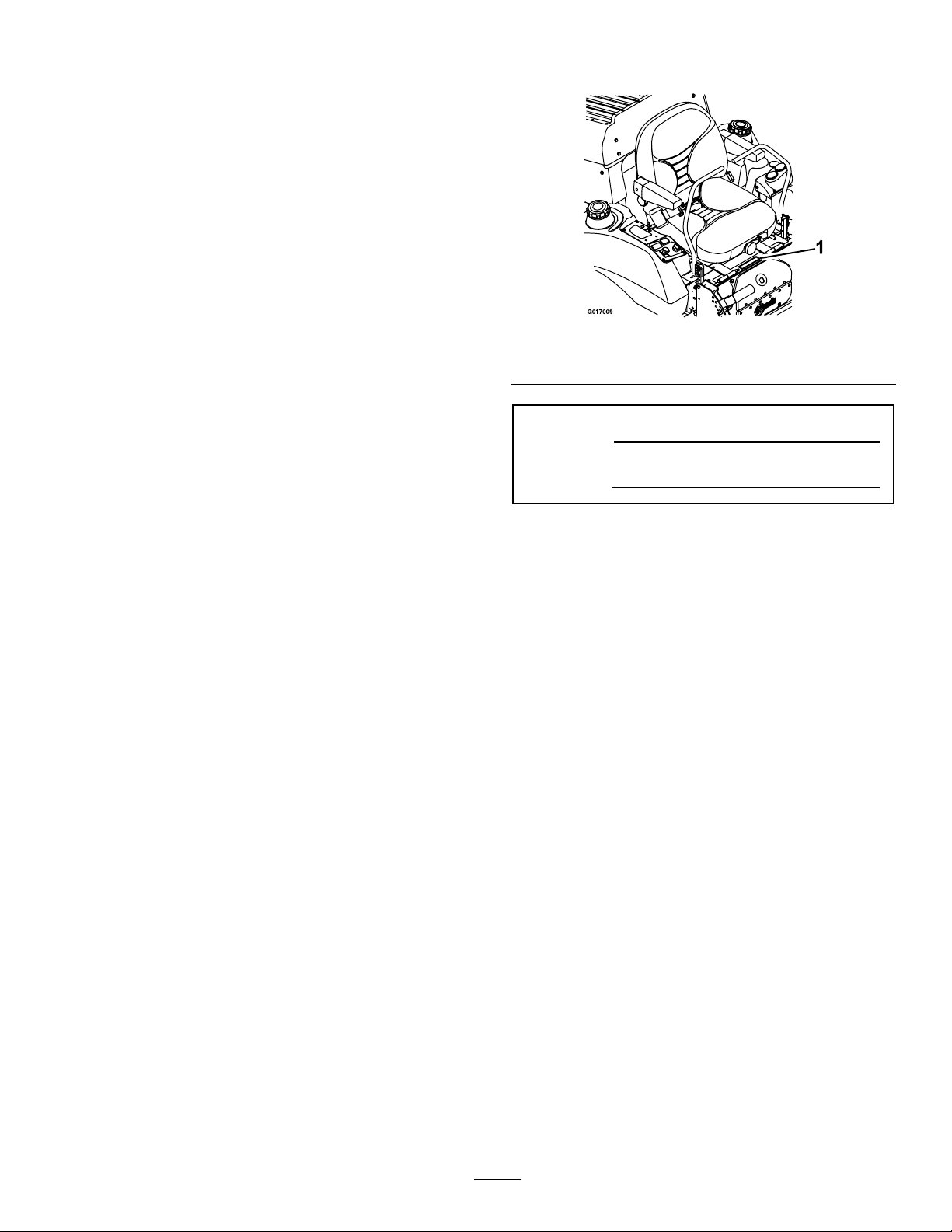
Figure1
1.Modelandserialnumberlocation
ModelNo.
SerialNo.
AllExmarkequipmentdealersanddistributorsare
keptinformedofthelatestmethodsofservicing
andareequippedtoprovidepromptandefcient
serviceintheeldorattheirservicestations.They
carryamplestockofservicepartsorcansecurethem
promptlyforyoufromthefactory.
AllExmarkpartsarethoroughlytestedandinspected
beforeleavingthefactory,however,attentionis
requiredonyourpartifyouaretoobtainthefullest
measureofsatisfactionandperformance.
Wheneveryouneedservice,genuineExmarkparts,
oradditionalinformation,contactanAuthorized
ServiceDealerorExmarkCustomerServiceandhave
themodelandserialnumbersofyourproductready.
Figure1identiesthelocationofthemodelandserial
numbersontheproduct.Writethenumbersinthe
spaceprovided.
3
Page 4

Contents
Introduction...........................................................3
Safety.....................................................................5
SafetyAlertSymbol.........................................5
SafeOperatingPractices..................................5
SafetyandInstructionalDecals......................11
Specications........................................................17
ModelNumbers.............................................17
Systems..........................................................17
Dimensions....................................................19
TorqueRequirements.....................................19
ProductOverview.................................................20
Operation..............................................................20
Controls.........................................................20
Pre-Start.........................................................22
OperatingInstructions...................................23
Transporting..................................................27
Maintenance..........................................................29
RecommendedMaintenanceSchedule(s)............29
PeriodicMaintenance........................................30
CheckEngineOilLevel..................................30
CheckBatteryCharge.....................................30
CheckMowerBlades......................................32
CheckSafetyInterlockSystem........................33
CheckRolloverProtectionsSystems(Roll
Bar)Pins....................................................33
CheckSeatBelt...............................................33
CheckforLooseHardware.............................33
ServiceAirCleaner.........................................33
ChangeEngineOil.........................................34
CheckHydraulicOilLevel..............................34
CheckTirePressures......................................34
CheckConditionOfBelts...............................35
LubricateGreaseFittings................................35
WheelHub-SlottedNutTorque
Specication...............................................36
LubricateBrakeHandlePivot.........................36
LubricateBrakeRodBushings........................36
LubricateMotionControlBronze
Bushings....................................................37
DrainFuelFilter/WaterSeparator...................37
ChangeFuelFilter/WaterSeparator................37
ChangeHydraulicSystemFilter......................37
CheckEngineCoolantLevel...........................38
ChangeEngineCoolant..................................38
CheckSparkArrester(ifequipped)..................39
ThreadLockingAdhesives..............................39
MobilHTSGrease(OrFood-Grade
Anti-seize)..................................................40
Copper-BasedAnti-seize...............................40
DielectricGrease............................................40
Adjustments......................................................40
DeckLeveling................................................40
PumpDriveBeltTension................................41
DeckBeltTension..........................................41
MuleDriveBeltTensionAdjustment..............41
AlternatorBeltTension..................................42
BeltGuideAdjustment...................................42
ParkingBrakeAdjustment..............................42
ElectricClutchAdjustment.............................44
ReverseIndicatorAdjustment.........................45
MotionControlLinkageAdjustment..............45
MotionControlDamperAdjustment..............47
CasterPivotBearingsPre-Load
Adjustment................................................47
Cleaning............................................................48
CleanEngineCoolingSystem.........................48
CleanEngineandExhaustSystem
Area...........................................................48
CleantheRadiator..........................................48
CleanDebrisFromMachine...........................49
CleanGrassBuild-UpUnderDeck.................49
WasteDisposal...............................................49
Troubleshooting....................................................50
Schematics............................................................53
4
Page 5

Safety
Safety
SafetyAlertSymbol
ThislawnmowermeetsorexceedstheB71.4
specicationsoftheAmericanNationalStandards
Instituteineffectatthetimeofproduction.
Exmarkdesignedandtestedthislawnmowertooffer
reasonablysafeservice;however,failuretocomply
withthefollowinginstructionsmayresultinpersonal
injury.
ThisSafetyAlertSymbol(
thismanualandonthemachinetoidentifyimportant
safetymessageswhichmustbefollowedtoavoid
accidents.
Thissymbolmeans:ATTENTION!BECOME
ALERT!YOURSAFETYISINVOLVED!
SafetyAlertSymbol
Figure2)isusedbothin
Figure2
SafeOperatingPractices
Training
•ReadtheOperator’ sManualandothertraining
material.Iftheoperator(s)ormechanic(s)can
notreadEnglishitistheowner’sresponsibilityto
explainthismaterialtothem.
•Becomefamiliarwiththesafeoperationofthe
equipment,operatorcontrols,andsafetysigns.
•Alloperatorsandmechanicsshouldbetrained.
Theownerisresponsiblefortrainingtheusers.
•Neverletchildrenoruntrainedpeopleoperate
orservicetheequipment.Localregulationsmay
restricttheageoftheoperator.
•Onlyadultsandmatureteenagersshouldoperate
amower,andevenmatureteenagersshouldhave
adultsupervision.Besureateenager:
1.hasreadandunderstandstheOperator's
Manualandrecognizestherisksinvolved;
2.issufcientlymaturetousecaution;and
3.isofsufcientsizeandweighttooperate
thecontrolscomfortablyandtomanagethe
mowerwithouttakingrisks.
Thesafetyalertsymbolappearsaboveinformation
whichalertsyoutounsafeactionsorsituations
andwillbefollowedbythewordDANGER,
WARNING,orCAUTION.
DANGER:Whitelettering/Redbackground.
Indicatesanimminentlyhazardoussituationwhich,if
notavoided,Willresultindeathorseriousinjury.
WARNING:Blacklettering/Orangebackground.
Indicatesapotentiallyhazardoussituationwhich,if
notavoided,Couldresultindeathorseriousinjury.
CAUTION:Blacklettering/Yellowbackground.
Indicatesapotentiallyhazardoussituationwhich,if
notavoided,Mayresultinminorormoderateinjury.
Thismanualusestwootherwordstohighlight
information.Importantcallsattentiontospecial
mechanicalinformationandNoteemphasizes
generalinformationworthyofspecialattention.
•Theowner/usercanpreventandisresponsible
foraccidentsorinjuriesoccurringtohimselfor
herself,otherpeopleorproperty.
Preparation
•Evaluatetheterraintodeterminewhataccessories
andattachmentsareneededtoproperlyand
safelyperformthejob.Onlyuseaccessoriesand
attachmentsapprovedbyExmark.
•Wearappropriateclothingincludingsafetyglasses,
substantialfootwear,longtrousers,andhearing
protection.DoNotoperatewhenbarefootor
whenwearingopensandals.Longhair,loose
clothingorjewelrymaygettangledinmoving
parts.
CAUTION
Thismachineproducessoundlevelsinexcess
of85dBAattheoperator’searandcancause
hearinglossthroughextendedperiodsof
exposure.
Wearhearingprotectionwhenoperatingthis
machine.
5
Page 6

Safety
•Inspecttheareawheretheequipmentistobe
usedandremoveallrocks,toys,sticks,wires,
bones,andotherforeignobjectswhichcanbe
thrownbythemachineandmaycausepersonal
injurytotheoperatororbystanders.
DANGER
Incertainconditionsdieselfuelisextremely
ammableandvaporsareexplosive.
Areorexplosionfromdieselfuelcanburn
you,others,andcausepropertydamage.
•Fillthefueltankoutdoorsonlevelground,
inanopenarea,whentheengineiscold.
Wipeupanydieselfuelthatspills.
•Neverrellthefueltankordrainthe
machineindoorsorinsideanenclosed
trailer.
•DoNotllthefueltankcompletelyfull.
Fillthefueltanktothebottomoftheller
neck.Theemptyspaceinthetankallows
dieselfueltoexpand.Overllingmay
resultinfuelleakageordamagetothe
engineoremissionsystem.
•Neversmokewhenhandlingdieselfuel,
andstayawayfromanopenameor
wheredieselfuelfumesmaybeignitedby
spark.
•Storedieselfuelinanapprovedcontainer
andkeepitoutofthereachofchildren.
•Addfuelbeforestartingtheengine.Never
removethecapofthefueltankoradd
fuelwhenengineisrunningorwhenthe
engineishot.
•Iffuelisspilled,DoNotattempttostart
theengine.Moveawayfromtheareaof
thespillandavoidcreatinganysourceof
ignitionuntilfuelvaporshavedissipated.
•DoNotoperatewithoutentireexhaust
systeminplaceandinproperworking
condition.
WARNING
Dieselfuelisharmfulorfatalifswallowed.
Long-termexposuretovaporshascaused
cancerinlaboratoryanimals.Failuretouse
cautionmaycauseseriousinjuryorillness.
•Avoidprolongedbreathingofvapors.
•Keepfaceawayfromnozzleandgas
tank/containeropening.
•Keepawayfromeyesandskin.
•Neversiphonbymouth.
•Checkthattheoperator'spresencecontrols,
safetyswitches,andshieldsareattachedand
functioningproperly .DoNotoperateunlessthey
arefunctioningproperly.
Operation
WARNING
Operatingengineparts,especiallythemufer,
becomeextremelyhot.Severeburnscanoccur
oncontactanddebris,suchasleaves,grass,
brush,etc.cancatchre.
•Allowengineparts,especiallythemufer,to
coolbeforetouching.
•Removeaccumulateddebrisfrommuferand
enginearea.
•Installandmaintaininworkingordera
sparkarresterbeforeusingequipment
onforest-covered,grass-covered,or
brush-coveredunimprovedland.
WARNING
Engineexhaustcontainscarbonmonoxide,
whichisanodorlessdeadlypoisonthatcankill
you.
DoNotrunengineindoorsorinasmallconned
areawheredangerouscarbonmonoxidefumes
cancollect.
•Operateonlyindaylightorgoodarticiallight,
keepingawayfromholesandhiddenhazards.
•Besurealldrivesareinneutralandparkingbrake
isengagedbeforestartingengine.Useseatbelts
withtherollbarintheraisedandlockedposition.
•Neveroperatethemowerwithdamagedguards,
shields,orcovers.Alwayshavesafetyshields,
6
Page 7

Safety
guards,switchesandotherdevicesinplaceandin
properworkingcondition.
•Nevermowwiththedischargedeectorraised,
removedoralteredunlessthereisagrass
collectionsystemormulchkitinplaceand
workingproperly.
•DoNotchangetheenginegovernorsettingor
overspeedtheengine.
•Parkmachineonlevelground.Stopengine,wait
forallmovingpartstostop,removekeyand
engageparkingbrake:
–Beforechecking,cleaningorworkingonthe
mower.
–Afterstrikingaforeignobjectorabnormal
vibrationoccurs(inspectthemowerfor
damageandmakerepairsbeforerestarting
andoperatingthemower).
–Beforeclearingblockages.
–Wheneveryouleavethemower.
•Stopengine,waitforallmovingpartstostop,and
engageparkingbrake:
–Beforerefueling.
–Beforedumpingthegrasscatcher.
WARNING
Hands,feet,hair,clothing,oraccessoriescan
becomeentangledinrotatingparts.Contact
withtherotatingpartscancausetraumatic
amputationorseverelacerations.
•DoNotoperatethemachinewithout
guards,shields,andsafetydevicesinplace
andworkingproperly.
•Keephands,feet,hair,jewelry,orclothing
awayfromrotatingparts.
•NEVERcarrypassengers.DONOToperate
themowerwhenpeople,especiallychildren,or
petsareinthearea.
•Beawareofthemowerdischargepathanddirect
dischargeawayfromothers.
•DoNotoperatethemowerundertheinuence
ofalcoholordrugs.
•Useextremecarewhenloadingorunloadingthe
machineintoatrailerortruck.
•Usecarewhenapproachingblindcorners,shrubs,
trees,orotherobjectsthatmayobscurevision.
SlopeOperation
UseExtremecautionwhenmowingand/orturning
onslopesaslossoftractionand/ortip-overcould
occur.Theoperatorisresponsibleforsafeoperation
onslopes.
DANGER
Operatingonwetgrassorsteepslopescancause
slidingandlossofcontrol.Wheelsdroppingover
edges,ditches,steepbanks,orwatercancause
rollovers,whichmayresultinseriousinjury,
deathordrowning.
•DoNotmowslopeswhengrassiswet.
•DoNotmowneardrop-offsornearwater.
•DoNotmowslopesgreaterthan15degrees.
•Reducespeedanduseextremecautionon
slopes.
•Avoidsuddenturnsorrapidspeedchanges.
•Keeptherollbarintheraisedandlocked
positionanduseseatbelt.
•Seeinsidethebackcovertodeterminethe
approximateslopeangleoftheareatobemowed.
•Useawalkbehindmowerand/orahandtrimmer
neardrop-offs,ditches,steepbanksorwater.
Figure3).
(
•Bealert,slowdownandusecautionwhen
makingturns.Lookbehindandtothesidebefore
changingdirections.
•Stoptheblades,slowdown,andusecaution
whencrossingsurfacesotherthangrassandwhen
transportingthemowertoandfromtheareato
bemowed.
7
Page 8
Safety
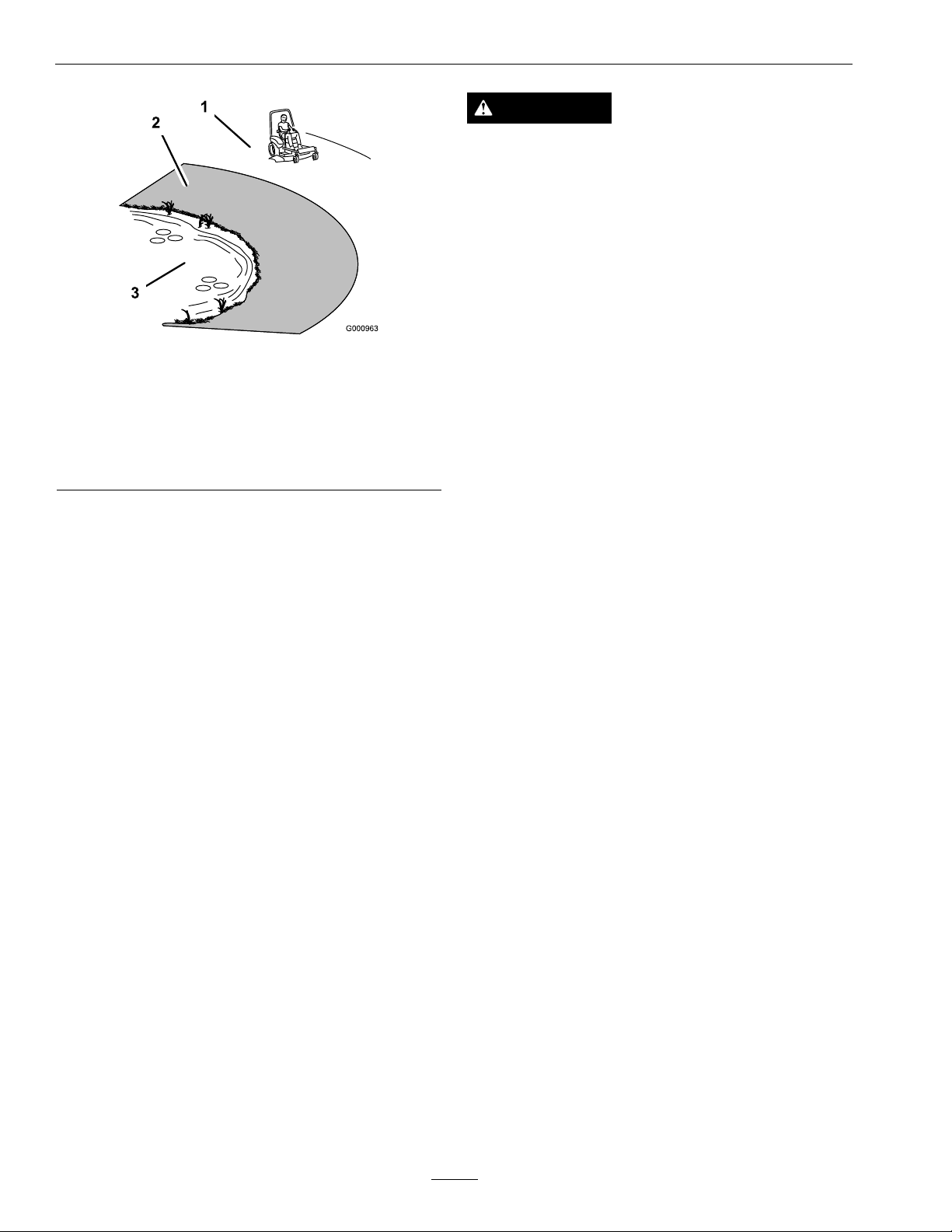
Figure3
1.SafeZone-Usethemowerhereonslopeslessthan15
degrees
2.DangerZone-Useawalkbehindmowerand/orhand
trimmeronslopesgreaterthan15degrees,near
drop-offsandwater.
3.Water
•Removeormarkobstaclessuchasrocks,tree
limbs,etc.fromthemowingarea.Tallgrasscan
hideobstacles.
•Watchforditches,holes,rocks,dipsandrisesthat
changetheoperatingangle,asroughterraincould
overturnthemachine.
•Avoidsuddenstartswhenmowinguphillbecause
themowermaytipbackwards.
•Beawarethatoperatingonwetgrass,acrosssteep
slopesordownhillmaycausethemowertolose
traction.Lossoftractiontothedrivewheelsmay
resultinslidingandalossofbrakingandsteering.
•Alwaysavoidsuddenstartingorstoppingona
slope.Iftireslosetraction,disengagetheblades
andproceedslowlyofftheslope.
•Followthemanufacturer’srecommendationsfor
wheelweightsorcounterweightstoimprove
stability.
•Useextremecarewithgrasscatchersor
attachments.Thesecanchangethestabilityofthe
machineandcauselossofcontrol.
WARNING
Thereisnorolloverprotectionwhentherollbar
isdown.Wheelsdroppingoveredges,ditches,
steepbanks,orwatercancauserollovers,which
mayresultinseriousinjury,deathordrowning.
•Keeptherollbarintheraisedandlocked
positionanduseseatbelt.
•Lowertherollbaronlywhenabsolutely
necessary.
•DoNotwearseatbeltwhentherollbaris
down.
•Driveslowlyandcarefully.
•Raisetherollbarassoonasclearance
permits.
•Checkcarefullyforoverheadclearances(i.e.
branches,doorways,andelectricalwires)before
drivingunderanyobjectsandDoNotcontact
them.
•Intheeventofarollover,taketheunittoan
AuthorizedServiceDealertohavetheROPS
inspected.
MaintenanceandStorage
•Disengagedrives,lowerimplement,setparking
brake,stopengineandremovekey.Waitforall
movementtostopbeforeadjusting,cleaningor
repairing.
•Keepengineandengineareafreefrom
accumulationofgrass,leaves,excessivegrease
oroil,andotherdebriswhichcanaccumulate
intheseareas.Thesematerialscanbecome
combustibleandmayresultinare.
•LetenginecoolbeforestoringandDoNotstore
nearameoranyenclosedareawhereopenpilot
lightsorheatappliancesarepresent.
•Shutofffuelwhilestoringortransporting.Do
Notstorefuelnearamesordrainindoors.
•Parkmachineonlevelground.Neverallow
untrainedpersonneltoservicemachine.
UsingtheRolloverProtectionSystem
(ROPS)
ARolloverProtectionSystem(rollbar)isinstalled
ontheunit.
•Usejackstandstosupportcomponentswhen
required.
•Carefullyreleasepressurefromcomponentswith
storedenergy.
•Disconnectbatterybeforemakinganyrepairs.
Disconnectthenegativeterminalrstandthe
8
Page 9

Safety
positivelast.Reconnectpositiverstandnegative
last.
•Usecarewhencheckingblades.Wraptheblade(s)
orweargloves,andusecautionwhenservicing
them.Onlyreplacedamagedblades.Never
straightenorweldthem.
•Keephandsandfeetawayfrommovingparts.
Ifpossible,DoNotmakeadjustmentswiththe
enginerunning.
•Chargebatteriesinanopenwellventilatedarea,
awayfromsparkandames.Unplugcharger
beforeconnectingordisconnectingfrombattery.
Wearprotectiveclothinganduseinsulatedtools.
DANGER
Chargingorjumpstartingthebatterymay
produceexplosivegases.Batterygasescan
explodecausingseriousinjury.
•Keepsparks,ames,orcigarettesaway
frombattery.
•Ventilatewhenchargingorusingbattery
inanenclosedspace.
•Makesureventingpathofbatteryis
alwaysopenoncebatteryislledwith
acid.
•Alwaysshieldeyesandfacefrombattery.
CAUTION
Iftheignitionisinthe“ON”positionthere
ispotentialforsparksandengagementof
components.Sparkscouldcauseanexplosion
ormovingpartscouldaccidentallyengage
causingpersonalinjury.
Besureignitionswitchisinthe“OFF”
positionbeforechargingthebattery.
•Keepallguards,shieldsandallsafetydevicesin
placeandinsafeworkingcondition.
•Checkallboltsfrequentlytomaintainproper
tightness.
•Frequentlycheckforwornordeteriorating
componentsthatcouldcreateahazard.
WARNING
Removingstandardoriginalequipmentparts
andaccessoriesmayalterthewarranty,traction,
andsafetyofthemachine.Failuretouseoriginal
Exmarkpartscouldcauseseriousinjuryor
death.Makingunauthorizedchangestothe
engine,fuelorventingsystem,mayviolateEPA
andCARBregulations.
Replaceallpartsincluding,butnotlimitedto,
tires,belts,blades,andfuelsystemcomponents
withoriginalExmarkparts.
DANGER
Batteryelectrolytecontainssulfuricacid,
whichispoisonousandcancausesevere
burns.Swallowingelectrolytecanbefatalor
ifittouchesskincancausesevereburns.
•Wearsafetyglassestoshieldeyes,and
rubberglovestoprotectskinandclothing
whenhandlingelectrolyte.
•DoNotswallowelectrolyte.
•Intheeventofanaccident,ushwith
waterandcalladoctorimmediately.
9
Page 10

Safety
WARNING
Hydraulicuidescapingunderpressure
canpenetrateskinandcauseinjury.Fluid
accidentallyinjectedintotheskinmustbe
surgicallyremovedwithinafewhoursbyadoctor
familiarwiththisformofinjuryorgangrenemay
result.
•Ifequipped,makesureallhydraulicuid
hosesandlinesareingoodconditionandall
hydraulicconnectionsandttingsaretight
beforeapplyingpressuretohydraulicsystem.
•Keepbodyandhandsawayfrompinhole
leaksornozzlesthatejecthighpressure
hydraulicuid.
•Usecardboardorpaper,notyourhands,to
ndhydraulicleaks.
•Safelyrelieveallpressureinthehydraulic
systembyplacingthemotioncontrollevers
inneutralandshuttingofftheenginebefore
performinganyworkonthehydraulicsystem.
WARNING
Fuelsystemcomponentsareunderhigh
pressure.Theuseofimpropercomponentscan
resultinsystemfailure,fuelleakageandpossible
explosion.
Useonlyapprovedfuellinesandfuelltersfor
highpressuresystems.
10
Page 11
SafetyandInstructionalDecals
Safety
•Keepallsafetysignslegible.Removeallgrease,
dirtanddebrisfromsafetysignsandinstructional
labels.
•Replaceallworn,damaged,ormissingsafety
signs.
•Whenreplacementcomponentsareinstalled,be
surethatcurrentsafetysignsareafxedtothe
replacedcomponents.
•Ifanattachmentoraccessoryhasbeeninstalled,
makesurecurrentsafetysignsarevisible.
1-303508
•Newsafetysignsmaybeobtainedfrom
yourauthorizedExmarkequipmentdealeror
distributororfromExmarkMfg.Co.Inc.
•Safetysignsmaybeafxedbypeelingoffthe
backingtoexposetheadhesivesurface.Apply
onlytoaclean,drysurface.Smoothtoremove
anyairbubbles.
•Familiarizeyourselfwiththefollowingsafetysigns
andinstructionlabels.Theyarecriticaltothesafe
operationofyourExmarkcommercialmower.
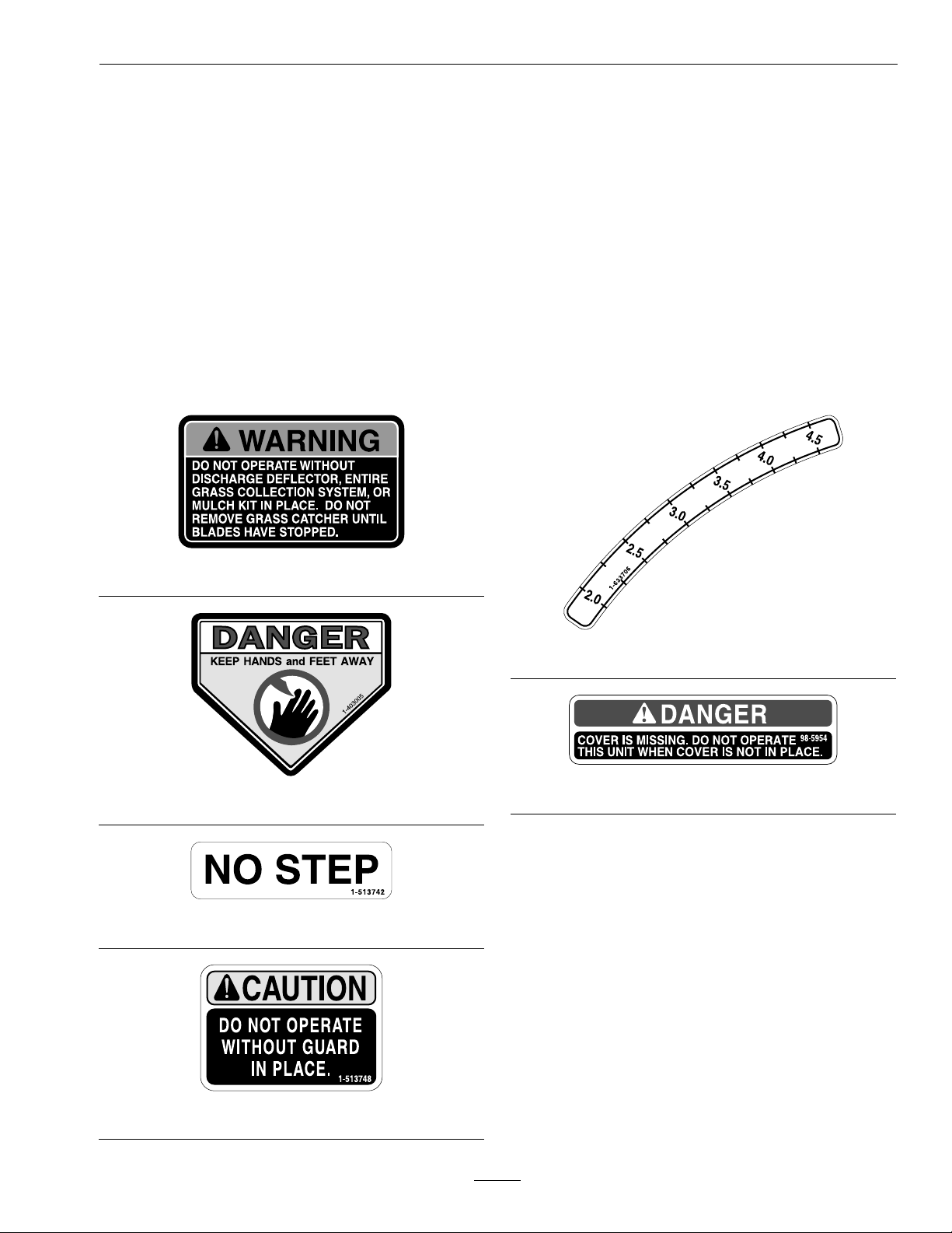
1-633706
1-403005
1-513742
98-5954
1-513748
11
Page 12
Safety
103-2076
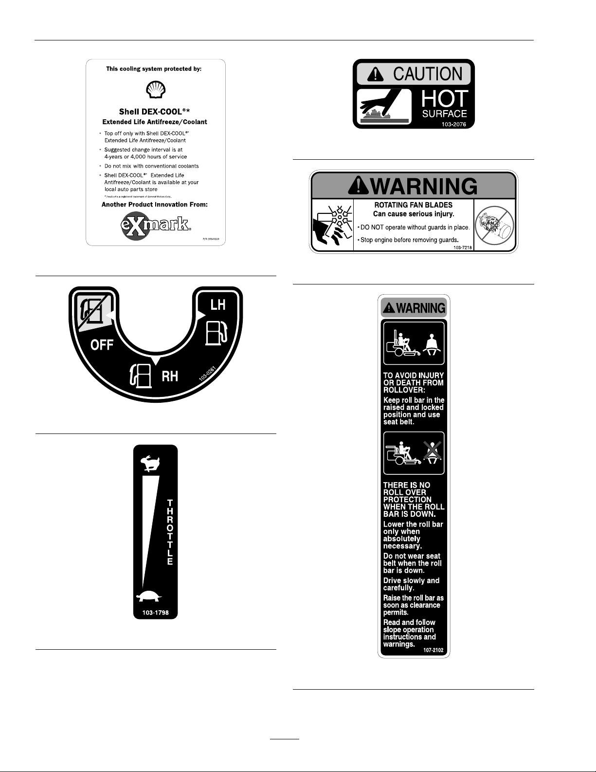
103-0223
103-0261
103-7218
103-1798
107-2102
12
Page 13
Safety
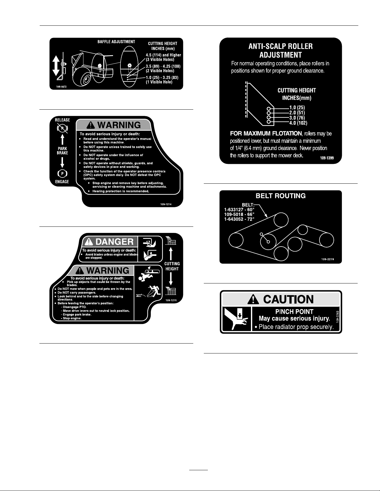
109-0872
109-1399
109-1214
109-2219
109-1215
109-2263
13
Page 14
Safety
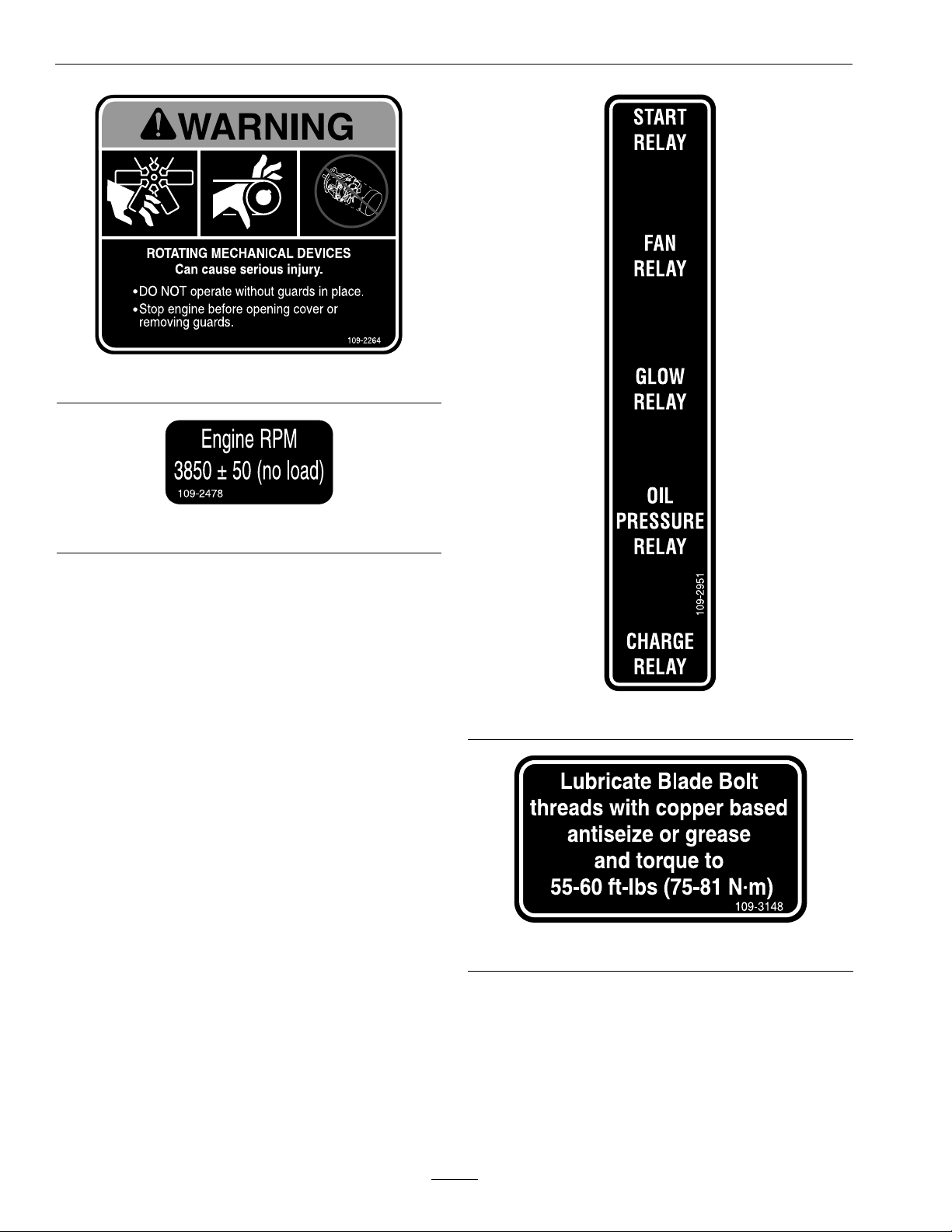
109-2264
109-2478
109-2951
109-3148
14
Page 15
Safety
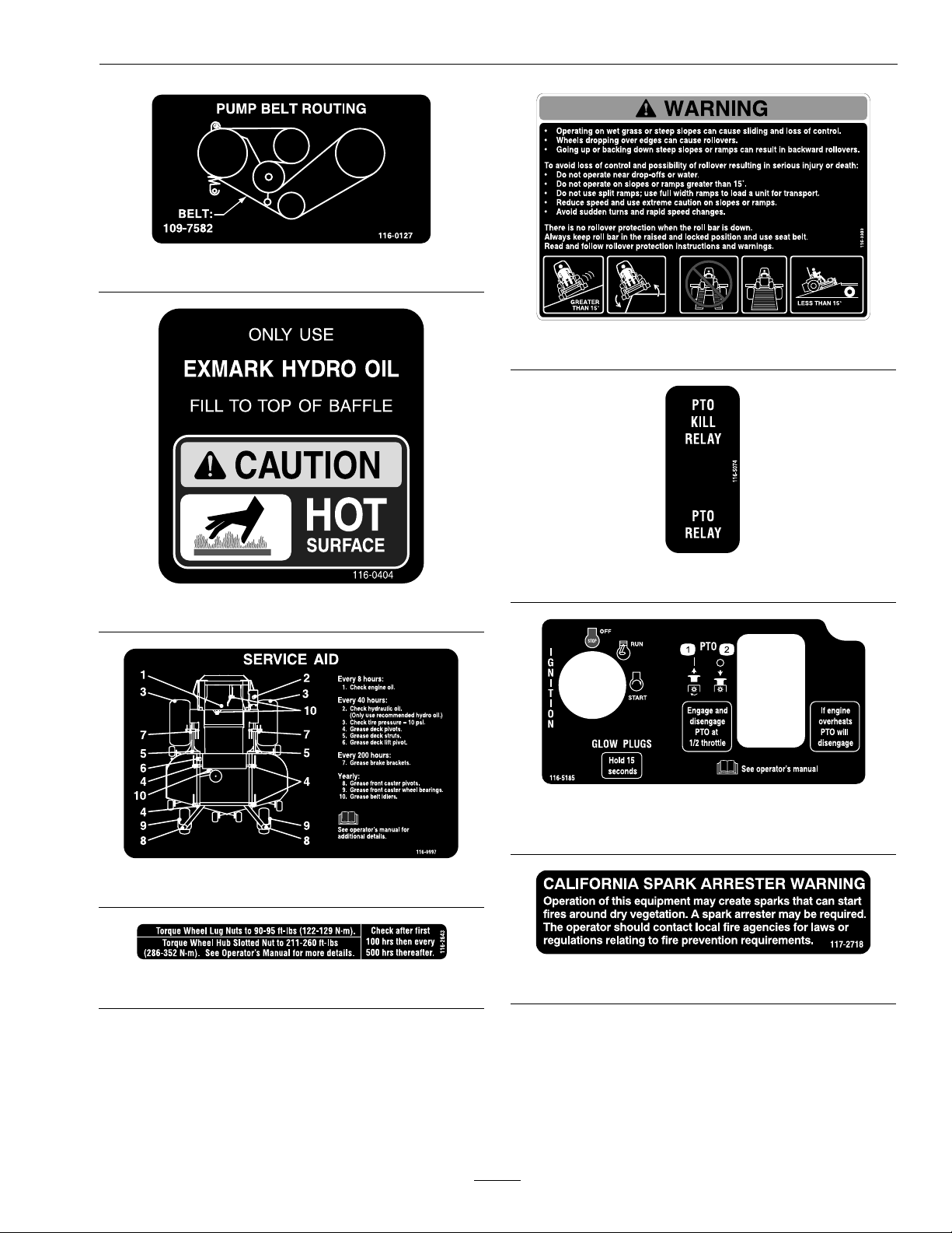
116-0127
116-3303
116-5074
116-0404
116-5185
1.PTO–engage2.PTO–disengage
116-0997
116-2643
117–2718
15
Page 16
Safety
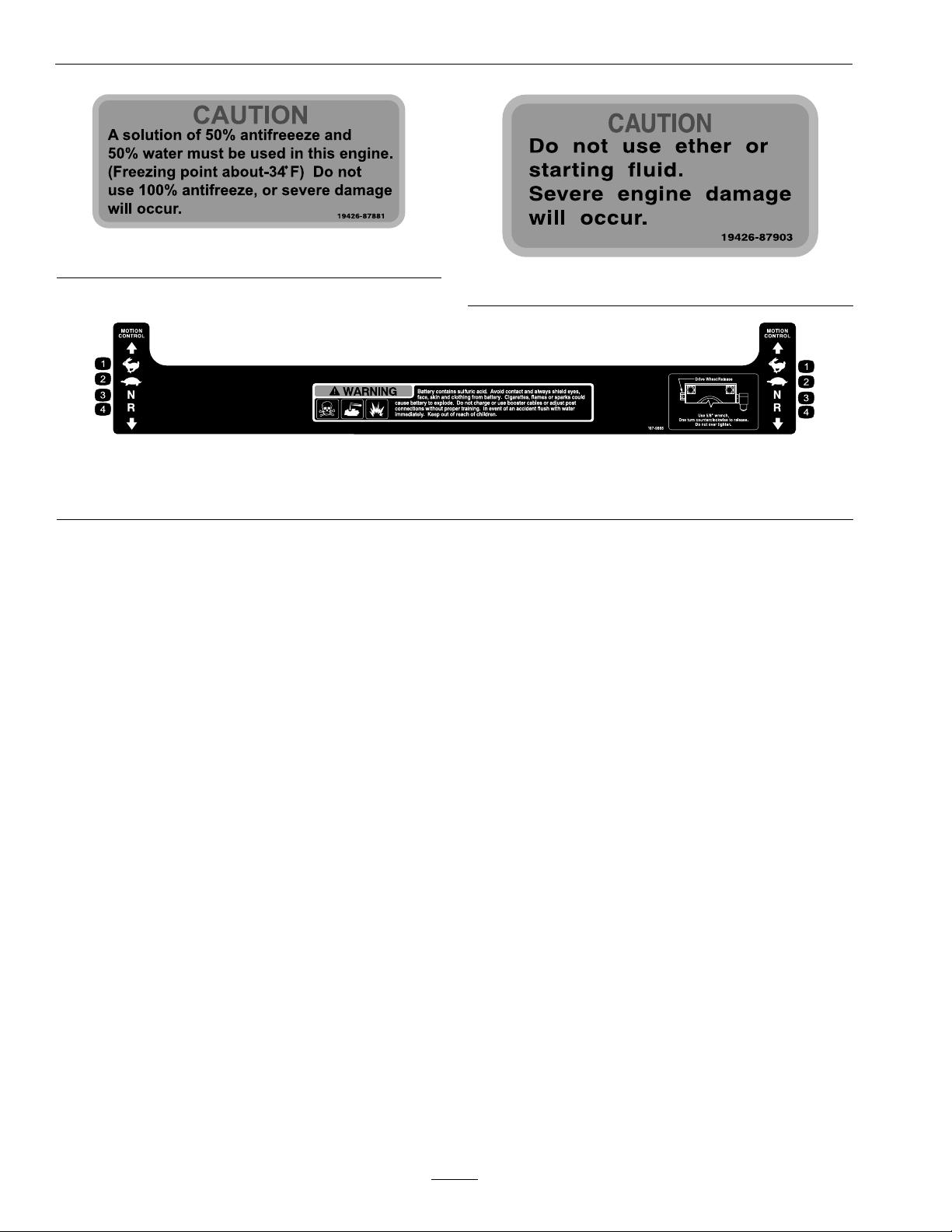
19426-87881
1.Fast3.Neutral
2.Slow
19426-87903
107-9866
4.Reverse
16
Page 17

Specications
ModelNumbers
SerialNos:312,000,000andHigher
LZDS902K605;LZDS902K725
Specications
Systems
Engine
•EngineSpecications:SeeyourEngineOwner’ s
Manual
•EngineOilType:Exmark4–CyclePremium
EngineOil
•RPM:FullSpeed:3850±50RPM(PTOnot
engaged)Idle:1400±100RPM
FuelSystem
•Capacity:15.5gal.(58.6L)
•TypeofFuel:Dieselfuel,40cetaneorhigheror
biodieseluptoB20(20%biodiesel,80%petro
diesel).
•FuelFilter:In-line113Micron
ExmarkP/N112-7836.
•FuelShut-OffValve:1/4turnincrements
(“OFF”,righttank,lefttank,)
•Fuelgaugeinlefthandfueltank.
•OperatormustbeinseatwhenPTOisengaged,
brakeisdisengaged,ormotioncontrolleversare
movedinorenginewillstop.
•Enginewillstopifeithertheleft,theright,or
bothleversaremovedfromneutrallockposition
whilebrakeisengaged.
EngineOverheatProtectionSystem
PTOwilldisengage,analarmwillsound,andthe
coolanttemperaturegaugewillbeintheredarea
whentheenginetemperaturereachesanoverheat
condition.ThePTOwillnotre-engageuntilthe
enginehascooledandthePTOswitchismanually
shut-offandre-engaged.
Note:Iftheenginecoolantlevelisbelowthe
indicatorlineontheoverowbottlewhenthe
engineiscold,thecoolanttemperaturegaugemay
notregistercorrectlyduringoperationand/or
thewarningbuzzermaynotsoundiftheengine
overheats.RefertoCheckEngineCoolantLevel
inMaintenance.
ElectricalSystem
•ChargingSystem:ExternalAlternator
•ChargingCapacity:60amps
•BatteryType:BCIGroup26
•RecommendedMinimumBatteryCCA:540CCA
•BatteryVoltage:12Volt
•Polarity:NegativeGround
•Fuses:One20ampbladetype;One30ampblade
type
SafetyInterlockSystem
•PTOmustbedisengaged,brakeengaged,and
motioncontrolleversout(neutrallock)tostart
engine.(Itisnotnecessaryfortheoperatortobe
intheseattostarttheengine.)
CoolingSystem
•Fan:Electricwithcontinuousoperationwith
enginerunning.
•CoolantLiquid:50/50mixofDexCool©
extendedlifeantifreezeandwater.
•CoolantCapacity:4quarts
OperatorControls
•SteeringandMotionControl:
Note:Motioncontrolleversareadjustableto
twoheights.
–Separatelevers,oneachsideoftheconsole,
controlspeedanddirectionoftravelofthe
respectivedrivewheels.
–Steeringiscontrolledbyvaryingtheposition
oftheleversrelativetoeachother.
17
Page 18

Specications
–Movingmotioncontrolleversoutward(in
slots)locksthedrivesysteminneutral.
•PTOEngagementSwitch:Engageselectricclutch
(todrivebelt)whichengagesmowerblades.
•ParkingBrakeLever:Engagesparkingbrake.
•DeckHeightAdjustmentLever:Setscutting
heighttodesiredposition.
•DeckLiftAssistPedal:Footpedalthatassistsin
raisingthedeck.
Seat
•Type:Deluxesuspensionseathighback,low
prolefoam-in-placecushion(dampened,
adjustablespringsuspension)andarmrests,
adjustablebackangle.
•Mounting:Hingedtotiltupforaccessto
hydraulicpumps,batteryandothercomponents.
Heldintiltedpositionwithscissor—typelinks.
Adjustableforeandaftseattrack.
•Armrests:Moldedadjustableip-uparmrests.
•SeatSafetySwitch:Integratedseatswitch.
Timedelayseatswitcheliminatesroughground
cut-outs.
HydrostaticGroundDriveSystem
•HydrostaticPumps:TwoHydroGearPW
variabledisplacementpistonpumps.
•WheelMotors:TwoParker/Rosswith11/4inch
taperedshafts.
•HydraulicOilType:ExmarkPremiumHydrooil.
•HydraulicOilCapacity:5.5qt.(5.2L)
•HydraulicFilter:Replaceablecartridgetype.
P/N103-2146:25microns,Nobypass
•Speeds:
–0-12.0mph(19.3km/hr)forward.
DriveFrontCaster
TreadSize
Size26x12.00-1213x6.50-6
PlyRating
Pressure
“Multi-TracC/S”
4
10psi(69kPa)
Smooth
CuttingDeck
•CuttingWidth:
–60inch(152.4cm)
–72inch(182.9cm)
•Discharge:Side
•BladeSize:(3ea.)
–60inchDeck:20.75inches(52.7cm)
–72inchDeck:24.75inches(62.9cm)
•BladeSpindles:Solidsteelspindleswith1.18inch
(30mm)I.D.bearings.
•DeckDrive:
–Electricclutchmountedonhorizontalengine
shaft.“B”Sectionbelt(withself-tensioning
idler)fromelectricclutchtotransfershaft
mountedondeck.
–Bladesaredrivenbyone“B”Sectionbelt
(w/self-tensioningidler)fromtransfershaft
ondecktobladespindles.
•Deck:
Fulloatingdeckisattachedtoout-frontsupport
frame.Sixanti-scalprollersprovidemaximum
turfprotection.Deckdesignallowsforbagging,
mulchingorsidedischarge.
•DeckDepth:
–60inchDeck:6.0inches(15.2cm)
–72inchDeck:6.0inches(15.2cm)
–0-8.0mph(12.9km/hr)reverse.
•Drivewheelreleasevalvesallowmachinetobe
movedwhenengineisnotrunning.
Tires&Wheels
DriveFrontCaster
Pneumatic
(Air-Filled)
Quantity
22
Semi-Pneumatic
•CuttingHeightAdjustment:
Anextra-longcushionedleverisusedtoadjust
thecuttingheightfrom1inch(2.5cm)to5inches
(12.7cm)in1/4inch(6.4mm)increments.The
cuttingheightadjustmenthandlehasatransport
positionandalladjustmentscanbemadewhile
theoperatorremainsseated.Unitsalsohavea
footoperateddeckliftassistlevertoaidinraising
thedeck.
•MulchingKit:Optional.
18
Page 19

Specications
Dimensions
OverallWidth:
60inchDeck72inchDeck
WithoutDeck53.5inches(135.9
cm)
DeectorUp61.4inches(156.0
cm)
DeectorDown72.8inches(184.9
cm)
OverallLength:
60inchDeck72inchDeck
RollBar-Up81.9inches(208.0
cm)
RollBar-Down92.5inches(235.0
cm)
OverallHeight:
RollBar-UpRollBar-Down
72.7inches(184.7cm)53.8inches(136.7cm)
61.5inches(156.2
cm)
74.3inches(188.7
cm)
85.8inches(217.9
cm)
85.8inches(217.9
cm)
96.4inches(244.9
cm)
TorqueRequirements
BoltLocation
BladeDriveSheave
MountingNut
CutterHousingSpindle
Nut
BladeMountingBolt
(lubricatewithanti-seize)
EngineDeck/FrontFrame
MountBolts
Anti-ScalpRollerNyloc
NutSeeFigure12
Anti-ScalpRollerHex
CapscrewSeeFigure12
EngineMountingBolts
1/2-13inchscrews
M10screws
WheelLugNuts
WheelMotorMounting
Bolts
WheelHubSlottedNut211-260ft-lb
RolloverProtectionSystem
(RollBar)MountingBolts
Torque
90-110ft-lb(122-149N-m)
160-185ft-lb(217-251
N-m)
55-60ft-lb(75-81N-m)
30-35ft-lb(41-47N-m)
30-35ft-lb(41-47N-m)
50-55ft-lb(68-75N-m)
67-83ft-lb(99-113N-m)
30ft-lb(41N-m)
90-95ft-lb(122-129N-m)
72-77ft-lb(98-104N-m)
(286-352N-m)
30-35ft-lb(41-47N-m)
TreadWidth:(CentertoCenterof
Tires,Widthwise)
60inchDeck72inchDeck
DriveWheels41.9inches(106.4
cm)
CasterWheels37.3inches(94.7
cm)
45.9inches(116.6
cm)
47.3inches(120.1
cm)
WheelBase:(CenterofCasterTireto
CenterofDriveTire)
60inchDeck72inchDeck
56.0inches(142.2cm)60.2inches(152.9cm)
CurbWeight:
60inchDeck72inchDeck
1545lb(701kg)1645lb(746kg)
DeckDriveJackshaftNut
ClutchRetainingBolt
(securedwiththreadlocker)
ExhaustMuferNutsand
MountingBolts
75-80ft-lb(102-108N-m)
55-60ft-lb(75-81N-m)
228in-lb(26N-m)
19
Page 20

Operation
ProductOverview
Operation
Note:Determinetheleftandrightsidesofthe
machinefromthenormaloperatingposition.
Controls
MotionControlLevers
Themotioncontrolleverslocatedoneachsideof
theconsolecontroltheforwardandreversemotion
ofthemachine.
Movingtheleversforwardorbackwardturns
thewheelonthesamesideforwardorreverse
respectively.Wheelspeedisproportionaltothe
amounttheleverismoved.
Movingtheleversoutwardfromthecenterposition
intotheT-slotlocksthemintheneutralposition
Figure5).
(
Figure4
1.Motioncontrollevers
2.Parkingbrake
3.Heightofcutadjustment
4.Fuelcap(bothsides)
5.EngineControls(right
console)
6.Seatbelt
7.RolloverProtection
System(ROPS)
1.Neutrallockposition
(handlesout)
2.Neutraloperateposition
(handlesin)
3.FrontofUnit
4.Forward
Figure5
5.Neutral(operate)
6.Reverse
7.Neutrallock
ThrottleControl
Locatedonrightfueltank.
Thethrottleisusedtocontrolenginespeed.Moving
thethrottleleverforwardwillincreaseenginespeed
20
Page 21

Operation
andmovingthethrottlelevertotherearwilldecrease
enginespeed.Movingthethrottleforwardintothe
detentisfullthrottle.
BrakeLever
Locatedonleftsideofunit,justtothefrontofthe
console.
Thebrakeleverengagesaparkingbrakeonthedrive
wheels.
Pulltheleverupandrearwardtoengagethebrake.
Pushtheleverforwardanddowntodisengagethe
brake.
Theunitmustbetieddownandbrakeengagedwhen
transporting.
IgnitionSwitch
Locatedonrightfueltank.
Theignitionswitchisusedtostartandstopthe
engine.Theswitchhasthreepositions“OFF”,“ON”
and“START”.Insertkeyintoswitchandrotate
clockwisetothe“ON”position.Rotateclockwiseto
thenextpositiontoengagethestarter(keymustbe
heldagainstspringpressureinthisposition).
Note:Brakemustbeengaged,motioncontrollevers
out(neutrallockposition)andPTOswitch“OFF”to
startengine.(Itisnotnecessaryfortheoperatorto
beintheseattostarttheengine.)
Thevalvehasthreepositions,eachpositionmade
in1/4turnincrements.
FuelFlowValveHandlePosition
“Off”Right
RightTank
LeftTankLeft
Down
FuelGauge
Locatedontheleftfueltank.
Thefuelgaugemonitorstheamountoffuelintheleft
tankonly.Usethefuelfromtherightfueltankrst.
Whentherightfueltankisempty,switchtotheleft
fueltank.Fuelgaugewillmonitortheremainingfuel.
DriveWheelReleaseValves
Locatedonthetoprightfrontcornerofhydrostatic
pumps.
Drivewheelreleasevalvesareusedtoreleasethe
hydrostaticdrivesystemtoallowthemachinetobe
pushedwithouttheenginerunning.Unhookseat
latchandtiltseatuptogainaccesstopumps.
Witha5/8inchwrench,turnbothvalvesoneturn
counterclockwisetoreleasedrivesystem.Turn
clockwisetoresetsystem.DoNotovertighten.Do
Nottowmachine.
TrackingAdjustmentKnob
HourMeter
Locatedontherightfueltank.
Thehourmeterisconnectedtoapressureswitch
installedintheengineblockanditrecordsthe
numberofhoursthattheenginehasrun.Ifthe
ignitionswitchisleftonwithoutenginerunning,
hourmeterwillnotrun.
Note:Thisswitchisnotalowoilsensorandwillnot
alerttheoperatoriftheengineoilislow.
FuelShut-OffValve
Locateddirectlybelowtherightsideofconsole,next
tothecubby.
Thefuelshut-offvalveisusedtoshutoffthefuel
whenthemachinewillnotbeusedforafewdays,
duringtransporttoandfromthejobsite,andwhen
parkedinsideabuilding.
LocatedundertheseatontheLHpumpcontrollink.
Rotatingthisknoballowsnetuningadjustmentsso
thatthemachinetracksstraightwiththedrivelevers
inthefullforwardposition.
Stopmachineandwaitforallmovingpartstostop.
Engageparkbrake.Unhookseatlatchandtiltseat
forwardtogainaccesstothetrackingknob.Rotate
theknobclockwise(asviewedfromtherearofthe
machine)tocausethemachinetotrackmoretothe
rightandcounterclockwisetocausethemachine
totrackmoretotheleft.Adjustinquarter-turn
incrementsuntilthemachinetracksstraight.Check
thatthemachinedoesnotcreepwheninneutralwith
theparkbrakedisengaged.
Important:DoNotrotatetheknobtoofar,as
thismaycausethemachinetocreepinneutral.
RefertotheMotionControlLinkageAdjustment
sectioninMaintenance.
21
Page 22

Operation
PTOEngagementSwitch
Locatedonrightfueltank.
Switchmustbepulledout(up)toengagetheblades.
Switchispushedintodisengagetheblades.
Note:Iftheengineoverheats,thePTOwill
automaticallydisengage.ThePTOcannotbeengaged
untiltheenginehascooleddown.Tore-engagethe
PTO,pushPTOswitchintothedisengagedposition
andthenpullouttoengage.RefertotheEngine
overheatsintheTroubleshootingsection.
CoolantTemperatureGauge
Locatedatthefrontoftheleftfueltank.
Thecoolanttemperaturegaugemonitorsthe
temperatureoftheenginecoolant.Anengine
overheatingconditionisindicatedbytheredarea
onthegauge.AnalarmwillsoundandthePTO
willdisengage.RefertotheWarningBuzzerinthe
Troubleshootingsection.
WarningBuzzer
Locatedbehindtheseatundertheairdeectoron
theelectricalpanel.
Thebuzzerisawarningsignalthattheengine
isoverheatingortheoilpressureislow .Seethe
Troubleshootingsection.
Note:Iftheenginecoolantlevelisbelowthe
indicatorlineontheoverowbottlewhentheengine
iscold,thewarningbuzzermaynotsoundifthe
engineoverheats.RefertoCheckEngineCoolant
LevelinMaintenance.
DeckLiftPedal
Locatedattherightfrontcorneroftheoorpan.
Pushthepedalforwardwithyourfoottoraisethe
cuttingdeck.Allowthepedaltomoverearwardto
lowerthecuttingdecktothecutheightthathasbeen
set.
Note:Iftheenginecoolantlevelisbelowthe
indicatorlineontheoverowbottlewhentheengine
iscold,thecoolanttemperaturegaugemaynot
registercorrectlyduringoperation.RefertoCheck
EngineCoolantLevelinMaintenance.
Voltmeter
LocatednexttotheCoolantTemperatureGaugeat
thefrontoftheleftfueltank.
Thevoltmetermeasurethevoltageoutputofthe
alternator.Bothhighandlowvoltageswillpotentially
damagethebattery.
GlowPlugSwitchandLight
Locatedontherightfueltank.
Depressandholdtheswitchtoheattheglowplugs.
Theglowpluglightcomesonwhentheglowplug
switchisdepressed.Theglowpluglightindicatesthe
glowplugsarepreheatingthecombustionchamber.
LowOilPressureLight
Locatedontherightfueltank.
Lightwillcomeonwhenengineoilpressureislow
orlost.
Pre-Start
Fillfueltankonlevelground.
Makesureyouunderstandthecontrols,their
locations,theirfunctions,andtheirsafety
requirements.
RefertotheMaintenancesectionandperformallthe
necessaryinspectionandmaintenancesteps.
DeterminingFuel
Theenginerunsonclean,freshdieselfuelwith
aminimumoctaneratingof40.Purchasefuelin
quantitiesthatcanbeusedwithin30daystoensure
fuelfreshness.
Usesummergradedieselfuel(No.2-D)at
temperaturesabove20°F(-7°C)andwintergrade
dieselfuel(No.1-DorNo.1-D/2-Dblend)below
20°F(-7°C).Useofwintergradedieselfuelatlower
temperaturesprovideslowerashpointandpour
pointcharacteristics,thereforeeasingstartabilityand
lesseningchancesofchemicalseparationofthefuel
duetolowertemperatures(waxappearance,which
maypluglters).
Useofsummergradedieselfuelabove20°F(-7°C)
willcontributetowardlongerlifeofthepump
components.
22
Page 23

Operation
Important:DoNotusekeroseneorgasoline
insteadofdieselfuel.Failuretoobservethis
cautionwilldamagetheengine.
DoNotoverllfueltank.Fillthefueltanktothe
bottomofthellerneck.Theemptyspaceinthe
tankallowsthefueltoexpand.Overllingmayresult
infuelleakageordamagetotheengineoremission
system.
Ifpossible,llthefueltankaftereachuse.Thiswill
minimizepossiblebuildupofcondensationinsidethe
fueltank.
BiodieselReady
Thismachinecanalsouseabiodieselblendedfuel
ofuptoB20(20%biodiesel,80%petrodiesel).The
petrodieselportionshouldbeloworultralowsulfur.
Observethefollowingprecautions:
•Thebiodieselportionofthefuelmeets
specicationASTMD6751orEN14214.
•Theblendedfuelcompositionshouldmeet
ASTMD975orEN590.
•Paintedsurfacesmaybedamagedbybiodiesel
blends.
•UseB5(biodieselcontentof5%)orlesserblend
incoldweather.
•Monitorseals,hoses,gasketsincontactwithfuel
astheymaydegradeovertime.
•Fuellterpluggingmaybeexpectedforatime
afterconvertingtobiodieselblends.
•Contactyourdistributorifyouwishformore
informationonbiodiesel.
rearpartoftheseatissecuredwiththeseat
latch.
Figure6
1.Rollbar3.Pin
2.Raisedposition4.Hairpincotterpin
OpentheFuelShut-OffValve
TurnthevalvetotheLHorRHtank.
StartingtheEngine
1.Movethemotioncontrolleversouttotheneutral
lockposition.
OperatingInstructions
RaisetheRolloverProtectionSystem
(ROPS)
Important:Lowertherollbaronlywhen
absolutelynecessary.
1.Removethehairpincotterpinsandremovethe
tworollbarpins(
2.Raisetherollbartotheuprightpositionand
installthetwopinsandsecurethemwiththe
hairpincotterpins(Figure6).
Important:Alwaysusetheseatbeltwiththe
rollbarintheraisedposition.Ensurethatthe
Figure6).
2.Pullupandbackontheparkingbrakeleverto
engagetheparkingbrake.
3.PushdownonthePTOswitchtothe“disengage”
position.
Note:Itisnotnecessaryfortheoperatortobe
intheseattostarttheengine.
4.Placethethrottlemidwaybetweenthe“SLOW”
and“FAST”positions.
5.Onawarmengine,placethethrottleinthe
“SLOW”position.
6.Onacoldengine,(below14°F(-10°C)),placethe
throttleinthe“MIDWAY”position.
Note:DoNotusefuelleftoverfromsummer.
23
Page 24

Operation
7.Turnignitionswitchtothe“ON”position.
Depresstheglowplugswitchandtheglowplug
lightwillturnon.Holdswitchasrequiredby
chartbelow.Turntheignitionswitchtothe
“START”position.Releasetheignitionswitchas
soonastheenginestarts.
GlowPlugChart
AmbientTemperature
Above50°F(10°C)
50°F(10°C)to23°F(-5°C)
Below23°F(-5°C)
Limitofcontinuoususe
HoldGlowPlugsOn
NONEED
Approximately5seconds
Approximately10seconds
20seconds
Theglowpluglight,locatedneartheglow
plugswitch,willilluminatewhentheswitchis
depressed.Theglowpluglightindicatestheglow
plugsarepreheatingthecombustionchamber.
Important:DoNotcranktheengine
continuouslyformorethentensecondsata
time.Iftheenginedoesnotstart,allowa30
secondcool-downperiodbetweenstarting
attempts.Failuretofollowtheseguidelines
canburnoutthestartermotorand/orfuel
solenoid.
8.Movethethrottletothe“SLOW”(ifin
“MIDWAY”)andlettheenginewarmupafew
minutesbeforemovingthethrottletothe“FAST”
position.
DANGER
Anuncovereddischargeopeningwillallow
objectstobethrowninanoperator’sor
bystander’sdirection.Also,contactwiththe
bladecouldoccur.Thrownobjectsorblade
contactcancauseseriousinjuryordeath.
Neveroperatethemowerwiththedischarge
deectorraised,removed,oralteredunlessthere
isagrasscollectionsystemormulchkitinplace
andworkingproperly.
ThePTOpush-pullswitchengagesthecuttingblades.
Besurethatallpersonsareclearofthemowerdeck
anddischargeareabeforeengagingPTO.
Important:Operatormustbeinseatbeforethe
PTOcanbeengaged.
1.Setthethrottlemidwaybetweenthe“SLOW”and
“FAST”positions.
2.PullthePTOswitchoutwardtoengagetheblades.
3.Placethethrottleinthe“FAST”positiontobegin
mowing.
DisengagingthePTO
1.Setthethrottlemidwaybetweenthe“SLOW”and
“FAST”positions.
2.PushthePTOswitchintodisengagetheblades.
StoppingtheEngine
EngagingthePTO
DANGER
Therotatingbladesunderthemowerdeckare
dangerous.Bladecontactcancauseserious
injuryorkillyou.
DoNotputhandsorfeetunderthemoweror
mowerdeckwhenthebladesareengaged.
1.Bringtheunittoafullstop.
2.Movethemotioncontrolleversouttotheneutral
lockposition.
3.Engagetheparkingbrake.
4.Placethethrottlemidwaybetweenthe“SLOW”
and“FAST”positions.
5.DisengagethePTO.
6.Allowtheenginetorunforaminimumof15
seconds,thenturntheignitionswitchtothe
“OFF”positiontostoptheengine.
7.Removethekeytopreventchildrenorother
unauthorizedpersonsfromstartingengine.
8.Closethefuelshut-offvalvewhenthemachine
willnotbeinuseforafewdays,when
transporting,orwhentheunitisparkedinside
abuilding.
24
Page 25

Operation
DrivingtheMachine
CAUTION
Machinecanspinveryrapidlybypositioningone
levertoomuchaheadoftheother.Operatormay
losecontrolofthemachine,whichmaycause
damagetothemachineorinjury.
•Usecautionwhenmakingturns.
•Slowthemachinedownbeforemakingsharp
turns.
Important:Tobeginmovement(forwardor
backward)theoperatormustbeintheseat,the
brakelevermustbedisengaged(pusheddown)
beforethemotioncontrolleverscanbemovedin
ortheenginewillstop.
Whenthemotioncontrolleversarepositionedfully
outward(apart)intheT-slot,thedrivesystemisin
theneutrallockposition(
Whenthemotioncontrolleversaremoveddirectly
inward(together)thedrivesystemisintheneutral
operateposition.
Figure7).
3.Tomoveforwardinastraightline,moveboth
leversforwardwithequalpressure.
Figure8
Toturnleftorright,pullthemotioncontrollever
backtowardneutralinthedesiredturndirection.
Themachinewillmovefasterthefartherthe
motioncontrolleversaremovedfromtheneutral
position.
Figure7
1.Neutrallockposition
(handlesout)
2.Neutraloperateposition
(handlesin)
3.FrontofUnit
4.Forward
5.Neutral(operate)
6.Reverse
7.Neutrallock
DrivingForward
1.Releasetheparkingbrake.
2.Movethemotioncontrolleversinwardtothe
centertotheneutralposition.
4.Tostop,positionbothmotioncontrolleversin
theneutraloperateposition.
DrivinginReverse
1.Movethemotioncontrolleversinwardtothe
neutraloperateposition.
2.Tomoverearwardinastraightline,moveboth
leversrearwardwithequalpressure.
Figure9
25
Page 26

Operation
Toturnright,releasepressureontheRHmotion
controlleverandtherearofthemachinewill
movetowardstherearandtotheright.
Toturnleft,releasepressureontheLHmotion
controlleverandtherearofthemachinewill
movetowardstherearandtotheleft.
3.Tostop,positionbothmotioncontrolleversin
theneutraloperateposition.
AdjustingtheCuttingHeight
Thecuttingheightofthemowerdeckisadjusted
from1to5inches(2.54cmto12.7cm)in1/4inch
(6.4mm)increments.
1.Stopthemachineandmovethemotioncontrol
leversoutwardtotheneutrallockedposition.
2.DisengagethePTO.
3.Raisethedeckheightlevertothetransport
position(alsothe5inch(12.7cm)cuttingheight
position)(
Figure10).
Seethedecalonthesideofthedeckliftplatefor
cutheights.
5.Movethedeckheightleveroutofthetransport
position(or5inch(12.7cm)cuttingheight)and
downontotheheightadjustmentpintomowat
selectedheight.
Note:Thefootoperateddeckliftassistlever
canbeusedtomomentarilyliftthedecktoclear
objects.BesurethatPTOisdisengaged.
AdjustingtheAnti-ScalpRollers
Itisrecommendedtochangetheanti-scalproller
positionwhentheheightofcuthaschanged.
1.Stopthemachineandmovethemotioncontrol
leversoutwardtotheneutrallockedposition.
2.DisengagethePTO.
3.Engagetheparkbrake.
4.Stoptheengine,removethekeyandwaitforall
movingpartstostop.
Thedeckcanberaisedbypullingthedecklever
upand/orbypushingdownonthefootoperated
deckliftassistleverlocatedatthefrontright
corneroftheoorpan.
Note:Whenchangingthecuttingheight
positions,alwayscometoacompletestop
anddisengagethePTO.
Figure10
1.Leverintransportand5inch(12.7cm)cuttingheight
position
5.Afteradjustingtheheightofcut,adjustthe
anti-scalprollersbyremovingtheboltandspring
discwasher.
6.Placetherollersinoneofthepositionsshown
Figure11).Rollerswillmaintain3/4inch(19
(
mm)clearancetothegroundtominimizegouging
androllerwearordamage.
Figure11
Forcuttingheightsabove4.0inches(102mm)usethe
bottomhole.Therollerswillstillbeeffectiveagainst
scalping.
1.Anti-scalproller
mountingbracket
2.Cuttingheight
4.Inserttheheightadjustmentpinintothehole
correspondingtothedesiredcuttingheightand
installthehairpincotterpin.
ForMaximumDeckFlotation,placetherollers
oneholepositionlower.Rollersshouldmaintain
1/4inch(6.4mm)clearancetotheground.Do
Notadjusttherollerstosupportthedeck.
26
Page 27

Operation
7.Besuretherollerboltsareinstalledwiththe
springdiscwasherbetweentheheadofthebolt
andthemountingbracket.
Note:Thefootoperateddeckliftassistlever
canbeusedtomomentarilyliftthedecktoclear
objects.BesurethatPTOisdisengaged.
8.Torquethe3/8–24x2Gr8hexcapscrewto
50–55ft-lb(68–75N-m)(
Figure12
1.Springdiscwasher
(conetowardsbolthead)
2.Frontrightanti-scalp
bracketshown
Figure12).
3.3/8nyloc-torqueto30-35
ft-lb(41-47N-m)
4.3/8-24x2GR8torqueto
50-55ft-lb(68-75N-m)
9.Ifthe3/8nylocnuthasbeenremoved,
re-installandtorqueto30–35ft-lb(41–47N-m)
Figure12).
(
CAUTION
Thisunitdoesnothaveproperturnsignals,
lights,reectivemarkings,oraslowmoving
vehicleemblem.Drivingonastreetorroadway
withoutsuchequipmentisdangerousand
canleadtoaccidentscausingpersonalinjury.
Drivingonastreetorroadwaywithoutsuch
equipmentmayalsobeaviolationofStatelaws
andtheoperatormaybesubjecttotrafctickets
and/ornes.
DoNotdriveaunitonapublicstreetorroadway.
WARNING
Loadingaunitonatrailerortruckincreases
thepossibilityofbackwardtip-over.Backward
tip-overcouldcauseseriousinjuryordeath.
•Useextremecautionwhenoperatingaunit
onaramp.
•Useonlyasingle,fullwidthramp;DoNot
useindividualrampsforeachsideoftheunit.
•Ifindividualrampsmustbeused,useenough
rampstocreateanunbrokenrampsurface
widerthantheunit.
•DoNotexceeda15°anglebetweenrampand
groundorbetweenrampandtrailerortruck.
•Avoidsuddenaccelerationwhiledrivingunit
uparamptoavoidtippingbackward.
•Avoidsuddendecelerationwhilebackingunit
downaramptoavoidtippingbackward.
LoadingaUnit
Transporting
TransportingaUnit
Useaheavy-dutytrailerortrucktotransportthe
machine.Lockbrakeandblockwheels.Securely
fastenthemachinetothetrailerortruckwithstraps,
chains,cable,orropes.Besurethatthetrailerortruck
hasallnecessarylightingandmarkingasrequiredby
law .Secureatrailerwithasafetychain.
Useextremecautionwhenloadingunitsontrailersor
trucks.Onefullwidthrampthatiswideenoughto
extendbeyondthereartiresisrecommendedinstead
ofindividualrampsforeachsideoftheunit.The
lowerrearsectionofthetractorframeextendsback
betweentherearwheelsandservesasastopfor
tippingbackward.Havingafullwidthrampprovides
asurfacefortheframememberstocontactifthe
unitstartstotipbackward.Ifitisnotpossibletouse
onefullwidthramp,useenoughindividualrampsto
simulateafullwidthcontinuousramp.
Rampshouldbelongenoughsothattheangles
betweentherampandthegroundandtherampand
thetrailerortruckDoNotexceed15°.Asteeper
anglemaycausemowerdeckcomponentstoget
caughtastheunitmovesfromramptotraileror
27
Page 28

Operation
truck.Steeperanglesmayalsocausetheunittotip
backward.Ifloadingonornearaslope,position
thetrailerortrucksoitisonthedownsideofthe
slopeandtherampextendsuptheslope.Thiswill
minimizetherampangle.Thetrailerortruckshould
beaslevelaspossible.
Important:DoNotattempttoturntheunit
whileontheramp,youmaylosecontroland
driveofftheside.
Avoidsuddenaccelerationwhendrivinguparamp
andsuddendecelerationwhenbackingdownaramp.
Bothmaneuverscancausetheunittotipbackward.
28
Page 29

Maintenance
Note:Determinetheleftandrightsidesofthemachinefromthenormaloperatingposition.
Maintenance
WARNING
Whilemaintenanceoradjustmentsarebeing
made,someonecouldstarttheengine.
Accidentalstartingoftheenginecouldseriously
injureyouorotherbystanders.
Removethekeyfromtheignitionswitch
andengageparkingbrakebeforeyoudoany
maintenance.
RecommendedMaintenanceSchedule(s)
MaintenanceService
Interval
Aftertherst5hours
Aftertherst100hours
Aftertherst250hours
Beforeeachuseordaily
MaintenanceProcedure
•Changetheengineoil.
•Checkthewheelhubslottednuttorquespecications.
•Checkthewheellugnuts.
•Checktheparkbrakeadjustment.
•Changethehydrauliclter.
•Checktheengineoillevel.
•Checkthemowerblades.
•Checkthesafetyinterlocksystem.
•Checktherolloverprotectionssystems(rollbar)pins.
•Checktheseatbelt.
•Checkforloosehardware.
•Checkenginecoolantlevel.
•Cleantheenginecoolingsystem.
•Cleantheengineandexhaustsystemarea.
•Cleanthegrassanddebrisbuild-upfromthemachineandcuttingdeck.
•Cleanthegrassbuild-upfromunderthecuttingdeck.
WARNING
Theenginecanbecomeveryhot.T ouchingahot
enginecancausesevereburns.
Allowtheenginetocoolcompletelybefore
serviceormakingrepairsaroundtheenginearea.
Every40hours
Every50hours
Every100hours
Every160hours
Every200hours
Every400hours
•Checkthehydraulicoillevel.
•Checkthetirepressures.
•Checktheconditionofthebelts.
•Greasetheheightadjustmentshaftbearings.
•Greasethereardeckstruts.
•Drainfuellter/waterseparator.
•Servicetheaircleaner.(Mayneedmoreoftenundersevereconditions.SeetheEngine
Owner'sManualforadditionalinformation.)
•Checksparkarrester(ifequipped).
•Cleantheenginecoolingsystem.
•Changetheengineoil.(Mayneedmoreoftenundersevereconditions.)
•Lubricatethebrakehandlepivot.
•Lubricatethebrakerodbushings.
•Lubricatethemotioncontrolbronzebushings.
•Greasethebrakebrackets.
•Replacethefuellter/waterseparator(moreoftenindirtyordustyconditions).
29
Page 30

Maintenance
MaintenanceService
Interval
Every500hours
Every600hours
Every4,000hours
Monthly
Yearly
PeriodicMaintenance
CheckEngineOilLevel
MaintenanceProcedure
•Checkthewheelhubslottednuttorquespecications.
•Checkthewheellugnuts.
•Changethehydrauliclter(Every250hours/yearlyifusingMobil115W50)
•Checktheparkbrakeadjustment.
•Replacetheaircleanerelements.(Mayneedmoreoftenundersevereconditions.Seethe
EngineOwner'sManualforadditionalinformation.)
•
Changeenginecoolant.Dex-Cool©extendedlifecoolant(orangecolor)
•Checkthebatterycharge.
•Changetheengineoilifoperatedlessthan100hours.
•Greasethefrontcasterwheelhubs.
•Greasefrontcasterpivots.
•Greasethedeckdrivebeltidlerarm.
•Greasethemuledrivebeltidlerarm.
•Greasethepumpdrivebeltidlerarm.
CheckBatteryCharge
ServiceInterval:Monthly
ServiceInterval:Beforeeachuseordaily
1.Stopengineandwaitforallmovingpartstostop.
Makesureunitisonalevelsurface.
2.Checkwithenginecold.
3.Raiseradiatortogainaccesstodipstick.
CAUTION
Iftheradiatorproprodisnotsecurely
positionedinthenotchtheradiatormayfall.
Fallingradiatorcouldcauseseriousinjury.
Besuretheproprodisengagedsecurelyin
thenotchatthefarrightsideoftheslot.
4.Cleanareaarounddipstick.Removedipstickand
wipeoiloff.Reinsertthedipstickandpushitall
thewaydownintothetube.Removethedipstick
andreadtheoillevel.
5.Iftheoillevelislow,wipeofftheareaaroundthe
oilllcap,removecapandlltothe“FULL”
markonthedipstick.Exmark4-CyclePremium
EngineOilisrecommended;refertotheEngine
Owner'smanualforanacceptablealternative.Do
Notoverll.
WARNING
CALIFORNIA
Proposition65Warning
Batteryposts,terminals,andrelated
accessoriescontainleadandlead
compounds,chemicalsknowntotheStateof
Californiatocausecancerandreproductive
harm.Washhandsafterhandling.
Allowingbatteriestostandforanextendedperiodof
timewithoutrechargingthemwillresultinreduced
performanceandservicelife.Topreserveoptimum
batteryperformanceandlife,rechargebatteriesin
storagewhentheopencircuitvoltagedropsto12.4
volts.
Note:Topreventdamageduetofreezing,battery
shouldbefullychargedbeforeputtingawayfor
winterstorage.
Checkthevoltageofthebatterywithadigital
voltmeter.Locatethevoltagereadingofthebatteryin
thetableandchargethebatteryfortherecommended
timeintervaltobringthechargeuptoafullcharge
of12.6voltsorgreater.
Important:DoNotoperatetheenginewiththe
oillevelbelowthe“LOW”(or“ADD”)markon
thedipstick,oroverthe“FULL”mark.
Important:Makesurethenegativebatterycable
isdisconnectedandthebatterychargerusedfor
chargingthebatteryhasanoutputof16voltsand
30
Page 31

Maintenance
7ampsorlesstoavoiddamagingthebattery(see
chartforrecommendedchargersettings).
Voltage
Reading
12.6or
greater
12.4–12.675–100%
12.2–12.450–75%
12.0–12.225–50%
11.7–12.00–25%
11.7orless
Percent
Charge
100%
0%
Maximum
Charger
Settings
16volts/7
amps
16volts/7
amps
16volts/7
amps
14.4volts/4
amps
14.4volts/4
amps
14.4volts/2
amps
Charging
Interval
No
Charging
Required
30Minutes
1Hour
2Hours
3Hours
6Hoursor
More
RecommendedJump
StartingProcedure
ServiceInterval:Asrequired
1.Checktheweakbatteryforterminalcorrosion
(white,green,orblue“snow”),itmustbecleaned
offpriortojumpstarting.Cleanandtighten
connectionsasnecessary.
CAUTION
Corrosionorlooseconnectionscancause
unwantedelectricalvoltagespikesatanytime
duringthejumpstartingprocedure.
DoNotattempttojumpstartwithlooseor
corrodedbatteryterminalsordamagetothe
enginemayoccur.
properlysizedjumpercables(4to6AWG)with
shortlengthstoreducevoltagedropbetween
systems.Makesurethecablesarecolorcodedor
labeledforthecorrectpolarity .
CAUTION
Connectingthejumpercablesincorrectly
(wrongpolarity)canimmediatelydamagethe
electricalsystem.
Becertainofbatteryterminalpolarityand
jumpercablepolaritywhenhookingup
batteries.
Note:Thefollowinginstructionsareadapted
fromtheSAEJ1494Rev.Dec.2001–Battery
BoosterCables–SurfaceV ehicleRecommended
Practice(SAE–SocietyofAutomotive
Engineers).
WARNING
Batteriescontainacidandproduceexplosive
gases.
•Shieldtheeyesandfacefromthebatteries
atalltimes.
•DoNotleanoverthebatteries.
Note:Besuretheventcapsaretightandlevel.
Placeadampcloth,ifavailable,overanyvent
capsonbothbatteries.Besurethevehiclesdo
nottouchandthatbothelectricalsystemsare
offandatthesameratedsystemvoltage.These
instructionsarefornegativegroundsystemsonly .
3.Connectthepositive(+)cabletothepositive(+)
terminalofthedischargedbatterythatiswiredto
thestarterorsolenoidasshowninFigure13.
DANGER
Jumpstartingaweakbatterythatiscracked,
frozen,haslowelectrolytelevel,oran
open/shortedbatterycell,cancausean
explosionresultinginseriouspersonalinjury.
DoNotjumpstartaweakbatteryifthese
conditionsexist.
2.Makesuretheboosterisagoodandfullycharged
leadacidbatteryat12.6voltsorgreater.Use
31
Page 32

Maintenance
Figure14
1.Installbushinginbladepriortoinstallingbushingin
spindle.
Figure13
1.Positive(+)cableondischargedbattery
2.Positive(+)cableonboosterbattery
3.Negative(–)cableontheboosterbattery
4.Negative(–)cableontheengineblock
5.Boosterbattery
6.Dischargedbattery
7.Engineblock
4.Connecttheotherendofthepositivecabletothe
positiveterminaloftheboosterbattery.
5.Connecttheblacknegative(–)cabletotheother
terminal(negative)oftheboosterbattery.
6.MAKETHEFINALCONNECTIONON
THEENGINEBLOCKOFTHESTALLED
VEHICLE(NOTTOTHENEGATIVEPOST)
AWAYFROMTHEBATTERY .STANDBACK.
7.Startthevehicleandremovethecablesinthe
reverseorderofconnection(theengineblock
(black)connectionisthersttodisconnect).
B.Installbushing/bladeassemblyintospindle.
Figure15
1.Usewrenchherefor
bladeinstallation.This
nuthasbeentorquedto
90–110ft-lb(122–149
N-m)
2.Torqueto55-60ft-lb
(75-81N-m)Apply
lubricanttothreads
asneededtoprevent
seizing.Copper-based
anti-seizepreferable.
Greaseacceptable
substitute.
CheckMowerBlades
ServiceInterval:Beforeeachuseordaily
1.Stopengine,waitforallmovingpartstostop,and
removekey.Engageparkingbrake.
2.Liftdeckandsecureinraisedpositionasstated
intheCleanGrassBuild-UpUnderDeck
procedure.
3.Inspectbladesandsharpenorreplaceasrequired.
4.Reinstalltheblades(iftheywereremoved)inthe
followingorder:
A.Installbushingthroughbladewithbushing
angeonbottom(grass)sideofblade.
C.Applylubricanttothreadsofbladeboltas
neededtopreventseizing.Copper-based
anti-seizepreferable.Greaseacceptable
substitute.Installbladeboltngertight.Place
wrenchonthetopspindlenutthentorquethe
bladeboltsto55-60ft-lb(75-81N-m).
32
Page 33

Maintenance
WARNING
Incorrectinstallationofthebladeor
componentsusedtoretainthebladecan
bedangerous.Failuretousealloriginal
componentsandassembledasshowncould
allowabladeorbladecomponenttobe
thrownoutfromunderthedeckresultingin
seriouspersonalinjuryordeath.
AlwaysinstalltheoriginalExmarkblades,
bladebushings,andbladeboltsasshown.
CheckSafetyInterlock
System
ServiceInterval:Beforeeachuseordaily
Note:Topreventenginecut-outsonroughterrain
theseatkillswitchhasa1/2seconddelay.
1.Checkstartingcircuit.Startershouldcrankwith,
parkingbrakeengaged,PTOdisengagedand
motioncontrolleversmovedoutintheneutral
lockposition.Theoperatordoesnotneedtobe
intheseattostarttheengine.
Runengineatone-thirdthrottle,withbrake
disengaged,moveleversinandraiseoffseat(but
donotgetoffofmachine)enginemustinitiate
shutdownafter1/2secondhaselapsed.
Again,runengineatone-thirdthrottle,brake
engaged,andmoveleftmotioncontrollever
in-enginemustinitiateshutdownafter1/2
secondhaselapsed.
Repeatagainmovingtherightleverin,then
movingbothleversin-enginemustinitiate
shutdownafter1/2secondhaselapsedwhether
operatorisonseatornot.
Note:Ifmachinedoesnotpassanyofthesetests,
donotoperate.ContactyourauthorizedEXMARK
SERVICEDEALER.
Important:Itisessentialthatoperatorsafety
mechanismsbeconnectedandinproper
operatingconditionpriortouseformowing.
CheckRolloverProtections
Systems(RollBar)Pins
ServiceInterval:Beforeeachuseordaily
Trytostartwithoperatorinseat,parkingbrake
disengaged,PTOdisengagedandmotioncontrol
leversintheneutrallockposition-startermust
notcrank.
Trytostartwithoperatorinseat,parkingbrake
engaged,PTOengagedandmotioncontrol
leversintheneutrallockposition-startermust
notcrank.
Trytostartwithoperatorinseat,parking
brakeengaged,PTOdisengaged,andtheleft
motioncontrolleverin,startermustnotcrank,
repeatagainwiththerightleverin,thenwith
bothleversin-startermustnotcrank.
2.Checkthekillcircuits.Runengineatone-third
throttle,disengageparkingbrakeandraiseoff
ofseat(butdonotgetoffofmachine)engine
mustinitiateshutdownafterapproximately1/2
secondhaselapsed(seathastimedelaykillswitch
topreventcut-outsonroughterrain).
Runengineatone-thirdthrottle,engagePTO
andraiseoffofseat(butdonotgetoffof
machine)enginemustinitiateshutdownafter
onesecondhaselapsedifthehandlesarein.The
delaywillbe1/2secondifthehandlesareout.
Makesurelatchpinandhairpinarefullyinstalled
andlanyardisingoodcondition.
CheckSeatBelt
ServiceInterval:Beforeeachuseordaily
Visuallyinspectseatbeltforwear,cuts,andproper
operationofretractorandbuckle.Replacebefore
operatingifdamaged.
CheckforLooseHardware
ServiceInterval:Beforeeachuseordaily
1.Stopengine,waitforallmovingpartstostop,and
removekey.Engageparkingbrake.
2.Visuallyinspectmachineforanyloosehardware
oranyotherpossibleproblem.Tightenhardware
orcorrecttheproblembeforeoperating.
ServiceAirCleaner
ServiceInterval:Every50hours—Service
theaircleaner.(May
needmoreoftenunder
severeconditions.See
33
Page 34

Maintenance
theEngineOwner's
Manualforadditional
information.)
Every600hours—Replace
theaircleanerelements.
(Mayneedmoreoften
undersevereconditions.
SeetheEngineOwner's
Manualforadditional
information.)
1.Stopengine,waitforallmovingpartstostop,and
removekey.Engageparkingbrake.
2.Unhooktwoairltercanisterlatchestogain
accesstotheaircleanerelement.
3.Removeaircleanercanistercoverandremove
outerelement.
4.Checktheconditionofthepaperelement.
Replaceifdirty,bentordamaged.
5.Checktheconditionoftheinnerelement.Replace
wheneveritappearsdirty,typicallyeveryother
timethepaperelementisreplaced.Cleanthebase
aroundtheinnerelementbeforeremoving,sodirt
doesnotgetintotheengine.
6.DoNotwashorusepressurizedairtoclean
paperelementorinnerelement.
7.Reinstallelements.Positionthecoversothatthe
rubberdustejectorispointingdownwardand
securewithretainingclips.
ChangeEngineOil
ServiceInterval:Aftertherst5hours
Every100hours/Yearly
(whichevercomesrst)
(Mayneedmoreoften
undersevereconditions.)
Yearlyifoperatedless
than100hours.
1.Stopengine,waitforallmovingpartstostop,and
removekey.Engageparkingbrake.
2.Drainoilwhileengineiswarmfromoperation.
3.Fastendeckbeltspanstogetherwithmechanics
wireortiewraptopreventoilfromdrainingonto
belt.
4.Placepanundermachinetocatchoil.Remove
theoildrainplug.Allowoiltodrainandreplace
oildrainplug.
5.Replacetheoilltereveryotheroilchange.Clean
aroundoillterandunscrewltertoremove.
Beforereinstallingnewlter,applyathincoating
ofExmark4-CyclePremiumEngineOilonthe
surfaceoftherubberseal.Turnlterclockwise
untilrubbersealcontactsthelteradapterthen
tightenlteranadditional1fullturn.
6.Unlatchradiatorandliftituptoaccessoilll.
Cleanaroundoilllcapandremovecap.Fill
tospeciedcapacityandreplacecap.Useoil
recommendedintheCheckEngineOilLevel
section.DoNotoverll.Starttheengineand
checkforleaks.
7.Removewireortiewrapfrombeltspans
8.Starttheengineatidlefor5minutes.Stopengine
andwaitthreeminutes,thenchecktheoillevel.
Ifrequired,addoiltobringleveltothe“FULL”
markonthedipstick.DoNotoverll.
9.Checkforleaks,includingaroundtheoillter.
10.Wipeupanyspilledoil.
CheckHydraulicOilLevel
ServiceInterval:Every40hours
1.Stopengineandwaitforallmovingpartstostop.
Engageparkingbrake.
2.Cleanareaaroundhydraulicreservoircapand
removecap.Oillevelshouldbetothetopofthe
bafeinsidethetank.Ifnot,addoil.UseExmark
PremiumHydrooil.Replacehydraulicreservoir
capandtightenuntilsnug.DoNotovertighten.
Note:Thebafeislabeled“HOT”and
“COLD”.Theoillevelvarieswiththe
temperatureoftheoil.The“HOT”levelshows
thelevelofoilwhenitisat225°F(107°C).The
“COLD”levelshowstheleveloftheoilwhen
itisat75°F(24°C).Filltotheappropriatelevel
dependinguponthetemperatureoftheoil.For
example:Iftheoilisabout150°F(65°C),llto
halfwaybetweenthe“HOT”and“COLD”levels.
Iftheoilisatroomtemperature(about75°F
(24°C)),llonlytothe“COLD”level.
CheckTirePressures
ServiceInterval:Every40hours
1.Stopengine,waitforallmovingpartstostop,and
removekey.Engageparkingbrake.
34
Page 35

Maintenance
2.Checktirepressureindrivetires.
3.Inatedrivetiresto10psi(69kPa).
4.Semi-pneumaticcastertiresdonotneedtobe
inated.
Note:DoNotaddanytypeoftirelinerorfoam
llmaterialtothetires.Excessiveloadscreatedby
foamlledtiresmaycausefailurestothehydrodrive
system,frame,andothercomponents.Foamlling
tireswillvoidthewarranty.
CheckConditionOfBelts
ServiceInterval:Every40hours
1.Stopengine,waitforallmovingpartstostop,and
removekey.Engageparkingbrake.
2.Unhookseatlatchandtiltseatup.Removethe
airdetectorpanelonfrontsideoftheengine
compartmenttocheckpumpdrivebeltand
alternatorbelt.
3.Removeleftandrightbeltshieldsondeckandlift
upoorpantoinspectdeckdrivebelt.
4.Checkundermachinetoinspectthemule
drivebelt.RefertoMuleDriveBeltTension
AdjustmentsectioninAdjustments.
LubricationChart
Fitting
Locations
4.Deck
DriveBelt
IdlerArm
5.Brake
Brackets
6.Mule
DriveBelt
IdlerArm
7.Pump
DriveBelt
IdlerArm
8.Deck
RearStruts
Initial
Pumps
11
12
11
11
12
Numberof
Places
*Seestep3forspeciallubricationinstructionson
thefrontcasterpivotsandtheLubricateCaster
WheelHubssectionforspeciallubrication
instructionsonthefrontcasterswheelhubs.
Service
Interval
Yearly
200Hours
Yearly
Yearly
40Hours
LubricateGreaseFittings
Note:Seechartforserviceintervals.
1.Stopengine,waitforallmovingpartstostop,and
removekey.Engageparkingbrake.
2.Lubricatettingswithonetotwopumpsof
NGLIgrade#2multi-purposegungrease.
Refertothefollowingchartforttinglocations
andlubricationschedule.
LubricationChart
Fitting
Locations
1.Front
Casterwheel
hubs
2.Front
Caster
Pivots
3.Height
Adjustment
Shaft
Bearings
Initial
Pumps
*0
*0
1
Numberof
Places
2
2
540Hours
Service
Interval
*Yearly
*Yearly
Number6(MuleDriveBeltIdlerArm)Located
UnderEngineFrame
Number7(PumpDriveBeltIdlerArm)Located
UnderEngineFrame
3.Lubricatefrontcasterpivotsonceayear.Remove
hexplugandcap.Threadgreasezerkinholeand
pumpwithgreaseuntilitoozesoutaroundtop
bearing.Removegreasezerkandthreadplugback
in.Placecapbackon.
35
Page 36

Maintenance
WheelHub-SlottedNut
TorqueSpecication
ServiceInterval:Aftertherst100hours
Every500hoursthereafter
Torquetheslottednutto211-260ft-lb(286-352
N-m).
Note:DoNotuseanti-seizeonwheelhub.
LubricateCasterWheelHubs
ServiceInterval:Asrequired
1.Stopengine,waitforallmovingpartstostop,and
removekey.Engageparkingbrake.
Notthreadspacernutallofthewayontotheend
oftheaxle.Leaveapproximately1/8inch(3mm)
fromtheoutersurfaceofthespacernuttothe
endoftheaxleinsidethenut.
9.Inserttheassemblednutandaxleintothewheel
onthesideofthewheelwiththenewsealand
bearing.
10.Withtheopenendofthewheelfacingup,ll
theareainsidethewheelaroundtheaxlefullof
NGLIgrade#1multi-purposegrease.
11.Insertthesecondbearingandnewsealintothe
wheel.
12.Applyathreadlockingadhesivetothe2ndspacer
nutandthreadontotheaxlewiththewrenchats
facingoutward.
13.Torquethenutto75-80in-lb(8-9N-m),loosen,
thenre-torqueto20-25in-lb(2-3N-m).Make
sureaxledoesnotextendbeyondeithernut.
14.Reinstallthesealguardsoverthewheelhuband
insertwheelintocasterfork.Reinstallcasterbolt
andtightennutfully .
Figure16
1.Sealguard2.Spacernutwithwrench
ats
2.Removecasterwheelfromcasterforks.
3.Removesealguardsfromthewheelhub.
4.Removeoneofthespacernutsfromtheaxle
assemblyinthecasterwheel.Notethatthread
lockingadhesivehasbeenappliedtolockthe
spacernutstotheaxle.Removetheaxle(withthe
otherspacernutstillassembledtoit)fromthe
wheelassembly.
5.Pryoutseals,andinspectbearingsforwearor
damageandreplaceifnecessary.
6.PackthebearingswithaNGLIgrade#1
multi-purposegrease.
7.Insertonebearing,onenewsealintothewheel.
Note:Seals(ExmarkP/N103-0063)mustbe
replaced.
8.Iftheaxleassemblyhashadbothspacernuts
removed(orbrokenloose),applyathreadlocking
adhesivetoonespacernutandthreadontothe
axlewiththewrenchatsfacingoutward.Do
Important:Topreventsealandbearingdamage,
checkthebearingadjustmentoften.Spinthe
castertire.Thetireshouldnotspinfreely
(morethan1or2revolutions)orhaveanyside
play.Ifthewheelspinsfreely,adjusttorqueon
spacernutuntilthereisaslightamountofdrag.
Reapplythreadlockingadhesive.
LubricateBrakeHandlePivot
ServiceInterval:Every160hours
1.Stopengine,waitforallmovingpartstostop,and
removekey.Engageparkingbrake.
2.Lubricatebronzebushingsonbrakehandlepivot
withaspraytypelubricantorlightoil.
LubricateBrakeRod
Bushings
ServiceInterval:Every160hours
1.Stopengine,waitforallmovingpartstostop,and
removekey.Engageparkingbrake.
2.Unhookseatlatchandtiltseatup.
3.Lubricatebronzebushingsoneachendofbrake
rodshaftwithaspraytypelubricantoralightoil
36
Page 37

Maintenance
(bushingsarelocatedtotheinsideoftheange
bearings).
LubricateMotionControl
BronzeBushings
ServiceInterval:Every160hours
1.Stopengine,waitforallmovingpartstostop,and
removekey.Engageparkingbrake.
2.Unhookseatlatchandtiltseatup.
3.Lubricatebronzebushingsonangebearings
securingthemotioncontrolarmshaftswitha
lightoiloraspraytypelubricant.
DrainFuelFilter/Water
Separator
ServiceInterval:Every40hours
1.Stopengine,waitforallmovingpartstostop,and
removekey.Engageparkingbrake.
2.Placeadrainpanunderthefuellterandloosen
thedrainplugapproximately1turn.
3.Watershoulddrain.
4.Whenfuelbeginstoowfromthelter,tighten
thedrainplug.
ChangeInlineFuelFilter
ServiceInterval:Asrequired
Aninlinefuellterisinstalledbetweenthefueltank
andthefuelpump.Replacewhennecessary.
ReplacementFilters
ExmarkP/N112-7836
ChangeHydraulicSystem
Filter
ServiceInterval:Aftertherst250hours
Every500hours/Yearly
(whichevercomes
rst)thereafter
(Every250hours/Yearlyif
usingMobil115W50)
Note:UseonlyExmarkP/N103-2146.
1.Stopengine,waitforallmovingpartstostop,and
removekey.Engageparkingbrake.
2.Raiseseat.
3.Carefullycleanareaaroundlter.Itisimportant
thatnodirtorcontaminationenterhydraulic
system.
Important:Waterorothercontaminantsinfuel
canseverelydamagefuelpumpand/ortheother
enginecomponents.
ChangeFuelFilter/Water
Separator
ServiceInterval:Every400hours/Yearly
(whichevercomesrst)
(moreoftenindirtyor
dustyconditions).
DANGER
Useofimpropercomponentscanresultinsystem
failure,fuelleakageandpossibleexplosion.
•EnsurethatanAuthorizedServiceDealer
replacethefuellterandanycomponentsfor
thefuelsystem.
•Useonlyapprovedfuellines,hoseclamps
andfuelltersforhighpressuresystems.
4.Unscrewltertoremoveandallowoiltodrain
fromreservoir.
Important:Beforereinstallingnewlter,ll
itwithExmarkPremiumHydrooilandapply
athincoatofoilonthesurfaceoftherubber
seal.
Turnlterclockwiseuntilrubbersealcontactsthe
lteradapter,thentightenthelteranadditional
2/3to3/4turn.
5.FillreservoirasstatedinCheckHydraulicOil
Levelsection.
ExmarkPremiumHydroOilisrecommended.
Refertothechartforanacceptablealternative:
HydroOil
ExmarkPremiumHydro
Oil(Preferred)
Mobil115W50
ChangeInterval
500Hours
250Hours
37
Page 38

Maintenance
6.Raisetherearofmachineupandsupportwith
jackstands(orequivalentsupport)justhigh
enoughtoallowdrivewheelstoturnfreely.
7.Startengineandmovethrottlecontrolaheadto
fullthrottleposition.Movethespeedcontrol
leverstothefullspeedandrunforseveral
minutes.Shutdownmachineandrecheckoil
level.
Note:DoNotchangehydraulicsystemoil(except
forwhatcanbedrainedwhenchanginglter),unless
itisfelttheoilhasbeencontaminatedorbeen
extremelyhot.
Changingoilunnecessarilycoulddamagehydraulic
systembyintroducingcontaminatesintothesystem.
CheckEngineCoolantLevel
ServiceInterval:Beforeeachuseordaily
Note:Iftheenginecoolantlevelisbelowthe
indicatorlineontheoverowbottlewhenthe
engineiscold,thecoolanttemperaturegaugemay
notregistercorrectlyduringoperationand/or
thewarningbuzzermaynotsoundiftheengine
overheats.
1.Stopengineandwaitforallmovingpartstostop.
Makesureunitisonalevelsurface.
2.Checkwithenginecold.
3.Viewcoolantlevelinoverowbottleontheleft
sideoftheenginecompartment.Coolantlevel
shouldbeattheindicatorlineontheoverow
bottle.
CAUTION
Enginecoolantistoxic.Swallowingcoolantcan
causepoisoning.
•DoNotswallow.
•Keepoutofreachofchildrenandpets.
ChangeEngineCoolant
ServiceInterval:Every4,000hours/Every4
years(whichevercomes
rst)Dex-Cool© ©
lifecoolant(orangecolor)
1.Stopengine,waitforallmovingpartstostop,and
removekey.Engageparkingbrake.Machinemust
bepositionedonlevelsurface.
2.Unhookseatlatch,tiltseatupandtilthood
forwardtogainaccesstothecoolingarea.Do
Notraiseradiator,asitmaynotfullydraininthat
position.
WARNING
Enginecoolantishotandpressurizedand
radiatorandsurroundingpartsarehot.Spray
orsteamfromhot,pressurizedliquidinthe
enginecoolingsystemandtouchingahot
radiatormaycausesevereburns.
Allowtheenginetocoolcompletelybefore
removingtheradiatorcaporservicingany
componentofthecoolingsystem.
©
extended
4.Ifthecoolantlevelislow,openhoodorraise
radiator,removethecaptotheoverowbottle
andlltotheindicatorline.Unitsshouldonlybe
lledwitha50/50mixofDex-Cool©extended
lifecoolantandwater.Dex-Cool©canbe
identiedbyitsorangecolor.
WARNING
Enginecoolantishotandpressurizedand
radiatorandsurroundingpartsarehot.Sprayor
steamfromhot,pressurizedliquidintheengine
coolingsystemandtouchingahotradiatormay
causesevereburns.
Allowtheenginetocoolcompletelybefore
removingtheradiatorcaporservicingany
componentofthecoolingsystem.
CAUTION
Enginecoolantistoxic.Swallowingcoolant
cancausepoisoning.
•DoNotswallow.
•Keepoutofreachofchildrenandpets.
3.Draincoolantwhenengineiscool.Coolantmay
bedrainedfromtheradiatorbyremovingthe
drainplugintherightrearcorner.Theengine
blockmaybedrainedbyremovingtherear
radiatorhoseand/orbyopeningthedraincock
ontheright-handsideoftheengineblock(see
Figure17).
38
Page 39

Figure17
Maintenance
core.Asairispurgedfromtheengineblockand
thecoolantleveldrops,addadditionalcoolantto
theradiator.
8.Whentheradiatoriscompletelyfullandno
additionalcoolantcanbeadded,continuerunning
andinstalltheradiatorcap.Makesurethatthe
capiscompletelyseatedbypressingdownrmly
whileturninguntilthecapstops.Oncethecapis
installed,theenginemaybestopped.
CheckSparkArrester
(ifequipped)
ServiceInterval:Every50hours
1.Oildipstick
4.Reinstallalldrainplugsandhosesandtighten
draincock.
5.Fillradiatorwitha50/50mixofwaterand
Dex-Cool©coolantasspeciedintheCheck
EngineCoolantLevelSection,allowingsome
room(approximately1/2inch(12.7mm))for
expansion.Add50/50coolantmixtooverow
bottleontheleftsideoftheengineasrequired
tobringtheleveluptotheindicatorlineonthe
bottle.
2.Draincock
WARNING
Enginecompartmentcontainsopenbelt
drives,fans,andotherrotatingcomponents
thatcancauseinjury.Fingers,hands,loose
clothing,orjewelrycangetcaughtbythe
rotatingfananddriveshaft.
•DoNotoperatemachinewithoutthe
coversinplace.
•Keepngers,hands,andclothingclearof
rotatingcomponents.
•Shutoffengine,waitformovingpartsto
stop,engageparkingbrakeandremove
key,beforeperformingmaintenance.
6.Withthecapofftheradiator,tilthoodclosedand
puttheseatdown.Starttheengineasstatedin
theOperatingInstructionsSection.Returnthe
seatupandhoodforwardtotheopenposition.
7.Operateengineuntiltheenginethermostatopens
andcoolantiscirculatingthroughtheradiator
WARNING
Hotexhaustsystemcomponentsmayignitefuel
vaporsevenaftertheengineisstopped.Hot
particlesexhaustedduringengineoperationmay
igniteammablematerials.Firemayresultin
personalinjuryorpropertydamage.
DoNotrefuelorrunengineunlesssparkarrester
isinstalled.
1.Stopengine,waitforallmovingpartstostop,and
removekey.Engageparkingbrake.
2.Waitformufertocool.
3.Ifanybreaksinthescreenorweldsareobserved,
replacearrester.
4.Ifpluggingofthescreenisobserved,remove
arresterandshakelooseparticlesoutofthe
arresterandcleanscreenwithawirebrush(soak
insolventifnecessary).Reinstallarresteron
exhaustoutlet.
ThreadLockingAdhesives
Threadlockingadhesivessuchas“Loctite242”
or“Fel-Pro,Pro-LockNutType”areusedonthe
followingfasteners:
•Pumpdrivesheavesetscrews.
•SquareheadsetscrewsonHydropumpcontrol
arms.
•Sheaveretainingboltintheendofengine
crankshaft.
•Casterwheelspacernuts.
39
Page 40

Maintenance
•Fueltankbulkheadttingnuts.
•Boltsretainingstubshafttoengineywheel.
Adhesivessuchas“LoctiteRC/609orRC/680”or
“Fel-ProPro-LockRetainingIorRetainingII”are
usedonthefollowing:
Fueltankstuds,wherestudsareinsertedintotank.
MobilHTSGrease(Or
Food-GradeAnti-seize)
MobilHTSgrease(orfood-gradeanti-seize)isused
inthefollowinglocations:
•Betweenthecutterhousingspindleandbearings.
•Betweenthecutterhousingspindleandsheave.
•Undertopcutterhousingbearingguard.
•Betweenthejackshaftandbearingsandthe
jackshaftandsheaves.
Adjustments
Note:DisengagePTO,shutoffengine,waitfor
allmovingpartstostop,engageparkingbrake,and
removekeybeforeservicing,cleaning,ormakingany
adjustmentstotheunit.
CAUTION
Raisingthemowerdeckforserviceor
maintenancerelyingsolelyonmechanical
orhydraulicjackscouldbedangerous.The
mechanicalorhydraulicjacksmaynotbeenough
supportormaymalfunctionallowingtheunitto
fall,whichcouldcauseinjury.
DoNotrelysolelyonmechanicalorhydraulic
jacksforsupport.Useadequatejackstandsor
equivalentsupport.
DeckLeveling
1.Positionmoweronaatsurface.
Copper-BasedAnti-seize
Copper-basedanti-seizeisusedinthefollowing
location:
OnthreadsofBladeBolts.SeeCheckMower
Bladessection.
DielectricGrease
Dielectricgreaseisusedonallbladetypeelectrical
connectionstopreventcorrosionandlossofcontact.
Dielectricgreaseshouldnotbeappliedtosealed
connectors.
2.Stopengine,waitforallmovingpartstostop,and
removekey.Engageparkingbrake.
3.Checktirepressureindrivetires.Properination
pressurefortiresis10psi(69kPa).Adjustif
necessary.
4.Setanti-scalprollerstotopholesorremovethem
completelyforthisadjustment.
5.Raisethedecktothe5inch(12.7cm)height
position(alsotransportposition)andtakeallforce
offofthetwolargedeckliftspringsbyloosening
thenutsatthefrontofeachspring(
6.Lowerthedecktothe1inch(2.54cm)height
position.Forcetheleftreardecksupportarm
downwardabout1/4inch(6.4mm)togetthe
decktorestatthe1inchheightposition.Place
lockingpliersbetweentherearswivelandspring
stoptoholdthedeckinthisposition(
7.Placea3/4inch(19mm)thickblockofwood
undereachofthetworearanti-scalproller
bracketsandplaceoneunderoneofthefront
centeranti-scalprollerbrackets.
Figure18).
Figure18).
8.Loosenthetwotopchainboltsinslotsintherear
deckliftarms.Loosenjamnutsandbackoffthe
socketheadadjustingscrewsonthebottomof
thearmsuntilthechainsarejustloose.Turnthe
socketheadadjustingscrewsinuntilslackistaken
outofeachchain.Tightenthejamnuts.Tighten
40
Page 41

Maintenance
thechainboltsinthedeckliftarmsmakingsure
theydon’tmovewhiletightening.
9.Loosenthefournutswhichsecurethefront
swivels(twoperside)untilthefrontchainsare
looseandfrontofdeckissupportedbythe3/4
inch(19mm)block.DoNotloosenthefront
chainhardware.
10.Onleftside,adjustfrontswivelusingthelocking
nutbehindtheswiveluntilthefrontchainistight
andallslackisremovedfromlinkage.DoNotlift
frontofdeckoff3/4inch(19mm)block.Secure
frontswivelusinglockingnutinfrontofswivel.
Repeatforrightside.
11.Recheckthatthe3/4inch(19mm)blockstjust
snuglyunderthebracketsandthatthetensionon
allthechainsisapproximatelyequal.Makesure
allchainattachmentboltsaretight.Reposition
anti-scalprollersandtightensecurely.
PumpDriveBeltTension
Self-tensioning-Noadjustmentnecessary.
DeckBeltTension
Self-tensioning-Noadjustmentnecessary.
MuleDriveBeltTension
Adjustment
Self-tensioningidler,adjustasfollows:
1.Stopengine,waitforallmovingpartstostop,and
removekey.Engageparkingbrake.
2.Checktomakesurethecenterofthebolthead
inthecenterofthespringloadedpulley,onleft
sideenginedecksupport,ispositionedbetween
thecentersofthetwoalignmentholesinthe
leftsupportplate(
isnecessarytoadjustthebelttensionwhenthe
centeroftheboltheadisatorbelowthecenterof
thebottomalignmenthole.
Figure19andFigure20).It
Figure18
1.Applydownwardpressurehere
2.Placelockingpliersheretoholdspring
3.13–1/2inches(34.3cm)forcutheightsat2inchesor
aboveor14inches(35.6cm)forcutheightsbelow2
inches
4.Removeforceondeckspringsbylooseningnutshere
5.Swivel
6.Frontofunit
7.Socketheadadjustingscrew
8.Jamnut
12.Raisedeckliftlevertothe5inch(12.7cm)
cuttingheightposition(Figure10).Adjustspring
compressionuntilproperdistanceisobtained
betweenthetwolargewashers(Figure18).
Adjustmentismadebyturningthenutatthe
frontofeachspring(clockwisewillshortenthe
spring,counterclockwisewilllengthenthespring).
Lockinpositionwithjamnuts.
3.Whenadjustmentisnecessary,loosentheidler
pulleyontheright-handsidesoitcanmoveup
anddownintheslot.
Placeawrenchonthe3/8inchnutinthecenter
ofthespringloadedpulleyandapplyupward
pressuretorelievetensiononthespring(a1/2
inchdrivebreakerbarand9/16inchsocketworks
best).
Repositiontheadjustingpulleytothebottomof
theslot.
Note:Wheninstallinganewbelt,itisnecessary
torepositiontherightadjustingpulleyupwardin
theslotinordertopositionthecenterofthespring
loadedpulleybetweenthealignmentholes.
Note:Whenaboveadjustmentshavebeenmade,
thefrontofthedeckwillbeslightlylowerthanthe
rearofthedeck.
41
Page 42

Maintenance
BeltGuideAdjustment
1.Stopengine,waitforallmovingpartstostop,and
removekey.Engageparkingbrake.
2.Removethebeltshieldontherightsideofmower
deck.
3.Notebeltguideboltedtodeckneartheshield
supportstudandright-handpulley.Guideshould
be1/8inch(3.2mm)awayfromthebelt,with
Figure21).
Figure19
bolt-endofguidenearendofslot(
4.Ifadjustmentisnecessary,loosentheboltsecuring
thebeltguideandmakeproperadjustment.
Tightenhardware.
1.Frontofunit
1.Springidlerpulley
2.Frontofunit
2.Alignmentholes
Figure20
3.Rightsideidlerpulley
(adjustable)
AlternatorBeltTension
Stopengine,waitforallmovingpartstostopand
removekey.Engageparkingbrake.
Tiltseatandremoveairdeectorpanel
Totightenalternatorbelt,loosenbothupperand
loweralternatormountingbolts.Rotatealternator
out,awayfromengineandretightenhardwareto
secureinplace.
Whenproperlytensioned,thealternatorbeltwill
deect1/4to3/8inch(7-9mm)whileapplying22
poundsofforcetothebeltmidwaybetweenfanand
alternator.
Figure21
1.Endofslot
2.Beltguide
ParkingBrakeAdjustment
ServiceInterval:Aftertherst100hours
Every500hoursthereafter
Checktomakesurebrakeisadjustedproperly.This
proceduremustbefollowedaftertherst100hours
orwhenabrakecomponenthasbeenremovedor
replaced.
1.Drivethemachineontoalevelsurface.
2.Disengagethebladecontrolswitch(PTO),move
themotioncontrolleverstotheneutrallocked
positionandsettheparkingbrake.
3.Stoptheengine,waitforallmovingpartstostop,
andremovethekey.
4.Raisethebackofthemachineupandsupportthe
machinewithjackstands.
42
Page 43

Maintenance
CAUTION
Raisingthemowerdeckforserviceor
maintenancerelyingsolelyonmechanical
orhydraulicjackscouldbedangerous.The
mechanicalorhydraulicjacksmaynotbe
enoughsupportormaymalfunctionallowing
theunittofall,whichcouldcauseinjury.
DoNotrelysolelyonmechanicalorhydraulic
jacksforsupport.Useadequatejackstands
orequivalentsupport.
5.Removethereartiresfromthemachine.
6.Removeanydebrisfromthebrakearea.
7.Engagetheparkingbrake(leverup).
8.Loosenthejamnut(item9inFigure22)just
abovethetrunnionroller2-3turns.
spring.Clearanceshouldmeasure1/8to3/16
inch(3.2-4.8mm).Ifnecessary,adjustthenyloc
nutaccordingly.
12.Ifthecorrectgapcannolongerbeachieved
becausethereisnoclearancebetweenthenyloc
nutbelowthespringandthejamnut,orthere
arenothreadsleftinthebottomnylocnut,the
lengthofthebrakerodcanbeadjusted.Remove
apinfromayokeateitherendofthebrakerod
andlengthen(orshorten)thebrakeroduntilthe
correctgapcanbeachieved.
13.Ifabrakecomponenthasbeenremovedor
replaced,seethestepsbelow;otherwiseproceed
tostep
14.
BurnishingtheBrakeProcedure:
A.Cleartheareaofanyammablematerial
beforestartingtheburnishingprocess.
B.Whilesittingintheoperator’sseat,startthe
engine,andreleasetheparkbrake.
WARNING
Figure22
1.Leverdown
(disengaged)
2.Leverup(engaged)
3.Nylocnutbelowtrunnion
roller
4.Nylocnutbelowspring9.Jamnutabovetrunnion
5.1/8to3/16inch(3.2to
4.8mm)
6.Removepintoadjust
rodlengthforadditional
brakeadjustment
7.Trunnionroller
8.Springretainerbracket
roller
9.Tightenthebottomnylocnut(item3inFigure22)
untilthebrakespringiscompletelycompressed,
thenloosenone-halfturn.
10.Tightenthejamnutagainstthetrunnionroller
11.Checktheclearancebetweenthebottomofthe
brakebracketandthenylocnutjustunderthe
Enginemustberunninganddrivewheels
mustbeturningsoadjustmentscanbe
performed.Contactwithmovingpartsor
hotsurfacesmaycausepersonalinjury.
Keepngers,hands,andclothingclearof
rotatingcomponentsandhotsurfaces.
C.Increasethethrottletohighidle.
D.Bringbothdriveleversoutofneutraland
pushthemintofullforwardposition.
E.Pulltheparkbrakeleverupuntiltheengine
rpmstartstodrop.Holdtheparkbrakelever
inthispositionfor15seconds.
F.Releasethebrakelever.
G.Movethedriveleversintothefullreverse
position.RepeatstepsEandF.
H.Movethedriveleversbacktotheneutrallock
position.
I.Returnthethrottletolowidle,andstopthe
engine.
J.Allowthebrakebandsanddrumstocool.
Repeatsteps
7through11.
14.Installthetiresandtorquethelugnutsto90-95
ft-lb(122-129N-m).
15.Removethejackstands.
43
Page 44

Maintenance
G011733
1
ElectricClutchAdjustment
Noadjustmentnecessary.Howeverwhentheclutch
brakehasworntothepointwheretheclutchno
longerengagesconsistently,theshimcanberemoved
toextendtheclutchlife.
Figure24
Figure23
1.Armature5.Brakespacer
2.Fieldshell6.Re-gapshim
3.Rotor7.Brakepole
4.Brakemountingbolt
RemovingtheShim:
1.Stopengine,waitforallmovingpartstostop,
andremovekey.Engageparkingbrake.Allow
themachinetocoolcompletelybeforestarting
theseinstructions.
2.Usingapneumaticline,blowoutanydebris
fromunderthebrakepoleandaroundthebrake
spacers.
3.Checktheconditionofthewireharnessleads,
connectors,andterminals.Cleanorrepairas
necessary.
1.Brakemountingbolt
2.Shim
B.Usingneedlenosepliers,orbyhand,take
holdofthetabandremovetheshim(DoNot
discardtheshimuntilproperclutchfunction
hasbeenconrmed).
C.Usingapneumaticline,blowoutanydebris
fromunderthebrakepoleandaroundthe
brakespacers.
D.Re-torqueeachbolt(M6x1)to10ft-lb(13
N-m)+/-0.5ft-lb(0.7N-m).
E.Usinga0.010inchthickfeelergauge,verify
thatagapispresentbetweentherotorand
armaturefaceonbothsidesofthebrakepole
asshown.(Duetothewaytherotorand
armaturefaceswear(peaksandvalleys)itis
sometimesdifculttomeasurethetruegap.)
4.Verifythat12Vispresentattheclutchconnector
whenthePTOswitchisengaged.
5.Measurethegapbetweentherotorandarmature.
Ifthegapisgreaterthan.04inch(1mm),proceed
withthefollowingsteps:
A.Loosenbothbrakemountingboltsone-half
toonefullturn(see
Figure24).
Note:DoNotremovethebrakepolefrom
theeldshell/armature.Thebrakepolehas
worntomatchthearmatureandneedsto
continuetomatchaftertheshimisremoved
toensureproperbraketorque.
Figure25
1.Feelergauge
44
Page 45

Figure26
1.Feelergauge
•Ifthegapislessthan0.010inch,then
reinstalltheshimandreferencethe
Troubleshootingsection.
•Ifthegapissufcient,proceedtothe
safetycheckinstep
Maintenance
5.Ifadjustmentisneeded,loosenthenutagainstthe
yokeandwhileapplyingslightrearwardpressure
onthemotioncontrollever,turntheheadofthe
adjustmentboltintheappropriatedirectionuntil
leveriscentered(keepingrearwardpressureon
theleverwillkeepthepinattheendoftheslot
andallowtheadjustmentbolttomovethelever
totheappropriateposition).Tightenlocknut.
6.Repeatonoppositesideofunit.
F.
F.Performthefollowingsafetycheck:
a.Sitontheseatandstarttheengine.
b.MakesurethebladesDoNotengagewith
thePTOswitch“off”andtheclutch
disengaged.
Iftheclutchdoesnotdisengage,
reinstalltheshimandreferencethe
Troubleshootingsection.
c.EngageanddisengagethePTOswitch
tenconsecutivetimestoensuretheclutch
isfunctioningproperly.Iftheclutch
doesnotengageproperly,referencethe
Troubleshootingsection.
ReverseIndicator
Adjustment
1.Stopengine,waitforallmovingpartstostop,and
removekey.Engageparkingbrake.
2.Unhookseatlatchandtiltseatforward.
3.Beginwitheithertheleftorrightmotioncontrol
lever.Movelevertotheneutralpositionandpull
leverbackuntiltheclevispin(onarmbelowpivot
shaft)contactstheendoftheslot(justbeginning
toputpressureonspring).(Figure27).
Figure27
1.Turnbolthere4.Yoke
2.Levercenteredinnotch5.Loosenhere
3.Endofslot
6.Reverseindicator
MotionControlLinkage
Adjustment
WARNING
Enginemustberunninganddrivewheelsmust
beturningsomotioncontroladjustmentcanbe
performed.Contactwithmovingpartsorhot
surfacesmaycausepersonalinjury.
Keepngers,hands,andclothingclearof
rotatingcomponentsandhotsurfaces.
4.Checkwhereleverisrelativetonotchinconsole
(shouldbecenteredallowinglevertopivot
outwardtotheneutrallockposition).
45
Page 46

Maintenance
CAUTION
Raisingthemowerdeckforserviceor
maintenancerelyingsolelyonmechanical
orhydraulicjackscouldbedangerous.The
mechanicalorhydraulicjacksmaynotbeenough
supportormaymalfunctionallowingtheunitto
fall,whichcouldcauseinjury.
DoNotrelysolelyonmechanicalorhydraulic
jacksforsupport.Useadequatejackstandsor
equivalentsupport.
1.Thisadjustmentmustbemadewiththedrive
wheelsturning.Firstraisetherearofmachine
upandsupportwithjackstands(orequivalent
support)justhighenoughtoallowthedrive
wheelstorotatefreely.
2.Unhookseatlatchandtiltseatforward.
3.Removetheelectricalconnectionfromtheseat
safetyswitch,locateddirectlytotheleftoftheseat
switchassemblybesidethehydraulicoilreservoir.
Temporarilyinstallajumperwireacrossthe
terminalsintheconnectorofthemainwiring
harness.
4.Runtheunitatleast5minuteswiththedrive
leversatfullforwardspeedtobringhydraulic
systemoiluptooperatingtemperature.
5.Loosenlocknutsfromtheballjointsateachend
ofthepumpcontrollinkage(
Figure28).
becauseofthejumperwirebeingused.Run
engineatfullthrottleandreleasebrake.
7.Thereverseindicatorspringmustbecorrect
beforethefollowingadjustmentscanbemade.
SeetheReverseIndicatorAdjustmentsection.
Note:Themotioncontrolleverneedstobein
neutralwhilemakinganynecessaryadjustments.
Theleftrodassemblycontrolstheleftwheeland
therightrodassemblycontrolstherightwheel.
8.Bringthemotioncontrolleverintotheneutral
position.AdjustRHpumpcontrolrodlength
byrotatingthedoublenutsontherodinthe
appropriatedirectionuntilthewheelsslightly
creepinreverse(
Figure28).Movethemotion
controllevertothereversepositionandwhile
applyingslightpressuretotheleverallowthe
reverseindicatorspringtobringtheleversbackto
neutral.Thewheelmuststopturningorslightly
creepinreverse.Whenadjustmentiscomplete,
tightenlocknutsontoballjoints.
9.BringtheLHmotioncontrolleverintothe
neutralposition.AdjusttheLHpumpcontrolrod
lengthbyrotatingthetrackingadjustmentknobin
theappropriatedirectionuntilthewheelsslightly
creepinreverse.Movethemotioncontrollever
tothereversepositionandwhileapplyingslight
pressuretotheleverallowthereverseindicator
springtobringtheleversbacktoneutral.The
wheelmuststopturningorslightlycreepin
reverse(
Figure29).
Figure28
Right-HandSideofUnit
1.Turnheretoadjust
2.Loosenhere(right-hand
thread)
6.Startengine.Brakemustbeengagedand
motioncontrolleversouttostartengine.
Operatordoesnothavetobeintheseat
Figure29
Left-HandSideofUnit
1.TurnLHtrackingadjustmentknob.(DoNotloosenany
nutsonLHside)
10.Shutoffunit.Removejumperwirefromwire
harnessconnectorandplugconnectorintoseat
switch.
46
Page 47

MotionControlDamper
Adjustment
Thetopdampermountingboltcanbeadjustedto
obtainamoredesiredmotioncontrolleverresistance.
Figure30formountingoptions.
See
Figure30
Maintenance
Figure31
1.Springdiscwashers
1.Motioncontrolbracket
2.Leastresistance(softestfeel)
3.Mediumresistance(mediumfeel)
4.Mostresistance(rmestfeel)
5.Torquenylocnutto200in-lb(16.7ft-lb).Boltmust
protrudepastendofnylocnutaftertorque.
6.Damper
7.Dampermustmovefreelyonbolt.
CasterPivotBearings
Pre-LoadAdjustment
Removedustcapfromcasterandtightennylocnut
untilwashersareatandbackoff1/4ofaturn
toproperlysetthepre-loadonthebearings.If
disassembled,makesurethespringdiscwashersare
reinstalledasshowninFigure31.
47
Page 48

Maintenance
Cleaning
CleanEngineCooling
System
ServiceInterval:Beforeeachuseordaily
(Mayberequiredmore
oftenindryordirty
conditions.)
CAUTION
Excessivedebrisaroundtheenginecooling
airintakeandinsideofthepumpdrivebelt
compartmentanddamagedormissingrubber
bafescancausetheengineandhydraulic
systemtooverheatwhichcancreatearehazard.
•Cleanalldebrisfrominsideofpumpdrive
beltcompartmentdaily.
•Cleandebrisfromradiatorscreenandcore
daily.
CAUTION
Excessivedebrisaroundengineandexhaust
systemareacancauseengine,exhaustarea,and
hydraulicsystemtooverheatwhichcancreate
arehazard.
Cleanalldebrisfromengineandexhaustsystem
area.
1.Stopengine,waitforallmovingpartstostop,and
removekey.Engageparkingbrake.
2.Removeairdeectorpanelfrombehindseat.
3.Cleanaroundywheel,cylinderhead,injectors,
andinjectorpump.
4.Cleanalldebrisfromtheexhaustsystemarea.
5.Wipeupanyexcessivegreaseoroilaroundthe
engineandexhaustarea.
6.Reinstalltheairdeectorpanel.
Important:DoNotusewatertoclean
engine.Uselowpressurecompressedair.See
EngineOwner'sManual.
1.Stopengine,waitforallmovingpartstostop,and
removekey.Engageparkingbrake.
2.Cleanalldebrisfrominsideofpumpdrivebelt
compartment.
3.Wipedebrisfromscreeninenginecover.
4.Rotateenginecoverforwardandwipedebris
fromradiatorcoreasrequired.
5.Cleandebrisfromradiatornswithcompressed
air.
Important:Ifdebrisoraircannotbeblown
throughtheradiator,seeCleaningofthe
Radiatorsection.
6.Inspectsealsinenginecoverandreplaceif
necessary.
CleanEngineandExhaust
SystemArea
ServiceInterval:Beforeeachuseordaily
(Mayberequiredmore
oftenindryordirty
conditions.)
CleantheRadiator
ServiceInterval:Every50hours(Maybe
requiredmoreoftenindry
ordirtyconditions.)
1.Stopengine,waitforallrotatingpartstostopand
removekey.Engageparkingbrake.
2.Allowenginetocool.
3.Rotateseatandenginecoverforward.
4.Whileholdingfanup,removethefourscrews
attachingthefantotheshroud.Disconnectand
removethefan.
5.Usingcompressedair,blowoutdebrisstuck
betweenthensoftheentireradiator,bothfrom
thetopdownandfromthebottomup.
6.Ifdebrisremains,itmaybenecessarytousewater
fromalowpressurehose.Iftheradiatorisclean,
proceedtostep8.
7.Covertheenginewithapieceofcardboard,ora
plasticsheet.Squirtwaterdownthroughthens.
Blowthroughwithlowpressureairfromboth
directions.Ifdebrisremains,repeatuntilclean.
8.Re-assemblethefantotheradiator.Reconnect
thefan.
9.Starttheenginetoensurethefanisfunctioning
properly.
48
Page 49

Maintenance
CleanDebrisFromMachine
ServiceInterval:Beforeeachuseordaily
1.Stopengine,waitforallmovingpartstostop,and
removekey.Engageparkingbrake.
2.Cleanoffanyoil,debris,orgrassbuild-uponthe
machineandcuttingdeck,especiallyunderdeck
beltshields,aroundthefueltank,aroundengine
andexhaustarea.
CleanGrassBuild-UpUnder
Deck
ServiceInterval:Beforeeachuseordaily
1.Stopengine,waitforallmovingpartstostop,and
removekey.Engageparkingbrake.
2.Raisedecktothetransport(5inch(12.7cm)
cuttingheight)position.Liftthefrontofunit
andsupportunitusingjackstandsorequivalent
support.
CAUTION
BatteryDisposal
DANGER
Batteryelectrolytecontainssulfuricacid,which
ispoisonousandcancausesevereburns.
Swallowingelectrolytecanbefatalorifittouches
skincancausesevereburns.
•Wearsafetyglassestoshieldeyes,andrubber
glovestoprotectskinandclothingwhen
handlingelectrolyte.
•DoNotswallowelectrolyte.
•Intheeventofanaccident,ushwithwater
andcalladoctorimmediately.
Federallawstatesthatbatteriesshouldnotbeplaced
inthegarbage.Managementanddisposalpractices
mustbewithinrelevantfederal,state,orlocallaws.
Ifabatteryisbeingreplacedoriftheunitcontaining
thebatteryisnolongeroperatingandisbeing
scrapped,takethebatterytoalocalcertiedrecycling
center.Ifnolocalrecyclingisavailablereturnthe
batterytoanycertiedbatteryreseller.
Raisingthemowerdeckforserviceor
maintenancerelyingsolelyonmechanical
orhydraulicjackscouldbedangerous.The
mechanicalorhydraulicjacksmaynotbe
enoughsupportormaymalfunctionallowing
theunittofall,whichcouldcauseinjury.
DoNotrelysolelyonmechanicalorhydraulic
jacksforsupport.Useadequatejackstands
orequivalentsupport.
3.Cleanoutanygrassbuild-upfromundersideof
deckandindischargedeector.
WasteDisposal
MotorOilDisposal
Engineoilandhydraulicoilarebothpollutantsto
theenvironment.Disposeofusedoilatacertied
recyclingcenteroraccordingtoyourstateandlocal
regulations.
49
Page 50

Troubleshooting
Troubleshooting
Important:Itisessentialthatalloperatorsafetymechanismsbeconnectedandinproperoperating
conditionpriortomoweruse.
Whenaproblemoccurs,donotoverlookthesimplecauses.Forexample:startingproblemscouldbecaused
byanemptyfueltank.
Thefollowingtablelistssomeofthecommoncausesoftrouble.Donotattempttoserviceorreplacemajor
itemsoranyitemsthatcallforspecialtimingofadjustmentprocedures(suchasvalves,governor,etc.).Have
thisworkdonebyyourEngineServiceDealer.
Note:WhendisconnectingelectricalconnectorsDONOTpullonthewirestoseparatetheconnectors.
ProblemPossibleCauseCorrectiveAction
Starterdoesnotcrank
Enginewillnotstart,startshard,orfailsto
keeprunning
1.PTOisengaged.
2.Parkingbrakeisnotengaged.2.Settheparkingbrake.
3.Driveleversarenotinneutrallock
position.
4.Batterydoesnothaveafullcharge.
5.Electricalconnectionsarecorroded,loose
orfaulty.
6.Fuseisblown.6.Replacetheblownfuse.
7.Relayorswitchisdefective.7.ContactanAuthorizedServiceDealer.
1.Fueltankisempty .1.Fillthefueltank.
2.Fuelshutoffvalveisclosed.
3.Oillevelinthecrankcaseislow.
4.Thethrottleisnotinthecorrectposition.
5.Dirtinfuellter.5.Replacethefuellter.
6.Dirt,water,orstalefuelisinthefuel
system.
7.Aircleanerisdirty .
8.Seatswitchisnotfunctioningproperly.
9.Electricalconnectionsarecorroded,loose
orfaulty.
10.Relayorswitchisdefective.10.ContactanAuthorizedServiceDealer.
1.DisengagethePTO.
3.Ensurethedriveleversareintheneutral
lockposition.
4.
Chargethebattery.SeeCheck
BatteryChargeandRecommended
JumpStartingProceduresectionsin
Maintenance.
5.Checktheelectricalconnectionsfor
goodcontact.Cleanconnectorterminals
thoroughlywithelectricalcontactcleaner,
applydielectricgreaseandreconnect.
2.Openthefuelshutoffvalve.
3.Addoiltothecrankcase.
4.Besurethethrottlecontrolismidway
betweenthe“SLOW”and“FAST”
positions.
6.ContactanAuthorizedServiceDealer.
7.Cleanorreplacetheaircleanerelement.
8.Checktheseatswitchindicator.Replace
seatifneeded.
9.Checktheelectricalconnectionsfor
goodcontact.Cleanconnectorterminals
thoroughlywithelectricalcontactcleaner,
applydielectricgreaseandreconnect.
Enginelosespower
1.Engineloadisexcessive1.Reducethegroundspeed.
2.Aircleanerisdirty .
3.Oillevelinthecrankcaseislow.
4.Coolingnsandairpassagesforthe
engineareplugged.
5.V entholeinthefuelcapisplugged.
6.Dirtinfuellter.6.Replacethefuellter.
7.Dirt,water,orstalefuelisinthefuel
system.
2.Cleanorreplacetheaircleanerelement.
3.Addoiltothecrankcase.
4.Removetheobstructionsfromthecooling
nsandairpassages.
5.Cleanorreplacethefuelcap.
7.ContactanAuthorizedServiceDealer.
50
Page 51

Troubleshooting
ProblemPossibleCauseCorrectiveAction
Engineoverheats.
Mowerpullsleftorright(withleversfully
forward)
Machinedoesnotdrive
Unevencuttingheight.
1.Engineloadisexcessive.1.Reducethegroundspeed.
2.Oillevelinthecrankcaseislow.
3.Dirtyairlter.
4.Coolantlevelislow.
5.Debrisonoraroundradiator.
6.W aterpumporalternatorbeltisworn,
loose,orbroken.
1.Trackingneedsadjustment.1.Adjustthetracking.
2.Tirepressureindrivetiresnotcorrect.2.Adjusttirepressureinthedrivetires.
3.Reverseindicatorandmotioncontrol
linkageneedadjustment.
1.Bypassvalveisnotclosedtight.1.Tightenthebypassvalve.
2.Driveorpumpbeltisworn,looseor
broken.
3.Driveorpumpbeltisoffapulley.3.Changethebelt.
4.Brokenormissingidlerspring.
5.Hydraulicuidlevelislowortoohot.5.Addhydraulicuidtoreservoirorletit
1.Blade(s)notsharp.1.Sharpentheblade(s).
2.Cuttingblade(s)is/arebent.
3.Mowerdeckisnotlevel.3.Levelmowerdeckfromside-to-sideand
4.Undersideofmowerisdirty.4.Cleantheundersideofthemower.
5.Tirepressureindrivetiresnotcorrect.5.Adjusttirepressureinthedrivetires.
6.Bladespindlebent.6.ContactanAuthorizedServiceDealer.
7.Tipsofadjacentbladesareatanuneven
cuttingheight.Bladestipsshouldbeeven
within3/16inchwhichisapproximately
onebladethickness.
2.Addoiltothecrankcase.
3.Cleanorreplacetheaircleanerelement.
4.Addcoolant.
5.
Removedebris(seeCleantheRadiator
sectioninMaintenance).
6.ContactanAuthorizedServiceDealer.
3.Adjustthereverseindicatorandthe
motioncontrollinkage.
2.Changethebelt.
4.Replacethespring.
cooldown.
2.Installnewcuttingblade(s).
front-to-rear.
7.Replaceblades,spindlesand(or)check
fordamagetomowerdeck.
Abnormalvibration
Bladesdonotrotate.
1.Cuttingblade(s)is/arebentorunbalanced.
2.Blademountingboltisloose.2.Tightentheblademountingbolt.
3.Enginemountingboltsareloose.3.Tightentheenginemountingbolts.
4.Looseenginepulley,idlerpulley,orblade
pulley.
5.Enginepulleyisdamaged.5.ContactanAuthorizedServiceDealer.
6.Bladespindleisbent.6.ContactanAuthorizedServiceDealer.
7.Beltisdamaged.7.Installnewbelt.
1.Drivebeltisworn,looseorbroken.1.Checkthebelttension.
2.Drivebeltisoffpulley.2.Checkbeltfordamage;replaceif
3.Deckbeltisworn,looseorbroken.3.Installnewdeckbelt.
4.Deckbeltisoffpulley.4.Installdeckpulleyandchecktheidler
5.Brokenormissingidlerspring.
6.Clutchhasdisengaged.6.Enginehasoverheated;determinecause
1.Installnewcuttingblade(s).
4.Tightentheappropriatepulley.
necessary.Installdrivebeltandcheckbelt
guideforcorrectposition.
pulley,idlerarmandspringforcorrect
positionandfunction.
5.Replacethespring.
ofoverheat(seeEngineoverheats).
51
Page 52

Troubleshooting
ProblemPossibleCauseCorrectiveAction
Warningbuzzeremitscontinuousbeep.(See
alsoEngineoverheats).
Warningbuzzeremitsintermittentbeep.
Clutchwillnotengage.
1.T emperatureisincreasingoncoolant
temperaturegauge.
2.Coolantlevelislow.
3.Debrisonoraroundradiator.3.Removedebris.
4.W aterpumporalternatorbeltisworn,
looseorbroken.
1.Oillevelislow .1.Checkoillevel.
2.Oilleakingfromengine.
1.Fuseisblown.
2.Lowvoltagesupplyattheclutch.
3.Damagedcoil.
4.Inadequatecurrentsupply .4.Repairorreplaceclutchleadwireor
5.Rotor/armatureairgapistoolarge.
6.Enginehasoverheated.
1.Turnunitoffandallowengineandengine
componentstocool.
2.Addcoolant.
4.ContactAuthorizedServiceDealer.
2.ContactAuthorizedServiceDealer.
1.Replacefuse.Checkcoilresistance,
batterycharge,chargingsystem,and
wiringconnectionsandreplaceif
necessary.
2.Checkcoilresistance,batterycharge,
chargingsystem,andwiringconnections
andreplaceifnecessary.
3.Replaceclutch.
electricalsystem.Cleanconnector
contacts.
5.Removeshimorreplaceclutch.
6.Determinecauseofoverheat(seeEngine
overheats).
52
Page 53

Schematics
SEAT DELAY
MODULE CONTROL
SEAT DELAY
MODULE INPUT
SEAT
SWITCH
CLUTCH
PTO
PTO
SWITCH
GROUND
FUSE
SOLENOID
SIGNAL
STARTER
RELAY
GLOW
START
RELAY
BRAKE
LH MOTION
CONTROL
RH MOTION
CONTROL
IGNITION
SWITCH
METER
HOUR
FUSE
B+
RED
RED
ORANGE
ORANGE
ORANGE
YELLOW
TAN
TAN
ORANGE/BLACK
LT BLUE
LT GREEN
DK GREEN
DK GREEN
DK GREEN
LT BLUE
LT BLUE
VIOLET
GRAY
BROWN
BLACK
BLACK
RED
RED
ORANGE/BLACK
ORANGE
BROWN/
BLACK
FUSE
PINK/BLACK
SEAT DELAY
MODULE DIODE
GRAY
SWITCH
OIL
PRESSURE
REL
AY
OIL
ALTERNATOR
RELAY
DIODE
GLOW
SWITCH
FUEL
SOLENOID
"HOLD"
ALTERNATOR
CONNECTOR
TERMINAL
ALT "B"
GLOW
PLUG
RAIL
TEMP
SENDER
GLOW LED
OIL AND
IGN SW
SUPPLY
20 AMP
30 AMP
FAN
40 AMP
GL
OW
BROWN/BLACK
FUEL
PUMP
VIOLET
BLACK
BLACK
DK BLUE
S
P
+
BLACK/GREEN
BLACK/GREEN
BLACK/WHITE
PINK
YELLOW/BLACK
YELLOW/BLACK
BLACK
RED
YELLOW/BLACK
PINK/BLACK
PINK
PINK
BLACK/WHITE
FAN
RELAY
YELLOW/BLACK
BLACK
BLACK
TEMP GAUGE
AND VOLTMETER
ORANGE
FAN
YELLOW/BLACK
YELLOW/BLACK
BLACK
BLACK
BLACK
RED
YELLOW/BLACK
PINK
TEMP
SWITCH
YELLOW/RED
1
2
1
2
1
2
6 5 4 7
3 2 1 8
B
A
A
B
C
A
B
C
BLACK
A
B
C
PTO
LATCH
RELAY
UN-LATCH
RELAY
PTO
BROWN/BLACK
GRAY
GRAY
PINK/BLACK
PINK/BLACK
BLACK
1
B A
2 1
1 2 3 4 5
4 1 7 2 5 6 3 8 9
A B C
A B C
2
1
1
1
1 2 3 4 5
1 4 2 3
1 2
1 2
1
4
5
3
2
1
1 2
2 1
1
3
2
1
1
5
4
3
2
1
1
1
5
4
3
2
1
1A 1B 2A 2B
A B
8 7 6 5 4 3 2 1
1
1
1
1
1
2
1
2 1
2
3
4
5
1
A B C
1
3
1
5
4
2
5
3
2
1
4
1
2
3 4
1 3
4
5
2
A
B
1
3
4
5
2
1
2
5
3
2
1
4
5
3
2
1
4
2
1
3
2
1
2B
2A
1B
1A
2
1
1
2
1
2
B
A
2
3
4
5
1
2
3
4
5
1
5
3
2
1
4
5
3
2
1
4
9
7
6
4
3
1
2
8
ENGINE
DUAL
TONE
ALARM
OPEN WITH
BRAKE
ENGAGED
CLOSED WITH
BRAKE
ENG
AGED
BOTH MOTION CONTROL
SWITCHES ARE CLOSED WITH
CONTROL LEVERS IN NEUTRAL
LOCK POSITION
SWITCH IN: ORANGE TO PINK/BLACK
SWITCH OUT: ORANGE TO GRAY
SWITCH IS CLOSED
WITH OPERATOR
IN THE SEAT
NOTE:
CONNECTORS VIEWED FROM TERMINAL END
G017016
TERMINAL A
TERMINAL B
TERMINAL Y
TERMINAL X
TERMINAL S
TERMINAL I
IGNITION SWITCH
TERMINAL CONNECTIONS
TERMINAL A VOLTAGE REGULATOR
TERMINAL B BATTERY
TERMINAL I HOUR METER, AUX HYD, PTO SWITCH
TERMINAL S START RELAY
TERMINAL X SEAT DELAY
TERMINAL Y HOUR METER, AUX HYD, PTO SWITCH
NONE
X + Y
CIRCUIT "MAKE"
B + I + S
B + I + A
2. RUN
1. OFF
POSITION
3. START
1
2
Schematics
ElectricalDiagram
53
Page 54

Schematics
ElectricalSchematic
54
Page 55

Conditions and Products Covered
Exmark Mfg. Co. Inc. and its affiliate, Exmark Warranty
Company, pursuant to an agreement between them, jointly
warrant on the terms and conditions herein, that we will repair,
replace or adjust any part on these products and found by us
(in the exercise of our reasonable discretion) to be defective in
factory materials or workmanship for a period of two years.
This warranty applies to Exmark commercial turf equipment
sold in the U.S. or Canada. This warranty may only be
assigned or transferred to a second (or third) owner by an
authorized Exmark dealer. The warranty period commences
upon the date of the original retail purchase.
Warranty Exceptions Warranty Period
• Bags, Belts and Tires 90 days
• Battery 1 Year Prorated
• Engine *
* The Engine warranty is covered by the engine manufacturer.
Please refer to the engine manufacturer’s warranty statement
that is included in the literature packet.
This warranty only includes the cost of parts and labor.
Items and Conditions Not Covered
This warranty does not cover the following:
• Pickup and delivery charges to and from any authorized
Exmark Service Dealer.
• Any damage or deterioration due to normal use, wear and
tear, or exposure.
• Cost of regular maintenance service or parts, such as filters,
fuel, lubricants, tune-up parts, and adjustments.
• Any product or part which has been altered or misused or
required replacement or repair due to normal wear,
accidents, or lack of proper maintenance.
• Any repairs necessary due to use of parts, accessories or
supplies, including gasoline, oil or lubricants, incompatible
with the turf equipment or other than as recommended in
the operator's manual or other operational instructions
provided by Exmark.
There are no other express warranties except for engine and
special emission system coverage.
All warranty work must be performed by an authorized
Exmark Service Dealer using Exmark approved replacement
parts.
Instructions for Obtaining Warranty Service
The product must be registered with original proof of purchase
by an Exmark Service Dealer before obtaining any warranty
service.
Contact any Exmark Service Dealer to arrange service at their
dealership. To locate a dealer convenient to you, access our
website at www.exmark.com. U.S. or Canada customers may
also call 402-223-6375.
If for any reason you are dissatisfied with the Service Dealer’s
analysis or with the assistance provided, contact us at:
Exmark Customer Service Department
The Exmark Warranty Company
2101 Ashland Avenue
Beatrice, NE 68310
402-223-6375 or
service@exmark.com
Owner’s Responsibilities
If your product requires warranty service it must be returned
to an authorized Exmark service dealer within the warranty
period. This warranty extends only to turf equipment operated
under normal conditions. You must read the operator’s
manual. You must also properly service and maintain your
Exmark product as described in the operator’s manual. Such
routine maintenance, whether performed by a dealer or by
you, is at your expense.
General Conditions
The sole liability of Exmark and Exmark Warranty Company
with respect to this warranty shall be repair or replacement of
defective components as set forth herein. Neither Exmark
nor Exmark Warranty Company shall be liable for any
incidental or consequential loss or damage.
Such damages include but are not limited to:
• Expenses related to gasoline, oil or lubricants.
• Travel time, overtime, after hours time or other
extraordinary repair charges or charges relating to repairs or
replacements outside of normal business hours at the place
of business of the authorized Exmark Service Dealer.
• Rental of like or similar replacement equipment during the
period of any warranty, repair or replacement work.
• Any telephone or telegram charges or travel charges.
• Loss or damage to person or property other than that
covered by the terms of this warranty.
• Any claims for lost revenue, lost profit or additional cost as
a result of a claim of breach of warranty.
• Attorney's fees.
No Claim of breach of warranty shall be cause for cancellation
or rescission of the contract of sale of any Exmark mower.
All implied warranties of merchantability (that the
product is fit for ordinary use) and fitness for use (that the
product is fit for a particular purpose) are limited to the
duration of the express warranty.
Some states do not allow exclusions of incidental or
consequential damages, or limitations on how long an
implied warranty lasts, so the above exclusions and
limitations may not apply to you.
This warranty gives you specific legal rights, and you may
also have other rights which vary from state to state.
Exmark Commercial Turf Equipment
2 Year Limited Warranty
G4500-589_C
55
Page 56

Notes:
56
Page 57

ServiceRecord
Date:
DescriptionofWorkDone:ServiceDoneBy:
57
Page 58

58
Page 59

G011841
Figure32
Thispagemaybecopiedforpersonaluse.
1.Themaximumslopeyoucansafelyoperatethemachineonis15degrees.Usetheslopeindicatortodeterminethe
degreeofslopeofhillsbeforeoperating.DoNotoperatethismachineonaslopegreaterthan15degrees.Fold
alongtheappropriatelinetomatchtherecommendedslope.
2.Alignthisedgewithaverticalsurface,atree,building,fencepole,etc.
3.Exampleofhowtocompareslopewithfoldededge.
59
Page 60

MI D-MOUNT RIDING ACCE SSORIES AND OPTIONS
SEE EXMARK’S COMPLETE LINE OF ACCESSORIES AND OPTIONS
WALK-BEHIND ACCESSORIES AND OPTIONS
GRASS CATCHER
MICRO-MULCH SYSTEM
TURF STRIPER
STANDON
CUSTOM RIDE SEAT SUSPENSION SYSTEM
FULL SUSPENSION SEAT
DECK LIFT ASSIST KIT
HITCH KIT
LIGHT KIT
12
V POWER PORT
MICRO-MULCH SYSTEM
OPERATOR CONTROLLED DISCHARGE
ROLL OVER PROTECTION SYSTEM (ROPS)
SUN SHADE
TRASH CONTAINER
TURF STRIPER
ULTRA VAC COLLECTION SYSTEM
ULTRA VAC QUICK DISPOSAL SYSTEM
OU T-FRONT R IDING ACCESSORIES A ND OPTIONS
CUSTOM RIDE SEAT SUSPENSION SYSTEM
DUAL-TAIL WHEEL
FLOOR PAN EXTENDER
HITCH KIT
LIGHT KIT
MICRO-MULCH SYSTEM
ROLL OVER PROTECTION SYSTEM (ROPS)
SNOW BLADE
SNOWBLOWER
SUN SHADE
TRASH CONTAINER
ULTRA VAC COLLECTION SYSTEM
ULTRA VAC QUICK DISPOSAL SYSTEM
WEATHER CAB
PlaceModelNo.andSerialNo.
LabelHere(IncludedintheLiterature
Pack)orFillinBelow
ModelNo.EngineSerialNo.(E/No)
SerialNo.
©2011ExmarkMfg.Co.,Inc.
IndustrialParkBox808
Beatrice,NE68310
AllRightsReserved
DatePurchased
EngineModelNo.andSpec.No.
PartNo.4501-041Rev.A
(402)223-6300
Fax(402)223-5489
PrintedintheUSA
www.exmark.com
 Loading...