

Page 1

Page 2

The engine exhaust from this product
contains chemicals known to the State of
California to cause cancer, birth defects,
or other reproductive harm.
WARNING
IMPORTANT
When the mower is used or oper ated on any California forest, brush or g rass covered land, a working
spark arrester must be at t ached t o the muffler. If not, the operator is violating state law, Section 442
Public Resource Code. To acquire a spark ar r ester for your unit, see your Engine Service Dealer.
POTENTIAL HAZARD
♦ This product is a piece of power equipment.
WHAT CAN HAPPEN
♦ Failure to follow safe operating pr actices can result in serious
operator injury or even death.
HOW TO AVOID THE HAZARD
♦ Keep all shields, guards and safety devices (especially the grass
discharge system) in place and in proper working condit ion.
♦ Stop engine and remove spark plug wire(s) or r emove key and
wait for all moving parts to stop before adjusting, servicing, or
performing maint enance.
♦ If mower deck becomes clogged, stop engine and remove spark
plug wire(s) or remove key and wait for all m oving par ts to stop
before cleaning blockage.
♦ Keep hands, feet and clothing away from power driven parts.
♦ Keep off mower unless seat platf o r m is pr ovided.
♦ Keep others off mower.
WARNING
WARNING
POTENTIAL HAZARD
♦ Gasoline is harmful or f at a l if swallowed. Long-term exposure to
vapors has caused cancer in laboratory animals.
WHAT CAN HAPPEN
♦ Failure to use caution may cause serious injury or illness.
HOW TO AVOID THE HAZARD
♦ Avoid prolonged breathing of vapors.
♦ Keep face away from nozzle and gas tank/container opening.
♦ Keep away from eyes and skin.
♦ Never siphon by mouth.
Exmark reserves the right to make changes or add improvements to its products at any time without incurring any
obligation to make such changes to products manufactured previously. Exmark, or its distributors and dealers,
accept no responsibility for variations which may be evident in the actual specifications of its products and the
statements and descriptions contained in this publication.
i
Page 3

EXMARK PARTS PLUS
PROGRAM
EFFECTIVE DATE: September 1, 1995
Program
If your Exmark dealer does not have the Exmark part in stock,
Exmark will get the parts to the dealer the next business day or
the part will be FREE* Guaranteed!!
How the Program Works
1. If dealer does not have part in stock for a "down" unit at
the time of request by customer, the dealer contacts his
distributor by 1:00 p.m., local time, and requests Exmark
Parts Plus
shipment of six (6) line items or less.
2. Distributor ships part(s) to dealer or customer, as
requested by dealer, same day, overnight UPS
Distributor bills dealer for part and freight charges where
applicable.
3. If distributor does not have the part(s) in stock to satisfy Exmark Parts Plus
central time, with an Exmark Parts Plus
order of six (6) line items or less.
order, he contacts Exmark by 3:00 p.m.,
4. If order is received by 3:00 p.m. central time, Exmark ships part(s) direct to dealer or customer, as requested by
distributor, same day, overnight UPS, Exmark bills the distributor for parts and shipping charges, where applicable.
5. The customer pays for the part and freight
if it is shipped under the Exmark Parts Plus
and if it arrives in
accordance to the program.
6. Who pays for the part and freight
if it fails to arrive overnight in accordance to the program?
A. Under any circumstance the customer does not pay.
B. If the part does not arrive overnight due to:
1. The dealer not submitting the Exmark Parts Plus
order to his Exmark distributor by 1:00 p.m., the dealer
pays for the part and freight.
2. The Distributor being unable to ship the part the same day or not submitting the Exmark Parts Plus
to Exmark by 3:00 p.m., central time, the Distributor pays for the part and freight.
3. Exmark being unable to ship the part and the Exmark parts order is received by 3:00 p.m., central time,
Exmark pays for the part and freight.
4. If the part does not arrive overnight due to the shipper (UPS), the shipper pays for the freight and Exmark
pays for the part.
The following restrictions apply
-- The Exmark Parts Plus
Program is available only through participating Exmark
Dealers and applies only to orders submitted on this program Monday through Thursday. Parts Plus service is available
only in the 48 contiguous United States. UPS has initiated a Saturday delivery program to many areas of the continental
United States and can be requested for an overnight shipment on Friday to be delivered Saturday. The next day air
charge, plus the Saturday delivery fee will be the responsibility of the purchaser. Exmark Mfg. will assume no
responsibility for Saturday delivery shipments. To qualify, all Exmark Parts Plus
3:00 p.m., central time. Orders must be six (6) line items or less. Exclusions from the Exmark Parts Plus
orders must be received by Exmark by
Program are:
Any wholegood or accessory in its entirety, engines and engine replacement parts, 5-speed Peerless transmissions and
5-speed transaxles, hydraulic or hydrostatic wheel motors, cutter decks and engine decks or any item exceeding United
Parcel Service size and weight restrictions.
order
Due to UPS restrictions, aerosol spray paint is considered a hazardous material and cannot be shipped via UPS next day
or Second Day Air.
Exmark Manufacturing stocks a limited supply of parts for transaxles, pumps and wheel motors. These parts can be
ordered for Next Day Air shipment but will not be guaranteed per the Parts Plus Program.
ii
Page 4

CONGRATULATIONS
designed and manufactured to give you a maximum amount of dependability and years of
trouble-free operation.
on the purchase of your Exmark Mower. This product has been carefully
OPERATOR'S MANUAL
This manual contains assembly, operating, m aint enance, adjustment and safety
instructions for your Exmark m ower.
BEFORE OPERATING YOUR MOWER, CAREFULLY READ THIS MANUAL IN ITS
ENTIRETY.
By following the operating, maintenance and safety instructions, you will prolong the life
of your mower, maintain its maximum ef ficiency and promote safe operation.
If additional information is needed, or should you require trained mechanic service,
contact your authorized Exmark equipment dealer or distributor.
All Exmark equipment dealers and distribut or s are kept informed of the latest methods
of servicing and are equipped to provide prompt and efficient service in the field or at their
service stations. They carry ample stock of ser vice parts or can secur e t hem promptly for you
from the factor y.
All Exmark parts are thoroug hly test ed and inspect ed before leaving the factory,
however, attention is required on your part if you are t o obt ain the fullest measure of
satisfaction and performance.
iii
Page 5

TABLE OF CONTENTS
1. SAFETY PAGE
1.1 Safety Alert Symbol ...........................................................................1
1.2 Training..............................................................................................1
1.3 Preparation.....................................................................................1-3
1.4 Operation........................................................................................3-4
1.5 Maintenance & Storage...................................................................4-5
1.6 Safety Signs....................................................................................6-8
2. SPECIFICATIONS
2.1 Model Numbers..................................................................................8
2.2 Engine ............................................................................................... 8
2.3 Fuel System....................................................................................... 8
2.4 Electrical System............................................................................8-9
2.5 Operator Controls..............................................................................9
2.6 Seat...................................................................................................9
2.7 Hydrostatic Ground Drive System.................................................9-10
2.8 Tires & Wheels ................................................................................ 10
2.9 Cutting Deck.................................................................................... 10
2.10 Dimensions...................................................................................... 10
2.11 Torque Requirements...................................................................... 11
3. ASSEMBLY INSTRUCTIONS
3.1 Uncrate Mower.................................................................................11
3.2 Install Drive Wheels......................................................................... 11
3.3 Check Tire Pressure........................................................................ 11
3.4 Install Seat Retaining Rod................................................................11
3.5 Install Motion Control Levers.......................................................11-12
3.6 Position Discharge Chute.................................................................12
3.7 Service Engine................................................................................. 12
3.8 Service Battery............................................................................12-13
3.9 Service Hydraulic Oil........................................................................ 14
4. OPERATION INSTRUCTIONS
4.1 Controls...................................................................................... 14-16
4.2 Pre-Start..................................................................................... 16-17
4.3 Mowing ............................................................................................ 17
4.4 Transporting................................................................................17-19
5. MAINTENANCE & ADJUSTMENTS
5.1 Periodic Maintenance..................................................................19-26
5.2 Adjustments................................................................................26-31
6. WASTE DISPOSAL
6.1 Motor Oil Disposal............................................................................32
6.2 Mercury Switch Disposal.................................................................. 32
6.3 Battery Disposal............................................................................... 33
7. TROUBLE SHOOTING
8. ELECTRICAL DIAGRAM
9. HYDRAULIC DIAGRAM
.
10
WARRANTY
.......................................................................................37-38
..................................................................
......................................................................... 35
........................................................................... 36
iv
33-34
Page 6

1. SAFETY
1.1 SAFETY ALERT SYMBOL
THIS SAFETY ALERT S YMBOL
THE MACHINE TO IDENTIFY IMPORTANT SAFETY MESSAGES WHICH MUST BE
FOLLOWED TO AVOID ACCIDENTS. THIS
IS USED BOTH IN THIS MANUAL AND ON
ALERT
SYMBOL MEANS:
ATTENTION! BECOME ALERT!
YOUR SAFETY IS INVOLVED!
The safety alert symbol appears above information which alerts you of unsafe actions
or situations and will be followed by the word
When used with t he word DANGER: IT DENOTES THAT AN EXTREME HAZARD
EXISTS WHICH WOULD RESULT IN HIGH PROBABILITY OF DEATH OR
IRREPARABLE INJURY IF PROPER PRECAUTIONS ARE NOT TAKEN.
When used with t he word WARNING: IT DENOTES THAT A HAZARD EXISTS
WHICH CAN RESULT IN INJURY OR DEATH IF PROPER PRECAUTIONS ARE
NOT TAKEN.
When used with t he word CAUTION: IT DENOTES A REMINDER OF SAFETY
PRACTICES OR DIRECTS ATTENTION TO UNSAFE PRACTICES WHICH COULD
RESULT IN PERSONAL INJURY IF PROPER PRECAUTIONS ARE NOT TAKEN.
DANGER, WARNING
1.2 TRAINING
1.2.1 Regard the Exmark mower as a piece of power equipm ent and teach this
regard to all who operate this unit.
1.2.2 Read the instructions carefully. Familiarize yourself with the cont r ols and the
proper use of the equipment.
1.2.3 Never allow children, teenagers, or people unfamiliar with these inst r uctions to
use the mower.
1.2.4 Avoid mowing while people, especially children, or pets, are nearby. Keep in
mind that the operator or user is responsible for accidents or hazards occurring
to other people or their property.
CAUTION.
, or
1.3 PREPARATION
1.3.1 The use of per sonal pr ot ective equipment, such as (but not limited to)
protection for the eyes, ears, feet and head is recommended.
1.3.2 While mowing, always wear substantial footwear and long trousers. Do not
operate equipment when barefoot or when wearing open sandals.
1.3.3 Thoroughly inspect t he ar ea where the equipment is to be used and remove all
stones, sticks, wires, bones and other f or eign objects which may damage the
equipment or cause personal injury to the operat or or bystander s.
- 1 -
Page 7

POTENTIAL HAZARD
♦ Engine exhaust contains carbon monoxide, which is
an odorless deadly poison.
WHAT CAN HAPPEN
♦ Carbon monoxide can kill you and is also known to the
State of California t o cause birth defects.
HOW TO AVOID THE HAZARD
♦ Do not run engine indoors or in a small confined area
where dangerous carbon monoxide fumes can collect.
WARNING
POTENTIAL HAZARD
♦ In certain conditions gasoline is extremely flammable
and highly explosive.
WHAT CAN HAPPEN
♦ A fire or explosion from gasoline can bur n you, ot hers,
and cause property damage.
HOW TO AVOID THE HAZARD
♦ DO NOT smoke while refueling , and stay away from
an open flame or where gasoline fumes m ay be ignited
by spark.
♦ Refuel only in a well ventilated area, or refuel
outdoors.
♦ Store gasoline in an approved container and keep it
out of the reach of children.
♦ Add fuel before start ing the engine. Never remove the
cap of the fuel tank or add fuel when engine is running
or when the engine is hot.
♦ Never fill the fuel tank so that the gasoline level rises
above a level that is 1/2” below the bottom of the filler
neck to allow for gasoline expansion and prevent fuel
spillage.
♦ If fuel is spilled, DO NOT attempt to start the engine.
Move away from the area of the spill and avoid
creating any source of ignition unt il fuel vapors have
dissipated.
DANGER
- 2 -
Page 8

POTENTIAL HAZARD
♦ In certain conditions gasoline is extremely flammable
and highly explosive.
WHAT CAN HAPPEN
♦ A static charge can ignite g asoline vapors. A fire or
explosion from gasoline can burn you, others, and
cause property damage.
HOW TO AVOID THE HAZARD
♦ Purchase and store gasoline only in an approved
container.
♦ Always place gasoline containers on the ground away
from your vehicle before f illing.
♦ Do not fill gasoline containers inside a vehicle or on a
truck or trailer bed because inter ior car pets or plastic
truck bed liners may insulate the container and slow
the loss of any static charge.
♦ When practical, r emove gas-powered equipment from
the truck or trailer and refuel the equipment with its
wheels on the ground.
♦ If this is not possible, then refuel such equipment on a
truck or trailer from a portable container, rather t han
from a gasoline dispenser nozzle.
♦ If a gasoline dispenser nozzle must be used, keep the
nozzle in contact with the rim of the fuel tank or
container opening at all times until fueling is complete.
DANGER
1.4 OPERATION
Although hazard control and accident prevention parti al l y are dependent upon
the design and configuration of the equipment, these factors are also dependent
upon the awareness, concern, prudence and proper training of the personnel
involved in the operation, transport, mai nt enance and st orage of the equipment.
It is essential that all Operator Safety Mechanisms be connected and in operating
condition prior to use for mowing.
1.4.1 Give complete, undivided attent ion t o t he job at hand.
1.4.2 Mow only in daylight or good artificial light.
NOT
operate the mower when children or others are in the area.
1.4.3 When feasible, avoid operating the eq uipm ent in wet grass.
1.4.4 Use
EXTREME
traction and/or tipover could occur. Drive slower on slopes
slopes greater than 15 degrees. Watch for dit ches, holes, rocks, dips, and
rises, which change the operating angle. Keep away from drop-offs and steep
banks. Avoid sudden starts when mowing uphill - mower may tip backwards.
Loss of traction may occur going downhill - weight t r ansfer to the front wheels
may cause drive wheels to slip and cause loss of braking.
slopes when grass is wet - slippery conditions affect steering and reduce
traction and braking. T he oper ator is responsible for safe operation on slopes.
See inside back cover to determine the approximate slope ang le of the area to
be mowed.
caution when mowing and/or turning on slopes as loss of
NEVER
carry passengers.
. DO NOT
DO NOT
DO
mow
mow
- 3 -
Page 9

1.4.5 Use
EXTREME
caution when backing up.
LOOK BEHIND YOU!!
1.4.6 Stop the blades when crossing surfaces other than grass; and when
transporting the mower to and fr om the area to be mowed.
1.4.7 Never operate the mower with defective guar ds, shields, or covers. Always
have safety shields, guards, switches, and other devices in place and in proper
working condition.
1.4.8
DO NOT
change the engine governor setting s or overspeed t he engine.
Operating an engine at excessive speed may increase the hazard of personal
injury.
1.4.9 Disengage blade dr ive before starting engine.
1.4.10 Start
the engine carefully with feet well away from the blades.
1.4.11 Keep hands, feet and clothing away from rotating parts while the mower is
being operated.
1.4.12 Stop the engine and remove ignition key:
• Before checking, cleaning or work ing on the mower.
• After striking a foreign object (inspect the mower f or damage and make
repairs before restart ing and operating the mower).
• Before clearing blockages.
• Whenever you leave the mower.
Stop the engine:
• Before refueling.
• Before dumping the grass catcher .
1.4.13 Before stopping the engine, return t he throttle control to the idle position f or 30
seconds to allow the engine to cool down.
1.4.14 The fuel system is provided with a shut-off valve. The fuel shut-off valve is
used to shut off the fuel:
• When the machine will not be used for a few days.
• During transport to and f r om the job.
• When parked inside a building.
1.4.15 This mower was designed for one operator only. Keep all others away fr om
mower during operation.
1.4.16
Do Not
mow without the grass deflector in place.
1.4.17 If jump starting is required:
a) connect the positive (+) power cable from the posit ive post on t he booster
battery to the positive terminal post on the starter solenoid switch (this
post has the positive battery cable attached to it).
b) connect the negative or ground cable (-) from the negative post on the
booster battery to any engine deck gr ound, pr eferably the engine block
as far away from the battery as possible.
c) disconnect battery cables in the reverse order after start ing .
1.5 MAINTENANCE AND STORAGE
1.5.1 For engine maint enance, follow the engine manufacturer’s recomm endations
precisely as stated in the engine manual.
- 4 -
Page 10

1.5.2 When making adjustments while the eng ine is r unning, such as carburetor and
motion control linkage adjust m ent s, stand to one side and keep clear of
moving/rotating components, such as engine screen, drive belts and sheaves.
Do Not
moving/rotating components.
1.5.3 Keep engine and engine area free from accumulation of grass, leaves,
excessive grease or oil and other debris which can accumulate in these areas.
These materials can become flammable and m ay result in a fire.
1.5.4 Store f uel in a container specifically designed for this purpose in a cool, dry
place.
1.5.5 Keep the mower and fuel container in locked storage to prevent children f r om
playing or tampering with them.
1.5.6 Gasoline powered equipment or fuel containers should not be stored in a
basement or any enclosed area, where open pilot lights or heat appliances are
present.
1.5.7 Maximum mowing results and safet y can only be achieved if the m ower is
properly maintained and operated correctly.
1.5.8. Check all bolts frequently to maintain proper tightness.
1.5.9. Keep all guar ds, shields and all safety devices in place and in safe working
condition.
1.5.10 Frequently check for worn or deterior ating components that could create a
hazard.
1.5.11 All replacement parts must be the same as or equivalent to the parts supplied
as original equipment.
wear loose fitting clothing or j ewelry that could get tangled in
POTENTIAL HAZARD
♦ Hydraulic fluid escaping under pressure can penetrat e
skin and cause injury.
WHAT CAN HAPPEN
♦ Fluid accidentally injected into the skin must be
surgically removed within a few hours by a doctor
familiar with this form of injury or gangrene ma y result .
HOW TO AVOID THE HAZARD
♦ Make sure all hydraulic fluid hoses and lines are in
good condition an all hydraulic connections and fittings
are tight before applying pressure to hydraulic system.
♦ Keep body and hands away from pinhole leaks or
nozzles that eject high pressure hydraulic fluid.
♦ Use cardboard or paper to find hydraulic leaks.
♦ Safely relieve all pressure in the hydraulic system
before performing any work on t he hydraulic system.
WARNING
- 5 -
Page 11
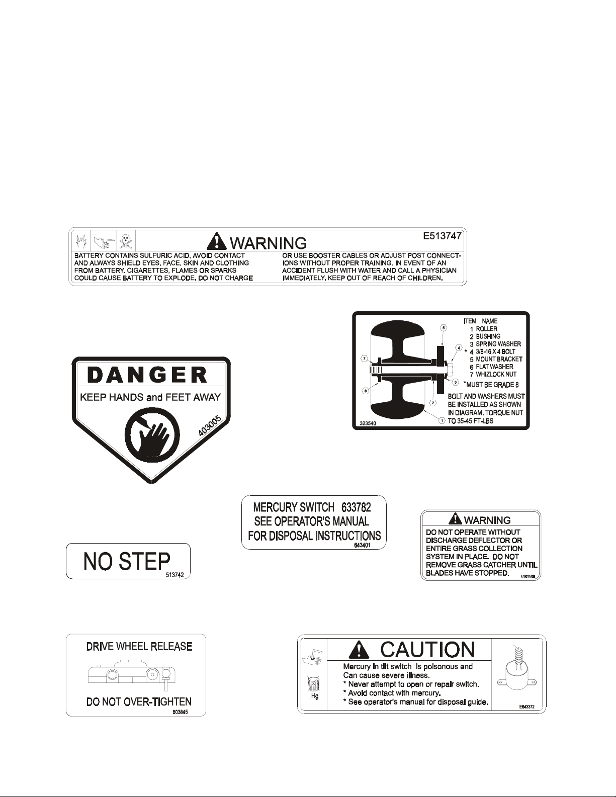
1.6 SAFETY SIGNS
1.6.1 Keep all safety signs legible. Remove all grease, dirt and debris from saf et y
signs and instructional labels.
1.6.2 Safety signs must be replaced if t hey are m issing or illegible.
1.6.3 When new components are installed, be sur e that current safety signs are
affixed to the replaced components.
1.6.4 New safety signs may be obtained from your authorized Exmark equipment
dealer or distributor or fr om Exmar k Mfg. Co. Inc.
1.6.5 Safety signs may be affixed by peeling of f the backing to expose the adhesive
surface. Apply only to a clean, dry surface. Smooth to remove any air bubbles.
1.6.6 Familiarize yourself with the following safety signs and inst r uct ion labels. They
are critical to the safe operation of your Exmark commercial mower.
PART NO. 513747
LOCATION: Top Center of Console Under
Front of Seat
PART NO. 403005
LOCATION: Left and Right Corners
of Mower Deck
PART NO. 513742
LOCATION: On Top of Mower Deck Belt
Shields, Left and Right Sides
PART NO. 603845
LOCATION: Under Seat, on Frame
Adjacent to Right Fuel Tank
PART NO. 323540
LOCATION: Left Front Corner Top of
Serial Nos. 220,000 & Higher
PART NO. 643401
LOCATION: On Tilt Switch
Serial Nos. 220,000 & Higher
PART NO. 643372
LOCATION: Top LH Side of Console, Under Front of Seat
Mower Deck
PART NO. 303508
LOCATION: Front Right Corner
Top of Mower Deck
- 6 -
Page 12
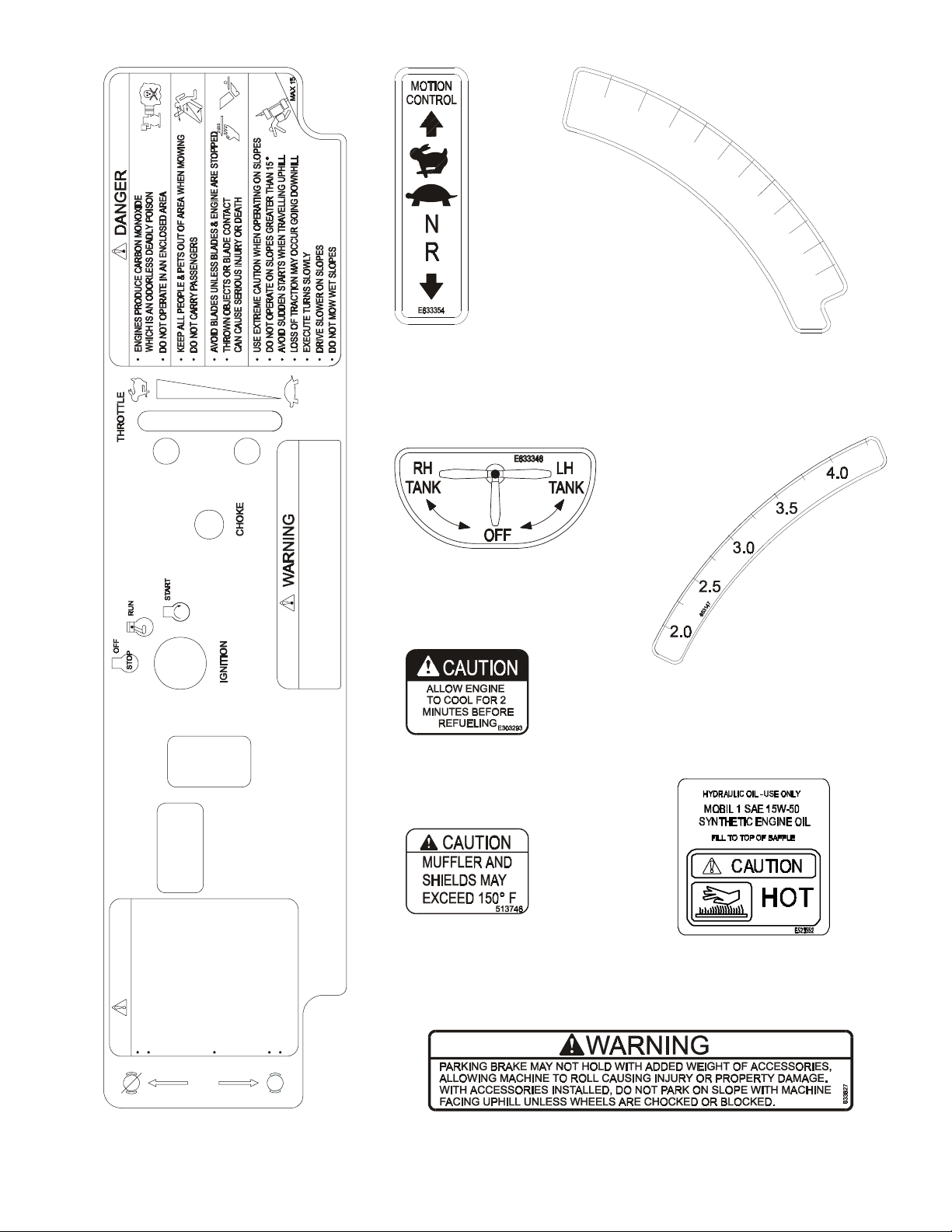
4.5
6
5
3
1
4
0
4.0
3.5
3.0
2.5
2.0
1.5
PTO
DISENGAGE PTO, ENGAGE PARK BRAKE, SHUT OFF ENGINE
AND REMOVE KEY BEFORE MAKING ADJUSTMENTS, SERVICING
OR CLEANING.
PART NO. 633354
LOCATION: Top of Console Left
and Right Side
PART NO. 633346
LOCATION: Below Center of
Console
PART NO. 303293
LOCATION: On Top of Fuel
Tanks
PART NO. 653140
LOCATION: RH Side of Cutting Height
Adjustment Plate
PART NO. 653147
LOCATION: Lefthand Side of Cutting
Height Adjustment Plate
CAUTION
READ MANUAL BEFORE OPERATING.
BEFORE STARTING ENGINE:
-PARK BRAKE MUST BE ENGAGED
-LEVERS MUST BE OUTWARD TO
NEUTRAL LOCK POSITION
-OPERATOR MUST BE IN SEAT
-PTO SWITCH MUST BE OFF
BEFORE LEAVING SEAT:
-PARK BRAKE MUST BE ENGAGED
-PTO SWITCH MUST BE OFF
-LEVERS MUST BE OUTWARD TO
NEUTRAL LOCK POSITION
KEEP ALL GUARDS & SHIELDS IN PLACE.
DO NOT PARK ON SLOPES UNLESS PARK
BRAKE IS ENGAGED.
P
RELEASE
PARK
BRAKE
P
ENGAGE
PART NO. 653245
LOCATION: Center of Console
653245
PART NO. 513746
LOCATION: Rear of Engine Deck,
Left and Right Sides
PART NO. 633827
LOCATION: LH Side Front Support Frame,
Below Brake Handle
- 7 -
PART NO. 523552
LOCATION: Top of Hydraulic
Reservoir
Page 13
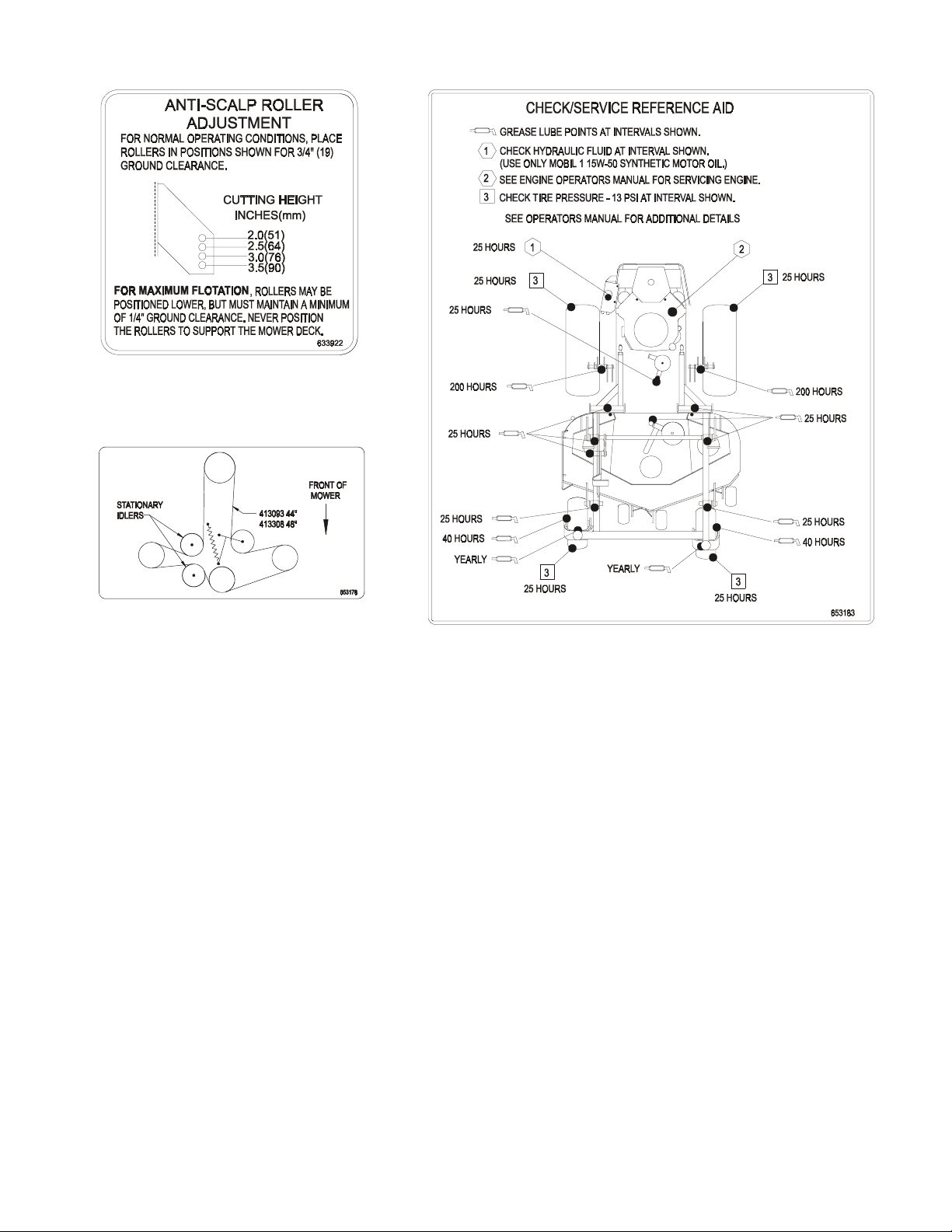
PART NO. 633922
LOCATION: Front Left Corner Top of
Mower Deck
PART NO. 653176
LOCATION: Left of Center on Mower Deck,
Under Floor Pan
2. SPECIFICATIONS
2.1 MODEL NUMBER:
PART NO. 653183
LOCATION: Bottom Side of Floor Pan
Serial Nos. 160,000 & Higher
Serial Nos. 190,000 & Higher
Serial Nos. 190,000
–219,999
Serial Nos. 220,000 & Higher
: LHP4417KA; LHP4818KC
: LHP4418KC
: LHP4819KA
: LHP4419KA; LHP4820KC; LHP4821KA;
LHP5220KC; LHP5223KC; LHP5223KA
2.2 ENGINE:
2.2.1 Engine Specifications: See Your Eng ine O wner’s Manual
2.2.2 RPM: Full Speed: 3600 RPM (No Load) Idle: 1500 RPM
2.3 FUEL SYSTEM
2.3.1 Capacity: 8 gal. (30 L.)
2.3.2 Type of Fuel: Regular
2.3.3 Fuel Filter: For Kohler: Replaceable in-line 15 Micron
For Kawasaki: Replaceable in-line
unleaded
gasoline, 87 octane or higher.
Kohler
Kawasaki
P/N 2405002
P/N 49019-2075
2.3.4 Fuel Shut-Off Valve: 1/4 turn increments (left tank , “OFF”, right tank)
2.4 ELECTRICAL SYSTEM
2.4.1 Charging System: Flywheel Alternator
- 8 -
Page 14

2.4.2 Charging Capacity: 15 amps
2.4.3 Battery Type: BCI Group U1
2.4.4 Battery Voltage: 12 Volt
2.4.5 Polarity: Negative Ground
2.4.6 Fuses: Two 20 amp blade type
2.4.7 Safety Interlock System: Oper at or m ust be in seat with
brake engaged
engine
.
Operator must be in seat
motion control levers are moved in
or
motion control levers out
, and
when Blades are engaged, brake is disengaged
(neutral lock)
or engine will stop.
Engine will stop if either the left, the right, or both levers are
neutral lock position while brake is engaged
.
Blades disengaged
to start
moved from
2.4.8 Tilt Switch: (Serial Nos. 220,000 & Higher) Shuts off the engine when the unit
is tilted more than 60° fr om horizontal.
2.5 OPERATOR CONTROLS
2.5.1 Steering and Motion Control:
Separate levers, on each side of the console, contr ol speed and dir ect ion of
travel of the respective drive wheels.
Steering is controlled by varying the position of the levers relative to each
other.
Moving motion control levers outward
neutral.
2.5.2 Blade Engagement Switch: Engag es elect r ic clutch (to drive belt) which
engages mower blades.
2.5.3 Parking Brake Lever: Sets br akes.
2.5.4 Deck Height Adjustment Lever: Set s cut ting height to desired position.
(in slots) locks the drive system in
,
,
2.6 SEAT
2.6.1 Type: Standard seat: high back , foam padded (internal spring
suspension)with arm rests.
Optional suspension seat: high back, low profile foam-in-place cushion
(dampened, adjustable spring suspension) with armrests.
2.6.2 Mounting: Hinged to tilt up for access to hydraulic pumps, battery and other
components. Held in tilted position with prop rod. Adjustable fore and aft seat
track.
2.6.3 Armrests: Standard seat: foam padded flip-up armrests.
Optional suspension seat: molded adjustable f lip- up armrests.
2.6.4 Seat Safety Switch: Incorporated into t he Safety Interlock System.
Time delay seat switch eliminates rough ground cut- outs.
2.7 HYDROSTATIC GROUND DRIVE SYSTEM
2.7.1 Hydrostatic Pumps: Two Hydro Gear BDP-10L variable displacement piston
pumps.
2.7.2 Wheel Motors: T wo Parker/Ross with 1 1/4” tapered shafts.
2.7.3 Hydraulic Oil Type: Synthetic Mobil 1 15W- 50.
2.7.4 Hydraulic Oil Capacity: 2.1 qt.(2.0 L.)
- 9 -
Page 15

2.7.5 Hydraulic Filter: Replaceable cartridge type.
P/N 513211: 10 microns, 18 psi bypass (Summer use above 32° F)
P/N 523541: 40 microns, 18 psi bypass (Winter use below 32° F)
2.7.6 Speeds: 44” & 48” units: 0 - 8.1 mph (13.1 km/hr) f orward.
0 - 4.2 mph (6.8 km/hr ) r everse.
52” units: 0 – 9.5 mph (15.3 km/hr) forward.
0 – 4.9 mph (7.9 km/hr) r everse.
2.7.7 Drive wheel release valves allow machine to be moved when the engine is not
running.
2.8 TIRES AND WHEELS
2.8.1 Tires:
Drive Tires 23 x 9.5-12 2 “Turfmaster ” 4 13 psi (90 kPa)
Front Caster Tires 13 x 5.00-6 2 Smooth 4 13 psi (90 kPa)
Size Qty Tread Ply Inflation
2.9 CUTTING DECK
2.9.1 Cutting Width: 44” deck 48” deck 52” deck
44 in.(111.8 cm) 47.24 in. (120.0 cm) 52 in. (132.1 cm)
2.9.2 Discharge: Side (Optional Mulch or Bag)
2.9.3 Blade Size:
(3 ea.)
2.9.4 Blade Spindles: solid steel spindles with 1” I.D. bear ings.
2.9.5 Deck Drive: Electric clutch mount ed on vert ical engine shaft. Blades are driven
by one “B” Section belt (w/self-tensioning idler) direct from the engine.
2.9.6 Deck: Full floating deck is at t ached t o out-front support fr am e.
Maximum turf protection is provided by three anti-scalp roller s on 44” &
48” decks and five anti-scalp rollers on 52” decks.
Deck design allows for bagging, mulching or side discharge.
2.9.7 Cutting Height Adjustment : an extra-long cushioned lever is used to adjust the
cutting height from 1 1/2” (3.8 cm) to 4.5” (11.4 cm . ) in 1/ 4” (.64 cm.)
increments for Serial No.s 190,000 and higher and 1/2” (1.3 cm) increments for
Serial No.s 160,000 through 189,999.
The cutting height adjustment handle has a transport position and all
adjustments can be made while the operator remains seated.
2.9.8 Mulching Kit: Optional.
44” deck 48” deck 52” deck
15.25 in. (38.7 cm) 16.25 in. (41.3 cm) 18.00 in. (45.7 cm)
2.10 DIMENSIONS
2.10.1 Overall Width:
w/44” Deck 43. 9 in. (111.5 cm) 47.4 in. (120.3 cm) 54.7 in. (138.9 cm)
w/48” Deck 45. 9 in. (116.6 cm) 50.3 in. (122.4 cm) 58.1 in. (147.6 cm)
w/52” Deck 47. 9 in. (121.7 cm) 54.3 in. (139.2 cm) 62.8 in. (159.5 cm)
2.10.2 O verall Length: w/44” & 48” decks: 74.1 in. (188. 2 cm )
2.10.3 O verall Height: w/44” & 48” decks: 40.0 in. (196.3 cm.)
Without deck
w/52” deck: 77.31 in. (196.3 cm)
w/52” deck: 40.0 in. (101.6 cm)
- 10 -
Discharge chute up Discharge chute down
Page 16

2.10.4 Tread W idth: (center to center of tires, widthwise)
w/44” Deck w/48” Deck w/52” Deck
Drive Wheels
Front Casters
2.10.5 Wheel Base: (center of caster tire to center of dr ive tire)
w/44” & 48” Deck: 45.9 in. (116.6 cm)
w/52” Deck: 47.2 in. (119.9cm)
2.10.6 Cur b Weight*: w/44” Deck: 887 lbs. (403.2 kg)
w/48” Deck: 907 lbs. (412.3 kg)
w/52” Deck: 1025 lbs. (464.9 kg)
* Note: Weight will vary slightly, depending on engine option.
34.4 in. (87.4 cm) 36.4 in. (92.5 cm) 38.4 in. (97.5 cm)
32.2 in. (81.8 cm) 32.2 in. (81.8 cm) 34.6 in. (87.9 cm)
2.11 TORQUE REQUIREMENTS
Bolt Location Torque Bolt Location Torque
Cutter Housing Spindle Nut......... 75-80 ft-lbs.
Blade Mounting Bolt .................... 75-80 ft-lbs.
Engine Deck/Front Frame Mount. 30-35 ft-lbs.
Anti-Scalp Roller Bolts ................. 40-45 ft-lbs.
Engine Mounting Bolts ................25-30 ft-lbs.
Wheel Motor Mounting Bolts........72-77 ft-lbs.
Wheel Hub Slotted Nut.... minimum125 ft-lbs.
3. ASSEMBLY INSTRUCTIONS
3.1 UNCRATE MOWER
3.2 INSTALL DRIVE WHEELS
3.2.1 Mount drive wheels with the valve stem to the outside of the unit. Secure using
four (4) 1/2-20 x 7/8”UNF wheel bolts (inst alled in hubs) or 1/2-20 wheel nuts
(installed on studs in hubs) for each wheel. Torq ue to 95 ft-lbs (128 N!M).
NOTE: Earlier models req uir e t he UNF wheel bolts. Later models have studs
installed in the wheel hub and require wheel nuts.
.
3.3 CHECK TIRE PRESSURE.
3.3.1 Check tire pressure in caster and drive tires. Pr oper inflation pressure for all
four (4) tires is 13 psi (90 k Pa) . Adjust if necessary.
3.4 INSTALL SEAT RETAINING ROD
3.4.1 Tilt seat up. Remove 5/16” nylock nut from bolt attaching seat ret aining rod to
seat frame. Remove ignit ion keys attached to bolt. Remove retaining rod from
seat and insert the “L” shaped end of t he r od into the hole directly above the
left-side hydraulic pump (the “L” m ust be positioned to the left or pointing up) .
Position the seat retaining rod to t he out side of the mounting tab on the seat
frame and secure with 5/16” x 1” bolt and nyloc nut. Tig hten until snug, then
loosen just enough so the rod pivots fr eely.
3.5 INSTALL MOTION CONTROL LEVERS
3.5.1 Loosen and remove the two (2) 3/8” x 1” bolts and spring disc washers which
attach the motion control levers to the control arm shafts for shipping and the
two (2) 3/8” x 1” bolts and spring disc washers which are screwed into the
control arm shafts.
a) Install the lef t m otion control lever onto the control arm shaft (See Fig 1)
on the left side of the console. Place the lever (with the mounting plate
towards the rear) on the
the bolts and washers. Position the lever so the bolts are in the center of
the slots on the lever mounting plate and tig hten until snug. Repeat on
opposite side of unit.
.
outside
.
of the control arm shaft and secure with
- 11 -
Page 17

If the levers do not align with each other, when in the neutral position,
(See Fig 2) loosen the hardware and make the appropr iat e adjustment by
sliding/tilting the lever(s ) forward or backward until properly aligned and
tighten hardware.
MOTION
CONTROL
LEVER
MOUNT PLATE TO
THE REAR & OUTSIDE
OF ARM SHAFT
LEVERS IN
ALIGNMENT
FIG. 1 FIG. 2
CONTROL ARM SHAFT LEVER ALIGNMENT
b) If the ends of the levers hit against each other, while in the drive position
(levers rotated in as far as possible), make adjustments by moving the
levers outwards to the neutral lock position and carefully bend them
outward. Move them back to the drive position and check for clear ance,
repeat if necessary.
3.6 POSITION DISCHARGE CHUTE.
3. 6.1 Loosen t wo (2) 5/ 16” nylock nuts attaching discharge chute. Lower the discharge
chute into position. Retighten nylock nut s unt il chute is snug but can pivot freely.
3.7 SERVICE ENGINE.
Engine is shipped with oil, check oil level and if necessary fill to t he appropriate
level with SAE 10W-30 or 10W-40, AP1 service class SF or SG f or oper ating in
temperatures above 0° F (-18° C). See Engine Operator' s Manual.
3.8 SERVICE BATTERY.
Machine is shipped with a dry battery.
3.8.1 Remove battery from machine. Tilt seat up to gain access to the battery.
Disconnect
battery cables -
negative(black) cable first
. Remove battery
hold-down and lift battery out.
3.8.2 Place battery on a level surface and r em ove vent caps.
DANGER
POTENTIAL HAZARD
♦ Battery electrolyte contains sulfuric acid, which is
poisonous and can cause severe burns
WHAT CAN HAPPEN
♦ Swallowing electrolyte can be fatal or if it t ouches skin
can cause severe burns.
HOW TO AVOID THE HAZARD
♦ Wear safety glasses to shield eyes, and rubber gloves
to protect skin and clothing when handling elect r olyte.
♦ Do not swallow electrolyte.
♦ Fill the battery where clean water is available for
flushing skin.
- 12 -
Page 18

DANGER
POTENTIAL HAZARD
♦ Charging the battery may produce explosive gasses
WHAT CAN HAPPEN
♦ Battery gasses can explode causing serious injury.
HOW TO AVOID THE HAZARD
♦ Keep sparks, flames, or cigarettes away from battery.
♦ Ventilate when charging or using battery in an
enclosed space.
♦ Make sure venting path of battery is always open once
battery is filled with acid.
3.8.3 Fill cells with battery grade sulfuric acid (1. 265 specific gravity) to halfway
between top of separators and bottom of vent well.
3.8.4 Let battery stand f or 1/2 hour after filling . If battery acid level has fallen, refill to
level above plates.
3.8.5 Charge the batt er y at 4 t o 5 am ps for 3-5 hours.
3.8.6 After charging, install vent caps and wash off any acid with water and dry battery.
CAUTION
POTENTIAL HAZARD
♦ If the ignition is in the “ ON” position there is potential
for sparks and engag em ent of components.
WHAT CAN HAPPEN
♦ Sparks could cause an explosion or moving parts
could accidentally engage causing personal injury.
HOW TO AVOID THE HAZARD
♦ Be sure ignition switch is in the “OFF” position.
3.8.7 Install battery in machine and secure battery hold-down.
Connect battery cables -
cable and green/white wire. Slip insulator boot over the positive terminal.
NOTE:
available, follow steps 3.8.1 through 3.8.4 and install as described in 3.8.7. Then
run the vehicle continuously for 20 to 30 minutes to sufficiently charge the battery.
After charging , if battery acid level has fallen, ref ill bat tery with clean drinking water
(distilled water is preferred – if available).
If time does not permit char ging the battery, or if charging equipment is not
positive (red) cable first
, then the negative (black)
DO NOT
over-tighten
.
PART NO. 513747 LOCATION: Top Center of Console
Under Front of Seat
- 13 -
Page 19

3.9 SERVICE HYDRAULIC OIL
The machine is shipped with hydraulic oil filled to the top of the baffle in reservoir. Run
the machine for approximately 15 minutes to allow any extra air to purge out of the
hydraulic system. Check hydraulic reservoir and if necessary f ill t he r eservoir to the
appropriate level with Mobil 1 15W-50 synthetic motor oil.
4. OPERATION INSTRUCTIONS
4.1 CONTROLS
4.1.1 Familiarize yourself with all controls before operat ing the mower.
4.1.2 Motion Control Levers: Located on each side of the console.
The left lever controls the flow of hydraulic oil from the left hydrosta t ic pum p t o
the left drive wheel motor. The r ight lever controls the flow of hydraulic oil fr om
the right hydrostatic pump to the right drive wheel motor.
IMPORTANT: To begin movement (forward or backward) the operator
must be in the seat, the brake lever must be disengaged (pushed down)
before the motion control levers can be moved in or the engine will kill.
When levers are center ed in the T-slot the drive system is in the neutral
position. W it h levers m oved out in t he T-slot the drive system is in the
lock
position (See Fig 3).
neutral
FIG. 3
MOTION CONTROL POSITIONS
By moving both levers an
the machine can be caused to move forward or backward in a straight line.
Movement of the
a forward direction. Movement of the
drive wheel
levers back to the neutral position.
turn left
To
slow the left drive wheel. To
lever
back toward neutral.
To make a
holding the right lever slight ly ahead of neutral.
To make a
position while holding the left lever slightly ahead of the neutral position.
Pulling the
wheels to rotate in a
into reverse from neutr al) .
To turn to the left while backing, move the left lever for ward toward neut r al. To
turn to the right while backing , m ove the right lever forward toward neutral.
levers back
left lever forward
to rotate in a forward direction. To
while moving forward, move the
zero turn
zero turn
equal
amount forward or back from the neutral position
will cause the
right lever forward
turn right
to the
to the
reverse
left
, pull the left lever back beyond neutra l while
right
, pull the right lever back beyond the neutral
from the neutral position will cause the respective drive
direction (spring tension can be f elt when moving
while moving forward, move the
left drive wheel
stop
forward travel, pull the
left lever
to rotate in
will cause the
back toward neutral to
right
right
- 14 -
Page 20

POTENTIAL HAZARD
♦ Machine can spin very rapidly by positioning one lever
too much ahead of the other.
WHAT CAN HAPPEN
♦ Operator may lose control of the machine, which may
cause damage to the machine or injury.
HOW TO AVOID THE HAZARD
♦ Use caution when making turns.
♦ Slow the machine down before making sharp turns.
4.1.3 Blade Engagement Switch: Located just left of cent er on the console (left side
of ignition switch). Switch must be
engage the blades. Switch is pushed in to the “
blades.
4.1.4 Choke Control: Located at center of console (right side of ignition switch).
Choke is used to aid in starting a cold engine. The choke control is
to be in the “ON” position and
run a warm engine with choke in the “ON” position.
4.1.5 Throttle Control: Located on console just right of center.
Throttle is used to control engine speed. Moving throttle lever
increase engine speed and moving throttle lever
engine speed.
4.1.6 Brake Lever: Located on left side of the console. The brake lever engages a
parking brake on the drive wheels.
Pull
the lever up and
Push
the lever
When parking on a steep slope, the wheels must be chocked or blocked in
addition to the brake being engaged. The unit must be tied down and brake
engaged when transporting.
forward
CAUTION
rearward
down
and
pulled out
pushed in
engage
to
disengage
to
to the “
STOP
to be in the “
to the rear
the brake.
the brake.
ROTATE
” position to stop the
OFF
” position to
pulled out
” position.
forward
will decrease
DO NOT
will
4.1.7 Ignition Switch: Located on the lower center of console.
The ignition switch is used to start and stop the engine. The switch has three
positions “OFF”, “ON” and “START”. Insert the key into switch and rotate
clockwise to the “ON” position.
Rotate clockwise to the next position to engage the starter (key must be held
against spring pressure in this position) .
Operator must be in seat with brake engaged, moti on cont rol levers out
(neutral lock position) and blade engagement switch “OFF” to start
engine.
4.1.8 Hour Meter: Located left on center of console. The hour meter is connected to
a pressure switch installed in the engine block and it recor ds t he num ber of
hours that the engine has run. If ignition switch is left on without engine
running, hour meter will not run.
NOTE: This switch is not a low oil sensor and will not alert the operator if the
engine oil is low.
4.1.9 Fuel Shut-Off Valve: Located directly below center of console.
- 15 -
Page 21

The fuel shut-off valve is used to shut off the f uel when the machine will not be
used for a few days, during transport to and from the jobsite, and when parked
inside a building. The valve has three positions, each position made in 1/ 4
turn increments.
Valve handle down is the “OFF” position. Rotate valve handle 1/4 turn right
(from “Off” position) for fuel flow from the right tank. Rotate valve handle 1/4
turn left (f rom “Off” posit ion) for fuel flow from the left tank.
4.1.10 Dr ive Wheel Release Valves: The drive wheel release valve levers are 1/420x2 screws covered with a black vinyl grip located on the right front corner of
the hydrostatic pumps. Drive wheel release valves are used to release the
hydrostatic drive system to allow the machine to be pushed without the engine
running. Tilt seat up to gain access to pumps.
Loosen both valves one turn to release drive system.
Tighten to reset system.
DO NOT overtighten. DO NOT t ow machine.
4.2 PRE-START
4.2.1 Fill fuel tanks. For best r esults use only clean, fresh regular grade
gasoline with an octane rating of 87 or higher. Regular grade leaded gasoline may
also be used; however, combustion chamber and cylinder head will require more
frequent service. See Engine Owner's Manual.
Never fill the fuel tank so t hat the fuel level rises above a level that is 1/2” below
the bottom of the filler neck to allow for fuel expansion and prevent fuel spillage.
DO NOT
add oil to gasoline.
DANGER
POTENTIAL HAZARD
♦ In certain conditions gasoline is extremely flammable
and highly explosive.
WHAT CAN HAPPEN
♦ A static charge can ignite g asoline vapors. A fire or
explosion from gasoline can burn you, others, and
cause property damage.
HOW TO AVOID THE HAZARD
♦ Purchase and store gasoline only in an approved
container.
♦ Always place gasoline containers on the ground away
from your vehicle before f illing.
♦ Do not fill gasoline containers inside a vehicle or on a
truck or trailer bed because inter ior car pets or plastic
truck bed liners may insulate the container and slow
the loss of any static charge.
♦ When practical, r emove gas-powered equipment from
the truck or trailer and refuel the equipment with its
wheels on the ground.
♦ If this is not possible, then refuel such equipment on a
truck or trailer from a portable container, rather t han
from a gasoline dispenser nozzle.
♦ If a gasoline dispenser nozzle must be used, keep the
nozzle in contact with the rim of the fuel tank or
container opening at all times until fueling is complete.
unleaded
- 16 -
Page 22

4.2.2 Make sure you understand the controls, their locations, their functions, and
their safety requirements.
4.2.3 Refer to Maintenance, Section 5, and perf or m all the necessary inspection and
maintenance steps.
4.3 MOWING
4.3.1 Open fuel shut -off valve (left or right tank).
4.3.2 Starting Engine:
blade engagement switch disengaged, and the moti on cont rol levers out
(neutral lock position).
cold
On a
“FAST” positions and pull
the “start” position. Release the switch as soon as the engine starts.
IMPORTANT:
(10) seconds at a time. If the engine does not start, allow a 60 second
cool-down period between starting attempts. Failure to f ol low these
guide lines can burn out the starter motor.
After starting a cold engine, gradually return choke to t he “ O FF” position as the
engine warms up.
On a
“FAST” positions and leave the
4.3.3 Engaging Electric Blade Clutch: The electric blade clutch push-pull switch
engages the cutting blades. Be sur e t hat
and discharge area
IMPORTANT: Operator must be in seat before the blades can be engaged.
Set throttle to "midway" position. Pull outward on the switch to the “ROTATE”
position. Accelerate to full throttle to begin mowing.
4.3.4 Stopping Electric Blade Clutch: Set t he throttle to the “IDLE” position. Push in
on the switch to the “STOP” position stopping the cutting blades.
4.3.5 Stopping Engine: Bring unit to a
move motion control levers out
brake
Adjust engine speed to 1/2 throttle or higher.
Rotate ignition switch to “OFF” posit ion. Rem o ve the key to prevent children or
other unauthorized persons from star t ing engine.
Close fuel shut-off valve when machine will not be used for a few days, when
transporting, and when the unit is park ed inside a building.
engine, place the
warm
.
Operator must be in seat
throttle midway
choke
DO NOT
engine, place the
crank the engine continuously for more than ten
throttle midway
before engaging
with the
between the “SLOW” and
to the “ON” position. T ur n ignition switch to
choke
in the “OFF” position.
all
persons are
cutting blades.
full stop. Disengage
to the
neutral lock
brake engaged
between the “SLOW” and
clear
the cutting blades,
position and
, the
of mower deck
set parking
4.4 TRANSPORTING
4.4.1 Transport ing a Unit: Use a heavy-duty trailer or truck to tr anspor t the machine.
Lock brake and block wheels. Securely fasten the machine to the trailer or
truck with straps, chains, cable, or ropes. Be sur e that the trailer or truck has
all necessary lighting and marking as required by law.
Secure a trailer with a safety chain.
- 17 -
Page 23

POTENTIAL HAZARD
♦ This unit does not have proper turn signals, lights,
reflective markings, or a slow moving vehicle emblem.
These items are required t o dr ive on a public str eet or
roadway.
WHAT CAN HAPPEN
♦ Driving on a street or roadway without such equipment
is dangerous and can lead to accidents causing
personal injury.
♦ Driving on a street or roadway without such equipment
may also be a violation of State laws and the operator
may be subject to traffic t ick ets and/or fines.
HOW TO AVOID THE HAZARD
♦ Do not drive a unit on a public street or roadway.
CAUTION
POTENTIAL HAZARD
♦ Loading a unit on a trailer or truck increases the
possibility of backward tip-over.
WHAT CAN HAPPEN
♦ Backward tip-over of the unit could cause serious
injury or death.
HOW TO AVOID THE HAZARD
♦ Use extreme caution when operating a unit on a ramp.
♦ Use only a single, full width ramp; DO NO T use
individual ramps for each side of the unit.
♦ If individual ramps must be used, use enough ram ps t o
create an unbroken ramp surf ace wider than t he unit .
♦ DO NOT exceed a 15° angle between ramp and
ground or between ramp and trailer or truck.
♦ Avoid sudden acceleration while driving unit up a ramp
to avoid tipping backward.
♦ Avoid sudden deceleration while backing unit down a
ramp to avoid tipping backward.
WARNING
4.4.2 Loading a Unit: Use extreme caution when loading units on tr ailer s or trucks.
One full width ramp that is wide enough to extend beyond the rear tir es is
recommended instead of individual ramps f or each side of the unit. The lower
rear section of the tractor frame extends back between the rear wheels and
serves as a stop for tipping backward. Having a full width ramp provides a
surface for the frame members to contact if t he unit starts to tip backward. If it
is not possible to use one full width ramp, use enough individual ramps t o
simulate a full width continuous ramp.
- 18 -
Page 24

Ramp should be long enough so that the angles between the ramp and the
ground and the ramp and the trailer or truck do not exceed 15°. A steeper
angle may cause mower deck components to get caug ht as t he unit moves
from ramp to tr ailer or truck. Steeper angles may also cause the unit to tip
backward. If loading on or near a slope, position the trailer or truck so it is on
the down side of the slope and the ramp extends up the slope. This will
minimize the ramp angle. The tr ailer or truck should be as level as possible.
DO NOT attempt t o turn the unit while on the ramp, you may lose control and
drive off the side.
Avoid sudden acceleration when driving up a ramp and sudden deceleration
when backing down a ramp. Both maneuvers can cause the unit to tip
backward.
5. MAINTENANCE & ADJUSTMENTS
5.1 PERIODIC MAINTENANCE
5.1.1 Check engine oil level:
a) Make sure engine is stopped and on a level surface.
b) Check with engine cold.
c) Clean ar ea ar ound dipst ick. Remove dipstick and wipe oil off. Reinsert
the dipstick. Do not screw into place. Remove the dipstick and r ead t he
oil level.
d) If the oil level is low, wipe off the area ar ound t he oil fill cap, remove cap
and fill to the “F” mark on the dipstick. Use oil as specified in or in Engine
Owner’s Manual.
DO NOT
IMPORTANT:
“L” mark on the dipstick, or over the “F” mark.
5.1.2 Clean engine air cooling system :
overfill.
DO NOT
Service Interval: Daily or more often
operate the engine with the oil level below the
in dry conditions
Service Interval: Daily
CAUTION
POTENTIAL HAZARD
♦ Excessive debris can cause the engine and hydraulic
system to overheat.
WHAT CAN HAPPEN
♦ Excessive debris around the engine cooling air intake
and inside of the pump compartment can cr eate a fire
hazard.
HOW TO AVOID THE HAZARD
♦ Clean all debris from around the eng ine and hydraulic
pumps daily.
a) Stop engine and remove key.
b) Clean all debris from rotating engine air int ake screen and from around
engine shrouding.
- 19 -
Page 25

5.1.3 Clean grass build-up under deck.
Service Interval: Daily
a) Stop engine and remove key.
b) Raise deck to the transport (4.5” cutting height) position.
Lift the front of unit and support unit using jack st ands or equivalent
support.
CAUTION
POTENTIAL HAZARD
♦ Raising the mower deck for service or m aint enance
relying solely on mechanical or hydraulic jacks could
be dangerous.
WHAT CAN HAPPEN
♦ The mechanical or hydraulic jacks may not be enough
support or may misfunction allowing the unit to fall,
which could cause injury.
HOW TO AVOID THE HAZARD
♦ DO NOT rely solely on mechanical or hydraulic jacks
for support. Use adequate jack stands or equivalent
support.
c) Clean out any gr ass build- up from underside of deck and in deck
discharge chute.
5.1.4 Check mower blades.
a) St op engine and remove key.
b) Lift deck and secure in raised position as stated in Section 5. 1.3 .
c) Inspect blades and sharpen or replace as required.
d) Torque blade bolts as shown. Be sure the spring disk washer cone is
installed toward the bolt head.
(See Figure 4).
Service Interval: Daily
FIG. 4
BLADE BOLT INSTALLATION
- 20 -
Page 26

5.1.5 Check safety interlock system.
Service Interval: Daily
a) Check starting circuit. Starter
parking brake
engaged,
levers moved out in the
Try to start with
disengaged
must not crank
Try to start with
disengaged
starter
must not crank
Try to start with
engaged
and motion control levers in the
must not crank
Try to start with
operator out of seat
and motion control levers in
.
operator in seat
and motion control levers in the
.
operator in seat
.
operator in seat
disengaged, and the left motion control lever in,
crank,
starter
repeat again with the
must not crank.
b) Check kill circuits. Run engine at one-third throttle,
brake and
stop
raise off
of seat (but do not get off of machine) engine
after approx. 1/2 second has elapsed (seat has t im e delay k ill switch
to prevent cut-outs on rough terr ain) .
Run engine at one-third throttle,
seat (but do not get of f of machine) engine
has elapsed.
Run engine at one-third throttle, with brake disengaged, move levers in
and raise off seat (but do not get off of m achine) engine
1/2 second has elapsed.
Again, run engine at one-thir d throttle, brake
motion control lever in
Repeat again moving the
engine
NOTE: If machine
must stop
does not
whether operator is
Contact your authorized EXMARK SERVICE DEALER.
should
crank with
cutting blades
neutral lock
position.
, parking brake
, parking brake
, parking brake
right lever in
engage cutting blades
disengaged
, parking brake
neutral lock
neutral lock
operator in seat
disengaged,
neutral lock
engaged,
engaged,
, then with
disengage
must stop
and motion control
engaged
, blades
position - starter
blades
position -
blades
position - starter
blades
starter
must not
both levers in
parking
raise off
and
after 1/2 second
must stop
- engine
must stop.
right lever in
engaged,
, then moving
on seat or not
and move
both levers in
.
pass any of these tests, do not operate.
,
-
must
of
after
left
-
IMPORTANT: It is essential that operator safety mechanisms be
connected and in proper operating condition prior to use for mowing.
5.1.6 Check for loose hardware.
Service Interval: Daily
a) Stop engine and remove key.
b) Visually inspect machine for any loose hardware or any other possible
problem. Tighten hardware or correct the problem before operating.
5.1.7 Service air cleaner.
Service Interval: 25 hrs.
more often under severe conditions.
a) Stop engine and remove key.
b) Remove air cleaner compartment cover.
- 21 -
Page 27

c) Remove foam pr e- cleaner element and wash in warm water with
detergent. Rinse until all traces of detergent are eliminated and sq ueeze
out excess water
squeeze out excess oil.
d) Check paper element.
dislodge any dirt.
element.
Replace if dirty, bent or damag ed.
e) Reinstall foam pre-cleaner to paper element , then reinstall paper element
and cover.
5.1.8 Change engine oil:
NOTE:
a) Stop engine and remove key.
b) Drain oil while engine is warm from operation.
c) Replace the oil filter
d) Clean around oil fill cap and remove cap. Fill to specified capacity and
e) Start the engine and check for leaks.
5.1.9 Check hydraulic oil level:
a) Stop engine.
b) Clean area around hydraulic reservoir cap and remove cap.
Use only Mobil 1 15W-50 synthetic motor oil.
Change oil and filter af t er first five(5) hrs. of operation
unscrew filter to remove. Before reinstalling new filter, apply a thin
coating of oil on the surface of the rubber seal. Turn filter clockwise until
rubber seal contacts the filter adapter then tighten filter an additional 2/3
to 3/4 turn.
replace cap. Use oil recommended in engine owner’s manual.
overfill.
Oil level should be to the top of the baf fle inside the tank. If not , add oil.
(DO NOT wring).
DO NOT
Service Interval: 100 hrs
Service Interval:
Gently
every other
tap the flat side of the paper element to
wash or use pressurized air to clean paper
Air dry. Saturate with engine oil and
.
oil change. Clean around oil filter and
DO NOT
40 hr.
POTENTIAL HAZARD
♦ Hydraulic fluid escaping under pressure can penetrat e
skin and cause injury.
WHAT CAN HAPPEN
♦ Fluid accidentally injected into the skin must be
surgically removed within a few hours by a doctor
familiar with this form of injury or gangrene ma y result .
HOW TO AVOID THE HAZARD
♦ Make sure all hydraulic fluid hoses and lines are in
good condition an all hydraulic connections and fittings
are tight before applying pressure to hydraulic system.
♦ Keep body and hands away from pinhole leaks or
nozzles that eject high pressure hydraulic fluid.
♦ Use cardboard or paper to find hydraulic leaks.
♦ Safely relieve all pressure in the hydraulic system
before performing any work on the hydraulic system.
WARNING
- 22 -
Page 28

5.1.10 Check tire pressures:
Service Interval: 40 hrs.
a) Stop engine and remove key.
b) Inflate all four tires to 13 psi (90 kPa).
5.1.11 Check battery electrolyte level:
Service Interval: 40 hrs.
a) Stop engine and remove key.
b) Tilt seat up.
c) Remove vent caps fr om battery. Fill with water (distilled is recommended)
to bottom of vent wells and replace vent caps.
d) See Assembly Section 3.8, for servicing a new battery.
PART NO. 513747 LOCATION: Top Center of Console
5.1.12 Check condition of belts:
Service Interval: 40 hrs.
a) Stop engine and remove key.
b) Check under engine deck to check pump drive belt.
c) Remove left and right belt shields on deck and lift up floor pan to inspect
deck drive belt.
d) See Sections 5.2.3 and 5.2.4, for belt adjustment.
5.1.13 Lubr icat e grease fittings:
Service Interval: Refer to chart.
a) Stop engine and remove key.
b) Lubricate fittings with one to two pumps of SAE No. 2 m ulti-purpose gun
grease.
Refer to the following chart for fitting locations and lubricat ion schedule.
Under Front of Seat
LUBRICATION CHART
FITTING
LOCATIONS
1. Front Casters 2 2 40 hours
2. Front Caster Pivots 0 2
3. Height Adj. Shaft Brngs. 1 5 40 hours
4. Deck Drive Belt Idler Arm 1 1 40 hours
5. Brake Brackets 1 2 200 hours
6. Pump Drive Belt Idler Arm 1 1 40 hours
7. Deck Rear Struts 1 2 40 hours
∗∗∗∗ More often if operating under severe condit ions.
∗∗
∗∗ See 5.1.13 Section c) for special lubricat ion inst ructions.
∗∗∗∗
INITIAL
PUMPS
- 23 -
NO. of
PLACES
SERVICE
INTERVAL
∗∗yearly
∗
Page 29

No. 6 (Pump Drive Belt Idler Arm)
Located Under Deck - Grease through hole in
top of deck, between pumps.
No. 4 & 6 (Idler Arms)
Monthly dissasemble belt and spring and
grease under a “NO LOAD” condition.
c) Lubricate front caster pivots once a year. Remove hex plug and cap.
Thread grease zerk in hole and pump with grease until it oozes out
around top bearing. Remove grease zerk and t hread plug back in. Place
cap back on.
5.1.14 Lubr icat e seat switch actuator:
Service Interval: 160 hrs.
a) Stop engine and remove key.
b) Tilt seat up.
c) Lubricate switch actuator rod with spray type lubricant or light oil.
5.1.15 Lubr icat e brake handle pivot:
Service Interval: 160 hrs.
a) Stop engine and remove key.
b) Lubricate bronze bushings on brake handle pivot with a spray type
lubricant or light oil.
5.1.16 Lubr icat e br ake rod bushings:
Service Interval: 160 hrs.
a) Stop engine and remove key.
b) Tilt seat up.
c) Lubricate bronze bushing s on each end of brake rod shafts with a spray
type lubricant or a light oil. One shaft is located under the console. The
other is below and behind the seat.
5.1.17 Lubr icat e m o t ion cont r ol br onze bushing s:
Service Interval: 160 hrs.
a) Stop engine and remove key.
b) Tilt seat up.
c) Lubricate bronze bushing s on flange bearings securing the motion control
arm shafts with a light oil or a spr ay type lubricant .
5.1.18 Rem ove engine shrouds and clean cooling fins:
Service Interval: 80 hrs.
a) Stop engine and remove key.
b) Remove cooling shrouds from engine and clean cooling fins. Also clean
dust, dirt and oil from external sur faces of engine which can cause
improper cooling.
c) Make sure cooling shr ouds ar e r einstalled. Operating the engine without
cooling shrouds will cause engine damage due to overheating.
- 24 -
Page 30

5.1.19 Check spark plugs:
Service Interval: 160 hrs.
a) Remove spark plugs, check condition and reset gaps, or replace with
new plugs. See Engine Owners Manual.
5.1.20 Change fuel filter:
Service Interval: As Required
a) A fuel filter is installed between the f uel tanks and the engine. Replace
when necessary.
For Kohler engines use
For Kawasaki engines use
5.1.21 Change hydraulic system filter:
Service Interval: After First 250 hrs.
Kohler
P/N 2405002.
Kawasaki
P/N 49019-2075
Then yearly thereafter
NOTE: Use only Exmark Part No. 513211 for Summer use above
No. 523541 for Winter use below 32°
F.
a) Stop engine and remove key.
b) Locate filter under right rear corner of engine deck.
c) Carefully clean area around filter. It is
contamination
enter hydraulic system.
d) Unscrew filter to remove and allow oil to drain from reservoir.
IMPORTANT
: Before reinstalling new f ilter, fill it with Mobil 1 15W - 50 and
apply a thin coat of oil on the surface of the rubber seal.
Turn filter clock wise until rubber seal contacts the filter adapter then
tighten the filter an addit ional 2/ 3 to 3/4 turn.
e) Fill reservoir as stated in Section 5.1.9.
f) Raise t he r ear of machine up and support with jack stands (or equivalent
support) just high enough t o allow drive wheels to turn freely.
g) Start engine and move throttle control ahead to f ull throttle position.
Move the speed control levers to the full speed and run for several
minutes. Shut down machine and recheck oil level.
Do not change hydraulic system oil (except for what can be drained when
changing filter), unless it is felt the oil has been contaminated or been
extremely hot.
Changing oil unnecessarily
could
damage
contaminates into the system.
5.1.22 Wheel hub - slotted nut torque specification.
When tig ht ening the slotted nut on the wheel motor tapered shaf t:
a) Torque the slotted nut to 125 f t. lbs.
b) Check distance from bottom of slot in nut to inside edge of hole. Two
threads (0.1”) or less should be showing.
c) If more than two threads (0.1”) are showing remove nut and install
washer (PN 523157) between hub and nut.
d) Torque the slotted nut to 125 f t. lbs.
e) Then tighten the nut until the next set of slots line up with the cross hole
in the shaft. Replace cotter pin.
32° F or Part
important
that
no dirt
or
hydraulic system by introducing
- 25 -
Page 31

5.1.23 Fuel Tank – mounting hardware specification.
When installing the nuts onto the fuel tank st uds, fully tighten the nyloc nut and
back off 1/2 t ur n. This allows for normal fuel tank expansion and contraction
with changes in temperature and fuel levels.
5.1.24 Thread locking adhesives such as “Loctite 242” or “Fel-Pro, Pro-Lock Nut
Type” are used on the following fasteners:
a) Pump drive sheave setscrews.
b) Square head setscrews on Hydro pump control arms.
c) Sheave retaining bolt in the end of engine crankshaft .
Adhesives such as “Loctite RC/609 or RC/680” or “Fel-Pr o Pr o- Lock Retaining
I or Retaining II” are used on the following:
b) Fuel tank studs where studs are inser t ed int o tank.
5.1.25 Dielect r ic grease is used on all blade type electrical connections to prevent
corrosion and loss of contact.
5.2 ADJUSTMENTS
IMPORTANT: Disengage blade clutch, shut off engine and remove key
before servicing, cleaning or making adjustments.
5.2.1 Cutting Height Adjustm ent .
a) Stop machine and move drive levers out to neutral lock position.
b) Disengage blades.
c) Raise the deck lever t o t he t ransport position (also the 4.5” cutting height
position). See Fig 5.
NOTE: When changing cutting height positions, al ways come to a
complete stop and disengage the mower bl ades.
FIG. 5
CUTTING HEIGHT POSITION
d) Insert height adjustment pin into hole corresponding to desired cutting
height and install hairpin cotter. See decal on deck lift plate.
e) Move lever out of transport (or 4.5” cutting height) position and down onto
height
adjustment pin to mow at selected height.
f) T o transport, move lever back up to transport (or 4.5” cutting height)
position.
g) Adjust anti-scalp rollers for Nor m al Operating Conditions. Stop engine and
remove key. Place rollers in one of t he posit ions shown in Fig. 6. Rollers
will maintain 3/4 in. (19 mm) clearance to the ground to minimize gouging
and roller wear or damage.
For Maximum Deck Flotation,
place rollers
one hole position lower. Rollers should maintain 1/4 in. (6.4 mm) minimum
clearance to ground.
Do Not
adjust rollers to support the deck. Be sure bolt
is tightened properly or loss of anti-scalp roller may result.
- 26 -
Page 32

ANTI-SCALP ROLLER ADJUSTMENT
5.2.2 Deck Leveling:
a) Position mower on a flat surface.
b) Stop engine and remove key.
c) Check t ire pr essure of all four (4) tires. If needed, adjust to 13 psi (90 kPa).
d) Set anti-scalp rollers to top holes or rem ove them com pletely for this
adjustment.
e) Raise the deck to the 4.5” height position and take as much force as
possible off of the two large deck lift springs by loosening the nut s at t he
front of each spring . See Fig. 7.
f) Lower the deck to the 1-1/2” height position. Place two 1-5/16” thick
blocks under the rear edge of the cutting deck skirt; one on each side of
the cutting deck. Place a 1-1/8” block under the center front edge, but not
under the anti-scalp roller brackets.
g) Loosen the two (2) bottom chain bolts in slots at the rear of the cutting
deck. Loosen four (4) nut s which secure f ront swivels (two per side), until
front chains are loose and front of deck is supported by the 1-1/8” block .
Do not loosen fr ont chain hardware.
h) When hardware is loosened, remaining tension in the large support
springs will tend to rotate the deck lift handle up, out of the 1 1/2”
position. Press down on the rear deck support arm ( as shown in Fig. 7) t o
firmly return the deck lift handle to the 1 1/2”
deck lift handle. While continuing to press down,
rear chains and tighten hardware at the bottom of
Downward pressure may now be released.
i) On lef t side, adjust front swivel using the locking nut behind the swivel
until the front chain is tig ht and all slack is removed from linkage. Do not
lift front of deck off 1-1/ 8” block. Secure front swivel using locking nut in
front of swivel. Repeat for right side.
FIG. 6
position.
DO NOT
take the slack out of t he
the rear chains.
push on
FIG. 7
SWIVEL ADJUSTMENT
SPRING COMPRESSION ADJUSTMENT
- 27 -
Page 33

j) Recheck that blocks fit just snugly under the deck skirt and that the
tension on all the chains are approximately equal. Make sure all chain
attachment bolts are tight .
k) Raise deck lift lever to the 4.5” cutting height position (also transport
position, See Fig 5. Adjust spring com pression until proper distance is
obtained between the two washers (See Fig 7) by turning the nut at the
front of each spring. Lock nuts in position with jam nuts.
l) Reposition anti- scalp r o ller s and tighten securely.
NOTE: When above adjustments have been made, the front of
the deck will be slightly lower than the rear of the deck.
5.2.3 Pump Dr ive Belt Tension.
Self-tensioning - No adjustment necessary.
5.2.4 Deck Belt Tension.
Self-tensioning - No adjustment necessary.
5.2.5 Adjust Seat Switch.
a) If necessary, adjust the seat actuator rod length to where the machine will
shut off when the operator raises off the seat (with
blade switch engaged
slight shift in weight should not shut machine off). Norm al adjustment is
when length of spring is 2.09” (with seat up) .
NOTE: To prevent rough ground cut-outs the unit is equipped w i t h a
time delayed seat switch. When the operator raises of f the seat with
either the brake disengaged or the cutting blades engaged, t he
engine should stop after 1/2 second has elapsed.
b) To adjust seat switch, loosen locknut on bottom of the actuator rod (5/ 16
x 7” bolt) and adjust the nuts to move the actuator plate up or down on
the rod.
5.2.6 Brake Link Adjustment.
Check to make sure brak e is adjusted properly.
a) Disengage brake lever (lever down).
b) Measure the length of the spring . Measurement should be 2. 75” between
washers (see Fig 8).
c) If adjustment is necessary, tighten the lock nut direct ly below the yoke
and loosen the two nuts jammed together below the spring . Turn the nut
directly below the washer until the correct measurement is obtained.
Tighten the two jam nuts below the spring together and repeat on
opposite side of unit.
brake disengaged or
) but will continue to run with operator in seat (a
FIG. 8
BRAKE ADJUSTMENT
- 28 -
Page 34

5.2.7 Brak e Adjustment.
a) Check for brake link 2.75” measurement as described insection 5.2.6.
b) Engage brake lever (lever up).
c) Measure the distance between the trunion roller and the rod collar as
shown in Fig. 8A. Measurement should be 3/16” to 1/4” (See Fig 8) . A
3/16” or 1/4”square k ey works well as a shim guage.
d) If adjustment is necessar y, loosen t he nut directly below the yoke. Turn
the bottom nut(below washer) until the correct m easur em ent is obtained
(See Fig 8) turn nut clockwise to lengt hen t he gap (screws rod into yoke)
and turn counter-clockwise to shorten the gap ( screws rod out of yoke).
Tighten nut against yoke and check opposite side of unit, repeat if
necessary.
5.2.8 Adjust Throttle Lever Tension.
a) Stop engine and remove key.
b) Tension in throttle lever can be adjusted by adjusting the tightness of the
lever pivot bolt, which is located under the console. See Fig. 9.
Fig. 9
THROTTLE TE NSION
5.2.9 Electric Clut ch Adjustment:
No adjustment necessary.
5.2.10 Reverse Indicator Adjustment:
a) Stop engine and remove ignition key.
b) Tilt seat for ward.
c) Begin with either the left or right motion control lever. Move lever to the
neutral position and pull lever back until the clevis pin (on arm below pivot
shaft) contacts the end of the slot (just beginning to put pr essur e on
spring), See Fig 10.
d) Check where lever is relative to notch in console (should be centered
allowing lever to pivot outward to the neutral lock position) .
e) If adjustment is needed, loosen the nut against the yoke and while
applying slight rearward pressure on the motion cont r ol lever, turn the
head of the adjustment bolt in t he appr opriate direction until lever is
centered (keeping rearward pressur e on t he lever will keep t he pin at the
end of the slot and allow the adjustment bolt to move the lever to the
appropriate position). Tighten lock nut.
f) Repeat on opposite side of unit.
- 29 -
Page 35

5.2.11 Motion control linkage adjustment.
POTENTIAL HAZARD
♦ Engine must be running and drive wheels must be
turning so motion control adjust m ent can be per formed.
WHAT CAN HAPPEN
♦ Contact with moving parts or hot surfaces may cause
personal injury.
HOW TO AVOID THE HAZARD
♦ Keep fingers, hands, and clothing clear of rotating
components and hot surfaces.
WARNING
CAUTION
POTENTIAL HAZARD
♦ Raising the mower deck for service or m aint enance
relying solely on mechanical or hydraulic jacks could be
dangerous.
WHAT CAN HAPPEN
♦ The mechanical or hydraulic jacks may not be enough
support or may misfunction allowing the unit to fall,
which could cause injury.
HOW TO AVOID THE HAZARD
♦ DO NOT rely solely on mechanical or hydraulic jacks for
support. Use adequate jack st ands or equivalent
support.
a) This adjustment must be m ade with the dr ive wheels turning. First raise
the frame and block up so that dr ive wheels can rotate freely.
b) Remove the electrical connection from the seat safety switch, located
directly to the left of t he seat switch assembly beside the hydraulic oil
reservoir.
Temporarily
the wiring harness.
c) Run the unit at least 5 minutes with the drive levers at full forward speed
to bring hydraulic system oil up to operating t emperature.
d) Tilt seat for ward.
e) Loosen locknuts from the ball joints on the two rods which connect the
motion control assemblies to the pump contr ol ar ms (See Fig 10).
NOTE: The nuts to the rear of the unit on each rod have left-hand
threads.
install a jumper wire across the terminals in the connector of
- 30 -
Page 36

TURN BOLT
HERE
LOOSEN
HERE
REVERSE
INDICATOR
YOKE
END OF
SLOT
TURN HERE
LOOSEN HERE
(LEFTHAND THREAD)
TO ADJUST
FIG. 10
MOTION CONTROL ADJUSTMENT
f) Start engine.
Brake must be engaged and motion control levers out
to start engine. Operator does not have to be in t he seat because of
the jumper wire being used.
Run engine at full throttle and release brake.
g) The reverse indicator spring must be cor rect before the following
adjustments can be made. See Section 5.2.10.
h) Begin on either the left or right side of unit and bring t he m ot ion cont rol
lever into the neutral position.
Adjust pump control rod length by rot at ing the double nuts on the rod in
the appropriate direction until the wheels slight ly creep in reverse. (See
Fig 10). Move the motion control lever to the reverse position and while
applying slight pressure to the lever, allow the reverse indicator spring to
bring the levers back to neutr al.
The wheel must stop turning or slightly creep in reverse.
NOTE:The motion control lever needs t o be i n neut ral while making
any necessary adjustments.
The left rod assembly controls the left wheel and the right rod assembly
controls the right wheel.
i) Repeat on opposite side of unit. Tighten locknuts against balljoints.
j) Shut of f unit. Remove jumper wire from wire harness connector and plug
connector into seat switch.
5.2.12 Caster pivot bearings pre-load adjustm ent .
a) Remove dust cap from caster and
tighten nyloc nut until washers are
flat and back off 1/4 of a turn to
properly set the pre-load on the
bearings. If disassembled m ake
sure the spring washers are
reinstalled as shown in Figure 11.
LOOSEN HERE
(RIGHTHAND THREAD)
- 31 -
FIG. 11
CASTER ADJUSTMENT
Page 37

6. WASTE DISPOSAL
6.1 MOTOR OIL DISPOSAL
Engine oil and hydraulic oil are both pollutants to the environment. Dispose of used oil
at a certified recycling center or accor d ing to your state and local regulations.
6.2 MERCURY SWITCH DISPOSAL
POTENTIAL HAZARD
♦ The mercury contained in the tilt switch is poisonous.
WHAT CAN HAPPEN
♦ Exposure to mercury can cause severe illness.
HOW TO AVOID THE HAZARD
♦ Never attempt to open or repair the tilt switch
♦ Avoid contact with the mercury.
The tilt switch (PN 633782) on this unit contains mer c ur y, a hazardous material.
Mercury that is outside a sealed container vaporizes at room temperature. The vapors
are harmful. Mercury can be absorbed through t he skin. Do not attempt to open or
repair this switch.
A very small amount of mercury is contained in a hermet ically sealed body. The st eel
switch is then potted in a hard epoxy in a plastic case. It is unlikely that the me r cury will
ever escape from the enclosure. These high performance and reliable inexpensive
switches are recyclable. Mercury is an important and beneficial compound but requires
special care in handling and disposal. When used and managed properly, mercury is
not a threat to people or the environment. This information is presented to users so that
they are aware that these switches contain mercury and will apply sound disposal
practices when these devices reach their normal end of life or are damaged.
CAUTION
Several states have passed laws concerning the disposal of devices containing mercury.
In all the remaining states it is advisable to follow similar procedures. The laws state
that these sealed devices contain mercury and should not be placed in the garbage until
the mercury is removed and reused, recycled or otherwise managed to insure t hat it
does not become part of solid waste or waters. Management and disposal pract ices
must be within relevant federal, state or local laws.
Return the switch to your Exmark dealer if it is faulty and is being replaced or if the unit
containing the switch is no longer operating and is being scrapped. If the switch is
damaged or broken open use extreme caution in handling. Call you local waste
management authority or Exmark Cust omer Service for instructions.
- 32 -
Page 38

6.3 BATTERY DISPOSAL
DANGER
POTENTIAL HAZARD
♦ Battery electrolyte contains sulfuric acid, which is
poisonous and can cause severe burns
WHAT CAN HAPPEN
♦ Swallowing electrolyte can be fatal or if it t ouches skin
can cause severe burns.
HOW TO AVOID THE HAZARD
♦ Wear safety glasses to shield eyes, and rubber gloves
to protect skin and clothing when handling elect r olyte.
♦ Do not swallow electrolyte.
Federal law states that batteries should not be placed in the garbage. Management and
disposal practices must be within relevant federal, state or local laws.
If a battery is being replaced or if the unit containing the batter y is no long er oper ating
and is being scrapped, take the batt ery to a local certified recycling center. If no local
recycling is available return the battery to any certified battery reseller.
7. TROUBLE SHOOTING
7.1 MOWER PULLS LEFT OR RIGHT (W/LEVERS FULLY FORWARD).
a) It is common for a machine to pull slightly left or right with levers fully
forward. Move levers forward and compensate as neccessary
b) Check air pressure in tires; 13 psi/drive, 13 psi/ pneumat ic cast ors.
c) Check re verse indicat or and m o t ion cont r ol linkage adjustment. See
Section 5.2.10 and 5.2.11.
7.2 MOWER CUTS UNEVENLY.
a) Check air pressure in tires; 13 psi/ drive, 13 psi/ pneumatic casters. A
more uniform cutting height may be obtained with higher tire pressure on
rough terrain. A lower tire pressur e pr ovides mor e flotation. Higher
pressures in front casters may cause them t o shim m y on hard sur faces.
b) Check deck support chains.
c) Check deck leveling
Note: The front of the mower deck will be approximately 1/4”lower than
the back of the mower deck.
d) Check blades tip to tip for st r aightness (they should be within 3/16" or
one blade width from being in line.)
7.3 ENGINE WILL NOT START.
(See Adjustments Section 5.2.2.)
a) Be sure the throttle contr ol is m idway between the “SLOW” and “FAST”
positions, and the choke is in the “ON” posit ion for a cold engine or the
“OFF” position for a warm eng ine.
b) Make sure there is fuel in the fuel tank and that the fuel valve is open.
c) Operator must be in the seat. Be sure the seat switch is properly
adjusted. See Section 5.2.5.
d) Make sure the parking brake is set and motion control levers are moved
out (neutral lock position).
- 33 -
Page 39

e) Check that the blades are diseng aged.
f) Check that the spark plug wires are properly connected.
g) Check for loose or faulty wiring connections.
h) Check for corrosion at all wiring connections. Even minor corrosion may
cause a faulty connection. Clean connector terminals t hor oughly with
electrical contact cleaner, apply dielectric grease and r econnect.
NOTE: When disconnecting electrical connectors
DO NOT
pull on the
wires to separate the connectors.
NOTE: After carefully checking the above steps, attempt to start the
engine. If it does not start, cont act your authorized Exmark service
dealer.
IMPORTANT: It is essential that all operator safety mechanisms be
connected and in proper operating condition prior to mower use.
When a problem occur s , do not overlook the simple causes. For example,
starting problems could be caused by an empty fuel tank. The following table
lists some of the common causes of trouble. Do not attempt to service or
replace major items or any items that call for special timing of adjustments
procedures (such as valves, governor, etc.). Have this work done by
Engine Service Dealer.
your
ENGINE TROUBLESHOOTING TABLE
PROBLEM
Will not start
Hard starting
Stops suddenly
Lacks power
Operates
erratically
Knocks or pings
Skips or misfires
Backfires
Overheats
High fuel
consumption
NO
FUEL
IMPROPER
FUEL
DIRT IN
FUEL LINE
DIRTY AIR
FILTER
FAULTY
SPARK
PLUG
ENGINE
OVERLOADED
BLOCKED
FUEL
FILTER
INCORRECT
OIL
LEVEL
DIRTY
AIR
SCREEN
X XXXXX
XXXXXXX
XXX XXXX
XXXXXXXX
XXXXXX X
XXX
X
X
X
X
XX X
XXX X
XXXX
XXX X
- 34 -
Page 40

8. ELECTRICAL DIAGRAM
- 35 -
Page 41

9. HYDRAULIC DIAGRAM
- 36 -
Page 42

10. WARRANTY
Limited Wa r r anty Exmark Commercial Turf Equipment Exmark Mfg. Co. Inc. ("Exmark")
warrants on the terms and conditions herein, that it will repair, replace or adjust any part
manufactured by Exmark and f ound by Exmark ( in t he exercise of its reasonable discretion)to be
defective in factory material or workmanship.
This warranty is limited to one year from the date of original retail purchase ( 90 days f o r r ental
use) for any Exmark mower that is used f or commercial or any other income producing
purpose. The Blade Spindle assemblies will be warranted for three years, one year par t s and
labor with an additional two years parts only, from date of or iginal retail purchase against
defects in materials or workmanship. The hydrostatic traction drive system, excluding hoses,
will be warranted for two full years from date of original retail purchase ag ainst defects in
materials or workmanship. Exmark Mfg. will extend the Peerless 5-speed transmission
manufacturer's warranty fr om 90 days to one year. Belts and tires are warranted for 90 days
against defects in mater ials or work m anship.
The engine warranty is covered by its respective engine manufacturer. Please refer to the
engine manufacturers warrant y stat ement that is included in the literature packet. Exmark is
not authorized to handle warranty adjustments on engines. Engine warranties should be
referred to the nearest aut horized service outlet of the engine manufactur er.
This warranty extends only to the original retail purchaser of the equipment. The warranty may
not be assigned or transferr ed without t he pr ior express writt en consent of Exmark. The
warranty commences upon the date of the orig inal retail purchase.
The Exmark turf equipment, including any defective part, must be r e t ur ned to an authorized
Exmark service dealer within the warranty period. The warranty shall extend to cost to r epair or
replace(as determined by Exmark) the defective part, including labor. The expense of
delivering the mower to the dealer for warranty work and the expense of returning it back t o the
owner after repair or replacement will be paid for by the owner. Exmark's responsibility in
respect to claims is limited to making the required repairs or r eplacements, and no claim of
breach of warranty shall be cause for cancellation or rescission of the contract of sale of any
Exmark mower. Proof of purchase may be required by the dealer to substantiate any warranty
claim. All warranty work must be perfor m ed by an author ized Exmark service dealer.
This warranty extends only to turf equipment operated under normal conditions and properly
serviced and maintained. The warranty expressly does not cover: (i) any defects, damage or
deterioration due to normal use, wear and tear, or exposure; ( ii) normal maintenance services,
such as oil change, cleaning, lubrication; adj ustment; (iii) replacement of ser vice item s, such as
oil, lubricants, spark plugs, belt s , rubber hoses or other items subject to norm al ser vice
replacement; (iv) damage or def ects arising out of or relating t o m isuse, neglect, alteration,
negligence or accident; (v) repair or r eplacem ent arising from operation of or use of the turf
equipment which is not in accordance with operating instructions as specified in the operator's
manual or other operational instructions pr ovided by Exmark; (vi) repair or replacement arising
as a result of any operation from turf equipment that has been altered or modified so as to, in
the determination of Exmark , adversely affect the operation, performance or durability of the
equipment or that has altered, m odified or affected the tur f equipment so as to change the
intended use of the product; (vii) repair or replacement necessitated by use of parts,
accessories or supplies, including gasoline, oil or lubricant s, incompatible with the turf
equipment or other than as recommended in the operator's manual or other operat ional
instructions provided by Exmark; (viii) repairs or r eplacem ents resulting from part s or
accessories which have adversely affected the operation, performance or durability of the turf
equipment; or (ix) damage or defects due to or arising out of repair of turf eq uipm ent by person
- 37 -
Page 43

or persons other than an authorized Exmark service dealer or the installation of parts other than
genuine Exmark or Exmark recom mended parts.
As a condition to this warranty, customer shall have read the operator ' s m anual and shall have
returned to Exmark, within the prescribed t ime, the enclosed warranty registration card.
The sole liability of Exmark with respect to this warranty shall be repair and replacement as set
forth herein. Exmark shall have no liability for any other cost, loss or damage, including but not
limited to, any incidental or consequential loss or dam age. In particular, Exmark shall have no
liability or responsibility for: (i) expenses relating to gasoline, oil or lubricants; (ii) loss, cost or
expense relating to transportation or delivery of t ur f equipment from t he locat ion of owner or
location where used by owner to or from any authorized Exmark service dealer; (iii) travel time,
overtime, after hours time or ot her extraordinary repair charges or charge relating to repairs or
replacements outside of normal business hours at the place of business of the authorized
Exmark service dealer; (iv) rental of like or similar replacement equipment dur ing the period of
any warranty, repair or replacement work; (v) any telephone or teleg ram charges or travel
charges; (vi) loss or damage to person or property other than that covered by the terms of t his
warranty; (vii) any claims for lost revenue, lost profit or additional cost as a result of a claim of
breach of warranty; or (viii) attorney's fees.
There are no representations or warranties which have been authorized and provided to the
buyer of the turf eq uipm ent , other than as set forth in this warranty. Any and all stat em ent s or
representations made by any seller of this equipm ent , including those set forth in any sales
literature or made orally by any sales representative, are superseded by the ter ms of this
warranty. Any affirmation of fact or promise made by Exmark or any of it s r epr esentatives to
the buyer which relates to the goods that are the subj ect of this warranty shall not be regarded
as part of the basis of the bargain and shall not be deemed to create any express warranty that
such goods shall conform to the affirmation or promise.
THERE ARE NO UNDERSTANDINGS, AGREEMENTS, REPRESENTATIONS, O R
WARRANT IES, EXPRESS OR IMPLIED (INCLUDING BUT NOT LIMITED TO ANY
REGARDING THE MERCHANTABILITY OR FITNESS FOR A PARTICULAR PURPOSE), NOT
SPECIFIED HEREIN, RESPECTING THE EQUIPMENT WHICH IS THE SUBJECT OF THIS
WARRANTY.
This warranty applies to all Exmark turf equipment sold in the United States and Canada and
intended to be used for commercial pur poses.
- 38 -
Page 44

NOTES
- 39 -
Page 45

NOTES
- 40 -
Page 46

SERVICE RECORD
Date
Description of Work Done
Service Done By
- 41 -
Page 47

- 42 -
Page 48

SEE EXMARK’S COMPLETE
LINE OF PRODUCTS FOR TURF CARE
LAZER Z
™
LAZER Z™ HP
TURF RANGER
TURF TRACER
®
®
TURF TRACER® HP
VIKING HYDRO
METRO
™
METRO™ HP
SELF STEERING SULKY
GRASS CATCHER
™
MICRO-MULCH
©1997,1998, 1999 PART NO. 850667
EXMARK MFG. CO. INC.
INDUSTRIAL PARK BOX 808 FAX (402) 223-5489
BEATRICE, NE 68310
ALL RIGHTS RESERVED PRINTED IN U.S.A.
(402) 223-6300
ACCESSORY
MFG. CO. INC.
®
 Loading...