

Page 1

ULTRAV AC®
LAZERZ®,LAZERZ®AS,
LAZERZ®XPAND
LAZERZ®XSMODELS
ForUltraVacSerialNos.
850,000&Higher
(totLazerZ(LZ),LazerZAS(LAS),and
LazerZXPUnits352,000–789,999)
(totLazerZXSUnits
352,000&Higher)
PartNo.4500-610Rev.A
Page 2
Exmarkreservestherighttomakechangesor
addimprovementstoitsproductsatanytime
withoutincurringanyobligationtomakesuch
changestoproductsmanufacturedpreviously.
Exmark,oritsdistributorsanddealers,accept
noresponsibilityforvariationswhichmaybe
evidentintheactualspecicationsofitsproducts
andthestatementsanddescriptionscontained
inthispublication.
©2009—ExmarkMfg.Co.,Inc.
IndustrialParkBox808
Beatrice,NE68310
Contactusatwww.Exmark.com.
2
PrintedintheUSA
AllRightsReserved
Page 3
Introduction
CONGRATULATIONSonthepurchaseofyour
ExmarkUltraVac.Thisproducthasbeencarefully
designedandmanufacturedtogiveyouamaximum
amountofdependabilityandyearsoftrouble-free
operation.
Thismanualcontainsoperating,maintenance,
adjustment,andsafetyinstructionsforyourExmark
UltraVac
BEFOREOPERATINGYOURMOWER,
CAREFULLYREADTHISMANUALINITS
ENTIRETY.
Byfollowingtheoperating,maintenance,andsafety
instructions,youwillprolongthelifeofyourUltra
Vac,maintainitsmaximumefciency,andpromote
safeoperation.
Ifadditionalinformationisneeded,orshouldyou
requiretrainedmechanicservice,contactyour
authorizedExmarkequipmentdealerordistributor.
Exmarkpartsmanualsareavailableonlineat
http://www.exmark.com/manuals.htm.
AllExmarkequipmentdealersanddistributorsare
keptinformedofthelatestmethodsofservicing
andareequippedtoprovidepromptandefcient
serviceintheeldorattheirservicestations.They
carryamplestockofservicepartsorcansecurethem
promptlyforyoufromthefactory.
AllExmarkpartsarethoroughlytestedandinspected
beforeleavingthefactory,however,attentionis
requiredonyourpartifyouaretoobtainthefullest
measureofsatisfactionandperformance.
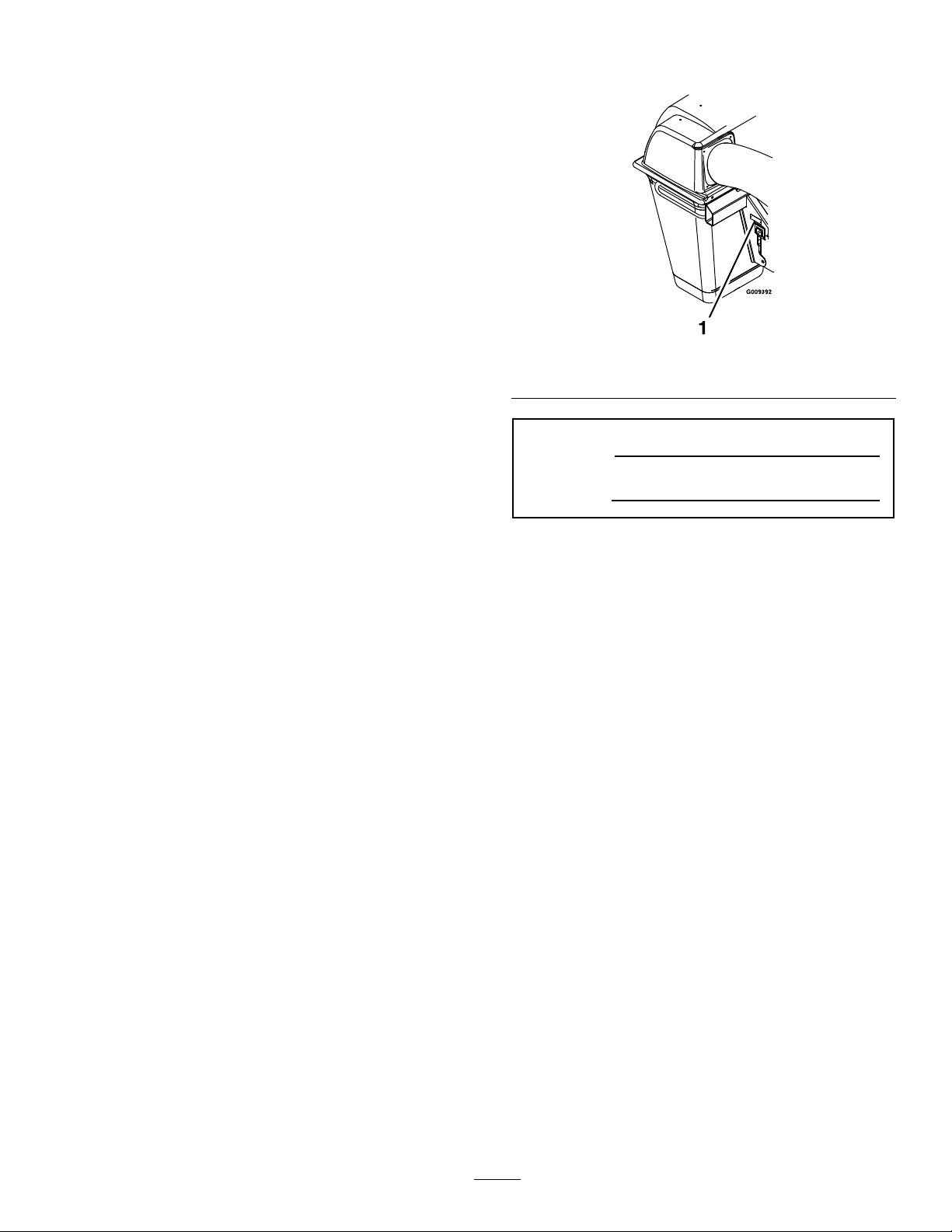
Figure1
1.Modelandserialnumberlocation
ModelNo.
SerialNo.
Wheneveryouneedservice,genuineExmarkparts,
oradditionalinformation,contactanAuthorized
ServiceDealerorExmarkCustomerServiceandhave
themodelandserialnumbersofyourproductready.
Figure1identiesthelocationofthemodelandserial
numbersontheproduct.Writethenumbersinthe
spaceprovided.
3
Page 4

Contents
Introduction...........................................................3
Safety.....................................................................5
SafetyAlertSymbol.........................................5
SafeOperatingPractices..................................5
SafetyandInstructionalDecals.......................8
Specications.......................................................10
ModelNumbers............................................10
Systems.........................................................10
Dimensions...................................................10
TorqueRequirements....................................11
ProductOverview................................................12
Operation.............................................................12
Pre-Start........................................................12
OperatingInstructions..................................12
Transporting.................................................16
Maintenance.........................................................18
RecommendedMaintenanceSchedule(s)...........18
PeriodicMaintenance.......................................18
CheckBlowerHousing/Impeller...................18
CheckBags....................................................18
LubricateGreaseFittings...............................19
CheckConditionofBelt................................19
Cleaning...........................................................20
CleanMuferandRearFrameArea................20
CleanRearScreenInHood............................20
CleanBlower.................................................20
Troubleshooting...................................................21
4
Page 5
Safety
Safety
SafetyAlertSymbol
ThisSafetyAlertSymbol(Figure2)isusedbothin
thismanualandonthemachinetoidentifyimportant
safetymessageswhichmustbefollowedtoavoid
accidents
Thissymbolmeans:ATTENTION!BECOME
ALERT!YOURSAFETYISINVOLVED!
Figure2
1.Safetyalertsymbol
Thesafetyalertsymbolappearsaboveinformation
whichalertsyoutounsafeactionsorsituations
andwillbefollowedbythewordDANGER,
WARNING,orCAUTION.
DANGER:Whitelettering/Redbackground.
Indicatesanimminentlyhazardoussituationwhich,if
notavoided,Willresultindeathorseriousinjury.
WARNING:Blacklettering/Orangebackground.
Indicatesapotentiallyhazardoussituationwhich,if
notavoided,Couldresultindeathorseriousinjury.
•Neverletchildrenoruntrainedpeopleoperate
orservicetheequipment.Localregulationsmay
restricttheageoftheoperator.
•Onlyadultsandmatureteenagersshouldoperate
amower,andevenmatureteenagersshouldhave
adultsupervision.Besureateenager:
1.hasreadandunderstandstheOperator’s
Manualandrecognizestherisksinvolved;
2.issufcientlymaturetousecaution;and
3.isofsufcientsizeandweighttooperate
thecontrolscomfortablyandtomanagethe
mowerwithouttakingrisks.
•Theowner/usercanpreventandisresponsible
foraccidentsorinjuriesoccurringtohimselfor
herself,otherpeopleorproperty.
Preparation
•Evaluatetheterraintodeterminewhataccessories
andattachmentsareneededtoproperlyandsafely
performthejob.Onlyuseonmachinesapproved
byExmark.
•Wearappropriateclothingincludingsafetyglasses,
substantialfootwear,longtrousers,andhearing
protection.DoNotoperatewhenbarefootor
whenwearingopensandals.
CAUTION:Blacklettering/Yellowbackground.
Indicatesapotentiallyhazardoussituationwhich,if
notavoided,Mayresultinminorormoderateinjury.
Thismanualusestwootherwordstohighlight
information.Importantcallsattentiontospecial
mechanicalinformationandNoteemphasizes
generalinformationworthyofspecialattention.
SafeOperatingPractices
Training
•ReadthetractorandUltraVacOperator’sManuals
andothertrainingmaterial.Iftheoperator(s)or
mechanic(s)cannotreadEnglishitistheowner’s
responsibilitytoexplainthismaterialtothem.
•Becomefamiliarwiththesafeoperationofthe
equipment,operatorcontrols,andsafetysigns.
•Alloperatorsandmechanicsshouldbetrained.
Theownerisresponsiblefortrainingtheusers.
CAUTION
Thismachineproducessoundlevelsin
excessof85dBAattheoperator’searand
cancausehearinglossthroughextended
periodsofexposure.
Wearhearingprotectionwhenoperatingthis
machine.
•Inspecttheareawheretheequipmentistobe
usedandremoveallrocks,toys,sticks,wires,
bones,andotherforeignobjectswhichcanbe
thrownbythemachineandmaycausepersonal
injurytotheoperatororbystanders.
Operation
•Operateonlyindaylightorgoodarticiallight,
keepingawayfromholesandhiddenhazards.
•Nevermowwiththedischargedeectorraised,
removedoralteredunlessthereisagrass
5
Page 6

Safety
collectionsystemormulchkitinplaceand
workingproperly.
DANGER
Therearerotatingbladesintheblowerand
underthemowerdeck.Bladecontactcan
causeseriousoperatororbystanderinjury
orevendeath.
•DoNotreachintoblowerunlessrotation
indicatorhasstopped.DisengagePTO,
stopengine,removekey,waitforall
movingpartstostop.engageparking
brake.
•Neveroperatemowerunlessdischarge
deector,entiregrasscollectionsystem,
ormulchkitisinstalled.
•Stopengine,waitforallmovingpartstostop,
removekeyandengageparkingbrake:
–Beforechecking,cleaningorworkingonthe
mower.
–Afterstrikingaforeignobjectorabnormal
vibrationoccurs(inspectthemowerfor
damageandmakerepairsbeforerestarting
andoperatingthemower).
–Beforeclearingblockages.
–Wheneveryouleavethemower.
WARNING
SlopeOperation
UseExtremecautionwhenmowingand/orturning
onslopesaslossoftractionand/ortip-overcould
occur.Theoperatorisresponsibleforsafeoperation
onslopes.
DANGER
Operatingonwetgrassorsteepslopescan
causeslidingandlossofcontrol.Wheels
droppingoveredges,ditches,steepbanks,or
watercancauserollovers,whichmayresult
inseriousinjury,deathordrowning.
•DoNotmowslopeswhengrassiswet.
•DoNotmowneardrop-offsornearwater.
•DoNotmowslopesgreaterthan15
degrees.
•Reducespeedanduseextremecaution
onslopes.
•Avoidsuddenturnsorrapidspeed
changes.
•Keeptherollbarintheraisedandlocked
positionanduseseatbelt.
•Seeinsidethebackcovertodeterminethe
approximateslopeangleoftheareatobemowed.
•Useawalkbehindmowerand/orahandtrimmer
neardrop-offs,ditches,steepbanksorwater.
(Figure3).
Hands,feet,hair,clothing,oraccessoriescan
becomeentangledinrotatingparts.Contact
withtherotatingpartscancausetraumatic
amputationorseverelacerations.
•DoNotoperatethemachinewithout
guards,shields,andsafetydevicesin
placeandworkingproperly.
•Keephands,feet,hair,jewelry,orclothing
awayfromrotatingparts.
•Stoptheblades,slowdown,andusecautionwhen
crossingsurfacesotherthangrassandwhen
transportingthemowertoandfromtheareato
bemowed.
•Beawareofthemowerdischargepathanddirect
dischargeawayfromothers.
6
Page 7

progressivelygreatercareonslopesasthehopper
lls.
MaintenanceandStorage
•Disengagedrives,setparkingbrake,stopengine
andremovekeyordisconnectsparkplugwire.
Waitforallmovementtostopbeforeadjusting,
cleaningorrepairing.
•Usecarewhencheckingblades.Wraptheblade(s)
orweargloves,andusecautionwhenservicing
them.Onlyreplacedamagedblades.Never
straightenorweldthem.
Safety
Figure3
1.SafeZone-Usethemowerhereonslopeslessthan15
degrees
2.DangerZone-Useawalkbehindmowerand/orhand
trimmeronslopesgreaterthan15degrees,near
drop-offsandwater.
3.Water
•Removeormarkobstaclessuchasrocks,tree
limbs,etc.fromthemowingarea.Tallgrasscan
hideobstacles.
•Watchforditches,holes,rocks,dipsandrisesthat
changetheoperatingangle,asroughterraincould
overturnthemachine.
•Avoidsuddenstartswhenmowinguphillbecause
themowermaytipbackwards.
•Beawarethatoperatingonwetgrass,acrosssteep
slopesordownhillmaycausethemowertolose
traction.Lossoftractiontothedrivewheelsmay
resultinslidingandalossofbrakingandsteering.
•Alwaysavoidsuddenstartingorstoppingona
slope.Iftireslosetraction,disengagetheblades
andproceedslowlyofftheslope.
•Keepallguards,shieldsandallsafetydevicesin
placeandinsafeworkingcondition.
•Checkallboltsfrequentlytomaintainproper
tightness.
•Frequentlycheckforwornordeteriorating
componentsthatcouldcreateahazard.
•Allreplacementpartsmustbethesameas
orequivalenttothepartssuppliedasoriginal
equipment.
•Followthemanufacturer’srecommendationsfor
wheelweightsorcounterweightstoimprove
stability.AlwaysinstallandremovetheUltraVac,
includingcounterweights,asinstructed.Failure
todosowillcauseareductioninstabilityor
traction.DoNotoperatethemowerwithonlya
portionoftheUltraVacinstalled.
•Useextremecarewithgrasscatchersor
attachments.Thesecanchangethestabilityofthe
machineandcauselossofcontrol.Thestability
andtractionofthemachinewillchangeasthe
UltraVachopperllswithgrassclippings.Use
7
Page 8
Safety
SafetyandInstructionalDecals
•Keepallsafetysignslegible.Removeallgrease,
dirtanddebrisfromsafetysignsandinstructional
labels.
•Replaceallworn,damaged,ormissingsafety
signs.
•Whenreplacementcomponentsareinstalled,be
surethatcurrentsafetysignsareafxedtothe
replacedcomponents.
•Ifanattachmentoraccessoryhasbeeninstalled,
makesurecurrentsafetysignsarevisible.
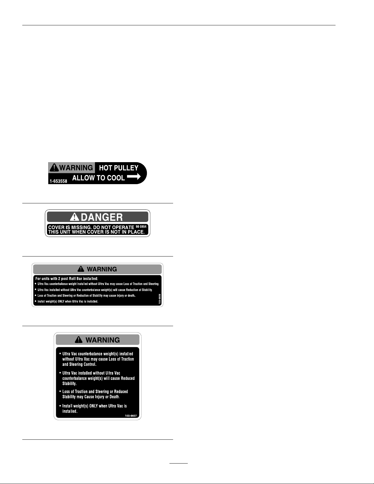
1-653558
•Newsafetysignsmaybeobtainedfrom
yourauthorizedExmarkequipmentdealeror
distributororfromExmarkMfg.Co.Inc.
•Safetysignsmaybeafxedbypeelingoffthe
backingtoexposetheadhesivesurface.Apply
onlytoaclean,drysurface.Smoothtoremove
anyairbubbles.
•Familiarizeyourselfwiththefollowingsafetysigns
andinstructionlabels.Theyarecriticaltothesafe
operationofyourExmarkcommercialmower.
98-5954
103-6606
103-6607
8
Page 9

103-3508
LZUV52Only
Safety
UV60andUV6672
109-5890
9
Page 10

Specications
Specications
ModelNumbers
SerialNos:850,000andHigher
LZUV52–FitsLazerZ(LZ)andLazerZAS(LAS)Units789,999andLowerwith52inchdeck.
UV60–FitsLazerZ(LZ),LazerZAS(LAS),andLazerZXPUnits352,000–789,999andLazerZXSUnits352,000
andHigherwith60inchdeck.
UV6672–LazerZ(LZ),LazerZAS(LAS),andLazerZXPUnits352,000–789,999andLazerZXSUnits352,000
andHigherwith66inchor72inchdeck.
Systems
BaggingSystem
•Collectionbins:
–Commercialgrade,clothmeshbagswith
reinforcedbottoms.
–Capacity:11.0bushels
52inchdecks:8bushels(2bagsandhood)
60,66,and72inchdecks:13.4bushels(3
bagsandhood)
•DumpMechanism:Manualliftoff
•BlowerTube:Fixed,abrasionresistantmolded
polyethylene.
•Impeller:5–bladed,1/4inch(6.4mm)thick
abrasionresistantsteel,withverticalaxis.
•Impellerbearings:1inch(2.5cm)sealed
non-greaseablebearings.
72inchDeck-SN599,999
andLower
72inchDeck-SN600,000
andHigher
w/UltraVac
86.49inches(219.7cm)
87.38inches(221.9cm)
Dimensions
OverallWidth:
52inchDeck-All
60inchDeck-SN599,999
andLower&AllLazerAS
789,999andLower
60inchDeck-SN600,000
andHigher
66inchDeck-All
w/UltraVac
66.85inches(169.8cm)
74.44inches(189.1cm)
74.94inches(190.3cm)
81.50inches(207.0cm)
10
Page 11

Specications
OverallLength:
52inchDeck-Air-Cooled
52inchDeckLiquid-Cooled
60inchDeck-SN599,999
andLowerAir-Cooled
60inchDeck-SN
600,000–789,999
Air-Cooled
60inchDeck-SN599,999
andLowerLiquid-Cooled
60inchDeck-SN599,999
andLowerLazerXP&XS
60inchDeck-SN600,000
andHigherLazerXP&XS
66inchDeck-Air-Cooled
66inchDeck-LazerXP&
XS
72inchDeck-SN599,999
andLowerAir-Cooled
w/UltraVac
105.70inches(268.5cm)
106.00inches(269.1cm)
106.65inches(270.9cm)
110.04inches(279.5cm)
106.90inches(271.5cm)
107.90inches(274.1cm)
110.88inches(281.6cm)
111.59inches(283.4cm)
112.43inches(285.6cm)
110.75inches(281.3cm)
CurbWeight:
w/UltraVac
52inchDeck-All254lb(115kg)
60inchDeck-SN599,999
andLower&AllLazerAS
789,999andLower
60inchDeck-SN600,000
andHigherAir-Cooled
(exceptAS)
60inchDeck-SN600,000
andHigherLiquid-Cooled
66inchDeck-All
Air-Cooled
66inchDeck-All
Liquid-Cooled
72inchDeck-SN600,000
andHigher
72inchDeck-SN600,000
andHigherAir-Cooled
72inchDeck-SN600,000
andHigherLiquid-Cooled
324lb(147kg)
243lb(110kg)
261lb(118kg)
190lb(86kg)
208lb(94kg)
271lb(123kg)
190lb(86kg)
208lb(94kg)
72inchDeck-SN
600,000–789,999
Air-Cooled
72inchDeck-SN599,999
andLowerLiquid-Cooled
72inchDeck-SN599,999
andLowerLazerXP&XS
72inchDeck-SN600,000
andHigherLazerXP&XS
114.12inches(289.9cm)
111.00inches(278.3cm)
112.00inches(281.9cm)
115.37inches(293.0cm)
TorqueRequirements
BoltLocation
ImpellerSpindleBottom
Nut
ImpellerSpindleTopNut75-80ft-lb(102-108N-m)
Torque
55-60ft-lb(75-81N-m)
11
Page 12

Operation
ProductOverview
Figure4
1.Hood4.Tube
2.Weight5.Bag
3.Blower
Operation
Note:Determinetheleftandrightsidesofthe
machinefromthenormaloperatingposition.
Pre-Start
Makesureyouunderstandthecontrols,their
locations,theirfunctions,andtheirsafety
requirements.
Ensuretheblower,beltcover,bags,tubeandhood
areingoodcondition,properlyattached,andlatched.
ForunitsaboveSerialNumber600,000withTriton
decks:Makesurethattheadjustabledoglegbafeis
closedtomatchtheintakeintotheUltraVacBlower.
WARNING
Ifthedeckdischargeopeningandtheblower
intakeopeningdonotmatchcorrectly,it
willallowobjectstobethrowninoperator’s
orbystander’sdirection.Also,contactwith
bladecouldoccur.Thrownobjectsorblade
contactcancauseseriousinjuryorkillyou
orbystanders.
Adjustdoglegbafetomatchintake
opening.
RefertotheMaintenancesectionandperformallthe
necessaryinspectionandmaintenancesteps.
OperatingInstructions
Mowing
1.TheUltraVacbloweroperateswhendeckdrive
isengaged.Besurethatallpersonsareclear
ofthemowerdeckbeforeengagingthecutting
blades.Setthethrottleto“midway”position.Pull
outwardonthePTOswitchtothe“ROTATE”
position.Acceleratetofullthrottletobegin
mowing.
2.Todisengagethedeckdriveandblower,setthe
throttleto“midway”position.Pushinonthe
PTOswitchtothe“STOP”positiontostopthe
cuttingbladesandblower.Thecuttingbladeswill
requireaslightlylongeramountoftimetocome
toacompletestopwhentheblowerisinstalled
onthedeck.Verifythatallrotationindicators
12
Page 13

havestoppedbeforeclearingblowerassemblyor
mowerdeck
3.Toremovethebags,rstshutoffdeckdrive,stop
theengineandwaitforallmovingpartstostop.
Openthehoodandremovethebagsbyliftingup
ontherearofthebag,thenunhookingthefront
clip.Emptythebagsbyinvertingthem.
4.Reinstallbags,closeandlatchhoodbefore
continuingmowing.
Tipsformowingconditions:
•Whenmowinginareaswithsandysoil,use
lowliftbladesonthecuttingdeckandhigher
cuttingheightstominimizewearontheblower
components.
•Whenmowinginwetconditions,suchasjustafter
arainorinheavydew ,uselowliftbladesonthe
cuttingdecktominimizepluggingoftheblower.
•Maintainingagroundspeedthatdoesnotpull
downtheengineRPMwillallowforthehighest
productivityandbestqualityofcut.Boggingthe
engineRPMdownbygoingtoofastwillcause
pluggingandqualityofcutissues.
Figure5
1.ClevisPin5.BeltCover
2.CasterArmWeight
3.Hairpin7.Tube
4.FrontFloorpanWeight8.Bags
6.Blower
Operation
•Whenthebagsgetfull,thesoundoftheblower
willchangeandtherewillbeslightblowoutfrom
thefrontrightcornerofthedeck.Emptyingthe
bagsatthispointwillminimizethepotentialfor
thetubetoplug.
•ForunitsbelowSerialNumber600,000:
Anti-blowoutkitsareavailableforleafcollection.
Theyhelptoprevent“chasing”theleaves.To
reduce“plowing”leaves,raisethedeckslightly.
•OnTriton:Raisefrontadjustablebafeto
reduceplowing.Loweringfrontadjustablebafe
mayprevent“chasing”.Matchdischargeopening
toUltraVacintakeforbestperformance.
BaggerRemovalforSideDischarge
1.Shutoffthedeckdrive,stopengineandwaitfor
allmovingpartstostop.Removekeyandengage
parkingbrake.
2.Removethedischargetubebyreleasingthe
latchesattheblower.Slidethetubeofftheblower
outletandremovetheupperendfromthehood.
3.Removethebeltcoverbylooseningtheknobs.
For60inchand66inchunitstheoutboardknob
doesnotneedtoberemovedcompletelyto
removethebeltcover.
CAUTION
Thedecksheavewillbecomeveryhot.
Touchingahotdecksheavecancausesevere
burns.
Allowthedecksheavetocoolcompletely
beforeremovingthebelt.
4.Pulltheidlerreleasehandleandremovethebelt
fromtheuppergrooveofthedecksheave.
5.Unlatchthefrontendoftheblower.Pivotthe
blowerbackandliftitoffthedeck.
6.Installthedischargechuteusingthechutepivot
pinandhairpin(seeFigure6).
13
Page 14

Operation
Note:Theremovableweightsareheavy.Use
carewhenliftingthem.Makesurethatyoucan
holdthemsecurelybeforeliftingthem.Use
cautionwhenpositioningyourhandssothatyou
DoNotsetthemdownonyourhandsorngers.
Note:TheportionsoftheUltraVacbaggerthat
arenotboltedtothemoweraredesignedtobe
installedorremovedintheirentirety.Failureto
dosowillcauseareductioninstabilityortraction.
DoNotoperatethemowerwithonlyaportion
Figure6
Viewedfromtherightside
oftheUltraVacinstalled.
1.Hairpin
2.ChutePivotPin
Note:Installchutewiththetabstotherearof
thedecktabsasshown.
3.DischargeChute
WARNING
Anuncovereddischargeopeningwill
allowobjectstobethrowninoperator’sor
bystander’sdirection.Also,contactwith
bladecouldoccur.Thrownobjectsorblade
contactcancauseseriousinjuryorkillyou
orbystanders.
Neveroperatemowerunlessdischarge
deector,orentiregrasscollectionsystem,or
mulchkitisinstalled.
7.Re-installtheplasticbeltcoverandtightenthe
knobs.
8.Removethehairpinsandclevispinsholdingthe
hoodassemblytothemountweldment.
9.Liftthehoodassemblyoffthemount.
10.Theremovableweightsmustberemovedfrom
abovethecasterwheels(andfrontofoorpan
onsomeunits).Toremovethecasterweights.
Loosentheclampingknobsuntiltheweightcan
bemovedrelativetothecasterarm.Removethe
hairpinsandclevispinsthatholdtheweightsto
thecasterarms.Carefullylifttheweightsoffof
thecasterarms.
Toremovetheweightonthefrontoftheoor
pan,removethetwohairpinsthatretainitand
thenliftitfromthemountplates.
Theweightsandbracketsboltedtotheoorpan
remainontheunit.
CAUTION
Casterorfrontoorpanweightsinstalled
withoutbaggermaycauselossoftraction
andsteeringcontrol.Lossofcontrolcan
resultinanaccident,whichmaycausedeath,
injury,orpropertydamage.
Installcasterorfrontoorpanweights
ONLYwhenbaggerisinstalled.
11.Themachinecannowbeusedforsidedischarge
mowing.
BaggerInstallationforBagging
1.Stopengine,removekey,andwaitforallmoving
partstostop.Engageparkingbrake.
2.Removehairpinandchutepivotpin.Remove
dischargechute.Pivotpinandhairpinmaybe
storedinthepivotholesofthedischargechute
duringbaggingoperation.
3.Installthebaggerassemblyontothemountby
slippingthehookportionoverthetopmounting
tubeofthemountweldment(seeFigure5).
Securetheassemblytothemountusingtheclevis
pinsandhairpins.
4.Installthebagassembliesbyinsertingthehook
portionintotheslotsinthecrossbarofthehood
assembly.
5.Mountthebloweronthedeckbyslidingthe
mountingpinintothetubeattherearrightcorner
ofthedeck.Swingtheblowerclosed.Adjustthe
positionofthefrontpintoengagetheslotinthe
frontofthedeck.Usethelatchtolocktheblower
inthisposition.Adjustthetensiononthelatch
toholdthebloweruptothedeck,yetallowfor
releasebyhand.
14
Page 15

6.Pullthespringloadedidlerbackandslipthebelt
overthetopspindledecksheave.
7.Installtheplasticbeltcover.On60inchand66
inchunitstheoutsideendofthecoverisslotted
andcanslipbetweenthetwowashersonthebelt
shieldstud.Theplasticknobdoesnotneedto
beremoved.On72inchand52inchunitsthe
coverhasahole,andtheplasticknobmustbe
installedafterthecoverhasbeenpositioned.The
originalbeltcoverstudmustberemovedon
52inchunits.
8.ForUnitsSerialNumber600,000andHigher
withTritonDecks:Adjustpositionofdogleg
bafetomatchtheintakeoftheUltraVacblower
bafeadjustedtoowidemayallowobjectstobe
thrownfromunderdeck.Bafeadjustedtoo
narrowmaycausepluggingissues.
1.ClevisPin
Operation
Figure7
2.Hairpin
AllUnits:Sliptheupperendofthetube
assemblyintothehoodopening.Slidethelower
endofthetubeassemblyoverthebloweroutlet
andalignthenotchwiththetubelatch.Latchthe
tubetotheblower.
Note:Theremovableweightsareheavy.Use
carewhenlifting.Makesurethatyoucanholdthe
weightsecurelybeforelifting.Usecautionwhen
positioningyourhandssothatyouDoNotset
theweightdownonyourhandsorngers.
9.Installtheremovableweightassembliesover
thecasterarms.On52inchand60inchLazer
ZASmachinesand60inchLazerZmachines
serialnumber599,999andlower,oneweighthas
awidemountingbracketandonehasanarrow
bracket.Theywillonlytthemachineoneway.
Weightsforthe60inchLazerZserialnumber
600,000andhigher,60inchLazerZXP ,60inch
LazerZXSandall66inchand72inchunitsare
interchangeableleftandright.
10.Installaclevispinandhairpinoneachcaster
weighttoretainthem(seeFigure7).
11.Unitswithremovableoorpanweight:
Tightenknobonweightassemblyuntiltheweight
isclampedsecurelytothecasterarm.
12.Hookweightplateassemblyoverthetopofthe
weightmountingplatesandsecurewithtwo
hairpinsasshowninFigure8).
Figure8
1.WeightPlateAssembly2.Hairpin
Note:TheportionsoftheUltraVacbaggerthat
arenotboltedtothemoweraredesignedtobe
installedorremovedintheirentirety.DoNot
operatethemowerwithonlyaportionofthe
UltraVacinstalled.
15
Page 16

Operation
Transporting
TransportingaUnit
Useaheavy-dutytrailerortrucktotransportthe
machine.Lockbrakeandblockwheels.Securely
fastenthemachinetothetrailerortruckwithstraps,
chains,cable,orropes.Besurethatthetrailerortruck
hasallnecessarylightingandmarkingasrequiredby
law .Secureatrailerwithasafetychain.
CAUTION
Thisunitdoesnothaveproperturn
signals,lights,reectivemarkings,ora
slowmovingvehicleemblem.Drivingona
streetorroadwaywithoutsuchequipment
isdangerousandcanleadtoaccidents
causingpersonalinjury.Drivingonastreet
orroadwaywithoutsuchequipmentmayalso
beaviolationofStatelawsandtheoperator
maybesubjecttotrafcticketsand/ornes.
DoNotdriveaunitonapublicstreetor
roadway.
WARNING
Loadingaunitonatrailerortruckincreases
thepossibilityofbackwardtip-over.
Backwardtip-overcouldcauseseriousinjury
ordeath.
•Useextremecautionwhenoperatinga
unitonaramp.
•Useonlyasingle,fullwidthramp;Do
Notuseindividualrampsforeachside
oftheunit.
•Ifindividualrampsmustbeused,use
enoughrampstocreateanunbroken
rampsurfacewiderthantheunit.
•DoNotexceeda15°anglebetweenramp
andgroundorbetweenrampandtrailer
ortruck.
•Avoidsuddenaccelerationwhiledriving
unituparamptoavoidtippingbackward.
•Avoidsuddendecelerationwhilebacking
unitdownaramptoavoidtipping
backward.
LoadingaUnit
Emptygrassbagsbeforeattemptingtoload
unitontrailerortruck.Useextremecautionwhen
loadingunitsontrailersortrucks.Onefullwidth
rampthatiswideenoughtoextendbeyondtherear
tiresisrecommendedinsteadofindividualrampsfor
eachsideoftheunit.Thelowerrearsectionofthe
tractorframeextendsbackbetweentherearwheels
andservesasastopfortippingbackward.Having
afullwidthrampprovidesasurfacefortheframe
memberstocontactiftheunitstartstotipbackward.
Ifitisnotpossibletouseonefullwidthramp,use
enoughindividualrampstosimulateafullwidth
continuousramp.
Rampshouldbelongenoughsothattheangles
betweentherampandthegroundandtherampand
thetrailerortruckDoNotexceed15°.Asteeper
anglemaycausemowerdeckcomponentstoget
caughtastheunitmovesfromramptotraileror
truck.Steeperanglesmayalsocausetheunittotip
backward.Ifloadingonornearaslope,position
thetrailerortrucksoitisonthedownsideofthe
slopeandtherampextendsuptheslope.Thiswill
16
Page 17

minimizetherampangle.Thetrailerortruckshould
beaslevelaspossible.
Important:DoNotattempttoturntheunit
whileontheramp,youmaylosecontroland
driveofftheside.
Avoidsuddenaccelerationwhendrivinguparamp
andsuddendecelerationwhenbackingdownaramp.
Bothmaneuverscancausetheunittotipbackward.
Operation
17
Page 18

Maintenance
Maintenance
Note:Determinetheleftandrightsidesofthemachinefromthenormaloperatingposition.
WARNING
Whilemaintenanceoradjustmentsarebeing
made,someonecouldstarttheengine.
Accidentalstartingoftheenginecould
seriouslyinjureyouorotherbystanders.
Removethekeyfromtheignitionswitch,
engageparkingbrake,andpullthewire(s)
offthesparkplug(s)beforeyoudoany
maintenance.Alsopushthewire(s)aside
soitdoesnotaccidentallycontactthespark
plug(s).
RecommendedMaintenanceSchedule(s)
MaintenanceService
Interval
Beforeeachuseordaily
MaintenanceProcedure
•Checktheblowerhousing/impeller.
•Checkbags.
•Cleanmuferandrearframearea.
•Cleanrearscreeninthehood.
WARNING
Theenginecanbecomeveryhot.T ouching
ahotenginecancausesevereburns.
Allowtheenginetocoolcompletelybefore
serviceormakingrepairsaroundtheengine
area.
Every25hours
Every50hours
Yearlyorbeforestorage
•Lubricategreasettings.
•Checkconditionofbelt.
•Cleanblower.
PeriodicMaintenance
CheckBlower
Housing/Impeller
ServiceInterval:Beforeeachuseordaily
1.Stopengine,waitforallmovingpartstostop,and
removekey .Engageparkingbrake.
2.Inspectforwearordamagedaily.Replaceor
repairwornpartsasneeded
Note:Whenmowinginareaswithsandysoil,
uselowliftbladesonthecuttingdeckandhigher
cuttingheightstominimizewearontheblower
components.
CheckBags
ServiceInterval:Beforeeachuseordaily
1.Stopengine,waitforallmovingpartstostop,and
removekey .Engageparkingbrake.
2.Inspectthebagsforwear,tears,ordamage.
WARNING
Undernormalusethebagwilldeteriorate
andwear.Objectscouldexitthroughworn
bagathighspeeds.Thrownobjectscan
causeseriousinjuryorkillyouorbystanders.
Checkbagsfrequentlyfortearsandholes.
Replacewornbags.
18
Page 19

LubricateGreaseFittings
Note:Seechartforserviceintervals.
1.Stopengine,waitforallmovingpartstostop,and
removekey .Engageparkingbrake.
2.LubricatettingswithNGLIgrade#2
multi-purposegungrease.
Refertothefollowingchartforttinglocations
andlubricationschedule.
LubricationChart
Fitting
Locations
1.Idler
Bushings
Initial
Pumps
1–21
Numberof
Places
Service
Interval
25Hours
CheckConditionofBelt
ServiceInterval:Every50hours
AllUnits
1.Stopengine,waitforallmovingpartstostop,and
removekey .Engageparkingbrake.
2.Inspectthebeltfordamageorwear.Replacebelt
withoneofthefollowing:
Deck
52inch–All
60inchLazerZ,XS,XP
SN599,999andLowerand
AllLazerAS
72inchAllSN599,999
andLower
60inchTriton
66inchTriton
72inchTriton
PartNo.
1–653438
103-0866
103-0867
109-1242
103-0867
109-1244
Maintenance
Figure9
ViewFromT opofBlower
1.Springloadedidler
2.Impellersheave
3.Fixedidler
3.Removetheoldbelt.
4.Installthenewbeltontotheblowerassemblyas
showninFigure9.
5.Reinstallthebeltguideremovedinstep2.
6.Reinstalltheblowerontothedeck.
For52inchUnitsOnly-InspectBeltPositionon
theIdlerArm:
Theidlerarmmaybecomebentduringuseor
transport.Abentidlerarmcouldcausethebeltto
jumpoffoftheidlerandbedamaged.
1.Makesurethebeltcoverisinstalledandrunthe
blowerforonetotwominutes.
2.Shutoffthedeckdrive,stopengine,wait
forallmovingpartstostopandremovekey.
Engageparkingbrake.Removethebeltcover
andchecktomakesurethatthebeltisridingnear
thecenteroftheatidlerontheidlerarm.
3.Ifthebeltisnotridingnearthecenterofthe
idler,removetheblower,andbendtheidlerarm
slightly.
4.Beltguide
5.Decksheave(reference)
For52inchUnitsOnly-BeltReplacement
Procedure:
1.Removetheblowerfromthedeck.
2.Removethebeltguideontheblower(see
Figure9).
4.Reinstalltheblowerandbeltcoverandrepeat
steps1through3untilthebeltispositionednear
thecenteroftheidler.
19
Page 20

Maintenance
Cleaning
CleanMuferandRear
FrameArea
ServiceInterval:Beforeeachuseordaily
Stopengine,waitforallmovingpartstostop,and
removekey .Engageparkingbrake.
WARNING
Operatingengineparts,especiallythe
mufer,becomeextremelyhot.Severeburns
canoccuroncontactanddebris,suchas
leaves,grass,brush,etc.cancatchre.
•Allowengineparts,especiallythemufer,
tocoolbeforetouching.
•Removeaccumulateddebrisfrommufer
andenginearea.
•Installandmaintaininworkingordera
sparkarresterbeforeusingequipment
onforest-covered,grass-covered,
brush-coveredunimprovedland.
CleanRearScreenInHood
ServiceInterval:Beforeeachuseordaily
1.Stopengine,waitforallmovingpartstostop,and
removekey .Engageparkingbrake.
2.Openhoodandremoveclippingsthatarestuck
tothescreen.
CleanBlower
ServiceInterval:Yearlyorbeforestorage
Grassbuildupmaycauseproblemswiththeimpeller
whentheunitisputbackintooperation.
1.Stopengine,waitforallmovingpartstostop,and
removekey .Engageparkingbrake.
2.Removegrassbuildupfromaroundtheimpeller
beforeplacingitinstorage.
20
Page 21

Troubleshooting
Troubleshooting
Important:Itisessentialthatalloperatorsafetymechanismsbeconnectedandinproperoperating
conditionpriortomoweruse.
Whenaproblemoccurs,DoNotoverlookthesimplecauses.Forexample:startingproblemscouldbe
causedbyanemptyfueltank.
Thefollowingtablelistssomeofthecommoncausesoftrouble.DoNotattempttoserviceorreplacemajor
itemsoranyitemsthatcallforspecialtimingoradjustmentprocedures(suchasvalves,governor,etc.).Have
thisworkdonebyyourEngineServiceDealer.
Note:WhendisconnectingelectricalconnectorsDoNotpullonthewirestoseparatetheconnectors.
ProblemPossibleCauseCorrectiveAction
Abnormalvibration.
Blowerdrivebeltsnapsorbreaksfrequently.
Excessivegrassblowoutfromthedeck.
Blowerandtubesplugtoofrequently.
Blowerimpellerdoesnotspinfreely.
1.Cuttingblade(s)is/arebentorunbalanced.
2.Blademountingboltisloose.2.Tightentheblademountingbolt.
3.Looseblowerpulleyorpulleyassembly.
4.Blowerimpellerbladesarebent.4.ContactanAuthorizedServiceDealer.
1.Idlerarmisoutofalignment.1.Correctthealignmentoftheidlerarm.
1.Bagsarefull.
2.Pluggedscreeninbaggerhood.2.Removedebris,leavesorgrassclippings
3.Groundspeedistoofast.
4.Blowerbeltisworn,loose,orbroken.4.Installnewblowerbelt.
5.Pluggedtubeorblower.5.Locateandremovepluggeddebris.
6.Conditionsaredry.6.Uselowerliftblade.
1.Bagsaretoofull.
2.Groundspeedistoofast.
3.Grassistoowet.
4.Grassistoolong.4.Cutgrassmorefrequentlyorathighercut
5.Pluggedscreeninbaggerhood.5.Removedebris,leaves,orgrassclippings
6.Blowerdrivebeltisworn,loose,or
broken.
7.Blowerisplugged.7.Uselowliftbladesinwetconditions.
1.Pluggedblower.1.Removedebris,leaves,orgrassclippings
2.Impellernotaligned.2.ContactanAuthorizedServiceDealer.
1.Installnewcuttingblade(s).
3.Tightentheappropriatepulley.
1.Emptybagsmorefrequently.
fromthescreen.
3.Drivesloweratfullthrottle.
1.Emptybagsmorefrequently
2.Drivesloweratfullthrottle.
3.Cutgrasswhenitisdry.
height.
fromthescreen.
6.Installnewbelt.
fromtheblowerimpeller.
Plowingleaves.
Chasingleaves.
Blowercomponentsshowsignsofwear
and/oraircleanersandcoolingnsaredirty.
1.Deckistoolow.
1.Blowoutfromdeck.
1.Sandordryconditions.1.Uselowliftbladesonthecutting
1.
UnitsbelowSerialNumber
600,000:Raisethedeckslightly.
Triton:Raisethefrontadjustablebafe.
1.
UnitsbelowSerialNumber600,000:
Installananti-blowoutkit–contact
anAuthorizedServiceDealer.
Triton:Lowerthefrontadjustable
bafe.MatchdischargeopeningtoUltra
Vacintake.
deckandhighercuttingheights.
Cleanaircleanersandcoolingns
frequently.
21
Page 22

Conditions and Products Covered
Exmark Mfg. Co. Inc. and its affiliate, Exmark Warranty
Company, pursuant to an agreement between them, jointly
warrant on the terms and conditions herein, that we will repair,
replace or adjust any part on these products and found by us
(in the exercise of our reasonable discretion) to be defective in
factory materials or workmanship for a period of one year.
This warranty applies to Exmark commercial attachments and
accessories sold in the U.S. or Canada. This warranty may
only be assigned or transferred to a second (or third) owner by
an authorized Exmark dealer. The warranty period commences
upon the date of the original retail purchase.
Warranty Exceptions Warranty Period
• Bags, Belts and Tires 90 days
This warranty only includes the cost of parts and labor.
Items and Conditions Not Covered
This warranty does not cover the following:
• Pickup and delivery charges to and from any authorized
Exmark Service Dealer.
• Any damage or deterioration due to normal use, wear and
tear, or exposure.
• Cost of regular maintenance service or parts, such as filters,
fuel, lubricants, tune-up parts, and adjustments.
• Any product or part which has been altered or misused or
required replacement or repair due to normal wear,
accidents, or lack of proper maintenance.
• Any repairs necessary due to use of parts, accessories or
supplies, including gasoline, oil or lubricants, incompatible
with the attachment or accessory or other than as
recommended in the operator's manual or other operational
instructions provided by Exmark.
All warranty work must be performed by an authorized
Exmark Service Dealer using Exmark approved replacement
parts.
Instructions for Obtaining Warranty Service
The product must be registered with original proof of purchase
by an Exmark Service Dealer before obtaining any warranty
service.
Contact any Exmark Service Dealer to arrange service at their
dealership. To locate a dealer convenient to you, access our
website at www.exmark.com. U.S. or Canada customers may
also call 402-223-6375.
If for any reason you are dissatisfied with the Service Dealer’s
analysis or with the assistance provided, contact us at:
Exmark Customer Service Department
The Exmark Warranty Company
2101 Ashland Avenue
Beatrice, NE 68310
402-223-6375 or
service@exmark.com
Owner’s Responsibilities
If your product requires warranty service it must be returned
to an authorized Exmark service dealer within the warranty
period. This warranty extends only to commercial attachments
and accessories operated under normal conditions. You must
read the operator’s manual. You must also properly service
and maintain your Exmark product as described in the
operator’s manual or other operational instructions provided
by Exmark. Such routine maintenance, whether performed by
a dealer or by you, is at your expense.
General Conditions
The sole liability of Exmark and Exmark Warranty Company
with respect to this warranty shall be repair or replacement of
defective components as set forth herein. Neither Exmark
nor Exmark Warranty Company shall be liable for any
incidental or consequential loss or damage.
Such damages include but are not limited to:
• Expenses related to gasoline, oil or lubricants.
• Travel time, overtime, after hours time or other
extraordinary repair charges or charges relating to repairs or
replacements outside of normal business hours at the place
of business of the authorized Exmark Service Dealer.
• Rental of like or similar replacement equipment during the
period of any warranty, repair or replacement work.
• Any telephone or telegram charges or travel charges.
• Loss or damage to person or property other than that
covered by the terms of this warranty.
• Any claims for lost revenue, lost profit or additional cost as
a result of a claim of breach of warranty.
• Attorney's fees.
No Claim of breach of warranty shall be cause for cancellation
or rescission of the contract of sale of any Exmark attachment
or accessory.
All implied warranties of merchantability (that the
product is fit for ordinary use) and fitness for use (that the
product is fit for a particular purpose) are limited to the
duration of the express warranty.
Some states do not allow exclusions of incidental or
consequential damages, or limitations on how long an
implied warranty lasts, so the above exclusions and
limitations may not apply to you.
This warranty gives you specific legal rights, and you may
also have other rights which vary from state to state.
Exmark Commercial
Attachments and Accessories
1 Year Limited Warranty
G4500-433_B
22
Page 23

G011841
Figure10
Thispagemaybecopiedforpersonaluse.
1.Themaximumslopeyoucansafelyoperatethemachineonis15degrees.Usetheslopeindicatortodeterminethe
degreeofslopeofhillsbeforeoperating.DoNotoperatethismachineonaslopegreaterthan15degrees.Fold
alongtheappropriatelinetomatchtherecommendedslope.
2.Alignthisedgewithaverticalsurface,atree,building,fencepole,etc.
3.Exampleofhowtocompareslopewithfoldededge.
23
Page 24

MI D-MO UNT RIDI NG ACCESSORIES AND OPTION S
SEE EXMARK’S COMPLETE LINE OF ACCESSORIES AND OPTIONS
WALK-BEHIND ACCESSORIES AND OPTIONS
GRASS CATCHER
MICRO-MULCH SYSTEM
TURF STRIPER
STANDON
CUSTOM RIDE SEAT SUSPENSION SYSTEM
FULL SUSPENSION SEAT
DECK LIFT ASSIST KIT
HITCH KIT
LIGHT KIT
12
V POWER PORT
MICRO-MULCH SYSTEM
OPERATOR CONTROLLED DISCHARGE
ROLL OVER PROTECTION SYSTEM (ROPS)
SUN SHADE
TRASH CONTAINER
TURF STRIPER
ULTRA VAC COLLECTION SYSTEM
ULTRA VAC QUICK DISPOSAL SYSTEM
OU T-FRONT RIDING AC CESS ORIE S AN D OP TION S
CUSTOM RIDE SEAT SUSPENSION SYSTEM
DUAL-TAIL WHEEL
FLOOR PAN EXTENDER
HITCH KIT
LIGHT KIT
MICRO-MULCH SYSTEM
ROLL OVER PROTECTION SYSTEM (ROPS)
SNOW BLADE
SNOWBLOWER
SUN SHADE
TRASH CONTAINER
ULTRA VAC COLLECTION SYSTEM
ULTRA VAC QUICK DISPOSAL SYSTEM
WEATHER CAB
PlaceModelNo.andSerialNo.
LabelHere(IncludedintheLiterature
Pack)orFillinBelow
ModelNo.
SerialNo.
©2009ExmarkMfg.Co.,Inc.
IndustrialParkBox808
Beatrice,NE68310
AllRightsReserved
DatePurchased
PartNo.4500-610Rev.A
(402)223-6300
Fax(402)223-5489
PrintedintheUSA
www.exmark.com
 Loading...