

Page 1

c
For Exmark Mower Parts Call 606-678-9623 or 606-561-4983
For Serial Nos.
670,000 & Higher
®
MFG. CO. INC.
®
on the purchase of your new Exmark mower. This product has been carefully designed and manufactured to give you a
maximum amount of dependability and years of trouble-free operation. If additional information is needed, or should you require trained mechani
service, contact your authorized Exmark equipment dealer or distribu tor. If you need to order replacement parts from your dealer, always give the
model number and serial number of your mower as well as the part number, description and quantity of the part needed.
The Serial No. plate is located on the right side of the console. For ease of ordering and reference, we suggest that you record the information
requested in the following identification table.
Place Model No. and Serial No. Label Here
(Included in Literature Pack)
or Fill in Below
Engine Model No. and Spec. No. (Code)
Engine Serial No. (E/No)
Model No.
Date Purchased
Serial No.
www.mymowerparts.com
Part No. 109-4126 Rev. A
Page 2
For Exmark Mower Parts Call 606-678-9623 or 606-561-4983
WARNING
POTENTIAL HAZARD
♦ This product is a piece of power equipment.
WHAT CAN HAPPEN
♦ Failure to follow safe operating pr actices can result in serious
operator injury or even death.
HOW TO AVOID THE HAZARD
♦ Keep all shields, guards, and safety devices (especially the grass
discharge system) in place and in proper working condit ion.
♦ Stop engine, wait for all moving part s t o st op, and engage
parking brake. Remove spark plug wire(s) or remove key before
adjusting, servicing, or performing maintenance.
♦ If mower deck becomes clogged, stop engine and wait for all
moving parts to stop, and engage par king brake. Remove spark
plug wire(s) or remove key before cleaning blockage.
♦ Keep hands, feet, and clothing away from power driven parts .
♦ Keep off mower unless seat platf o r m is pr ovided.
♦ Keep others off mower.
WARNING
POTENTIAL HAZARD
♦ Diesel fuel is harmful or fatal if swallowed. Long-term exposure
to vapors has caused cancer in laboratory animals.
WHAT CAN HAPPEN
♦ Failure to use caution may cause serious injury or illness.
HOW TO AVOID THE HAZARD
♦ Avoid prolonged breathing of vapors.
♦ Keep face away from nozzle and gas tank/container opening.
♦ Keep away from eyes and skin.
♦ Never siphon by mouth.
The enclosed Engine Owner’s Manual is supplied for information regarding The U.S.
Environmental Protection Agency (EPA) and the California Emission Control Regulation of
emission systems, maintenance and warranty.
Keep this engine Owner’s M anual with your unit. Should this engine Owner’s Manual become
damaged or illegible, replace immediately. Replacements may be ordered through the engine
manufacturer.
Exmark reserves the right to make changes or add improvements to its product s at any time without
incurring any obligation to make such changes to products manufactur ed pr eviously. Exmark , or its
distributors and dealers, accept no responsibility f or variat ions which may be evident in the actual
specifications of its product s and t he statements and descriptions contained in this publication.
i
www.mymowerparts.com
Page 3
For Exmark Mower Parts Call 606-678-9623 or 606-561-4983
EXMARK PARTS PLUS® PROGRAM
EFFECTIVE DATE: September 1, 1995
Program
If your Exmark dealer does not have the Exmark part in stock,
Exmark will get the parts to the dealer the next business day or
the part will be FREE* Guaranteed!!
How the Program Works
1. If dealer does not have part in stock for a "down" unit at
2. Distributor ships part(s) to dealer or customer, as
3. If distributor does not have the part(s) in stock to satisfy Exmark Parts Plus
4. If order is received by 3:00 p.m. central time, Exmark ships part(s) direct to dealer or customer, as requested by
5. The customer pays for the part
6. Who pays for the part
A. Under any circumstance the customer does not pay.
B. If the part does not arrive overnight due to:
2. The Distributor being unable to ship the part the same day or not submitting the Exmark Parts Plus
3. Exmark being unable to ship the part and the Exmark parts order is received by 3:00 p.m., central time,
4. If the part does not arrive overnight due to the shipper (UPS), the shipper pays for the freight and Exmark
the time of request by customer, the dealer contacts his
distributor by 1:00 p.m., local time, and requests Exmark
Parts Plus
®
shipment of six (6) line items or less.
requested by dealer, same day, overnight UPS
Distributor bills dealer for part and freight charges where
applicable.
central time, with an Exmark Parts Plus
®
order of six (6) line items or less.
distributor, same day, overnight UPS, Exmark bills the distributor for parts and shipping charges, where applicable.
and freight if it is shipped under the Exmark Parts Plus® and if it arrives in
accordance to the program.
and freight if it fails to arrive overnight in accordance to the program?
1. The dealer not submitting the Exmark Parts Plus
®
order to his Exmark distributor by 1:00 p.m., the dealer
pays for the part and freight.
to Exmark by 3:00 p.m., central time, the Distributor pays for the part and freight.
Exmark pays for the part and freight.
pays for the part.
The following restrictions apply
-- The Exmark Parts Plus® Program is available only through participating Exmark
Dealers and applies only to orders submitted on this program Monday through Thursday. Parts Plus service is available
only in the 48 contiguous United States. UPS has initiated a Saturday delivery program to many areas of the continental
United States and can be requested for an overnight shipment on Friday to be delivered Saturday. The next day air
charge, plus the Saturday delivery fee will be the responsibility of the purchaser. Exmark Mfg. will assume no
responsibility for Saturday delivery shipments. To qualify, all Exmark Parts Plus® orders must be received by Exmark by
3:00 p.m., central time. Orders must be six (6) line items or less. Exclusions from the Exmark Parts Plus
Any wholegood or accessory in its entirety, engines and engine replacement parts, 5-speed Peerless transmissions and
5-speed transaxles, hydraulic or hydrostatic wheel motors, cutter decks and engine decks or any item exceeding United
Parcel Service size and weight restrictions.
Due to UPS restrictions, aerosol spray paint is considered a hazardous material and cannot be shipped via UPS next day
or Second Day Air.
Exmark Manufacturing stocks a limited supply of parts for transaxles, pumps and wheel motors. These parts can be
ordered for Next Day Air shipment but will not be guaranteed per the Parts Plus Program.
®
order, he contacts Exmark by 3:00 p.m.,
®
order
®
Program are:
ii
www.mymowerparts.com
Page 4

For Exmark Mower Parts Call 606-678-9623 or 606-561-4983
CONGRATULATIONS on the purchase of your Exmark Mower. This product has
been carefully designed and manufactured to give you a maximum amount of
dependability and years of trouble-free oper at ion.
OPERATOR'S MANUAL
This manual contains operating, maintenance, adjustment, and safety
instructions for your Exmark mower.
BEFORE OPERATING YOUR MOWER,
CAREFULLY READ THIS MANUAL IN ITS ENTIRETY.
By following the operating, maintenance, and safety instructions, you will prolong
the life of your mower, mainta in it s m aximum efficiency, and promote safe operation.
If additional information is needed, or should you require trained mechanic
service, contact your authorized Exmark equipment dealer or distributor.
All Exmark equipment dealers and dist r ibut or s are kept informed of the latest
methods of servicing and are equipped t o pr ovide prom pt and efficient service in the
field or at their service stations. T hey carr y ample stock of service parts or can
secure them promptly for you fr om the factory.
All Exmark parts are thoroughly tested and inspected before leaving the factory,
however, attention is required on your part if you are t o obt ain the fullest measure of
satisfaction and performance.
iii
www.mymowerparts.com
Page 5

For Exmark Mower Parts Call 606-678-9623 or 606-561-4983
TABLE OF CONTENTS
1. SAFETY PAGE
1.1 Safety Alert Symbol....................................................................................... 1
1.2 Training.........................................................................................................1
1.3 Preparation.................................................................................................1-3
1.4 Operation ...................................................................................................4-7
1.5 Maintenance & Storage..............................................................................7-8
1.6 Safety Signs............................................................................................. 9-11
2. SPECIFICATIONS
2.1 Model Numbers...........................................................................................12
2.2 Engine......................................................................................................... 12
2.3 Fuel System ................................................................................................ 12
2.4 Electrical System......................................................................................... 12
2.5 Cooling System........................................................................................... 12
2.6 Operator Controls........................................................................................ 12
2.7 Seat............................................................................................................. 13
2.8 Hydrostatic Ground Drive System................................................................13
2.9 Tires & Wheels............................................................................................ 13
2.10 Cutting Deck........................................................................................... 13-14
2.11 Dimensions.................................................................................................. 14
2.12 Torque Requirements ................................................................................. 14
3. OPERATION INSTRUCTIONS
3.1 Controls.................................................................................................. 15-18
3.2 Pre-Start...................................................................................................... 18
3.3 Operating Instructions ............................................................................ 18-20
3.4 Transporting........................................................................................... 20-21
4. MAINTENANCE & ADJUSTMENTS
4.1 Periodic Maintenance.............................................................................22-34
4.2 Adjustments ...........................................................................................34-41
5. WASTE DISPOSAL
5.1 Motor Oil Disposal.......................................................................................42
5.2 Battery Disposal.......................................................................................... 42
6. TROUBLE SHOOTING .............................................................................42-44
7. ELECTRICAL DIAGRAM ....................................................................................45
8. HYDRAULIC DIAGRAM...................................................................................... 46
9. WARRANTY..................................................................................................47
iv
www.mymowerparts.com
Page 6

For Exmark Mower Parts Call 606-678-9623 or 606-561-4983
1. SAFETY
1.1 SAFETY ALERT SYMBOL
This SAFETY ALERT SYMBOL is used both in this manual and on the machine to
identify important safety messages which must be followed to avoid accidents. This
symbol means:
ATTENTION! BECOME ALERT!
YOUR SAFETY IS INVOLVED!
The safety alert symbol appears above information which alerts you to unsafe actions or
situations and will be followed by the word DANGER, WARNING, or CAUTION.
DANGER: White lettering / Red background. I ndicates an imminently hazardous situation
which, if not avoided, WILL result in death or serious injur y.
WARNING: Black lettering / O range background. Indicat es a pot entially hazardous
situation which, if not avoided, COULD result in deat h or serious injury.
CAUTION: Black lettering / Yellow backg r ound. Indicates a potentially hazardous
situation which, if not avoided, MAY result in minor or moderate injury.
1.2 TRAINING
1.2.1 Regard the Exmark mower as a piece of power equipment and teach this regard to
all who operate this unit.
1.2.2 Read the instructions carefully. Familiar ize yourself with the cont r ols and t he
proper use of the equipment. If the operator(s) or m echanic( s) can not read
English, it is the owner’s responsibility to explain this mater ial t o them.
1.2.3 Do not allow operation of this machine by untrained personnel. Never allow
children, teenagers, or people unfamiliar with these instructions to use the mower.
Local regulations may restrict the age of the operator.
1.2.4 Avoid mowing while people, especially children, or pets, are nearby. Keep in mind
that the operator or user is responsible for accidents or hazards occurring to other
people or their property.
1.3 PREPARATION
1.3.1 Evaluate the ter r ain t o determine what accessories and attachments are needed to
properly and safely perform the job. Only use accessories and attachments
approved by Exmark.
1.3.2 The use of personal protective equipment , such as (but not limited to) protection
for the eyes, ears, feet , and head is r ecom mended.
1
www.mymowerparts.com
Page 7
For Exmark Mower Parts Call 606-678-9623 or 606-561-4983
CAUTION
POTENTIAL HAZARD
♦ This machine produces sound levels in
excess of 85 dBA at the operator’s ear
when in operation.
WHAT CAN HAPPEN
♦ Exposure to sound levels of 85 dBA or
above for extended periods of time can
cause hearing loss.
HOW TO AVOID THE HAZARD
♦ Wear hearing protection when operating
this machine.
1.3.3 While mowing, always wear substantial foot wear and long trousers. Do not operate
equipment when barefoot or when wearing open sandals.
1.3.4 Thoroughly inspect the area where the equipment is t o be used and r emove all
stones, sticks, wires, bones, and other foreign objects which may damage the
equipment or cause personal injury to the operat or or bystander s.
WARNING
POTENTIAL HAZARD
♦ Engine exhaust contains carbon
monoxide, which is an odorless deadly
poison.
WHAT CAN HAPPEN
♦ Carbon monoxide can kill you.
HOW TO AVOID THE HAZARD
♦ Do not run engine indoors or in a small
confined area where dangerous carbon
monoxide fumes can collect.
2
www.mymowerparts.com
Page 8

For Exmark Mower Parts Call 606-678-9623 or 606-561-4983
DANGER
POTENTIAL HAZARD
♦ In certain conditions diesel fuel is
extremely flammable and highly
explosive.
WHAT CAN HAPPEN
♦ A fire or explosion from diesel fuel can
burn you, others, and cause property
damage.
HOW TO AVOID THE HAZARD
♦ DO NOT smoke while refueling , and stay
away from an open flame or where fumes
may be ignited by spark.
♦ Refuel only outdoors.
♦ Store fuel in an approved container and
keep it out of the reach of children.
♦ Add fuel before start ing the engine.
Never remove the cap of the fuel t ank or
add fuel when engine is running or when
the engine is hot.
♦ Never fill the fuel tank so that the fuel
level rises above a level that is 1/2” below
the bottom of the filler neck to allow for
fuel expansion and prevent fuel spillage.
♦ If fuel is spilled, DO NOT attempt to start
the engine. Move away from the area of
the spill and avoid creating any source of
ignition until fuel vapors have dissipated.
♦ Do not operate without entire exhaust
system in place and in proper working
condition.
3
www.mymowerparts.com
Page 9
For Exmark Mower Parts Call 606-678-9623 or 606-561-4983
1.4 OPERATION
Although hazard control and accident prevention are partially dependent upon the
design and configuration of the equipment, these factors are also dependent upon
the awareness, concern, prudence, and proper training of t he personnel i nvolved in
the operation, transport, maintenance, and st orage of t he equipment. It is essential
that all Operator Safety Mechanisms be connect ed and i n operat i ng condition prior
to use for mowing.
WARNING
POTENTIAL HAZARD
♦ Operating engine parts, especially the
muffler, become extremely hot.
WHAT CAN HAPPEN
♦ Severe burns can occur on contact.
♦ Debris, such as leaves, grass, brush, etc.
can catch fire.
HOW TO AVOID THE HAZARD
♦ Allow engine parts, especially the muff ler ,
to cool before touching.
♦ Remove accumulated debris from muffler
and engine area.
WARNING
POTENTIAL HAZARD
♦ Hands, feet, hair, clothing, or accessories
can become entangled in rotating part s .
WHAT CAN HAPPEN
♦ Contact with rotating parts can cause
traumatic amputation or severe
lacerations.
HOW TO AVOID THE HAZARD
♦ Do not operate the machine without
guards, shields, and safety devices in
place and working properly.
♦ Keep hands, feet, hair, j ewelry, or clot hing
1.4.1 Give complete, undivided attention to the job at hand.
1.4.2 Mow only in daylight or good artificial light, keeping away from holes and hidden
hazards. NEVER carry passengers.
1.4.3 DO NOT operate the mower when children or others ar e in t he ar ea!
1.4.4 When f easible, avoid operating the equipment in wet grass.
1.4.5 Use EXTREME caution when mowing and/or turning on slopes as loss of tr act ion
and/or tip-over could occur. The operator is r esponsible for safe operation on
slopes.
away from rotating parts.
4
www.mymowerparts.com
Page 10
For Exmark Mower Parts Call 606-678-9623 or 606-561-4983
DANGER
POTENTIAL HAZARD
♦ Mowing on wet grass or steep slopes can
cause sliding and loss of control.
WHAT CAN HAPPEN
♦ Wheels dropping over edges, ditches,
steep banks, or water can cause
rollovers, which may result in serious
injury, death or drowning.
HOW TO AVOID THE HAZARD
♦ Do not mow slopes when grass is wet.
♦ Do not mow near drop-offs or near water.
♦ Do not mow slopes greater than 15
degrees.
♦ Reduce speed and use extreme caution
on slopes.
♦ Avoid sudden turns or rapid speed
changes.
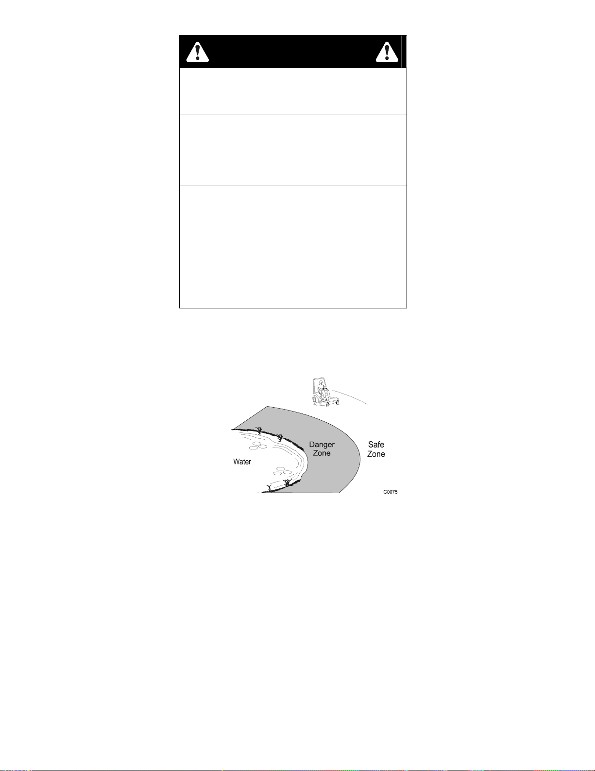
• See inside the back cover to determine the approximate slope angle of the
area to be mowed.
• Use a walk behind mower and/or a hand trimmer near drop- offs, ditches, steep
banks or water. This area can be dangerous, see Figure 1.
FIGURE 1
• Progressively greater care is needed as the slope increases.
• Always avoid sudden starting or stopping on a slope. If tires lose traction,
disengage the blades and proceed slowly off the slope.
• Avoid sudden starts when mowing uphill. Mower may tip backwards.
• Be aware that loss of traction may occur going downhill. Weight t r ansfer to
the front wheels may cause drive wheels to slip and cause loss of braking
and steering.
• Watch for ditches, holes, rocks, dips, and r ises t hat change the operating
angle, as rough terrain could overtur n the machine.
• Remove or mark obstacles such as rocks, t r ee lim bs, etc. from the mowing
area. Tall grass can hide obstacles.
• Use extreme care with grass catchers or attachments. These can change the
stability of the machine and cause loss of control.
• Follow the manufacturer’s recommendations for wheel weights or
counterweights to improve stability.
5
www.mymowerparts.com
Page 11

For Exmark Mower Parts Call 606-678-9623 or 606-561-4983
1.4.6 A Rollover Protection System (roll bar) is installed on t he unit .
WARNING
POTENTIAL HAZARD
♦ There is no rollover protection when the
roll bar is down.
WHAT CAN HAPPEN
♦ Wheels dropping over edges, ditches,
steep banks, or water can cause
rollovers, which may result in serious
injury, death or drowning.
HOW TO AVOID THE HAZARD
♦ Keep the roll bar in the raised and locked
position and use seat belt.
♦ Lower the roll bar only when absolutely
necessary.
♦ Do not wear seat belt when the roll bar is
down.
♦ Drive slowly and carefully.
♦ Raise the roll bar as soon as clearance
permits.
• Be certain that the seat belt can be released q u ickly if the machine is driven or
rolls into ponds of water.
• Check carefully for overhead clearances (i. e. branches, doorways, and
electrical wires) before driving under any objects and do not contact them.
1.4.7 Use EXTREME caution when backing up. LOOK BEHI ND YO U!
1.4.8 Stop the blades when crossing surfaces other than grass and when
transportingthe mower to and fr om the area to be mowed.
1.4.9 Never operate the mower with damaged g uards, shields, or covers. Always have
safety shields, guar ds, switches, and other devices in place and in proper working
condition.
1.4.10 DO NOT change the engine governor settings or overspeed the engine.
Operating an engine at excessive speed may increase the hazard of personal
injury.
1.4.11 Disengage PTO before starting engine.
1.4.12 Start
1.4.13 Keep hands, feet, and clothing away from rotat ing parts while the mower is being
1.4.14 Stop engine, wait for all moving parts to st op, remove key. Engage park ing brake:
Stop the engine and wait for all moving part s t o stop. Engage parking br ake:
the engine carefully with feet well away from the blades.
operated.
• Before checking, cleaning or work ing on the mower.
• After striking a foreign object (inspect the m ower for damage and make
repairs before restart ing and operating the mower).
• Before clearing blockages.
• Whenever you leave the mower.
• Before refueling.
• Before dumping the gr ass cat c her .
6
www.mymowerparts.com
Page 12

For Exmark Mower Parts Call 606-678-9623 or 606-561-4983
1.4.15 Before stopping the engine, place the t hrottle control midway between the “slow”
and “fast” positions. Allow the engine t o r un a m inim um of 15 seconds; then stop
the engine.
1.4.16 The fuel system is provided with a shut-off valve. Shut off the fuel:
• When the machine will not be used for a few days.
• During transport to and from t he job.
• When parked inside a building.
1.4.17 This mower was designed for one operator only. Keep all others away from
mower during operation.
1.4.18 DO NOT mow with the discharge deflector raised, removed or altered unless there
is a grass collection system or mulch kit in place and work ing properly.
1.4.19 Be aware of t he m ower discharge and direct discharge away from others.
1.4.20 DO NOT operate mower under the influence of alcohol or dr ugs.
1.4.21 Use extra care when approaching blind cor ners, shrubs, trees, or other obj ects
that may obscure vision.
1.4.22 If jump starting is required:
a) connect the positive (+) power cable from the positive post on the boost er
battery to the positive terminal post on the star ter solenoid switch (this post
has the positive battery cable attached to it).
b) connect the negative or ground cable (-) from the negative post on the
booster battery to the engine block as far away from the battery as possible.
c) disconnect battery cables in the reverse order after starting.
1.5 MAINTENANCE AND STORAGE
1.5.1 For engine maintenance, follow the engine m anufacturer’s recommendations
precisely as stated in the engine manual.
1.5.2 Disconnect the battery cable from t he negative battery post when the unit will be
allowed to sit for more than 30 days without use.
1.5.3 Allowing batteries to stand for an extended period of time without recharging them
will result in reduced performance and service life. To preserve optimum battery
performance and life, recharge batteries in storage when the open circuit voltage
drops to 12.4 volts.
Note: To prevent damage due to freezing, battery should be fully charged
before putting away for winter storag e.
1.5.4 Keep engine, engine area, and pump drive belt compar tment free fr om
accumulation of grass, leaves, excessive grease or oil, and ot her debris which
can accumulate in these areas. These materials can become com bustible and
may result in a fire.
1.5.5 Store fuel in a container specif ically desig ned for this purpose in a cool, dry
place.
1.5.6 Keep the mower and fuel container in locked storage to prevent children from
playing or tampering with them.
1.5.7 Diesel fuel powered equipment or fuel cont ainers should not be stored in a
basement or any enclosed area where open pilot lights or heat appliances are
present.
1.5.8 Maximum mowing results and safety can only be achieved if the mower is
properly maintained and operated correctly.
1.5.9 Check all bolts frequently to maintain proper tightness.
7
www.mymowerparts.com
Page 13
For Exmark Mower Parts Call 606-678-9623 or 606-561-4983
1.5.10 Keep all g uar ds, shields, and all safety devices in place and in safe working
condition.
1.5.11 Freq uently check for worn or deteriorating com ponents that could create a
hazard.
1.5.12 All replacem ent par ts must be the same as or equivalent to the par ts supplied as
original equipment.
WARNING
POTENTIAL HAZARD
♦ Hydraulic fluid escaping under pressure
can penetrate skin and cause injury.
WHAT CAN HAPPEN
♦ Fluid accidentally injected into the skin
must be surgically removed within a few
hours by a doctor familiar with this for m of
injury or gangrene may result.
HOW TO AVOID THE HAZARD
♦ Make sure all hydraulic fluid hoses and
lines are in good condition an all hydraulic
connections and fittings are tight before
applying pressure to hydraulic system.
♦ Keep body and hands away from pinhole
leaks or nozzles that eject high pressure
hydraulic fluid.
♦ Use cardboard or paper, not your hands,
to find hydraulic leaks.
♦ Safely relieve all pressure in the hydraulic
system by placing the motion control
levers in neutral and shutting off the
engine before perfor ming any work on the
hydraulic system.
WARNING
POTENTIAL HAZARD
♦ Fuel system components are under high
pressure.
WHAT CAN HAPPEN
♦ The use of improper components can
result in system failure, fuel leakage and
possible explosion.
HOW TO AVOID THE HAZARD
♦ Use only approved fuel lines and clamps
for high pressure systems.
8
www.mymowerparts.com
Page 14
For Exmark Mower Parts Call 606-678-9623 or 606-561-4983
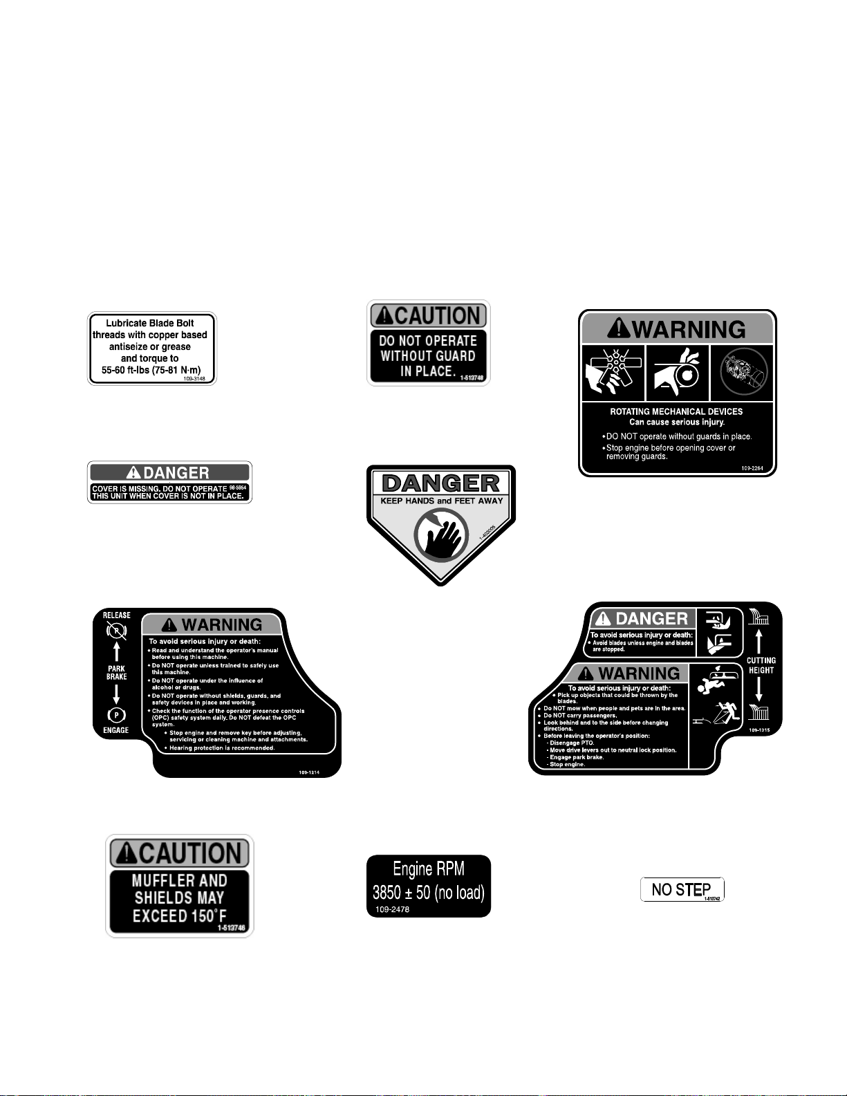
1.6 SAFETY SIGNS
1.6.1 Keep all safety signs legible. Remove all grease, dirt and debris from safety signs
and instructional labels.
1.6.2 Safety signs must be replaced if they are missing or illegible.
1.6.3 When new components are installed, be sur e that current safety signs are affixed
to the replaced components.
1.6.4 New safety signs may be obtained from your authorized Exmark equipment dealer
or distributor or from Exmar k Mfg. Co. Inc.
1.6.5 Safety signs may be affixed by peeling off the backing to expose the adhesive
surface. Apply only to a clean, dry surface. Smooth to remove any air bubbles.
1.6.6 Familiarize yourself with the following safety signs and inst r uct ion labels. They are
critical to the safe operation of your Exmark commercial mower.
PART NO. 109-3148
LOCATION: LH Side on Top Front
of Mower Deck
PART NO. 98-5954
LOCATION: Under Mower Deck
Belt Shield(s)-Top of
PART NO. 109-1214
LOCATION: LH Side of Console
PART NO. 1-513746
LOCATIONS: RH Air Cleaner
Mount Plate
PART NO. 1-513748
LOCATIONS: Bottom Side
of Floorpan
PART NO. 1-403005
LOCATION: Left and Right
Corners
Mower Deck
PART NO. 109-2478
LOCATION: Behind Deflector
Next to Buzzer
of
PART NO. 109-1215
LOCATION: RH Side of Console
PART NO. 109-2264
LOCATION: On Main Frame
Beneath Seat
PART NO. 1-513742
LOCATION: Top of Mower Deck
Belt Shields, Left
and Right
Sides
9
www.mymowerparts.com
Page 15
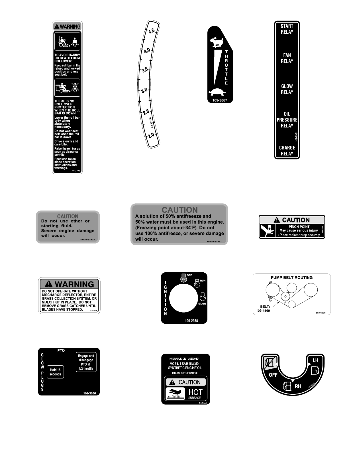
For Exmark Mower Parts Call 606-678-9623 or 606-561-4983
PART NO. 109-3067
LOCATION: Right of Throttle
Control on RH
Fuel Tank
PART NO. 107-2102
LOCATION: Inside Surface
of Upper Roll
PART NO. 1-633706
LOCATION: LH Side of Cutting
PART NO. 19426-87903
LOCATION: RH Air Cleaner
Bracket
PART NO. 1-303508
LOCATION: RH Side on Top Rear
of Mower Deck
PART NO. 109-3066
LOCATION: Top Front
RH Fuel Tank
Height Adjustment
Plate
PART NO. 19426-87881
LOCATION: Back of Radiator
Latch Plate
PART NO. 109-2358
LOCATION: Top Front
of RH Fuel Tank
PART NO. 1-523552
LOCATION: Top of Hydraulic
Reservoir,
PART NO.109-2951
LOCATION: Behind Air
Deflector,
Next to
Relays
PART NO. 109-2263
LOCATION: Rear of Unit,
Near Hood Prop
Rod
PART NO. 103-6936
LOCATION: Air Deflector
Behind Seat
PART NO. 103-0261
LOCATION: RH Front of
Console
10
www.mymowerparts.com
Page 16
For Exmark Mower Parts Call 606-678-9623 or 606-561-4983
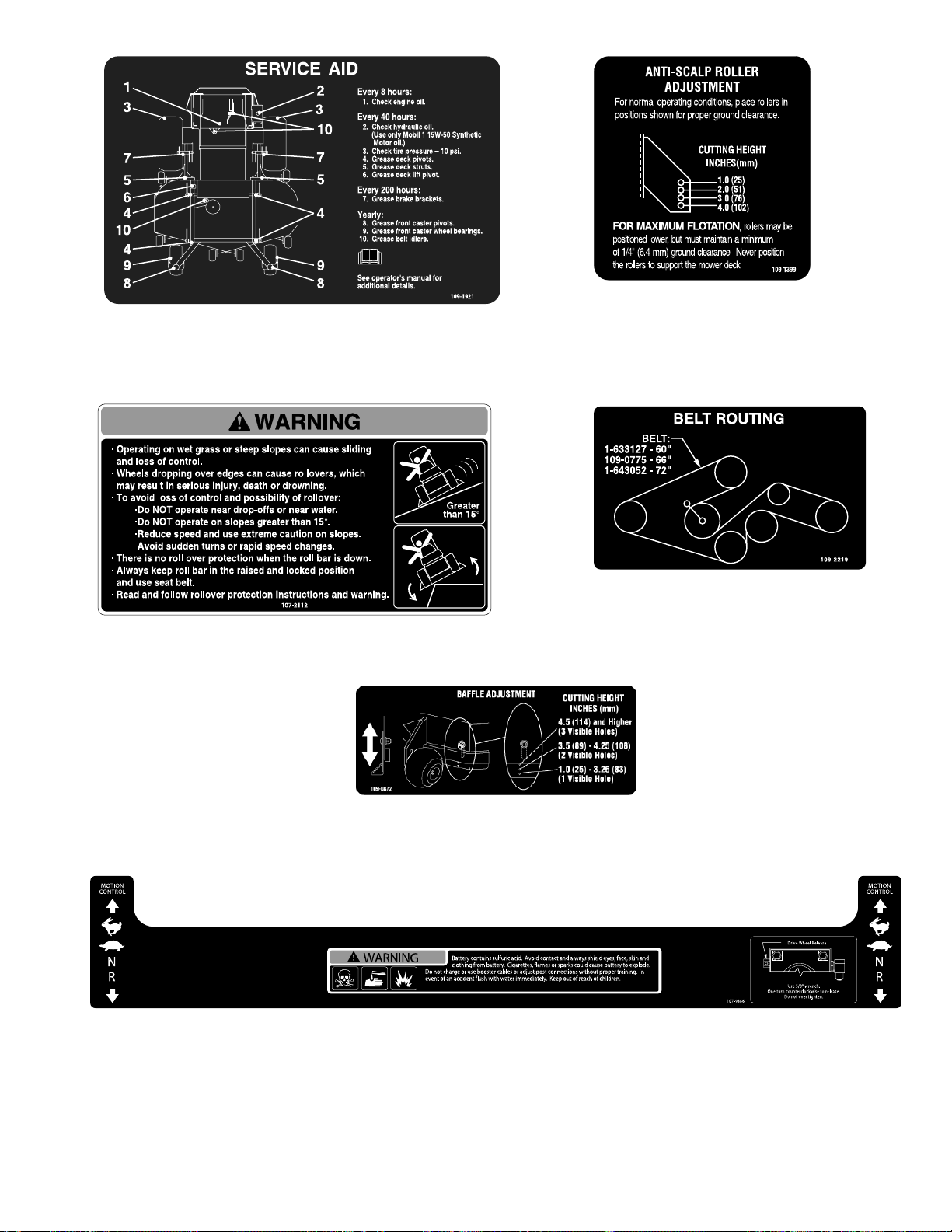
PART NO. 109-1921
LOCATION: Back of Seat
PART NO. 107-2112
LOCATION: Top Center of Floorpan
PART NO. 109-0872
LOCATION: Top of Mower Deck,
Front Left Edge near
Area shown on Decal
PART NO. 107-9866
LOCATION: Top of Console
PART NO. 109-1399
LOCATION: Front Center on Top
of Mower Deck
PART NO. 109-2219
LOCATION: Left of Center on Mower
Deck, Under Floor
Pan
11
www.mymowerparts.com
Page 17

For Exmark Mower Parts Call 606-678-9623 or 606-561-4983
2. SPECIFICATIONS
2.1 MODEL NUMBERS
Serial Nos. 670,000 and Higher: LXS25KD605; LXS25KD665; LXS25KD725
2.2 ENGINE
2.2.1 Engine Specifications: See your Engine Owner’s Manual
2.2.2 RPM: Full Speed: 3850 RPM ±50 (No Load) Idle: 1400 RPM
2.3 FUEL SYSTEM
2.3.1 Capacity: 15.5 gal. (58.6 L.)
2.3.2 Type of Fuel: Diesel fuel, 40 cetane or higher
2.3.3 Fuel Filter: In-line – 15 micron
Kubota P/N 12581-43012
2.3.4 Fuel Shut-Off Valve: 1/ 4 t ur n increments (“OFF”, right tank, left t ank)
2.3.5 Fuel gauge in left hand fuel tank.
2.4 ELECTRICAL SYSTEM
2.4.1 Charging System: External Alternator
2.4.2 Charging Capacity: 60 amps
2.4.3 Battery Type: BCI Group 26
2.4.4 Battery Voltage: 12 Volt
2.4.5 Polarity: Negative Ground
2.4.6 Fuses: (1) 20 amp blade type ; (1) 30 amp blade type
2.4.7 Safety Interlock System:
PTO must be disengaged, brake engaged, and motion control l evers out
(neutral lock) to start engi ne. (It is not necessary for the operator to be in the
seat to start the engine.)
O per at or m ust be in seat when PTO is engaged, brake is disengaged, or motion
control levers are moved in or engine will stop.
Engine will stop if either the left, the right, or both levers are moved from neut ral
lock position while brake is engaged.
2.5 COOLING SYSTEM
2.5.1 Fan: Electric with continuous operation with engine running.
2.5.2 Coolant Liquid: 50/50 mix of DexCool© extended life antifreeze and water.
2.5.3 Coolant Capacity: 4 quarts
2.6 OPERATOR CONTROLS
2.6.1 Steering and Motion Control:
Separate levers, on each side of the console, contr ol speed and dir ection of travel
of the respective drive wheels.
Steering is controlled by varying the position of the levers relative to each other.
Moving motion control levers outward
NOTE: Motion control levers are adjustable to two heights.
2.6.2 PTO Engagement Switch
mower blades.
2.6.3 Parking Brake Lever
2.6.4 Deck Height Adjustment Lever
2.6.5 Deck Lift Assist Lever:
: Engages parking brake.
www.mymowerparts.com
(in slots) locks the drive system in neutral.
: Engages electric clutch (t o dr ive belt) which engages
: Sets cutting height to desired position.
Foot pedal that assists in raising the deck .
12
Page 18

For Exmark Mower Parts Call 606-678-9623 or 606-561-4983
2.7 SEAT
2.7.1 Type: Deluxe suspension seat high back, low profile foam-in-place cushion (dampened,
adjustable spring suspension) and armrests, adjustable back angle.
2.7.2 Mounting: Hinged to tilt up for access to hydraulic pumps, battery and other
components. Held in tilted position with scissor-type links. Adjustable fore and aft seat
track.
2.7.3 Armrests: Molded adjustable flip-up
2.7.4 Seat Safety Switch: Incorporated into t he Safety Interlock System. T im e delay seat
switch eliminates rough ground cut-outs.
2.8 HYDROSTATIC GROUND DRIVE SYSTEM
2.8.1 Hydrostatic Pumps: Two Hydro Gear PW variable displacement piston pumps.
2.8.2 Wheel Motors: T wo Park er / Ross with 1 1/4” t aper ed shafts.
2.8.3 Hydraulic Oil Type: Use Mobil 1 15W-50 Synthet ic motor oil.
2.8.4 Hydraulic Oil Capacity: 5.5 qt. (5. 2 L.)
2.8.5 Hydraulic Filter: Replaceable cartridge type.
P/ N 103- 2146: 25 m icr ons, No bypass
2.8.6 Speeds: 0-12.0 mph (19.3 km/ hr ) forward
0-8.0 mph (12.9 km/hr ) r everse
2.8.7 Drive wheel release valves allow machine to be moved when engine is not running.
2.9 TIRES & WHEELS
Pneumatic (Air-Filled) Semi-Pneumatic
Quantity 2 2
Tread “Multi-Trac C/S” Smooth
Size 26 x 12.00-12 13 x 6.50-6
Ply Rating 4
Pressure 10 psi (69 kPa)
Drive Front Caster
armrests.
2.10 CUTTING DECK
2.10.1 Cut ting Width: 60 in. (152.4 cm)
66 in. (167.6 cm)
72 in. (182.9 cm)
2.10.2 Discharge: Side
2.10.3 Blade Size: (3 ea.) 60” Deck: 20.75 in. (52.7 cm)
66” Deck: 22.75 in. ( 57. 8 cm)
72” Deck: 24.75 in. ( 62.9 cm)
2.10.4 Blade Spindles: Solid steel spindles with 1.18” I . D. bearings.
2.10.5 Deck Drive: Electric clutch mounted on horizontal engine shaft . “B” Section belt
(with self-tensioning idler) from electric clutch to transfer shaft mounted on deck.
Blades are driven by one “B” Section belt (w/self-tensioning idler) f r om transfer
shaft on deck to blade spindles.
2.10.6 Deck: Full floating deck is attached to out-fr ont support frame. Six anti-scalp
rollers provide maximum turf protection. Deck design allows for bag ging, mulching
or side discharge.
Deck Depth
66” Deck: 6.0” (15.2 cm)
72” Deck: 6.0” (15.2 cm)
2.10.7 Cutting Height Adjustment: an extra-long cushioned lever is used to adjust the
cutting height from 1” (2.5 cm) to 5” ( 10. 2 cm.) in 1/4”(.64 cm) increment s. The
: 60” Deck: 6.0” (15.2 cm )
13
www.mymowerparts.com
Page 19

For Exmark Mower Parts Call 606-678-9623 or 606-561-4983
cutting height adjustm ent handle has a t ransport position and all adjustments
can be made while the operator remains seated. Units also have a foot
operated deck lift assist lever t o aid in r aising the deck.
2.10.8 Mulching Kit: Opt ional.
2.11 DIMENSIONS
2.11.1 Overall Width:
60” Deck
66” Deck
72” Deck
without deck deflector up deflector down
53.5 in. (135.9 cm) 61.4 in. (155.8 cm) 72.8 in. (184.9 cm)
57.3 in. (145.5 cm) 68.0 in. (172.7 cm) 79.4 in. (201.7 cm)
61.5 in. (156.2 cm) 74.3 in. (188.7 cm) 85.8 in. (217.9 cm)
2.11.2 Overall Length:
60” Deck 81.9 in. (208.0 cm) 92.5 in. (235.0 cm)
66” Deck 83.4 in (211.8 cm) 94.0 in (238.8 cm)
72” Deck 85.8 in. (217.9 cm) 96.4 in. (244.9 cm)
Roll Bar – Up Roll Bar - Down
2.11.3 Overall Height:
60”, 66” & 72” Decks 72.7 in. (184.7 cm) 53.6 in. (136.1 cm)
2.11.4 Tr ead Width: (center to center of tires, widthwise)
60” Deck 41.9 in. (106.4 cm) 37.3 in. (94.7 cm)
66” Deck 45.9 in. (116.6 cm) 42.3 in (107.4 cm)
72” Deck 45.9 in. (116.6 cm) 47.3 in. (120.1 cm)
Drive Wheels Casters
2.11.5 Wheel Base: (center of caster to center of drive tire)
Roll Bar - Up Roll Bar - Down
60” Deck 56.0 in. (142.2 cm)
66” Deck 57.6 in. (146.3 cm)
72” Deck 60.2 in. (152.9 cm)
2.11.6 Curb Weight:
60” Deck 1545 lbs. (701 kg)
66” Deck 1595 lbs. (723 kg)
72” Deck 1645 lbs. (746 kg)
2.12 TORQUE REQUIREMENTS
Bolt Location
Torque
Cutter Housing Spindle Nut .......................................160-185 ft-lbs. (217-251 N-m)
Blade Mounting Bolt...........................................................55-60 ft-lbs. (75-81 N-m)
Blade Drive Sheave Mounting Nut...............................90-110 ft-lbs. (122-149 N-m)
Engine Deck/Front Frame Mount Bolts..............................30-35 ft-lbs. (41-47 N-m)
Anti-Scalp Roller (See Figure 7)
Nyloc Nut..................................................................30-35 ft-lbs. (41-47 N-m)
Hex Capscrew...........................................................50-55 ft-lbs. (68-75 N-m)
Wheel Lug Nuts.............................................................90-95 ft-lbs. (122-129 N-m)
Wheel Motor Mounting Bolts ............................................72-77 ft -lbs. (98-104 N-m)
Wheel Hub Slotted Nut.............................................minimum 125 ft-lbs. (169 N-m)
Rollover Protection System (Roll Bar) Mounting Bolts .......30-35 ft-lbs. (41-47 N-m)
Deck Drive Jackshaft Nut ...............................................75-80 ft-lbs (102-108 N-m)
Clutch Retaining Bolt (secured with threadlocker)..............55-60 ft-lbs. (75-81 N-m)
14
www.mymowerparts.com
Page 20

For Exmark Mower Parts Call 606-678-9623 or 606-561-4983
3. OPERATION INSTRUCTIONS
3.1 CONTROLS
3.1.1 Familiarize yourself with all controls before operating the mower.
3.1.2 Motion Control Levers
controls the flow of hydraulic oil from the left hydrostatic pump to t he left drive
wheel motor. The right lever controls the flow of hydraulic oil from the r ight
hydrostatic pump to the right drive wheel motor.
IMPORTANT: To begin movement (forward or backward) the operator must
be in the seat, the brake lever must be disengaged (pushed down) before
the motion control levers can be moved in or the engine will shut off.
When levers are centered in the T-slot the drive system is in the neutral position.
With levers moved out in t he T-slot the drive system is in the neutral lock position
(See Figure 2).
: Located on each side of the console. The left lever
FIGURE 2
By moving both levers an equal amount forward or back from the neutral position
the machine can be caused to move forward or backward in a straight line.
Movement of the left lever forward will cause the left drive wheel to rotate in a
forward direction. Movement of the right lever f orw ard will cause the right
drive wheel to rotate in a forward direction. To stop forward travel, pull the
levers back to the neutral position.
To turn left while moving forward, move the left lever back toward neutral to
slow the left drive wheel.
To turn right while moving forward, move the right lever back toward neutral t o
slow the right drive wheel.
To make a zero turn to the left, pull the left lever back beyond neutral while
holding the right lever slight ly ahead of neutral.
To make a zero turn to the right, pull the right lever back beyond neutr al while
holding the left lever slight ly ahead of neutral.
Pulling the levers back from t he neutral position will cause the respective drive
wheels to rotate in a reverse direction (spring tension can be felt when moving
into reverse from neutr al) .
To turn to the left while backing, move the left lever forward toward neutral. To
turn to the right while backing , m ove the right lever forward toward neutral.
15
www.mymowerparts.com
Page 21

For Exmark Mower Parts Call 606-678-9623 or 606-561-4983
CAUTION
POTENTIAL HAZARD
Machine can spin very rapidly by
♦
positioning one lever too much ahead of
the other.
WHAT CAN HAPPEN
Operator may lose control of the
♦
machine, which may cause damage to
the machine or injury.
HOW TO AVOID THE HAZARD
♦ Use caution when making turns.
♦ Slow the machine down before making
sharp turns.
3.1.3 Tracking Adjustment Knob: Located under the seat on the LH pum p cont rol
link. Rotating this k nob allows f ine t uning adjustments so that the machine
tracks straight with the dr ive levers in the full forward position.
Stop machine and wait for all moving parts t o stop. Engage park brake. Unhook
seat latch and tilt seat forward to gain access to the tracking k nob. Rotate the knob
clockwise (as viewed from the rear of the machine) to cause the machine to track
more to the right and counterclockwise to cause the machine to track more to t he
left. Adjust in quar ter-turn increments until the m achine tracks straight. Check that
the machine does not creep when in neutral with the park brakes disengaged.
IMPORTANT: Do not rotate the knob too far, as this may cause the machine
to creep in neutral. Refer to section 4.2. 11 f or cont rol l inkage adjustment.
3.1.4 Brake Lever
: Located on left side of unit , just to the front of the console. The
brake lever engages a parking brake on the drive wheels.
Pull the lever up and rearward to engage the brake.
Push the lever forward and down to disengage the brake.
The unit must be tied down and brake engaged when transpor ting.
3.1.5 Fuel Shut- Off Valve
: Located directly below right side of console, next to cubby.
The fuel shut-off valve is used to shut off the fuel when the machine will not be
used for a few days, during transport to and from the job site, and when park ed
inside a building. The valve has three positions, each position made in 1/ 4 t urn
increments.
FUEL FLOW VALVE HANDLE POSITION
“OFF” RIGHT
RIGHT TANK DOWN
LEFT TANK LEFT
3.1.6 Fuel Gauge: Located on the left fuel tank.
The fuel gauge monit ors the amount of fuel in the left tank only. Use the fuel
from the right fuel tank first . When the rig ht fuel tank is empty, switch to the left
fuel tank. Fuel gauge will monitor the remaining fuel.
3.1.7 Coolant Temperat ur e Gauge:
Located at the front of the left fuel tank. The
coolant temperature gaug e m onit ors the temperature of t he engine coolant. An
engine overheating condition is indicated by the red area on the g auge and an
alarm will sound (See Section 3.1.16).
16
www.mymowerparts.com
Page 22

For Exmark Mower Parts Call 606-678-9623 or 606-561-4983
3.1.8 Voltmeter:
left fuel tank . The voltmeter measures the voltage out put of the alternator. Both
high and low voltages will potentially damage the battery.
3.1.9 Ignition Switch
The ignition switch is used to start and stop the engine. The switch has three
positions “OFF”, “ON” and “START”. Insert k ey into switch and rot ate clockwise
to the “ON” position. Rotat e clockwise to the next position to engage the star t er
(key must be held against spring pr essur e in t his position).
Brake must be engaged, motion control levers out (neutr al l ock position)
and PTO switch “OFF” to start engine. (It is not necessary for the operator to
be in the seat to start the engine. )
3.1.10 PTO Engagement Switch
Switch must be pulled out to the “ROTATE” position to engage the blades.
Switch is pushed in to the “STOP” position to stop the blades.
3.1.11 Glow Plug Light:
when the glow plug switch is depressed. The glow plug light indicates the g low
plugs are preheating the combustion cham ber .
3.1.12 Low Oil Pressure Light:
engine oil pressure is low or lost.
3.1.13 Glow Plug Switch:
heat glow plugs as required by chart below prior to start ing engine.
NOTE: The glow plug light, locat ed near the glow plug switch, will illuminate
when the switch is depressed. The glow plug light indicates the glow plugs are
preheating the combustion chamber.
3.1.14 Throttle Control
Throttle is used to control engine speed. Moving throttle lever forward will increase
engine speed and moving throttle lever to the rear will decrease engine speed.
3.1.15 Hour Meter
pressure switch installed in the engine block and it record s t he num ber of hours
that the engine has run. If the ignition switch is left on without engine r unning,
hour meter will not run.
NOTE: This switch is not a low oil sensor and will not alert the operator if the
engine oil is low.
3.1.16 Warning Buzzer
electrical panel. The buzzer is a warning signal for t he following circumstances:
a) When the eng ine is r unning and the buzzer emits a continuous beep, the
Located next to the Coolant Temperature Gauge at the front of the
: Located on right fuel tank.
Located on the right fuel tank. The glow plug light comes on
Located to the right f uel t ank. Light will come on when
Located on the right fuel tank. Depress and hold switch to
Ambient Temperature Hold Glow Plugs On
Above 50°F (10°C) NO NEED
50°F (10°C) to 23°F (-5°C) Approx. 5 seconds
Below 23°F (-5°C) Approx. 10 seconds
Limit of continuous use 20 seconds
: Located on right fuel tank.
: Located on the right fuel t ank. The hour meter is connected t o a
: Located behind the seat under the air def lect or on the
buzzer is warning the user that the engine is overheating. Perform the
following steps.
1. Disengage the mower blades, and idle down the engine.
2. Look at the temper ature gauge to determine if temperature continues to
increase. If it does, tur n the unit off and allow the engine and engine
components to cool.
: Located on right fuel tank.
GLOW PLUG CHART
17
www.mymowerparts.com
Page 23

For Exmark Mower Parts Call 606-678-9623 or 606-561-4983
3. Check the coolant level. If necessary fill with coolant as described in
Section 4.1.5.
4. Remove any debris on or around the radiator that may restrict airflow.
5. Check to see if the water pump/alternator belt is intact . If belt is
missing, do not run unit, as unit can overheat and dam age the engine.
See Engine Service Dealer.
b) When the eng ine is r unning and the buzzer emits intermittent beeps, t he
buzzer is warning the user that the engine oil pressure is low. Perform the
following steps.
1. Turn the unit off, allow the engine and engine components t o cool.
2. Check the oil level and fill, if necessary, as described in Section 4.1.4.
3. Check for oil leaking from eng ine. If the engine is leaking , see Engine
Service Dealer.
3.1.17 Drive Wheel Release Valves
pumps. Drive wheel release valves are used to release the hydrostatic drive
system to allow the machine to be pushed without the engine running. Unhook
seat latch and tilt seat up to gain access to pum ps.
With a 5/8 wrench, t ur n both valves one turn counter-clockwise to release drive
system. Turn clockwise to reset system. DO NOT overtighten. DO NOT tow
machine.
: Located on the top right f r ont cor ner of hydrostatic
3.2 PRE-START
3.2.1 Fill fuel tanks. For best r esults use only clean, fresh diesel fuel with a cetane
rating of 40 or higher .
NOTE: do not use kerosene or gasoline instead of diesel fuel. Failure t o observe
this will damage the engine.
DO NOT add oil to fuel.
DO NOT overfill fuel t ank. Never fill the fuel t ank so that the fuel level rises above
a level that is 1/2” below the bottom of t he filler neck to allow for fuel expansion
and prevent fuel spillage.
3.2.2 Make sure you understand the controls, their locations, their functions, and their
safety requirements.
3.2.3 Refer to Maintenance, Section 4, and perf orm all the necessary inspection and
maintenance steps.
3.3 OPERATING INSTRUCTIONS
3.3.1 Raise the Roll Bar: Operate units with the roll bar in t he raised and locked position
and use seat belt. There is no rollover protect ion when the roll bar is down. If it is
necessary to lower roll bar do not wear the seat belt. Raise the roll bar as soon as
clearance permits.
3.3.2 Open fuel shut-off valve
3.3.3 Starting Engine
a) Brake must be engaged, motion control levers out (neutral lock
position) and PTO switch “OFF” to start engine. (It is not necessary for
the operator to be in the seat to star t the engine.)
b) On a warm engine, place the throttle in the “SLOW” posit ion.
:
(left or right tank).
On a cold engine (below 14° F (-10° C)), place the throttle in the “MIDWAY”
position.
Note: Do not use fuel left over from summer.
18
www.mymowerparts.com
Page 24

For Exmark Mower Parts Call 606-678-9623 or 606-561-4983
c) Turn the ignit ion switch to t he “ ON” position. Depress the glow plug switch
and the glow plug light will turn on. Hold switch according to chart in section
3.1.13. Turn the ignition switch to the “START” position. Release t he ignition
switch as soon as the engine starts.
IMPORTANT:
(10) seconds at a time. If the engine does not start, allow a 30 second
cool-down period between starting attempts. Failure to follow these
guidelines can burn out the starter motor and/or fuel sol enoi d.
d) Move the throttle to the “SLOW” (if in “MIDWAY”) and let the engine warm up
a few minutes before moving the thr ottle to the “FAST” position.
3.3.4 Engaging PTO
POTENTIAL HAZARD
♦ The rotating blades under the mower
WHAT CAN HAPPEN
♦ Blade contact can cause serious injury or
HOW TO AVOID THE HAZARD
♦ DO NOT put hands or feet under t he
DO NOT crank the engine continuously for more then ten
:
DANGER
deck are dangerous.
kill you.
mower or mower deck when the blades
are engaged.
DANGER
POTENTIAL HAZARD
♦ An uncovered discharge opening will
allow objects to be thrown in an
operator’s or bystander’s direction. Also,
contact with the blade could occur.
WHAT CAN HAPPEN
♦ Thrown objects or blade contact can
cause serious injury or death.
HOW TO AVOID THE HAZARD
♦ Never operate the mower with the
discharge deflector raised, r emoved, or
altered unless there is a grass collection
system or mulch kit in place and working
properly.
The PTO push-pull switch engages the cut t ing blades. Be sure that all persons
are clear of the mower deck and dischar ge area before engaging PTO.
IMPORTANT
Set throttle to "midway" position. Pull outward on the switch to the “ROTATE”
position. Accelerate to full throttle to begin mowing.
: Operator must be in seat before the PTO can be engaged.
19
www.mymowerparts.com
Page 25

For Exmark Mower Parts Call 606-678-9623 or 606-561-4983
3.3.5 Stopping PTO
“STOP” position stopping t he PTO.
3.3.6 Stopping Engine
control levers out to the neutral lock position and set parking brake.
Before stopping the eng ine, place t he throttle control midway between the “slow”
and “fast” positions. Allow the engine t o r un a m inim um of 15 seconds; then stop
the engine.
Rotate ignition switch to “OFF” posit ion. Rem o ve the key to prevent children or
other unauthorized persons from star t ing engine.
Close fuel shut-off valve when machine will not be used for a few days, when
transporting, and when the unit is park ed inside a building.
3.4 TRANSPORTING
3.4.1 Transporting a Unit: Use a heavy-duty trailer or truck to transport the m achine. Lock
brake and block wheels. Securely fasten the machine to the trailer or truck with
straps, chains, cable, or ropes. Be sure t hat the trailer or truck has all necessary
lighting and marking as required by law. Secure a trailer with a safety chain.
: Set throttle to the “m idway” position. Push in on t he switch to t he
: Bring unit to a full stop. Disengage the PTO, move motion
CAUTION
POTENTIAL HAZARD
♦ This unit does not have proper turn
signals, lights, reflective markings, or a
slow moving vehicle emblem. These
items are required to drive on a public
street or roadway.
WHAT CAN HAPPEN
♦ Driving on a street or roadway without
such equipment is dangerous and can
lead to accidents causing personal injury.
♦ Driving on a street or roadway without
such equipment may also be a violation of
State laws and the operator may be
subject to traff ic tickets and/or fines.
HOW TO AVOID THE HAZARD
♦ Do not drive a unit on a public street or
roadway.
20
www.mymowerparts.com
Page 26

For Exmark Mower Parts Call 606-678-9623 or 606-561-4983
CAUTION
POTENTIAL HAZARD
♦ Loading a unit on a trailer or truck
increases the possibility of backward tip-
over.
WHAT CAN HAPPEN
♦ Backward tip-over of the unit could cause
serious injury or death.
HOW TO AVOID THE HAZARD
♦ Use extreme caution when operating a
unit on a ramp.
♦ Use only a single, full width ramp; DO
NOT use individual ramps for each side of
the unit.
♦ If individual ramps must be used, use
enough ramps to create an unbroken
ramp surface wider than the unit.
♦ DO NOT exceed a 15° angle between
ramp and ground or between ramp and
trailer or truck.
♦ Avoid sudden acceleration while driving
unit up a ramp to avoid tipping backward.
♦ Avoid sudden deceleration while backing
unit down a ramp to avoid tipping
backward.
3.4.2 Loading a Unit: Use extreme caution when loading units on tr ailer s or t rucks. One
full width ramp that is wide enough to extend beyond the rear tires is
recommended instead of individual ramps f or each side of the unit. The lower rear
section of the tractor frame extends back between the rear wheels and serves as a
stop for tipping backward. Having a full width ramp provides a surface for t he
frame members to contact if the unit starts to tip backward.
If it is not possible to use one f ull width ram p, use enough individual ramps to
simulate a full width continuous ramp.
Ramp should be long enough so that the angles between the ramp and the ground
and the ramp and the trailer or tr uck do not exceed 15°. A steeper angle may
cause mower deck components to get caught as t he unit moves from ramp to
trailer or truck. St eeper angles may also cause the unit to tip backward. If loading
on or near a slope, position the trailer or t ruck so it is on the down side of the slope
and the ramp extends up the slope. This will minimize the ramp ang le. The trailer
or truck should be as level as possible.
DO NOT attempt to tur n t he unit while on the ramp, you may lose control and drive
off the side.
Avoid sudden acceleration when driving up a ramp and sudden deceleration when
backing down a ramp. Both maneuvers can cause the unit to tip backward.
21
www.mymowerparts.com
Page 27

For Exmark Mower Parts Call 606-678-9623 or 606-561-4983
4. MAINTENANCE & ADJUSTMENTS
WARNING
POTENTIAL HAZARD
♦ While maintenance or adjustments are
being made, someone could start the
engine.
WHAT CAN HAPPEN
♦ Accidental starting of the engine could
seriously injure you or other bystanders.
HOW TO AVOID THE HAZARD
♦ Remove the key from the ignition switch
and engage parking brake before you do
any maintenance.
WARNING
POTENTIAL HAZARD
♦ The engine can become very hot.
WHAT CAN HAPPEN
♦ Touching a hot engine can cause severe
burns.
HOW TO AVOID THE HAZARD
♦ Allow the engine to cool completely before
service or making repairs around the
engine area.
4.1 PERIODIC MAINTENANCE
4.1.1 Check rollover protection system (roll bar) pins
Service Interval: Daily
a) Make sure latch pin and hair pin are fully installed and lanyard is in good
condition.
b) Check seat belt for cuts or wear. Replace if necessary
4.1.2 Check for loose hardware
Service Interval: Daily
a) Stop engine, wait for all moving parts to stop, and remove ke y. Engage
parking brake.
b) Visually inspect machine for any loose hardware or any other possible
problem. Tighten hardware or correct the problem before operating.
4.1.3 Check mower blades
Service Interval: Daily
a) Stop engine, wait for all moving parts to stop, and remove ke y. Engage
parking brake.
b) Lift deck and secure in raised position as stated in Section 4.1.8.
c) Inspect blades and sharpen or replace as required.
.
.
22
www.mymowerparts.com
Page 28

For Exmark Mower Parts Call 606-678-9623 or 606-561-4983
d) Re-install the blades (if they were removed) in the following order (See
Figure 3):
1) Install bushing through blade with bushing f lange on bottom (grass)
side of blade.
2) Install bushing/blade assembly into spindle.
3) Install blade bolt and spring disc washer. Be sure the spring disc
washer cone is installed towards the bolt head. Place wrench on the top
spindle nut then torque the blade bolts t o 55- 60 ft-lbs. (75-81 N-m).
FIGURE 3
WARNING
POTENTIAL HAZARD
♦ Incorrect installation of the blade or
components used to retain the blade can be
dangerous.
WHAT CAN HAPPEN
♦ Failure to use all original components and
assembled as shown could allow a blade or
blade component to be thrown out from
under the deck resulting in serious personal
injury or death.
HOW TO AVOID THE HAZARD
Always install the original Exmark blades,
♦
blade bushings, spring disc washers, and
blade bolts as shown.
4.1.4 Check engine oil level:
Service Interval: Daily
a) Stop engine and wait for all moving parts to stop. Make sure unit is on a
level surface.
b) Check with engine cold.
c) Clean area around dipstick. Remove dipstick and wipe oil off. Reinsert the
dipstick and push it all the way down into the tube. Remove the dipstick
and read the oil level.
23
www.mymowerparts.com
Page 29

For Exmark Mower Parts Call 606-678-9623 or 606-561-4983
d) If the oil level is low, raise radiator to gain access to oil fill, wipe off the area
around the oil fill cap, remove cap and f ill to the “FULL” mark on the
dipstick. Use oil as specified in Engine Owner’s Manual. DO NOT overfill.
IMPORTANT: DO NOT operate the engine with the oil level below the
“LOW” (or “ADD”) mark on the dipstick, or over the “FULL” mark.
WARNING
POTENTIAL HAZARD
♦ If the radiator prop r od is not secur ely
position in the notch the radiator may f a ll.
WHAT CAN HAPPEN
♦ Falling radiator could cause serious
injury.
HOW TO AVOID THE HAZARD
♦ Be sure the prop rod is engaged securely
4.1.5 Check engine coolant level
Service Interval: Daily
a) Stop engine and wait for all moving parts to stop. Make sure unit is on a
level surface.
b) Check with engine cold.
c) View coolant level in overflow bottle on the left side of the engine
compartment. Coolant level should be at the indicator line on the overflow
bottle.
d) If the coolant level is low, open hood or raise radiator, remove the cap to
the overflow bottle and fill to the indicat or line. Units should only be filled
with a 50/50 mix of Dex-Cool© extended life coolant and water. Dex-Cool©
can be identified by its orange color.
in the notch at the far rig ht side of the slot.
WARNING
POTENTIAL HAZARD
♦ Engine coolant is hot and pressurized.
♦ Radiator and surrounding parts are hot .
WHAT CAN HAPPEN
♦ Spray or steam from hot, pressurized
liquid in the engine cooling system and
touching a hot radiator may cause severe
burns.
HOW TO AVOID THE HAZARD
♦ Allow the engine to cool completely before
removing the radiator cap or servicing any
component of the cooling system.
24
www.mymowerparts.com
Page 30

For Exmark Mower Parts Call 606-678-9623 or 606-561-4983
CAUTION
POTENTIAL HAZARD
♦ Engine coolant is toxic.
WHAT CAN HAPPEN
♦ Swallowing coolant can cause poisoning.
HOW TO AVOID THE HAZARD
♦ Do not swallow
♦ Keep out of reach of children and pets.
4.1.6 Check safety interlock system.
Service Interval: Daily
a) Check starting circuit. Starter should crank with, parking brake engaged,
PTO disengaged and motion contro l levers m oved out in t he neutral lock
position. The operator does not need to be in t he seat to start the engine.
Try to start with operator in seat, parking brak e di sengaged, PTO
disengaged and motion control levers in the neutral lock posit ion - starter
must not crank.
Try to start with operator in seat, parking brak e engaged, PTO engaged and
motion control levers in the neutral lock position - starter must not crank.
Try to start with operator in seat, parking brak e engaged, PTO
disengaged, and the left motion control lever in, starter must not
crank, repeat again with the right lever in, then with both l evers i n -
starter must not crank.
b) Check the kill circuits. Run engine at one-third thr ottle, disengage parking
brake and raise off of seat ( but do not get off of machine) engine must
stop after approx. 1/2 second has elapsed (seat switch circuit has a time
delay switch to prevent cut-outs on rough terrain).
Run engine at one-third throttle, engage PTO and raise off of seat (but do
not get off of machine) engine must stop af t er 1/2 second has elapsed.
Run engine at one-third throttle, with brake disengaged, move levers in and
raise off seat (but do not get off of machine) engine must stop aft er 1/2
second has elapsed.
Again, run engine at one-thir d throttle, brake engaged, and move left
motion control lever in - engine must st op.
Repeat again moving the right lever in, t hen m oving bot h l evers in engine must stop whether operator is on seat or not.
NOTE: If machine does not pass any of these tests, do not operate.
Contact your authorized EXMARK SERVICE DEALER.
IMPORTANT: It is essential that operator safety mechanisms be
connected and in proper operating condition prior to use for mowing.
25
www.mymowerparts.com
Page 31

For Exmark Mower Parts Call 606-678-9623 or 606-561-4983
4.1.7 Clean engine cooling system
Servi ce I nt erval: Daily or more often in dry conditions
:
CAUTION
POTENTIAL HAZARD
♦ Excessive debris and damaged or
missing rubber seals can cause the
engine to overheat.
WHAT CAN HAPPEN
♦ Overheating the engine may cause
severe damage.
HOW TO AVOID THE HAZARD
♦ Clean debris from radiator screen and
core daily.
a) Stop engine, wait for all moving parts to stop, and r emove key. Engage
parking brake.
b) Wipe debris from screen in eng ine cover. Rotate engine cover forward and
wipe debris from radiator core as required. Inspect seals in engine cover
and replace as necessary.
4.1.8 Clean grass build-up under deck
Service Interval: Daily
a) Stop engine, wait for all moving parts to stop, and remove key. Engage
parking brake.
b) Raise deck to the transport (5” (12.7 cm) cut t ing height) position. Lift t he
front of unit and support unit using jack stands or eq uivalent suppor t .
.
CAUTION
POTENTIAL HAZARD
♦ Raising the mower deck for service or
maintenance relying solely on mechanical
or hydraulic jacks could be dangerous.
WHAT CAN HAPPEN
♦ The mechanical or hydraulic jacks may
not be enough support or may
malfunction allowing the unit to fall, which
could cause injury.
HOW TO AVOID THE HAZARD
♦ DO NOT rely solely on mechanical or
hydraulic jacks for support. Use adequate
jack stands or equivalent support.
c) Clean out any grass build-up fr om under side of deck and in discharge chute.
26
www.mymowerparts.com
Page 32

For Exmark Mower Parts Call 606-678-9623 or 606-561-4983
4.1.9 Check tire pressures
Service I nt erval: 40 hrs.
a) Stop engine, wait for all moving parts to stop, and remove key. Engage
parking brake.
b) Check tire pressure in drive tires.
c) Inflate dr ive tires to 10 psi (69 kPa).
d) Semi-pneumatic caster tires do not need to be inflated.
NOTE: Do not add any type of tire liner or foam fill material to the tires.
Excessive loads created by foam filled tires may cause failures t o the hydro
drive system, frame, and other com ponents. Foam filling tires will void the
warranty.
4.1.10 Check condition of belts
Service I nt erval: 40 hrs.
a) Stop engine, wait for all moving parts to stop, and remove key. Engage
parking brake.
b) Unhook seat latch and tilt seat up. Remove the air detector panel on front
side of the engine compartment to check pump drive belt and alternator
belt.
c) Remove left and right belt shields on deck and lift up floor pan to inspect
deck drive belt.
d) Check under machine to inspect the mule drive belt.
e) See Sections 4.2.3, through 4.2.5 for belt adjustment.
4.1.11 Check hydraulic oil level
Service Interval: 40 hrs.
a) Stop engine and wait for all moving parts to stop.
b) Clean area around hydraulic reservoir cap and remove cap. Oil level
should be to the top of the baf fle inside the tank. If not, add oil. Use only
Mobil 1 15W-50 synthetic motor oil. Replace hydraulic reservoir cap and
tighten until snug. Do not over t i ghten.
NOTE: The baffle is labeled “HOT” and “COLD”. The oil level varies with
the temperature of the oil. The “HOT” level shows the level of oil when it is
at 225°F (107°C). The “COLD” level shows the level of the oil when it is at
75°F (24°C). Fill to the appropriat e level depending upon the temperature
of the oil. For example: If the oil is about 150°F (65°C), fill to halfway
between the “HOT” and “COLD” levels. If the oil is at room temperature
(about 75°F (24°C)), fill only to the “COLD” level.
:
:
:
4.1.12 Lubricate gr ease fittings
Service Interval: Refer to chart.
a) Stop engine, wait for all moving parts to stop, and remove key. Engage
parking brake.
b) Lubricate fittings with one to two pumps of NGLI g rade #2 multi-purpose
gun grease.
:
27
www.mymowerparts.com
Page 33

For Exmark Mower Parts Call 606-678-9623 or 606-561-4983
Refer to the following chart for fitting locat ions and lubr icat ion schedule.
LUBRICATION CHART
FITTING
LOCATIONS
1. Front Caster wheel hubs
2. Front Caster Pivots
3. Height Adj. Shaft Bearings 1 5 40 hours
4. Deck Drive Belt Idler Arm
5. Brake Brackets 1 2 200 hours
6. Mule Drive Belt Idler Arm
7. Pump Drive Belt Idler Arm
8. Deck Rear Struts 1 2 40 hours
∗ See Section 4.1.12 c) f or special lubr ication instructions on the front cast er pivots and
Section 4.1.23 for special lubrication inst r uct ions on the front casters wheel hubs.
No. 6 (Mule Drive Belt Idl er Arm)
Located Under Engine Frame
No. 7 (Pump Dri ve Bel t Idler Arm)
Located Under Engine Frame
INITIAL
PUMPS
∗0
∗0
1 1 Yearly
1 1 Yearly
1 1 Yearly
NO. of
PLACES
2
2
SERVICE
INTERVAL
∗yearly
∗yearly
c) Lubr icate front caster pivots once a year. Remove hex plug and cap. T hr ead
grease zerk in hole and pump with grease until it oozes out around top bearing.
Remove grease zerk and thread plug back in. Place cap back on.
4.1.13 Service air cleaner
.
First Service Interval: 50 hrs.
Normal Service Interval: 100 hrs.
Replacement Interval: 600 hrs.
(More often under severe conditions.)
See Engine manual for additional informati on.
a) Stop engine, wait for all moving parts to stop, and remove ke y. Engage
parking brake.
b) Unhook (2) air filter canister latches to gain access to t he air cleaner
element.
c) Remove air cleaner canister cover and remove outer element.
d) Check the condition of the paper element. Replace if dirty, bent or
damaged.
e) Check the condition of the inner element. Replace whenever it appears
dirty, typically every other time the paper element is replaced. Clean t he
base around the inner element before removing, so dirt does not get into
the engine.
f) DO NOT wash or use pressurized air to clean paper element or inner element.
g) Reinstall elements. Position the cover so that the rubber dust ejector is
pointing downward and secure with retaining clips.
28
www.mymowerparts.com
Page 34

For Exmark Mower Parts Call 606-678-9623 or 606-561-4983
4.1.14 Chang e engine oil
Service Intervals:
First servi ce interval – 50 hrs.
Normal service interval – 100 hrs.
(yearl y if operated less than 100 hrs.)
(m ore of t en under heavy l oad or hi gh t emperat ures).
a) Stop engine, wait for all moving parts to stop, and r em o ve k ey. Engage
parking brake.
b) Drain oil while engine is warm from operation.
c) Fasten deck belt spans together with mechanics wire or tie wrap to prevent
oil from draining onto belt .
d) Remove the oil drain plug. Allow oil to drain then replace the drain plug.
e) Replace the oil filter every other oil change.
f) Clean around oil filter and unscrew filter to rem ove.
g) Before reinstalling a new filter, apply a thin coating of fresh clean oil on the
surface of the gasket.
h) Turn filter clockwise until rubber seal contacts the filter adapter, then tig h t en
filter an additional 1 full turn.
i) Unlatch radiat or and lift it up to access oil fill. Clean around oil fill cap and
remove cap. Fill to specified capacity and replace cap. Use oil
recommended in engine owner’s manual. DO NOT overfill.
j) Remove wire or tie wrap from belt spans.
k) Start the engine at idle for 5 minutes. Stop eng ine and wait thr ee minutes,
then check the oil level. If r equired, add oil to bring level to the “ FULL” mark
on the dipstick. DO NOT overfill.
l) Check for leaks, including around the oil filter.
4.1.15 Drain fuel filter
Service Interval: 100 hrs.
a) Stop engine, wait for all moving parts t o stop, and remove key. Engage
parking brake.
b) Place a drain pan under the fuel filter and loosen t he dr ain plug
approximately 1 turn.
c) Water should drain.
d) When fuel beg ins to flow from the filt er, tighten the drain plug.
IMPORTANT: Water or other contaminant s in fuel can severely damage fuel
pump and/or the other engine components.
4.1.16 Lubricate brake handle pivot
Service Interval: 160 hrs.
a) Stop engine, wait for all moving parts t o stop, and remove key. Engage
parking brake.
b) Lubricate bronze bushings on brake handle pivot with a spray type lubricant
or light oil.
4.1.17 Lubricat e br ake rod bushings
Service Interval: 160 hrs.
a) Stop engine, wait for all moving parts t o stop, and remove key. Engage
parking brake.
b) Unhook seat latch and tilt seat up.
:
:
:
:
29
www.mymowerparts.com
Page 35

For Exmark Mower Parts Call 606-678-9623 or 606-561-4983
c) Lubricate bronze bushings on each end of brake rod shaft with a spray type
lubricant or a light oil (bushings ar e locat ed to the inside of the flange bearings).
4.1.18 Lubricate mot ion control bronze bushings
Service Interval: 160 hrs.
a) Stop engine, wait for all moving part s t o st op, and remove key. Engage
parking brake.
b) Unhook seat latch and tilt seat up.
c) Lubricat e br onze bushing s on flange bearings securing the m ot ion cont r ol
arm shafts with a light oil or a spr ay type lubricant .
4.1.19 Change hydraulic system filter
Service I nt erval: After First 250 hrs.
Then yearl y t hereaf t er
NOTE: Use only Exmark Part No. 103- 2146.
a) Stop engine, wait for all moving parts to stop, and remove ke y. Engage
parking brake.
b) Raise seat.
c) Carefully clean area around filter. It is important that no dirt or
contamination enter hydraulic system.
d) Unscrew filter to remove and allow oil to drain from reservoir.
IMPORTANT: Before reinstalling new filter, fill it with Mobil 1 15W-50 and
apply a thin coat of oil on the surface of the rubber seal.
Turn filter clock wise until rubber seal contacts the filter adapter , then
tighten the filter an addit ional 2/ 3 to 3/4 turn.
e) Fill reservoir as stated in Section 4.1.11
f) Raise the rear of machine up and support with jack stands (or equivalent
support) just high enough t o allow drive wheels to turn freely.
g) Start engine and move throttle control to full throttle position. Move the
speed control levers to the full forward position and run for several minutes.
Shut down machine and recheck oil level.
Do not change hydraulic system oil more frequently than recommended
(except for what can be drained when changing f ilt er ), unless it is felt the oil
has been contaminated or been extremely hot.
Changing oil unnecessarily could damage hydraulic system by
introducing contaminates into the system.
4.1.20 Check bat t ery charge
Service Interval: Monthly
Allowing batteries to stand for an extended period of time without recharging
them will result in reduced performance and ser vice life. To preserve optimum
battery performance and lif e, recharge batteries in storage when the open
circuit voltage drops to 12.4 volts.
Note: To prevent damage due to freezing, battery should be fully charged
before putting away for winter storag e.
a) Check the voltage of the battery with a digital voltmeter . Locate the voltage
reading of the batter y in the t able below and charge the battery for the
recommended time interval to bring t he charge up to a full charge of 12.6 volts
or greater.
:
:
:
IMPORTANT: Make sure the negative battery cables are disconnected and
the battery charger used for char ging the battery has an output of 16 volts
30
www.mymowerparts.com
Page 36

For Exmark Mower Parts Call 606-678-9623 or 606-561-4983
and 7 amps or less to avoid damaging the batter y (see char t below f or
recommended charger settings).
Voltage
Reading
12.6 or greater 100% 16 volts/7 amps No Charging Required
12.4 – 12.6 75 – 100% 16 volts/7 amps 30 Minutes
12.2 – 12.4 50 – 75% 16 volts/7 amps 1 Hour
12.0 – 12.2 25 – 50% 14.4 volts/4 amps 2 Hours
11.7 – 12.0 0 – 25% 14.4 volts/4 amps 3 Hours
11.7 or less 0% 14.4 volts/2 amps 6 Hour s or More
4.1.21 Chang e fuel filter:
Service Interval: 400 hrs.
a) A fuel filter is installed between the fuel tank and the fuel pump. Replace
when necessary
Replacement Filters
4.1.22 Wheel hub - slotted nut t or que specification.
Service I nt erval: 500 hrs
When tig ht ening the slotted nut on the wheel motor tapered shaft:
a) Torque the slotted nut to 125 ft. lbs (169 N-M).
b) Check distance from bottom of slot in nut to inside edge of hole. Two
threads (0.1”) or less should be showing.
c) If more than two threads (0. 1”) are showing remove nut and install washer
(PN 1-523157) between hub and nut.
d) Torque the slotted nut to 125 ft. lbs (169 N-m) .
e) Then tighten nut until the next set of slots line up with the cross hole in shaft.
f) Replace cotter pin.
NOTE: Do not use antiseize on wheel hub.
4.1.23 Lubricat e cast er wheel hubs:
Service Interval: Once Yearly
a) Stop engine, wait for all moving parts to
stop, and remove key. Engage park ing
brake.
b) Remove caster wheel from caster forks.
c) Remove seal guards from the wheel hub.
d) Remove one of the spacer nuts from the
axle assembly in the caster wheel. Note
that thread locking adhesive has been
applied to lock the spacer nuts to the
axle. Remove the axle (with the other
spacer nut still assembled to it) f r om the
wheel assembly.
e) Pry out seals, and inspect bearings for
wear or damage and replace if necessary.
f) Pack the bearing s with a NGLI grade #1 multi-purpose grease.
g) Insert (1) bearing, (1) new seal into the wheel.
NOTE: Seals (Exmark PN 103-0063) must be replaced.
h) If the axle assembly has had both spacer nuts removed (or broken loose),
apply a thread locking adhesive to (1) spacer nut and thr ead onto the axle
Percent
Charge
Maximum
Charger Settings
Charging Interval
Kubota P/N 12581-43012
FIGURE 4
31
www.mymowerparts.com
Page 37

For Exmark Mower Parts Call 606-678-9623 or 606-561-4983
with the wrench flats facing outward. Do not thr ead spacer nut all of the way
onto the end of the axle. Leave approximately 1/8” (3 mm) from the outer
surface of the spacer nut to the end of the axle inside the nut.
i) Insert the assembled nut and axle into t he wheel on the side of the wheel
with the new seal and bearing.
j) W it h t he open end of the wheel facing up, fill the area inside the wheel
around the axle full of NGLI grade #1 multi-purpose grease.
k) Insert the second bearing and new seal into the wheel.
nd
l) Apply a thread locking adhesive to the 2
with the wrench flats facing outward.
m) Torque the nut to 75-80 in-lbs. (8-9 N-m), loosen, then r e - t or que to 20-25
in-lbs. (2-3 N-m). Make sure axle does not extend beyond either nut.
n) Re-install the seal guards over the wheel hub and insert wheel into caster
fork. Re-install cast er bolt and tighten nut fully.
IMPORTANT: To prevent seal and bearing damage, check the bearing
adjustment often. Spin t he caster tire. The tire should not spin freely
(more than 1 or 2 revolutions) or have any side play. If the wheel spins
freely, adjust torq ue on spacer nut until there is a slight amount of dr ag.
Re-apply threadlocking adhesive.
4.1.24 Change engine coolant
:
Service Interval: 4 years/4000 hours* – Dex-Cool© extended
life coolant (orange color)
* It is recommended to service at whichever int erval happens first.
a) Stop engine, wait for all moving parts to stop, and r em ove k ey. Engage parking
brake. Machine must be positioned on level surface.
b) Unhook seat latch, tilt seat up and tilt hood forward to gain access to the
cooling area. Do not raise radiator, as it may not fully drain in that position.
spacer nut and thread onto the axle
WARNING
POTENTIAL HAZARD
♦ Engine coolant is hot and pressurized.
♦ Radiator and surrounding parts are hot .
WHAT CAN HAPPEN
♦ Spray or steam from hot, pressurized
liquid in the engine cooling system and
touching a hot radiator may cause severe
burns.
HOW TO AVOID THE HAZARD
♦ Allow the engine to cool completely before
removing the radiator cap or servicing any
component of the cooling system.
32
www.mymowerparts.com
Page 38

For Exmark Mower Parts Call 606-678-9623 or 606-561-4983
WARNING
POTENTIAL HAZARD
♦ Engine coolant is toxic.
WHAT CAN HAPPEN
♦ Swallowing coolant can cause poisoning.
HOW TO AVOID THE HAZARD
♦ Do not swallow
♦ Keep out of reach of children and pets.
Drain coolant when engine is cool. Coolant may be drained from t he r adiator by
removing the drain plug in the right rear corner. The engine block m ay be
drained by removing the rear radiator hose and/or by opening the drain cock on
the right-hand side of the engine block.
FIGURE 5
a) Re-install all drain plugs and hoses and tighten drain cock .
b) Fill radiator with a 50/50 mix of water and Dex-Cool© coolant (as specified
in Section 4.1.24), allowing some room (appr oximately 1/2” (12.7 mm)) for
expansion. Add 50/50 coolant mix to overflow bottle on the left side of the
engine as required to bring t he level up to the indicator line on the bottle.
WARNING
POTENTIAL HAZARD
♦ Engine compartment contains open belt
drives and fans.
♦ Rotating components can cause injury
WHAT CAN HAPPEN
♦ Fingers, hands, loose clothing, or jewelry
can get caught by the rotating fan and
drive shaft.
HOW TO AVOID THE HAZARD
♦ Do not operate machine without the
covers in place.
♦ Keep fingers, hands, and clothing clear of
rotating components.
♦ Shut off engine, wait for moving parts to
stop, engage parking br ake and remove
key, before perfor ming maintenance.
33
www.mymowerparts.com
Page 39

For Exmark Mower Parts Call 606-678-9623 or 606-561-4983
e) With the cap off the radiator, t ilt hood closed and put the seat down. Start
the engine. Refer to Sect ion 3. 3.3. Return the seat up and hood forward
to the open position.
f) Operate engine until the engine therm ost at opens and coolant is circulating
through the radiator core. As air is pur ged from the engine block and the
coolant level drops, add additional coolant to the radiator.
g) When the radiat or is com pletely full and no additional coolant can be
added, continue running and install the radiator cap. Make sur e that the
cap is completely seated by pressing down firmly while turning until the cap
stops. Once the cap is installed, the engine m ay be stopped.
4.1.25 Fuel Tank
When installing the nuts on the fuel tank studs, fully tighten the nyloc nut and
back off 1/2 turn. This allows for normal fuel tank expansion and contraction with
changes in temperature and f uel levels.
4.1.26 Thread lock ing adhesives such as “Loctite 242” or “Fel-Pro, Pro-Lock Nut Type”
are used on the following fasteners:
a) Pump drive sheave set screws.
b) Square head setscrews on Hydro pump control arms.
c) Sheave retaining bolt in the end of eng ine cr ankshaft.
d) Caster wheel spacer nuts
e) Fuel tank bulkhead fitting nuts.
f) Bolts retaining st ub shaft to engine flywheel.
Adhesives such as “Loctite RC/609 or RC/680” or “Fel-Pro
or Retaining II” are used on the following:
a) Fuel tank studs, where studs are inserted into tank.
4.1.27 Mobil HTS grease (or food-grade antiseize) is used in the f ollowing locat ions:
a) Between the cutter housing spindle and bearings.
b) Between the cutter housing spindle and sheave.
c) Under top cutter housing bearing guard.
d) Between jackshaft and bearings and jackshaft and sheaves.
Copper-based antiseize is used in the following locations:
a) On threads of Blade Bolts (See Figure 3)
4.1.28 Dielectric grease
corrosion and loss of contact.
– mounting hardware specification.
is used on all blade type electrical connections to prevent
Pro-Lock Retaining I
4.2 ADJUSTMENTS
I M PO RTANT: Disengage PTO, shut off engine, wait for all moving parts to stop,
engage parking brake, and remove key before servicing, cleaning, or making any
adjustments to the unit.
4.2.1 Cutt ing Height Adjustment
a) Stop machine and move drive levers out to neutral lock position.
b) Disengage PTO.
c) Raise the deck lever to the transport position (also the 5” (12.7 cm) cutting
height position). See Figure 6.
T he deck can be raised by pulling the deck lever up and/or by pushing on
the deck lift assist lever.
.
34
www.mymowerparts.com
Page 40

For Exmark Mower Parts Call 606-678-9623 or 606-561-4983
NOTE: When changing cutting height positions, al ways come to a
complete stop and disengage the PTO.
d) Insert height adjustment pin into hole corresponding to desired cut t ing
height and install hairpin cotter. See decal on t he side of deck lift plate.
e) Move lever out of transport (or 5” (12. 7 cm ) cutting height) position and
down onto height
f) To transport, move lever back up to transport (or 5” ( 12. 7 cm ) cutting
height) position.
Note: The foot operated deck lift assist lever can be used to momentaril y
lift the deck to clear objects. Be sure t hat PTO i s di sengaged.
g) Adjust anti-scalp rollers for Normal Operating Conditions. Place rollers in one
of the positions shown in Figure 10. Rollers will maintain 3/4 in. (19 mm)
clearance to the ground to minimize gouging and roller wear or damage.
For Maximum Deck Flotation, place rollers one hole posit ion lower.
Rollers should maintain 1/4 in. (6.4 mm ) clearance to ground. DO NOT
adjust rollers to support the deck. Be sure roller bolts and nuts are
installed with the spring disc washer between head of the bolt and
mounting bracket. T or que the 3/8-24x2 Gr 8 hex capscrew to 50-55 ft-lbs
(68-75 N-m)
FIGURE 7
4.2.2 Deck Leveling
a) Position mower on a flat surface.
b) Stop engine, wait for all moving parts to stop, and remove ke y. Engage
parking brake.
c) Check tire pressure in drive tires. Proper inflation pressure for tires is 10 psi
(90 kPa). Adjust if necessar y.
FIGURE 6
adjustment pin to mow at selected height.
.
35
www.mymowerparts.com
Page 41

e
For Exmark Mower Parts Call 606-678-9623 or 606-561-4983
d) Set anti-scalp rollers to top holes or remove them completely for t h is
adjustment.
e) Raise the deck to the 5” (12.7 cm) height position (also transpor t position)
and take all force of f of the two large deck lift springs by loosening the nuts
at the front of each spr ing. See Figure 8.
f) Lower the deck to the 1” ( 2.54 cm) height position. Force the left rear deck
support arm downward about 1/4” (6.4 mm) to get the deck to rest at the 1”
height position. Place locking plier s bet ween the rear swivel and spring stop to
hold the deck in this position. See Figur e 7.
g) Place a 3/4” (19 mm) thick block of wood under each of the two (2) r ear
anti- scalp roller brackets and place one under one of t he front center
anti-scalp roller brackets.
h) Loosen the two (2) top chain bolts in slots in the rear deck lift arms. Loosen
jam nuts and back off the socket head adjusting screws on the bottom of the
arms until the chains are just loose. T ur n t he socket head adjusting screws in
until slack is taken out of each chain. Tighten the jam nuts. Tighten the chain
bolts in the deck lift ar m s m aking sure they don’t move while tightening.
i) Loosen the four (4) nuts which secure the front swivels (two per side) until
the front chains are loose and front of deck is supported by the 3/4” ( 19 mm)
block. Do not loosen the front chain har dware.
j) On left side, adj ust front swivel using the locking nut behind t he swivel until
the front chain is tight and all slack is removed from linkage. Do not lift
front of deck off 3/4” (19 mm) block. Secure front swivel using locking nut
in front of swivel. Repeat for right side.
k) Recheck that the 3/4” (19 m m ) blocks fit just snug under t he brackets and that
the tension on all the chains are approximately equal. Make sure all chain
attachment bolts are tight. Reposition anti-scalp rollers and tig ht en securely.
Apply downward
pressure here
Jam nut
Socket head
adjusting screw
Place locking pliers
here to hold spring
13 ½” (29.2 cm) For cut heights at 2” or above
14” (35.6 cm) For cut heights below 2”
G0905
FIGURE 8
Remove force on
deck springs by
loosening nuts her
Swivel
Front of Unit
l) Raise deck lift lever to the 5” (12.7 cm) cut ting height position See Figure 5.
Adjust spring compression until proper distance is obtained between the two
large washers (See Figure 8). Adjustm ent is made by turning the nut at the
front of each spring ( c lockwise will shorten the spring, counter-clockwise will
lengthen the spring). Lock in position with jam nuts.
NOTE: When above adjustments have been made, the front of the
deck will be slightly lower than the rear of the deck.
4.2.3 Pump Dr ive Belt Tension
.
Self-tensioning - No adjustment necessary.
36
www.mymowerparts.com
Page 42

For Exmark Mower Parts Call 606-678-9623 or 606-561-4983
4.2.4 Mule Drive Belt Tension Adjustment.
Self-tensioning idler, adjust as follows:
a) Stop engine, wait for all moving parts to stop, and remove key. Engage
parking brake.
b) Check to make sure the center of t he bolt head in the center of the spring
loaded pulley, on left side engine deck support, is positioned between the
centers of the two alignment holes in t he left support plate (See Figure 9) . It
is necessary to adjust the belt tension when the center of the bolt head is at
or below the center of the bottom alignment hole.
c) When adjustment is necessary, loosen the idler pulley on the right-hand
side so it can move up and down in the slot.
Place a wrench on the 3/8” nut in the center of t he spr ing loaded pulley and
apply upward pressure to relieve tension on the spring (a 1/2” drive break er
bar and 9/16 socket works best).
Reposition the adjusting pulley to the bottom of the slot.
NOTE: When installing a new belt, it is necessary to reposition the right
adjusting pulley upward in the slot in order to position the cent er of the
spring loaded pulley between the alignment holes.
FIGURE 9
4.2.5 Deck Belt Tension
a) The deck belt is tensioned by a self-tensioning idler, no adjustment is
necessary.
4.2.6 Alter nator Belt Tension
a) Stop engine, wait for all moving parts to stop and rem ove k ey. Engage
parking brake.
b) Tilt seat and remove air deflector panel.
c) To tighten alter nator belt, loosen both upper and lower alternator mounting
bolts. Rotate alternator out , away from engine and re-tighten har dware to
secure in place.
d) When properly tensioned, the alternator belt will deflect 1/4”-3/8” (7-9mm)
while applying 22 pounds of force to the belt midway between fan and
alternator.
4.2.7 Belt G uide Adjustment
a) Stop engine, wait for all moving parts to stop, and remove ke y. Engage
parking brake.
b) Remove the belt shield on the right side of mower deck.
c) Note belt guide bolted to deck near t he shield suppor t stud and right-hand
pulley. Guide should be 1/8” ( 3.2 mm) away from the belt, with bolt-end of
guide near end of slot (See Figur e 10).
d) If adjustment is necessar y, loosen t he bolt secur ing the belt guide and
make proper adjustment. Tighten hardware.
.
.
.
37
www.mymowerparts.com
Page 43

For Exmark Mower Parts Call 606-678-9623 or 606-561-4983
4.2.8 Brake Link Adjustment
Check to m ake sure brake is adjusted properly.
a) Disengage brake lever (lever down).
b) Measure the length of t he spr ing. Measurement should be 2 3/4” (7.0 cm)
c) If adjustment is necessary, adjust the nyloc nut at the bott om of the spring
d) Engage the brake lever (lever up).
e) The space between the brake spring bracket and the nyloc nut under t he
f) If adjustment is necessary, loosen jam nut above the trunion roller. Adj ust
g) If a the correct gap can no longer be achieved because there is no clearance
FIGURE 10
.
between washers (see Figure 11).
to achieve 2 3/4” (7.0 cm).
spring should measure 1/16” to 3/16” ( 1. 5- 4. 8 mm)
the nyloc nut under the trunion roller until distance list ed above exists
between the spring retainer bracket and t he adj acent nyloc nut. Tighten the
jam nut above the trunion roller.
between nyloc nut below the spring and the jam nut above the trunion or there
are no threads left on the bott om nyloc nut, t he length of the brake rod can be
adjusted. Remove a pin from a yoke at eit her end of the brake rod and
lengthen (or shorten) the brake rod until the correct gap can be achieved by
following steps e) and f).
FIGURE 11
38
www.mymowerparts.com
Page 44

For Exmark Mower Parts Call 606-678-9623 or 606-561-4983
4.2.9 Electr ic Clut c h Adj ustment:
No adjustment necessary.
4.2.10 Reverse Indicator Adj ust m ent
a) Stop engine, wait for all moving parts to stop, and r em o ve k ey. Engage
parking brake.
b) Unhook seat latch and tilt seat forward.
c) Begin with either the left or right motion control lever. Move lever to the
neutral position and pull lever back until the clevis pin (on arm below pivot
shaft) contacts the end of the slot (just beginning t o put pressure on spring),
See Figure 12.
d) Check where lever is relative to notch in console (should be centered
allowing lever to pivot outward to the neutral lock position) .
e) If adjustment is needed, loosen t he nut against the yoke and while applying
slight rearward pressure on the motion contr ol lever, turn the head of the
adjustment bolt in the appropriat e dir ection until lever is centered (keeping
rearward pressure on the lever will keep the pin at the end of the slot and
allow the adjustment bolt to move the lever to the appr opr iate position).
Tighten lock nut.
f) Repeat on opposite side of unit.
:
4.2.11 Motion control linkag e adjustment
FIGURE 12
.
WARNING
POTENTIAL HAZARD
♦ Engine must be running and drive wheels
must be turning so motion control
adjustment can be performed.
WHAT CAN HAPPEN
♦ Contact with moving parts or hot surfaces
may cause personal injury.
HOW TO AVOID THE HAZARD
♦ Keep fingers, hands, and clothing clear of
rotating components and hot surf aces.
39
www.mymowerparts.com
Page 45

For Exmark Mower Parts Call 606-678-9623 or 606-561-4983
CAUTION
POTENTIAL HAZARD
♦ Raising the mower deck for service or
maintenance relying solely on mechanical
or hydraulic jacks could be dangerous.
WHAT CAN HAPPEN
♦ The mechanical or hydraulic jacks may
not be enough support or may
malfunction allowing the unit to fall, which
could cause injury.
HOW TO AVOID THE HAZARD
♦ DO NOT rely solely on mechanical or
hydraulic jacks for support. Use adequate
jack stands or equivalent support.
a) This adjustment must be made with the drive wheels turning. Raise the rear
of machine up and support with jack stands (or equivalent support) just
high enough to allow drive wheels to turn freely.
b) Unhook seat latch and tilt seat forward.
c) Remove the electrical connection from the seat safety switch, located directly
to the left of t he seat switch assembly beside the hydraulic oil reservoir.
Temporarily install a jumper wire across the terminals in t he connector of the
wiring harness.
d) Run the unit at least 5 minutes with the drive levers at full forward speed to
bring hydraulic system oil up to operating tem per ature.
e) Loosen lock nuts from the ball joints at each end of the RH pum p cont r ol
linkage. (See Figure 13).
NOTE: The nut to the front of the unit on the RH rod has l ef t -hand threads.
FIGURE 13
f) Start engine. Brake must be engaged and motion control levers out to
start engine. Operator does not have to be in the seat . Run engine at
full throttle and release brake.
g) The reverse indicator spring must be correct before the following
adjustments can be made. See Section 4.2.10.
NOTE: The motion control lever needs to be in neutral while making
any necessary adjustments.
The left rod assembly controls the left wheel and the right rod assembly
controls the right wheel.
40
www.mymowerparts.com
Page 46

For Exmark Mower Parts Call 606-678-9623 or 606-561-4983
h) Bring the RH motion control lever into the neutral position. Adjust RH
pump control rod length by rotating t he double nuts on the rod in the
appropriate direction until the wheels slightly creep in reverse. (See Figure
13) Move the motion control lever to the reverse position and while
applying slight pressure to the lever allow the reverse indicator spr ing to
bring the levers back to neutral. The wheel must stop turning or slig htly
creep in reverse.
i) When adjustment is complete, re-tighten lock nuts onto ball joints at Rear of
the RH pump control linkage ( See Figure 13).
j) Bring the LH motion control lever into the neutral position. Adjust the LH pum p
control rod length by rotating t he t racking adjustment k nob in t he appropriate
direction until the wheels slightly creep in reverse. Move the motion control
lever to the reverse position and while applying slight pressure to t he lever
allow the reverse indicator spring to bring t he levers back to neutral. The
wheel must stop turning or slightly creep in re verse ( See Figure 13).
k) Shut off unit. Remove jumper wire fr om wire harness connect or and plug
connector into seat switch.
4.2.12 Motion Control Damper Adjustment
a) The top damper mounting bolt can be adj usted to obtain a more desired
motion control lever resistance. See Figure 14 for mounting options.
4.2.13 Caster pivot bearing s pre-load adjustment
FIGURE 14
a) Remove dust cap from caster and tighten
nyloc nut until washers are flat and back
off 1/4 of a turn to properly set the pre-load
on the bearings. If disassem bled, make
sure the spring washers are reinstalled as
shown in Figure 15.
.
FIGURE 15
41
www.mymowerparts.com
Page 47

For Exmark Mower Parts Call 606-678-9623 or 606-561-4983
5. WASTE DISPOSAL
5.1 MOTOR OIL DISPOSAL
Engine oil and hydraulic oil are both pollutants to the environment. Dispose of used oil at
a certified recycling center or accor ding to your state and local regulations.
5.2 BATTERY DISPOSAL
DANGER
POTENTIAL HAZARD
♦ Battery electrolyte contains sulfuric acid,
which is poisonous and can cause severe
burns
WHAT CAN HAPPEN
♦ Swallowing electrolyte can be fatal or if it
touches skin can cause severe burns.
HOW TO AVOID THE HAZARD
♦ Wear safety glasses to shield eyes, and
rubber gloves to protect skin and clothing
when handling electrolyte.
♦ Do not swallow electrolyte.
Federal law states that batteries should not be placed in the garbage. Management and
disposal practices must be within relevant federal, state, or local laws.
If a battery is being replaced or if the unit containing the battery is no longer operating and
is being scrapped, take the battery to a local certified recycling center. If no local
recycling is available return the battery to any certified battery reseller.
6. TROUBLE SHOOTING
6.1 MOWER PULLS LEFT OR RIGHT (WITH LEVERS FULLY FORWARD).
a) Check air pressure in the drive tires; 10 psi.
Semi-pneumatic casters tires do not require inflation.
b) Refer to Tracking Adj ustment Section 3.1.3.
c) Check reverse indicator and motion control linkage adjustment. See Section
4.2.10 and 4.2.11.
6.2 MOWER CUTS UNEVENLY.
a) Check air pressure in the drive tires; 10 psi.
Semi-pneumatic casters tires do not require inflation.
A higher tire pressure may provide a more uniform cutting height on rough
terrain. A lower tire pressure provides more flotation.
b) Check deck support chains.
c) Check deck leveling (See Adjust m ents Section 4.2.2.)
Note: The front of the mower deck will be approximately 1/4” lower than the
back of the mower deck. T his is t he “rake” of the deck .
d) Check blades tip to tip for straightness (they should be within 3/16"
(approximately one blade width) from being in line.)
42
www.mymowerparts.com
Page 48

For Exmark Mower Parts Call 606-678-9623 or 606-561-4983
6.3 ENGINE WILL NOT START.
a) Make sur e t he battery has a full charge. See Section 4.1.20 for charging
instructions.
b) Be sure the throttle control is midway between the “SLOW” and “FAST”
positions.
c) Make sure there is fuel in t he fuel tank and that the fuel valve is open.
d) Make sur e t he parking brake is set and motion cont r ol levers ar e moved out
(neutral lock position).
e) Check that the PTO is disengaged.
f) Check for loose or faulty wiring connections.
g) Check for corrosion at all wiring connections. Even minor corrosion may
cause a faulty connection. Clean connector terminals thor oughly with
electrical contact cleaner, apply dielectric grease and r econnect.
NOTE: When disconnecting electrical connectors DO NOT pull on the
wires to separate the connectors.
NOTE: After carefully checking the above steps, attempt to start the
engine. If it does not start, cont act your authorized Exmark service dealer.
IMPORTANT: It is essential that all operator safety mechanisms be
connected and in proper operating condition prior to mower use.
When a problem occur s , do not overlook the simple causes. For example:
starting problems could be caused by an empty fuel tank.
The following table lists some of t he common causes of trouble. Do not att empt
to service or replace major items or any item s t hat call for special timing or
adjustments procedures (such as valves, governor, etc. ) . Have this work done
by your Engine Service Dealer.
ENGINE TROUBLESHOOTING TABLE
PROBLEM
Will not start
Hard starting
Stops suddenly
Lacks power
Operates erratically
Skips or misfires
Overheats
High fuel consumption
NO
FUEL
X X X X X X
X X X X X X
X X X X X X
X X X X X X
X X X X X
X X X
X X X X X
X X
6.4 ENGINE WARNING SYSTEMS.
6.4.1 Glow Plug Light: Located on the right fuel tank. The glow plug lig ht comes on
when the glow plug switch is depressed. The glow plug light indicates the g low
plugs are preheating the combustion cham ber .
6.4.2 Low Oil Pressure Light:
engine oil pressure is low or lost.
6.4.3 Coolant Temperature Gauge:
temperature gauge monitors the temperature of the engine coolant. An engine
overheating condition is indicated by the red area on the gauge and an alarm will
sound (See Section 3.1.7).
Located to the right f uel t ank. Light will come on when
IN
IMPROPER
FUEL
WATER OR DIRT
FILTER
ENGINE
DIRTY AIR
FUEL LINE
OVERLOADED
FUEL
FILTER
BLOCKED
OIL LEVEL
INCORRECT
INSUFFICIENT
FAN PUMP
CHARGE
BATTERY
DIRTY
BELT MISSING
Located at the front of the left fuel tank. The coolant
CORE
RADIATOR
43
www.mymowerparts.com
Page 49

For Exmark Mower Parts Call 606-678-9623 or 606-561-4983
6.4.4 Voltmeter:
fuel tank. The voltm et er measures the voltage output of t he alternator. Both high
and low voltages will potentially damage the battery.
6.4.5 Warning Buzzer
panel. The buzzer is a warning signal for the following circumstances:
a) When the eng ine is r unning and the buzzer emits a continuous beep, the
b) When the eng ine is r unning and the buzzer emits intermittent beeps, t he
Located next to the Coolant Temperature Gauge at the front of the left
buzzer is warning the user that the engine is overheating. Perform the
following steps.
1. Disengage the mower blades, and idle down the engine.
2. Look at the temper ature gauge to determine if temperature continues
to increase. If it does, turn the unit off and allow the eng ine and
engine components to cool.
3. Check the coolant level. If necessary fill with coolant as described in
Section 4.1.5.
4. Remove any debris on or around the radiator that m a y restr ict air flow.
5. Check to see if the water pump/alternator belt is intact . If belt is
missing, do not run unit, as unit can overheat and dam age the
engine. See Engine Service Dealer.
buzzer is warning the user that the engine oil pressure is low. Perform the
following steps.
1. Turn the unit off, allow the engine and engine components t o cool.
2. Check the oil level and fill, if necessary, as described in Section 4.1.4.
3. Check for oil leaking from eng ine. If the engine is leaking , see
Engine Service Dealer.
: Located behind the seat under the air def lect or on the electrical
44
www.mymowerparts.com
Page 50

For Exmark Mower Parts Call 606-678-9623 or 606-561-4983
7. ELECTRICAL DIAGRAM
45
www.mymowerparts.com
Page 51

For Exmark Mower Parts Call 606-678-9623 or 606-561-4983
8. HYDRAULIC DIAGRAM
46
www.mymowerparts.com
Page 52

For Exmark Mower Parts Call 606-678-9623 or 606-561-4983
9. 2-Year Limited Warranty
Exmark Turf Equipment
Conditions and Products Covered
Exmark Mfg. Co. Inc. and its affiliate, Exmark Warranty
Company, pursuant to an agreement between them, jointly
warrant on the terms and conditions herein, that we will repair,
replace or adjust any part manufactured by Exmark and found
by us (in the exercise of our reasonable discretion) to be
defective in factory materials or workmanship for a period of
two years.
This warranty applies to Exmark turf equipment purchased on
or after October 1, 2004 sold in the US or Canada. This
warranty may only be assigned or transferred to a second (or
third) owner by an authorized Exmark dealer. The warranty
period commences upon the date of the original retail
purchase.
Products
• All Products (except as noted below) 2 years
• All Attachments and Accessories 1 year
• Metro 21 and Metro 26 Series 1 year
• Belts and Tires 90 days
• Battery 1 Year Prorated
• Engine* Warranty is covered by engine manufacturer
*Please refer to the engine manufacturer’s warranty statement
that is included in the literature packet. We are not authorized
to handle warranty adjustments on engines.
This warranty only includes the cost of parts and labor.
This warranty does not cover the following:
• Pickup and delivery charges to and from any authorized
• Any damage or deterioration due to normal use, wear
• Cost of regular maintenance service or parts, such as
• Any product or part which has been altered or misused
• Any repairs necessary due to use of parts, accessories
All warranty work must be performed by an authorized Exmark
Service Dealer using Exmark approved replacement parts.
1. Contact any Exmark Service Dealer to arrange service at
their dealership. To locate a dealer convenient to you,
access our website at www.exmark.com. U.S. Customers
may also call 402-223-6375.
2. Bring the product and your proof of purchase (sales
receipt) to the Exmark Service Dealer.
If for any reason you are dissatisfied with the Service Dealer’s
analysis or with the assistance provided, contact us at:
Exmark Customer Service Department
The Exmark Warranty Company
2101 Ashland Avenue
Beatrice, NE 68310
402-223-6375 or
service@exmark.com
Warranty Period
Items and Conditions Not Covered
Exmark Service Dealer.
and tear, or exposure.
filters, fuel, lubricants, tune-up parts, and adjustments.
or required replacement or repair due to normal wear,
accidents, or lack of proper maintenance.
or supplies, including gasoline, oil or lubricants,
incompatible with the turf equipment or other than as
recommended in the operator's manual or other
operational instructions provided by Exmark.
Instructions for Obtaining Warranty Service
(For units purchased on or after October 1, 2004)
Owner’s Responsibilities
The Exmark turf equipment, including any defective part,
must be returned to an authorized Exmark service dealer
within the warranty period. This warranty extends only to
turf equipment operated under normal conditions. You
must properly service and maintain your Exmark product
as described in the operator’s manual. Such routine
maintenance, whether performed by a dealer or by you, is
at your expense.
As a condition to this warranty, customer shall have read
the operator's manual and shall have completed and
submitted to Exmark Warranty Company, within the
prescribed time, the Exmark warranty registration.
The sole liability of Exmark and Exmark Warranty Company
with respect to this warranty shall be repair and replacement
as set forth herein. Neither Exmark nor Exmark Warranty
Company shall have any liability for any other cost, loss
or damage, including but not limited to, any incidental
or consequential loss or damage.
In particular, we shall have no liability or responsibility for:
• Expenses related to gasoline, oil or lubricants.
• Travel time, overtime, after hours time or other
extraordinary repair charges or charge relating to
repairs or replacements outside of normal business
hours at the place of business of the authorized
Exmark service dealer.
• Rental of like or similar replacement equipment
during the period of any warranty, repair or
replacement work.
• Any telephone or telegram charges or travel charges.
• Loss or damage to person or property other than that
covered by the terms of this warranty.
• Any claims for lost revenue, lost profit or additional
cost as a result of a claim of breach of warranty.
• Attorney's fees.
No Claim of breach of warranty shall be cause for
cancellation or rescission of the contract of sale of any
Exmark mower.
There are no understandings, agreements, representations,
or warranties, express or implied, including but not limited to
any regarding the merchantability (that product is fit for
ordinary use) or fitness for use (that product is fit for a
particular purpose), not specified herein, respecting the
equipment which is the subject of this warranty.
Some states do not allow exclusions of incidental or
consequential damages, or limitations on how long an
implied warranty lasts, so the above exclusions and
limitations may not apply to you.
This warranty gives you specific legal rights, and you may
also have other rights which vary from state to state.
General Conditions
47
www.mymowerparts.com
Page 53

For Exmark Mower Parts Call 606-678-9623 or 606-561-4983
NOTES
48
www.mymowerparts.com
Page 54

For Exmark Mower Parts Call 606-678-9623 or 606-561-4983
SERVICE RECORD
Date Description of Work Done Service Done By
49
www.mymowerparts.com
Page 55

For Exmark Mower Parts Call 606-678-9623 or 606-561-4983
50
www.mymowerparts.com
Page 56

For Exmark Mower Parts Call 606-678-9623 or 606-561-4983
SEE EXMARK’S COMPLETE
LINE OF ACCESSORIES
RIDING ACCESSORIES
CUSTOM RIDE SEAT SUSPENSION SYSTEM
DECK LIFT ASSIST KIT
HITCH KIT
LIGHT KIT
MICRO-MULCH SYSTEM
ROLL OVER PROTECTION SYSTEM (ROPS)
SNOW BLADE
SUN SHADE
TRASH CONTAINER
TURF STRIPER
ULTRA VAC COLLECTION SYSTEM
ULTRA VAC QUICK DISPOSAL SYSTEM
WALK BEHIND ACCESSORIES
GRASS CATCHER
MICRO-MULCH SYSTEM
STEERABLE SULKY
SULKY HITCH KIT
TURF STRIPER
STANDON
Check us out on the Web:
www.exmark.com
WARNING
The engine exhaust from this product contains
chemicals known to the State of California to
cause cancer, birth defects, or other
reproductive harm.
© 2004-2006
EXMARK MFG. CO. INC. PART NO. 109-4126 REV A
INDUSTRIAL PARK BOX 808 (402) 223-6300
BEATRICE, NE 68310 FAX (402) 223-5489
ALL RIGHTS RESERVED PRINTED IN U.S.A.
www.mymowerparts.com
MFG. CO.
®
 Loading...