

Exmark Laser Z XP, Laser Z XP LZ27DD604, Laser Z XPLZ27DD724, Laser Z XP LZ31DG604, Laser Z XP LZ31DG724 Operator's Manual
Page 1

For Exmark Mower Parts Call 606-678-9623 or 606-561-4983
www.mymowerparts.com
Page 2
For Exmark Mower Parts Call 606-678-9623 or 606-561-4983
POTENTIAL HAZARD
♦ This product is a piece of power equipment.
WHAT CAN HAPPEN
♦ Failure to follow safe operating practices can result in serious
operator injury or even death.
HOW TO AVOID THE HAZARD
♦ Keep all shields, guards and safety devices (especially the grass
discharge system) in place and in proper working condition.
♦ Stop engine and remove spark plug wire(s) or remove key and
wait for all moving parts to stop before adjusting, servicing, or
performing maintenance.
♦ If mower deck becomes clogged, stop engine and remove spark
plug wire(s) or remove key and wait for all moving parts to stop
before cleaning blockage.
♦ Keep hands, feet and clothing away from power driven parts.
♦ Keep others off mower.
WARNING
WARNING
POTENTIAL HAZARD
♦ Gasoline is harmful or fatal if swallowed. Long-term exposure to
vapors has caused cancer in laboratory animals.
WHAT CAN HAPPEN
♦ Failure to use caution may cause serious injury or illness.
HOW TO AVOID THE HAZARD
♦ Avoid prolonged breathing of vapors.
♦ Keep face away from nozzle and gas tank/container opening.
♦ Keep away from eyes and skin.
♦ Never siphon by mouth.
IMPORTANT
When the mower is used or operated on any California forest, brush or grass covered land, a working
spark arrester must be attached to the muffler. If not, the operator is violating state law, Section 4442
Public Resource Code. To acquire a spark arrester for your unit, see your Engine Service Dealer.
Exmark reserves the right to make changes or add improvements to its products at any time
without incurring any obligation to make such changes to products manufactured previously.
Exmark, or its distributors and dealers, accept no responsibility for variations which may be
evident in the actual specifications of its products and the statements and descriptions
contained in this publication.
i
www.mymowerparts.com
Page 3
For Exmark Mower Parts Call 606-678-9623 or 606-561-4983
EXMARK PARTS PLUS
PROGRAM
EFFECTIVE DATE: September 1, 1995
Program
If your Exmark dealer does not have the Exmark part in stock,
Exmark will get the parts to the dealer the next business day or
the part will be FREE* Guaranteed!!
How the Program Works
1. If dealer does not have part in stock for a "down" unit at
the time of request by customer, the dealer contacts his
distributor by 1:00 p.m., local time, and requests Exmark
Parts Plus
shipment of six (6) line items or less.
2. Distributor ships part(s) to dealer or customer, as
requested by dealer, same day, overnight UPS
Distributor bills dealer for part and freight charges where
applicable.
3. If distributor does not have the part(s) in stock to satisfy Exmark Parts Plus
3:00 p.m., central time, with an Exmark Parts Plus
order of six (6) line items or less.
order, he contacts Exmark by
4. If order is received by 3:00 p.m. central time, Exmark ships part(s) direct to dealer or customer, as
requested by distributor, same day, overnight UPS, Exmark bills the distributor for parts and shipping
charges, where applicable.
5. The customer pays for the part and freight
if it is shipped under the Exmark Parts Plus
and if it arrives in
accordance to the program.
6. Who pays for the part and freight
if it fails to arrive overnight in accordance to the program?
A. Under any circumstance the customer does not pay.
B. If the part does not arrive overnight due to:
1. The dealer not submitting the Exmark Parts Plus
order to his Exmark distributor by 1:00 p.m., the dealer
pays for the part and freight.
2. The Distributor being unable to ship the part the same day or not submitting the Exmark Parts Plus
to Exmark by 3:00 p.m., central time, the Distributor pays for the part and freight.
3. Exmark being unable to ship the part and the Exmark parts order is received by 3:00 p.m., central time,
Exmark pays for the part and freight.
4. If the part does not arrive overnight due to the shipper (UPS), the shipper pays for the freight and Exmark
pays for the part.
The following restrictions apply -- The Exmark Parts Plus
Program is available only through participating
Exmark Dealers and applies only to orders submitted on this program Monday through Thursday. Parts Plus
service is available only in the 48 contiguous United States. UPS has initiated a Saturday delivery program to
many areas of the continental United States and can be requested for an overnight shipment on Friday to be
delivered Saturday. The next day air charge, plus the Saturday delivery fee will be the responsibility of the
purchaser. Exmark Mfg. will assume no responsibility for Saturday delivery shipments. To qualify, all Exmark
Parts Plus
less. Exclusions from the Exmark Parts Plus
orders must be received by Exmark by 3:00 p.m., central time. Orders must be six (6) line items or
Program are: Any wholegood or accessory in its entirety, engines
and engine replacement parts, 5-speed Peerless transmissions and 5-speed transaxles, hydraulic or hydrostatic
wheel motors, cutter decks and engine decks or any item exceeding United Parcel Service size and weight
restrictions.
order
Due to UPS restrictions, aerosol spray paint is considered a hazardous material and cannot be shipped via UPS
next day or Second Day Air.
Exmark Manufacturing stocks a limited supply of parts for transaxles, pumps and wheel motors. These parts can
be ordered for Next Day Air shipment but will not be guaranteed per the Parts Plus Program
ii
www.mymowerparts.com
Page 4

For Exmark Mower Parts Call 606-678-9623 or 606-561-4983
CONGRATULATIONS on the purchase of your Exmark Mower. This product has
been carefully designed and manufactured to give you a maximum amount of
dependability and years of trouble-free operation.
OPERATOR'S MANUAL
This manual contains assembly, operating, maintenance, adjustment and safety
instructions for your Exmark mower.
BEFORE OPERATING YOUR MOWER,
CAREFULLY READ THIS MANUAL IN ITS ENTIRETY.
By following the operating, maintenance and safety instructions, you will prolong
the life of your mower, maintain its maximum efficiency and promote safe operation.
If additional information is needed, or should you require trained mechanic
service, contact your authorized Exmark equipment dealer or distributor.
All Exmark equipment dealers and distributors are kept informed of the latest
methods of servicing and are equipped to provide prompt and efficient service in the
field or at their service stations. They carry ample stock of service parts or can
secure them promptly for you from the factory.
All Exmark parts are thoroughly tested and inspected before leaving the factory,
however, attention is required on your part if you are to obtain the fullest measure of
satisfaction and performance.
iii
www.mymowerparts.com
Page 5

For Exmark Mower Parts Call 606-678-9623 or 606-561-4983
TABLE OF CONTENTS
1. SAFETY PAGE
1.1 Safety Alert Symbol.............................................................................. 1
1.2 Training ................................................................................................ 1
1.3 Preparation........................................................................................ 1-3
1.4 Operation........................................................................................... 4-5
1.5 Maintenance & Storage ..................................................................... 5-7
1.6 Safety Signs....................................................................................7-10
2. SPECIFICATIONS
2.1 Model Numbers.................................................................................. 10
2.2 Engine................................................................................................ 10
2.3 Fuel System...................................................................................10-11
2.4 Electrical System................................................................................ 11
2.5 Cooling System .................................................................................. 11
2.6 Operator Controls............................................................................... 11
2.7 Seat............................................................................................... 11-12
2.8 Hydrostatic Ground Drive System....................................................... 12
2.9 Tires & Wheels................................................................................... 12
2.10 Cutting Deck....................................................................................... 12
2.11 Dimensions......................................................................................... 13
2.12 Torque Requirements ........................................................................ 13
3. ASSEMBLY INSTRUCTIONS
3.1 Uncrate Mower................................................................................... 13
3.2 Service Battery.............................................................................. 13-15
3.3 Install Drive Wheels............................................................................ 15
3.4 Check Tire Pressure........................................................................... 15
3.5 Install
3.6 Install
3.7 Install Motion Control Levers ......................................................... 15-16
3.8 Position Discharge Chute ................................................................... 16
3.9 Service Engine ................................................................................... 16
3.10 Service Engine Coolant ................................................................. 16-17
3.11 Service Hydraulic Oil.......................................................................... 17
Seat ......................................................................................... 15
Foot Lift Assist ......................................................................... 15
4. OPERATION INSTRUCTIONS
4.1 Controls......................................................................................... 17-20
4.2 Pre-Start............................................................................................. 20
4.3 Mowing.......................................................................................... 21-22
4.4 Transporting.................................................................................. 22-23
5. MAINTENANCE & ADJUSTMENTS
5.1 Periodic Maintenance.................................................................... 23-34
5.2 Adjustments................................................................................... 34-40
6. WASTE DISPOSAL
6.1 Motor Oil Disposal.............................................................................. 40
6.2 Engine Coolant Disposal..................................................................... 41
6.3 Mercury Switch Disposal..................................................................... 41
6.4 Battery Disposal................................................................................. 42
7. TROUBLE SHOOTING.....................................................................
8. ELECTRICAL DIAGRAMS
9. HYDRAULIC DIAGRAM
10
WARRANTY
.
.......................................................................................... 50-51
.................................................................... 45-48
............................................................................. 49
iv
www.mymowerparts.com
42-44
Page 6

For Exmark Mower Parts Call 606-678-9623 or 606-561-4983
1. SAFETY
1.1 SAFETY ALERT SYMBOL
THIS SAFETY ALERT SYMBOL
MACHINE TO IDENTIFY IMPORTANT SAFETY MESSAGES WHICH MUST BE
FOLLOWED TO AVOID ACCIDENTS. THIS
IS USED BOTH IN THIS MANUAL AND ON THE
ALERT
SYMBOL MEANS:
ATTENTION! BECOME ALERT!
YOUR SAFETY IS INVOLVED!
The safety alert symbol appears above information which alerts you to unsafe actions or
situations and will be followed by the word DANGER, WARNING, or CAUTION.
When used with the word DANGER: IT INDICATES AN IMMINENTLY HAZARDOUS
SITUATION WHICH, IF NOT AVOIDED, WILL RESULT IN DEATH OR SERIOUS
INJURY.
When used with the word WARNING: IT INDICATES A POTENTIALLY HAZARDOUS SITUATION WHICH, IF NOT AVOIDED, COULD RESULT IN DEATH OR SERIOUS INJURY.
When used with the word CAUTION: IT INDICATES A POTENTIALLY HAZARDOUS SITUATION WHICH, IF NOT AVOIDED, MAY RESULT IN MINOR OR MODERATE INJURY.
1.2 TRAINING
1.2.1 Regard the Exmark mower as a piece of power equipment and teach this regard
to all who operate this unit.
1.2.2 Read the instructions carefully. Familiarize yourself with the controls and the
proper use of the equipment. If the operator(s) or mechanic(s) can not read
English it is the owner’s responsibility to explain this material to them.
1.2.3 Do not allow operation of this machine by untrained personnel. Never allow
children, teenagers, or people unfamiliar with these instructions to use the
mower. Local regulations may restrict the age of the operator.
1.2.4 Avoid mowing while people, especially children, or pets, are nearby. Keep in
mind that the operator or user is responsible for accidents or hazards occurring
to other people or their property.
1.3 PREPARATION
1.3.1 Evaluate the terrain to determine what accessories and attachments are needed
to properly and safely perform the job. Only use accessories and attachments
approved by Exmark.
1.3.2 The use of personal protective equipment, such as (but not limited to) protection
for the eyes, ears, feet and head is recommended.
POTENTIAL HAZARD
♦ This machine produces sound levels in excess of 85
dBA at the operator’s ear when in operation.
WHAT CAN HAPPEN
♦ Exposure to sound levels of 85 dBA or above for
extended periods of time can cause hearing loss.
HOW TO AVOID THE HAZARD
♦ Wear hearing protection when operating this machine.
CAUTION
- 1 -
www.mymowerparts.com
Page 7
For Exmark Mower Parts Call 606-678-9623 or 606-561-4983
1.3.3 W hile mowing, always wear substantial footwear and long trousers. Do not
operate equipment when barefoot or when wearing open sandals.
1.3.4 Thoroughly inspect the area where the equipment is to be used and remove all
stones, sticks, wires, bones and other foreign objects which may damage the
equipment or cause personal injury to the operator or bystanders.
POTENTIAL HAZARD
♦ Engine exhaust contains carbon monoxide, which is
an odorless deadly poison.
WHAT CAN HAPPEN
♦ Carbon monoxide can kill you.
HOW TO AVOID THE HAZARD
♦ Do not run engine indoors or in a small confined area
where dangerous carbon monoxide fumes can collect.
POTENTIAL HAZARD
♦ In certain conditions gasoline and diesel fuel are
flammable and can be highly explosive.
WHAT CAN HAPPEN
♦ A fire or explosion from gasoline or diesel fuel can
burn you, others, and cause property damage.
WARNING
DANGER
HOW TO AVOID THE HAZARD
♦ DO NOT smoke while refueling, and stay away from an
open flame or where fuel fumes may be ignited by
spark.
♦ Refuel only in a well ventilated area, or refuel outdoors.
♦ Store fuel in an approved container and keep it out of
the reach of children.
♦ Add fuel before starting the engine. Never remove the
cap of the fuel tank or add fuel when engine is running
or when the engine is hot.
♦ Never fill the fuel tank so that the fuel level rises above
a level that is 1/2” below the bottom of the filler neck to
allow for fuel expansion and prevent fuel spillage.
♦ If fuel is spilled, DO NOT attempt to start the engine.
Move away from the area of the spill and avoid
creating any source of ignition until fuel vapors have
dissipated.
- 2 -
www.mymowerparts.com
Page 8

For Exmark Mower Parts Call 606-678-9623 or 606-561-4983
POTENTIAL HAZARD
♦ In certain conditions gasoline is extremely flammable
and highly explosive.
WHAT CAN HAPPEN
♦ A static charge can ignite gasoline vapors. A fire or
explosion from gasoline can burn you, others, and
cause property damage.
HOW TO AVOID THE HAZARD
♦ Purchase and store gasoline only in an approved
container.
♦ Always place gasoline containers on the ground away
from your vehicle before filling.
♦ Do not fill gasoline containers inside a vehicle or on a
truck or trailer bed because interior carpets or plastic
truck bed liners may insulate the container and slow
the loss of any static charge.
♦ When practical, remove gas-powered equipment from
the truck or trailer and refuel the equipment with its
wheels on the ground.
♦ If this is not possible, then refuel such equipment on a
truck or trailer from a portable container, rather than
from a gasoline dispenser nozzle.
♦ If a gasoline dispenser nozzle must be used, keep the
nozzle in contact with the rim of the fuel tank or
container opening at all times until fueling is complete.
DANGER
POTENTIAL HAZARD
♦ Gasoline vapor can collect inside enclosed trailers and
may be ignited by electrical sparks or hot
engine/exhaust components.
WHAT CAN HAPPEN
♦ Explosion and fire may occur, resulting in property
damage, personal injury and/or death.
HOW TO AVOID THE HAZARD
♦ Provide adequate ventilation of any enclosed trailer to
prevent build up of gasoline vapors, especially at floor
level.
♦ Never refuel equipment inside an enclosed trailer.
♦ Be sure all fuel tanks and gasoline storage containers
have proper caps installed to prevent spillage and
minimize vapor escaping into the trailer.
♦ Do not place any equipment that is leaking gasoline in
an enclosed trailer.
WARNING
- 3 -
www.mymowerparts.com
Page 9
For Exmark Mower Parts Call 606-678-9623 or 606-561-4983
1.4 OPERATION
Although hazard control and accident prevention are partially dependent upon the
design and configuration of the equipment, these factors are also dependent upon
the awareness, concern, prudence and proper training of the personnel involved in
the operation, transport, maintenance and storage of the equipment. It is essential
that all Operator Safety Mechanisms be connected and in operating condition prior
to use for mowing.
WARNING
POTENTIAL HAZARD
♦ Operating engine parts, especially the muffler, become
extremely hot.
WHAT CAN HAPPEN
♦ Severe burns can occur on contact.
♦ Debris, such as leaves, grass, brush, etc. can catch fire.
HOW TO AVOID THE HAZARD
♦ Allow engine parts, especially the muffler, to cool before
touching.
♦ Remove accumulated debris from muffler and engine area.
♦ Install and maintain in working order a spark arrester before
using equipment on forest-covered, grass-covered, brushcovered unimproved land.
WARNING
POTENTIAL HAZARD
♦ Hands, feet, hair, clothing, or accessories can become
entangled in rotating parts.
WHAT CAN HAPPEN
♦ Contact with rotating parts can cause traumatic amputation
or severe lacerations.
HOW TO AVOID THE HAZARD
♦ Do not operate the machine without guards , shields and
safety devices in place and working.
♦ Keep hands, feet, hair, jewelry, or clothing away from
rotating parts.
1.4.1 Give complete, undivided attention to the job at hand.
1.4.2 Mow only in daylight or good artificial light, keeping away from holes and hidden
hazards. NEVER carry passengers.
DO NOT operate the mower when children or others are in the area.
1.4.3 When feasible, avoid operating the equipment in wet grass.
1.4.4 Use EXTREME caution when mowing and/or turning on slopes as loss of traction
and/or tip-over could occur. Drive slower on slopes. Progressively greater care
is needed as the slope increases. DO NOT mow slopes greater than 15
degrees. Watch for ditches, holes, rocks, dips, and rises that change the
operating angle. Keep away from drop-offs and steep banks. Avoid sudden
starts when mowing uphill - mower may tip backwards. Loss of traction may
occur going downhill - weight transfer to the front wheels may cause drive wheels
to slip and cause loss of braking. DO NOT mow slopes when grass is wet slippery conditions affect steering and reduce traction and braking. The operator
is responsible for safe operation on slopes. See inside the back cover to
determine the approximate slope angle of the area to be mowed.
- 4 -
www.mymowerparts.com
Page 10

For Exmark Mower Parts Call 606-678-9623 or 606-561-4983
1.4.5 Use EXTREME caution when backing up. LOOK BEHIND YOU!
1.4.6 Stop the blades when crossing surfaces other than grass and when transporting
the mower to and from the area to be mowed.
1.4.7 Never operate the mower with damaged guards, shields, or covers. Always have
safety shields, guards, switches, and other devices in place and in proper
working condition.
1.4.8 DO NOT change the engine governor settings or overspeed the engine. Operating
an engine at excessive speed may increase the hazard of personal injury.
1.4.9 Disengage blade drive before starting engine.
1.4.10 Start
1.4.11 Keep hands, feet and clothing away from rotating parts while the mower is being
1.4.12 Stop the engine and remove ignition key:
1.4.13 The fuel system is provided with a shut-off valve. Shut off the fuel:
1.4.14 This mower was designed for one operator only. Keep all others away from
1.4.15 DO NOT mow without the discharge chute in place.
1.4.16 Be Aware of the mower discharge direction and do not point it at anyone.
1.4.17 DO NOT operate the mower under the influence of alcohol or drugs.
1.4.18 Use care when approaching blind corners, shrubs, trees or other objects that
1.4.19 If jump starting is required:
the engine carefully with feet well away from the blades.
operated.
• Before checking, cleaning or working on the mower.
• After striking a foreign object (inspect the mower for damage and make
repairs before restarting and operating the mower).
• Before clearing blockages.
• Whenever you leave the mower.
Stop the engine:
• Befo re refueling.
• Before dumping the grass catcher.
• When the machine will not be used for a few days.
• During transport to and from the job.
• When parked inside a building.
mower during operation.
may obscure vision.
a) connect the positive (+) power cable from the positive post on the booster
battery to the positive post on the battery.
b) connect the negative or ground cable (-) from the negative post on the
booster battery to the engine block as far away from the battery as possible.
c) disconnect battery cables in the reverse order after starting.
1.5 MAINTENANCE AND STORAGE
1.5.1 For engine maintenance, follow the engine manufacturer’s recommendations
precisely as stated in the engine manual.
1.5.2 Disconnect the battery cable from the negative battery post when the unit will be
allowed to sit for more than 30 days without use.
1.5.3 Allowing batteries to stand for an extended period of time without recharging
them will result in reduced performance and service life. To preserve optimum
battery performance and life, recharge batteries in storage when the open circuit
voltage drops to 12.4 volts.
www.mymowerparts.com
- 5 -
Page 11

For Exmark Mower Parts Call 606-678-9623 or 606-561-4983
Note: To prevent damage due to freezing, battery should be fully charged before
putting away for winter storage.
1.5.4 Keep engine and engine area free from accumulation of grass, leaves, excessive
grease or oil and other debris which can accumulate in these areas. These
materials can become flammable and may result in a fire.
1.5.5 Store fuel in a container specifically designed for this purpose in a cool, dry place.
1.5.6 Keep the mower and fuel container in locked storage to prevent children from
playing or tampering with them.
1.5.7 Gasoline powered equipment or fuel containers should not be stored in a basement
or any enclosed area where open pilot lights or heat appliances are present.
1.5.8 Maximum mowing results and safety can only be achieved if the mower is
properly maintained and operated correctly.
1.5.9 Check all bolts frequently to maintain proper tightness.
1.5.10 Keep all guards, shields and all safety devices in place and in safe working
condition.
1.5.11 Frequently check for worn or deteriorating components that could create a hazard.
1.5.12 All replacement parts must be the same as or equivalent to the parts supplied as
original equipment.
POTENTIAL HAZARD
♦ Hydraulic fluid escaping under pressure can penetrate
skin and cause injury.
WHAT CAN HAPPEN
♦ Fluid accidentally injected into the skin must be
surgically removed within a few hours by a doctor
familiar with this form of injury or gangrene may result.
HOW TO AVOID THE HAZARD
♦ Make sure all hydraulic fluid hoses and lines are in
good condition and all hydraulic connections and
fittings are tight before applying pressure to hydraulic
system.
♦ Keep body and hands away from pinhole leaks or
nozzles that eject high pressure hydraulic fluid.
♦ Use cardboard or paper and not hands to find
hydraulic leaks.
♦ Safely relieve all pressure in the hydraulic system, by
placing the motion control levers in neutral and
shutting off the engine, before performing any work on
the hydraulic system.
WARNING
- 6 -
www.mymowerparts.com
Page 12
For Exmark Mower Parts Call 606-678-9623 or 606-561-4983
POTENTIAL HAZARD
♦ Engine coolant is hot and pressurized.
♦ Radiator and surrounding parts are hot.
WHAT CAN HAPPEN
♦ Spray or steam from hot, pressurized liquid in the
engine cooling system or touching a hot radiator may
cause severe burns.
HOW TO AVOID THE HAZARD
♦ Allow the engine to cool completely before removing
the radiator cap or servicing any component of the
cooling system.
POTENTIAL HAZARD
♦ Engine coolant is toxic.
WHAT CAN HAPPEN
♦ Swallowing coolant can cause poisoning.
HOW TO AVOID THE HAZARD
♦ Do not swallow
♦ Keep out of reach of children and pets.
WARNING
CAUTION
1.6 SAFETY SIGNS
1.6.1 Keep all safety signs legible. Remove all grease, dirt and debris from safety
signs and instructional labels.
1.6.2 Safety signs must be replaced if they are missing or illegible.
1.6.3 When new components are installed, be sure that current safety signs are affixed
to the replaced components.
1.6.4 New safety signs may be obtained from your authorized Exmark equipment
dealer or distributor or from Exmark Mfg. Co. Inc.
1.6.5 Safety signs may be affixed by peeling off the backing to expose the adhesive
surface. Apply only to a clean, dry surface. Smooth to remove any air bubbles.
1.6.6 Familiarize yourself with the following safety signs and instruction labels. They
are critical to the safe operation of your Exmark commercial mower.
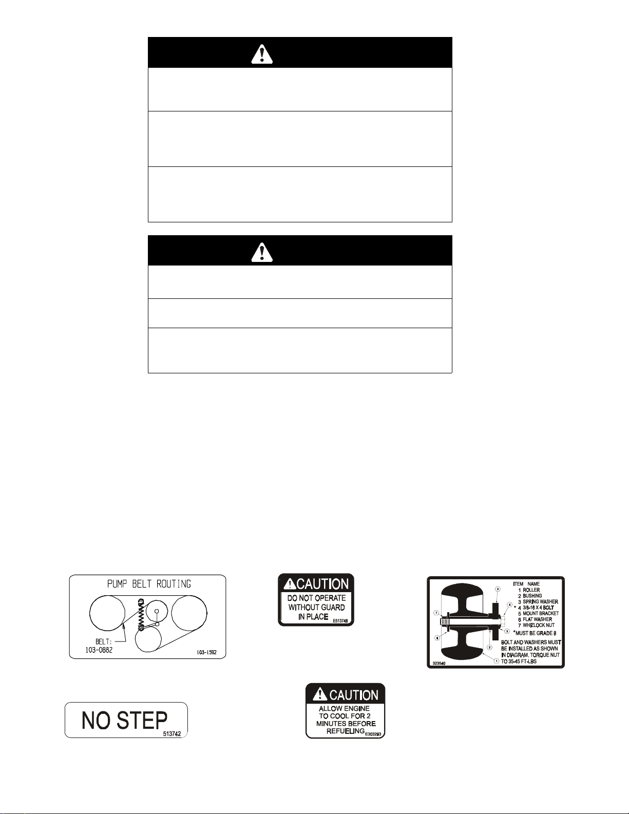
PART NO. 103-1592
LOCATION: Top of Right Engine Baffle
PART NO. 1-513748
LOCATIONS: Bottom Side of
Floorpan
PART NO. 1-323540
LOCATION: Left Rear Corner Top
of Mower Deck
PART NO. 1-513742
LOCATION: Top of Mower Deck Belt
Shields, Left and Right Sides
www.mymowerparts.com
31 HP Daihatsu Gas U nits Only
PART NO. 1-303293
LOCATION: On Top of Fuel Tanks
- 7 -
Page 13
For Exmark Mower Parts Call 606-678-9623 or 606-561-4983
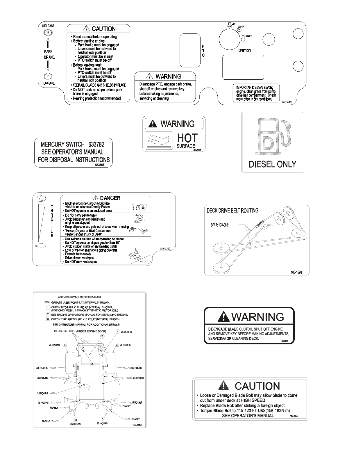
31 HP Daihatsu Gas U nits Only
PART NO. 103-0166
LOCATION: LH Side of Console
PART NO. 65-2690
LOCATION: Top of Radiator Trim
PART NO. 1-643401
LOCATION: On Tilt Switch
Plate, LH & RH Sides
27 HP Daihatsu Diesel Units Only
PART NO. 103-1636
LOCATION: Top of Fuel Tanks
PART NO. 103-0210
LOCATION: RH Side of Console
PART NO. 103-1593
LOCATION: Bottom Side of Floorpan
PART NO. 103-1596
LOCATION: Center Inside of the
Rear Bumper
PART NO. 1-633313
LOCATION: RH Side on Top
Front Mower Deck
PART NO. 103-1077
LOCATION: Top LH Side of Mower Deck
next to Stiffener
- 8 -
www.mymowerparts.com
Page 14
For Exmark Mower Parts Call 606-678-9623 or 606-561-4983
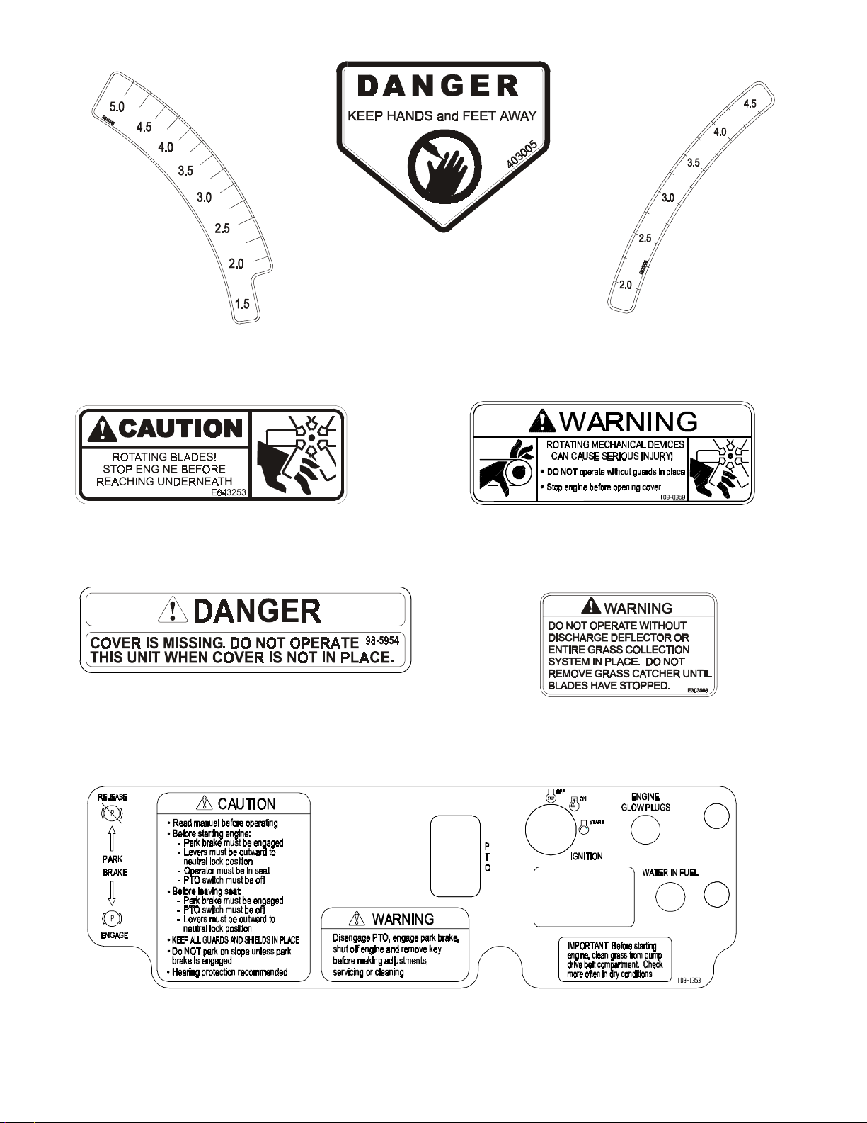
PART NO. 1-403005
LOCATION: Left and Right Corners
of Mower Deck
PART NO. 1-633345
LOCATION: RH Side of Cutting
Height Adjustment Plate
PART NO. 1-643253
LOCATION: LH and RH Sides of Radiator Mount Plate
PART NO. 98-5954
LOCATION: - Under LH and RH Belt Shields
- Radiator Fan Pump Idler Arm
PART NO. 1-633706
LOCATION: LH Side of Cutting
Height Adjustment Plate
PART NO. 103-0368
LOCATION: - Rubber Heat Shield Flap behind Seat
PART NO. 1-303508
LOCATION: RH Side on Top Rear of
Mower Deck
27 HP Daihatsu Diesel Units Only
PART NO. 103-1353
LOCATION: LH Side of Console
- 9 -
www.mymowerparts.com
Page 15
For Exmark Mower Parts Call 606-678-9623 or 606-561-4983
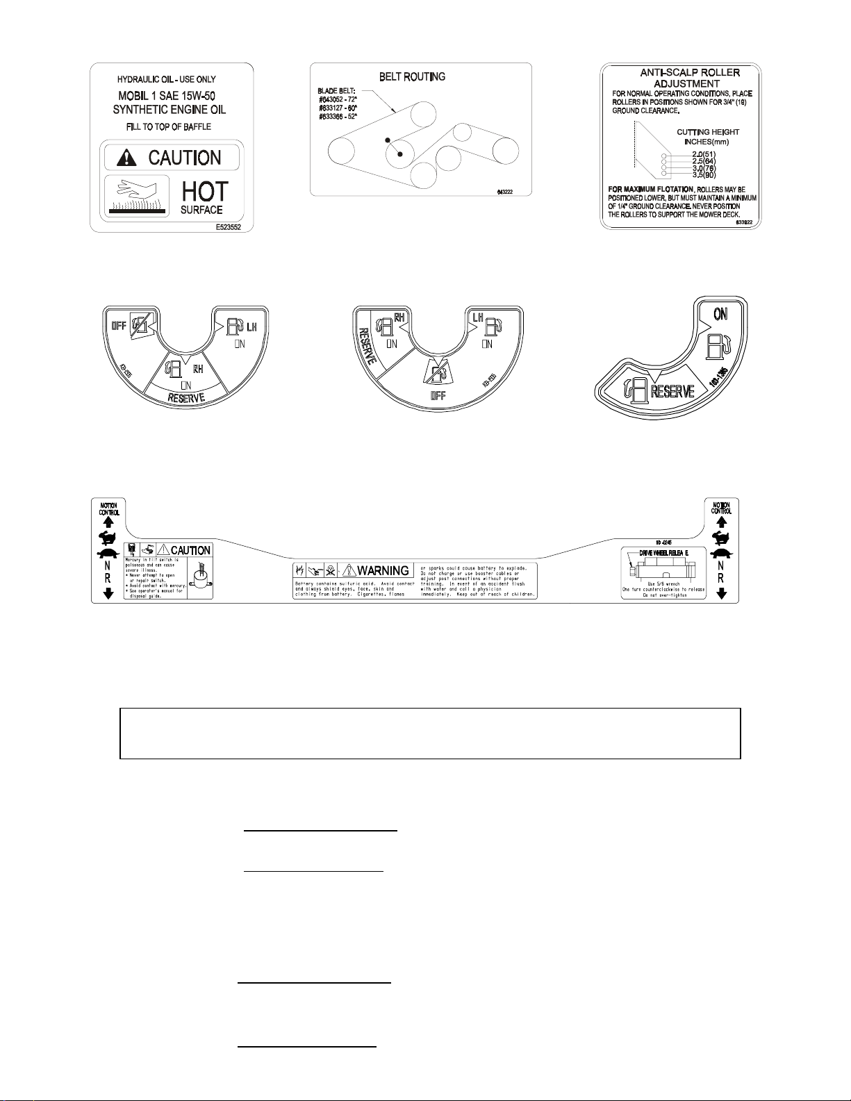
PART NO. 1-643222
LOCATION: Left of Center on Mower
PART NO. 1-523552
LOCATION: Top of Hydraulic
Reservoir
Deck, Under Floor Pan
PART NO. 1-633922
LOCATION: Front Center on Top
of Mower Deck
27 HP Daihatsu Diesel Units Only
PART NO. 103-1505
LOCATION: Left of Center on
Front of Console
PART NO. 103-0245
LOCATION: Top of console
2. SPECIFICATIONS
2.1 MODEL NUMBER:
Serial Nos. 260,000 and Higher
LZ27DD604; LZ27DD724; LZ31DG604; LZ31DG724
2.2 ENGINE:
2.2.1 Engine Specifications: See your Engine Owner’s Manual
2.2.2 RPM: 27 HP Daihatsu Diesel
Full Speed: 3850 RPM (No Load) Idle: 1750 RPM
31 HP Daihatsu Gas
Full Speed: 3850 RPM (No Load) Idle:1600 RPM
31 HP Daihatsu Gas U nits Only
PART NO. 103-1506
LOCATION: Left of Center on
Front of Console
PART NO. 103-1365
LOCATION: Right of Center on
Front of Console
2.3 FUEL SYSTEM
2.3.1 Capacity: 11.0 gal. (2 L.)
2.3.2 Type of Fuel:
27 HP Daihatsu Diesel: Diesel fuel, 40 cetane or higher
Note: Do not use kerosene or gasoline instead of diesel fuel.
31 HP Daihatsu Gas: Regular unleaded gasoline, 87 octane or higher
www.mymowerparts.com
Failure to observe this caution will damage the engine.
- 10 -
Page 16

For Exmark Mower Parts Call 606-678-9623 or 606-561-4983
2.3.3 Fuel Filter:
27 HP Daihatsu Diesel: Replaceable Canister -10 micron
Briggs & Stratton P/N 820311
31 HP Daihatsu Gas: In-line 15 micron
Briggs & Stratton P/N 498688
2.3.4 Fuel Shut-Off Valve: 1/4 turn increments
(Left t ank, “OFF”, Right tank – Gas Unit s)
(Left tank, Right tank/Reserve, “OFF” – Diesel Units)
Fuel Reserve Valve: 1/4 turn increment (Right tank, “Reserve”)
2.4 ELECTRICAL SYSTEM
2.4.1 Charging System: External Alternator
2.4.2 Charging Capacity: 40 Amps
2.4.3 Battery Type: BCI Group Size 26
2.4.4 Battery Voltage: 12 Volt
2.4.5 Polarity: Negative Ground
2.4.6 Fuses: One 40 amp and one 20 amp blade type
2.4.7 Safety Interlock System:
Blades must be disengaged, brake engaged, and motion control levers out
(neutral lock) to start engine. (It is not necessary for the operator to be in the
seat to start the engine.)
Operator must be in seat when Blades are engaged, brake is disengaged, or
motion control levers are moved in or engine will stop.
Engine will stop if either the left, the right, or both levers are moved from neutral
lock position while brake is engaged.
2.4.8 Tilt Switch: Shuts off the engine when the unit is tilted more than 60° from
horizontal.
2.5 COOLING SYSTEM
2.5.1 Fan: Hydraulic, continuous operation with engine running
2.5.2 Coolant Liquid: 50/50 mix of Dex-Cool © extended life antifreeze and water.
2.5.3 Coolant Capacity: 2 gallons (7.6 L)
2.6 OPERATOR CONTROLS
2.6.1 Steering and Motion Control:
Separate levers, on each side of the console, control speed and direction of
travel of the respective drive wheels.
Steering is controlled by varying the position of the levers relative to each other.
Moving motion control levers outward
NOTE: Motion control levers are adjustable to two heights.
2.6.2 Blade Engagement Switch: Engages electric clutch (to drive belts) which engage
mower blades.
2.6.3 Parking Brake Lever: Sets brakes.
2.6.4 Deck Height Adjustment Lever: Sets cutting height to desired position.
2.6.5 Deck Lift Assist Lever: Foot pedal that assists in raising the deck.
(in slots) locks the drive system in neutral.
2.7 SEAT
2.7.1 Type: Deluxe suspension seat with high back, low profile foam-in-place cushion
(dampened, adjustable spring suspension) and armrests.
- 11 -
www.mymowerparts.com
Page 17

For Exmark Mower Parts Call 606-678-9623 or 606-561-4983
2.7.2 Mounting: Hinged to tilt up for access to hydraulic pumps, battery and other
components. Held in tilted position with prop rod. Adjustable fore and aft seat track.
2.7.3 Armrests: Molded adjustable flip-up
2.7.4 Seat Safety Switch: Incorporated into the Safety Interlock System. Time delay
seat switch eliminates rough ground cut-outs.
2.8 HYDROSTATIC GROUND DRIVE SYSTEM
2.8.1 Hydrostatic Pumps: Two Hydro Gear BDP-21L variable displacement piston pumps.
2.8.2 Wheel Motors: Two Parker/Ross with 1 1/4” tapered shafts.
2.8.3 Hydraulic Oil Type: Synthetic Mobil 1 15W-50.
2.8.4 Hydraulic Oil Capacity: 4 qt. (3.8 L.)
2.8.5 Hydraulic Filter: Replaceable cartridge type.
P/N 103-1396: 10 microns, No bypass (Summer use above 32° F)
P/N 103-1574: 25 microns, No bypass (Winter use below 32° F)
2.8.6 Speeds: 0 - 11. 0 mph (17.7 km/hr) forward.
0 – 7.0 mph (11.3 km/hr) reverse.
2.8.7 Drive wheel release valves allow machine to be moved when engine is not
running.
armrests.
2.9 TIRES AND WHEELS
2.9.1 Tires Drive Front Caster
Qty:..........................................2 .....................................2
Ply:...........................................4 .....................................4
Infl:................................13 psi (90 kPa) ............... 13 psi (90 kPa)
Size:................................24 x 12.0-12.....................13 x 6.50-6
Tread:............................. “Turf Master”.......................Smooth
2.10 CUTTING DECK
2.10.1 Cutting Width: 72 in. (182.9 cm)
60 in. (152.4 cm)
2.10.2 Discharge: Side
2.10.3 Blade Size: (3 each) w/60” Deck 20.5 in. (52.1 cm)
w/72” Deck 24.5 in. (62.2 cm)
2.10.4 Blade Spindles: Solid steel spindles with 1” I.D. bearings.
2.10.5 Deck Drive: Electric clutch mounted on horizontal engine shaft. 2 – “A” Section
belts (with self-tensioning idlers) from electric clutch to transfer shaft mounted on
deck.
Blades are driven by one “B” Section belt (w/self-tensioning idler) from transfer
shaft on deck to blade spindles.
2.10.6 Deck: Full floating deck is attached to out-front support frame. Six anti-scalp
rollers provide maximum turf protection. Dual deck support shafts add to the
stability of the deck. Deck design allows for bagging, mulching or side discharge.
2.10.7 Deck Depth: 5.5” (14.0 cm)
2.10.8 Cutting Height Adjustment: an extra-long cushioned lever is used to adjust the
cutting height from 1 1/2” (3.8 cm) to 5” (10.2 cm.) in 1/4”(6.4 mm) increments
for. The cutting height adjustment handle has a transport position and all
adjustments can be made while the operator remains seated. Units also have a
foot operated deck lift assist lever to aid in raising the deck.
2.10.9 Mulching Kit: Optional.
- 12 -
www.mymowerparts.com
Page 18

For Exmark Mower Parts Call 606-678-9623 or 606-561-4983
2.11 DIMENSIONS
2.11.1 Overall Width:
without deck deflector up deflector down
60” Deck 54.5 in. (138.4 cm) 61.4 in. (156.0 cm) 72.2” (179.3cm)
72” Deck 58.5 in. (148.6 cm) 73.2 in. (185.9 cm) 84.3” (212.8cm)
2.11.2 Overall Length: 60” decks – 82.2 in. (208.8 cm)
72” decks – 85.96. (217.2cm)
2.11.3 Overall Height: 50 in. (127.0 cm) (height will vary slight ly depending on seat setting)
2.11.4 Tread Width: (center to center of tires, widthwise)
Drive wheels: w/60” Deck – 42.8 in. (108.7 cm)
w/72” Deck – 46.8 in. (118.9 cm)
Casters: w/60” Deck – 38.9 in. (98.8 cm)
w/72” Deck – 47.6 in. (120.9 cm)
2.11.5 Wheel Base: (center of caster tire to center of drive tire)
w/60” Decks – 54.0 in. (137.2 cm)
w/72” Deck – 56.8 in. (144.3 cm)
2.11.6 Curb Weight
27 HP Daihatsu Diesel: w/60” Deck – 1565 lbs. (709 kg)
w/72” Deck – 1583 lbs. (718 kg)
31 HP Daihatsu Gas: w/60” Deck – 1541 lbs. (699 kg)
w/72” Deck – 1542 lbs. (699 kg)
2.12 TORQUE REQUIREMENTS
Bolt Location Torque
Cutter Housing Spindle Nut............................................ 75-80 ft-lbs. (102-109 N-m)
Blade Mounting Bolt....................................................... 115-120 ft-lbs. (156-163 N-m)
Engine Deck/Front Frame Mount....................................30-35 ft-lbs. (41-48 N-m)
Anti-Scalp Roller Bolts....................................................40-45 ft-lbs. (54-61 N-m)
Starter Mounting Bolts (M10).......................................... 22-27 ft-lbs. (30-37 N-m)
Water Separator Mounting Bolts (M8) Diesel only.......... 11-14 ft-lbs. (15-19 N-m)
Hydraulic Oil Filter Head Mounting Bolts (M6)................ 60-72 in-lbs. (7-8 N-m)
Wheel Lug Nuts.............................................................. 90-95 ft-lbs. (122-129 N-m)
Wheel Motor Mounting Bolts .......................................... 72-77 ft-lbs. (98-104 N-m)
Wheel Hub Slotted Nut................................................... minimum125 ft-lbs. (169 N-m)
3. ASSEMBLY INSTRUCTIONS
3.1 UNCRATE MOWER
3.2 SERVICE BATTERY.
WARNING: Battery posts, terminals, and related accessories contain lead compounds,
chemicals known to the State of California to cause cancer and reproductive harm. Wash
hands after handling.
The machine is shipped with a filled lead acid battery.
3.2.1 Tilt seat up to gain access to the battery.
- 13 -
www.mymowerparts.com
Page 19

For Exmark Mower Parts Call 606-678-9623 or 606-561-4983
DANGER
POTENTIAL HAZARD
♦ Charging the battery may produce explosive gases
WHAT CAN HAPPEN
♦ Battery gases can explode causing serious injury.
HOW TO AVOID THE HAZARD
♦ Keep sparks, flames, or cigarettes away from battery.
♦ Ventilate when charging or using battery in an
enclosed space.
♦ Make sure venting path of battery is always open once
battery is filled with acid.
3.2.2 Check the voltage of the battery with a digital voltmeter. Locate the voltage reading
of the battery in the table below and charge the battery for the recommended time
interval to bring the charge up to a full charge of 12.6 volts or greater.
IMPORTANT: When charging the battery, make sure the negative battery
cables are disconnected and the battery charger has an output of 16 volts and 7
amps or less to avoid damaging the battery (see chart below for recommended
charger settings).
Voltage
Reading
12.6 or greater 100% 16 volts/7 amps No Charging Required
12.4 – 12.6 75 – 100% 16 volts/7 amps 30 Minutes
12.2 – 12.4 50 – 75% 16 volts/7 amps 1 Hour
12.0 – 12.2 25 – 50% 14.4 volts/4 amps 2 Hours
11.7 – 12.0 0 – 25% 14.4 volts/4 amps 3 Hours
11.7 or less 0% 14.4 volts/2 amps 6 Hours or More
Percent
Charge
Maximum
Charger Settings
Charging Interval
CAUTION
POTENTIAL HAZARD
♦ If the ignition is in the “ON” position there is potential
for sparks and engagement of components.
WHAT CAN HAPPEN
♦ Sparks could cause an explosion or moving parts
could accidentally engage causing personal injury.
HOW TO AVOID THE HAZARD
♦ Be sure ignition switch is in the “OFF” position before
charging the battery.
3.2.3 Connect the negative battery cables.
NOTE: If the positive cable is also disconnected, connect the positive (red)
cable to the positive terminal on the battery first, then connect the negative
(black) cable to the negative terminal. Slip insulator boot over the positive
terminal.
NOTE: If time does not permit charging the battery, or if charging equipment is
not available, connect the negative battery cables and run the vehicle
continuously for 20 to 30 minutes to sufficiently charge the battery.
- 14 -
www.mymowerparts.com
Page 20

For Exmark Mower Parts Call 606-678-9623 or 606-561-4983
3.3 INSTALL DRIVE WHEELS
3.3.1 Mount drive wheels with the valve stem to the outside of the unit. Secure using
four (4) 1/2-20 wheel nuts (installed on studs in hubs) for each wheel. Torque to
95 ft-lbs (128 N!M).
.
3.4 CHECK TIRE PRESSURE.
3.4.1 Check tire pressure in caster and drive tires. Proper inflation pressure for all four
(4) tires is 13 psi (90 kPa). Adjust if necessary.
3.5 INSTALL SEAT.
3.5.1 The seat base frame with adjustable tracks and seat
retaining rod are already attached to the unit. Remove
the suspension seat from front of crate and discard the
hardware. Position the seat with the holes on the
studs in the adjustable tracks; be sure the left and
right tracks are aligned (See Fig.1). Loosen the vinyl
curtain frame at the rear by pushing down and ahead
out of the hole. Secure the seat with four (4) 5/16
whizlock nuts. Reattach the vinyl curtain frame.
Connect the terminal at the end of the wire tied to
the seat frame to the switch in the bottom of the seat.
SEAT INSTALLATION
3.6 INSTALL FOOT LIFT ASSIST
a) Remove the lift assist lever from the rear deck lift arm or the seat base frame (the lift
assist is fastened in this position for shipping only) and attach to the front deck lift
lever as shown in Fig. 2.
FIG. 1
SUSPENSION
FIG. 2
LEVER ALIGNMENT
3.7 INSTALL MOTION CONTROL LEVERS.
3.7.1 Loosen and remove the two (2) 3/8”x1” bolts and spring disk washers which
attach the motion control levers to the control arm shafts for shipping and the two
(2) 3/8” x 1” bolts and spring disk washers which are screwed into the control arm
shafts.
- 15 -
www.mymowerparts.com
Page 21

For Exmark Mower Parts Call 606-678-9623 or 606-561-4983
a) Install the left motion control lever onto the control arm shaft (See Fig.4) on the
left side of the console. Place the lever (with the mounting plate towards the
rear) on the outside of the control arm shaft and secure with the bolts and
washers. Position the lever so the bolts are in the center of the slots on the
lever mounting plate and tighten until snug. Repeat on opposite side of unit.
NOTE: There are two lever height options available. Place the levers in the top
two holes to increase height of the levers, or the bottom two holes to decrease
the height of the levers.
If the levers do not align with each other, when in the neutral position, (See
Fig. 5) loosen the hardware and make the appropriate adjustment by sliding/tilting
the lever(s) forward or backward until properly aligned and tighten hardware.
MOTION
CONTROL
LEVER
MOUNT PLATE TO
THE REAR & OUTSIDE
OF ARM SHAFT
LEVERS IN
ALIGNMENT
FIG. 4 FIG. 5
CONTROL ARM SHAFT LEVER ALIGNMENT
b) If the ends of the levers hit against each other, while in the drive position
(levers rotated in as far as possible), make adjustments by moving the levers
outwards to the neutral lock position and carefully bend them outward. Move
them back to the drive position and check for clearance, repeat if necessary.
3.8 POSITION DISCHARGE CHUTE.
3. 8.1 Loosen two (2) 5/16” nyloc nuts attaching discharge chute. Lower the discharge
chute into position. Retighten nyloc nuts until chute is snug but can pivot freely.
3.9 SERVICE ENGINE.
Refer to Engine Owner’s Manual
3.10 SERVICE ENGINE COOLANT
Machine is shipped filled with engine coolant.
POTENTIAL HAZARD
♦ Engine coolant is hot and pressurized.
♦ Radiator and surrounding parts are hot.
WHAT CAN HAPPEN
♦ Spray or steam from hot, pressurized liquid in the
engine cooling system or touching a hot radiator may
cause severe burns.
WARNING
HOW TO AVOID THE HAZARD
♦ Allow the engine to cool completely before removing
the radiator cap or servicing any component of the
cooling system.
- 16 -
www.mymowerparts.com
Page 22

For Exmark Mower Parts Call 606-678-9623 or 606-561-4983
CAUTION
POTENTIAL HAZARD
♦ Engine coolant is toxic.
WHAT CAN HAPPEN
♦ Swallowing coolant can cause poisoning.
HOW TO AVOID THE HAZARD
♦ Do not swallow
♦ Keep out of reach of children and pets.
With machine on level surface and with cool engine, remove radiator cap (under
hood) and add a 50/50 mix of water and Dex-Cool© extended life coolant until liquid
level is as high as possible without overflowing. Reinstall radiator cap, making sure
that the cap is completely seated by pressing down firmly while turning until the cap
stops. Add 50/50 coolant mix to overflow bottle on the left side of the engine as
required to bring the level up to the indicator line on the bottle.
NOTE: Units should only be filled with Dex-Cool© extended life coolant. DexCool© can be identified by its orange color.
3.11 SERVICE HYDRAULIC OIL
The machine is shipped with hydraulic oil filled to the top the baffle in the
reservoir. Run the machine for approximately 15 minutes to allow any extra air to
purge out of the hydraulic system. Check hydraulic reservoir and if necessary fill
the reservoir to the appropriate level with Mobil 1 15W-50 synthetic motor oil.
4. OPERATION INSTRUCTIONS
4.1 CONTROLS
4.1.1 Familiarize yourself with all contr ols before operating the mower.
4.1.2 Motion Control Levers: Located on each side of the console. The left lever
controls the flow of hydraulic oil from the left hydrostatic pump to the left drive
wheel motor. The right lever controls the flow of hydraulic oil from the right
hydrostatic pump to the right drive wheel motor.
IMPORTANT: To begin movement (forward or backward) the operator must
be in the seat, the brake lever must be disengaged (pushed down) before
the motion control levers can be moved in or the engine will kill.
When levers are centered in the T-slot the drive system is in the neutral position.
With levers moved out in the T-slot the drive system is in the neutral lock
position (See Fig. 6).
FIG. 6
MOTION CONTROL POSITIONS
By moving both levers an equal amount forward or back from the neutral position
the machine can be caused to move forward or backward in a straight line.
Movement of the left lever forward will cause the left drive wheel to rotate in a
forward direction. Movement of the right lever forward will cause the right
- 17 -
www.mymowerparts.com
Page 23

For Exmark Mower Parts Call 606-678-9623 or 606-561-4983
drive wheel to rotate in a forward direction. To stop forward travel, pull the
levers back to the neutral position.
To turn left while moving forward, move the left lever back toward neutral to
slow the left drive wheel.
To turn right while moving forward, move the right lever back toward neutral to
slow the right drive wheel.
To make a zero turn to the left, pull the left lever back beyond neutral while
holding the right lever slightly ahead of neutral.
To make a zero turn to the right, pull the right lever back beyond neutral while
holding the left lever slightly ahead of neutral.
Pulling the levers back from the neutral position will cause the respective drive
wheels to rotate in a reverse direction (spring tension can be felt when moving
into reverse from neutral).
To turn to the left while backing, move the left lever forward toward neutral. To
turn to the right while backing, move the right lever forward toward neutral.
POTENTIAL HAZARD
♦ Machine can spin very rapidly by positioning one lever
too much ahead of the other.
WHAT CAN HAPPEN
♦ Operator may lose control of the machine, which may
cause damage to the machine or injury.
HOW TO AVOID THE HAZARD
♦ Use caution when making turns.
♦ Slow the machine down before making sharp turns.
4.1.3 Blade Engagement Switch: Located just left of center on the console (left side of
ignition switch). Switch must be pulled out to the “ROTATE” position to engage
the blades. Switch is pushed in to the “STOP” position to stop the blades.
4.1.4 Choke Control (31 HP Daihatsu Gas Units Only): Located at lower center of console
(right side of ignition switch). Choke is used to aid in starting a cold engine. The
choke control i s pulled out to be in the “ON” position and pushed in to be in the
“OFF” position. DO NOT run a warm engine with choke in the “ON” position.
4.1.5 Throttle Control: Located on console just right of center.
Throttle is used to control engine speed. Moving throttle lever forward will increase
engine speed and moving throttle lever to the rear will decrease engine speed.
4.1.6 Brake Lever: Located on left side of unit, just to the front of the console. The
brake lever engages a parking brake on the drive wheels.
Pull the lever up and rearward to engage the brake.
Push the lever forward and down to disengage the brake.
When parking on a steep slope, the wheels must be chocked or blocked in
addition to the brake being engaged. The unit must be tied down and brake
engaged when transporting.
4.1.7 Ignition Switch: Located on the lower center of console.
The ignition switch is used to start and stop the engine. The switch has three
positions “OFF”, “ON” and “START”. Insert the key into switch and rotate
clockwise to the “ON” position. Rotate clockwise to the next position to engage
the starter (key must be held against spring pressure in this position).
CAUTION
- 18 -
www.mymowerparts.com
Page 24

For Exmark Mower Parts Call 606-678-9623 or 606-561-4983
NOTE: On 27 HP Daihatsu Diesel units a glow plug light, located to the right of the
ignition switch, will illuminate when the switch is turned to the “ON” position. The
glow plug light indicates the glow plugs are preheating the combustion chamber.
Wait until the light goes out before rotating the key to the “START” position.
Brake must be engaged, motion control levers out (neutral lock position)
and blade engagement switch “OFF” to start engine. (It is not necessary for
the operator to be in the seat to start the engine.)
4.1.8 Hour Meter: Located on center of console. The hour meter is to record the
number of hours that the engine has run. If the ignition switch is left “ON” without
engine running, the hour meter will continue to run.
4.1.9 Fuel Shut-Off Valve: Located left of center on front of console. The fuel shut-off
valve is used to shut off the fuel when the machine will not be used for a few days,
during transport to and from the job site, and when parked inside a building. The
valve has three positions. Each position is made in 1/4 turn increments.
NOTE: The positions for the 27 HP Daihatsu Diesel are different than the positions
for the 31 HP Daihatsu Gas. Reference the table below for the correct locations.
FUEL FLOW
“OFF” DOWN RIGHT
RIGHT TANK “ON” RIGHT DOWN
LEFT TANK “ON” LEFT LEFT
4.1.10 Reserve Fuel Valve: Located right of center on front of console. The reserve fuel
valve is used to release reserve fuel from the right tank when both the left and right
fuel tanks have become empty. The valve has two positions. Each position is
made in 1/4 turn increments. Reference the table below for the correct locations.
FUEL FLOW
RIGHT TANK “ON” LEFT
RESERVE FUEL DOW N
Return the valve the “Right Tank ON” position after refueling the right tank.
Note: For 27 HP Daihatsu Diesel units, the operator must prime the fuel system
when the fuel tanks have gone empty. The primer pump is the gold button located
under the seat next to the console in the front left-hand corner. To prime the
system, turn the reserve fuel valve to the “Reserve” position and push down on the
primer pump until the tension becomes firm (approximately 10-15 pushes).
4.1.11 Drive Wheel Release Valves: Located on the top right front corner of hydrostatic
pumps. Drive wheel release valves are used to release the hydrostatic drive
system to allow the machine to be pushed without the engine running. Tilt seat
up to gain access to pumps.
With a 5/8 wrench, turn both valves one turn counter-clockwise to release drive system.
Turn clockwise to reset system. DO NOT overtighten. DO NOT tow machine.
4.1.11 Coolant Temperature Gauge: Located at the front of the right fuel tank. The
coolant temperature gauge monitors the temperature of the engine coolant. The
engine will overheat if the coolant temperature becomes too high.
4.1.12 Voltmeter: Located next to the Coolant Temperature Gauge at the front of the
right fuel tank. The voltmeter measures the voltage output of the alternator.
Both high and low voltages will potentially damage the battery.
4.1.13 Water in Fuel Light (27 HP Daihatsu Diesel Only): Located on the console to the
right of the hour meter. An illuminated water in fuel light signals water in the
diesel fuel. Water should be drained from the fuel filter if the light is on.
27 HP Daihatsu Diesel 31 HP Daihatsu Gas
VALVE POSITION
VALVE POSITION
ALL LAZER XP UNITS
- 19 -
www.mymowerparts.com
Page 25

For Exmark Mower Parts Call 606-678-9623 or 606-561-4983
IMPORTANT: Water or other contaminants in fuel can severely damage fuel
pump and/or other engine components.
4.1.14 Glow Plug Light (27 HP Daihatsu Diesel Only): Located on the console to the
right of the ignition switch. The glow plug light comes on when the ignition switch
is turned to the ON position. The glow plug light indicates the glow plugs are
preheating the combustion chamber. Wait for the glow plug light to go out before
starting the engine.
4.1.15 Warning Buzzer: Located behind the seat on the left hand side of the engine air
deflector. The buzzer is a warning signal for the following circumstances:
a) When the engine is not running and the ignition switch is turned to the ON
position, the buzzer emits intermittent beeps. The intermittent beeps remind
the user that the switch is ON and the hourmeter is running. A switch left ON
could also drain the battery.
b) When the engine is running and the buzzer emits a continuous beep, the
buzzer is warning the user that the engine is overheating. Perform the
following steps.
1. Disengage the mower blades, and idle down the engine.
2. Look at the temperature gauge to determine if temperature
continues to increase. If it does, turn the unit off and allow the
engine and engine components to cool.
3. Check the coolant level. If necessary fill with coolant as described
in Section 5.1.2.
4. Remove any debris on or around the radiator that may restrict
airflow.
c) When the engine is running and the buzzer emits intermittent beeps, the
buzzer is warning the user that the engine oil pressure is low. Perform the
following steps.
1. Turn the unit off, allow the engine and engine components to cool.
2. Check the oil level and fill, if necessary, as described in Section
5.1.1.
3. Check for oil leaking from engine. If the engine is leaking, see
Engine Service Dealer.
4.2 PRE-START
4.2.1 Fill fuel tank s.
For 31 HP Daihatsu Gas Units:
For best results use only clean, fresh regular grade unleaded gasoline with an
octane rating of 87 or higher. Regular grade leaded gasoline may also be used;
however, combustion chamber and cylinder head will require more frequent
service. See Engine Owner's Manual.
For 27 HP Daihatsu Diesel Units:
For best results use only clean, fresh diesel fuel, with a cetane rating of 40 higher.
NOTE: Do not use kerosene or gasoline instead of diesel fuel. Failure to
observe this caution will damage the engine.
For All Units:
DO NOT add oil to gasoline.
DO NOT overfill fuel tank. Never fill the fuel tank so that the fuel level rises
above a level that is 1/2” below the bottom of the filler neck to allow for fuel
expansion and prevent fuel spillage.
4.2.2 Make sure you understand the controls, their locations, their functions, and their
safety requirements.
4.2.3 Refer to Maintenance, Section 5, and perform all the necessary inspection and
maintenance steps.
- 20 -
www.mymowerparts.com
Page 26

For Exmark Mower Parts Call 606-678-9623 or 606-561-4983
4.3 MOWING
4.3.1 Open fuel shut-off valve (left or right tank).
4.3.2 Starting Engine:
a) Brake must be engaged, motion control levers out (neutral lock
position) and blade engagement switch “OFF” to start engine. (It is
not necessary for the operator to be in the seat to start the engine.)
For 31 HP Daihatsu Gas Units:
b) On a warm engine, place the throttle midway between the “SLOW” and
“FAST” positions and leave the choke in the “OFF” position.
On a cold engine, place the throttle in the “FAST” position and pull the
choke to the “ON” position.
c) Turn ignition switch to the “start” position. Release the switch as soon as
the engine starts.
IMPORTANT: DO NOT crank the engine continuously for more then
ten (10) seconds at a time. If the engine does not start, allow a 60
second cool-down period between starting attempts. Failure to follow
these guidelines can burn out the starter motor.
d) After starting a cold engine, gradually return choke to the “OFF” position as
the engine warms up.
For 27 HP Daihatsu Diesel Units:
b) On a warm engine, place the throttle in the “SLOW” position.
On a cold engine (below 14° F (-10° C)), place the throttle in the “FAST”
position.
Note: Do not use fuel left over from summer.
c) Turn the ignit ion switch to the “ON” position. The glow plug light will turn
on. Wait for the glow plug light to turn off and turn the ignition switch to the
“START” position. Release the switch as soon as the engine starts.
IMPORTANT: DO NOT crank the engine continuously for more then
ten (10) seconds at a time. If the engine does not start, allow a 60
second cool-down period between starting attempts. Failure to follow
these guidelines can burn out the starter motor.
c) Move the throttle t o the “SLOW” (if in “FAST”) and let the engine warm up a
few minutes befo re moving the thro ttle to the “FAST” position.
4.3.3 Engaging Electric Blade Clut c h: The electric blade clutch push-pull switch
engages the cutting blades. Be sure that all persons are clear of the mower
deck and discharge area before engaging cutting blades.
IMPORTANT: Operator must be in seat before the blades can be engaged.
Set throttle to "midway" position. Pull outward on the switch to the “ROTATE”
position. Accelerate to full throttle to begin mowing.
4.3.4 Stopping Electric Blade Clutch: Set thrott le to the “idle” position. Push in on the
switch to the “STOP” position stopping the cutting blades.
4.3.5 Stopping Engine:
a) Bring unit to a full stop. Disengage the cutting blades, move motion
control levers out to the neutral loc k position and set parking brake.
b) Before stopping the engine, move the throttle control to the “SLOW”
position. Keep on running at idle for a short time, (approximately one
minute) then stop the engine.
NOTE: For 31 HP Daihatsu Gas Units - Do not move the choke to the “ON”
position to stop the engine. Backfire or engine damage may occur.
- 21 -
www.mymowerparts.com
Page 27

For Exmark Mower Parts Call 606-678-9623 or 606-561-4983
c) Rotate ignit ion switch to “OFF” position. Remove the key to prevent
children or other unauthorized persons from starting engine.
d) Close fuel shut-off valve when machine will not be used for a few days,
when transporting, and when the unit is parked inside a building.
4.4 TRANSPORTING
4.4.1 Transporting a Unit: Use a heavy-duty trailer or truck to transport the machine. Lock
brake and block wheels. Securely fasten the machine to the trailer or truck with
straps, chains, cable, or ropes. Be sure that the trailer or truck has all necessary
lighting and marking as required by law. Secure a trailer with a safety chain.
POTENTIAL HAZARD
♦ This unit does not have proper turn signals, lights,
reflective markings, or a slow moving vehicle emblem.
These items are required to drive on a public street or
roadway.
WHAT CAN HAPPEN
♦ Driving on a street or roadway without such equipment
is dangerous and can lead to accidents causing
personal injury.
♦ Driving on a street or roadway without such equipment
may also be a violation of State laws and the operator
may be subject to traffic tickets and/or fines.
HOW TO AVOID THE HAZARD
♦ Do not drive a unit on a public street or roadway.
POTENTIAL HAZARD
♦ Loading a unit on a trailer or truck increases the
possibility of backward tip-over.
WHAT CAN HAPPEN
♦ Backward tip-over of the unit could cause serious
injury or death.
HOW TO AVOID THE HAZARD
♦ Use extreme caution when operating a unit on a ramp.
♦ Use only a single, full width ramp; DO NOT use
individual ramps for each side of the unit.
♦ If individual ramps must be used, use enough ramps to
create an unbroken ramp surface wider than the unit.
♦ DO NOT exceed a 15° angle between ramp and
ground or between ramp and trailer or truck.
♦ Avoid sudden acceleration while driving unit up a ramp
to avoid tipping backward.
♦ Avoid sudden deceleration while backing unit down a
ramp to avoid tipping backward.
CAUTION
WARNING
- 22 -
www.mymowerparts.com
Page 28

For Exmark Mower Parts Call 606-678-9623 or 606-561-4983
POTENTIAL HAZARD
♦ Gasoline vapor can collect inside enclosed trailers and
may be ignited by electrical sparks or hot
engine/exhaust components.
WHAT CAN HAPPEN
♦ Explosion and fire may occur, resulting in property
damage, personal injury and/or death.
HOW TO AVOID THE HAZARD
♦ Provide adequate ventilation of any enclosed trailer to
prevent build up of gasoline vapors, especially at floor
level.
♦ Never refuel equipment inside an enclosed trailer.
♦ Be sure all fuel tanks and gasoline storage containers
have proper caps installed to prevent spillage and
minimize vapor escaping into the trailer.
♦ Do not place any equipment that is leaking gasoline in
an enclosed trailer.
4.4.2 Loading a Unit: Use extreme caution when loading units on trailers or trucks.
One full width ramp that is wide enough to extend beyond the rear tires is
recommended instead of individual ramps for each side of the unit. The lower
rear section of the tractor frame extends back between the rear wheels and
serves as a stop for tipping backward. Having a full width ramp provides a
surface for the frame members to contact if the unit starts to tip backward. If it is
not possible to use one full width ramp, use enough individual ramps to simulate
a full width continuous ramp.
Ramp should be long enough so that the angles between the ramp and the
ground and the ramp and the trailer or truck do not exceed 15°. A steeper angle
may cause mower deck components to get caught as the unit moves from ramp
to trailer or truck. Steeper angles may also cause the unit to tip backward. If
loading on or near a slope, position the trailer or truck so it is on the down side of
the slope and the ramp extends up the slope. This will minimize the ramp angle.
The trailer or truck should be as level as possible.
DO NOT attempt to turn the unit while on the ramp, you may lose control and
drive off the side.
Avoid sudden acceleration when driving up a ramp and sudden deceleration
when backing down a ramp. Both maneuvers can cause the unit to tip backward.
WARNING
5. MAINTENANCE & ADJUSTMENTS
5.1 PERIODIC MAINTENANCE
5.1.1 Check engine oil level:
Service Interval: Daily
a) Make sure engine is stopped and on a level surface.
b) Check with engine cold.
c) Clean area around dipstick. Remove dipstick and wipe oil off. Reinsert the
dipstick and push it all the way down into the tube. Remove the dipstick
and read the oil level.
d) If the oil level is low, wipe off the area around the oil fill cap, remove cap
and fill to the “F” mark on the dipstick. Use oil as specified in Engine
Owner’s Manual. DO NOT overfill.
www.mymowerparts.com
- 23 -
Page 29

For Exmark Mower Parts Call 606-678-9623 or 606-561-4983
IMPORTANT: DO NOT operate the engine with the oil level below the “L”
mark on the dipstick, or over the “F” mark.
5.1.2 Check engine coolant level
Service Interval: Daily
a) Make sure engine is stopped and machine is positioned on a level surface.
b) Tilt seat up and tilt hood forward to gain access to the cooling area.
c) Check with engine cold.
d) View coolant level in overflow bottle on the left side of the engine. Coolant
level should be at the indicator line on the overflow bottle.
e) If the coolant level is low, remove the cap to the overflow bottle and fill to
the indicator line. Use coolant specified in Section 2.5.2.
NOTE: Units should only be filled with Dex-Cool© extended life coolant. DexCool© extended life coolant can be identified by its orange color.
POTENTIAL HAZARD
♦ Engine coolant is hot and pressurized.
♦ Radiator and surrounding parts are hot.
WHAT CAN HAPPEN
♦ Spray or steam from hot, pressurized liquid in the
engine cooling system or touching a hot radiator may
cause severe burns.
HOW TO AVOID THE HAZARD
♦ Allow the engine to cool completely before removing
the radiator cap or servicing any component of the
cooling system.
POTENTIAL HAZARD
♦ Engine coolant is toxic.
WHAT CAN HAPPEN
♦ Swallowing coolant can cause poisoning.
HOW TO AVOID THE HAZARD
♦ Do not swallow
♦ Keep out of reach of children and pets.
WARNING
CAUTION
5.1.3 Check battery charge:
Service Interval: Monthly
a) Check the voltage of the battery with a digital voltmeter. Locate the voltage
reading of the battery in the table below and charge the battery for the
recommended time interval to bring the charge up to a full charge of 12.6
volts or greater.
IMPORTANT: When charging the battery, make sure the negative battery
cables are disconnected and the battery charger has an output of 16 volts
and 7 amps or less to avoid damaging the battery (see chart below for
recommended charger settings).
www.mymowerparts.com
- 24 -
Page 30

For Exmark Mower Parts Call 606-678-9623 or 606-561-4983
Voltage
Reading
12.6 or greater 100% 16 volts/7 amps No Charging Required
12.4 – 12.6 75 – 100% 16 volts/7 amps 30 Minutes
12.2 – 12.4 50 – 75% 16 volts/7 amps 1 Hour
12.0 – 12.2 25 – 50% 14.4 volts/4 amps 2 Hours
11.7 – 12.0 0 – 25% 14.4 volts/4 amps 3 Hours
11.7 or less 0% 14.4 volts/2 amps 6 Hours or More
5.1.4 Clean engine cooling system:
a) Wipe debris from screen in engine cover. Rotate engine cover forward and
wipe debris from radiator core as required. Inspect seals in engine cover
and replace as necessary.
5.1.5 Clean grass build-up under deck.
a) Stop engine and remove key.
b) Raise deck to the transport (5” cutting height) position. Lift the front of unit
and support unit using jack stands or equivalent support.
Percent
Charge
Service Interval: Daily or more often in dry conditions
Service Interval: Daily
Maximum
Charger Settings
Charging Interval
POTENTIAL HAZARD
♦ Raising the mower deck for service or maintenance
relying solely on mechanical or hydraulic jacks could
be dangerous.
WHAT CAN HAPPEN
♦ The mechanical or hydraulic jacks may not be enough
support or may misfunction allowing the unit to fall,
which could cause injury.
HOW TO AVOID THE HAZARD
♦ DO NOT rely solely on mechanical or hydraulic jacks
for support. Use adequate jack stands or equivalent
support.
c) Clean out any grass build-up from underside of deck and in discharge chute.
5.1.6 Check mower blades.
a) Stop engine and remove key.
b) Lift deck and secure in raised position as stated in Section 5.1.5.
c) Inspect blades and sharpen or replace as required.
d) Re-install the blades (if they were removed) by placing a block of wood
between the front or rear baffles and the blade then torquing the blade bolts
to 115-120 ft-lbs. (156-13 N-m). Be sure the spring disk washer cone is
installed toward the bolt head (See Figure 7).
CAUTION
Service Interval: Daily
- 25 -
www.mymowerparts.com
Page 31

For Exmark Mower Parts Call 606-678-9623 or 606-561-4983
CAUTION
POTENTIAL HAZARD
♦ Operating a mower deck with loose or weakened
blade bolts can be dangerous.
WHAT CAN HAPPEN
♦ A loose or weakened blade bolt could allow a blade
rotating at a high speed to come out from under the
deck, causing serious injury or property damage.
HOW TO AVOID THE HAZARD
♦ Replace the blade bolt after striking a foreign object.
(Use only Exmark replacement parts PN 103-1026 –
blade bolt and PN 103-0865 – spring disk washer).
♦ DO NOT lubricate the threads of the bolt or spindle
before assembly.
♦ Torque the blade bolt to 115-120 ft-lbs. (156-13 N-m).
BLADE BOLT INSTALLATION
5.1.7 Check safety interlock system.
Service Interval: Daily
a) Check starting circuit. Starter should crank with, parking brake engaged,
cutting blades disengaged and motion control levers moved out in the neutra l
lock position. The operator does not need to be in the seat to start the engine.
Try to start with operator in seat, parking brake disengaged, blades
disengaged and motion control levers in the neutral lock position - starter
must not crank.
Try to start with operator in seat, parking brake engaged, blades engaged
and motion control levers in the neutral lock position - starter must not
crank.
Try to start with operator in seat, parking brake engaged, blades
disengaged, and the left motion control lever in, starter must not
crank, repeat again with the right lever in, then with both levers in -
starter must not crank.
b) Check the kill circuits. Run engine at one-third throttle, disengage parking
brake and raise off of seat (but do not get off of machine) engine must
stop after approx. 1/2 second has elapsed (seat has time delay kill switch
to prevent cut-outs on rough terrain).
FIG. 7
- 26 -
www.mymowerparts.com
Page 32

For Exmark Mower Parts Call 606-678-9623 or 606-561-4983
Run engine at one-third throttle, engage cutting blades and raise off of seat
(but do not get off of machine) engine must stop after1/2 second has elapsed.
Run engine at one-third throttle, with brake disengaged, move levers in and
raise off seat (but do not get off of machine) engine must stop after 1/2
second has elapsed.
Again, run engine at one-third throttle, brake engaged, and move left
motion control lever in - engine must stop. Repeat again moving the
right lever in, then moving both levers in - engine must sto p whether
operator is on seat or not.
NOTE: If machine doe s no t pass any of these tests, do not operate.
Contact your authorized EXMARK SERVICE DEALER.
IMPORTANT: It is essential that operator safety mechanisms be connected
and in proper operating condition prior to use for mowing.
5.1.8 Check for loose hardware.
Service Interval: Daily
a) Stop engine and remove key.
b) Visually inspect machine for any loose hardware or any other possible
problem. Tighten hardware or correct the problem before operating.
5.1.9 Service air cleaner.
Canister type, 2 stage cleaner:
Service Intervals:
First service interval – 50 hrs.
Normal service interval – 100 hrs.
Replacement interval – 600 hrs.
(more often under heavy load or high temperatures).
a) Stop engine and remove key.
b) Tilt seat up to gain access to the air cleaner.
c) Loosen retaining clips and remove air cleaner compartment cover.
d) Check paper element. Gently tap the paper element to dislodge any dirt.
DO NOT wash or use pressurized air to clean paper element. Replace if
dirty, bent or damaged.
e) Reinstall paper element. Position the cover so that the rubber dust ejector
is pointing downward and secure with retaining clips.
5.1.10 Change engine oil:
Service Intervals:
First service interval – 50 hrs.
Normal service interval
– 31 HP Daihatsu Gas units – 200 hrs.
– 27 HP Daihatsu Diesel units – 100 hrs. (yearly if operated
less than 100 hrs.)
(more often under heavy load or high temperatures).
a) Stop engine and remove key.
b) Tilt seat up and tilt hood forward to gain access to the engine area.
c) Drain oil while engine is warm from operation.
d) Remove the oil drain plug. There are two oil drain plugs available. One drain
plug is located at the front of the engine; the other is located on the right side.
Either drain plug can be used. Allow oil to drain then replace the drain plug.
e) For 31 HP Daihatsu Gas units – Replace the oil filter every oil change.
For 27 HP Daihatsu Diesel units – Replace the oil filter every other oil change.
- 27 -
www.mymowerparts.com
Page 33

For Exmark Mower Parts Call 606-678-9623 or 606-561-4983
f) Clean around oil filter and unscrew filter to remove.
g) Before reinstalling a new filter, apply a thin coating of fresh clean oil on the
surface of the gasket.
h) Turn filter clockwise until rubber seal contacts the filter adapter, then tighten
filter an additional 1 full turn.
i) Clean around oil fill cap and remove cap. Fill to specified capacity and replace
cap. Use oil recommended in engine owner’s manual. DO NOT overfill.
f) Start the engine at idle for 5 minutes. Stop engine and wait three minutes,
then check the oil level. If required, add oil to bring level to the “F” mark on
the dipstick. DO NOT overfill.
g) Check for leaks, including around the oil filter.
5.1.11 Change engine coolant:
Service Interval: 4 years/4000 hours* - Dex-Cool© extended life
coolant (orange color)
* It is recommended to service at whichever interval happens first.
a) Stop engine and remove key. Machine must be positioned on level surface.
b) Tilt seat up and tilt hood forward to gain access to the cooling area.
POTENTIAL HAZARD
♦ Engine coolant is hot and pressurized.
♦ Radiator and surrounding parts are hot.
WHAT CAN HAPPEN
♦ Spray or steam from hot, pressurized liquid in the
engine cooling system or touching a hot radiator may
cause severe burns.
HOW TO AVOID THE HAZARD
♦ Allow the engine to cool completely before removing
the radiator cap or servicing any component of the
cooling system.
POTENTIAL HAZARD
♦ Engine coolant is toxic.
WHAT CAN HAPPEN
♦ Swallowing coolant can cause poisoning.
HOW TO AVOID THE HAZARD
♦ Do not swallow
♦ Keep out of reach of children and pets.
WARNING
CAUTION
Drain coolant when engine is cool. Coolant may be drained from the radiator by
loosening the drain cock in the right rear corner. The engine block may be
drained by removing the rear radiator hose and/or by removing the drain plugs
from the engine block. The plugs may be accessed from the right side of the unit
and are located as shown in Figure 8. The 31 HP Daihatsu gas has a hex head
bolt for the drain plug. The 27 HP Daihatsu diesel has a socket head bolt for the
drain plug.
- 28 -
www.mymowerparts.com
Page 34

For Exmark Mower Parts Call 606-678-9623 or 606-561-4983
31 HP DAIHATSU GAS
FIG. 8
COOLANT PLUG LOCATION
a) Re-install all dr ain plugs and hoses and tighten drain cock.
b) Fill radiat or with a 50/50 mix of water and engine coolant, allowing some
room (approximately 1/2” (1.27 cm)) for expansion. Add 50/50 coolant mix
to overflow bottle on the left side of the engine as required to bring the level
up to the indicator line on the bottle.
WARNING
POTENTIAL HAZARD
♦ Engine compartment contains open belt drives and fans.
♦ Rotating components can cause injury
WHAT CAN HAPPEN
♦ Fingers, hands, loose clothing or jewelry can get caught
by the rotating fan and drive shaft.
HOW TO AVOID THE HAZARD
♦ Do not operate machine without the covers in place.
♦ Keep fingers, hands, and clothing clear of rotating
components.
♦ Shut off engine and remove the ignition key before
performing maintenance.
27 HP DAIHATSU DIESEL
e) With the cap off the radiator, tilt hood closed and put the seat down. Start
the engine. Refer to Section 4.3.2. Return the seat up and hood forward to
the open position.
f) Operate engine until the engine thermostat opens and coolant is circulating
through the radiator core. As air is purged from the engine block and the
coolant level drops, add additional coolant to the radiator.
g) When the radiator is completely full and no additional coolant can be
added, continue running the engine and install the radiator cap. Make sure
that the cap is completely seated by pressing down firmly while turning until
the cap stops. Once the cap is installed, the engine may be stopped.
5.1.12 Check hydraulic oil level:
Service Interval: 40 hr.
a) Stop engine.
www.mymowerparts.com
- 29 -
Page 35

For Exmark Mower Parts Call 606-678-9623 or 606-561-4983
b) Clean area around hydraulic reservoir cap and remove cap. Oil level
should be to the top of the baffle inside the tank. If not, add oil. Use only
Mobil 1 15W-50 synthetic motor oil.
WARNING
POTENTIAL HAZARD
♦ Hydraulic fluid escaping under pressure can penetrate
skin and cause injury.
WHAT CAN HAPPEN
♦ Fluid accidentally injected into the skin must be
surgically removed within a few hours by a doctor
familiar with this form of injury or gangrene may result.
HOW TO AVOID THE HAZARD
♦ Make sure all hydraulic fluid hoses and lines are in
good condition an all hydraulic connections and fittings
are tight before applying pressure to hydraulic system.
♦ Keep body and hands away from pinhole leaks or
nozzles that eject high pressure hydraulic fluid.
♦ Use cardboard or paper, not your hands, to find
hydraulic leaks.
♦ Safely relieve all pressure in the hydraulic system, by
placing the motion control levers in neutral and
shutting off the engine, before performing any work on
the hydraulic system.
5.1.13 Check tire pressures:
Service Interval: 40 hrs.
a) Stop engine and remove key.
b) Inflate all four tires to 13 psi (90 kPa).
NOTE: Do not add any type of tire liner or foam fill material to the tires.
Excessive loads created by foam filled tires may cause failures to the hydro drive
system, frame and other components. Foam filling tires will void the warranty.
5.1.14 Check condition of belts:
Service Interval: 40 hrs.
a) Stop engine and remove key.
b) Tilt seat up. Lift the rubber flap on front side of the engine to check pump
drive belt.
c) Remove left and right belt shields on deck and lift up floor pan to inspect
deck drive belt.
d) Check under machine to inspect the two mule drive belts.
e) Check alternator drive belt in front of engine.
f) See Sections 5.2.3, through 5.2.6 for belt adjustments.
5.1.15 Lubricate grease fittings:
Service Interval: Refer to chart.
a) Stop engine and remove key.
b) Lubricate fittings with one to two pumps of NGLI grade #2 multi-purpose gun
grease. Refer to the following chart for fitting locations and lubrication schedule.
- 30 -
www.mymowerparts.com
Page 36

For Exmark Mower Parts Call 606-678-9623 or 606-561-4983
LUBRICATION CHART
FITTING
LOCATIONS
1. Front Caster wheel hubs
2. Front Caster Pivots
3. Height Adj. Shaft Bearings 1 5 40 hours
4. Deck Drive Belt Idler Arm 1 1 40 hours
5. Brake Brackets 1 2 200 hours
6. Fan Pump Belt Idler Arm 1 1 40 hours
7. Wheel Drive Pump Belt Idler Arm 1 1 40 hours
8. Deck Rear Struts 1 2 40 hours
9. Mule Drive Belt Idler Arms 1 2 40 hours
∗
See Section 5.1.15 c) for special lubrication instructions on the front caster pivots and
Section 5.1.16 for special lubrication instructions on the front casters wheel hubs.
No. 6 (Fan Pump Belt Idler Arm)
Access through hole in bumper plate
No. 7 (Pump Drive Belt Idler Arm)
Located Under Seat
INITIAL
PUMPS
∗0
∗0
NO. of
PLACES
2
2
SERVICE
INTERVAL
∗yearly
∗yearly
No. 4, 7, 9 (Idler Pivots, Mower Deck) Monthly
disassemble belt and spring and grease under a
“No Load” condition.
c) Lubricate front caster pivots once a year. Remove hex plug and cap. Thread
grease zerk in hole and pump with grease until it oozes out around top
bearing. Remove grease zerk and thread plug back in. Place cap back on.
5.1.16 Lubricate caster wheel hubs:
Service Interval: Once Yearly.
a) Stop engine and remove key.
b) Disassemble the caster wheels, pry out seals, and inspect bearings for
wear or damage and replace if necessary.
c) Pack the bearings with NGLI grade #2 multi-purpose gun grease.
d) Insert (1) bearing, (1) new seal, and (1) bearing spacer.
NOTE: Seals (Exmark PN 103-0063) must be replaced.
e) Insert Caster Spacer.
f) With open end of wheel up, fill area inside wheel around caster spacer with
NGLI grade #2 multi-purpose gun grease.
g) Insert the second (1) bearing, (1) new seal, and (1) bearing spacer.
h) Put wheel and tire assembly on the unit and adjust by tightening the nyloc
nut until wheel will not turn freely. Back nut off 1/6 of a turn so the wheel
will just turn with a slight amount of drag.
IMPORTANT: To prevent seal and bearing damage, check the bearing
adjustment often. Spin the caster tire. The tire should not spin freely (more
than 1 or 2 revolutions) or have any side play. If the wheel spins freely
adjust per step h).
- 31 -
www.mymowerparts.com
Page 37

For Exmark Mower Parts Call 606-678-9623 or 606-561-4983
5.1.17 Lubricate brake handle pivot:
Service Interval: 160 hrs.
a) Stop engine and remove key.
b) Lubricate bronze bushings on brake handle pivot with a spray type lubricant
or light oil.
5.1.18 Lubricate brake rod bushings:
Service Interval: 160 hrs.
a) Stop engine and remove key.
b) Lubricate bronze bushings on each end of brake rod shaft with a spray type
lubricant or a light oil (bushings are located to the inside of the flange
bearings).
5.1.19 Lubricate motion control bronze bushings:
Service Interval: 160 hrs.
a) Stop engine and remove key.
b) Tilt seat up.
c) Lubricate bronze bushings on flange bearings securing the motion control
arm shafts with a light oil or a spray type lubricant.
5.1.20 Check spark plugs (31 HP Daihatsu Gas units only):
Service Interval: Yearly.
a) Remove spark plugs, check condition and reset gaps, or replace with new
plugs. See Engine Owners Manual.
5.1.21 Drain fuel filter (27 HP Daihatsu Diesel units only):
Service Interval: When Water in Fuel warning light is “ON”
a) Stop the engine.
b) Place a drain pan under the fuel filter and loosen the drain plug
approximately 1 turn.
c) Water should drain.
d) When fuel begins to flow from the filter, tighten the drain plug.
e) Prime the fuel system (See Section 5.1.24).
f) Start engine. Make sure warning light goes out. Check for leaks.
IMPORTANT: Water or other contaminants in fuel can severely damage fuel
pump and/or the other engine components.
5.1.22 Replace fuel filter:
Service Interval: 31 HP Daihatsu Gas units – 600 hrs.
27 HP Daihatsu Diesel units – 800 hrs.
For 31 HP Daihatsu Gas units: A fuel filter is installed between the fuel tank
and the fuel pump and is located under the seat in the left hand front corner of
engine deck.
a) Close fuel shut off valve and replace filter.
For 27 HP Daihatsu Diesel units: A fuel filter is installed between the fuel tank
and the injector pump and is located under the seat in the left hand front corner
of engine deck.
a) Close fuel shut off valve.
b) Disconnect the sensor wire, remove the drain plug and discard the o-ring.
c) Remove fuel filter with a filter wrench.
d) Screw new filter on by hand until gasket contact the housing, then tighten
1/3 turn more.
e) Install the drain plug with new O-ring and connect the sensor wire.
- 32 -
www.mymowerparts.com
Page 38

For Exmark Mower Parts Call 606-678-9623 or 606-561-4983
f) Bleed air from fuel line, by using the priming pump, (See section 5.1.24)
then start the engine to check for leaks.
Replacement Components
31 HP Daihatsu Gas Fuel Filter
27 HP Daihatsu Diesel Fuel Filter
27 HP Daihatsu Diesel Drain Plug O-ring
5.1.24 Fuel priming procedure (27 HP Daihatsu Diesel Units Only):
Service Interval: As required
The primer pump is the gold button located under the seat next to the console in
the front left-hand corner.
a) Push down on the primer pump until the tension becomes firm
(approximately 10-15 pushes).
5.1.25 Change hydraulic system filter:
Service Interval: After First 250 hrs.
Then yearly thereafter
NOTE: Use only Exmark Part No. 103-1396 for summer use above 32° (0° C) F
or Part No. 103-1574 for winter use below 32° F (0° C).
Briggs & Stratton P/N 498688
Briggs & Stratton P/N 820311
Briggs & Stratton P/N 820348
a) Stop the engine and remove the key.
b) Raise seat.
c) Car ef u lly clean area around filter. It is important that no dirt or
contamination enter hydraulic system.
d) Unscrew filter to remove and allow oil to drain from reservoir.
IMPORTANT: Before reinstalling new filter, fill it with Mobil 1 15W-50 and
apply a thin coat of oil on the surface of the rubber seal.
Turn filter clockwise until rubber seal contacts the filter adapter, then tighten
the filter an additional 2/3 to 3/4 turn.
e) Fill reservoir as stated in Section 5.1.12.
f) Raise the rear of machine up and support with jack stands (or equivalent
support) just high enough to allow drive wheels to turn freely.
g) Start engine and move throttle control ahead to full throttle position. Move
the speed control levers to the full speed and run for several minutes. Shut
down machine and recheck oil level.
Do not change hydraulic system oil (except for what can be drained when
changing filter), unless it is felt the oil has been contaminated or been
extremely hot.
Changing oil unnecessarily could damage hydraulic system by
introducing contaminates into the system.
5.1.26 Wheel hub - slotted nut torque specification.
Service Interval: 500 hrs
When tightening the slotted nut on the wheel motor tapered shaft:
a) Torque the slotted nut to 125 ft-lbs. (170 N-m).
b) Check distance from bottom of slot in nut to inside edge of hole. Two
threads (0.1” (.25 cm)) or less should be showing.
c) If m ore than two threads (0.1” (2.5 mm)) are showing remove nut and
install washer (PN 1-523157) between hub and nut.
d) Torque the slotted nut to 125 ft-lbs. (170 N-m).
- 33 -
www.mymowerparts.com
Page 39

For Exmark Mower Parts Call 606-678-9623 or 606-561-4983
e) Then tighten nut until the next set of slots line up with the cross hole in shaft.
f) Replace cotter pin.
5.1.27 Fuel Tank – mounting hardware specification.
When installing the nuts on the fuel tank studs, fully tighten the nyloc nut and
back off 1/2 turn. This allows for normal fuel tank expansion and contraction with
changes in temperature and fuel levels.
5.1.28 Thread locking adhesives such as “Loctite 242” or “Fel-Pro, Pro-Lock Nut Type”
are used on the following fasteners:
a) Pump drive sheave set screws.
b) Square head setscrews on Hydro pump control arms.
c) Sheave retaining bolt in the end of engine crankshaft.
d) Engine mount retaining bolts.
e) Stub shaft-to-flywheel retaining bolts.
f) Front engine crankshaft hub retaining bolts.
g) Hydro pump tensioner retaining bolt.
Adhesives such as “Loctite RC/609 or RC/680” or “Fel-Pro Pro-Lock Retaining I
or Retaining II” are used on the following:
a) Fuel tank studs, where studs are inserted into tank.
5.1.30 An anti-seize compound is used on the following locations:
a) Between jackshaft and sheave.
b) Between jackshaft and bearings
b) Between sheave and cutter housing spindles.
c) Between the bearings and the cutter housing spindles.
5.1.31 Dielectric grease is used on all blade type electrical connections to prevent
corrosion and loss of contact.
5.2 ADJUSTMENTS
IMPORTANT: Disengage blade clutch, shut off engine and remove key before
servicing, cleaning or making any adjustments to the unit.
5.2.1 Cutting Height Adjustm ent.
a) Stop machine and move drive levers out to neutral lock position.
b) Disengage blades.
c) Raise the deck lever to the transport position (also the 5” (12.7 cm) cutting
height position). See Fig 9.
The deck can be raised by pulling the deck lever up and/or by pushing on
the deck lift assist lever.
NOTE: When changing cutting height positions, always come to a
complete stop and disengage the mower blades.
FIG. 9
CUTTING HEIGHT POSITION
- 34 -
www.mymowerparts.com
Page 40

For Exmark Mower Parts Call 606-678-9623 or 606-561-4983
d) Insert height adjustment pin into hole corresponding to desired cutting
height and install hairpin cotter. See decals on the sides of deck lift plate.
e) Move lever out of the transport (or 5” (12.7 cm) cutting height) position and
down onto height
f) To transport, move lever back up to transport (or 5” (12.7 cm) cutting
height) position.
Note: The foot operated deck lift assist lever can be used to
momentarily lift the deck to clear objects. Be sure that blades are
disengaged.
g) Adjust anti-scalp rollers for Normal Operating Conditions. Stop engine and
remove key. Place rollers in one of the positions shown in Fig. 10. Rollers
will maintain 3/4 in. (19 mm) clearance to the ground to minimize gouging
and roller wear or damage. For Maximum Flotation, place rollers one
hole position lower. Rollers should maintain 1/4 in. (6.4 mm) minimum
clearance to ground. Do Not adjust rollers to support the deck. Be sure
bolt is tightened properly or loss of anti-scalp roller may result.
adjustment pin to mow at selected height.
FIG. 10
ANTI-SCALP ROLLER ADJUSTMENT
5.2.2 Deck Leveling
a) Position mower on a flat surface.
b) Stop engine and remove key.
c) Check tire pressure of all four (4) tires. If needed, adjust to 13 psi (90 kPa).
d) Set anti-scalp rollers to top holes or remove them completely for this
adjustment.
e) Raise the deck to the 5” (12.7 cm) height position (also transport position)
and take all force off of the two large deck lift springs by loosening the nuts
at the front of each spring. See Fig. 11.
f) Lower the deck to the 1-1/2” (3.81 cm) height position. Force the left rear
deck support arm downward about 1/4” (6.4 mm) to get the deck to rest at
the 1-1/2” (3.81 cm) height position. Place locking pliers between the rear
swivel and spring stop to hold the deck in this position. See Fig. 11.
g) Place a 3/4” (19 mm) thick block of wood under each of the two (2) rear
anti- scalp roller brackets and place one under one of the front center
anti-scalp roller brackets.
h) Loosen the four (4) top chain bolts in slots. Check the length of the rod
swivel assemblies. The distance from the outside of the rear swivel to the
outside of the front swivel should be approximately 20-1/4” (51.4 cm).
Adjust the length by turning nuts on either side of the front swivels.
NOTE: Adjust so that all four (4) swivels are free in their holes. This may
cause the measurement to vary slightly from side to side.
i) Adjust the two (2) rear upper chain attachment bolts in the slots to take the
slack out of the chains. (Deck is still supported by wood blocks under the
caster roller brackets). Tighten hardware on the rear chains.
- 35 -
www.mymowerparts.com
Page 41

For Exmark Mower Parts Call 606-678-9623 or 606-561-4983
j) Adjust the two (2) front upper chain attachment bolts in the slots to take the
slack out of the chains. (Deck is still supported by one wood block under
one of the front roller brackets) If the bolts are all the way to the end of the
slots, shorten or lengthen the rod/swivel assemblies as required, adjust
each side the same amount.
k) Recheck that the 3/4” (19 mm) blocks fit just snugly under the brackets and
that the tension on all the chains are approximately equal. Make sure all chain
attachment bolts are tight. Reposition anti-scalp rollers and tighten securely.
FIG. 11
SWIVEL ADJUSTMENT
SPRING COMPRESSION ADJUSTMENT
l) Raise deck lift lever to the 5” (12.7 cm) cutting height position See Fig 9.
Adjust spring compression until proper distance is obtained between the two
large washers (See Fig 11). Adjustment is made by turning the nut at the
front of each spring (clockwise will shorten the spring, counter-clockwise will
lengthen the spring). Lock in position with jam nuts.
NOTE: When above adjustments have been made, the front of the
deck will be slightly lower than the rear of the deck.
5.2.3 W heel Drive Pump Belt Tension.
Self-tensioning - No adjustment necessary.
5.2.4 Fan Pump Belt Tension.
Self-tensioning – No adjustment necessary.
5.2.5 Mule Drive Belts Tension Adjustment.
Self-tensioning idlers, adjust as follows:
a) Stop engine and remove key.
b) Check to make sure the coils of the spring on the spring-loaded idler pulley
measures as listed below. See Figure 12.
Left Si de Spring – 5 1/2” ± 1/8 ” (14.0 ± 0. 3 cm)
Right Side Spring – 5 3/8” ± 1/8” (13.7 ± 0.3 cm)
c) If the spring does not have the correct measurement, loosen the nut holding
the adjustable idler pulley on each side so they can move up and down in the
slot.
d) Relieve pressure on the spring-loaded idler pulleys.
e) Reposition the adjusting pulleys lower in the slot and tighten the nut.
f) Re-check to make sure the coils of the spring on the spring-loaded idler pulley
have the correct measurement. Repeat as necessary on both sides of the unit.
- 36 -
www.mymowerparts.com
Page 42

For Exmark Mower Parts Call 606-678-9623 or 606-561-4983
FIG. 12
MULE DRIVE BELTS ADJUSTMENT
5.2.6 Deck Belt Tension.
a) The deck belt is tensioned by a self-tensioning idler, no adjustment is
necessary.
5.2.7 Alternator belt tension.
a) Stop engine and remove key.
b) Remove engine air deflector located behind seat.
c) To tighten alternator belt, loosen both upper and lower alternator mounting
bolts. Rotate alternator out, away from engine and re-tighten hardware to
secure in place.
d) When properly tensioned, the alternator belt will deflect 3/8”-1/2” (9-13 mm)
while applying 22 pounds of force to the belt midway between fan and
alternator.
5.2.8 Belt Guide Adjustment.
a) Stop engine and remove key.
b) Remove the belt shield on the right side of mower deck.
c) Locate belt guide bolted to deck near the shield support stud and right-hand
pulley. Guide should be 1/8” (3 mm) away from the belt, with bolt-end of
guide at end of slot (See Fig 13).
d) If adjustment is necessary, loosen the bolt securing the belt guide and
make proper adjustment. Tighten hardware.
FIG. 13
BELT GUIDE POSITIONING
5.2.9 Brake Link Adjustment.
Check to make sure brake is adjusted properly.
a) Disengage brake lever (lever down).
b) Measure the length of the spring. Measurement should be 2.75” (7 cm) (see
Fig 14).
c) If adjustment is necessary, adjust the nyloc nut at the bottom of the spring to
achieve 2 3/4” (7 cm).
- 37 -
www.mymowerparts.com
Page 43

For Exmark Mower Parts Call 606-678-9623 or 606-561-4983
d) Engage the brake lever (lever up).
e) The space between the brake spring bracket and the nyloc nut under the
spring should measure 3/16” to 1/4” (4.8 – 6.4 mm).
f) If adjustment is necessary, loosen jam nut above the trunion roller. Adjust
the nyloc nut under the trunion roller until 3/16” to 1/4” (4.8 – 6.4 mm) exists
between the spring retainer bracket and the adjacent nyloc nut. Tighten the
jam nut above the trunion roller.
g) If a 3/16” to 1/4” (4.8 – 6.4 mm) gap can no longer be achieved because there
is no clearance between nyloc nut below the spring and the jam nut above the
trunion or there are no threads left on the bottom nyloc nut, the length of the
brake rod can be adjusted. Remove a pin from a yoke at either end of the
brake rod and lengthen (or shorten) the brake rod until 3/16” to 1/4” (4.8 – 6.4
cm) gap can be achieved by following steps e) and f).
FIG. 14
BR AK E AD J U S T M E N T
5.2.10 Adjust Throttle Lever Tension.
a) Stop engine and remove key.
b) Tension in throttle lever can be adjusted by adjusting the tightness of the
lever pivot bolt, which is located under the console (See Figure 15).
FIG. 15
THROTTLE TENSION
5.2.11 Electric Clutch Adjustment:
Units have Warner clutches and no adjustment is necessary.
5.2.12 Reverse Indicator Adjustment:
a) Stop engine and remove ignition key.
b) Tilt seat forward.
- 38 -
www.mymowerparts.com
Page 44

For Exmark Mower Parts Call 606-678-9623 or 606-561-4983
c) Begin with either the left or right motion control lever. Move lever to the
neutral position and pull lever back until the clevis pin (on arm below pivot
shaft) contacts the end of the slot (just beginning to put pressure on spring),
See Fig 17.
d) Check where lever is relative to notch in console (should be centered
allowing lever to pivot outward to the neutral lock position).
e) If adjustment is needed, loosen the nut against the yoke and while applying
slight rearward pressure on the motion control lever, turn the head of the
adjustment bolt in the appropriate direction until lever is centered (keeping
rearward pressure on the lever will keep the pin at the end of the slot and
allow the adjustment bolt to move the lever to the appropriate position).
Tighten lock nut.
f) Repeat on opposite side of unit.
5.2.13 Motion control linkage adjustment.
WARNING
POTENTIAL HAZARD
♦ Engine must be running and drive wheels must be
turning so motion control adjustment can be performed.
WHAT CAN HAPPEN
♦ Contact with moving parts or hot surfaces may cause
personal injury.
HOW TO AVOID THE HAZARD
♦ Keep fingers, hands, and clothing clear of rotating
components and hot surfaces.
POTENTIAL HAZARD
♦ Raising the mower deck for service or maintenance
relying solely on mechanical or hydraulic jacks could be
dangerous.
WHAT CAN HAPPEN
♦ The mechanical or hydraulic jacks may not be enough
support or may misfunction allowing the unit to fall,
which could cause injury.
HOW TO AVOID THE HAZARD
♦ DO NOT rely solely on mechanical or hydraulic jacks for
support. Use adequate jack stands or equivalent
support.
a) This adjustment must be made with the drive wheels turning. First raise the
frame and block up so that drive wheels can rotate freely.
b) Disconnect the electrical connection from the seat wire harness from the main
harness. The electrical connection is below the seat hold up rod just above
the left wheel drive pump.
Temporarily install a jumper wire across the terminals in the connector of
the main wiring harness.
c) Run the unit at least 5 minutes with the drive levers at full forward speed to
bring hydraulic system oil up to operating temperature.
CAUTION
- 39 -
www.mymowerparts.com
Page 45

For Exmark Mower Parts Call 606-678-9623 or 606-561-4983
d) Tilt seat forward.
e) Loosen locknuts from the ball joints on the two rods, which connect the
motion control assemblies to the pump control arms (See Fig 17).
NOTE: The nuts to the front the unit on each rod have left-hand threads.
FIG. 17
MOTION CONTROL ADJUSTMENT
f) Start engine. Brake must be engaged and motion control levers out to
start engine. Operator does not have to be in the seat because of the
jumper wire being used. Run engine at full throttle and release brake.
g) The reverse indicator spring must be correct before the following
adjustments can be made. See Section 5.2.12.
h) Begin on either the left or right side of unit and bring the motion control
lever in to the neutral position. Adjust pump control rod length by rotating
the double nuts on the rod in the appropriate direction until the wheels
slightly creep in reverse. (See Fig. 17) Move the motion control lever to
the reverse position and while applying slight pressure to the lever allow the
reverse indicator spring to bring the levers back to neutral. The wheel must
stop turning orslightly creep in reverse.
NOTE: The motion control lever needs to be in neutral while making
any necessary adjustments.
The left rod assembly controls the left wheel and the right rod assembly
controls the right wheel.
i) Repeat on opposite side of unit. Tighten
locknuts against ball joints.
j) Shut off unit. Remove jumper wire from
wire harness connector and plug
connector into seat switch.
5.2.14 Caster pivot bearings pre-load adjustment.
a) Remove dust cap from caster and tighten
nyloc nut until washers are flat and back
off 1/4 of a turn to properly set the preload on the bearings. If necessary make
sure the spring washers are reinstalled
as shown in Figure 18.
CASTER ADJUSTMENT
FIG. 18
6. WASTE DISPOSAL
6.1 MOTOR OIL DISPOSAL
Engine oil and hydraulic oil are both pollutants to the environment. Dispose of used oil at
a certified recycling center or according to your state and local regulations.
- 40 -
www.mymowerparts.com
Page 46

For Exmark Mower Parts Call 606-678-9623 or 606-561-4983
6.2 ENGINE COOLANT DISPOSAL
POTENTIAL HAZARD
♦ Engine coolant is toxic.
WHAT CAN HAPPEN
♦ Swallowing coolant can cause poisoning.
HOW TO AVOID THE HAZARD
♦ Do not swallow
♦ Keep out of reach of children and pets.
Engine coolant is a 50/50 mixture of Dex-Cool© (ethylene glycol (anti-freeze) with
addititives) and water. Ethylene glycol is a pollutant. Dispose of used engine coolant
according to your state and local regulations.
CAUTION
6.3 MERCURY SWITCH DISPOSAL
POTENTIAL HAZARD
♦ The mercury contained in the tilt switch is poisonous.
WHAT CAN HAPPEN
♦ Exposure to mercury can cause severe illness.
HOW TO AVOID THE HAZARD
♦ Never attempt to open or repair the tilt switch
♦ Avoid contact with the mercury.
CAUTION
The tilt switch (PN 1-633782) on this unit contains mercury, a hazardous material. Mercury
that is outside a sealed container vaporizes at room temperature. The vapors are harmful.
Mercury can be absorbed through the skin. Do not attempt to open or repair this switch.
A very small amount of mercury is contained in a hermetically sealed body. The steel
switch is then potted in a hard epoxy in a plastic case. It is unlikely that the mercury will
ever escape from the enclosure. These high performance and reliable switches are
recyclable. Mercury is an important and beneficial compound but requires special care in
handling and disposal. When used and managed properly, mercury is not a threat to
people or the environment. This information is presented to users so that they are aware
that these switches contain mercury and will apply sound disposal practices when these
devices reach their normal end of life or are damaged.
Several states have passed laws concerning the disposal of devices containing mercury.
In all the remaining states it is advisable to follow similar procedures. The laws state that
these sealed devices contain mercury and should not be placed in the garbage until the
mercury is removed and reused, recycled or otherwise managed to insure that it does not
become part of solid waste or waters. Management and disposal practices must be within
relevant federal, state or local laws.
Return the switch to your Exmark dealer if it is faulty and is being replaced or if the unit
containing the switch is no longer operating and is being scrapped. If the switch is
damaged or broken open use extreme caution in handling. Call your local waste
management authority or Exmark Customer Service for instructions.
- 41 -
www.mymowerparts.com
Page 47

For Exmark Mower Parts Call 606-678-9623 or 606-561-4983
6.4 BATTERY DISPOSAL
POTENTIAL HAZARD
♦ Battery electrolyte contains sulfuric acid, which is
poisonous and can cause severe burns
WHAT CAN HAPPEN
♦ Swallowing electrolyte can be fatal or if it touches skin
can cause severe burns.
HOW TO AVOID THE HAZARD
♦ Wear safety glasses to shield eyes, and rubber gloves
to protect skin and clothing when handling electrolyte.
♦ Do not swallow electrolyte.
Federal law states that batteries should not be placed in the garbage. Management and
disposal practices must be within relevant federal, state, or local laws.
If a battery is being replaced or if the unit containing the battery is no longer operating and
is being scrapped, take the battery to a local certified recycling center. If no local recycling
is available return the battery to any certified battery reseller.
DANGER
7. TROUBLE SHOOTING
7.1 MOWER PULLS LEFT OR RIGHT (W/LEVERS FULLY FORWARD).
a) It is common for a machine to pull slightly left or right with levers fully
forward. Move levers forward and compensate as necessary.
b) Check air pressure in tires; 13 psi/drive, 13 psi/pneumatic castors.
c) Check reverse indicator and motion control linkage adjustment. See
section 5.2.12 and 5.2.13.
7.2 MOWER CUTS UNEVENLY.
a) Check air pressure in tires; 13 psi/drive, 13 psi/pneumatic casters. A more
uniform cutting height may be obtained with higher tire pressure on rough
terrain.
A lower tire pressure provides more flotation. Higher pressures in front
casters may cause them to shimmy on hard surfaces.
b) Check deck support chains.
c) Check deck leveling (See Adjustments Section 5.2.2.)
Note: The front of the mower deck will be approximately 1/4” (6.4 mm)
lower than the back of the mower deck. This is the “rake” of the deck.
d) Check blades tip to tip for straightness (they should be within 3/16" or one
blade width from being in line.)
7.3 ENGINE WILL NOT START.
a) Make sure the battery has a full charge. See section 5.1.3 for charging
instructions.
b) Be sure the throttle control is midway between the “SLOW” and “FAST”
positions, and the choke is in the “ON” position for a cold engine or the
“OFF” position for a warm engine.
c) Make sure there is fuel in the fuel tank and that the fuel valve is open.
d) Operator must be in the seat.
e) Make sure the parking brake is set and motion control levers are moved out
(neutral lock position).
- 42 -
www.mymowerparts.com
Page 48

For Exmark Mower Parts Call 606-678-9623 or 606-561-4983
f) Check that the blades are disengaged.
g) For 31 HP Daihatsu Gas units - Check that the spark plug wires are
properly connected.
h) Check for loose or faulty wiring connections.
i) Check for corrosion at all wiring connections. Even minor corrosion may
cause a faulty connection. Clean connector terminals thoroughly with
electrical contact cleaner; apply dielectric grease and reconnect.
NOTE: When disconnecting electrical connectors DO NOT pull on the
wires to separate the connectors.
NOTE: After carefully checking the above steps, attempt to start the
engine. If it does not start, contact your authorized Exmark service dealer.
IMPORTANT: It is essential that all operator safety mechanisms be
connected and in proper operating condition prior to mower use.
When a problem occurs, do not overlook the simple causes. For example,
starting problems could be caused by an empty fuel tank.
The following table lists some of the common causes of trouble. Do not attempt
to service or replace major items or any items that call for special timing of
adjustment procedures (such as valves, governor, etc.). Have this work done by
your Engine Service Dealer.
PROBLEM
Will not start
Hard starting
Stops suddenly
Lacks power
Operates erratically
Knocks or pings
Skips or misfires
Backfires
Overheats
High fuel consumption
31 HP DAIHATSU GAS ENGINE
TROUBLESHOOTING TABLE
NO
FUEL
FUEL
DIRT IN
IMPROPER
X
X
XXXXX
FILTER
DIRTY AIR
FUEL LINE
PLUG
SPARK
FAULTY
ENGINE
XXXXX X
XXXXX
XXXXXX
XXXXXX
XX
XXXX
XXXX
XXXXXX
XXX
OVERLOADED
FUEL
BLOCKED
FILTER
OIL LEVEL
INCORRECT
INSUFFICIENT
BATTERY
CORE
CHARGE
DIRTY
FAN PUMP
BELT MISSING
RADIATOR
- 43 -
www.mymowerparts.com
Page 49

For Exmark Mower Parts Call 606-678-9623 or 606-561-4983
27 HP DAIHATSU DIESEL ENGINE
TROUBLESHOOTING TABLE
PROBLEM
Will not start
Hard starting
Stops suddenly
Lacks power
Operates erratically
Skips or misfires
Overheats
High fuel consumption
NO
FUEL
IMPROPER
X
X
XXXX X X
X XXXX
XXXXX
XXXXX
XXX
7.4 ENGINE WARNING SYSTEMS
7.4.1 Water in Fuel Light (27 HP Daihatsu Diesel Only): Located on the console to the
right of the hour meter. An illuminated water in fuel light signals water in the
diesel fuel. Water should be drained from the fuel filter if the light is on.
IMPORTANT: Water or other contaminants in the fuel can severely damage fuel
pump and/or other engine components.
7.4.2 Glow Plug Light (27 HP Daihatsu Diesel Only): Located on the console to the
right of the ignition switch. The glow plug light comes on when the ignition switch
is turned to the ON position. The glow plug light indicates the glow plugs are
preheating the combustion chamber. Wait for the glow plug light to go out before
starting the engine.
7.4.3 Warning Buzzer: Located behind the seat on the left hand side of the engine air
deflector. The buzzer is a warning signal for the following circumstances:
a) When the engine is not running and the ignition switch is turned to the ON
position, the buzzer emits intermittent beeps. The intermittent beeps remind
the user that the switch is ON and the hourmeter is running. A switch left ON
could also drain the battery.
b) When the engine is running and the buzzer emits a continuous beep, the
buzzer is warning the user that the engine is overheating. Perform the
following steps.
1. Disengage the mower blades, and idle down the engine.
2. Look at the temperature gauge to determine if temperature
continues to increase. If it does, turn the unit off and allow the
engine and engine components to cool.
3. Check the coolant level. If necessary fill with coolant as described
in Section 5.1.2.
4. Remove any debris on or around the radiator that may restrict airflow.
c) When the engine is running and the buzzer emits intermittent beeps, the
buzzer is warning the user that the engine oil pressure is low. Perform the
following steps.
1. Turn the unit off, allow the engine and engine components to cool.
2. Check the oil level and fill, if necessary, as described in section 5.1.1.
3. Check for oil leaking from engine. If the engine is leaking, see
Engine Service Dealer.
FUEL
DIRT IN
WATER OR
FILTER
ENGINE
DIRTY AIR
FUEL LINE
OVERLOADED
FUEL
BLOCKED
FILTER
INCORRECT
OIL LEVEL
INSUFFICIENT
BATTERY
XXXX
XXXXX
XX
- 44 -
CORE
CHARGE
DIRTY
FAN PUMP
BELT MISSING
RADIATOR
www.mymowerparts.com
Page 50

For Exmark Mower Parts Call 606-678-9623 or 606-561-4983
8. ELECTRICAL DIAGRAM – 27 HP DAIHATSU DIESEL UNITS
- 45 -
www.mymowerparts.com
Page 51

For Exmark Mower Parts Call 606-678-9623 or 606-561-4983
LOGIC SCHEMATIC – 27 HP DIESEL ELECTRICAL
- 46 -
www.mymowerparts.com
Page 52

For Exmark Mower Parts Call 606-678-9623 or 606-561-4983
ELECTRICAL DIAGRAM – 31 HP DAIHATSU GAS UNITS
- 47 -
www.mymowerparts.com
Page 53

For Exmark Mower Parts Call 606-678-9623 or 606-561-4983
LOGIC SCHEMATIC – 31 HP GAS ELECTRICAL
- 48 -
www.mymowerparts.com
Page 54

For Exmark Mower Parts Call 606-678-9623 or 606-561-4983
9. HYDRAULIC DIAGRAM
- 49 -
www.mymowerparts.com
Page 55

For Exmark Mower Parts Call 606-678-9623 or 606-561-4983
10. WARRANTY
Limited Warranty
Exmark Commercial Turf Equipment
Exmark Mfg. Co. Inc. and its affiliate, Exmark Warranty Company, pursuant to an agreement
between them, jointly warrant on the terms and conditions herein, that we will repair, replace or
adjust any part manufactured by Exmark and found by us (in the exercise of our reasonable
discretion) to be defective in factory material or workmanship.
This warranty is limited to one year from the date of original retail purchase (90 days for rental use)
for any Exmark mower that is used for commercial or any other income producing purpose. The
blade spindle assemblies will be warranted for three years, one year parts and labor with an
additional two years parts only, from date of original retail purchase against defects in materials or
workmanship. The hydrostatic traction drive system, excluding hoses, will be warranted for two full
years from date of original retail purchase against defects in materials or workmanship. We will
extend the Peerless 5-speed transmission manufacturer's warranty from 90 days to one year. Belts
and tires are warranted for 90 days against defects in materials or workmanship.
The engine warranty is covered by its respective engine manufacturer. Please refer to the engine
manufacturers warranty statement that is included in the literature packet. We are not authorized
to handle warranty adjustments on engines. Engine warranties should be referred to the nearest
authorized service outlet of the engine manufacturer.
This warranty extends only to the original retail purchaser of the equipment. This warranty may
not be assigned or transferred without the prior express written consent of Exmark and Exmark
Warranty Company. The warranty period commences upon the date of the original retail purchase.
The Exmark turf equipment, including any defective part, must be returned to an authorized
Exmark service dealer within the warranty period. The warranty shall extend to the expense of
repair or replacement (as determined by us) of the defective part, including labor. The warranty
shall not extend to the expense of delivering the mower to the dealer for warranty work nor the
expense of returning it back to the owner after repair or replacement. Our responsibility in respect
to claims is limited to making the required repairs or replacements, and no claim of breach of
warranty shall be cause for cancellation or rescission of the contract of sale of any Exmark
mower. Proof of purchase may be required by the dealer to substantiate any warranty claim. All
warranty work must be performed by an authorized Exmark service dealer.
This warranty extends only to turf equipment operated under normal conditions and properly
serviced and maintained. The warranty expressly does not cover: (i) any damage or deterioration
due to normal use, wear and tear, or exposure; (ii) normal maintenance services, such as oil
change, cleaning, lubrication; adjustment; (iii) replacement of service items, such as oil, lubricants,
spark plugs, or other items subject to normal service replacement; (iv) damage or defects arising
out of or relating to misuse, neglect, alteration, negligence or accident; (v) repair or replacement
arising from operation of or use of the turf equipment which is not in accordance with operating
instructions as specified in the operator's manual or other operational instructions provided by
Exmark; (vi) repair or replacement arising as a result of any operation from turf equipment that has
been altered or modified so as to, in the determination of Exmark or Exmark Warranty Company,
adversely affect the operation, performance or durability of the equipment or that has altered,
modified or affected the turf equipment so as to change the intended use of the product; (vii) repair
or replacement necessitated by use of parts, accessories or supplies, including gasoline, oil or
lubricants, incompatible with the turf equipment or other than as recommended in the operator's
manual or other operational instructions provided by Exmark; (viii) repairs or replacements resulting
from parts or accessories which have adversely affected the operation, performance or durability of
the turf equipment; or (ix) damage or defects due to or arising out of repair of turf equipment by
person or persons other than an authorized Exmark service dealer or the installation of parts other
than genuine Exmark or Exmark recommended parts.
- 50 -
www.mymowerparts.com
Page 56

For Exmark Mower Parts Call 606-678-9623 or 606-561-4983
As a condition to this warranty, customer shall have read the operator's manual and shall have
completed and returned to Exmark Warranty Company, within the prescribed time, the Exmark
warranty registration.
The sole liability of Exmark and Exmark Warranty Company with respect to this warranty shall be
repair and replacement as set forth herein. Neither Exmark nor Exmark Warranty Company shall
have any liability for any other cost, loss or damage, including but not limited to, any incidental or
consequential loss or damage. In particular, we shall have no liability or responsibility for: (i)
expenses relating to gasoline, oil or lubricants; (ii) loss, cost or expense relating to transportation
or delivery of turf equipment from the location of owner or location where used by owner to or
from any authorized Exmark service dealer; (iii) travel time, overtime, after hours time or other
extraordinary repair charges or charge relating to repairs or replacements outside of normal
business hours at the place of business of the authorized Exmark service dealer; (iv) rental of like
or similar replacement equipment during the period of any warranty, repair or replacement work;
(v) any telephone or telegram charges or travel charges; (vi) loss or damage to person or
property other than that covered by the terms of this warranty; (vii) any claims for lost revenue,
lost profit or additional cost as a result of a claim of breach of warranty; or (viii) attorney's fees.
There are no representations or warranties which have been authorized and provided to the buyer
of the turf equipment, other than as set forth in this warranty. Any and all statements or
representations made by any seller of this equipment, including those set forth in any sales
literature or made orally by any sales representative, are superseded by the terms of this
warranty. Any affirmation of fact or promise made by Exmark , Exmark Warranty Company or any
of their representatives to the buyer which relates to the goods that are the subject of this
warranty shall not be regarded as part of the basis of the bargain and shall not be deemed to
create any express warranty that such goods shall conform to the affirmation or promise.
THERE ARE NO UNDERSTANDINGS, AGREEMENTS, REPRESENTATIONS, OR
WARRANTIES, EXPRESS OR IMPLIED (INCLUDING BUT NOT LIMITED TO ANY REGARDING
THE MERCHANTABILITY OR FITNESS FOR A PARTICULAR PURPOSE), NOT SPECI F IED
HEREIN, RESPECTING THE EQUIPMENT WHICH IS THE SUBJECT OF THIS W ARRANTY.
This warranty applies to all Exmark turf equipment sold in the United States and Canada and
intended to be used for commercial purposes.
- 51 -
www.mymowerparts.com
Page 57

For Exmark Mower Parts Call 606-678-9623 or 606-561-4983
NOTES
- 52 -
www.mymowerparts.com
Page 58

For Exmark Mower Parts Call 606-678-9623 or 606-561-4983
SERVICE RECORD
Date Description of Work Done Service Done By
- 53 -
www.mymowerparts.com
Page 59

For Exmark Mower Parts Call 606-678-9623 or 606-561-4983
- 54 -
www.mymowerparts.com
Page 60

©
For Exmark Mower Parts Call 606-678-9623 or 606-561-4983
SEE EXMARK’S COMPLETE
LINE OF PRODUCTS FOR TURF CARE
LAZER Z
LAZER Z
TURF TRACER
METRO
VIKING HYDRO ULTRA VAC
®
®
XP TURF RANGER
®
®
LAZER Z® HP
TURF TRACER® HP
METRO® HP
®
™
GRASS CATCHER SELF STEERING SULKY
™
MICRO-MULCH
ACCESSORY
WARNING
The engine exhaust from this product
contains chemicals known to the State of
California to cause cancer, birth defects, or
other reproductive harm.
WARNING
CALIFORNIA
Proposition 65
Diesel engine exhaust and some of its constituents are known
to the State of California to cause cancer, birth defects, and
other reproductive harm.
2001 PART NO. 103-1432 Rev C.
EXMARK MFG. CO. INC. (402) 223-6300
INDUSTRIAL PARK BOX 808 FAX (402) 223-5489
BEATRICE, NE 68310
ALL RIGHTS RESERVED PRINTED IN U.S.A.
MFG. CO. INC.
®
www.mymowerparts.com
 Loading...