

Page 1

Page 2
WARNING
POTENTIAL HAZARD
♦ This product is a piece of power equipment.
WHAT CAN HAPPEN
♦ Failure to follow safe operating pr actices can result in serious
operator injury or even death.
HOW TO AVOID THE HAZARD
♦ Keep all shields, guards and safety devices (especially the grass
discharge system) in place and in proper working condit ion.
♦ Stop engine and remove spark plug wire(s) or r emove key and
wait for all moving parts to stop before adjusting, servicing, or
performing maintenance.
♦ If mower deck becomes clogged, stop engine and remove spark
plug wire(s) or remove key and wait for all m oving par ts to stop
before cleaning blockage.
♦ Keep hands, feet and clothing away from power driven parts.
♦ Keep off mower unless seat platf o r m is pr ovided.
♦ Keep others off mower.
WARNING
POTENTIAL HAZARD
♦ Gasoline is harmful or f at a l if swallowed. Long-term exposure to
vapors has caused cancer in laboratory animals.
WHAT CAN HAPPEN
♦ Failure to use caution may cause serious injury or illness.
HOW TO AVOID THE HAZARD
♦ Avoid prolonged breathing of vapors.
♦ Keep face away from nozzle and gas tank/container opening.
♦ Keep away from eyes and skin.
♦ Never siphon by mouth.
IMPORTANT
When the mower is used or oper ated on any California forest, brush or grass covered land, a working
spark arrester must be at t ached t o the muffler. If not, the operator is violating stat e law, Section 442
Public Resource Code. To acquire a spark ar r ester for your unit, see your Engine Service Dealer.
Exmark reserves the right to make changes or add improvements to its products at any time without
incurring any obligation to make such changes to products manufactured previously. Exmark, or its
distributors and dealers, accept no responsibility for variations which may be evident in the actual
specifications of its products and the statements and descriptions contained in this publication.
i
Page 3
EXMARK PARTS PLUS
PROGRAM
EFFECTIVE DATE: September 1, 1995
Program
If your Exmark dealer does not have the Exmark part in stock,
Exmark will get the parts to the dealer the next business day or
the part will be FREE* Guaranteed!!
How the Program Works
1. If dealer does not have part in stock for a "down" unit at
the time of request by customer, the dealer contacts his
distributor by 1:00 p.m., local time, and requests Exmark
Parts Plus
shipment of six (6) line items or less.
2. Distributor ships part(s) to dealer or customer, as
requested by dealer, same day, overnight UPS
Distributor bills dealer for part and freight charges where
applicable.
3. If distributor does not have the part(s) in stock to satisfy Exmark Parts Plus
central time, with an Exmark Parts Plus
order of six (6) line items or less.
order, he contacts Exmark by 3:00 p.m.,
4. If order is received by 3:00 p.m. central time, Exmark ships part(s) direct to dealer or customer, as requested by
distributor, same day, overnight UPS, Exmark bills the distributor for parts and shipping charges, where applicable.
5. The customer pays for the part and freight
if it is shipped under the Exmark Parts Plus
and if it arrives in
accordance to the program.
6. Who pays for the part and freight
if it fails to arrive overnight in accordance to the program?
A. Under any circumstance the customer does not pay.
B. If the part does not arrive overnight due to:
1. The dealer not submitting the Exmark Parts Plus
order to his Exmark distributor by 1:00 p.m., the dealer
pays for the part and freight.
2. The Distributor being unable to ship the part the same day or not submitting the Exmark Parts Plus
to Exmark by 3:00 p.m., central time, the Distributor pays for the part and freight.
3. Exmark being unable to ship the part and the Exmark parts order is received by 3:00 p.m., central time,
Exmark pays for the part and freight.
4. If the part does not arrive overnight due to the shipper (UPS), the shipper pays for the freight and Exmark
pays for the part.
The following restrictions apply -- The Exmark Parts Plus
Program is available only through participating Exmark
Dealers and applies only to orders submitted on this program Monday through Thursday. Parts Plus service is available
only in the 48 contiguous United States. UPS has initiated a Saturday delivery program to many areas of the continental
United States and can be requested for an overnight shipment on Friday to be delivered Saturday. The next day air
charge, plus the Saturday delivery fee will be the responsibility of the purchaser. Exmark Mfg. will assume no
responsibility for Saturday delivery shipments. To qualify, all Exmark Parts Plus
3:00 p.m., central time. Orders must be six (6) line items or less. Exclusions from the Exmark Parts Plus
orders must be received by Exmark by
Program are:
Any wholegood or accessory in its entirety, engines and engine replacement parts, 5-speed Peerless transmissions and
5-speed transaxles, hydraulic or hydrostatic wheel motors, cutter decks and engine decks or any item exceeding United
Parcel Service size and weight restrictions.
order
Due to UPS restrictions, aerosol spray paint is considered a hazardous material and cannot be shipped via UPS next day
or Second Day Air.
Exmark Manufacturing stocks a limited supply of parts for transaxles, pumps and wheel motors. These parts can be
ordered for Next Day Air shipment but will not be guaranteed per the Parts Plus Program.
ii
Page 4

CONGRATULATIONS on the purchase of your Exmark Mower. This product has
been carefully designed and manufactured to give you a maximum amount of
dependability and years of trouble-free oper at ion.
OPERATOR'S MANUAL
This manual contains assembly, operating, m aint enance, adjustment and safety
instructions for your Exmark m ower.
BEFORE OPERATING YOUR MOWER,
CAREFULLY READ THIS MANUAL IN ITS ENTIRETY.
By following the operating, maintenance and safety instructions, you will prolong
the life of your mower, mainta in it s m aximum efficiency and promote safe operat ion.
If additional inform at ion is needed, or should you require trained mechanic
service, contact your authorized Exmark equipment dealer or distributor.
All Exmark equipment dealers and distribut or s are kept informed of the latest
methods of servicing and are equipped t o pr ovide prom pt and efficient service in the
field or at their service stations. T hey carr y ample stock of service parts or can
secure them promptly for you fr om the factory.
All Exmark parts are thoroug hly test ed and inspect ed before leaving the factory,
however, attention is required on your part if you are t o obt ain the fullest measure of
satisfaction and performance.
iii
Page 5

TABLE OF CONTENTS
1. SAFETY PAGE
1.1 Safety Alert Symbol ..............................................................................1
1.2 Training.................................................................................................1
1.3 Preparation........................................................................................1-3
1.4 Operation...........................................................................................4-5
1.5 Maintenance & Storage......................................................................5-7
1.6 Safety Signs.....................................................................................7-10
2. SPECIFICATIONS
2.1 Model Numbers...................................................................................11
2.2 Engine ................................................................................................11
2.3 Fuel System........................................................................................ 11
2.4 Electrical System ...........................................................................11-12
2.5 Cooling System...................................................................................12
2.6 Operator Controls...............................................................................12
2.7 Seat...............................................................................................12-13
2.8 Hydrostatic Ground Drive System.......................................................13
2.9 Tires & Wheels ................................................................................... 13
2.10 Cutting Deck..................................................................................13-14
2.11 Dimensions....................................................................................14-15
2.12 Torque Requirements ........................................................................ 15
3. ASSEMBLY INSTRUCTIONS
3.1 Uncrate Mower....................................................................................15
3.2 Service Battery...............................................................................15-18
3.3 Install Drive Wheels............................................................................18
3.4 Check Tire Pressure........................................................................... 18
3.5 Install
3.6 Install
3.7 Install Canister Air Cleaner (Kohler 26 HP EFI Only).......................... 19
3.8 Install Motion Control Levers...............................................................20
3.9 Position Discharge Chute....................................................................20
3.10 Service Engine.................................................................................... 20
3.11 Service Engine Coolant..................................................................20-21
3.12 Service Hydraulic Oil........................................................................... 21
Seat Retaining Rod (Standard Seat) or Seat (Suspension Seat) 18
Foot Lift Assist (Kohler 26 HP EFI Only)...................................19
4. OPERATION INSTRUCTIONS
4.1 Controls.........................................................................................21-24
4.2 Pre-Start............................................................................................. 24
4.3 Mowing ..........................................................................................24-25
4.4 Transporting...................................................................................25-27
5. MAINTENANCE & ADJUSTMENTS
5.1 Periodic Maintenance.....................................................................27-41
5.2 Adjustments...................................................................................41-48
6. WASTE DISPOSAL
6.1 Motor Oil Disposal...............................................................................48
6.2 Engine Coolant Disposal..................................................................... 48
6.3 Mercury Switch Disposal.....................................................................49
6.4 Battery Disposal.............................................................................49-50
7. TROUBLE SHOOTING.....................................................................50-51
8. ELECTRICAL DIAGRAMS....................................................................52-58
9. HYDRAULIC DIAGRAM..............................................................................59
10. WARRANTY..........................................................................................60-61
iv
Page 6

1. SAFETY
1.1 SAFETY ALERT SYMBOL
THIS SAFETY ALERT S YMBOL IS USED BOTH IN THIS MANUAL AND ON THE
MACHINE TO IDENTIFY IMPORTANT SAFETY MESSAGES WHICH MUST BE
FOLLOWED TO AVOID ACCIDENTS. THIS
The safety alert symbol appears above information which alerts you of unsafe actions or
situations and will be followed by the word DANGER, WARNING, or CAUTION.
When used with t he word DANGER: IT DENOTES THAT AN EXTREME HAZARD
EXISTS WHICH WOULD RESULT IN HIGH PROBABILITY OF DEATH OR
IRREPARABLE INJURY IF PROPER PRECAUTIONS ARE NOT TAKEN.
When used with t he word WARNING: IT DENOTES THAT A HAZARD EXISTS WHICH
CAN RESULT IN INJURY OR DEATH IF PROPER PRECAUTIONS ARE NOT TAKEN.
When used with t he word CAUTION: IT DENOTES A REMINDER OF SAFETY
PRACTICES OR DIRECTS ATTENTION TO UNSAFE PRACTICES WHICH COULD
RESULT IN PERSONAL INJURY IF PROPER PRECAUTIONS ARE NOT TAKEN.
1.2 TRAINING
1.2.1 Regard the Exmark mower as a piece of power equipm ent and t each this regard
to all who operate this unit.
1.2.2 Read the instructions carefully. Familiarize yourself with the cont r ols and the
proper use of the equipment.
1.2.3 Never allow children, teenagers, or people unfamiliar with these inst ructions to
use the mower.
1.2.4 Avoid mowing while people, especially children, or pets, are nearby. Keep in
mind that the operator or user is responsible for accidents or hazards occurring
to other people or their property.
ALERT SYMBOL MEANS:
ATTENTION! BECOME ALERT!
YOUR SAFETY IS INVOLVED!
1.3 PREPARATION
1.3.1 The use of per sonal pr ot ective equipment, such as (but not limited to) pr otection
for the eyes, ears, feet and head is r ecom m ended.
POTENTIAL HAZARD
♦ This machine produces sound levels in excess of 85
dBA at the operator’s ear when in operation.
WHAT CAN HAPPEN
♦ Exposure to sound levels of 85 dBA or above for
extended periods of time can cause hearing loss.
HOW TO AVOID THE HAZARD
♦ Wear hearing protection when operating this machine.
1.3.2 While mowing, always wear substantial footwear and long trousers. Do not
operate equipment when barefoot or when wearing open sandals.
1.3.3 Thoroughly inspect t he area where the equipment is to be used and remove all
stones, sticks, wires, bones and other f or eign objects which may damage the
equipment or cause personal injury to the operat or or bystander s.
CAUTION
- 1 -
Page 7

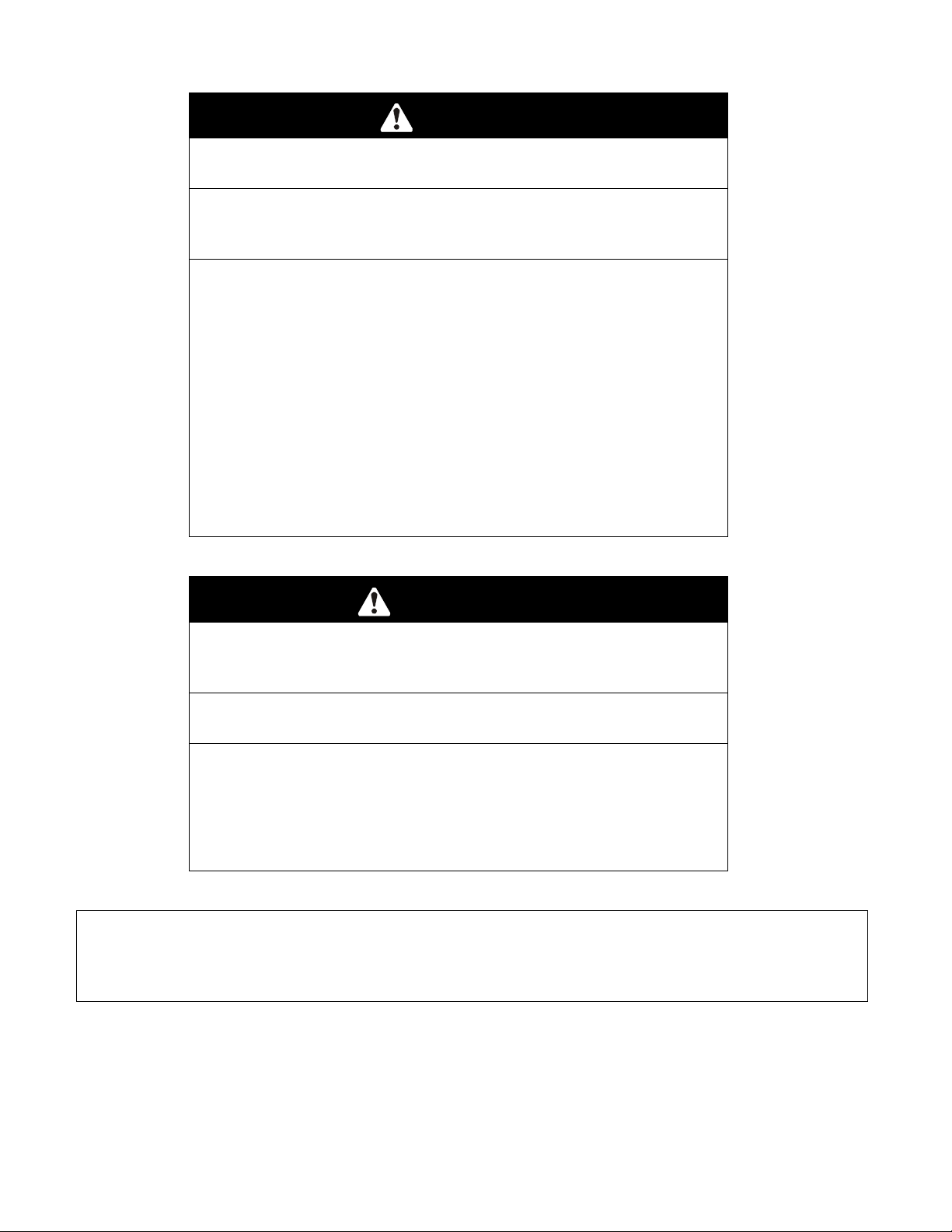
WARNING
POTENTIAL HAZARD
♦ Engine exhaust contains carbon monoxide, which is
an odorless deadly poison.
WHAT CAN HAPPEN
♦ Carbon monoxide can kill you and is also known to the
State of California t o cause birth defects.
HOW TO AVOID THE HAZARD
♦ Do not run engine indoors or in a small confined area
where dangerous carbon monoxide fumes can collect.
DANGER
POTENTIAL HAZARD
♦ In certain conditions gasoline is extremely flammable
and highly explosive.
WHAT CAN HAPPEN
♦ A fire or explosion from gasoline can bur n you, ot hers,
and cause property damage.
HOW TO AVOID THE HAZARD
♦ DO NOT smoke while refueling , and stay away from
an open flame or where gasoline fumes m ay be ignited
by spark.
♦ Refuel only in a well ventilated area, or refuel
outdoors.
♦ Store gasoline in an approved container and keep it
out of the reach of children.
♦ Add fuel before start ing the engine. Never remove the
cap of the fuel tank or add fuel when engine is running
or when the engine is hot.
♦ Never fill the fuel tank so that the gasoline level rises
above a level that is 1/2” below the bottom of the filler
neck to allow for gasoline expansion and prevent fuel
spillage.
♦ If fuel is spilled, DO NOT attempt to start the engine.
Move away from the area of the spill and avoid
creating any source of ignition unt il fuel vapors have
dissipated.
- 2 -
Page 8

DANGER
POTENTIAL HAZARD
♦ In certain conditions gasoline is extremely flammable
and highly explosive.
WHAT CAN HAPPEN
♦ A static charge can ignite g asoline vapors. A fire or
explosion from gasoline can burn you, others, and
cause property damage.
HOW TO AVOID THE HAZARD
♦ Purchase and store gasoline only in an approved
container.
♦ Always place gasoline containers on the ground away
from your vehicle before f illing.
♦ Do not fill gasoline containers inside a vehicle or on a
truck or trailer bed because inter ior car pets or plastic
truck bed liners may insulate the container and slow
the loss of any static charge.
♦ When practical, r emove gas-powered equipment from
the truck or trailer and refuel the equipment with its
wheels on the ground.
♦ If this is not possible, then refuel such equipment on a
truck or trailer from a portable container, rather than
from a gasoline dispenser nozzle.
♦ If a gasoline dispenser nozzle must be used, keep the
nozzle in contact with the rim of the fuel tank or
container opening at all times until fueling is complete.
WARNING
POTENTIAL HAZARD
♦ Gasoline vapor can collect inside enclosed trailers and
may be ignited by electrical sparks or hot
engine/exhaust components.
WHAT CAN HAPPEN
♦ Explosion and fire may occur, resulting in proper t y
damage, personal injury and/or death.
HOW TO AVOID THE HAZARD
♦ Provide adequate ventilation of any enclosed trailer to
prevent build up of gasoline vapors, especially at floor
level.
♦ Never refuel equipment inside an enclosed tr ailer .
♦ Be sure all fuel tanks and gasoline st or age containers
have proper caps installed to prevent spillage and
minimize vapor escaping into the trailer.
♦ Do not place any equipment that is leaking gasoline in
an enclosed trailer.
- 3 -
Page 9

1.4 OPERATION
Although hazard control and accident prevention are parti al l y dependent upon the
design and configuration of the equipment, these factors are also dependent upon
the awareness, concern, prudence and proper training of the personnel i nvol ved in
the operation, transport, maintenance and st orage of t he equi pment . It is essential
that all Operator Safety Mechanisms be connect ed and i n operat ing condition prior
to use for mowing.
POTENTIAL HAZARD
♦ Operating engine parts, especially the m uffler, become
extremely hot.
WHAT CAN HAPPEN
♦ Severe burns can occur on contact.
♦ Debris, such as leaves, grass, brush, etc. can cat ch fire.
HOW TO AVOID THE HAZARD
♦ Allow engine parts, especially the muff ler , to cool before
touching.
♦ Remove accumulated debris from muffler and engine area.
♦ Install and maintain in working order a spar k arrester before
using equipment on forest - covered, grass-covered, brushcovered unimproved land.
WARNING
WARNING
POTENTIAL HAZARD
♦ Hands, feet, hair, clothing, or accessories can become
entangled in rotating part s.
WHAT CAN HAPPEN
♦ Contact with rotating parts can cause traum at ic am putation
or severe lacerations.
HOW TO AVOID THE HAZARD
♦ Operate equipment with all guards in place.
♦ Keep hands, feet, hair, je welry, or clot hing away from
rotating parts.
1.4.1 Give complete, undivided attent ion t o the job at hand.
1.4.2 Mow only in daylight or good artificial light. NEVER carry passengers.
DO NOT operate the mower when children or others are in the area.
1.4.3 When feasible, avoid operating the equipment in wet grass.
1.4.4 Use EXTREME caution when mowing and/or turning on slopes as loss of traction
and/or tip-over could occur. Drive slower on slopes. Progressively great er care
is needed as the slope increases. DO NOT mow slopes greater t han 15
degrees. Watch for ditches, holes, rocks, dips, and rises that change the
operating angle. Keep away from drop-offs and steep banks. Avoid sudden
starts when mowing uphill - mower may tip backwards. Loss of traction may
occur going downhill - weight transfer to the front wheels may cause drive
wheels to slip and cause loss of braking. DO NO T m ow slopes when grass is
wet - slippery conditions affect steering and r educe traction and braking. The
operator is responsible for safe operation on slopes. See inside the back cover
to determine the approximate slope angle of the area to be mowed.
- 4 -
Page 10

1.4.5 Use EXTREME caution when backing up. LOOK BEHIND YOU!
1.4.6 Stop the blades when crossing surfaces other than grass and when transporting
the mower to and from the area to be m owed.
1.4.7 Never operate the mower with damaged guards, shields, or covers. Always have
safety shields, guards, switches, and other devices in place and in proper
working condition.
1.4.8 DO NOT chang e the engine governor settings or overspeed the eng ine. Operating
an engine at excessive speed may increase the hazard of personal injury.
1.4.9 Disengage blade dr ive before starting engine.
1.4.10 Start
the engine carefully with feet well away from the blades.
1.4.11 Keep hands, feet and clothing away from r ot a t ing parts while the mower is being
operated.
1.4.12 Stop the engine and remove ignition k ey:
• Before checking, cleaning or work ing on the mower.
• After striking a foreign object (inspect the m ower for damage and make
repairs before restart ing and operating the mower).
• Before clearing blockages.
• Whenever you leave the mower.
Stop the engine:
• Before refueling.
• Before dumping the gr ass cat c her .
1.4.13 Allow the engine to cool before stopping t he engine.
1.4.14 The fuel system is provided with a shut-off valve. Shut off the fuel:
• When the machine will not be used for a few days.
• During transport to and f r om the job.
• When parked inside a building.
1.4.15 This mower was designed for one operator only. Keep all others away fr om
mower during operation.
1.4.16 Do Not mow without the discharge chute in place.
1.4.17 If jump starting is required:
a) connect the positive (+) power cable from the posit ive post on the booster
battery to the positive terminal post on the st ar t er solenoid switch (this post
has the positive battery cable attached to it).
b) connect the negative or ground cable (-) from the negative post on the
booster battery to the engine block as far away from the battery as possible.
c) disconnect batt er y cables in the r everse order after starting.
1.5 MAINTENANCE AND STORAGE
1.5.1 For engine maint enance, follow the engine manufacturer’s r ecom m endat ions
precisely as stated in the engine manual.
1.5.2 Disconnect the batt er y cable from the negative battery post when the unit will be
allowed to sit for more than 30 days without use.
1.5.3 Allowing batteries to stand for an extended period of time without recharging
them will result in reduced performance and ser vice life. To preserve optimum
battery performance and lif e, recharge batteries in storage when the open
circuit voltage drops to 12.4 volts.
Note: To prevent damage due to freezing, battery should be fully charged
before putting away for winter storag e.
- 5 -
Page 11

1.5.4 Store f uel in a container specifically designed for this pur pose in a cool, dry place.
1.5.5 Keep the mower and fuel container in locked storage to prevent children from
playing or tampering with them.
1.5.6 Gasoline powered equipment or fuel containers should not be stored in a basement
or any enclosed area where open pilot lights or heat appliances are present.
1.5.7 Maximum mowing results and safet y can only be achieved if the m ower is
properly maintained and operated correctly.
1.5.8 Check all bolts frequently to maintain proper t ightness.
1.5.9 Keep all guards, shields and all safety devices in place and in safe working
condition.
1.5.10 Frequently check for worn or deterior ating components that could create a hazard.
1.5.11 All replacement parts must be the same as or equivalent to the parts supplied as
original equipment.
WARNING
POTENTIAL HAZARD
♦ Hydraulic fluid escaping under pressure can penetrat e
skin and cause injury.
WHAT CAN HAPPEN
♦ Fluid accidentally injected into the skin must be
surgically removed within a few hours by a doctor
familiar with this form of injury or gangr ene m ay result .
HOW TO AVOID THE HAZARD
♦ Make sure all hydraulic fluid hoses and lines are in
good condition an all hydraulic connections and fittings
are tight before applying pressure to hydraulic system.
♦ Keep body and hands away from pinhole leaks or
nozzles that eject high pressure hydraulic fluid.
♦ Use cardboard or paper to find hydraulic leaks.
♦ Safely relieve all pressure in the hydraulic system
before performing any work on t he hydraulic system.
For Kawasaki Liquid-Cool ed uni ts:
WARNING
POTENTIAL HAZARD
♦ Engine coolant is hot and pressurized.
♦ Radiator and surrounding parts are hot .
WHAT CAN HAPPEN
♦ Spray or steam from hot, pressurized liquid in the
engine cooling system and touching a hot radiat or
may cause severe burns.
HOW TO AVOID THE HAZARD
♦ Allow the engine to cool completely before removing
the radiator cap or servicing any component of the
cooling system.
- 6 -
Page 12
POTENTIAL HAZARD
♦ Engine coolant is toxic.
WHAT CAN HAPPEN
♦ Swallowing coolant can cause poisoning.
HOW TO AVOID THE HAZARD
♦ Do not swallow
♦ Keep out of reach of children and pets.
For Kohler 26 HP EFI Units:
POTENTIAL HAZARD
♦ Fuel system components are under high pressure.
WHAT CAN HAPPEN
♦ The use of improper components can r esult in system
failure, gasoline leakage and possible explosion.
HOW TO AVOID THE HAZARD
♦ Use only approved fuel lines and fuel filters for high
pressure systems.
CAUTION
WARNING
1.6 SAFETY SIGNS
1.6.1 Keep all safety signs legible. Remove all gr ease, dir t and debris from safet y
signs and instructional labels.
1.6.2 Safety signs must be replaced if they are missing or illegible.
1.6.3 When new components are installed, be sur e that current safety signs are
affixed to the replaced components.
1.6.4 New safety signs may be obtained from your authorized Exmark equipment
dealer or distributor or fr om Exmark Mfg. Co. Inc.
1.6.5 Safety signs may be affixed by peeling of f the backing to expose the adhesive
surface. Apply only to a clean, dry surface. Smooth to remove any air bubbles.
1.6.6 Familiarize yourself with the following safety signs and inst r uction labels. They
are critical to the safe operation of your Exmark commercial mower.
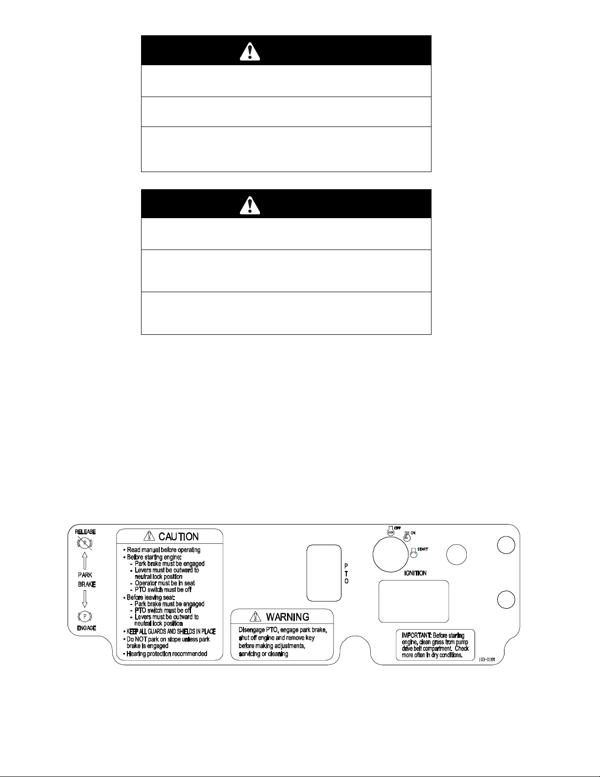
PART NO. 103-0166
LOCATION: LH Side of Console
- 7 -
Page 13
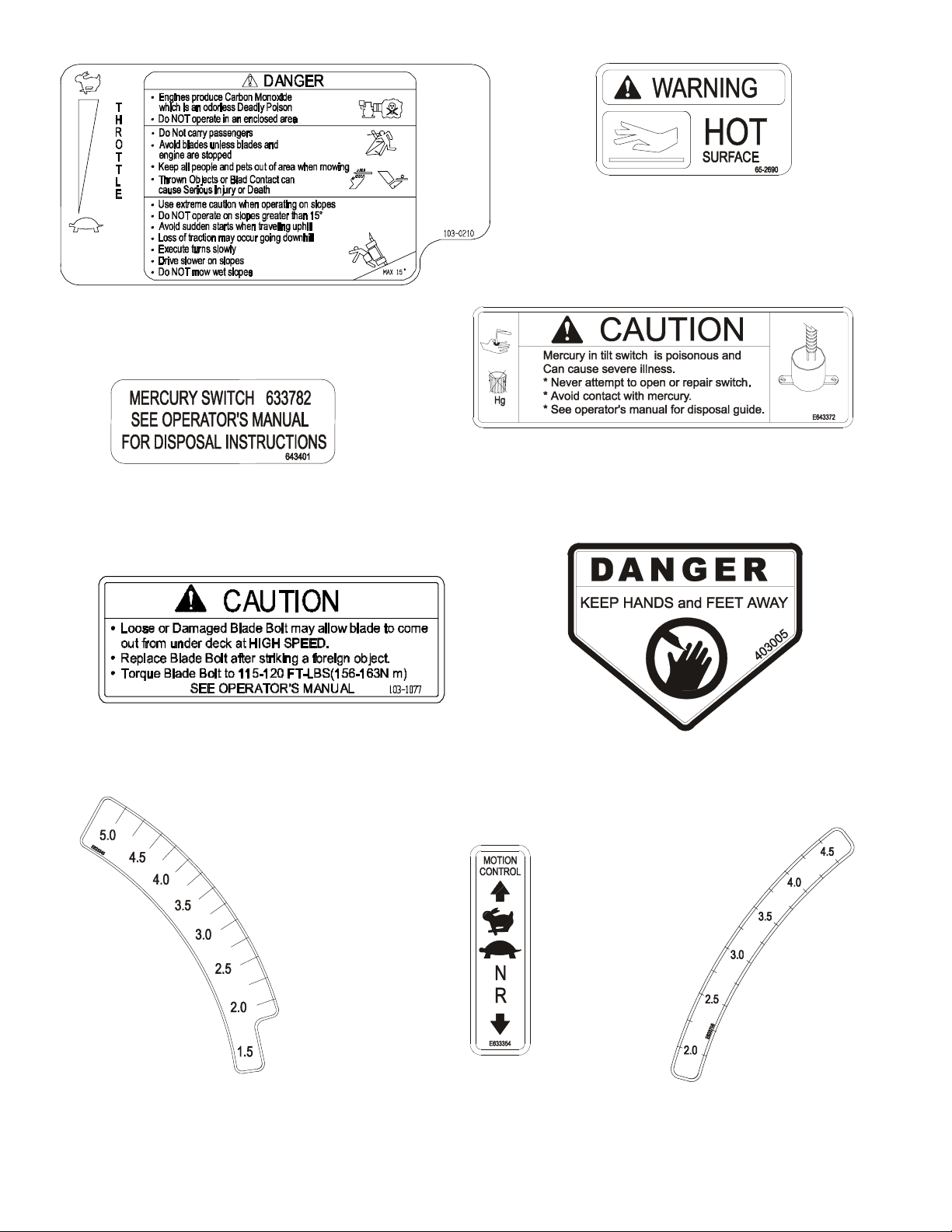
PART NO. 103-0210
LOCATION: RH Side of Console
Serial Nos. 220,000 and Higher
PART NO. 1-643401
LOCATION: On Tilt Switch
PART NO. 65-2690
LOCATION: Top of Radiator Trim Plate
LH & RH Sides
Serial Nos. 220,000 thru 251,999
PART NO. 1-643372
LOCATION: Top LH Side of Console, Under Front of Seat
PART NO. 103-1077
LOCATION: Top LH Side of Mower Deck
next to Stiffener
PART NO. 1-633345
LOCATION: RH Side of Cutting
Height Adjustment Plate
PART NO. 1-403005
LOCATION: Left and Right Corners
of Mower Deck
Serial Nos. 251,999 and Lower
PART NO. 1-633354
LOCATION: Top of Console
PART NO. 1-633706
LOCATION: LH Side of Cutting
Height Adjustment Plate
- 8 -
Page 14
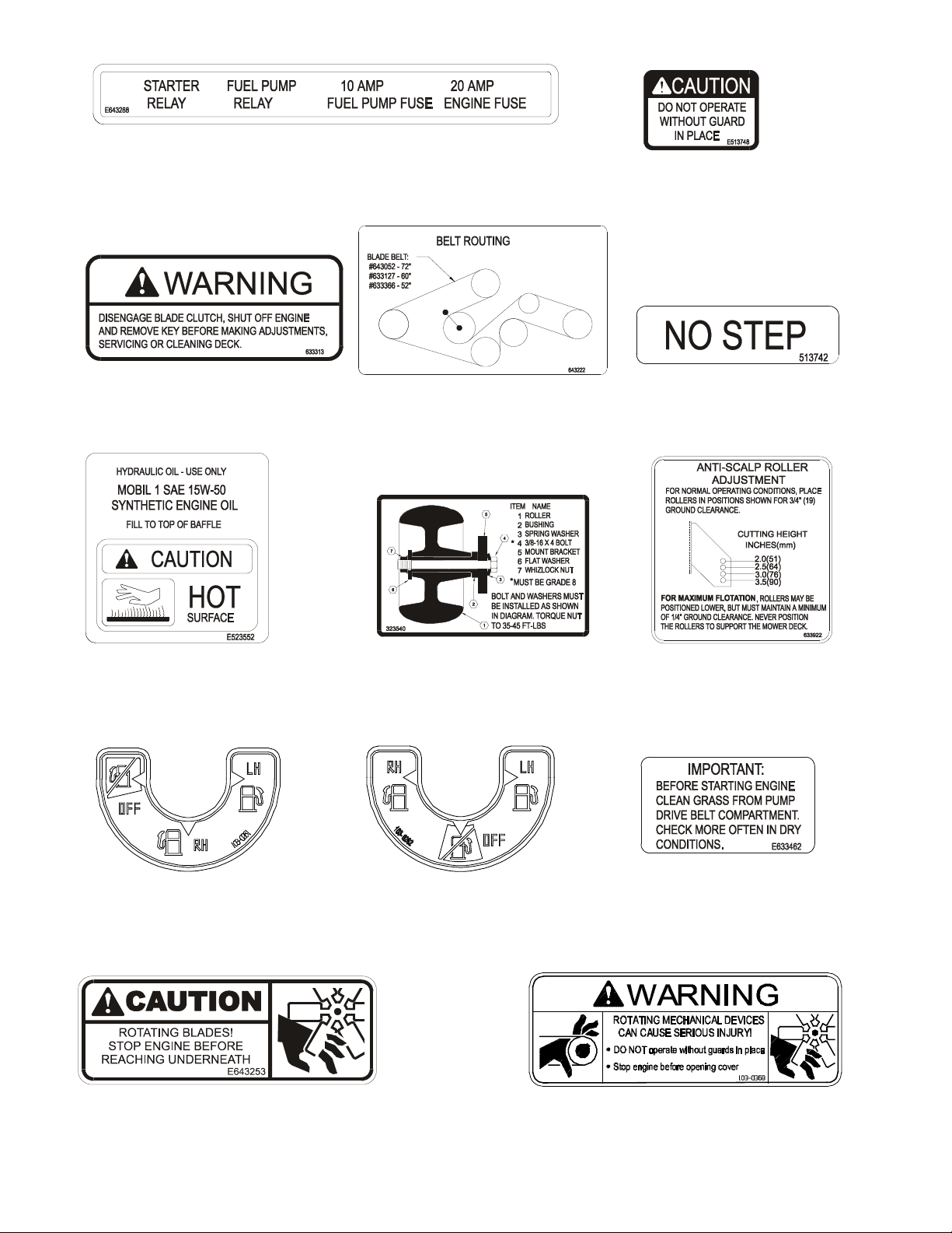
Kohler 26 HP EFI Units Only
PART NO. 1-643288
LOCATION: Panel behind LH Fuel Tank.
PART NO. 1-513748
LOCATIONS: -Rubber Heat Shield
Behind Seat (serial
numbers 259,9999
and lower only)
-Bottom Side of
Floorpan
PART NO. 1-633313
LOCATION: RH Side on Top
Front Mower Deck
PART NO. 1-523552
LOCATION: Top of Hydraulic
Reservoir, Under the Seat
PART NO. 1-643222
LOCATION: Left of Center on Mower
Deck, Under Floor Pan
PART NO. 1-323540
LOCATION: Left Rear Corner Top
of Mower Deck
PART NO. 1-513742
LOCATION: Top of Mower Deck Belt
Shields, Left and Right Sides
PART NO. 1-633922
LOCATION: Front Center on Top
of Mower Deck
Kohler 26 HP EFI Units Only
PART NO. 103-0161
LOCATION: Below Center of
Console
All Units except Kohler 26 HP EFI
PART NO. 103-0162
LOCATION: Below Center
of Console
Kawasaki Liquid-Cooled Units Only
PART NO. 1-643253
LOCATION: LH and RH Sides of Radiator Mount Plate
PART NO. 1-633462
LOCATION: Rubber Heat Shield
Flap behind Seat
PART NO. 103-0368
LOCATION: Rubber Heat Shield Flap behind Seat
- 9 -
Page 15
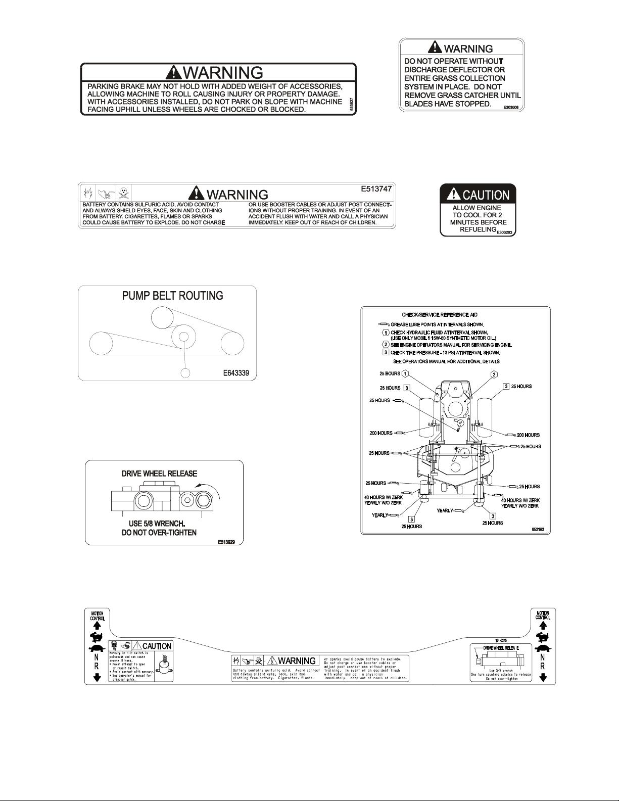
PART NO. 1-633827
p
LOCATION: Top LH Side of Mower Deck Frame
Serial Nos. 251,999 and Lower
PART NO. 1-513747
LOCATION: Top Center of Console, Under Front of Seat
PART NO. 1-643339
LOCATION: Top of Right Engine Baffle
PART NO. 1-303508
LOCATION: RH Side on Top Rear of
Mower Deck
PART NO. 1-303293
LOCATION: On Top of
Fuel Tanks
Serial Nos. 251,999 and Lower
PART NO. 1-513929
LOCATION: Hydraulic Reservoir Mounting Bracket,
Under the Seat
Serial Nos. 252,000 and Higher
PART NO. 103-0245
LOCATION: To
of console
PART NO. 1-633702
LOCATION: Bottom Side of Floor Pan
- 10 -
Page 16

2. SPECIFICATIONS
2.1 MODEL NUMBER:
Serial Nos. 160,000 – 189,999
LZ18KC523; LZ22KC523; LZ25KC523; LZ22KC603; LZ25KC603
Serial Nos. 190,000 – 219,999
LZ18KC523; LZ22KC523; LZ22LKA523; LZ23KC523; LZ25KC523; LZ22KC604;
LZ22LKA604; LZ23KC604; LZ25KC604; LZ26KC604; LZ25KC724; LZ26KC724
Serial Nos. 220,000 – 259,999
LZ22LKA523; LZ23KC523; LZ25KC523; LZ22LKA604; LZ23KC604; LZ25KC604;
LZ26KC604; LZ23LKA604;
Serial Nos. 260,000 and Higher
LZ25KC524; LZ23LKA524; LZ23KA604; LZ23KC604; LZ25KC604; LZ26KC604;
LZ23LKA604; LZ26KC724; LZ27LKA604; LZ27LKA724
2.2 ENGINE:
2.2.1 Engine Specifications: See your Engine Owner’s Manual
2.2.2 RPM: 18, 22, 23, & 25 HP Kohler
Full Speed: 3600 RPM (No Load) Idle:1500 RPM
26 HP EFI Kohler and 23 HP Kawasaki Liquid-cooled models
Full Speed: 3750 RPM (No Load) Idle:1500 RPM
27 HP Kawasaki Liquid-cooled models
Full Speed: 3750 RPM (No Load) Idle: 2200 RPM
2.3 FUEL SYSTEM
2.3.1 Capacity: 9.0 g al. (34 L.) for Serial Nos. 160,000-189,999
11.0 gal. (42 L.) f o r Ser ial Nos. 190,000 & Higher
2.3.2 Type of Fuel: Regular unleaded gasoline, 87 octane or higher
2.3.3 Fuel Filter:
Kohler Air-cooled units: In-line 15 Micron Kohler P/N 2405002.
Kohler 26 HP EFI units: In-line 22 Micron Exmark P/N 99- 9403 (low pressure).
Kawasaki Liquid-cooled units: In-line 40 Micron Kawasaki P/N 49019-1055
Kawasaki Air-cooled units: In-line Kawasaki P/N 49019-7001
2.3.4 Fuel Shut-Off Valve: 1/4 turn increments ( left tank, “OFF”, right tank)
2.4 ELECTRICAL SYSTEM
2.4.1 Charging System: All Kohler & Kawasaki Air - c ooled unit s - Flywheel Alternator
2.4.2 Charging Capacity: All Kohler & Kawasaki Air-cooled units - 15 amps
2.4.3 Battery Type: BCI Group U1
2.4.4 Battery Voltage: 12 Volt
2.4.5 Polarity: Negative Ground
2.4.6 Fuses: Kohler Air-cooled units –Two 20 amp blade type
Kohler 26 HP EFI units – Two 20 amp and one 10 amp blade type
LZ25KC724; LZ26KC724
and 22 HP Kawasaki Liquid-cooled models
In-line 10 Micron Kohler P/N 2405003 (high pressure).
Kawasaki 22 & 23 HP Liquid-cooled units - External Alternator
Kawasaki 27 HP Liquid-cooled units – 3 Phase Flywheel Alternator
Kawasaki 22 & 23 HP Liquid-cooled units – 37 amps
Kawasaki 27 HP Liquid-cooled units – 30 amps
Kawasaki 22, 23, & 27 HP Liquid-cooled units – One 20 amp and t wo 30
amp blade type
- 11 -
Page 17

2.4.7 Safety Interlock System:
For Kohler units Serial Nos. 251,999 and Lower and all 22 & 23 HP Kaw asaki
Liquid-cooled units:
Operator must be in seat with Blades disengaged, brake engaged, and
motion control levers out (neutral lock) to start engine.
For Kohler (Serial Nos. 252,000 & Higher), all Kaw a saki Air - c ooled and all 27 HP
Kawasaki Liquid-cooled units:
Blades must be disengaged, brake engaged, and motion control l evers out
(neutral lock) to start engi ne. (It is not necessary for the operator t o be in the
seat to start the engine.)
For all units:
Operator must be in seat when Blades are engaged, brake i s disengaged, or
motion control levers are moved in or engine will stop.
Engine will stop if either the left, the right, or both levers are moved from neutral
lock position while brake is engaged.
2.4.8 Tilt Switch: (Serial Nos. 220,000 & Higher) Shuts off the engine when the unit is
tilted more than 60° from horizontal.
2.5 COOLING SYSTEM (Kawasaki Liquid-cooled units only)
2.5.1 Fan: 22 & 23 HP units: Thermostatically controlled electric
27 HP units: Electric with continuous operation with engine running
2.5.2 Coolant Liquid:
Kawasaki 22 HP Liquid cooled: 50/50 mix of ethylene glycol and water.
Kawasaki 23 & 27HP Liquid-cooled: 50/50 mix of DexCool© extended life
antifreeze and water.
2.5.3 Coolant Capacity: 4 quarts
2.6 OPERATOR CONTROLS
2.6.1 Steering and Motion Control:
Separate levers, on each side of the console, contr ol speed and dir ect ion of
travel of the respective drive wheels.
Steering is controlled by varying the position of the levers relative to each other.
Moving motion control levers outward
(in slots) locks the drive system in neutral.
NOTE: Newer motion control levers are adjust able t o two heights.
2.6.2 Blade Engagement Switch: Engag es elect ric clutch (to drive belt) which
engages mower blades.
2.6.3 Parking Brake Lever: Sets br akes.
2.6.4 Deck Height Adjustment Lever: Sets cutting height to desired posit ion.
2.6.5 Deck Lift Assist Lever: Kohler 26 HP EFI unit s and all 72” units – Foot pedal that
assists in raising the deck. (This lever is an optional accessor y for all other
units.)
2.7 SEAT
2.7.1 Type: All units except Kohler 26 HP EFI - Standar d seat with high back, foam
padded (internal suspension) and armrests.
Kohler 26 HP EFI units - Deluxe suspension seat with high back, low prof ile
foam-in-place cushion (dampened, adjust able spr ing suspension) and armrests.
(This seat is an optional accessory for all other units)
2.7.2 Mounting: Hinged to tilt up for access to hydraulic pumps, battery and other
components. Held in tilted position with prop rod. Adjustable fore and aft seat t r ack.
- 12 -
Page 18

2.7.3 Armrests: Standard seat: foam padded flip-up armrests.
Serial Nos. 252,000 and Higher: Armrests with height adjustment.
Optional suspension seat: molded adjustable f lip-up
armrests.
2.7.4 Seat Safet y Switch: Incor por ated into the Safety Interlock System. Time delay
seat switch eliminates rough ground cut-outs.
2.8 HYDROSTATIC GROUND DRIVE SYSTEM
2.8.1 Hydrostatic Pumps: T wo Hydro Gear BDP- 10L variable displacement piston pumps.
2.8.2 Wheel Motors: T wo Parker/Ross with 1 1/4” tapered shafts.
2.8.3 Hydraulic Oil Type: Synthetic Mobil 1 15W- 50.
2.8.4 Hydraulic Oil Capacity: 2.1 qt.(2.0 L.)
2.8.5 Hydraulic Filter: Replaceable cartridge type.
P/N 1-513211: 10 microns, 18 psi bypass (Summer use above 32° F)
P/N 1-523541: 40 microns, 18 psi bypass (Winter use below 32° F)
2.8.6 Speeds: 18, 22, 23, & 25 HP Kohler & Kawasaki Air-cooled
and 22 HP
Kawasaki Liquid-cooled models:
Serial Nos. 160,000-189,999 Serial Nos. 190,000 & Higher
0 - 9.0 mph (14.5 km/hr ) forward. 0 - 9.4 mph (15.1 km/hr) forward.
0 - 4.2 mph (6.8 km/hr ) r everse. 0 – 6.0 mph (9.7 km/hr) r everse.
26 HP Kohler EFI and 23 & 27 HP Kawasaki Liquid-cooled models:
0-9.8 mph (15.8 km/hr ) forward.
0-6.3 mph (10.1 km/hr ) r everse.
2.8.7 Drive wheel release valves allow machine to be moved when engine is not running.
2.9 TIRES AND WHEELS
2.9.1 Tires Drive Front Cstr.
Qty:..........................................2....................................2
Ply:..........................................4....................................4
Infl: ......................................13 psi (90 kPa).............13 psi (90 kPa)
Serial Nos. 160,000–189,999
Size:.................................23 x 10.5-12................13 x 5.00-6
Tread:...............................“Turfmate”...................... Smooth
Kohler Air-cooled Units - Serial Nos. 190,000 - 259,999
Size: w/52”Deck ...............23 x 9.5-12..................13 x 5.00-6
Size: w/60”&72”
Tread:...............................“Turf Master”..................Smooth
Kohler and Kawasaki Air-cooled units Serial Nos. 260,000 & Higher and all
Kawasaki Liquid-cooled Units
Size: w/52” Deck...............23 x 9.5-12.....................13 x 6.50-6
Size: w/60” & 72” Deck.....24 x 12.0-12...................13 x 6.50-6
Tread:...............................“Turf Master”..................Smooth
Deck .......24 x 12.0-12................13 x 6.50-6
2.10 CUTTING DECK
2.10.1 Cutting Width: 72 in. (182.9 cm)
60 in. (152.4 cm)
52 in. (132.1 cm)
2.10.2 Discharge: Side
2.10.3 Blade Size: (3 ea.) w/52” Deck 18.0 in. (45.7 cm)
w/60” Deck 20.5 in. (52.1 cm)
w/72” Deck 24.5 in. (62.2 cm)
2.10.4 Blade Spindles: Solid steel spindles with1” I.D. bearings.
- 13 -
Page 19

2.10.5 Deck Drive: Electric clutch mounted on horizontal eng ine shaft. “B” Section belt
(with self-tensioning idler) from electric clutch to transfer shaft mounted on deck .
Blades are driven by one “B” Section belt (w/self-tensioning idler) from transfer
shaft on deck to blade spindles.
2.10.6 Deck: Full floating deck is attached to out- front support frame. Six anti-scalp
rollers provide maximum turf prot ect ion. Dual deck support shafts add to the
stability of the deck. Deck design allows for bagging, m ulching or side discharge.
Deck Depth:
52” Deck (Serial Nos. 259,999 & Lower): 5.0” (12.7 cm)
52” Deck (Serial Nos. 260,000 & Higher : 5.5” (14.0 cm)
60” Deck (Serial Nos. 160,000-189,999): 5.0” (12.7 cm)
60” Deck (Serial Nos. 190,000
72” Deck: 5.5” (14.0 cm)
2.10.7 Cutting Height Adjustment : an extra-long cushioned lever is used to adjust the
cutting height fr om 1 1/ 2” ( 3.8 cm) to 5” (10.2 cm.) in 1/2” (1.3 cm.) increments
for Serial Nos. 160,000-189,999 and 1/4” (.64 cm) increments for Ser ial No.
190,000 & higher. The cutting height adjustment handle has a transport posit ion
and all adjustments can be made while the operator remains seated. Kohler 26
HP EFI units and all 72” units also have a foot operat ed deck lift assist lever to
aid in raising the deck. (T he deck lift assist lever is an optional accessory for all
other units.)
2.10.8 Mulching Kit: Optional.
2.11 Dimensions
2.11.1 Overall Widt h:
& higher): 5.5” (14.0 cm)
without deck deflector up deflector down
Serial Nos. 160,000-259,999 w/52” Deck 49.8 in. (126.5 cm) 53.4 in. (135.6 cm) 63.1 in. (160.3 cm)
Serial Nos. 260,000 & Higher w/52” Deck 49.8 in. (126.5 cm) 53.4 in. (135.6 cm) 64.2 in. (163.1 cm)
Serial Nos. 160,000-189,999 w/60” Deck 53.8 in. (136.7 cm) 61.4 in. (156.0 cm) 71.0 in. (180.3 cm)
Serial Nos. 190,000 & Higher w/60” Deck 53.5 in. (135.9 cm) 61.4 in. (156.0 cm) 72.9 in. (185.2 cm)
Serial Nos. 190,000 & Higher w/72” Deck 57.3 in. (145.5 cm) 73.2 in. (185.9 cm) 84.3 in. (214.1 cm)
2.11.2 Overall Length:
All Air-cooled units - w/52” & 60” decks - 78. 5 in. (199.4 cm)
w/72” deck – 82.6 in. (209.8 cm)
Kawasaki Liquid-cooled units – w/52” & 60” decks – 80.7 in. (205. 0 cm )
w/72” deck – 84.8 in. (215.4 cm)
2.11.3 Overall Height:
Serial Nos. 160,000-189,999: 44 in. (111.8 cm . )
Air-cooled units Serial Nos. 190,000
& higher: 44.5 in. (113.0 cm.)
Kawasaki Liquid-cooled units – 47.7 in (121.2 cm)
2.11.4 Tread W idth: (center to center of t ires, widthwise)
Drive wheels:
Serial Nos. 160,000 & Higher w/52” Deck – 39.7 in. ( 100. 1 cm )
Serial Nos. 160,000
– 189,999 w/60” Deck - 43.7 in. (111.0 cm)
Serial Nos. 190,000 & Higher w/60” Deck – 41.9 in. ( 106. 4 cm )
Serial Nos. 190,000 & Higher w/72” Deck – 45.9 in. ( 116. 6 cm )
Casters:
w/52” Deck – 37.0 in. (93.9 cm)
w/60” Deck – 39.0 in. (99.1 cm)
w/72” Deck – 47.6 in. (120.9 cm)
- 14 -
Page 20
2.11.5 Wheel Base: (center of caster tire t o center of drive tire)
w/52” & 60” Decks - 50.3 in. (127.8 cm)
w/72” Deck – 54.5 in. (138.4 cm)
2.11.6 Curb Weig ht*
Air-cooled units:
Serial Nos. 160,000 & Higher w/52” Deck – 976 lbs. ( 443. 6 kg)
Serial Nos. 160,000
–189,999 w/60” Deck – 1000 lbs. (454.5 kg )
Serial Nos. 190,000 & Higher w/60” Deck – 1033 lbs. (469.5 kg)
Serial Nos. 190,000 & Higher w/72” Deck – 1106 lbs. (501.7 kg)
22 & 23 HP Kawasaki Liquid-cooled units:
w/52” Deck – 1,196 lbs. (542.5 kg)
w/60” Deck – 1,218 lbs. (552.5 kg)
27 HP Kawasaki Liquid-cooled units:
w/60” Deck – 1,298 lbs. (588.9 kg )
w/72” Deck – 1,306 lbs. (592.6 kg )
* Note: Weight will vary slightly, depending on engine option.
2.12 TORQUE REQUIREMENTS
Bolt Location Torque
Cutter Housing Spindle Nut................................ 75-80 ft-lbs.
Blade Mounting Bolt........................................ 115-120 f t-lbs.
Engine Deck/Front Frame Mount........................ 30-35 ft-lbs.
Anti-Scalp Roller Bolts........................................ 40-45 ft-lbs.
Engine Mounting Bolts (Kohler).......................... 30-35 ft-lbs.
Engine Mounting Bolts (Kawasaki) ..................... 25-30 ft-lbs.
Wheel Lug Nuts.................................................. 90-95 f t-lbs.
Wheel Motor Mounting Bolts............................... 72-77 ft-lbs.
Wheel Hub Slotted Nut............................minimum125 ft-lbs.
3. ASSEMBLY INSTRUCTIONS
3.1 UNCRATE MOWER
3.2 SERVICE BATTERY.
WARNING: Battery posts, terminals, and related accessories contain lead compounds, chemicals known
to the State of California to cause cancer and reproductive harm. Wash hands after handling.
For Serial Nos. 252,000 and higher.
The machine is shipped with a filled lead acid battery.
3.2.1 Tilt seat up to gain access to the battery.
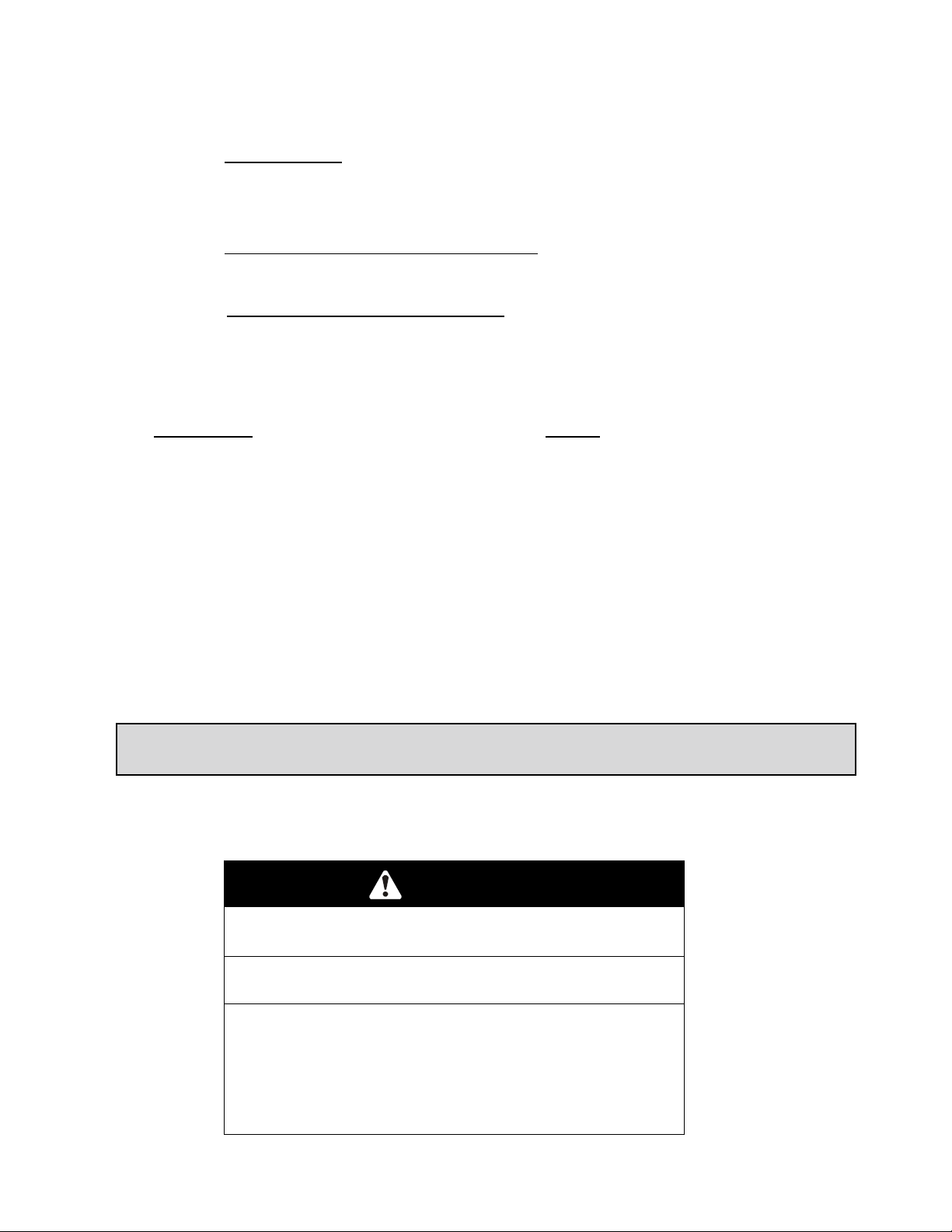
DANGER
POTENTIAL HAZARD
♦ Charging the battery may produce explosive gasses
WHAT CAN HAPPEN
♦ Battery gasses can explode causing serious injury.
HOW TO AVOID THE HAZARD
♦ Keep sparks, flames, or cigarettes away from battery.
♦ Ventilate when charging or using batter y in an
enclosed space.
♦ Make sure venting path of battery is always open once
battery is filled with acid.
- 15 -
Page 21
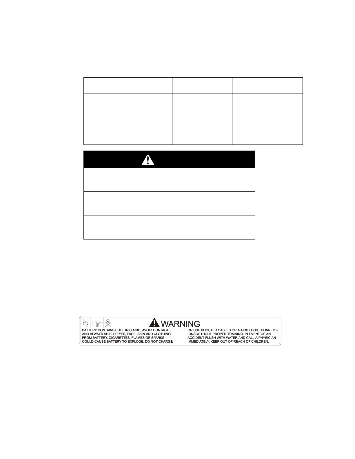
3.2.2 Check the voltag e of the battery with a digital voltmeter. Locat e the voltage reading
of the battery in the table below and charge the bat tery for the recommended time
interval to bring the charge up t o a full charge of 12.6 volts or greater.
IMPORTANT: Make sure the negative battery cables are disconnected and the
battery charger used for charging the battery has an output of 16 volts and 7
amps or less to avoid damaging the batter y (see char t below f or r ecom mended
charger settings).
Voltage
Reading
12.6 or greater 100% 16 volts/7 amps No Charging Required
12.4 – 12.6 75 – 100% 16 volts/7 amps 30 Minutes
12.2 – 12.4 50 – 75% 16 volts/7 amps 1 Hour
12.0 – 12.2 25 – 50% 14.4 volts/4 amps 2 Hours
11.7 – 12.0 0 – 25% 14.4 volts/4 amps 3 Hours
11.7 or less 0% 14.4 volts/2 amps 6 Hours or More
Percent
Charge
Charger Settings
CAUTION
POTENTIAL HAZARD
♦ If the ignition is in the “ ON” position there is potential
for sparks and engag em ent of components.
WHAT CAN HAPPEN
♦ Sparks could cause an explosion or moving parts
could accidentally engage causing personal injury.
HOW TO AVOID THE HAZARD
♦ Be sure ignition switch is in the “OFF” position before
charging the battery.
3.2.3 Connect the negative battery cables.
NOTE: If the positive cable is also disconnected, connect the positive (red)
cable and the red wire to the positive term inal on the battery first, then connect
the negative (black) cable and white/white wire to the negative terminal on the
battery (red wire and white/white wire are only on some units). Slip insulator boot
over the positive terminal.
NOTE: If time does not perm it char ging the battery, or if charging equipment is
not available, connect the negative battery cables and run the vehicle
continuously for 20 to 30 minutes to suf ficiently charge the battery.
Maximum
Charging Interval
For Serial Nos. 251,999 and lower.
The machine is shipped with a dry battery.
3.2.4 Remove battery from machine. Tilt seat up to gain access to t he bat tery.
Disconnect battery cables – negative (black) cable fi rst . Remove battery
hold-down and lift battery out.
- 16 -
Page 22

3.2.5 Place battery on a level surface and r em ove vent caps.
DANGER
POTENTIAL HAZARD
♦ Battery electrolyte contains sulfuric acid, which is
poisonous and can cause severe burns
WHAT CAN HAPPEN
♦ Swallowing electrolyte can be fatal or if it t ouches skin
can cause severe burns.
HOW TO AVOID THE HAZARD
♦ Wear safety glasses to shield eyes, and rubber gloves
to protect skin and clothing when handling elect r olyte.
♦ Do not swallow electrolyte.
♦ Fill the battery where clean water is available for
flushing skin.
DANGER
POTENTIAL HAZARD
♦ Charging the battery may produce explosive gasses
WHAT CAN HAPPEN
♦ Battery gasses can explode causing serious injury.
HOW TO AVOID THE HAZARD
♦ Keep sparks, flames, or cigarettes away from battery.
♦ Ventilate when charging or using batter y in an
enclosed space.
♦ Make sure venting path of battery is always open once
battery is filled with acid.
3.2.6 Fill cells with battery grade sulfuric acid (1.265 specific gr avity) t o halfway
between top of separators and bottom of vent well.
3.2.7 Let battery stand for 1/2 hour after filling. If battery acid level has fallen, refill to
level above plates.
3.2.8 Charge the batt er y at 4 t o 5 am ps for 3-5 hours.
3.2.9 After charging , inst all vent caps and wash of f any acid with water and dry battery.
CAUTION
POTENTIAL HAZARD
♦ If the ignition is in the “ ON” position there is potential
for sparks and engag em ent of components.
WHAT CAN HAPPEN
♦ Sparks could cause an explosion or moving parts
could accidentally engage causing personal injury.
HOW TO AVOID THE HAZARD
♦ Be sure ignition switch is in the “OFF” position.
- 17 -
Page 23

3.2.10 Install battery in machine and secure battery hold-down. DO NOT over-tighten.
All units except 23 HP Kawasaki Liquid-Cooled and 26 HP Kohler EFI:
Connect battery cables - positive (red) cable to t he positive battery terminal
first, then the negative (black) cable and g reen/white wire to the negative battery
terminal. Slip insulator boot over the posit ive ter minal.
23 HP Kawasaki Liquid-Cooled and 26 HP Kohler EFI units:
Connect battery cables - positive (red) cable and red wi r e to the positive
battery terminal first, then the negative (black) cable and white/white wire to the
negative battery terminal. Slip insulat or boot over the positive terminal.
NOTE: If time does not perm it char ging the battery, or if char ging equipment is not
available, follow steps 3.2.4 through 3.2.7 and install as described in 3.2.10. Then
run the vehicle continuously for 20 to 30 minutes to sufficiently charge the battery.
After charging , if battery acid level has fallen, refill battery with clean drinking
water (distilled water is preferred – if available).
3.3 INSTALL DRIVE WHEELS.
3.3.1 Mount drive wheels with the valve stem to the outside of the unit. Secure using
four (4) 1/2-20 x 7/8” UNF wheel bolts (inst alled in hubs) or 1/2-20 wheel nuts
(installed on studs in hubs) for each wheel. Torq ue to 95 ft-lbs (128 NM).
NOTE: Earlier models req uir e t he UNF wheel bolts. Later models have studs
installed in the wheel hub and require wheel nuts.
3.4 CHECK TIRE PRESSURE.
3.4.1 Check tire pressure in caster and drive tires. Proper inflation pressure for all four
(4) tires is 13 psi (90 kPa). Adjust if necessary.
3.5 INSTALL SEAT RETAINING ROD (Standard Seat) or SEAT (Suspension Seat)
3.5.1 For all units with a standard seat: Tilt seat up. Remove 5/16” nyloc nut from bolt
attaching seat retaining r od to seat frame. Remove ignit ion keys attached to bolt.
Remove retaining rod from seat and inser t the “L” shaped end of the rod into t he
hole directly above the left-side hydraulic pump mounting har dware (t he “L” must
be positioned to the right). Posit ion t he seat retaining rod to the outside of t he
mounting tab on the seat f r am e and secur e with 5/16” x 1” bolt and nut. Tighten
until snug, then loosen just enough so t he rod pivots freely.
For all units with a suspension seat: The seat base
frame with adjustable tracks and seat r etaining rod
are already attached to the unit. Remove the
suspension seat from front of crate and discard
the hardware. Position the seat with the front set
of holes on the studs in the adjustable tr acks; be
sure the left and right tracks are aligned (See
Fig.1). Note: newer seats only have one set of
holes. Loosen the vinyl curtain frame at the rear
by pushing down and ahead out of the hole.
Secure the seat with four 5/16 whizlock nuts.
Reattach the vinyl curtain frame. Connect t he
terminal at the end of the wire tied to the seat
frame to the switch in the bottom of the seat.
SEAT INSTALLATION
FIG. 1
SUSPENSION
- 18 -
Page 24

3.6 INSTALL FOOT LIFT ASSIST (Kohler 26 HP EFI and 72” deck units only)
a) Remove the lift assist arm from t he r ear deck lift arm or t he seat base frame (the lift
assist is fastened in this position f or shipping only) and attach to the front deck lift
arm as shown in Fig. 2.
FIG. 2
LEVER ALIGNMENT
3.7 INSTALL CANISTER AIR CLEANER. (Kohler 26 HP EFI units only)
a) Remove air cleaner (with bracket attached) from crat e. Keep air cleaner and
mounting bracket together.
b) Remove the top two valve cover mounting screws from both left and right side
engine valve covers. Keep screws for re-attaching air cleaner .
c) Position the air cleaner assembly over the engine, alig ning air cleaner bracket
holes with top holes in the valve covers. Reinstall valve cover screws through air
cleaner bracket and torque to 70 in. lb. (4.9 N-m).
d) Remove plastic plugs from air intake elbow on engine and air cleaner hose. Adjust
the air cleaner and hose as required and connect intake hose to air cleaner outlet.
Position and tighten the two hose clamps to secure the hose connections.
e) Secure air cleaner by tightening the t ensioning bolt and spring assembly until
ends of clamp are approximately ½” (12.7 mm) apar t.
f) If t he unit has a filter minder, rotate the air intake elbow as needed to create
enough clearance between the filter minder and the oil filler cap to remove and
replace the oil filler cap easily. See Figure 3.
NOTE: The filter minder must clear the lift lug. If necessary, bend the lift lug
towards the back of the machine to gain clearance for the filt er m inder .
FIG. 3
CONTROL ARM SHAFT
- 19 -
Page 25

3.8 INSTALL MOTION CONTROL LEVERS.
3.8.1 Loosen and remove the two (2) 3/8” x 1” bolt s and spr ing disc washers which attach
the motion control levers to the control ar m shafts for shipping and t he
two (2) 3/8” x 1” bolts and spring disc washers which are screwed into the control
arm shafts.
a) Install the left motion control lever ont o the control arm shaft (See Fig .4) on the
left side of the console. Place t he lever ( with the m ounting plate towards the
rear) on the outside of t he cont r ol ar m shaft and secure with the bolts and
washers. Position the lever so the bolts are in the center of t he slots on the
lever mounting plate and tighten unt il snug. Repeat on opposite side of unit.
NOTE: There are two lever height options available on newer units. Place th e
levers in the top two holes to increase height of t he levers, or in the bottom two
holes to decrease the height of t he levers.
If the levers do not align with each other, when in the neutral position, (See
Fig. 5) loosen the hardware and make the appr opr iate adjustment by sliding/tilting
the lever(s) forward or backward until properly aligned and tighten hardware.
MOTION
CONTROL
LEVER
MOUNT PLATE TO
THE REAR & OUTSIDE
OF ARM SHAFT
LEVERS IN
ALIGNMENT
FIG. 4 FIG. 5
CONTROL ARM SHAFT LEVER ALIGNMENT
b) If the ends of the levers hit ag ainst each other, while in the drive position
(levers rotated in as far as possible), make adjustments by moving the levers
outwards to the neutral lock position and carefully bend them outward. Move
them back to the drive position and check for clearance, repeat if necessary.
3.9 POSITION DISCHARGE CHUTE.
3. 9. 1 Loosen two (2) 5/16” nyloc nuts attaching discharge chute. Lower the discharge
chute into position. Retighten nyloc nuts until chut e is snug but can pivot freely.
3.10 SERVICE ENGINE.
Engine is shipped with oil; check oil level and if necessary fill to t he appropriate
level with SAE 10W-30 or 10W-40, AP1 service class SF or SG for operating in
temperatures above 0° F (-18° C). See Eng ine O per ator's Manual.
3.11 SERVICE ENGINE COOLANT (Kawasaki Liquid-cooled Units Only)
Machine is shipped filled with engine coolant.
- 20 -
Page 26

WARNING
POTENTIAL HAZARD
♦ Engine coolant is hot and pressurized.
♦ Radiator and surrounding parts are hot .
WHAT CAN HAPPEN
♦ Spray or steam from hot, pressurized liquid in the
engine cooling system and touching a hot radiat or m ay
cause severe burns.
HOW TO AVOID THE HAZARD
♦ Allow the engine to cool completely before removing
the radiator cap or servicing any component of the
cooling system.
CAUTION
POTENTIAL HAZARD
♦ Engine coolant is toxic.
WHAT CAN HAPPEN
♦ Swallowing coolant can cause poisoning.
HOW TO AVOID THE HAZARD
♦ Do not swallow
♦ Keep out of reach of children and pets.
With machine on l evel surface and with cool engine, r em ove radiat or cap ( under
hood) and add a 50/50 mix of water and engine coolant (as specified in Section
2.5.2) until liquid level is as high as possible without overflowing. Reinstall radiator
cap, making sure that t he cap is com pletely seated by pressing down firmly while
turning until the cap stops. Add 50/50 coolant mix to overflow bottle on the left side
of the engine as requir ed t o bring the level up to the indicator line on the bottle.
NOTE: Kawasaki 23 & 27 HP Liquid-cooled units should only be filled with DexCool© extended life coolant. Dex-Cool© extended life coolant can be identified
by its orange color.
3.12 SERVICE HYDRAULIC OIL
The machine is shipped with hydraulic oil filled to the top the baffle in the
reservoir. Run the machine for appr oximat ely 15 minutes t o allow any extra air
to purge out of the hydraulic system. Check hydraulic reservoir and if necessary
fill the reservoir to the appropriate level with Mobil 1 15W-50 synthetic motor oil.
4. OPERATION INSTRUCTIONS
4.1 CONTROLS
4.1.1 Familiarize yourself with all controls before operating the mower.
4.1.2 Motion Control Levers: Located on each side of the console. The left lever
controls the flow of hydraulic oil from the left hydrostatic pump to the left drive
wheel motor. The right lever controls the flow of hydraulic oil from the r ight
hydrostatic pump to the right drive wheel motor.
IMPORTANT: To begin movement (forward or backward) the operator must
be in the seat, the brake lever must be disengaged (pushed down) before
the motion control levers can be moved in or the engine will kill.
- 21 -
Page 27

When levers are centered in the T-slot the drive system is in the neutral posit ion.
With levers moved out in t he T-slot the drive system is in the neutral lock
position (See Fig. 6).
FIG. 6
MOTION CONTROL POSITIONS
By moving both levers an equal amount forward or back from the neutral position
the machine can be caused to move forward or backward in a straight line.
Movement of the left lever forward will cause the left drive wheel to rotate in a
forward direction. Movement of the right lever f orw ard will cause the right
drive wheel to rotate in a f orward direction. To stop forward travel, pull the
levers back to the neutral position.
To turn left while moving forward, move the left lever back toward neutral to
slow the left drive wheel.
To turn right while moving forward, move the right lever back toward neutral t o
slow the right drive wheel.
To make a zero turn to the left, pull the left lever back beyond neutral while
holding the right lever slight ly ahead of neutral.
To make a zero turn to the right, pull the right lever back beyond neutr al while
holding the left lever slight ly ahead of neutral.
Pulling the levers back from t he neutral position will cause the respective drive
wheels to rotate in a reverse direction (spring tension can be felt when moving
into reverse from neutr al) .
To turn to the left while backing, move the left lever f o r ward toward neutral. To
turn to the right while backing , m ove the right lever forward toward neutral.
CAUTION
POTENTIAL HAZARD
♦ Machine can spin very rapidly by positioning one lever
too much ahead of the other.
WHAT CAN HAPPEN
♦ Operator may lose control of the machine, which may
cause damage to the machine or injury.
HOW TO AVOID THE HAZARD
♦ Use caution when making turns.
♦ Slow the machine down before making sharp turns.
4.1.3 Blade Engagement Switch: Located just left of center on the console (left side of
ignition switch). Switch must be pulled out to the “ROTATE” position to engage
the blades. Switch is pushed in to the “STOP” position to st op t he blades.
- 22 -
Page 28

4.1.4 Choke Control: (All units except Kohler 26 HP EFI) Located at lower center of
console (right side of ignition switch). Choke is used to aid in starting a cold eng ine.
The choke control is pulled out t o be in the “ON” position and pushed in to be in
the “OFF” position. DO NOT run a warm engine with choke in the “ON” position.
4.1.5 Throttle Control: Located on console just right of center.
Throttle is used to control engine speed. Moving throttle lever forward will increase
engine speed and moving throttle lever to the rear will decrease engine speed.
4.1.6 Brake Lever: Located on left side of unit, just to the fr ont of the console. The
brake lever engages a parking brake on the drive wheels.
Pull the lever up and rearward to engage the brake.
Push the lever forward and down to disengage the brake.
When parking on a steep slope, the wheels must be chocked or blocked in
addition to the brake being engaged. The unit must be tied down and brake
engaged when transporting.
4.1.7 Ignition Switch: Located on the lower center of console.
The ignition switch is used to start and stop the engine. The switch has three
positions “OFF”, “ON” and “START”. Insert key into switch and rotate clockwise
to the “ON” position. Rotat e clockwise to the next position to engage the starter
(key must be held against spring pr essur e in t his position).
For Kohler units Serial Nos. 251,999 and Lower and 22 & 23 HP Kaw asaki
Liquid-cooled units:
Operator must be in seat with brake engaged, moti on cont rol levers out
(neutral lock position) and blade engagement sw i t ch “OFF” to start engine.
For Air-cooled units Serial Nos. 252,000 and Higher and 27 HP Kaw asaki Liquidcooled units:
Brake must be engaged, motion control levers out (neutr al l ock position)
and blade engagement switch “OFF” to start engi ne. ( I t is not necessary for
the operator to be in the seat to star t the engine.)
4.1.8 Hour Meter: Located left on center of console. The hour meter is connected to a
pressure switch installed in the engine block and it recor ds t he num ber of hours
that the engine has run. If the ignition switch is left on without engine running,
hour meter will not run.
NOTE: This switch is not a low oil sensor and will not alert the operator if the
engine oil is low.
4.1.9 Fuel Shut-Off Valve: Locat ed dir ect ly below center of console. The fuel shut-off
valve is used to shut off the fuel when the machine will not be used for a few days,
during transport to and from the job site, and when parked inside a building. The
valve has three positions, each position made in 1/4 turn increment s.
NOTE: The positions f or the Kohler 26 HP EFI units are diff e r ent than all other
units. Reference the table below for t he correct locations.
VALVE POSITION
FUEL FLOW Carburetor engines 26 hp, EFI engine
“OFF” DOWN RIGHT
RIGHT TANK RIGHT DOWN
LEFT TANK LEFT LEFT
4.1.10 Drive Wheel Release Valves: Located on the t op left front corner of hydrostatic
pumps. Drive wheel release valves are used to release the hydrostatic drive
system to allow the machine to be pushed without the engine running. Tilt seat
up to gain access to pumps.
- 23 -
Page 29

With a 5/8 wrench, t ur n bot h valves one turn count er - clockwise to release drive system.
Turn clockwise to reset system. DO NOT overtighten. DO NOT tow machine.
4.1.11 Electronic Control Unit Malfunction Indicat or : (Kohler 26 HP EFI units only) The
electronic control unit (ECU) continuously monitor s operation of the EFI system.
If a problem or f ault within the system is detected, the malfunction indicator light
(MIL) is illuminated. The MIL is the red light locat ed on the control console
between the key switch and the throttle controls. Follow the troubleshoot ing
steps outlined in the Kohler engine operator’s m anual if the MIL is illuminated.
4.2 PRE-START
4.2.1 Fill fuel tanks. For best results use only clean, fresh r egular grade unleaded
gasoline with an octane rating of 87 or higher. Regular grade leaded ga soline
may also be used; however, combustion chamber and cylinder head will require
more frequent service. See Engine Owner's Manual.
DO NOT add oil to gasoline.
DO NOT overfill fuel t ank. Never fill the fuel t ank so that the fuel level rises
above a level that is 1/2” below the bottom of the filler neck to allow for fuel
expansion and prevent fuel spillage.
IMPORTANT: The fuel system for Kohler 26 HP EFI units must be purged of all
air prior to start up if t he engine has been allowed to run out of gas or the system
has been disassembled. See Section 5.1.24 for fuel priming (air purg ing)
instructions.
4.2.2 Make sure you understand the controls, their locations, their functions, and t heir
safety requirements.
4.2.3 Refer to Maintenance, Sect ion 5, and perform all the necessary inspection and
maintenance steps.
4.3 MOWING
4.3.1 Open fuel shut -off valve (left or right tank).
4.3.2 Starting Engine:
For Kohler units Serial Nos. 251,999 and Lower and 22 & 23 HP Kaw asaki
Liquid-cooled units:
Operator must be in seat with brake engaged, moti on cont rol levers out
(neutral lock position) and blade engagement sw i t ch “OFF” to start engine.
For Air-cooled units Serial Nos. 252,000 and Higher and 27 HP Kaw asaki Liquidcooled units:
Brake must be engaged, motion control levers out (neutr al l ock position)
and blade engagement switch “OFF” to start engi ne. ( I t is not necessary for
the operator to be in the seat to star t the engine.)
On a cold engine, place the throttle midway between the “SLOW” and “FAST”
positions and pull choke (except Kohler 26 HP EFI units) t o t he “ON” position.
Turn ignition switch to the “star t ” position. Release the switch as soon as the
engine starts.
IMPORTANT: DO NOT crank the engine continuously for more then ten (10)
seconds at a time. If the engine does not start, allow a 60 second cooldown period between starting attempts. Failure to f ol l ow these guidelines
can burn out the starter motor.
After starting a cold engine (except Kohler 26 HP EFI units), gr adually ret u r n
choke to the “OFF” position as the engine warms up.
On a warm engine, place the throttle midway between the “SLOW” and “FAST”
positions and leave the choke in the “OFF” position.
- 24 -
Page 30

4.3.3 Engaging Electric Blade Clutch: The electric blade clut ch push- pull switch
engages the cutting blades. Be sur e t hat all persons are clear of the mower
deck and discharge area before engaging cutt ing blades.
IMPORTANT: Operator must be in seat before the blades can be engaged.
Set throttle to "midway" position. Pull outward on the switch to the “ROTATE”
position. Accelerate to full throttle to begin mowing.
4.3.4 Stopping Electr ic Blade Clutch: Set throttle to the “ idle” position. Push in on the
switch to the “STOP” position stopping t he cut ting blades.
4.3.5 Stopping Eng ine: Br ing unit to a full stop. Disengage the cutting blades, move
motion control levers out to the neutral lock position and set parking brake.
Kawasaki engines: Before stopping t he engine, lower the engine speed to an
idle. Keep on running at idle for about one m inut e; then stop the engine.
Kohler engines: Before stopping the engine, place the throttle cont r ol midway
between the “slow” and “fast” positions. Allow the engine t o run a minimum of 15
seconds; then stop the engine.
Rotate ignition switch to “OFF” posit ion. Rem o ve the key to prevent children or
other unauthorized persons from star t ing engine.
Close fuel shut-off valve when machine will not be used for a few days, when
transporting, and when the unit is park ed inside a building.
4.4 TRANSPORTING
4.4.1 Transporting a Unit: Use a heavy-duty trailer or truck to transport t he m achine. Lock
brake and block wheels. Securely fasten the machine to the trailer or truck with
straps, chains, cable, or ropes. Be sure t hat the trailer or truck has all necessary
lighting and marking as required by law. Secure a trailer with a safety chain.
CAUTION
POTENTIAL HAZARD
♦ This unit does not have proper turn signals, lights,
reflective markings, or a slow moving vehicle emblem.
These items are required t o dr ive on a public str eet or
roadway.
WHAT CAN HAPPEN
♦ Driving on a street or roadway without such equipment
is dangerous and can lead to accidents causing
personal injury.
♦ Driving on a street or roadway without such equipment
may also be a violation of State laws and the operator
may be subject to traffic t ick ets and/or fines.
HOW TO AVOID THE HAZARD
♦ Do not drive a unit on a public street or roadway.
- 25 -
Page 31

WARNING
POTENTIAL HAZARD
♦ Loading a unit on a trailer or truck increases the
possibility of backward tip-over.
WHAT CAN HAPPEN
♦ Backward tip-over of the unit could cause serious
injury or death.
HOW TO AVOID THE HAZARD
♦ Use extreme caution when operating a unit on a ramp.
♦ Use only a single, full width ramp; DO NO T use
individual ramps for each side of the unit.
♦ If individual ramps must be used, use enough ram ps t o
create an unbroken ramp surf ace wider than t he unit .
♦ DO NOT exceed a 15° angle between ramp and
ground or between ramp and trailer or truck.
♦ Avoid sudden acceleration while driving unit up a ramp
to avoid tipping backward.
♦ Avoid sudden deceleration while backing unit down a
ramp to avoid tipping backward.
WARNING
POTENTIAL HAZARD
♦ Gasoline vapor can collect inside enclosed trailers and
may be ignited by electrical sparks or hot
engine/exhaust components.
WHAT CAN HAPPEN
♦ Explosion and fire may occur, resulting in proper t y
damage, personal injury and/or death.
HOW TO AVOID THE HAZARD
♦ Provide adequate ventilation of any enclosed trailer to
prevent build up of gasoline vapors, especially at floor
level.
♦ Never refuel equipment inside an enclosed tr ailer .
♦ Be sure all fuel tanks and gasoline st or age containers
have proper caps installed to prevent spillage and
minimize vapor escaping into the trailer.
♦ Do not place any equipment that is leaking gasoline in
an enclosed trailer.
- 26 -
Page 32

4.4.2 Loading a Unit: Use extreme caution when loading units on trailer s or trucks.
One full width ramp that is wide enough to extend beyond the rear tir es is
recommended instead of individual ramps f or each side of the unit. The lower
rear section of the tractor frame extends back between the rear wheels and
serves as a stop for tipping backward. Having a full width ramp provides a
surface for the frame members to contact if the unit starts to tip back ward. I f it is
not possible to use one full width ramp, use enough individual ramps t o sim ulate
a full width continuous ramp.
Ramp should be long enough so that the angles between the ramp and the
ground and the ramp and the trailer or t r uck do not exceed 15°. A steeper angle
may cause mower deck components to get caught as the unit moves from ramp
to trailer or truck. St eeper angles may also cause the unit to tip backward. If
loading on or near a slope, position the trailer or truck so it is on the down side of
the slope and the ramp extends up the slope. This will minimize the ramp angle.
The trailer or truck should be as level as possible.
DO NOT attempt to tur n t he unit while on the ramp, you may lose control and
drive off the side.
Avoid sudden acceleration when driving up a ramp and sudden deceleration
when backing down a ramp. Both maneuvers can cause the unit to tip backward.
5. MAINTENANCE & ADJUSTMENTS
5.1 PERIODIC MAINTENANCE
5.1.1 Check engine oil level:
Service Interval: Daily
a) Make sure engine is stopped and on a level surface.
b) For Kawasaki Liquid-Cooled units – tilt seat up and t ilt hood forward to gain
access to the engine area.
c) Check with engine cold.
d) Clean area around dipstick. Remove dipstick and wipe oil off. Reinsert the
dipstick and push it all the way down into the tube. Remove the dipstick
and read the oil level.
e) If the oil level is low, wipe off the area around the oil fill cap, remove cap
and fill to the “F” mark on the dipstick. Use oil as specified in Engine
Owner’s Manual. DO NOT overfill.
IMPORTANT: DO NOT operate the engine with the oil level below the “L”
mark on the dipstick, or over the “F” mark.
5.1.2 Check engine coolant level (Kawasaki Liquid-cooled units only)
Service Interval: Daily
a) Make sure engine is stopped and machine is positioned on a level surface.
b) Tilt seat up and tilt hood for ward to gain access to the cooling area.
c) Check with engine cold.
d) View coolant level in overflow bottle on the left side of the engine. Coolant
level should be at the indicator line on the overflow bottle.
e) If the coolant level is low, remove the cap to the overflow bottle and fill to
the indicator line. Use coolant specified in Section 2.5.2.
NOTE: Kawasaki 23 & 27 HP Liquid-cooled units should only be filled with DexCool© extended life coolant. Dex-Cool© extended life coolant can be identified
by its orange color.
- 27 -
Page 33

WARNING
POTENTIAL HAZARD
♦ Engine coolant is hot and pressurized.
♦ Radiator and surrounding parts are hot .
WHAT CAN HAPPEN
♦ Spray or steam from hot, pressurized liquid in the
engine cooling system and touching a hot radiat or
may cause severe burns.
HOW TO AVOID THE HAZARD
♦ Allow the engine to cool completely before removing
the radiator cap or servicing any component of the
cooling system.
CAUTION
POTENTIAL HAZARD
♦ Engine coolant is toxic.
WHAT CAN HAPPEN
♦ Swallowing coolant can cause poisoning.
HOW TO AVOID THE HAZARD
♦ Do not swallow
♦ Keep out of reach of children and pets.
5.1.3 Check battery charg e:
Service Interval: Monthly
Allowing batteries to stand for an extended period of time without
recharging them will result in reduced performance and service life. To
preserve optimum battery perfor m ance and life, recharge batter ies in
storage when the open circuit voltage drops to 12. 4 volts.
Note: To prevent damage due to freezing, battery should be fully
charged before putting away for winter stor age.
a) Check the voltage of the battery with a digital voltmeter. Locate the voltage
reading of the batter y in the t able below and charge the battery for the
recommended time interval to bring t he charge up to a full charge of 12.6
volts or greater.
IMPORTANT: Make sure the negative battery cables are disconnected
and the battery charger used for char ging the battery has an output of 16
volts and 7 amps or less to avoid damaging the batter y (see char t below f or
recommended charger settings).
Voltage
Reading
12.6 or greater 100% 16 volts/7 amps No Charging Required
12.4 – 12.6 75 – 100% 16 volts/7 amps 30 Minutes
12.2 – 12.4 50 – 75% 16 volts/7 amps 1 Hour
12.0 – 12.2 25 – 50% 14.4 volts/4 amps 2 Hours
11.7 – 12.0 0 – 25% 14.4 volts/4 amps 3 Hours
11.7 or less 0% 14.4 volts/2 amps 6 Hours or More
Percent
Charge
Maximum
Charger Settings
Charging Interval
IMPORTANT: For 26 HP Kohler EFI units, unplug the harness from
the ECU before performing any welding on the equipment.
- 28 -
Page 34

5.1.4 Clean engine cooling system:
Service Interval: Daily or more often in dry condi t i ons
CAUTION
POTENTIAL HAZARD
♦ Excessive debris and damaged or missing rubber
baffles can cause the engine and hydraulic system to
overheat.
WHAT CAN HAPPEN
♦ Excessive debris around the engine cooling air intake
and inside of the pump drive belt compartment can
create a fire hazard.
HOW TO AVOID THE HAZARD
♦ Clean all debris from inside of pum p dr ive belt
compartment daily.
a) Stop engine and remove key.
b) Air-cooled units - Clean all debris from rotating engine air intake screen and
from around engine shrouding .
c) Clean all debris fr om inside of pump drive belt compartment.
d) Air-cooled units - Inspect rubber engine baf fles for proper fit . Replace if
necessary.
e) Kawasaki Liquid-cooled units – W ipe debris from screen in engine cover.
Rotate engine cover forward and wipe debris from r adiator core as required.
Inspect seals in engine cover and replace as necessary.
5.1.5 Clean grass build-up under deck.
Service Interval: Daily
a) Stop engine and remove key.
b) Raise deck to the transport (5” cut t ing height) position. Lift the front of unit
and support unit using jack stands or equivalent support.
Information located:
• On console decal 103-0166 behind
ignition switch
• On decal 1-633462 behind seat on
rubber heat shield flap
CAUTION
POTENTIAL HAZARD
♦ Raising the mower deck for service or m aint enance
relying solely on mechanical or hydraulic jacks could
be dangerous.
WHAT CAN HAPPEN
♦ The mechanical or hydraulic jacks may not be enough
support or may misfunction allowing the unit to fall,
which could cause injury.
HOW TO AVOID THE HAZARD
♦ DO NOT rely solely on mechanical or hydraulic jacks
for support. Use adequate jack stands or equivalent
support.
c) Clean out any grass build- up from underside of deck and in dischar ge chute.
- 29 -
Page 35

5.1.6 Check mower blades.
a) St op engine and remove key.
b) Lift deck and secure in raised position as stated in Section 5.1.5.
c) Inspect blades and sharpen or replace as required.
d) Re-install the blades (if they were removed) by placing a block of wood
between the front or rear baf fles and the blade then torquing t he blade
bolts to 115-120 ft. lbs. Be sur e the spring disk washer cone is installed
toward the bolt head (See Figure 7).
POTENTIAL HAZARD
♦ Operating a mower deck with loose or weakened
blade bolts can be dangerous.
WHAT CAN HAPPEN
♦ A loose or weakened blade bolt could allow a blade
rotating at a high speed to come out from under the
deck, causing serious injury or property damage.
HOW TO AVOID THE HAZARD
♦ Replace the blade bolt after striking a foreign object.
Use only the following replacement parts:
52” & 60” decks Serial Nos. 259,999 & lower
Blade bolt – PN 103-1026
Spring disc washer – PN 1-513208
52” & 60” decks Serial Nos. 260,000 & higher
& all 72” units
Blade bolt – PN 103-0862
Spring disc washer – PN 103-0865
♦ DO NOT lubricate the threads of the bolt or spindle
before assembly.
♦ Torque the blade bolt to 115-120 ft. lbs.
Service Interval: Daily
CAUTION
FIG. 7
BLADE BOLT INSTALLATION
- 30 -
Page 36

5.1.7 Check safet y interlock system.
Service Interval: Daily
For Kohler units with Serial Nos. 251,999 and Lower and all 22 & 23 HP
Kawasaki Liquid-cooled units:
a) Check starting circuit. Starter should crank with operator in seat, parking
brake engaged, cutting blades disengaged and m ot ion cont rol levers moved
out in the neutral lock position.
Try to start with operator out of seat, parking brake engaged, blades
disengaged and motion control levers in neutral lock position - starter must
not crank.
For Air-cooled units Serial Nos. 252,000 and Higher and 27 HP Kawasaki units:
b) Check starting circuit. Starter should crank with, parking brake engaged,
cutting blades disengaged and motion control levers m oved out in t he neut ral
lock position. The operator does not need to be in the seat to st ar t the engine.
For All units:
Try to start with operator in seat, parking brake disengaged, blades
disengaged and motion control levers in the neutral lock posit ion - starter
must not crank.
Try to start with operator in seat, parking brake engaged, blades
engaged and motion control levers in the neutral lock position - starter
must not crank.
Try to start with operator in seat, parking brake engaged, blades
disengaged, and the left motion control lever in, starter must not
crank, repeat again with the right lever in, then with both l evers i n -
starter must not crank.
c) Check t he kill circuits. Run engine at one-t hird throttle, disengage parking
brake and raise off of seat ( but do not get off of machine) engine must
stop after approx. 1/2 second has elapsed (seat has t im e delay k ill switch
to prevent cut-outs on rough terr ain) .
Run engine at one-third throttle, engage cutting blades and raise off of seat
(but do not get off of machine) engine must stop after1/2 second has elapsed.
Run engine at one-third throttle, with brake disengaged, move levers in and
raise off seat (but do not get off of machine) engine must stop aft er 1/ 2
second has elapsed.
Again, run engine at one-thir d throttle, brake engaged, and move left
motion control lever in - engine must st op. Repeat again moving the
right lever in, then moving both levers in - engine must stop whether
operator is on seat or not.
NOTE: If machine does not pass any of these tests, do not operate.
Contact your authorized EXMARK SERVICE DEALER.
IMPORTANT: It is essential that operator safety mechanisms be
connected and in proper operating condition prior to use for mowing.
5.1.8 Check for loose hardware.
Service Interval: Daily
a) Stop engine and remove key.
b) Visually inspect machine for any loose hardware or any other possible
problem. Tighten hardware or correct the problem before operating .
- 31 -
Page 37

5.1.9 Service air cleaner.
For Kohler and Kawasaki Air-cooled units w i t h St andard air cleaner:
a) St op engine and remove key.
b) Loosen wing nut and r em ove air cleaner com par tment cover.
c) Remove foam pre-cleaner element ( Kohler unit s only) and wash in warm
water with detergent. Rinse until all traces of detergent are eliminated and
squeeze out excess water (DO NOT wring). Air dry. Saturate with engine
oil and squeeze out excess oil.
d) Check paper element. Gently tap the flat side of the paper element to
dislodge any dirt. DO NOT wash or use pressurized air to clean paper
element. Replace if dirty, bent or dam aged.
e) Reinst all foam pre-cleaner to paper element ( Kohler units only), then
reinstall paper element and cover.
For Kawasaki Liquid-cool ed and Kohl er 26 HP EFI units with canister t ype,
2 stage cleaner: Service Int erval: 50 hrs.
a) St op engine and remove key.
b) Kawasaki Liquid-cooled only: Tilt seat up and tilt hood forward to gain
access to the air cleaner.
c) Loosen retaining clips and remove air cleaner compart m ent cover.
d) Check paper element. Gently tap the paper element to dislodge any dirt .
DO NOT wash or use pressurized air to clean paper element. Replace if
dirty, bent or damaged.
e) Reinstall paper element. Position the cover so that the rubber dust ejector
is pointing downward and secure with retaining clips.
5.1.10 Check Spark Arrester
For Kawasaki Liquid-cooled 22,23,&27 hp; Kohler 26 hp EFI; Kawasaki
Air-cooled 23 hp engines:
Service Interval: 25 hrs.
more often under severe conditions.
More often under severe conditions.
WARNING
POTENTIAL HAZARD
♦ Hot exhaust system components may ignite gasoline vapors
even after the engine is stopped.
♦ Hot particles exhausted during engine operation m ay ig nit e
flammable materials.
WHAT CAN HAPPEN
♦ Fire may result in personal injury or property damag e.
HOW TO AVOID THE HAZARD
♦ Do NOT refuel or run eng ine unless spark arrester is installed.
Service Interval: 50 hours
1. Shut off eng ine, r e m ove k ey, and wait for all moving parts to stop.
2. Wait f or m uffler to cool.
3. If any breaks in the screen or welds are observed, replace ar r est er .
4. If plugging of the screen is observed, remove arrester and shak e loose par ticles
out of the arrestor and clean scr een with a wire brush (soak in solvent if
necessary). Re-install arrester on exhaust outlet.
- 32 -
Page 38

5.1.11 Change engine oil:
Service Interval: 100 hrs.
NOTE: Chang e oil and filter after first five (5) hrs. of operation.
a) Stop engine and remove key.
b) For Kawasaki Liquid-Cooled units – tilt seat up and tilt hood forward to gain
access to the engine area.
c) Drain oil while engine is warm from operation.
d) Remove the oil drain plug. For Kohler air-cooled units, the oil drain plug is
located at the right under-side of the engine. For the 22 & 23 HP Kawasaki
liquid-cooled units, the oil drain plug is located at the front lef t corner of the
engine. Allow oil to drain then replace drain plug. The 27 HP liquid-cooled
and the 23 HP air-cooled Kawasaki units have an oil drain valve on the left
side of engine. Open valve by rotating counter clockwise to drain oil. Allow
oil to drain then tighten valve by rotating clock wise.
e) Replace the oil filter every other oil change. Clean ar ound oil filter and
unscrew filter to remove. Bef ore reinstalling new filter, apply a thin coating of
oil on the surface of the r ubber seal. Turn filter clockwise until rubber seal
contacts the filter adapt er t hen tighten filter an additional 2/3 to 3/4 turn.
f) Clean around oil fill cap and remove cap. Fill to specified capacity and replace
cap. Use oil recommended in engine owner’s manual. DO NO T overfill.
g) Start the engine and check for leaks.
5.1.12 Change engine coolant: (Kawasaki Liquid-Cooled Unit s only)
Service Interval: 2 years/500 hours* – standard coolant
4 years/4000 hours* – Dex-Cool© extended life
* It is recommended to service at whichever int erval happens first.
a) Stop engine and remove key. Machine must be positioned on level surface.
b) Tilt seat up and tilt hood for ward to gain access to the cooling area.
coolant (orange color)
WARNING
POTENTIAL HAZARD
♦ Engine coolant is hot and pressurized.
♦ Radiator and surrounding parts are hot .
WHAT CAN HAPPEN
♦ Spray or steam from hot, pressurized liquid in the
engine cooling system and touching a hot radiat or
may cause severe burns.
HOW TO AVOID THE HAZARD
♦ Allow the engine to cool completely before removing
the radiator cap or servicing any component of the
cooling system.
- 33 -
Page 39

CAUTION
POTENTIAL HAZARD
♦ Engine coolant is toxic.
WHAT CAN HAPPEN
♦ Swallowing coolant can cause poisoning.
HOW TO AVOID THE HAZARD
♦ Do not swallow
♦ Keep out of reach of children and pets.
Drain coolant when engine is cool. Coolant may be drained from the radiator by
loosening the drain cock in the right r ear corner. The engine block may be
drained by removing the rear radiator hose and/or by rem oving t he dr ain plugs
from the engine block .
For 23 HP Kawasaki Liquid-Cool ed uni ts: The plugs may be accessed from
the back of the engine and ar e locat ed in either cylinder wall adjacent to the
main engine block. The plugs may be identified as hex head bolts with a black
finish. See Figure 8.
For 27 HP Kawasaki Liquid-Cool ed uni ts: The plug may be accessed from
the bottom left hand side of the engine. The plug may be identified as a hex
head bolt with a black finish. See Figure 8.
27 HP KAWASAKI
FIG. 8
COOLANT PLUG LOCATION
a) Re-install all drain plugs and hoses and t ig hten drain cock.
b) Fill radiator with a 50/50 mix of water and engine coolant (as specified in
Section 2.5.2), allowing some room (approximat ely 1/2” ) for expansion. Add
50/50 coolant mix to overflow bottle on the left side of the engine as
required to bring the level up to the indicator line on the bottle.
23 HP KAWASAKI
- 34 -
Page 40

WARNING
POTENTIAL HAZARD
♦ Engine compartment contains open belt drives and fans.
♦ Rotating components can cause injury
WHAT CAN HAPPEN
♦ Fingers, hands, loose clothing or j ewelry can get caught
by the rotating fan and drive shaft.
HOW TO AVOID THE HAZARD
♦ Do not operate machine without the covers in place.
♦ Keep fingers, hands, and clothing clear of rotating
components.
♦ Shut off engine and r em ove the ignition key before
performing maint enance.
e) With the cap off the radiator, tilt hood closed and put t he seat down. Start
the engine. Refer to Sect ion 4. 3.2. Return the seat up and hood forward to
the open position.
f) Operate engine until the engine t her m ostat opens and coolant is circulating
through the radiator core. As air is pur ged from the engine block and the
coolant level drops, add additional coolant to the radiator.
g) When the radiator is completely full and no additional coolant can be
added, continue running the engine and install t he r adiator cap. Make sure
that the cap is completely seated by pressing down firmly while turning unt il
the cap stops. Once the cap is installed, the eng ine m ay be stopped.
5.1.13 Check hydraulic oil level:
Service Interval: 40 hr.
a) Stop engine.
b) Tilt seat up.
c) Clean area around hydraulic reservoir cap and remove cap. Oil level should
be to the top of the baf fle inside the tank. If not, add oil. Use only Mobil 1
15W-50 synthetic motor oil.
WARNING
POTENTIAL HAZARD
♦ Hydraulic fluid escaping under pressure can penetrat e
skin and cause injury.
WHAT CAN HAPPEN
♦ Fluid accidentally injected into the skin must be
surgically removed within a few hours by a doctor
familiar with this form of injury or gangr ene m ay result .
HOW TO AVOID THE HAZARD
♦ Make sure all hydraulic fluid hoses and lines are in
good condition an all hydraulic connections and fittings
are tight before applying pressure to hydraulic system.
♦ Keep body and hands away from pinhole leaks or
nozzles that eject high pressure hydraulic fluid.
♦ Use cardboard or paper to find hydraulic leaks.
♦ Safely relieve all pressure in the hydraulic system
before performing any work on the hydraulic system.
- 35 -
Page 41

5.1.14 Check tire pressures:
Service Interval: 40 hrs.
a) Stop engine and remove key.
b) Inflate all four tires t o 13 psi ( 90 kPa).
NOTE: Do not add any type of tire liner or foam fill material to the tires.
Excessive loads created by foam filled tires may cause failures to the hydro drive
system, frame and other components. Foam filling tires will void the warranty.
5.1.15 Check condition of belts:
Service Interval: 40 hrs.
a) Stop engine and remove key.
b) Tilt seat up. Lift the rubber flap on front side of t he engine to check pump
drive belt.
c) Remove left and right belt shields on deck and lift up floor pan to inspect
deck drive belt.
d) Check under machine to inspect the mule drive belt.
e) Check alternator drive belt behind engine (Kawasaki Liq uid-cooled units only)
f) See Sections 5.2.3, through 5.2.6 for belt adjustment.
5.1.16 Lubricate grease fitting s:
Service Interval: Refer to chart.
a) Stop engine and remove key.
b) Lubricate fittings with one to two pumps of NGLI grade #2 multi-purpose gun
grease.
Refer to the following chart for fitting locat ions and lubrication schedule.
LUBRICATION CHART
FITTING
LOCATIONS
1. Front Caster wheel hubs w/zerk
(Serial Nos. 237,574 & lower)
Front Caster wheel hubs w/o zerk
(Serial Nos. 237,575 & higher)
2. Front Caster Pivots
3. Height Adj. Shaft Bearings 1 5 40 hours
4. Deck Drive Belt Idler Arm 1 1 40 hours
5. Brake Brackets 1 2 200 hours
6. Mule Drive Belt Idler Arm 1 1 40 hours
7. Pump Drive Belt Idler Arm 1 1 40 hours
8. Deck Rear Struts 1 2 40 hours
∗∗∗∗ See Section 5.1.16 c) for special lubrication instructions on the front caster pivots and
Section 5.1.17 for special lubrication inst r uct ions on the front casters wheel hubs.
INITIAL
PUMPS
∗2
∗0
∗0
NO. of
PLACES
2
2
2
SERVICE
INTERVAL
∗40 hours
∗yearly
∗yearly
- 36 -
Page 42

No. 6 (Mule Drive Belt Idler Arm)
Located Under Engine Frame
No. 7 (Pump Drive Belt Idler Arm)
Located Under Engine Frame
No. 4,6, & 7 (Idler Pivots) Monthly disassemble
belt and spring and grease under a “No Load”
condition.
c) Lubricate front caster pivots once a year. Remove hex plug and cap. Thread
grease zerk in hole and pump with grease until it oozes out around top
bearing. Remove grease zerk and thr ead plug back in. Place cap back on.
5.1.17 Lubr icat e cast er wheel hubs:
Service Interval: 40 hours for units with grease zerks.
Once Yearly for units without grease zerks.
a) Identif y which type of caster wheel is installed on the unit. If there is a
grease zerk on the caster wheel hub (Serial Nos. 237,574 and lower),
lubricate fittings with one to two pumps of NGLI grade #2 multi-purpose
gun grease. If there is no grease zerk (Serial Nos. 237,575 and higher),
follow the instructions in steps b) through i).
b) Stop engine and remove key.
c) Disassemble the caster wheels, pry out seals, and inspect bearings for
wear or damage and replace if necessary.
d) Pack the bearings with a NGLI grade #2 mult i- pur pose gun grease.
e) Insert (1) bearing, (1) new seal, and (1) bear ing spacer .
NOTE: Seals (Exmark PN 103-0063) must be replaced.
f) Insert Caster Spacer.
g) With open end of wheel up, fill area inside wheel around caster spacer with
NGLI grade #2 multi-purpose gun grease.
h) Insert the second (1) bearing, (1) new seal, and (1) bear ing spacer.
i) Put wheel and tire assembly on the unit and adj ust by tightening the nyloc
nut until wheel will not turn freely. Back nut off 1/6 of a turn so the wheel
will just turn with a slight amount of drag.
IMPORTANT: To prevent seal and bearing damage, check the bearing
adjustment often. Spin t he caster tire. The tire should not spin freely
(more than 1 or 2 revolutions) or have any side play. If the wheel spins
freely adjust per step i).
5.1.18 Lubricate seat switch actuator : ( All units except for Kohler 26 HP EFI)
Service Interval: 160 hrs.
a) Stop engine and remove key.
b) Tilt seat up.
c) Lubricate switch actuator rod with spray type lubricant or light oil.
5.1.19 Lubricate brake handle pivot:
Service Interval: 160 hrs.
a) Stop engine and remove key.
b) Lubricate bronze bushings on brake handle pivot with a spray type lubricant
or light oil.
- 37 -
Page 43

5.1.20 Lubricate brake rod bushings:
Service Interval: 160 hrs.
a) Stop engine and remove key.
b) Tilt seat up.
c) Lubricate bronze bushings on each end of br ake rod shaft with a spray type
lubricant or a light oil (bushings ar e locat ed to the inside of the flange bear ings).
5.1.21 Lubricate motion control bronze bushings:
Service Interval: 160 hrs.
a) Stop engine and remove key.
b) Tilt seat up.
c) Lubricate bronze bushings on f lang e bear ings securing the motion control
arm shafts with a light oil or a spr ay type lubricant .
5.1.22 Remove engine shrouds and clean cooling fins (Kohler Air- cooled units only):
Service Interval: 80 hrs.
a) Stop engine and remove key.
b) Remove cooling shrouds from engine and clean cooling fins. Also clean
dust, dirt and oil from external sur faces of engine, which can cause
improper cooling.
c) Make sure cooling shrouds are reinstalled. Operating the engine without
cooling shrouds will cause engine damage due to overheating.
5.1.23 Check spark plugs:
Service Interval: 160 hrs.
a) Remove spark plugs, check condition and reset gaps, or replace with new
plugs. See Engine Owners Manual.
5.1.24 Change fuel filter :
Service Interval: As Required
a) A fuel filter is installed between the fuel tank s and t he engine. Replace
when necessary.
For Kohler 26 HP EFI Units:
WARNING
POTENTIAL HAZARD
♦ Fuel system components are under high pressure.
WHAT CAN HAPPEN
♦ The use of improper components can r esult in system
failure, gasoline leakage and possible explosion.
HOW TO AVOID THE HAZARD
♦ Use only approved fuel lines and fuel filters for high
pressure systems.
Note: For Kohler 26 HP EFI units use only high pressure clam ps and SAE R7
or R9 hose available from Exmark or Kohler. Clam ps require special pliers
P/N 1-643394 (Oetiker P/N 14100118 or Kohler P/ N 2445505) for installation.
- 38 -
Page 44

Replacement Filters
Kohler 26 HP EFI
Kohler Air-cooled (except 26 HP EFI)
Kawasaki Liquid-cooled
Kawasaki Air-cooled
Note: When replacing the fuel filter for the Kohler 26 HP EFI units, wet the
interior of the new filter with gasoline before installation to prevent the high
pressure pump from tearing the f ilter.
5.1.25 Fuel pressure relief and priming pr ocedur e: (26 HP Kohler EFI units only)
Service Interval: As required
Exmark P/N 99-9403 (low pressure)
Kohler P/N 2405003 (high pressure)
Kohler P/N 2405002
Kawasaki P/N 49019-1055
Kawasaki P/N 49019-7001
WARNING
POTENTIAL HAZARD
♦ Fuel system components remain under high pressure,
even when the engine is stopped.
WHAT CAN HAPPEN
♦ Failure to relieve pressure from the system can cause
gasoline to spray or spill. Spilled fuel or fuel vapors
could be ignited by hot parts.
HOW TO AVOID THE HAZARD
♦ Allow the engine to cool completely.
♦ Safely relieve the pressure from t he fuel system before
attempting to service the fuel system .
A Kohler pressure gauge with an integr al r elief valve (Kohler Part No. 2445504)
is recommended for relieving pressure and pur ging air in the fuel system.
To relieve the system of pressure:
a) Stop engine and remove key.
b) Allow the engine to cool completely.
c) Connect the black tester hose from the Kohler pr essur e gauge to the test
valve in the fuel rail.
d) Route the clear hose into a portable gasoline container and depress t he
button on the tester relief valve.
IMPORTANT: The fuel system for Kohler 26 HP EFI units must be purged of all
air prior to start up if t he engine has been allowed to run out of gas or the system
has been disassembled.
To purge the air out of the fuel system:
a) Connect the black hose to the test valve in the fuel rail and route the clear
tube into a portable gasoline container.
b) Depress and hold the release button and crank the engine in 10- 15 second
intervals, allowing a 60 second cool-down period between intervals, until air
is purged and fuel is visible in the discharge tube.
NOTE: If you do not have the pressure g auge, you can crank the engine in 1015 second intervals, allowing a 60 second cool-down period between cranking
intervals, until the engine starts.
- 39 -
Page 45

5.1.26 Change hydraulic system filter:
Service Interval: After First 250 hrs.
Then yearly thereafter
NOTE: Use only Exmark Part No. 1-513211 for summer use above 32° F or
Part No. 1-523541 for winter use below 32°
F.
a) St op engine and remove key.
b) Raise seat .
c) Carefully clean area around filt er . It is important that no dirt or
contamination enter hydraulic system.
d) Unscr ew f ilter to remove and allow oil to drain from reservoir.
IMPORTANT: Before reinstalling new filter, fill it with Mobil 1 15W-50 and
apply a thin coat of oil on the surface of the rubber seal.
Turn filter clock wise until rubber seal contacts the filter adapter , t hen
tighten the filter an addit ional 2/ 3 to 3/4 turn.
e) Fill reservoir as stated in Section 5.1.13.
f) Raise the rear of machine up and support with jack stands (or equivalent
support) just high enough t o allow drive wheels to turn freely.
g) Start engine and move thrott le cont r ol ahead to full throttle position. Move
the speed control levers to the full speed and run for several minutes. Shut
down machine and recheck oil level.
Do not change hydraulic system oil (except for what can be drained when
changing filter), unless it is felt the oil has been contaminat ed or been
extremely hot.
Changing oil unnecessarily could damage hydraulic system by
introducing contaminates into the system.
5.1.27 Inspect electric clutch gap:
Service Interval: 250 hrs.
Refer to Section 5.2.12 for inspection and adjustment procedures.
5.1.28 Wheel hub - slotted nut torque specification.
Service Interval: 500 hrs
When tig ht ening the slotted nut on the wheel motor tapered shaft:
a) Torque the slotted nut to 125 ft. lbs.
b) Check distance from bottom of slot in nut to inside edg e of hole. Two
threads (0.1”) or less should be showing.
c) If more than two threads (0.1”) are showing r em ove nut and inst all washer
(PN 1-523157) between hub and nut.
d) Torque the slotted nut to 125 ft. lbs.
e) Then tighten nut until the next set of slots line up with the cross hole in shaft.
f) Replace cotter pin.
5.1.29 Fuel Tank – mounting hardware specification.
When installing the nuts on the fuel tank st uds, fully tighten the nyloc nut and
back off 1/2 turn. T his allows f o r nor m al fuel tank expansion and contraction with
changes in temperature and fuel levels.
5.1.30 Thread locking adhesives such as “Loctite 242” or “ Fel-Pro, Pro-Lock Nut Type”
are used on the following fasteners:
a) Pump drive sheave set screws.
b) Square head setscrews on Hydro pump control arms.
- 40 -
Page 46

c) Sheave retaining bolt in the end of engine crankshaft.
d) Setscrews on the Jackshaft sheaves.
NOTE: Newer models with a Jackshaft assembly, which can be identified
by a cast housing, do not have setscrews on the Jackshaft and Sheaves.
Adhesives such as “Loctite RC/609 or RC/680” or “Fel-Pr o Pr o-Lock Retaining I
or Retaining II” are used on the following:
a) Fuel tank studs, where studs are inserted into tank.
5.1.31 An anti-seize compound is used on the following locations:
a) Between Jackshaft and sheaves.
b) Between Jackshaft and bearing on newer models with a cast Jackshaft
housing.
c) Between sheaves and cutter housing spindles.
d) Between the bearings and the cutter housing spindles.
5.1.32 Dielectric grease is used on all blade type electrical connections to prevent
corrosion and loss of contact.
5.2 ADJUSTMENTS
IMPORTANT: Disengage blade clutch, shut off engine and remove key before
servicing, cleaning or making any adjustments to the unit.
5.2.1 Cutting Heig ht Adjustment.
a) Stop machine and move drive levers out to neutral lock position.
b) Disengage blades.
c) Raise the deck lever to the transport position (also the 5” cutting height
position). See Fig 9.
For Kohler 26 HP EFI units and all 72” units the deck can be raised by
pulling the deck lever up and/or by pushing on the deck lift assist lever.
NOTE: When changing cutting height positions, al ways come to a
complete stop and disengage the mower bl ades.
FIG. 9
CUTTING HEIGHT POSITION
d) Insert height adjustment pin into hole corresponding to desir ed cutting
height and install hairpin cotter. See decals on the sides of deck lift plat e.
e) Move lever out of transport (or 5” cut ting height) position and down onto
height
adjustment pin to mow at selected height.
f) To transport, m ove lever back up to transport (or 5” cutting height) position.
Note: The foot operated deck lift assist lever (standard on 72” uni t s
the Kohler 26 HP EFI units and optional on all other models) can be
used to momentarily lift the deck to clear objects. Be sure that blades
are disengaged.
- 41 -
Page 47

g) Adjust anti-scalp rollers for Normal Operating Conditions. Stop engine and
remove key. Place rollers in one of t he posit ions shown in Fig. 10. Rollers
will maintain 3/4 in. (19 mm) clearance to t he ground to minimize gouging
and roller wear or damage. For Maximum Flotat i on, place r ollers one
hole position lower. Rollers should maintain 1/4 in. (6.4 mm) minimum
clearance to ground. Do Not adjust r ollers to support the deck. Be sure
bolt is tightened properly or loss of ant i- scalp r o ller m ay result .
5.2.2 Deck Leveling
a) Posit ion m ower on a flat surface.
b) St op engine and remove key.
c) Check tire pressure of all four (4) tires. If needed, adjust to 13 psi (90 kPa).
d) Set anti-scalp rollers to top holes or remove them completely for this
adjustment.
e) Raise t he deck to the 5” height position (also t ransport position) and take
all force off of the two large deck lift spr ings by loosening the nuts at the
front of each spring . See Fig. 11.
FIG. 10
ANTI-SCALP ROLLER ADJUSTMENT
f) For 52” and 60” units - Lower the deck to the 1-1/2” height position.
For 72” units – Lower the deck to the 1-1/2” height position. Force the left
rear deck support arm downward about 1/4” to get the deck to rest at the 11/2” height position. Place locking pliers between the rear swivel and spring
stop to hold the deck in this position. See Fig. 11.
g) Place a 3/ 4” thick block of wood under each of t he t wo (2) r ear ant i- scalp
roller brackets and place one under one of the f r ont center anti-scalp
roller brackets.
h) Loosen t he four (4) top chain bolts in slots. Check the length of the rod
swivel assemblies. The distance from the outside of the rear swivel to the
outside of the front swivel should be approximately 20- 1/4 inches (Kawasaki
Liquid-cooled units (Serial Nos. 259,999 & Lower) with a 52” deck should
measure approximately 20 inches). Adjust the length by turning nuts on
either side of the fr ont swivels.
NOTE: Adjust so that all four ( 4) swivels are free in their holes. This may
cause the measurement to vary slightly fr om side t o side.
i) Adjust the two (2) rear upper chain att achm ent bolts in the slots to take the
slack out of the chains. (Deck is still supported by wood blocks under the
caster roller brackets). Tighten hardware on the rear chains.
j) Adjust the two
(2) front upper chain attachment bolts in the slots to take the
slack out of the chains. (Deck is still supported by one wood block under
one of the front r oller br ackets) If the bolt s ar e all the way to the end of the
slots, shorten or lengthen the r od/ swivel assemblies as requir ed, adjust
each side the same amount.
- 42 -
Page 48

k) Recheck that the 3/4” blocks fit just snugly under the brackets and that the
tension on all the chains are approximately equal. Make sure all chain
attachment bolts are tight. Reposition anti-scalp rollers and tighten securely.
SWIVEL ADJUSTMENT
SPRING COMPRESSION ADJUSTMENT
l) Raise deck lift lever to the 5” cutting height position See Fig 9. Adjust spring
compression until proper distance is obtained between the two large washers
(See Fig 11). Adjustment is m ade by turning the nut at the front of each
spring (clockwise will shorten the spring, counter-clockwise will lengthen the
spring). Lock in position with jam nuts.
NOTE: When above adjustments have been made, the front of the
deck will be slightly lower than the rear of the deck.
5.2.3 Pump Drive Belt Tension.
Self-tensioning - No adjustment necessary.
5.2.4 Mule Drive Belt Tension Adjustment.
Self-tensioning idler, adjust as follows:
a) Stop engine and remove key.
b) Check to make sure the center of the bolt head in the center of t he spr ing
loaded pulley, on left side engine deck support , is posit ioned between the
centers of the two alignment holes in t he left support plate (See Fig 12). It is
necessary to adjust the belt tension when the center of the bolt head is at or
below the center of the bottom alig nm ent hole.
c) When adj ustment is necessary, loosen the idler pulley on the right-hand
side so it can move up and down in the slot.
Place a wrench on the 3/8” nut in the center of t he spr ing loaded pulley and
apply upward pressure to relieve tension on the spring (a 1/2” drive break er
bar and 9/16 socket works best).
Reposition the adjusting pulley to the bottom of the slot.
NOTE: When installing a new belt, it is necessary to reposition the r ight
adjusting pulley upward in the slot in order to position the cent er of the
spring loaded pulley between the alignment holes.
FIG. 11
FIG. 12
MULE DRIVE BELT ADJUSTMENT
- 43 -
Page 49

5.2.5 Deck Belt T ension.
a) The deck belt is tensioned by a self-tensioning idler , no adjustment is
necessary.
5.2.6 Alternator belt tension.
(Kawasaki Liquid-cooled units only)
a) Stop engine and remove key.
b) To tighten alternator belt, loosen both upper and lower alternator mounting
bolts. Rotate alternator out , away from engine and re-tighten har dware to
secure in place.
c) When properly tensioned, t he alt er nator belt will deflect 1/8” while applying
5-7 pounds of force to the belt midway between the sheaves.
5.2.7 Adjust Seat Switch (All unit s except Kohler 26 HP EFI )
a) If necessary, adjust the seat actuator r od length to where the machine will
shut off when the operator raises off the seat (with brake disengaged or
blade switch engaged) but will continue to run with operator in seat ( a
slight shift in weight should not shut machine off). Nor m al adjustment is
when length of spring is 2.09” (with seat up) .
NOTE: To prevent rough ground cut-outs the unit is equipped wi t h a t ime
delayed seat switch. When the operator raises off t he seat with either the
brake disengaged or the cutting blades engaged, the engine shoul d st op
after 1/2 second has elapsed.
b) To adjust seat switch, loosen locknut on bottom of the actuator rod (5/16 x 7”
bolt) and adjust the nuts to move the actuat or plate up or down on the rod.
5.2.8 Belt Guide Adjust m ent .
a) Stop engine and remove key.
b) Remove the belt shield on the right side of mower deck.
c) For 52” & 62” unit s only - not e belt guide bolted to deck near the shield
support stud and right-hand pulley. Guide should be 1/8” away from the
belt, with bolt-end of guide at end of slot (See Fig 13).
d) If adjustment is necessary, loosen the bolt securing t he belt guide and
make proper adjustment. Tighten hardware.
FIG. 13
BELT GUIDE POSITIONING
e) There is a stationary belt guide at the rear cent er of the deck. Adjust to
where shank of bolt is 1/4” away from the edge of the sheave. Note: Bolt
head is above belt.
5.2.9 Brake Link Adjustment.
Check to make sure brak e is adjusted properly.
a) Disengage br ake lever (lever down).
b) Measure the length of the spring. Measurement should be 2.75” between
washers (see Fig 14).
- 44 -
Page 50

c) If adjust m ent is necessary, tighten the nut directly below the yoke and
loosen the bottom nut (bottom one of the two tightened together) below the
spring. Turn the nut direct ly below the washer (top nut of the two tightened
together) until the corr ect measurement is obtained. Tighten t he two nuts
together and repeat on opposite side of unit. Turn clockwise to shorten
spring length and turn counter- clockwise to lengthen the spring.
FIG. 14
BRAKE ADJUSTMENT
5.2.10 Brake Adjustment.
a) Check f or br ake link 2.75” measurement as described in section 5.2.9.
b) Engage br ake lever (lever up).
c) Measure the distance between the trunion roller and the r od collar.
Measurement should be 3/16” to 1/4” (See Fig 14).
d) If adjustment is necessary, loosen the nut directly below the yoke. T ur n the
bottom nut (below washer) until the correct measur em ent is obtained (See
Fig 14) turn nut clockwise to lengthen t he gap (screws rod into yoke) and
turn counter-clockwise to shorten the gap ( scr ews rod out of yoke). Tighten
nut against yoke and check opposite side of unit, repeat if necessary.
5.2.11 Adjust Throttle Lever Tension.
a) Stop engine and remove key.
b) Tension in throttle lever can be adjusted by adjusting the tig htness of the
lever pivot bolt, which is located under the console (See Figure 15).
THROTTLE TE NSION
5.2.12 Electric Clutch Adjustment:
For Serial Nos. 260,000 and Higher:
Units have Warner clut ches and no adj ustment is necessary.
For Serial Nos. 259,999 and Lower:
Determine the brand of clutch inst alled on your unit. Ogura clutches can be identified
by 3 bolts with springs. See Fig. 16. Warner clutches do not have these bolts.
No adjustment necessary for Warner clutches.
FIG. 15
- 45 -
Page 51

For Ogura clutches proceed with the following steps:
a) Stop engine and remove key.
b) Engage parking brake.
c) Place .012-. 024 inch feeler gages through each of the three clutch gap
holes. If gap exceeds this range, t ighten the three adjusting nuts unt il t he
proper gap is obtained (See Fig.16). The three clutch gap holes are
located at the “nut side” of t he adjusting bolts. The adjusting bolt s can be
identified by the springs surrounding each bolt.
FIG. 16
CLUTCH GAP ADJUSTMENT
5.2.13 Reverse Indicator Adjustment:
a) Stop engine and remove ignition key.
b) Tilt seat forward.
c) Begin with either the left or right motion control lever. Move lever to the
neutral position and pull lever back until the clevis pin (on arm below pivot
shaft) contacts the end of the slot (just beginning t o put pr essure on
spring), See Fig 17.
d) Check where lever is relative to notch in console (should be centered
allowing lever to pivot outward to the neutral lock position) .
e) If adjustment is needed, loosen the nut against the yoke and while applying
slight rearward pressure on the motion control lever, turn the head of the
adjustment bolt in the appropriat e dir ection until lever is centered (keeping
rearward pressure on the lever will keep the pin at the end of the slot and
allow the adjustment bolt to move the lever to the appr opr iate position).
Tighten lock nut.
f) Repeat on opposite side of unit.
5.2.14 Motion control linkage adjustment.
WARNING
POTENTIAL HAZARD
♦ Engine must be running and drive wheels must be
turning so motion control adjust m ent can be per formed.
WHAT CAN HAPPEN
♦ Contact with moving parts or hot surfaces may cause
personal injury.
HOW TO AVOID THE HAZARD
♦ Keep fingers, hands, and clothing clear of rotating
components and hot surfaces.
- 46 -
Page 52

CAUTION
POTENTIAL HAZARD
♦ Raising the mower deck for service or m aint enance
relying solely on mechanical or hydraulic jacks could be
dangerous.
WHAT CAN HAPPEN
♦ The mechanical or hydraulic jacks may not be enough
support or may misfunction allowing the unit to fall,
which could cause injury.
HOW TO AVOID THE HAZARD
♦ DO NOT rely solely on mechanical or hydraulic jacks for
support. Use adequate jack st ands or equivalent
support.
a) This adjustment must be made with the drive wheels turning. Fir s t raise the
frame and block up so that dr ive wheels can rotate freely.
b) Remove the electrical connection from the seat safety switch, located directly
to the left of t he seat switch assembly beside the hydraulic oil reservoir.
Temporarily install a jumper wire across the term inals in t he connector of
the wiring harness.
c) Run the unit at least 5 m inut es with the dr ive levers at full forward speed to
bring hydraulic system oil up to operating tem per ature.
d) Tilt seat forward.
e) Loosen locknuts from the ball joints on the two rods, which connect the
motion control assemblies to the pump contr ol ar ms (See Fig 17).
NOTE: The nuts to the front t he uni t on each rod have lef t - hand t hreads.
FIG. 17
MOTION CONTROL ADJUSTMENT
f) Start engine. Brake must be engaged and motion control levers out to
start engine. Operator does not have to be in the seat because of the
jumper wire being used. Run engine at full throttle and release br ake.
g) The reverse indicator spring must be correct before the following
adjustments can be made. See Section 5.2.13.
h) Begin on either the left or rig ht side of unit and bring the motion control
lever in to the neutral position. Adjust pum p control rod length by rotating
the double nuts on the rod in the appropriate direction until the wheels
slightly creep in reverse. (See Fig. 17) Move the motion control lever to the
reverse position and while applying slight pressure to the lever allow the
reverse indicator spring to bring t he levers back to neutral. The wheel must
stop turning or slightly creep in re verse.
NOTE: The motion control lever needs to be in neutral while making
any necessary adjustments.
- 47 -
Page 53

The left rod assembly controls the left wheel and the right rod assembly
controls the right wheel.
i) Repeat on opposite side of unit. Tighten
locknuts against ball joints.
j) Shut off unit. Remove jumper wire from
wire harness connector and plug
connector into seat switch.
5.2.15 Caster pivot bearings pre-load adjustm ent .
a) Remove dust cap from caster and tight en
nyloc nut until washers are flat and back
off 1/4 of a turn to properly set the preload on the bearings. If necessar y make
sure the spring washers are reinstalled
as shown in Figure 18.
5.2.16 Seat armrest adjustment.
a) Serial numbers 252,000 and above only (all models except EFI): Lift
armrest on seat. Locate square tab marked with the numbers 1 through 4.
Rotate square tab 1/4 turn to raise or lower the armrest in approximately 1/4”
increments. See Fig. 19.
FIG. 18
CASTER ADJUSTMENT
6. WASTE DISPOSAL
6.1 MOTOR OIL DISPOSAL
Engine oil and hydraulic oil are both pollutants to the environment. Dispose of used oil at
a certified recycling center or accor ding to your state and local regulations.
6.2 ENGINE COOLANT DISPOSAL
POTENTIAL HAZARD
♦ Engine coolant is toxic.
WHAT CAN HAPPEN
♦ Swallowing coolant can cause poisoning.
HOW TO AVOID THE HAZARD
♦ Do not swallow
♦ Keep out of reach of children and pets.
Both Dex-Cool© and the standard engine coolant are 50/50 mixtures of ethylene glycol
(anti-freeze) and water. Ethylene glycol is a pollutant . Dispose of used engine coolant
according to your state and local regulations.
FIG. 19
ARMREST ADJ USTMENT
CAUTION
- 48 -
Page 54

6.3 MERCURY SWITCH DISPOSAL
CAUTION
POTENTIAL HAZARD
♦ The mercury contained in the tilt switch is poisonous.
WHAT CAN HAPPEN
♦ Exposure to mercury can cause severe illness.
HOW TO AVOID THE HAZARD
♦ Never attempt to open or repair the tilt switch
♦ Avoid contact with the mercury.
The tilt switch (PN 1-633782) on this unit contains m er c ur y, a hazardous ma t er ial. Mercury
that is outside a sealed container vaporizes at room temperat ur e. The vapors are harmful.
Mercury can be absorbed through the skin. Do not att empt to open or repair this switch.
A very small amount of mercury is contained in a hermet ically sealed body. The st eel
switch is then potted in a hard epoxy in a plastic case. It is unlikely that the me r cury will
ever escape from the enclosure. These high performance and reliable inexpensive
switches are recyclable. Mercury is an important and beneficial compound but requires
special care in handling and disposal. When used and managed properly, mercury is not
a threat to people or the environment. This information is presented to users so that they
are aware that these switches contain mercury and will apply sound disposal practices
when these devices reach their normal end of life or ar e dam aged.
Several states have passed laws concerning the disposal of devices containing mercury.
In all the remaining states it is advisable to follow similar procedures. The laws state that
these sealed devices contain mercury and should not be placed in the garbage unt il the
mercury is removed and reused, recycled or otherwise managed to insure that it does not
become part of solid waste or waters. Management and disposal practices m ust be within
relevant federal, state or local laws.
Return the switch to your Exmark dealer if it is faulty and is being replaced or if the unit
containing the switch is no longer operating and is being scrapped. If the switch is
damaged or broken open use extreme caution in handling. Call your local waste
management authority or Exmark Cust omer Service for instructions.
6.4 BATTERY DISPOSAL
DANGER
POTENTIAL HAZARD
♦ Battery electrolyte contains sulfuric acid, which is
poisonous and can cause severe burns
WHAT CAN HAPPEN
♦ Swallowing electrolyte can be fatal or if it t ouches skin
can cause severe burns.
HOW TO AVOID THE HAZARD
♦ Wear safety glasses to shield eyes, and rubber gloves
to protect skin and clothing when handling elect r olyte.
♦ Do not swallow electrolyte.
- 49 -
Page 55

Federal law states that batteries should not be placed in the garbage. Management and
disposal practices must be within relevant federal, state or local laws.
If a battery is being replaced or if the unit containing the batt ery is no longer operating and
is being scrapped, take the battery to a local certified recycling center. I f no local recycling
is available return the battery to any certif ied battery reseller.
7. TROUBLE SHOOTING
7.1 MOWER PULLS LEFT OR RIGHT (W/LEVERS FULLY FORWARD).
a) It is common for a machine to pull slightly left or right with levers fully
forward. Move levers forward and compensate as necessary.
b) Check air pressure in tires; 13 psi/drive, 13 psi/pneumatic castors.
c) Check reverse indicator and motion control linkage adjustment. See
section 5.2.13 and 5.2.14.
7.2 MOWER CUTS UNEVENLY.
a) Check air pressure in tires; 13 psi/drive, 13 psi/pneumatic casters. A more
uniform cutting heig ht may be obtained with higher tire pressure on rough
terrain.
A lower tire pressure provides more flotation. Higher pressures in front
casters may cause them to shimmy on hard surfaces.
b) Check deck support chains.
c) Check deck leveling (See Adjustments Section 5.2.2. )
Note: The front of the mower deck will be approximately 1/4” lower than the
back of the mower deck. T his is t he “rake” of the deck.
d) Check blades tip to tip for straig ht ness (they should be within 3/16" or one
blade width from being in line.)
7.3 ENGINE WILL NOT START.
a) Make sure the battery has a full charge. See section 5.1.3 for charging
instructions.
b) For all units except Kohler 26 HP EFI: Be sure the throttle control is
midway between the “SLOW” and “FAST ” positions, and the choke is in the
“ON” position for a cold eng ine or the “OFF” position for a warm eng ine.
c) Make sure there is fuel in the fuel tank and t hat the fuel valve is open.
d) Operator must be in the seat. Be sure the seat switch is proper ly adjust ed.
See Section 5.2.7.
e) Make sure the parking brake is set and mot ion cont r ol levers ar e m oved
out (neutral lock position).
f) Check that the blades are disengaged.
g) Check that the spark plug wires are properly connected.
h) Check for loose or faulty wiring connections.
i) Check for corrosion at all wiring connections. Even minor corrosion may
cause a faulty connection. Clean connector terminals t hor oughly with
electrical contact cleaner, apply dielectric grease and r econnect.
NOTE: When disconnecting electrical connectors DO NOT pull on the
wires to separate the connectors.
NOTE: After carefully checking the above steps, attempt to start the
engine. If it does not start, cont act your authorized Exmark service dealer.
- 50 -
Page 56

IMPORTANT: It is essential that all operator safety mechanisms be
connected and in proper operating condition prior to mower use.
When a problem occur s , do not overlook the simple causes. For example,
starting problems could be caused by an empty fuel tank.
The following table lists some of t he common causes of trouble. Do not att em pt
to service or replace major items or any item s t hat call for special timing of
adjustments procedures (such as valves, governor, etc. ) . Have this work done
by your Engine Service Dealer.
ENGINE TROUBLESHOOTING TABLE
PROBLEM
Will not start
Hard starting
Stops suddenly
Lacks power
Operates erratically
Knocks or pings
Skips or misfires
Backfires
Overheats*
High fuel
consumption
IMPROPER
FUEL
FUEL
XXXXXX X
XX X X X X X
XXX XXX
XXXX X XX
XXXX X X
XX
XXXX
DIRT IN
FUEL LINE
DIRTY AIR
FILTER
XXX X
XX X X
NO
* On Kawasaki Liquid Cooled units check for dirty radiator core.
FAULTY
SPARK
PLUG
XX X
ENGINE
OVERLOADED
BLOCKED
FUEL
FILTER
INCORRECT
OIL
LEVEL
DIRTY
AIR
SCREEN
X
X
X
X
X
X
X
X
INSUFFICIENT
BATTERY
CHARGE
7.4 ENGINE ERROR CODES – KOHLER 26 HP EFI UNITS ONLY
7.4.1 Electronic Control Unit Malfunction Indicator
The electronic control unit (ECU) cont inuously monit or s oper ation of the EFI
system. If a problem or fault within the system is detected, the malfunct ion
indicator light (MIL) is illuminated. The MIL is the red light located on the control
console between the key switch and the throttle controls. Follow the
troubleshooting steps outlined in the Kohler engine operator’s manual if the MIL is
illuminated.
- 51 -
Page 57

8. ELECTRICAL DIAGRAM – KOHLER 18, 22, 23, & 25 HP AIR-COOLED UNITS
Serial Nos. 251,999 and Lower
- 52 -
Page 58

ELECTRICAL DIAGRAM – KOHLER 23 & 25 HP AIR-COOLED UNITS
Serial Nos. 252,000 and Higher
- 53 -
Page 59

ELECTRICAL DIAGRAM – 22 & 23 HP KAWASAKI LIQUID-COOLED UNITS
- 54 -
Page 60

ELECTRICAL DIAGRAM – KOHLER 26 HP EFI UNITS
Serial Nos. 251,999 and Lower
- 55 -
Page 61

ELECTRICAL DIAGRAM – KOHLER 26 HP EFI UNITS
Serial Nos. 252,000 and Higher
- 56 -
Page 62

ELECTRICAL DIAGRAM – 23 HP KAWASAKI AIR COOLED
- 57 -
Page 63

ELECTRICAL DIAGRAM – 27 HP KAWASAKI LIQUID COOLED
- 58 -
Page 64

9. HYDRAULIC DIAGRAM
- 59 -
Page 65

10. WARRANTY
Limited Warranty
Exmark Commercial Turf Equipment
Exmark Mfg. Co. Inc. and its affiliate, Exmark Warranty Company, pursuant to an agreement
between them, jointly warrant on the terms and condit ions herein, that we will repair, replace or
adjust any part manufactured by Exmark and found by us (in the exercise of our reasonable
discretion) to be defective in fact or y mat er ial or work m anship.
This warranty is limited to one year from the date of original retail pur chase ( 90 days for rental
use) for any Exmark mower that is used for commercial or any other income producing pur pose.
The blade spindle assemblies will be warranted for three years, one year part s and labor with an
additional two years parts only, from date of or iginal retail purchase against def ect s in m at erials or
workmanship. The hydrostatic traction drive system, excluding hoses, will be warranted for two full
years from date of original retail purchase against defects in materials or workmanship. We will
extend the Peerless 5-speed transmission manufactur er 's warranty from 90 days to one year.
Belts and tires are warranted for 90 days against defects in materials or workmanship.
The engine warranty is covered by its respective engine manufactur er . Please refer to the engine
manufacturers warranty statem ent t hat is included in the literature packet. We are not author ized
to handle warranty adjustments on engines. Engine warranties should be r eferred to the nearest
authorized service outlet of the engine manufacturer.
This warranty extends only to the original retail purchaser of the equipment. This warrant y may
not be assigned or transferr ed without t he pr ior express writt en consent of Exmark and Exmark
Warranty Company. The warranty period commences upon the date of the original retail purchase.
The Exmark turf equipment, including any defective part, m ust be returned to an authorized
Exmark service dealer within the warranty period. The warranty shall extend to the expense of
repair or replacement (as determined by us) of the defective part, including labor. The warranty
shall not extend to the expense of delivering the mower to the dealer for warranty work nor the
expense of returning it back t o the owner after repair or replacement . Our responsibility in
respect to claims is limited to making the required repairs or replacements, and no claim of
breach of warranty shall be cause for cancellation or rescission of the contract of sale of any
Exmark mower. Proof of purchase may be required by the dealer to substantiate any warranty
claim. All warranty work must be perfor m ed by an author ized Exmark service dealer.
This warranty extends only to turf equipment operated under normal conditions and properly
serviced and maintained. The warranty expressly does not cover: (i) any damage or deterior at ion
due to normal use, wear and tear, or exposure; (ii) nor mal maintenance services, such as oil
change, cleaning, lubrication; adj ustment; (iii) replacement of service items, such as oil, lubricants,
spark plugs, or other it em s subject to normal service replacement; (iv) damag e or defects arising
out of or relating to m isuse, neglect, alteration, neglig ence or accident; (v) repair or replacement
arising from operation of or use of the turf equipment which is not in accordance with operating
instructions as specified in the operator ' s m anual or other operational instructions provided by
Exmark; (vi) repair or replacement arising as a result of any operation f rom turf equipment t hat has
been altered or modified so as to, in t he det ermination of Exmark or Exmark Warr ant y Company,
adversely affect the operation, per formance or durability of the equipment or that has altered,
modified or aff ect ed t he turf equipment so as to chang e the intended use of the product; (vii) repair
or replacement necessitated by use of parts , accessor ies or supplies, including gasoline, oil or
lubricants, incompatible with the turf equipment or other than as recomm ended in t he oper ator's
manual or other operational instructions pr ovided by Exmark; (viii) repairs or replacements
resulting from part s or accessor ies which have adversely affect ed t he oper ation, performance or
durability of the turf equipment; or (ix) damage or defects due to or arising out of repair of turf
equipment by person or persons other than an author ized Exmark service dealer or the installation
of parts other than g enuine Exmar k or Exmark recommended parts.
- 60 -
Page 66

As a condition to this warranty, customer shall have read the operator ' s m anual and shall have
completed and returned to Exmark Warranty Company, within the prescr ibed t im e, the Exmark
warranty registration.
The sole liability of Exmark and Exmark Warranty Company with respect to this warranty shall be
repair and replacement as set for t h herein. Neither Exmark nor Exmark Warranty Company shall
have any liability for any other cost, loss or damage, including but not limited to, any incidental or
consequential loss or damage. In par ticular, we shall have no liability or responsibility for: (i)
expenses relating to gasoline, oil or lubricants; ( ii) loss, cost or expense relating to transportat ion
or delivery of turf equipment from the location of owner or locat ion where used by owner to or
from any authorized Exmark service dealer; (iii) travel time, overtime, aft er hour s time or other
extraordinary repair charges or charge r elat ing to repairs or replacements outside of normal
business hours at the place of business of t he aut hor ized Exmark service dealer; (iv) rental of
like or similar replacement eq uipm ent during the period of any warranty, repair or r eplacem ent
work; (v) any telephone or telegram charg es or t ravel charges; (vi) loss or damage to person or
property other than that covered by the terms of this warranty; (vii) any claims for lost revenue,
lost profit or additional cost as a r esult of a claim of breach of warrant y; or ( viii) at t orney's fees.
There are no representations or warranties which have been authorized and provided to the
buyer of the turf eq uipm ent , other than as set forth in t his warrant y. Any and all statements or
representations made by any seller of this equipm ent , including those set forth in any sales
literature or made orally by any sales representative, are superseded by the ter ms of this
warranty. Any affirmation of fact or promise made by Exmark , Exmark Warr anty Company or
any of their representatives to the buyer which relates to the goods that are the subject of t his
warranty shall not be regarded as part of t he basis of the bargain and shall not be deemed to
create any express warranty that such goods shall conform to the affirmation or promise.
THERE ARE NO UNDERSTANDINGS, AGREEMENTS, REPRESENTATIONS, OR
WARRANT IES, EXPRESS OR IMPLIED (INCLUDING BUT NOT LIMITED TO ANY REGARDING
THE MERCHANTABILITY OR FITNESS FOR A PARTICULAR PURPOSE), NOT SPECIFIED
HEREIN, RESPECTING T HE EQ UIPMENT WHICH IS THE SUBJECT OF THIS WARRANTY.
This warranty applies to all Exmark turf equipment sold in the United States and Canada and
intended to be used for commercial purposes.
- 61 -
Page 67

NOTES
- 62 -
Page 68

SERVICE RECORD
Date Description of Work Done Service Done By
- 63 -
Page 69

- 64 -
Page 70

SEE EXMARK’S COMPLETE
M
LINE OF PRODUCTS FOR TURF CARE
LAZER Z
LAZER Z
TURF TRACER
METRO
VIKING HYDRO ULTRA VAC
®
®
XP TURF TRACER
®
®
LAZER Z® HP
TURF TRACER® HP
METRO® HP
®
™
GRASS CATCHER SELF STEERING SULKY
MICRO-MULCH
™
ACCESSORY
WARNING
The engine exhaust from this product
contains chemicals known to the State of
California to cause cancer, birth defects, or
other reproductive harm.
©1997,1998,1999,2000,2001 PART NO. 103-0655 Rev B
EXMARK MFG. CO. INC. (402) 223-6300
INDUSTRIAL PARK BOX 808 FAX (402) 223-5489
BEATRICE, NE 68310
ALL RIGHTS RESERVED PRINTED IN U.S.A.
FG. CO . INC.
®
 Loading...