

Page 1

FRONTRUNNERTM
AIR-COOLEDMODELS
ForSerialNos.
790,000&Higher
PartNo.4500-497Rev.A
Page 2
WARNING
CALIFORNIA
Proposition65Warning
Theengineexhaustfromthisproduct
containschemicalsknowntotheStateof
Californiatocausecancer,birthdefects,or
otherreproductiveharm.
Important:Whenthemowerisusedoroperated
onanyCaliforniaforest,brushorgrasscovered
land,aworkingsparkarrestermustbeattached
tothemufer.Ifnot,theoperatorisviolating
statelaw,Section4442PublicResourceCode.To
acquireasparkarresterforyourunit,seeyour
EngineServiceDealer.
ThissparkignitionsystemcomplieswithCanadian
ICES-002Cesystèmed’allumageparètincellede
vèhiculeestconformeàlanormeNMB-002du
Canada
TheenclosedEngineOwner’sManualis
suppliedforinformationregardingTheU.S.
EnvironmentalProtectionAgency(EPA)and
theCaliforniaEmissionControlRegulationof
emissionsystems,maintenanceandwarranty.
KeepthisengineOwner’sManualwithyourunit.
ShouldthisengineOwner’sManualbecome
damagedorillegible,replaceimmediately.
Replacementsmaybeorderedthroughthe
enginemanufacturer.
Exmarkreservestherighttomakechangesor
addimprovementstoitsproductsatanytime
withoutincurringanyobligationtomakesuch
changestoproductsmanufacturedpreviously.
Exmark,oritsdistributorsanddealers,accept
noresponsibilityforvariationswhichmaybe
evidentintheactualspecicationsofitsproducts
andthestatementsanddescriptionscontained
inthispublication.
©2008—ExmarkMfg.Co.,Inc.
IndustrialParkBox808
Beatrice,NE68310
Contactusatwww.Exmark.com.
2
PrintedintheUSA
AllRightsReserved
Page 3
Introduction
CONGRATULATIONSonthepurchaseofyour
ExmarkMower.Thisproducthasbeencarefully
designedandmanufacturedtogiveyouamaximum
amountofdependabilityandyearsoftrouble-free
operation.
Thismanualcontainsoperating,maintenance,
adjustment,andsafetyinstructionsforyourExmark
mower.
BEFOREOPERATINGYOURMOWER,
CAREFULLYREADTHISMANUALINITS
ENTIRETY.
Byfollowingtheoperating,maintenance,andsafety
instructions,youwillprolongthelifeofyourmower,
maintainitsmaximumefciency,andpromotesafe
operation.
Ifadditionalinformationisneeded,orshouldyou
requiretrainedmechanicservice,contactyour
authorizedExmarkequipmentdealerordistributor.
AllExmarkequipmentdealersanddistributorsare
keptinformedofthelatestmethodsofservicing
andareequippedtoprovidepromptandefcient
serviceintheeldorattheirservicestations.They
carryamplestockofservicepartsorcansecurethem
promptlyforyoufromthefactory.
AllExmarkpartsarethoroughlytestedandinspected
beforeleavingthefactory,however,attentionis
requiredonyourpartifyouaretoobtainthefullest
measureofsatisfactionandperformance.
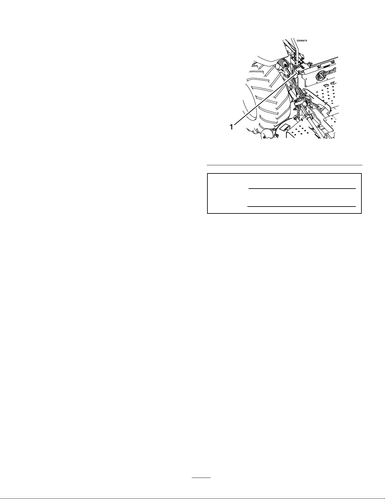
Figure1
1.Modelandserialnumberlocation
ModelNo.
SerialNo.
Wheneveryouneedservice,genuineExmarkparts,
oradditionalinformation,contactanAuthorized
ServiceDealerorExmarkCustomerServiceandhave
themodelandserialnumbersofyourproductready.
Figure1identiesthelocationofthemodelandserial
numbersontheproduct.Writethenumbersinthe
spaceprovided.
3
Page 4

Contents
Introduction...........................................................3
Safety.....................................................................5
SafetyAlertSymbol.........................................5
SafeOperatingPractices..................................5
SafetyandInstructionalDecals.....................11
Specications.......................................................15
ModelNumbers............................................15
Systems.........................................................15
Dimensions...................................................17
TorqueRequirements....................................17
ProductOverview................................................18
Operation.............................................................18
Controls........................................................18
Pre-Start........................................................19
OperatingInstructions..................................20
Transporting.................................................22
Maintenance.........................................................24
RecommendedMaintenanceSchedule(s)...........24
PeriodicMaintenance.......................................25
CheckEngineOilLevel.................................25
CheckBatteryCharge....................................25
CheckSafetyInterlockSystem.......................26
CheckRolloverProtectionsSystems(Roll
Bar)Pins...................................................27
CheckSeatBelt..............................................27
CheckforLooseHardware............................27
ServiceAirCleaner........................................27
ChangeEngineOil........................................27
CheckHydraulicOilLevel.............................27
CheckTirePressures.....................................28
CheckConditionOfBelts..............................28
LubricateGreaseFittings...............................28
LubricateRearCasterWheelHub(s)...............29
LubricateBrakeHandlePivot........................30
LubricateBrakeRodBushings.......................30
LubricateMotionControlBronze
Bushings...................................................30
LubricateMotionControlShaft.....................30
LubricateSteeringLinkageRodEnds.............30
CheckSparkPlugs.........................................30
ChangeHydraulicSystemFilter.....................31
CheckWheelHubLocknuts..........................31
ThreadLockingAdhesives.............................31
DielectricGrease...........................................32
Adjustments.....................................................32
PumpDriveBeltTension...............................32
PumpDriveBeltReplacement.......................32
ParkBrakeAdjustment..................................32
MotionControlLinkageAdjustment.............33
WeightTransferSpringAdjustment...............34
CasterPivotBearingsPre-Load
Adjustment...............................................35
ClutchShim..................................................35
Cleaning...........................................................37
CleanEngineCoolingSystem........................37
RemoveAccumulatedDebrisfrom
Engine(Briggs&StrattonUnits
Only).........................................................37
RemoveEngineShroudsandCleanCooling
Fins...........................................................38
WasteDisposal..............................................38
Troubleshooting...................................................39
Schematics...........................................................41
4
Page 5
Safety
Safety
SafetyAlertSymbol
ThisSafetyAlertSymbol(Figure2)isusedbothin
thismanualandonthemachinetoidentifyimportant
safetymessageswhichmustbefollowedtoavoid
accidents
Thissymbolmeans:ATTENTION!BECOME
ALERT!YOURSAFETYISINVOLVED!
Figure2
1.Safetyalertsymbol
Thesafetyalertsymbolappearsaboveinformation
whichalertsyoutounsafeactionsorsituations
andwillbefollowedbythewordDANGER,
WARNING,orCAUTION.
•Neverletchildrenoruntrainedpeopleoperate
orservicetheequipment.Localregulationsmay
restricttheageoftheoperator.
•Theowner/usercanpreventandisresponsible
foraccidentsorinjuriesoccurringtohimselfor
herself,otherpeopleorproperty.
Preparation
•Evaluatetheterraintodeterminewhataccessories
andattachmentsareneededtoproperlyand
safelyperformthejob.Onlyuseaccessoriesand
attachmentsapprovedbyExmark.
•Wearappropriateclothingincludingsafetyglasses,
substantialfootwear,longtrousers,andhearing
protection.DoNotoperatewhenbarefootor
whenwearingopensandals.Longhair,loose
clothingorjewelrymaygettangledinmoving
parts.
CAUTION
DANGER:Whitelettering/Redbackground.
Indicatesanimminentlyhazardoussituationwhich,if
notavoided,Willresultindeathorseriousinjury.
WARNING:Blacklettering/Orangebackground.
Indicatesapotentiallyhazardoussituationwhich,if
notavoided,Couldresultindeathorseriousinjury.
CAUTION:Blacklettering/Y ellowbackground.
Indicatesapotentiallyhazardoussituationwhich,if
notavoided,Mayresultinminorormoderateinjury.
Thismanualusestwootherwordstohighlight
information.Importantcallsattentiontospecial
mechanicalinformationandNoteemphasizes
generalinformationworthyofspecialattention.
SafeOperatingPractices
Training
•ReadtheOperator’sManualandothertraining
material.Iftheoperator(s)ormechanic(s)can
notreadEnglishitistheowner’sresponsibilityto
explainthismaterialtothem.
Thismachineproducessoundlevelsin
excessof85dBAattheoperator’searand
cancausehearinglossthroughextended
periodsofexposure.
Wearhearingprotectionwhenoperatingthis
machine.
•Inspecttheareawheretheequipmentistobe
usedandremoveallrocks,toys,sticks,wires,
bones,andotherforeignobjectswhichcanbe
thrownbythemachineandmaycausepersonal
injurytotheoperatororbystanders.
•Becomefamiliarwiththesafeoperationofthe
equipment,operatorcontrols,andsafetysigns.
•Alloperatorsandmechanicsshouldbetrained.
Theownerisresponsiblefortrainingtheusers.
5
Page 6

Safety
DANGER
Incertainconditionsgasolineisextremely
ammableandvaporsareexplosive.
Areorexplosionfromgasolinecanburn
you,others,andcausepropertydamage.
•Fillthefueltankoutdoorsinanopen
area,whentheengineiscold.Wipeup
anygasolinethatspills.
•Neverrellthefueltankordrainthe
machineindoorsorinsideanenclosed
trailer.
•DoNotllthefueltankcompletely
full.Addgasolinetothefueltankuntil
thelevelis1/4to1/2inch(6–13mm)
belowthebottomofthellerneck.This
emptyspaceinthetankallowsgasoline
toexpand.
•Neversmokewhenhandlinggasoline,
andstayawayfromanopenameor
wheregasolinefumesmaybeignitedby
spark.
•Storegasolineinanapprovedcontainer
andkeepitoutofthereachofchildren.
•Addfuelbeforestartingtheengine.
Neverremovethecapofthefueltankor
addfuelwhenengineisrunningorwhen
theengineishot.
•Iffuelisspilled,DoNotattempttostart
theengine.Moveawayfromtheareaof
thespillandavoidcreatinganysourceof
ignitionuntilfuelvaporshavedissipated.
•DoNotoperatewithoutentireexhaust
systeminplaceandinproperworking
condition.
DANGER
Incertainconditionsduringfueling,static
electricitycanbereleasedcausingaspark
whichcanignitegasolinevapors.Areor
explosionfromgasolinecanburnyouand
othersandcausepropertydamage.
•Alwaysplacegasolinecontainersonthe
groundawayfromyourvehiclebefore
lling.
•DoNotllgasolinecontainersinsidea
vehicleoronatruckortrailerbedbecause
interiorcarpetsorplastictruckbedliners
mayinsulatethecontainerandslowthe
lossofanystaticcharge.
•Whenpractical,removegas-powered
equipmentfromthetruckortrailerand
refueltheequipmentwithitswheelson
theground.
•Ifthisisnotpossible,thenrefuelsuch
equipmentonatruckortrailerfroma
portablecontainer,ratherthanfroma
gasolinedispensernozzle.
•Ifagasolinedispensernozzlemustbe
used,keepthenozzleincontactwiththe
rimofthefueltankorcontaineropening
atalltimesuntilfuelingiscomplete.
WARNING
Gasolineisharmfulorfatalifswallowed.
Long-termexposuretovaporshascaused
cancerinlaboratoryanimals.Failuretouse
cautionmaycauseseriousinjuryorillness.
•Avoidprolongedbreathingofvapors.
•Keepfaceawayfromnozzleandgas
tank/containeropening.
•Keepawayfromeyesandskin.
•Neversiphonbymouth.
•Checkthattheoperator’spresencecontrols,
safetyswitches,andshieldsareattachedand
functioningproperly .DoNotoperateunlessthey
arefunctioningproperly.
6
Page 7

Safety
Operation
WARNING
Operatingengineparts,especiallythe
mufer,becomeextremelyhot.Severeburns
canoccuroncontactanddebris,suchas
leaves,grass,brush,etc.cancatchre.
•Allowengineparts,especiallythemufer,
tocoolbeforetouching.
•Removeaccumulateddebrisfrommufer
andenginearea.
•Installandmaintaininworkingordera
sparkarresterbeforeusingequipment
onforest-covered,grass-covered,or
brush-coveredunimprovedland.
WARNING
Engineexhaustcontainscarbonmonoxide,
whichisanodorlessdeadlypoisonthatcan
killyou.
•Besurealldrivesareinneutralandparkingbrake
isengagedbeforestartingengine.Useseatbelts
withtherollbarintheraisedandlockedposition.
•Neveroperatethemowerwithdamagedguards,
shields,orcovers.Alwayshavesafetyshields,
guards,switchesandotherdevicesinplaceandin
properworkingcondition.
•Nevermowwiththedischargedeectorraised,
removedoralteredunlessthereisagrass
collectionsystemormulchkitinplaceand
workingproperly .
•DoNotchangetheenginegovernorsettingor
overspeedtheengine.
•Stopengine,waitforallmovingpartstostop,
removekeyandengageparkingbrake:
–Beforechecking,cleaningorworkingonthe
mower.
–Afterstrikingaforeignobjectorabnormal
vibrationoccurs(inspectthemowerfor
damageandmakerepairsbeforerestarting
andoperatingthemower).
–Beforeclearingblockages.
DoNotrunengineindoorsorinasmall
connedareawheredangerouscarbon
monoxidefumescancollect.
WARNING
OperatingaFrontRunnertractorwithoutan
approvedExmarkfrontmountattachment
increasesthepossibilityofforwardtipover.
Tip-overcouldcauseseriousinjuryordeath.
WhenoperatingaFrontRunnertractor
withoutanapprovedExmarkfrontmount
attachment,observethefollowing:
•Limitoperationtominimumrequiredto
installadifferentfrontmountattachment.
•Minimizespeedanduseextremecaution.
•Onlyoperateonaatlevelsurface.
•DoNotoperateupordownatrailerramp.
•Avoidsuddenaccelerationordeceleration.
–Wheneveryouleavethemower.
•Stopengine,waitforallmovingpartstostop,and
engageparkingbrake:
–Beforerefueling.
–Beforedumpingthegrasscatcher.
WARNING
Hands,feet,hair,clothing,oraccessoriescan
becomeentangledinrotatingparts.Contact
withtherotatingpartscancausetraumatic
amputationorseverelacerations.
•DoNotoperatethemachinewithout
guards,shields,andsafetydevicesin
placeandworkingproperly.
•Keephands,feet,hair,jewelry,orclothing
awayfromrotatingparts.
•NEVERcarrypassengers.DONOToperate
themowerwhenpeople,especiallychildren,or
petsareinthearea.
•Operateonlyindaylightorgoodarticiallight,
keepingawayfromholesandhiddenhazards.
•Bealert,slowdownandusecautionwhenmaking
turns.Lookbehindandtothesidebefore
changingdirections.
7
Page 8
Safety
•Stoptheblades,slowdown,andusecautionwhen
crossingsurfacesotherthangrassandwhen
transportingthemowertoandfromtheareato
bemowed.
•Beawareofthemowerdischargepathanddirect
dischargeawayfromothers.
•DoNotoperatethemowerundertheinuence
ofalcoholordrugs.
•Useextremecarewhenloadingorunloadingthe
machineintoatrailerortruck.
•Usecarewhenapproachingblindcorners,shrubs,
trees,orotherobjectsthatmayobscurevision.
SlopeOperation
UseExtremecautionwhenmowingand/orturning
onslopesaslossoftractionand/ortip-overcould
occur.Theoperatorisresponsibleforsafeoperation
onslopes.
DANGER
Operatingonwetgrassorsteepslopescan
causeslidingandlossofcontrol.Wheels
droppingoveredges,ditches,steepbanks,or
watercancauserollovers,whichmayresult
inseriousinjury,deathordrowning.
•DoNotmowslopeswhengrassiswet.
•DoNotmowneardrop-offsornearwater.
•DoNotmowslopesgreaterthan15
degrees.
•Reducespeedanduseextremecaution
onslopes.
•Avoidsuddenturnsorrapidspeed
changes.
•Keeptherollbarintheraisedandlocked
positionanduseseatbelt.
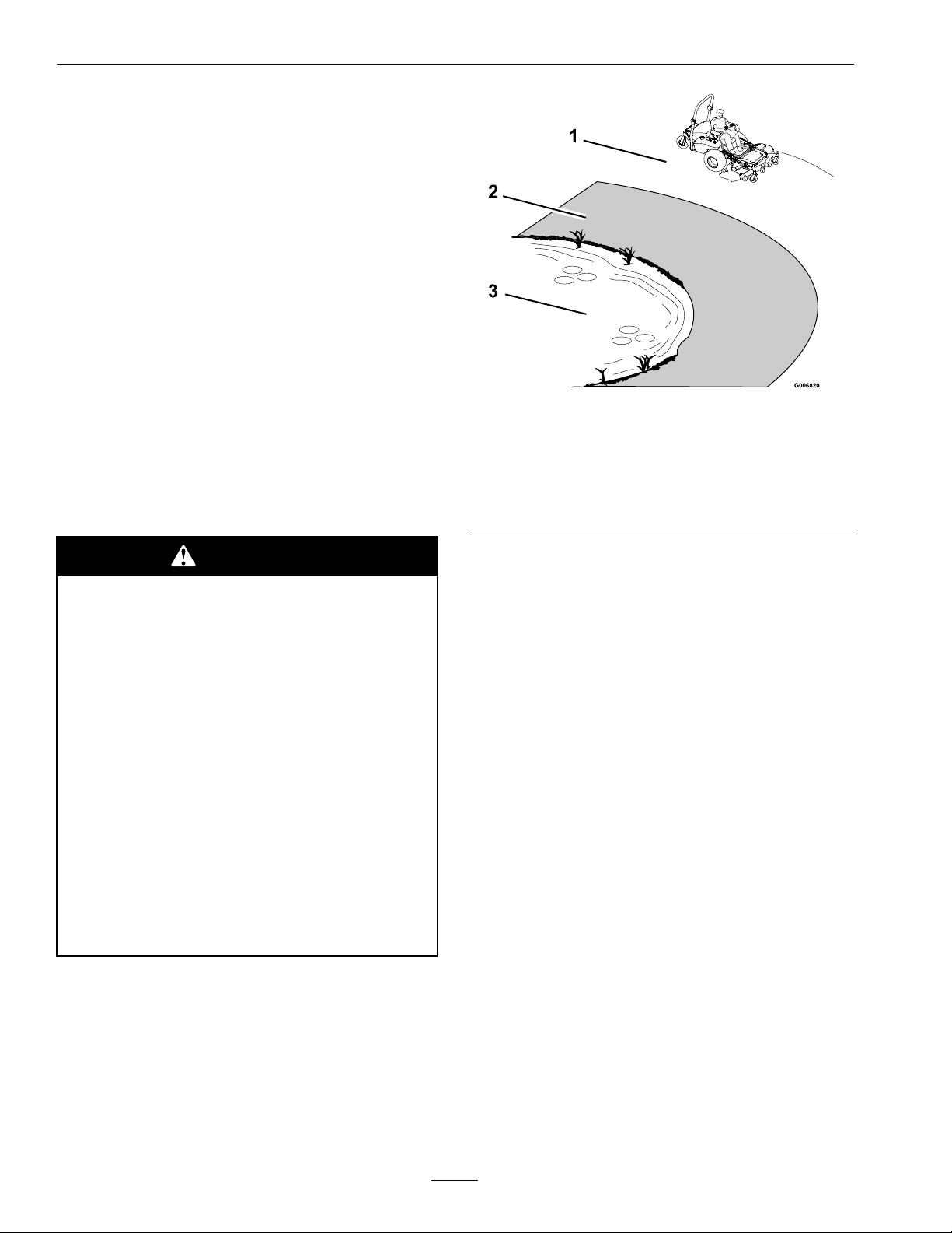
Figure3
1.SafeZone-Usethemowerhereonslopeslessthan15
degrees
2.DangerZone-Useawalkbehindmowerand/orhand
trimmeronslopesgreaterthan15degrees,near
drop-offsandwater.
3.Water
•Removeormarkobstaclessuchasrocks,tree
limbs,etc.fromthemowingarea.Tallgrasscan
hideobstacles.
•Watchforditches,holes,rocks,dipsandrisesthat
changetheoperatingangle,asroughterraincould
overturnthemachine.
•Avoidsuddenstopswhenmowingdownhill
becausethemowermaytipforwards.
•Beawarethatoperatingonwetgrass,acrosssteep
slopesordownhillmaycausethemowertolose
traction.Lossoftractiontothedrivewheelsmay
resultinslidingandlossofbrakingandsteering.
•Alwaysavoidsuddenstartingorstoppingona
slope.Iftireslosetraction,disengagetheblades
andproceedslowlyofftheslope.
•Followthemanufacturer’srecommendationsfor
wheelweightsorcounterweightstoimprove
stability.
•Seeinsidethebackcovertodeterminethe
approximateslopeangleoftheareatobemowed.
•Useawalkbehindmowerand/orahandtrimmer
neardrop-offs,ditches,steepbanksorwater.
(Figure3).
•Useextremecarewithgrasscatchersor
attachments.Thesecanchangethestabilityofthe
machineandcauselossofcontrol.
UsingtheRolloverProtectionSystem
(ROPS)
ARolloverProtectionSystem(rollbar)isinstalled
ontheunit.
8
Page 9

Safety
WARNING
Thereisnorolloverprotectionwhentheroll
barisdown.Wheelsdroppingoveredges,
ditches,steepbanks,orwatercancause
rollovers,whichmayresultinseriousinjury,
deathordrowning.
•Keeptherollbarintheraisedandlocked
positionanduseseatbelt.
•Lowertherollbaronlywhenabsolutely
necessary.
•DoNotwearseatbeltwhentherollbar
isdown.
•Driveslowlyandcarefully.
•Raisetherollbarassoonasclearance
permits.
•Checkcarefullyforoverheadclearances(i.e.
branches,doorways,andelectricalwires)before
drivingunderanyobjectsandDoNotcontact
them.
•Carefullyreleasepressurefromcomponentswith
storedenergy.
•Disconnectbatteryorremovesparkplugwire
beforemakinganyrepairs.Disconnectthe
negativeterminalrstandthepositivelast.
Reconnectpositiverstandnegativelast.
•Usecarewhencheckingblades.Wraptheblade(s)
orweargloves,andusecautionwhenservicing
them.Onlyreplacedamagedblades.Never
straightenorweldthem.
•Keephandsandfeetawayfrommovingparts.
Ifpossible,DoNotmakeadjustmentswiththe
enginerunning.
•Chargebatteriesinanopenwellventilatedarea,
awayfromsparkandames.Unplugcharger
beforeconnectingordisconnectingfrombattery.
Wearprotectiveclothinganduseinsulatedtools.
•Keepallguards,shieldsandallsafetydevicesin
placeandinsafeworkingcondition.
•Checkallboltsfrequentlytomaintainproper
tightness.
•Intheeventofarollover,taketheunittoan
AuthorizedServiceDealertohavetheROPS
inspected.
MaintenanceandStorage
•Disengagedrives,lowerimplement,setparking
brake,stopengineandremovekeyordisconnect
sparkplugwire.Waitforallmovementtostop
beforeadjusting,cleaningorrepairing.
•Keepengine,enginearea,andpumpdrivebelt
compartmentfreefromaccumulationofgrass,
leaves,excessivegreaseoroil,andotherdebris
whichcanaccumulateintheseareas.These
materialscanbecomecombustibleandmayresult
inare.
•LetenginecoolbeforestoringandDoNotstore
nearameoranyenclosedareawhereopenpilot
lightsorheatappliancesarepresent.
•Shutofffuelwhilestoringortransporting.Do
Notstorefuelnearamesordrainindoors.
•Frequentlycheckforwornordeteriorating
componentsthatcouldcreateahazard.
•Allreplacementpartsmustbethesameas
orequivalenttothepartssuppliedasoriginal
equipment.
•Parkmachineonlevelground.Neverallow
untrainedpersonneltoservicemachine.
•Usejackstandstosupportcomponentswhen
required.
9
Page 10

Safety
WARNING
Hydraulicuidescapingunderpressure
canpenetrateskinandcauseinjury.Fluid
accidentallyinjectedintotheskinmustbe
surgicallyremovedwithinafewhoursbya
doctorfamiliarwiththisformofinjuryor
gangrenemayresult.
•Makesureallhydraulicuidhoses
andlinesareingoodconditionand
allhydraulicconnectionsandttings
aretightbeforeapplyingpressureto
hydraulicsystem.
•Keepbodyandhandsawayfrompinhole
leaksornozzlesthatejecthighpressure
hydraulicuid.
•Usecardboardorpaper,notyourhands,
tondhydraulicleaks.
•Safelyrelieveallpressureinthehydraulic
systembyplacingthemotioncontrol
leversinneutralandshuttingoffthe
enginebeforeperforminganyworkon
thehydraulicsystem.
10
Page 11
SafetyandInstructionalDecals
Safety
•Keepallsafetysignslegible.Removeallgrease,
dirtanddebrisfromsafetysignsandinstructional
labels.
•Replaceallworn,damaged,ormissingsafety
signs.
•Whenreplacementcomponentsareinstalled,be
surethatcurrentsafetysignsareafxedtothe
replacedcomponents.
•Ifanattachmentoraccessoryhasbeeninstalled,
makesurecurrentsafetysignsarevisible.
1-513747
•Newsafetysignsmaybeobtainedfrom
yourauthorizedExmarkequipmentdealeror
distributororfromExmarkMfg.Co.Inc.
•Safetysignsmaybeafxedbypeelingoffthe
backingtoexposetheadhesivesurface.Apply
onlytoaclean,drysurface.Smoothtoremove
anyairbubbles.
•Familiarizeyourselfwiththefollowingsafetysigns
andinstructionlabels.Theyarecriticaltothesafe
operationofyourExmarkcommercialmower.
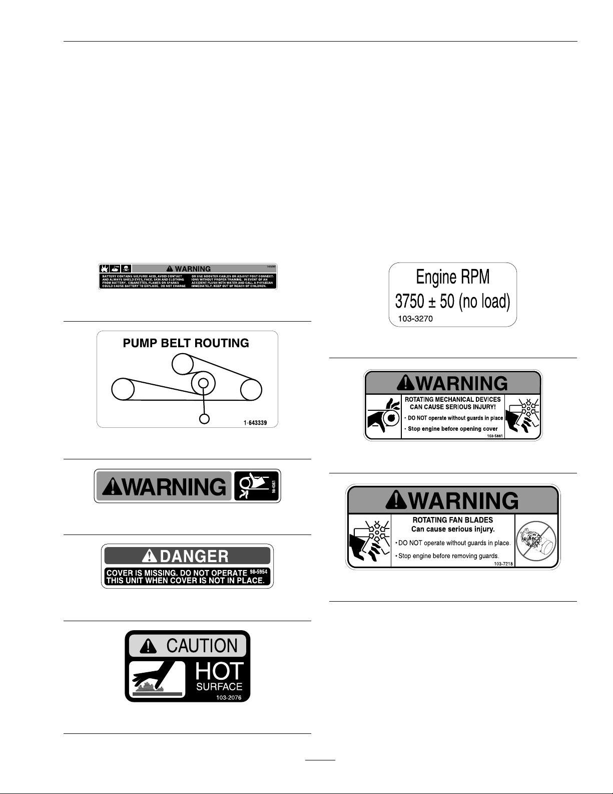
103-3270
1-643339
103-5881
98-4361
103-7218
98-5954
103-2076
11
Page 12
Safety
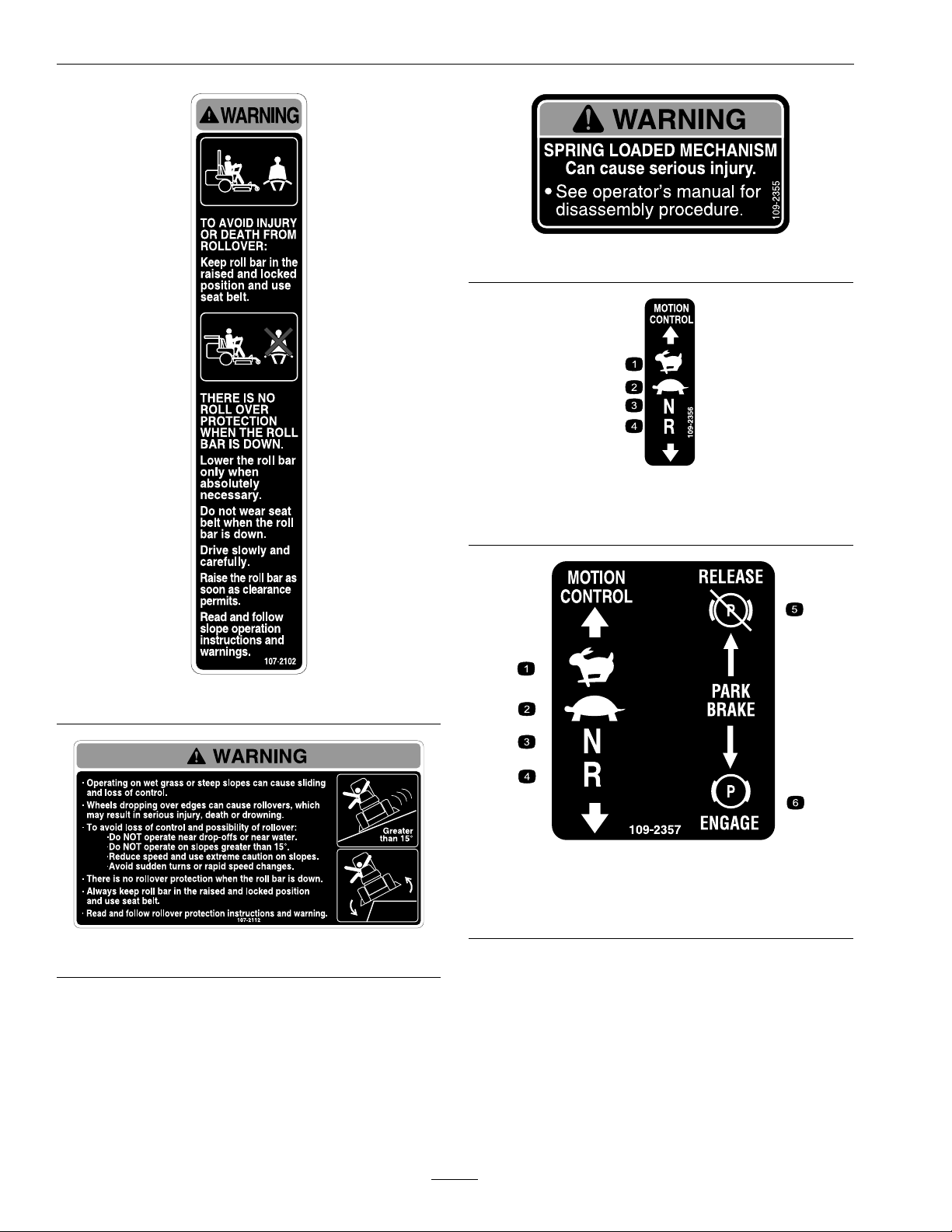
109-2355
109-2356
1.Fast3.Neutral
2.Slow
4.Reverse
107-2102
107-2112
109-2357
1.Fast4.Reverse
2.Slow
3.Neutral6.ParkBrake—Engage
5.ParkBrake—Release
12
Page 13
Safety
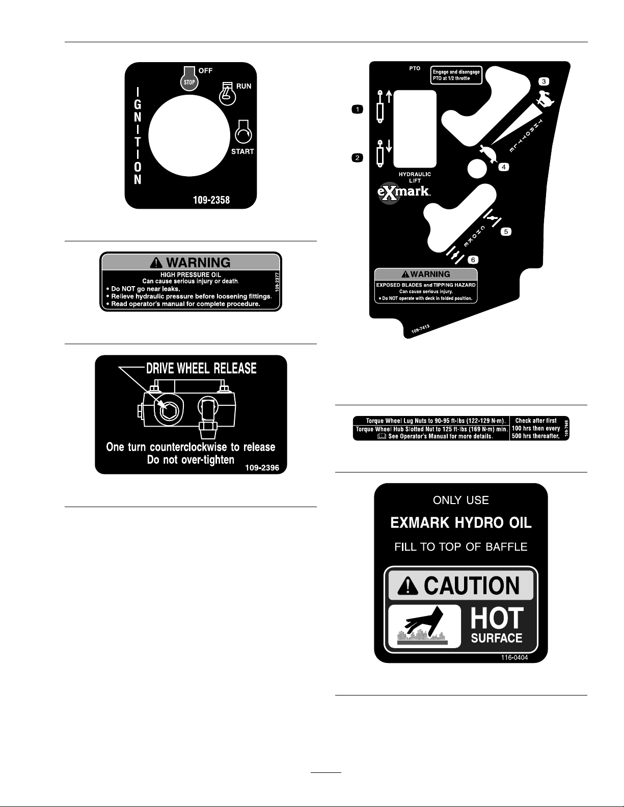
109-2358
109-2377
109-7413
1.Cylinder—extend4.Slow
2.Cylinder—retract5.Choke—on
3.Fast
109-2396
6.Choke—off
109-7949
116-0404
13
Page 14
Safety
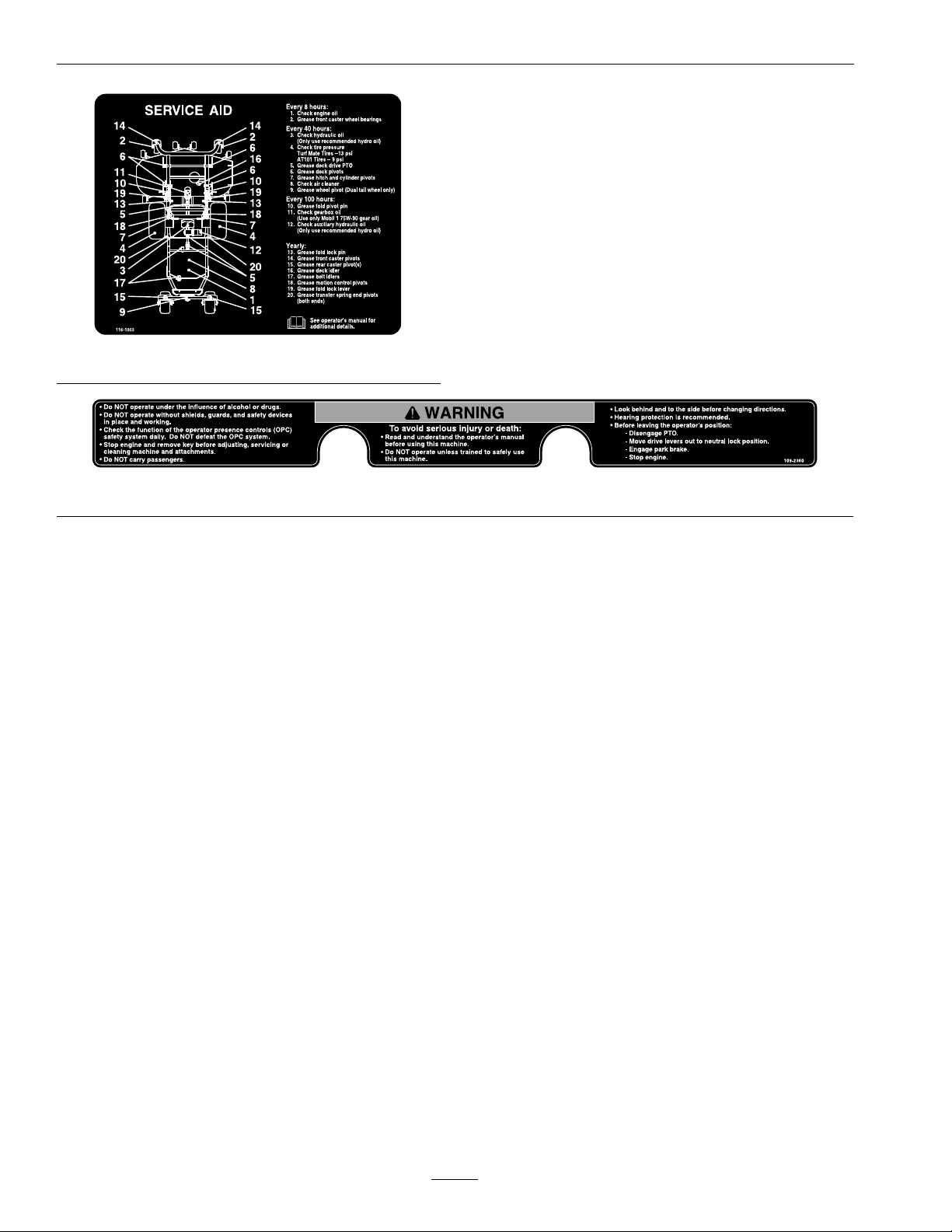
116-1003
109-2360
14
Page 15

Specications
ModelNumbers
SerialNos:790,000andHigher
FR27KC;FR31BV
Specications
Systems
Engine
•EngineSpecications:SeeyourEngineOwner’s
Manual
•RPM:FullSpeed:3750±50RPM(NoLoad)
Idle:1500RPM
FuelSystem
•Capacity:8.5gal.(32L)
•TypeofFuel:Regularunleadedgasoline,87
octaneorhigher.
•FuelFilter:
–Kohler:
In-line15MicronKohlerP/N2405010.
–Briggs&Stratton:
In-line30MicronBriggsP/N695327.
•FuelShut-OffValve:1/4turnincrements(“ON”,
“OFF”).
•Fuelgaugeinrighthandfueltank.
ElectricalSystem
•ChargingSystem:FlywheelAlternator
•ChargingCapacity:
–Kohler:15amps
–Briggs&Stratton:20amps
•BatteryType:BCIGroupU1
•BatteryVoltage:12Volt
•Polarity:NegativeGround
•Fuses:
–Kohler:
One15ampandtwo20ampbladetype
–Briggs&Stratton:
One15amp,one20amp,andone30amp
bladetype
SafetyInterlockSystem
•PTOmustbedisengaged,brakeengaged,and
motioncontrolleversout(neutrallock)tostart
engine.(Itisnotnecessaryfortheoperatortobe
intheseattostarttheengine.)
•OperatormustbeinseatwhenPTOisengaged,
brakeisdisengaged,ormotioncontrolleversare
movedinorenginewillstop.
•Enginewillstopifthemotioncontrollevers
aremovedfromneutralpositionwhilebrakeis
engaged.
OperatorControls
•SteeringandMotionControl:
Note:Motioncontrolleversareadjustableto
threeheights.
–Separatelevers,oneachsideoftheconsole,
controlspeedanddirectionoftravelofthe
respectivedrivewheels.
–Steeringiscontrolledbyvaryingtheposition
oftheleversrelativetoeachother.
–Movingmotioncontrolleversoutward(in
slots)locksthedrivesysteminneutral.
•PTOEngagementLever:EngagesdrivetoPTO
(mowerdeck).
•ParkingBrakeLever:Engagesparkingbrakeby
pullingback.
Seat
•Type:Standardseatwithhighback,foampadded
(internalsuspension)andarmrestsandintegral
safetyswitch.
Optionalseataccessories:
–Customridesuspensionsystemtoenhance
StandardSeat.
–Deluxesuspensionseatwithhighback,low
prolefoam-in-placecushion(dampened,
adjustablespringsuspension)andarmrests.
15
Page 16

Specications
•Mounting:Hingedtotiltupforaccessto
hydraulicpumps,batteryandothercomponents.
Theseatisheldinthetiltedpositionwitha
linkage.Adjustableforeandaftseattrack.
•Armrests:Standardseat:foampaddedip-up
armrests.Optionalsuspensionseat:molded
adjustableip-uparmrests.
•SeatSafetySwitch:Internaltothebottomseat
cushion,nonserviceable.Timedelaymodule
incorporatedintotheSafetyInterlockSystem
eliminatesroughgroundcut-outs.
HydrostaticGroundDriveSystem
•HydrostaticPumps:TwoHydroGearPR16cc
variabledisplacementpistonpumps.
•WheelMotors:HydroGearplanetaryreduction
motors.
•HydraulicOilType:UseExmarkPremiumHydro
oil.
•HydraulicOilCapacity:5.2qt.(4.9L)
•HydraulicFilter:Replaceablecartridgetype.
P/N103-2146:25microns,Nobypass
•Speeds:
0-10.5mph(16.9km/hr)forward
0-6.6mph(10.6km/hr)reverse
•Drivewheelreleasevalvesallowmachinetobe
movedwhenengineisnotrunning.
Tires&Wheels
Drive
Pneumatic
(Air-Filled)
Quantity
TreadAT101
Size24x
PlyRating
Pressure
222
12.00-12
4
9psi
(62kPa)
Front
Caster
SemiPneumatic
SmoothSmooth
9x3.50-413x6.5-6
CuttingDeck
(SoldSeparately)
•ModelNumbers:
–FR524
–FR604
–FR724
•CuttingWidth:
–52inch(132cm)
–60inch(152cm)
–72inch(183cm)
•Discharge:Side
•BladeSize:(3ea.)
–52inchDeck:18.00inches(45.7cm)
RearCaster
(DualTail
Wheel)
SemiPneumatic
–60inchDeck:20.50inches(52.1cm)
–72inchDeck:24.50inches(62.2cm)
•BladeSpindles:Solidsteelspindleswith13/4
inch(4.45cm)I.D .bearings.
•DeckDrive:“B”-Sectionbeltfromjackshafton
decktobladespindles.
•Deck:Fulloatingdeckisattachedtoout-front
supportframe,removableforservice.Six
anti-scalprollersprovidemaximumturf
protection.Deckdesignallowsforbagging,
mulchingorsidedischarge.
•DeckDepth:
–52inchDeck:5.5inches(14.0cm)
–60inchDeck:5.5inches(14.0cm)
–72inchDeck:5.5inches(14.0cm)
16
Page 17

Specications
•CuttingHeightAdjustment:Adjustsfrom11/2
inches(3.8cm)to5inches(12.7cm)innitely
variable.
•MulchingKit:Optional
•Bagger:Optional
Dimensions
OverallWidth:
Without
Deck
Deector
Up
Deector
Down
OverallLength:
Withoutdeckandoor
panfolded
52inch
Deck
49.0inches
(124.5cm)
53.3inches
(135.4cm)
64.0inches
(163cm)
60inch
Deck
49.0inches
(124.5cm)
61.4inches
(156cm)
72.0inches
(183cm)
27HPKohler&31HP
Briggs&Stratton
82.3inches(209.0cm)
72inch
Deck
53.0inches
(135cm)
73.4inches
(186cm)
84.3inches
(214cm)
MinimumTurningRadius
55.25inches(140.3cm)
CurbWeight:
Withoutdeck911lb(413kg)
52inchDeck
60inchDeck
72inchDeck
1303lb(591kg)
1348lb(611kg)
1397lb(634kg)
TorqueRequirements
BoltLocation
EngineMountingBolts
WheelLugNuts
WheelMotorMounting
Bolts
WheelHubLockNut210-250ft-lb
RolloverProtectionSystem
(RollBar)MountingBolts
ClutchRetainingBolt
(securedwiththreadlocker)
Torque
30-35ft-lb(41-47N-m)
90-95ft-lb(122-129N-m)
72-77ft-lb(98-104N-m)
(285-339N-m)
30-35ft-lb(41-47N-m)
55-60ft-lb(75-81N-m)
52inchDeck114.3inches(290.3cm)
60inchDeck114.3inches(290.3cm)
72inchDeck114.3inches(290.3cm)
OverallHeight:
RollBar-UpRollBar-Down
69.2inches(175.8cm)50.7inches(128.8cm)
TreadWidth:(CentertoCenterof
Tires,Widthwise)
52inchDeck60inchDeck72inchDeck
41.4inches
(105.2cm)
41.4inches
(105.2cm)
45.4inches
(115.3cm)
WheelBase:(CenterofCasterTireto
CenterofDriveTire)
51.2inches(130.0cm)
17
Page 18

Operation
ProductOverview
Figure4
1.FuelCap4.SeatBelt
2.RollBar
3.Controls
5.MotionControlLever
6.ParkingBrakeLever
Operation
Note:Determinetheleftandrightsidesofthe
machinefromthenormaloperatingposition.
Controls
MotionControlLevers
Themotioncontrolleverslocatedoneachsideofthe
consolecontroltheforwardandreversemotionof
themachine.Theleverscontroltheowofhydraulic
oilfromthehydrostaticpumptothedrivewheel
motorforeachside.
Movingtheleversforwardorbackwardturnsthe
wheelonthesamesideforwardorinreverse.Wheel
speedisproportionaltotheamounttheleveris
moved.
Movingtheleversoutwardfromthecenterposition
intotheT-slotlocksthemintheneutralposition
(Figure6).
ChokeControl
Locatedonrightfueltankconsole.
Thechokeisusedtoaidinstartingacoldengine.
Movingthechokeleverforwardwillputthechokein
the“ON”positionandmovingthechokelevertothe
rear,tothedetent,willputthechokeinthe“OFF”
position.DoNotrunawarmenginewithchokein
the“ON”position.
ThrottleControl
Locatedonrightfueltankconsole.
Thethrottleisusedtocontrolenginespeed.Moving
thethrottleleverforwardwillincreaseenginespeed
andmovingthethrottlelevertotherearwilldecrease
enginespeed.Movingthethrottleforwardintothe
detentisfullthrottle.
ParkBrakeLever
Locatedonleftsideofunit,betweentheseatandthe
dummytank.
Thebrakeleverengagesaparkingbrakeonthedrive
wheels.
Pulltheleverupandrearwardtoengagethebrake.
18
Page 19

Operation
Pushtheleverforwardanddowntodisengagethe
brake.
Theunitmustbetieddownandbrakeengagedwhen
transporting.
IgnitionSwitch
Locatedonrightfueltankconsole.
Theignitionswitchisusedtostartandstopthe
engine.Theswitchhasthreepositions“OFF”,“ON”
and“START”.Insertkeyintoswitchandrotate
clockwisetothe“ON”position.Rotateclockwiseto
thenextpositiontoengagethestarter(keymustbe
heldagainstspringpressureinthisposition).
Note:Brakemustbeengaged,motioncontrollevers
out(neutrallockposition),andPTOswitch“OFF”
tostartengine.(Itisnotnecessaryfortheoperator
tobeintheseattostarttheengine.)
HourMeter
Locatedontherightfueltankconsole.
Thehourmeterisconnectedtoapressureswitch
installedintheengineblockanditrecordsthe
numberofhoursthattheenginehasrun.Ifthe
ignitionswitchisleftonwithoutenginerunning,
hourmeterwillnotrun.
Note:Thisswitchisnotalowoilsensorandwillnot
alerttheoperatoriftheengineoilislow .
DriveWheelReleaseValves
Locatedonthetopleftfrontcornerofhydrostatic
pumps.
Drivewheelreleasevalvesareusedtoreleasethe
hydrostaticdrivesystemtoallowthemachinetobe
pushedwithouttheenginerunning.
Witha5/8inchwrench,turnbothvalvesoneturn
counterclockwisetoreleasedrivesystem.Turn
clockwisetoresetsystem.DoNotovertighten.Do
Nottowmachine.
PTOEngagementSwitch
Locatedonrightfueltank.
Switchmustbepulledouttothe“ROTATE”
positiontoengagetheblades.Switchispushedinto
the“STOP”positiontostoptheblades.
HydraulicLiftSwitch
Locatedonrightfueltankconsole.
Thehydraulicliftswitchisusedtoraiseandlower
themowerdeck.
Pushthefrontportionofthehydraulicliftswitch
downtoraisethemowerdecktothedesiredheight.
Pushtherearportionofthehydraulicliftswitch
downtolowerthemowerdecktothedesiredheight.
FuelShut-OffValve
Locatedinfuellinebyfueltankandfuellter.
Thefuelshut-offvalveisusedtoshutoffthefuel
whenthemachinewillnotbeusedforafewdays,
duringtransporttoandfromthejobsite,andwhen
parkedinsideabuilding.
Rotatethevalve1/4turnclockwisetoshutofffuel.
Rotatethevalve1/4turncounterclockwisetoturn
onfuel.
FuelGauge
Locatedattherearoftherightfueltank.
Thefuelgaugemonitorstheamountoffuelinthe
rightfueltankonly .Thelefttankdoesnotholdfuel.
Pre-Start
Fillfueltanks.Forbestresultsuseonlyclean,fresh
regulargradeunleadedgasolinewithanoctanerating
of87orhigher.Regulargradeleadedgasolinemay
alsobeused;however,combustionchamberand
cylinderheadwillrequiremorefrequentservice.See
EngineOwner’sManual.
DoNotaddoiltogasoline.
DoNotoverllfueltank.Neverllthefueltankso
thatthefuellevelrisesabovealevelthatis1/2inch
(13mm)belowthebottomofthellernecktoallow
forfuelexpansionandpreventfuelspillage.
Makesureyouunderstandthecontrols,their
locations,theirfunctions,andtheirsafety
requirements.
19
Page 20

Operation
RefertotheMaintenancesectionandperformallthe
necessaryinspectionandmaintenancesteps.
OperatingInstructions
RaisetheRolloverProtectionSystem
(ROPS)
Important:Lowertherollbaronlywhen
absolutelynecessary.
1.Removethehairpincotterpinsandremovethe
tworollbarpins(Figure5).
2.Raisetherollbartotheuprightpositionand
installthetwopinsandsecurethemwiththe
hairpincotterpins(Figure5).
Important:Alwaysusetheseatbeltwiththe
rollbarintheraisedposition.Ensurethatthe
rearpartoftheseatissecuredwiththeseat
latch.
StartingtheEngine
1.Movethemotioncontrolleversouttotheneutral
lockposition.
2.Pullupandbackontheparkingbrakeleverto
engagetheparkingbrake.
3.PushinonthePTOswitchtothe“STOP”
position.
Note:Itisnotnecessaryfortheoperatortobe
intheseattostarttheengine.
4.Placethethrottlemidwaybetweenthe“SLOW”
and“FAST”positions.
5.Onacoldengine,pushthechokeleverforward
intothe“ON”position.
Onawarmengine,leavethechokeinthe“OFF”
position.
6.Turnignitionswitchtothe“START”position.
Releasetheswitchassoonastheenginestarts.
Important:DoNotcranktheengine
continuouslyformorethantensecondsata
time.Iftheenginedoesnotstart,allowa60
secondcool-downperiodbetweenstarting
attempts.Failuretofollowtheseguidelines
canburnoutthestartermotor.
Figure5
1.Rollbar3.Pin
2.Raisedposition4.Hairpincotterpin
OpentheFuelShut-OffValve
Thefuelshut-offvalveislocatedontherightsideof
unitinfuellinenexttothefuellter.Raisetherear
hoodtoaccessfuelshut-offvalve.
7.Ifthechokeisinthe“ON”position,gradually
returnchoketothe“OFF”positionastheengine
warmsup.
EngagingthePTO
DANGER
Therotatingbladesunderthemowerdeck
aredangerous.Bladecontactcancause
seriousinjuryorkillyou.
DoNotputhandsorfeetunderthemower
ormowerdeckwhenthebladesareengaged.
20
Page 21

Operation
DANGER
Anuncovereddischargeopeningwillallow
objectstobethrowninanoperator’sor
bystander’sdirection.Also,contactwiththe
bladecouldoccur.Thrownobjectsorblade
contactcancauseseriousinjuryordeath.
Neveroperatethemowerwiththedischarge
deectorraised,removed,oralteredunless
thereisagrasscollectionsystemormulch
kitinplaceandworkingproperly.
ThePTOpush-pullswitchengagesthecuttingblades.
Besurethatallpersonsareclearofthemowerdeck
anddischargeareabeforeengagingPTO.
Important:Operatormustbeinseatbeforethe
PTOcanbeengaged.
1.Setthethrottletothe“MIDWAY”position.
2.PullthePTOswitchoutwardtothe“ROTATE”
position.
3.Placethethrottleinthe“FAST”positiontobegin
mowing.
DrivingtheMachine
CAUTION
Machinecanspinveryrapidlybypositioning
onelevertoomuchaheadoftheother.
Operatormaylosecontrolofthemachine,
whichmaycausedamagetothemachine
orinjury.
•Usecautionwhenmakingturns.
•Slowthemachinedownbeforemaking
sharpturns.
Important:Tobeginmovement(forwardor
backward)theoperatormustbeintheseat,the
brakelevermustbedisengaged(pusheddown)
beforethemotioncontrolleverscanbemovedin
ortheenginewillstop.
WhenleversarecenteredintheT-slotthedrive
systemisintheneutralposition.Withleversmoved
outintheT-slotthedrivesystemisintheneutrallock
position(Figure6).
DisengagingthePTO
1.Setthethrottletothe“MIDWAY”position.
2.PushthePTOswitchintothe“STOP”position
todisengagetheblades.
StoppingtheEngine
1.Bringtheunittoafullstop.
2.DisengagethePTO.
3.Movethemotioncontrolleversouttotheneutral
lockposition.
4.Engagetheparkingbrake.
5.Placethethrottlemidwaybetweenthe“SLOW”
and“FAST”positions.
6.Allowtheenginetorunforaminimumof15
seconds,thenturntheignitionswitchtothe
“OFF”positiontostoptheengine.
7.Removethekeytopreventchildrenorother
unauthorizedpersonsfromstartingengine.
8.Closethefuelshut-offvalvewhenthemachine
willnotbeinuseforafewdays,when
transporting,orwhentheunitisparkedinside
abuilding.
Figure6
1.HandlesOut(Neutral
Lock)
2.HandlesIn(Neutral)
3.FrontofUnit
4.Forward
5.Neutral
6.Reverse
7.NeutralLock
DrivingForward
1.Releasetheparkingbrake.
2.Movethemotioncontrolleversinwardtothe
centertotheneutralunlockedposition.
21
Page 22

Operation
3.Tomoveforwardinastraightlineapplyequal
forwardpressuretobothlevers.
Toturnleftorright,pullthemotioncontrollever
backtowardneutralinthedirectiondesired.
Themachinewillmovefasterthefartherthe
motioncontrolleversaremovedawayfrom
neutral.
4.Tostop,pullthemotioncontrolleversbackto
theneutralposition.
Transporting
TransportingaUnit
Important:DoNottransportFrontRunner
tractorwithoutanapprovedExmarkfrontmount
attachment.
Useaheavy-dutytrailerortrucktotransportthe
machine.Lockbrakeandblockwheels.Securely
fastenthemachinetothetrailerortruckwithstraps,
chains,cable,orropes.Besurethatthetrailerortruck
hasallnecessarylightingandmarkingasrequiredby
law .Secureatrailerwithasafetychain.
CAUTION
Thisunitdoesnothaveproperturn
signals,lights,reectivemarkings,ora
slowmovingvehicleemblem.Drivingona
streetorroadwaywithoutsuchequipment
isdangerousandcanleadtoaccidents
causingpersonalinjury.Drivingonastreet
orroadwaywithoutsuchequipmentmayalso
beaviolationofStatelawsandtheoperator
maybesubjecttotrafcticketsand/ornes.
Figure7
1.HandlesOut(Neutral
Lock)
2.HandlesIn(Neutral)
3.FrontofUnit
DrivinginReverse
1.Movethemotioncontrolleversinwardtothe
centertotheneutralunlockedposition.
2.Tomoverearwardinastraightlineapplyingequal
pressurepullbothmotioncontrolleversrearward.
Toturnleftorright,releasepressureonthe
motioncontrollevertowardthedirectiondesired.
3.Tostop,pushthemotioncontrolleverstothe
neutralposition.
4.Forward
5.Reverse
DoNotdriveaunitonapublicstreetor
roadway.
WARNING
Loadingaunitonatrailerortruckincreases
thepossibilityoftip-over.Tip-overcould
causeseriousinjuryordeath.
•Useextremecautionwhenoperatinga
unitonaramp.
•Useonlyasingle,fullwidthramp;Do
Notuseindividualrampsforeachside
oftheunit.
•Ifindividualrampsmustbeused,use
enoughrampstocreateanunbroken
rampsurfacewiderthantheunit.
•DoNotexceeda15°anglebetweenramp
andgroundorbetweenrampandtrailer
ortruck.
•Avoidsuddenaccelerationwhiledriving
unitonaramp.
22
Page 23

LoadingaUnit
Useextremecautionwhenloadingunitsontrailers
ortrucks.Onefullwidthrampisrequired.Ifitis
notpossibletouseonefullwidthramp,useenough
individualrampstosimulateafullwidthcontinuous
ramp.
Rampshouldbelongenoughsothattheangles
betweentherampandthegroundandtherampand
thetrailerortruckdonotexceed15°.Asteeperangle
maycausemowerdeckcomponentstogetcaughtas
theunitmovesfromramptotrailerortruck.Steeper
anglesmayalsocausetheunittotip.Ifloadingonor
nearaslope,positionthetrailerortrucksoitison
thedownsideoftheslopeandtherampextendsup
theslope.Thiswillminimizetherampangle.The
trailerortruckshouldbeaslevelaspossible.
Important:DoNotattempttoturntheunit
whileontheramp,youmaylosecontroland
driveofftheside.
Operation
Avoidsuddenaccelerationwhendrivingonaramp.
23
Page 24

Maintenance
Maintenance
Note:Determinetheleftandrightsidesofthemachinefromthenormaloperatingposition.
WARNING
Whilemaintenanceoradjustmentsarebeing
made,someonecouldstarttheengine.
Accidentalstartingoftheenginecould
seriouslyinjureyouorotherbystanders.
Removethekeyfromtheignitionswitch,
engageparkingbrake,andpullthewire(s)
offthesparkplug(s)beforeyoudoany
maintenance.Alsopushthewire(s)aside
soitdoesnotaccidentallycontactthespark
plug(s).
RecommendedMaintenanceSchedule(s)
MaintenanceService
Interval
Aftertherst5hours
Aftertherst100hours
MaintenanceProcedure
•Changetheengineoil.
•Checkthewheelhublocknutstorquespecication.
WARNING
Theenginecanbecomeveryhot.Touching
ahotenginecancausesevereburns.
Allowtheenginetocoolcompletelybefore
serviceormakingrepairsaroundtheengine
area.
Aftertherst250hours
Beforeeachuseordaily
Every40hours
Every50hours
Every80hours
Every100hours
Every160hours
•Changethehydrauliclter.
•Checktheengineoillevel.
•Checkthesafetyinterlocksystem.
•Checktherolloverprotectionssystems(rollbar)pins.
•Checktheseatbelt.
•Checkforloosehardware.
•Cleantheenginecoolingsystem.
•Removeaccumulateddebrisfromengine.
•Checkthehydraulicoillevel.
•Checkthetirepressures.
•Checktheconditionofthebelts.
•Greasehitchandcylinderpivots.
•Greasethedualtailwheelpivot(ifapplicable).
•Servicetheaircleaner.(Mayneedmoreoftenundersevereconditions.SeetheEngine
Owner’sManualforadditionalinformation.)
•Removetheengineshroudsandcleanthecoolingns.
•Changetheengineoil.(Mayneedmoreoftenundersevereconditions.)
•Greasethefoldpivotpin.
•Lubricatethebrakehandlepivot.
•Lubricatethebrakerodbushings.
•Lubricatethemotioncontrolbronzebushings.
•Lubricatethesteeringlinkagerodends.
•Checkthesparkplugs.
24
Page 25

Maintenance
MaintenanceService
Interval
Every500hours
Monthly
Yearly
MaintenanceProcedure
•Changethehydrauliclter(Every250hours/yearlyifusingMobil115W50)
•Checkthewheelhublocknutstorquespecication.
•Checkthebatterycharge.
•Greasethefoldlockpin.
•Greasetherearcasterpivot.
•Greasethebeltidlers.
•Greasethemotioncontrolpivots.
•Greasethetransferspringends.
•Lubricatethecasterwheelhub(s).
•Lubricatethemotioncontrolshaft.
PeriodicMaintenance
CheckEngineOilLevel
ServiceInterval:Beforeeachuseordaily
1.Stopengineandwaitforallmovingpartstostop.
Makesureunitisonalevelsurface.
2.Tiltseatforwardandraisehoodtogainaccess
toaccesstoenginearea.
3.Checkwithenginecold.
4.Cleanareaarounddipstick.Removedipstickand
wipeoiloff.Reinsertthedipstickandpushitall
thewaydownintothetube.Removethedipstick
andreadtheoillevel.
5.Iftheoillevelislow ,wipeofftheareaaroundthe
oilllcap,removecapandlltothe“FULL”
markonthedipstick.Useoilasspeciedin
EngineOwner’ sManual.DoNotoverll.
Important:DoNotoperatetheenginewiththe
oillevelbelowthe“LOW”(or“ADD”)markon
thedipstick,oroverthe“FULL”mark.
WARNING
CALIFORNIA
Proposition65Warning
Batteryposts,terminals,andrelated
accessoriescontainleadandlead
compounds,chemicalsknowntotheStateof
Californiatocausecancerandreproductive
harm.Washhandsafterhandling.
Allowingbatteriestostandforanextendedperiodof
timewithoutrechargingthemwillresultinreduced
performanceandservicelife.Topreserveoptimum
batteryperformanceandlife,rechargebatteriesin
storagewhentheopencircuitvoltagedropsto12.4
volts.
Note:Topreventdamageduetofreezing,battery
shouldbefullychargedbeforeputtingawayfor
winterstorage.
Checkthevoltageofthebatterywithadigital
voltmeter.Locatethevoltagereadingofthebatteryin
thetableandchargethebatteryfortherecommended
timeintervaltobringthechargeuptoafullcharge
of12.6voltsorgreater.
CheckBatteryCharge
ServiceInterval:Monthly
Important:Makesurethenegativebattery
cablesaredisconnectedandthebatterycharger
usedforchargingthebatteryhasanoutputof
16voltsand7ampsorlesstoavoiddamaging
thebattery(seechartforrecommendedcharger
settings).
25
Page 26

Maintenance
Voltage
Reading
12.6or
greater
12.4–12.675–100%
12.2–12.450–75%
12.0–12.225–50%
11.7–12.00–25%
11.7orless
Percent
Charge
100%
0%
Maximum
Charger
Settings
16volts/7
amps
16volts/7
amps
16volts/7
amps
14.4volts/4
amps
14.4volts/4
amps
14.4volts/2
amps
Charging
Interval
No
Charging
Required
30Minutes
1Hour
2Hours
3Hours
6Hoursor
More
CheckSafetyInterlock
System
ServiceInterval:Beforeeachuseordaily
Note:Topreventenginecut-outsonroughterrain
theseatkillswitchhasa1/2seconddelay.
1.Checkstartingcircuit.Startershouldcrankwith,
parkingbrakeengaged,PTOdisengagedand
motioncontrolleversmovedoutintheneutral
lockposition.Theoperatordoesnotneedtobe
intheseattostarttheengine.
Runengineatone-thirdthrottle,engagePTO
andraiseoffofseat(butdonotgetoffof
machine)enginemustinitiateshutdownafter
1/2secondhaselapsed.
Runengineatone-thirdthrottle,withbrake
disengaged,moveleversinandraiseoffseat(but
donotgetoffofmachine)enginemustinitiate
shutdownafter1/2secondhaselapsed.
Again,runengineatone-thirdthrottle,brake
engaged,andmoveleftmotioncontrolleverin
-enginemustinitiateshutdown.
Repeatagainmovingtherightleverin,then
movingbothleversin-enginemustinitiate
shutdownwhetheroperatorisonseatornot.
3.CheckthePTOcircuit.SeetheFR524,FR604,
andFR724Operator’ smanualtobecomefamiliar
withthedeckoperation.Openthefolding
decklatches,disengagetheparkbrake,move
themotioncontrolleversintoneutral,and
disengagethePTO.Lowerthedeckuntilthe
PTOswitcharmisnolongerdepressingthePTO
“kill”switch(seeFigure8).
Trytostartwithoperatorinseat,parkingbrake
disengaged,PTOdisengagedandmotioncontrol
leversintheneutrallockposition-startermust
notcrank.
Trytostartwithoperatorinseat,parkingbrake
engaged,PTOengagedandmotioncontrol
leversintheneutrallockposition-startermust
notcrank.
Trytostartwithoperatorinseat,parking
brakeengaged,PTOdisengaged,andtheleft
motioncontrolleverin,startermustnotcrank,
repeatagainwiththerightleverin,thenwith
bothleversin-startermustnotcrank.
2.Checkthekillcircuits.Runengineatone-third
throttle,disengageparkingbrakeandraiseoff
ofseat(butdonotgetoffofmachine)engine
mustinitiateshutdownafterapproximately1/2
secondhaselapsed(seathastimedelaykillswitch
topreventcut-outsonroughterrain).
Figure8
LeftSide—InsideofHitchShown
1.PTO“Kill”Switch
2.PTOSwitchArm
3.LowerdeckuntilarmDoesNotcontacttheswitch.
Runtheengineathalfthrottleandpulluponthe
PTOengagementswitch.
ThePTOmustnotengage.
26
Page 27

Maintenance
Note:Ifmachinedoesnotpassanyofthesetests,
DoNotoperate.ContactyourauthorizedEXMARK
SERVICEDEALER.
Important:Itisessentialthatoperatorsafety
mechanismsbeconnectedandinproper
operatingconditionpriortouseformowing.
CheckRolloverProtections
Systems(RollBar)Pins
ServiceInterval:Beforeeachuseordaily
Makesurelatchpinandhairpinarefullyinstalled
andlanyardisingoodcondition.
CheckSeatBelt
ServiceInterval:Beforeeachuseordaily
Visuallyinspectseatbeltforwear,cuts,andproper
operationofretractorandbuckle.Replacebefore
operatingifdamaged.
CheckforLooseHardware
ServiceInterval:Beforeeachuseordaily
1.Stopengine,waitforallmovingpartstostop,and
removekey.Engageparkingbrake.
2.Visuallyinspectmachineforanyloosehardware
oranyotherpossibleproblem.Tightenhardware
orcorrecttheproblembeforeoperating.
ServiceAirCleaner
ServiceInterval:Every50hours(May
needmoreoftenunder
severeconditions.See
theEngineOwner’s
Manualforadditional
information.)
1.Stopengine,waitforallmovingpartstostop,and
removekey.Engageparkingbrake.
2.Tiltseatforwardandraisehoodtogainaccess
totheaircleaner.
5.Checktheconditionoftheinnerelement.Replace
wheneveritappearsdirty,typicallyeveryother
timethepaperelementisreplaced.Cleanthebase
aroundtheinnerelementbeforeremoving,so
dirtdoesnotgetintotheengine.
6.DoNotwashorusepressurizedairtoclean
paperelementorinnerelement.
7.Reinstallelements.Positionthecoversothatthe
rubberdustejectorispointingdownwardand
securewithretainingclips.
ChangeEngineOil
ServiceInterval:Aftertherst5hours
Every100hours/Yearly
(whichevercomesrst)
(Mayneedmoreoften
undersevereconditions.)
1.Stopengine,waitforallmovingpartstostop,and
removekey.Engageparkingbrake.
2.Tiltseatforwardandraisehoodtogainaccess
totheenginearea.
3.Drainoilwhileengineiswarmfromoperation.
4.Fithoseinliteraturepackoveroildrainvalve.
Rotatethevalve1/4counterclockwiseandgently
pulloutwardtoopenthevalve.Allowtheoilto
drain,thenclosethevalvebypushinginwardand
rotating1/4turnclockwise.Removeandretain
thehoseforfutureuse.
5.Replacetheoilltereveryotheroilchange.Clean
aroundoillterandunscrewltertoremove.
Beforereinstallingnewlter,applyathincoating
ofoilonthesurfaceoftherubberseal.Turn
lterclockwiseuntilrubbersealcontactsthelter
adapterthentightenlteranadditional2/3to
3/4turn.
6.Cleanaroundoilllcapandremovecap.Fillto
speciedcapacityandreplacecap.
7.Useoilrecommendedinengineowner’smanual.
DoNotoverll.Starttheengineandcheckfor
leaks.
3.Loosenretainingclipsandremoveaircleaner
compartmentcover.
4.Removepaperelement.Checkthecondition
ofthepaperelement.Replaceifdirty,bentor
damaged.
CheckHydraulicOilLevel
ServiceInterval:Every40hours
1.Stopengineandwaitforallmovingpartstostop.
Engageparkingbrake.
27
Page 28

Maintenance
2.Tiltseatup.
3.Cleanareaaroundhydraulicreservoircapand
removecap.Oillevelshouldbetothetopofthe
bafeinsidethetank.Ifnot,addoil.UseExmark
PremiumHydrooil.Replacehydraulicreservoir
capandtightenuntilsnug.DoNotovertighten.
Note:Thebafeislabeled“HOT”and
“COLD”.Theoillevelvarieswiththe
temperatureoftheoil.The“HOT”levelshows
thelevelofoilwhenitisat225°F(107°C).The
“COLD”levelshowstheleveloftheoilwhen
itisat75°F(24°C).Filltotheappropriatelevel
dependinguponthetemperatureoftheoil.For
example:Iftheoilisabout150°F(65°C),llto
halfwaybetweenthe“HOT”and“COLD”levels.
Iftheoilisatroomtemperature(about75°F
(24°C)),llonlytothe“COLD”level.
CheckAuxiliaryHydraulic
OilLevel
ServiceInterval:Asrequired
Note:Checktheauxiliaryhydraulicoillevelifthere
isevidenceofaleakorthehydrauliccylinderdoes
notperformnormally.
1.Retractthehydrauliccylinder.
2.Stopengineandwaitforallmovingpartstostop.
3.Tilttheseatforward.
4.Locatetheauxiliaryhydraulicpowerunitreservoir
(seeFigure9).
Ifnot,addoil.UseonlyExmarkPremiumHydro
oil.Replacereservoirplugandtightenuntilsnug.
DoNotovertighten.
CheckTirePressures
ServiceInterval:Every40hours
1.Stopengine,waitforallmovingpartstostop,and
removekey.Engageparkingbrake.
2.Checktirepressureindrivetires.
Barlugdrivetiresshouldbeinatedto9psi(62
kpa).
Turfdrivetiresshouldbeinatedto13psi(90
kpa).
3.Therearcastertiresaresemi-pneumaticandDo
Notneedtobeinated.
Note:DoNotaddanytypeoftirelinerorfoam
llmaterialtothetires.Excessiveloadscreatedby
foamlledtiresmaycausefailurestothehydrodrive
system,frame,andothercomponents.Foamlling
tireswillvoidthewarranty.
CheckConditionOfBelts
ServiceInterval:Every40hours
1.Stopengine,waitforallmovingpartstostop,and
removekey.Engageparkingbrake.
2.CheckpumpandPTOdrivebelts.
3.Beltsarespringtensionedandnoadjustmentis
necessary.SeePumpDriveBeltTensionand
ReplacementsectionsinAdjustments.
Figure9
1.Auxiliaryhydraulicreservoirplug
5.Cleanareaaroundthereservoirplugandremove.
Oillevelshouldbeuptothereservoirplughole.
LubricateGreaseFittings
Note:Seechartforserviceintervals.
1.Stopengine,waitforallmovingpartstostop,and
removekey.Engageparkingbrake.
2.Lubricatettingswithonetotwopumpsof
NGLIgrade#2multi-purposegungrease.
Refertothefollowingchartforttinglocations
andlubricationschedule.
28
Page 29

Maintenance
LubricationChart
Fitting
Locations
1.Hitch
andCylinder
Pivots
2.Fold
PivotPin
3.Fold
LockPin
4.Rear
CasterPivot
5.Belt
Idlers
6.Motion
Control
Pivots
7.Transfer
SpringEnds
8.DualTail
WheelPivot
Initial
Pumps
2
22
22
*0
12
12
1
21
Numberof
Places
440Hours
1
4
*Seestep3forspeciallubricationinstructions
ontherearcasterpivotsandtheLubricateRear
CasterWheelHubsectionforspeciallubrication
instructionsontherearcasterswheelhub.
Service
Interval
100Hours
40Hours
LubricateRearCasterWheel
Hub(s)
ServiceInterval:Yearly
1.Stopengine,waitforallmovingpartstostop,and
removekey.Engageparkingbrake.
Yearly
*Yearly
Yearly
Yearly
Figure10
1.Sealguard2.Spacernutwithwrench
Yearly
2.Removecasterwheelfromcasterforks.
3.Removesealguardsfromthewheelhub.
4.Removeoneofthespacernutsfromtheaxle
assemblyinthecasterwheel.Notethatthread
lockingadhesivehasbeenappliedtolockthe
spacernutstotheaxle.Removetheaxle(with
theotherspacernutstillassembledtoit)from
thewheelassembly .
ats
3.Lubricatefrontcasterpivotsonceayear.Remove
hexplugandcap.Threadgreasezerkinholeand
pumpwithgreaseuntilitoozesoutaroundtop
bearing.Removegreasezerkandthreadplugback
in.Placecapbackon.
5.Pryoutseals,andinspectbearingsforwearor
damageandreplaceifnecessary.
6.PackthebearingswithaNGLIgrade#1
multi-purposegrease.
7.Insertonebearing,onenewsealintothewheel.
Note:Seals(ExmarkP/N103-0063)mustbe
replaced.
8.Iftheaxleassemblyhashadbothspacernuts
removed(orbrokenloose),applyathreadlocking
adhesivetoonespacernutandthreadontothe
axlewiththewrenchatsfacingoutward.Do
Notthreadspacernutallofthewayontotheend
oftheaxle.Leaveapproximately1/8inch(3mm)
fromtheoutersurfaceofthespacernuttothe
endoftheaxleinsidethenut.
9.Inserttheassemblednutandaxleintothewheel
onthesideofthewheelwiththenewsealand
bearing.
29
Page 30

Maintenance
10.Withtheopenendofthewheelfacingup,ll
theareainsidethewheelaroundtheaxlefullof
NGLIgrade#1multi-purposegrease.
11.Insertthesecondbearingandnewsealintothe
wheel.
12.Applyathreadlockingadhesivetothe2ndspacer
nutandthreadontotheaxlewiththewrenchats
facingoutward.
13.T orquethenutto75-80in-lb(8-9N-m),loosen,
thenre-torqueto20-25in-lb(2-3N-m).Make
sureaxledoesnotextendbeyondeithernut.
14.Reinstallthesealguardsoverthewheelhuband
insertwheelintocasterfork.Reinstallcasterbolt
andtightennutfully .
Important:Topreventsealandbearingdamage,
checkthebearingadjustmentoften.Spinthe
castertire.Thetireshouldnotspinfreely
(morethan1or2revolutions)orhaveanyside
play.Ifthewheelspinsfreely,adjusttorqueon
spacernutuntilthereisaslightamountofdrag.
Reapplythreadlockingadhesive.
1.Stopengine,waitforallmovingpartstostop,and
removekey.Engageparkingbrake.
2.Unhookseatlatchandtiltseatup.
3.Lubricatebronzebushingsonangebearings
securingthemotioncontrolarmshaftswitha
lightoiloraspraytypelubricant.
LubricateMotionControl
Shaft
ServiceInterval:Yearly
1.Stopengine,waitforallmovingpartstostop,and
removekey.Engageparkingbrake.
2.Tiltseatforward.
3.Removetabatrearofmotioncontrolshaft.
4.Pullmotioncontrolshaftoutandlubricatewith
anNGLIgrade#2multi-purposegungrease.
5.Re-installshaftandtab.
LubricateBrakeHandlePivot
ServiceInterval:Every160hours
1.Stopengine,waitforallmovingpartstostop,and
removekey.Engageparkingbrake.
2.Tiltseatforward.
3.Lubricatebronzebushingsonbrakehandlepivot
withaspraytypelubricantorlightoil.
LubricateBrakeRod
Bushings
ServiceInterval:Every160hours
1.Stopengine,waitforallmovingpartstostop,and
removekey.Engageparkingbrake.
2.Tiltseatforwardandraisehood.
3.Lubricatebronzebushingsoneachendofthe
brakerodshaftwithaspraytypelubricantor
lightoil(bushingsarelocatedtotheinsideofthe
angebearings).
LubricateSteeringLinkage
RodEnds
ServiceInterval:Every160hours
1.Stopengine,waitforallmovingpartstostop,and
removekey.Engageparkingbrake.
2.Tiltseatforward.
3.Lubricateeachendofbothsteeringlinkagerods
withaspraylubricantorlightoil
CheckSparkPlugs
ServiceInterval:Every160hours
Removesparkplugs,checkconditionandresetgaps,
orreplacewithnewplugs.SeeEngineOwner’s
Manual.
ChangeFuelFilter
ServiceInterval:Asrequired
LubricateMotionControl
BronzeBushings
ServiceInterval:Every160hours
Afuellterisinstalledbetweenthefueltanksandthe
engine.Replacewhennecessary.
30
Page 31

Maintenance
ReplacementFilters
KohlerKohler
P/N2405010–15Micron
Briggs&Stratton
Briggs&Stratton
P/N695327–30Micron
ChangeHydraulicSystem
Filter
ServiceInterval:Aftertherst250hours
Every500hours/Yearly
(whichevercomes
rst)thereafter
(Every250hours/Yearlyif
usingMobil115W50)
Note:UseonlyExmarkPartNo.103-2146.
1.Stopengine,waitforallmovingpartstostop,and
removekey.Engageparkingbrake.
2.Carefullycleanareaaroundlter.Itisimportant
thatnodirtorcontaminationenterhydraulic
system.
CAUTION
Raisingthemowerforserviceormaintenance
relyingsolelyonmechanicalorhydraulic
jackscouldbedangerous.Themechanicalor
hydraulicjacksmaynotbeenoughsupport
ormaymalfunctionallowingtheunittofall,
whichcouldcauseinjury.
DoNotrelysolelyonmechanicalorhydraulic
jacksforsupport.Useadequatejackstands
orequivalentsupport
6.Startengineandmovethrottlecontrolaheadto
fullthrottleposition.Movethespeedcontrol
leverstothefullspeedandrunforseveral
minutes.Shutdownmachineandrecheckoil
level.
Note:DoNotchangehydraulicsystemoil(except
forwhatcanbedrainedwhenchanginglter),unless
itisfelttheoilhasbeencontaminatedorbeen
extremelyhot.
Changingoilunnecessarilycoulddamagehydraulic
systembyintroducingcontaminatesintothesystem.
3.Unscrewltertoremoveandallowoiltodrain
fromreservoir.
Important:Beforereinstallingnewlter,ll
itwithExmarkPremiumHydrooilandapply
athincoatofoilonthesurfaceoftherubber
seal.
Turnlterclockwiseuntilrubbersealcontactsthe
lteradapter,thentightenthelteranadditional
2/3to3/4turn.
4.FillreservoirasstatedinCheckHydraulicOil
Levelsection.
ExmarkPremiumHydroOilisrecommended.
Refertothechartforanacceptablealternative:
HydroOil
ExmarkPremiumHydro
Oil(Preferred)
Mobil115W50
5.Raisetherearofmachineupandsupportwith
jackstands(orequivalentsupport)justhigh
enoughtoallowdrivewheelstoturnfreely.
ChangeInterval
500Hours
250Hours
CheckWheelHubLocknuts
ServiceInterval:Aftertherst100hours
Every500hoursthereafter
Whentighteningthelocknutonthewheelmotor
taperedshaft:
Torqueto210-250ft-lb(285-339N-m).
Note:DoNotuseantiseizeonwheelhub.
FuelTank—Mounting
HardwareSpecications
ServiceInterval:Asrequired
Wheninstallingthenutsonthefueltankstuds,fully
tightenthenylocnutandbackoff1/2turn.This
allowsfornormalfueltankexpansionandcontraction
withchangesintemperatureandfuellevels.
ThreadLockingAdhesives
Threadlockingadhesivessuchas“Loctite242”
or“Fel-Pro,Pro-LockNutType”areusedonthe
followingfasteners:
31
Page 32

Maintenance
•Pumpdrivesheavesetscrews.
•Lineshaftsheavesetscrews.
•SquareheadsetscrewsonHydropumpcontrol
arms.
•Sheaveretainingboltintheendofengine
crankshaft.
•Casterwheelspacernuts.
•Fueltankbulkheadttingnuts.
•Motioncontroltabretainingbolt.
Adhesivessuchas“LoctiteRC/609orRC/680”or
“Fel-ProPro-LockRetainingIorRetainingII”are
usedonthefollowing:
Fueltankstuds,wherestudsareinsertedintotank.
DielectricGrease
Dielectricgreaseisusedonallbladetypeelectrical
connectionstopreventcorrosionandlossofcontact.
Adjustments
Note:DisengagePTO,shutoffengine,waitfor
allmovingpartstostop,engageparkingbrake,and
removekeybeforeservicing,cleaning,ormakingany
adjustmentstotheunit.
PumpDriveBeltTension
Self-tensioning-Noadjustmentnecessary.
PumpDriveBelt
Replacement
1.Stopengine,waitforallmovingpartstostop,and
removekey.Engageparkingbrake.
2.Removepumpdrivebelt.
3.Routenewbeltontosheavesasshowninthe
decallocatedontherighthandsideoftheleft
hoodsupport(seeFigure11).
Figure11
ParkBrakeAdjustment
Checktomakesurebrakeisadjustedproperly.
1.Stopengine,waitforallmovingpartstostop,and
removekey.Engageparkingbrake.
2.Tiltseatforwardandraisehood.
3.Pullthebrakeleverupintotheengagedposition.
4.Locatetheparkbrakespringassembly(see
Figure12).Thereshouldbeagapof1/8inch(3
mm)betweentheyokeandthinnylocnutonthe
brakebolt.Ifnecessary,rotatethethinnylocnut
toobtainthe1/8inchgap.
32
Page 33

Figure12
1.Parkbrakeengaged3.Thinnylocnut
2.Yoke
4.1/8inch(3mm)gap
betweennutandyoke.
5.Ifparkbrakedoesnotfullydisengagewhenthe
leverisdisengagedcheckthebrakerodlinkage
assembly.Theassemblyshouldmeasure73/8
inch(18.7cm)fromthecenteroftheballjoint
tothecenterofthelowerendofthelinkagerod
(seeFigure13).
Maintenance
removetheboltthatsecurestheballjointto
thebrakeleverandloosenthejamnutnextto
theballjoint.Rotatetheballjointinhalf-turns
counterclockwiseuntildesireddisengagementis
obtained.
MotionControlLinkage
Adjustment
WARNING
Enginemustberunninganddrive
wheelsmustbeturningsomotioncontrol
adjustmentcanbeperformed.Contactwith
movingpartsorhotsurfacesmaycause
personalinjury
Keepngers,hands,andclothingclearof
rotatingcomponentsandhotsurfaces.
1.Thisadjustmentmustbemadewiththedrive
wheelsturning.Firstraisetheframeandblockup
sothatdrivewheelscanrotatefreely.
2.Removetheelectricalconnectionfromtheseat
safetyswitch,locateddirectlyinfrontoftheseat
switchassembly.
3.Temporarilyinstallajumperwireacrossthe
terminalsintheconnectorofthemainwiring
harness.
Figure13
1.Balljoint3.Parkbrakelinkagerod
2.Jamnut
4.73/8inch(18.7cm)
6.Ifthelinkagedoesnotmeasure73/8inch
(18.7cm)orstilldoesnotdisengageasdesired,
4.Starttheengine.
5.Runtheunitatleast5minuteswiththedrive
leversatfullforwardspeedtobringhydraulic
systemoiluptooperatingtemperature.
6.Toobtaintheneutralposition,adjusttheleftand
rightpumpcontrolrodlinkagesthatconnectthe
steeringcontroltothepumpcontrolarmsuntil
thewheelsstop,orcreepslightlyinreverse.
7.Toadjusteachlinkage,loosenthejamnutnext
theballjointattheupperendofthelinkage
rodassembly.Thenrotatetheassemblyusinga
wrenchtoturnthedoublenutsontheassembly
(seeFigure14).
8.Re-tightenthejamnutagainsttheballjointon
eachside.
33
Page 34

Maintenance
Figure14
1.Loosenjamnut
2.Pumpcontrolrodlinkage
3.Usewrenchtoturndoublenuts
9.Movethemotioncontrolleverstothereverse
position.Returnthemotioncontrolleversto
neutral.Thewheelsmuststopturning(orslightly
creepinreverse).
10.Stopengineandwaitforallmovingpartstostop.
Removejumperwirefromwireharnessconnector
andplugconnectorintoseatswitch.
11.Lowerfromjackstands.
WeightTransferSpring
Adjustment
Weighttransferspringsareassembledfromthe
factorytoapplythemaximumamountofweightonto
thedrivewheels.Thissettingprovidesthegreatest
amountoftraction.Someconditionsmayrequire
therearwheellifttobereduced.Thiscanbedone
byreducingtheamounttoweighttransfer,which
willincreasetheamountofweightonthefrontand
rearcasters.
1.Rotatetheleftmotioncontrolarmupandinto
theoperationposition.
2.Locateandloosentheknobundertherearofthe
leftfender(seeFigure15).
Figure15
1.Motioncontrollever3.Fenderknob
2.Leftfender
3.Slidethefenderforwardandtwistupwardand
outwardtoremove.
4.Toadjusttheweighttransfersprings,fold
themowerdeckandfrontframeandlockin
serviceposition.SeeDeckManualforcomplete
instructions.
WARNING
Weighttransferspringsmayhavestored
energy.Removingtheweighttransfer
springswithoutreleasingthestoredenergy
cancauseseriousinjury.
Foldmowerdeckandfrontframeandlockin
servicepositiontoremovespringtensionand
releasestoredenergybeforeperformingany
maintenanceoradjustmentsontheweight
transfersprings.(SeeDeckManualforDeck
Raisinginstructions).
5.Removetheretainingringandwasherateither
endoftheweighttransferspringthatretainsitto
thetransferbellcrankpinsand/orweighttransfer
springanchorpins(seeFigure16).
6.Pullthespringoffoffrontorrearpinand
re-installintheouterhole,toreducethespring
force.Re-installthewasherandretainingring.
34
Page 35

Figure16
Right-HandSideofUnitShown
Maintenance
ClutchShim
Somelatermodelyearunitshavebeenbuiltwith
clutchesthatcontainabrakeshim.Whentheclutch
brakehasworntothepointwheretheclutchno
longerengagesconsistently,theshimcanberemoved
toextendtheclutchlife.
1.Re-installspringinouter
holestoreducespring
tension.
2.Weighttransferspring.
3.Removee-ringand
washer.
7.Re-installtheleftfender.
8.Foradditionalweighttransferadjustment,repeat
steps4through7ontherightsideoftheunit.
CasterPivotBearings
Pre-LoadAdjustment
Removedustcapfromcasterandtightennylocnut
untilwashersareatandbackoff1/4ofaturn
toproperlysetthepre-loadonthebearings.If
disassembled,makesurethespringdiscwashersare
reinstalledasshowninFigure17.
Figure18
1.Armature5.Brakespacer
2.Fieldshell6.Re-gapshim
3.Rotor7.Brakepole
4.Brakemountingbolt
RemovingtheShim:
1.Stopengine,waitforallmovingpartstostop,
andremovekey.Engageparkingbrake.Allow
themachinetocoolcompletelybeforestarting
theseinstructions.
2.Usingapneumaticline,blowoutanydebris
fromunderthebrakepoleandaroundthebrake
spacers.
1.Springdiscwashers
Figure17
Figure19
35
Page 36

Maintenance
3.Checktheconditionofthewireharnessleads,
connectors,andterminals.Cleanorrepairas
necessary.
4.Verifythat12Vispresentattheclutchconnector
whenthePTOswitchisengaged.
5.Measurethegapbetweentherotorandarmature.
Ifthegapisgreaterthan.04inch(1mm),proceed
withthefollowingsteps:
A.Loosenbothbrakemountingboltsone-half
toonefullturnasshownbelow.
Note:DoNotremovethebrakepolefrom
theeldshell/armature.Thebrakepolehas
worntomatchthearmatureandneedsto
continuetomatchaftertheshimisremoved
toensureproperbraketorque.
C.Usingapneumaticline,blowoutanydebris
fromunderthebrakepoleandaroundthe
brakespacers.
D.Re-torqueeachbolt(M6x1)to10ft-lb(13
N-m)+/-0.5ft-lb(0.7N-m).
E.Usinga0.010inchthickfeelergauge,verify
thatagapispresentbetweentherotorand
armaturefaceonbothsidesofthebrakepole
asshown.(Duetothewaytherotorand
armaturefaceswear(peaksandvalleys)itis
sometimesdifculttomeasurethetruegap.)
Figure20
1.Brakemountingbolt
B.Usingneedlenosepliers,orbyhand,take
holdofthetabandremovetheshim(DoNot
discardtheshimuntilproperclutchfunction
hasbeenconrmed).
Figure21
1.Shim
Figure22
1.Feelergauge
Figure23
1.Feelergauge
•Ifthegapislessthan0.010inch,then
reinstalltheshimandreferencethe
Troubleshootingsection.
•Ifthegapissufcient,proceedtothe
safetycheckinstepF.
F.Performthefollowingsafetycheck:
a.Sitontheseatandstarttheengine.
b.MakesurethebladesDoNotengage
withthePTOswitch“off”andtheclutch
disengaged.
36
Page 37

Maintenance
Iftheclutchdoesnotdisengage,
reinstalltheshimandreferencethe
Troubleshootingsection.
c.EngageanddisengagethePTOswitch
tenconsecutivetimestoensuretheclutch
isfunctioningproperly .Iftheclutch
doesnotengageproperly ,referencethe
Troubleshootingsection.
Cleaning
CleanEngineCooling
System
ServiceInterval:Beforeeachuseordaily
(Mayberequiredmore
oftenindryordirty
conditions.)
CAUTION
Excessivedebrisaroundtheenginecooling
airintakeandinsideofthepumpdrive
beltcompartmentanddamagedormissing
rubberbafescancausetheengineand
hydraulicsystemtooverheatwhichcan
createarehazard.
Cleanalldebrisfrominsideofpumpdrive
beltcompartmentdaily.
1.Stopengine,waitforallmovingpartstostop,and
removekey.Engageparkingbrake.
2.Cleanalldebrisfromrotatingengineairintake
screenandfromaroundengineshrouding.
3.Cleanalldebrisfromaroundtheengineanddrive
belts.
RemoveAccumulatedDebris
fromEngine(Briggs&
StrattonUnitsOnly)
ServiceInterval:Beforeeachuseordaily
Enginepartsshouldbekeptcleantoreducetherisk
ofoverheatingandignitionofaccumulateddebris.
1.Stopengine,waitforallmovingpartstostop,and
removekey.Engageparkingbrake.
2.Removefrontpanelfromengineandcleanaround
theintakemanifold,fuelpump,andcarburetor.
3.Reinstallthefrontpanel.
Important:DoNotusewatertocleanengine.
Uselowpressurecompressedair.SeeEngine
Owner’sManual.
37
Page 38

Maintenance
RemoveEngineShroudsand
CleanCoolingFins
ServiceInterval:Every80hours
1.Stopengine,waitforallmovingpartstostop,and
removekey.Engageparkingbrake.
2.Removecoolingshroudclean-outcoversfrom
engineandcleancoolingns.Alsocleandust,
dirt,andoilfromexternalsurfacesofengine,
whichcancauseimpropercooling.
3.Makesurecoolingshroudclean-outcoversare
reinstalled.Operatingtheenginewithoutcooling
shroudclean-outcoverswillcauseenginedamage
duetooverheating.
WasteDisposal
MotorOilDisposal
Engineoilandhydraulicoilarebothpollutantsto
theenvironment.Disposeofusedoilatacertied
recyclingcenteroraccordingtoyourstateandlocal
regulations.
BatteryDisposal
DANGER
Batteryelectrolytecontainssulfuricacid,
whichispoisonousandcancausesevere
burns.Swallowingelectrolytecanbefatalor
ifittouchesskincancausesevereburns.
•Wearsafetyglassestoshieldeyes,and
rubberglovestoprotectskinandclothing
whenhandlingelectrolyte.
•DoNotswallowelectrolyte.
Federallawstatesthatbatteriesshouldnotbeplaced
inthegarbage.Managementanddisposalpractices
mustbewithinrelevantfederal,state,orlocallaws.
Ifabatteryisbeingreplacedoriftheunitcontaining
thebatteryisnolongeroperatingandisbeing
scrapped,takethebatterytoalocalcertiedrecycling
center.Ifnolocalrecyclingisavailablereturnthe
batterytoanycertiedbatteryreseller.
38
Page 39

Troubleshooting
Troubleshooting
Important:Itisessentialthatalloperatorsafetymechanismsbeconnectedandinproperoperating
conditionpriortomoweruse.
Whenaproblemoccurs,DoNotoverlookthesimplecauses.Forexample:startingproblemscouldbe
causedbyanemptyfueltank.
Thefollowingtablelistssomeofthecommoncausesoftrouble.DoNotattempttoserviceorreplacemajor
itemsoranyitemsthatcallforspecialtimingofadjustmentprocedures(suchasvalves,governor,etc.).Have
thisworkdonebyyourEngineServiceDealer.
Note:WhendisconnectingelectricalconnectorsDoNotpullonthewirestoseparatetheconnectors.
ProblemPossibleCauseCorrectiveAction
Starterdoesnotcrank
Enginewillnotstart,startshard,orfailsto
keeprunning
1.PTOisengaged.
2.Parkingbrakeisnot.2.Settheparkingbrake.
3.Driveleversarenotinneutrallock
position.
4.Batterydoesnothaveafullcharge.4.Chargethebattery.
5.Electricalconnectionsarecorroded,loose
orfaulty.
6.Fuseisblown.6.Replacetheblownfuse.
7.Relayorswitchisdefective.7.ContactanAuthorizedServiceDealer.
1.Fueltankisempty .1.Fillthefueltank.
2.Fuelshutoffvalveisclosed.
3.Oillevelinthecrankcaseislow .
4.Thethrottleandchokearenotinthe
correctposition.
5.Dirtinfuellter.5.Replacethefuellter.
6.Dirt,water,orstalefuelisinthefuel
system.
7.Aircleanerisdirty.
8.Electricalconnectionsarecorroded,loose
orfaulty.
9.Relayorswitchisdefective.9.ContactanAuthorizedServiceDealer.
10.Faultysparkplug.
11.Sparkplugwireisnotconnected.
1.DisengagethePTO .
3.Ensurethedriveleversareintheneutral
lockposition.
5.Checktheelectricalconnectionsfor
goodcontact.Cleanconnectorterminals
thoroughlywithelectricalcontactcleaner,
applydielectricgreaseandreconnect.
2.Openthefuelshutoffvalve.
3.Addoiltothecrankcase.
4.Besurethethrottlecontrolismidway
betweenthe“SLOW”and“F AST”
positions,andthechokeisinthe“ON”
positionforacoldengineorthe“OFF”
positionforawarmengine.
6.ContactanAuthorizedServiceDealer.
7.Cleanorreplacetheaircleanerelement.
8.Checktheelectricalconnectionsfor
goodcontact.Cleanconnectorterminals
thoroughlywithelectricalcontactcleaner,
applydielectricgreaseandreconnect.
10.Clean,adjustorreplacesparkplug.
11.Checkthesparkplugwireconnection.
Enginelosespower
1.Engineloadisexcessive1.Reducethegroundspeed.
2.Aircleanerisdirty.
3.Oillevelinthecrankcaseislow .
4.Coolingnsandairpassagesforthe
engineareplugged.
5.V entholeinthefuelcapisplugged.
6.Dirtinfuellter.6.Replacethefuellter.
7.Dirt,water,orstalefuelisinthefuel
system.
2.Cleanorreplacetheaircleanerelement.
3.Addoiltothecrankcase.
4.Removetheobstructionsfromthecooling
nsandairpassages.
5.Cleanorreplacethefuelcap.
7.ContactanAuthorizedServiceDealer.
39
Page 40

Troubleshooting
ProblemPossibleCauseCorrectiveAction
Engineoverheats
Mowerpullsleftorright(withleversfully
forward)
Machinedoesnotdrive
Abnormalvibration
Clutchwillnotengage.
1.Engineloadisexcessive1.Reducethegroundspeed.
2.Oillevelinthecrankcaseislow .
3.Coolingnsandairpassagesforthe
engineareplugged.
1.Trackingneedsadjustment1.Adjustthetracking.
2.Tirepressureindrivetiresnotcorrect.2.Adjusttirepressureinthedrivetires.
3.Reverseindicatorandmotioncontrol
linkageneedadjustment.
1.Bypassvalveisnotclosedtight.1.Tightenthebypassvalve.
2.Driveorpumpbeltisworn,looseor
broken.
3.Driveorpumpbeltisoffapulley.3.Changethebelt.
4.Brokenormissingidlerspring.
5.Hydraulicuidlevelislowortoohot.5.Addhydraulicuidtoreservoirorletit
1.Enginemountingboltsareloose.1.Tightentheenginemountingbolts.
2.Looseenginepulley,idlerpulley,orblade
pulley.
3.Enginepulleyisdamaged.3.ContactanAuthorizedServiceDealer.
1.Fuseisblown.
2.Lowvoltagesupplyattheclutch.
3.Damagedcoil.
4.Inadequatecurrentsupply.4.Repairorreplaceclutchleadwireor
5.Rotor/armatureairgapistoolarge.
2.Addoiltothecrankcase.
3.Removetheobstructionsfromthecooling
nsandairpassages.
3.Adjustthereverseindicatorandthe
motioncontrollinkage.
2.Changethebelt.
4.Replacethespring.
cooldown.
2.Tightentheappropriatepulley.
1.Replacefuse.Checkcoilresistance,
batterycharge,chargingsystem,and
wiringconnectionsandreplaceif
necessary.
2.Checkcoilresistance,batterycharge,
chargingsystem,andwiringconnections
andreplaceifnecessary.
3.Replaceclutch.
electricalsystem.Cleanconnector
contacts.
5.Removeshimorreplaceclutch.
40
Page 41

Schematics
BATT (POS)
CIRCUIT
BREAKER
BATT (NEG)
BLACK
BLACK
ORANGE
ORANGE
MOTOR (FWD)
MOTOR (REV)
RED
RED
BLACK
BLACK
GREY / BLACK
GREY
LT BLUE
YELLOW / BLACK
ORANGE
ORANGE
YELLOW / BLACK
ORANGE
PINK / BLACK
GREY
GREY
RED
BLACK
DK GREEN
DK GREEN
ORANGE / BLACK
YELLOW
TAN
RED
BROWN
BLACK
BROWN
BROWN
GREY
GREY
ORANGE
LT BLUE
YELLOW / BLACK
DK GREEN
WHITE
DK BLUE
ORANGE
ORANGE
ORANGE
YELLOW / BLACK
LT BLUE
LT BLUE
TAN
BROWN
GREY
LT BLUE
LT GREEN
LT GREEN
DK GREEN /
WHITE
BLACK
BLACK
DK GREEN
1
2
3
7
8
9
4
12
4
3
2
1
5
4
3
2
1
5
4
3
2
1
4
3
2
1
2
1
2
1
4
3
2
1
5
4
3
2
1
3
2
1
1 4 3 2
987321546
3
2
1
B
A
1
2
123
4
1
2
21453
1 2
1 2
1 4 2 3
1 2 3 4 5
1
2
CBA
9836527
14
5
2
4
1
3
1
2
AB
A
B
6 5 4 7
3 2 1 8
C
B
A
C
B
A
A
B
2
1
2
1
2
1
GREY / BLACK
GREY
DECK TILT
SAFETY SWITCH
CONTACTOR
AUX. HYDRAULICS
RAISE / LOWER
ORANGE
BLUE / BLACK
WHITE / BLACK
BLACK
GREY
SEAT DELAY
MODULE DIODE
DK GREEN
ENGINE
FUSE
15 AMP
HEADLIGHT
HARNESS
YELLOW / BLACK
YELLOW / BLACK
DK BLUE
WHITE
ORANGE
DK GREEN / WHITE
YELLOW / BLACK
YELLOW / BLACK
BLACK
BLACK
BLACK
PINK / BLACK
LT BLUE
DK GREEN
DK GREEN
ORANGE / BLACK
TAN
TAN
YELLOW
RED
RED
STARTER;
BATTERY (POS)
FUSE
20 AMP
HOUR
METER
IGNITION
SWITCH
RH MOTION
CONTROL
LH MOTION
CONTROL
BRAKE
SWITCH
START
RELAY
KILL
RELAY
STARTER
SOLENOID
SIGNAL
FUSE
20 AMP
GROUND
PTO
SWITCH
PTO
CLUTCH
SEAT
SWITCH
SEAT DELAY
MODULE INPUT
SEAT DELAY
MODULE CONTROL
YBS
A
I
DK GREEN
SWITCH IS CLOSED
WITH OPERATOR
IN THE SEAT
OPEN WITH
BRAKE ENGAGED
CLOSED WITH
BRAKE ENGAGED
BOTH MOTION CONTROL
SWITCHES ARE CLOSED WITH
CONTROL LEVERS IN NEUTRAL
LOCK POSITION
SWITCH IN: ORANGE TO PINK/BLACK
SWITCH OUT: ORANGE TO GRAY
G007220
IGNITION SWITCH
TERMINAL CONNECTIONS
TERMINAL A VOLTAGE REGULATOR
TERMINAL B BATTERY
TERMINAL I HOUR METER, AUX HYD, PTO SWITCH
TERMINAL S START RELAY
TERMINAL X SEAT DELAY
TERMINAL Y HOUR METER, AUX HYD, PTO SWITCH
TERMINAL A
TERMINAL B
TERMINAL Y
TERMINAL X
TERMINAL S
TERMINAL I
NOTE:
CONNECTORS VIEWED FROM WIRE END
NONE
X + Y
CIRCUIT "MAKE"
B + I + S
B + I + A
2. RUN
1. OFF
POSITION
3. START
Schematics
ElectricalDiagram—27HPKohler
41
Page 42

Schematics
3
I
ASBXY
SEAT DELAY
MODULE CONTROL
SEAT DELAY
MODULE INPUT
SEAT
SWITCH
PTO
CLUTCH
PTO
SWITCH
GROUND
FUSE
20 AMP
KILL
RELAY
START
RELAY
BRAKE
SWITCH
LH MOTION
CONTROL
RH MOTION
CONTROL
IGNITION
SWITCH
HOUR
METER
FUSE
30 AMP
STARTER;
BATTERY (POS)
RED
YELLOW
TAN
TAN
ORANGE / BLACK
DK GREEN
DK GREEN
LT BLUE
PINK / BLACK
BLACK
BLACK
BLACK
VIOLET
YELLOW / BLACK
DK GREEN / WHITE
ORANGE
WHITE
DK BLUE
YELLOW / BLACK
YELLOW / BLACK
HEADLIGHT
HARNESS
FUSE
15 AMP
ENGINE
SEAT DELAY
MODULE DIODE
GREY
BLACK
WHITE / BLACK
BLUE / BLACK
ORANGE
AUX. HYDRAULICS
RAISE / LOWER
CONTACTOR
DECK TILT
SAFETY SWITCH
GREY
GREY / BLACK
1
2
1
2
1
2
B
A
A
C
A
B
C
6 5 4 7
3 2 1 8
A
B
B A
2
1
3
1
4
2
5
4 1
7 2 5 6 3 8 9
A B C
A B C
2
1
54321
3241
21
21
35412
2
1
764
1
2
1
A
B
1
2
3
6 4 5 1 2 3 7 8 9
2341
1
2
3
1
2
3
4
5
1
2
3
4
1
2
1
2
1
2
3
4
1
2
3
4
5
1
2
3
4
5
4
3
2
1
2 1
4
9
8
7
3
2
1
DK GREEN
BLACK
BLACK
DK GREEN /
WHITE
LT GREEN
LT GREEN
LT BLUE
GREY
BROWN
TAN
LT BLUE
LT BLUE
VIOLET
ORANGE
ORANGE
ORANGE
DK BLUE
WHITE
DK GREEN
TAN
LT BLUE
ORANGE
GREY
GREY
BROWN
BROWN
BLACK
BROWN
RED
TAN
YELLOW
ORANGE / BLACK
DK GREEN
DK GREEN
BLACK
RED
GREY
GREY
PINK / BLACK
ORANGE
YELLOW / BLACK
ORANGE
ORANGE
YELLOW / BLACK
LT BLUE
GREY
GREY / BLACK
BLACK
BLACK
VIOLET
RED
MOTOR (REV)
MOTOR (FWD)
ORANGE
ORANGE
BLACK
BLACK
BATT (NEG)
CIRCUIT
BREAKER
BATT (POS)
DK GREEN
DK GREEN
RED
CHARGE
RELAY
BLACK
54321
BLACK
TAN
VIOLET
YELLOW/BLACK
1
2
3
4
5
8
7
6
5
RED
SWITCH IN: ORANGE TO PINK/BLACK
SWITCH OUT: ORANGE TO GRAY
BOTH MOTION CONTROL
SWITCHES ARE CLOSED WITH
CONTROL LEVERS IN NEUTRAL
LOCK POSITION
CLOSED WITH
BRAKE ENGAGED
OPEN WITH
BRAKE ENGAGED
SWITCH IS CLOSED
WITH OPERATOR
IN THE SEAT
G007221
IGNITION SWITCH
TERMINAL CONNECTIONS
TERMINAL A VOLTAGE REGULATOR
TERMINAL B BATTERY
TERMINAL I HOUR METER, AUX HYD, PTO SWITCH
TERMINAL S START RELAY
TERMINAL X SEAT DELAY
TERMINAL Y HOUR METER, AUX HYD, PTO SWITCH
TERMINAL A
TERMINAL B
TERMINAL Y
TERMINAL X
TERMINAL S
TERMINAL I
NOTE:
CONNECTORS VIEWED FROM WIRE END
NONE
X + Y
CIRCUIT "MAKE"
B + I + S
B + I + A
2. RUN
1. OFF
POSITION
3
. START
ElectricalDiagram–31HPBriggs&Stratton
42
Page 43

DK. GREEN
FUEL SOLENOID
REGULATOR
ENGINE KILL
OIL PRESSURE
STARTER
SOLENOID
DK. GREEN
DK. GREEN
TAN
BLACK
BLACK
WHITE
DK. GREEN / WHITE
BLACK
BLACK
DK. GREEN / WHITE
ORANGE / BLACK
YELLOW
PINK / BLACK
DK. GREEN
DK. GREEN
DK. GREEN
DK. GREEN
LT. GREEN
LT. GREEN
LT. BLUE
LT. BLUE
BLACK
BLACK
BROWN
BLACK
TAN
BROWN
BROWN
BLACK
LT. BLUE
LT. BLUE
TAN
SEAT DELAY
MODULE
SEAT
SWITCH
ELECTRIC
CLUTCH
(PTO)
GROUND
20 AMP
FUSE
20 AMP
FUSE
RH MOTION
CONTROL
LH MOTION
CONTROL
BRAKE
START
RELAY
IGNITION
SWITCH
-
HOUR
METER
+
PTO
SWITCH
KILL
REL
AY
3. START
POSITION
1. OFF
2. RUN
B + I + S
CIRCUIT "MAKE"
X + Y
NONE
B + I + A
WIRES CROSSING
(NOT CONNECTED)
WIRES CONNECTED
YXSIB
A
STARTRUNOFF
GREY
GREY
GREY
GREY
GREY / BLACK
GREY / BLACK
BROWN
DECK TILT
SAFETY SWITCH
DK BLUE
ORANGE
ORANGE
AUX. HYDRAULIC
RAISE / LOWER
RED
RED
RED
YELLOW / BLACK
YELLOW / BLACK
YELLOW / BLACK
YELLOW / BLACK
15 AMP
FUSE
ORANGE
ORANGE
TAN
YELLOW
ORANGE
ORANGE
RED
YELLOW / BLACK
YELLOW / BLACK
ORANGE
BLUE / BLACK
WHITE / BLACK
AUXILARY
HYDRAULIC
PUMP
ORANGE
GREY
GREY
PINK / BLACK
GREY
GREY
DK BLUE
WHITE
YELLOW / BLACK
DK GREEN
ORANGE / BL
ACK
BLACK
WHITE / BLACK
BLUE / BLACK
AUX 15A - 12V OUTLET
ACCY PLUG
(HEADLIGHT)
BLACK
YELLOW / BLACK
BLACK
40 AMP
CIRCUIT
BREAKER
RED
ORANGE
RED
SHOWN WITH PTO
DISENGAGED (SWITCH IN)
SHOWN WITH
BRAKE ENGAGED
+ 12V
SHOWN WITH OPERATOR
IN SEAT
TERMINAL X
TERMINAL Y
TERMINAL A
TERMINAL B
TERMINAL S
TERMINAL I
SHOWN WITH CONTROL
LEVERS IN NEUTRAL
LOCK POSITION
(HANDLES OUT)
G009845
Schematics
ElectricalLogicSchematic–27HPKohler
43
Page 44

START SOLENOID
5
1
2
4
3
RED
ORANGE
RED
40 AMP
CIRCUIT
BREAKER
BLACK
YELLOW / BLACK
BLACK
AUX 15A - 12V OUTLET
ACCY PLUG
(HEADLIGHT)
BLUE / BLACK
WHITE / BLACK
BLACK
ORANGE / BLACK
DK GREEN
TANWHITE
DK BLUE
GREY
GREY
PINK / BLACK
GREY
GREY
ORANGE
AUXILARY
HYDRAULIC
PUMP
WHITE / BLACK
BLUE / BLACK
ORANGE
YELLOW / BLACK
YELLOW / BLACK
RED
ORANGE
ORANGE
YELLOW
TAN
ORANGE
ORANGE
15 AMP
FUSE
YELLOW / BLACK
YELLOW / BLACK
VIOLET
VIOLET
RED
RED
RED
AUX. HYDRAULIC
RAISE / LOWER
ORANGE
ORANGE
DK BLUE
DECK TILT
SAFETY SWITCH
BROWN
GREY / BLACK
GREY / BLACK
GREY
GREY
GREY
GREY
OFF RUN START
ABISX
Y
WIRES CONNECTED
WIRES CROSSING
(NOT CONNECTED)
B + I + A
NONE
X + Y
CIRCUIT "MAKE"
B + I + S
2. RUN
1. OFF
POSITION
3
. START
KILL
REL
AY
PTO
SWITCH
-
HOUR
METER
+
IGNITION
SWITCH
START
RELAY
BRAKE
LH MOTION
CONTROL
RH MOTION
CONTROL
30 AMP
FUSE
20 AMP
FUSE
GROUND
ELECTRIC
CLUTCH
(PTO)
SEAT
SWITCH
SEAT DELAY
MODULE
TAN
LT. BLUE
LT. BLUE
BLACK
BROWN
BROWN
TAN
BLACK
BROWN
BLACK
BLACK
LT. BLUE
LT. BLUE
LT. GREEN
LT. GREEN
DK. GREEN
DK. GREEN
DK. GREEN
DK. GREEN
PINK / BLACK
YELLOW
ORANGE / BLACK
DK. GREEN / WHITE
BLACK
BLACK
DK. GREEN / WHITE
WHITE
BLACK
BLACK
TAN
DK. GREEN
DK. GREEN
STARTER
SOLENOID
OIL PRESSURE
ENGINE KILL
REGULATOR
FUEL SOLENOID
DK. GREEN
CHARGE
RELAY
BLACK
BLACK
VIOLET
TAN
YELLOW/BLACK
5
4
3
1
2
3
4
2
1
VIOLET
SHOWN WITH CONTROL
LEVERS IN NEUTRAL
LOCK POSITION
(HANDLES OUT)
TERMINAL I
TERMINAL S
TERMINAL B
TERMINAL A
TERMINAL Y
TERMINAL X
SHOWN WITH OPERATOR
IN SEAT
+ 12V
SHOWN WITH
BRAKE ENGAGED
SHOWN WITH PTO
DISENGAGED (SWITCH IN)
G009846
Schematics
ElectricalLogicSchematic–31HPBriggs&Stratton
44
Page 45

HydraulicDiagram
CASE DRAIN
CHARGE PUMP
HIGH PRESSURE
G007220
BYPASS VALVE
BYPASS VALVE
HIGH
PRESSURE
REVERSE
HIGH PRESSURE
FORWARD
HIGH PRESSURE
REVERSE
HIGH PRESSURE
FORWARD
Schematics
45
Page 46

Conditions and Products Covered
Exmark Mfg. Co. Inc. and its affiliate, Exmark Warranty
Company, pursuant to an agreement between them, jointly
warrant on the terms and conditions herein, that we will repair,
replace or adjust any part on these products and found by us
(in the exercise of our reasonable discretion) to be defective in
factory materials or workmanship for a period of two years.
This warranty applies to Exmark commercial turf equipment
sold in the U.S. or Canada. This warranty may only be
assigned or transferred to a second (or third) owner by an
authorized Exmark dealer. The warranty period commences
upon the date of the original retail purchase.
Warranty Exceptions Warranty Period
• Bags, Belts and Tires 90 days
• Battery 1 Year Prorated
• Engine 2 years*
* The Engine warranty is covered by the engine manufacturer.
Please refer to the engine manufacturer’s warranty statement
that is included in the literature packet.
This warranty only includes the cost of parts and labor.
Items and Conditions Not Covered
This warranty does not cover the following:
• Pickup and delivery charges to and from any authorized
Exmark Service Dealer.
• Any damage or deterioration due to normal use, wear and
tear, or exposure.
• Cost of regular maintenance service or parts, such as filters,
fuel, lubricants, tune-up parts, and adjustments.
• Any product or part which has been altered or misused or
required replacement or repair due to normal wear,
accidents, or lack of proper maintenance.
• Any repairs necessary due to use of parts, accessories or
supplies, including gasoline, oil or lubricants, incompatible
with the turf equipment or other than as recommended in
the operator's manual or other operational instructions
provided by Exmark.
There are no other express warranties except for engine and
special emission system coverage.
All warranty work must be performed by an authorized
Exmark Service Dealer using Exmark approved replacement
parts.
Instructions for Obtaining Warranty Service
The product must be registered with original proof of purchase
by an Exmark Service Dealer before obtaining any warranty
service.
Contact any Exmark Service Dealer to arrange service at their
dealership. To locate a dealer convenient to you, access our
website at www.exmark.com. U.S. or Canada customers may
also call 402-223-6375.
If for any reason you are dissatisfied with the Service Dealer’s
analysis or with the assistance provided, contact us at:
Exmark Customer Service Department
The Exmark Warranty Company
2101 Ashland Avenue
Beatrice, NE 68310
402-223-6375 or
service@exmark.com
Owner’s Responsibilities
The Exmark turf equipment, including any defective part,
must be returned to an authorized Exmark service dealer
within the warranty period. This warranty extends only to turf
equipment operated under normal conditions. You must read
the operator’s manual. You must also properly service and
maintain your Exmark product as described in the operator’s
manual. Such routine maintenance, whether performed by a
dealer or by you, is at your expense.
General Conditions
The sole liability of Exmark and Exmark Warranty Company
with respect to this warranty shall be repair or replacement of
defective components as set forth herein. Neither Exmark
nor Exmark Warranty Company shall be liable for any
incidental or consequential loss or damage.
Such damages include but are not limited to:
• Expenses related to gasoline, oil or lubricants.
• Travel time, overtime, after hours time or other
extraordinary repair charges or charges relating to repairs or
replacements outside of normal business hours at the place
of business of the authorized Exmark Service Dealer.
• Rental of like or similar replacement equipment during the
period of any warranty, repair or replacement work.
• Any telephone or telegram charges or travel charges.
• Loss or damage to person or property other than that
covered by the terms of this warranty.
• Any claims for lost revenue, lost profit or additional cost as
a result of a claim of breach of warranty.
• Attorney's fees.
No Claim of breach of warranty shall be cause for cancellation
or rescission of the contract of sale of any Exmark mower.
All implied warranties of merchantability (that the
product is fit for ordinary use) and fitness for use (that the
product is fit for a particular purpose) are limited to the
duration of the express warranty.
Some states do not allow exclusions of incidental or
consequential damages, or limitations on how long an
implied warranty lasts, so the above exclusions and
limitations may not apply to you.
This warranty gives you specific legal rights, and you may
also have other rights which vary from state to state.
Exmark Commercial Turf Equipment
2 Year Limited Warranty
G4500-425
46
Page 47

Notes:
47
Page 48

Notes:
48
Page 49

ServiceRecord
Date:
DescriptionofWorkDone:ServiceDoneBy:
495051
Page 50

Page 51

Page 52

MI D-MOUNT RIDING ACCE SSORIES AND OPTIONS
SEE EXMARK’S COMPLETE LINE OF ACCESSORIES AND OPTIONS
WALK-BEHIND ACCESSORIES AND OPTIONS
GRASS CATCHER
MICRO-MULCH SYSTEM
TURF STRIPER
STANDON
CUSTOM RIDE SEAT SUSPENSION SYSTEM
FULL SUSPENSION SEAT
DECK LIFT ASSIST KIT
HITCH KIT
LIGHT KIT
12
V POWER PORT
MICRO-MULCH SYSTEM
OPERATOR CONTROLLED DISCHARGE
ROLL OVER PROTECTION SYSTEM (ROPS)
SUN SHADE
TRASH CONTAINER
TURF STRIPER
ULTRA VAC COLLECTION SYSTEM
ULTRA VAC QUICK DISPOSAL SYSTEM
OU T-F RONT RIDING AC CESSORIES A ND OPTIONS
CUSTOM RIDE SEAT SUSPENSION SYSTEM
DUAL-TAIL WHEEL
FLOOR PAN EXTENDER
HITCH KIT
LIGHT KIT
MICRO-MULCH SYSTEM
ROLL OVER PROTECTION SYSTEM (ROPS)
SNOW BLADE
SNOWBLOWER
SUN SHADE
TRASH CONTAINER
ULTRA VAC COLLECTION SYSTEM
ULTRA VAC QUICK DISPOSAL SYSTEM
WEATHER CAB
PlaceModelNo.andSerialNo.
LabelHere(IncludedintheLiterature
Pack)orFillinBelow
ModelNo.EngineSerialNo.(E/No)
SerialNo.
©2008ExmarkMfg.Co.,Inc.
IndustrialParkBox808
Beatrice,NE68310
AllRightsReserved
DatePurchased
EngineModelNo.andSpec.No.
PartNo.4500-497Rev .A
(402)223-6300
Fax(402)223-5489
PrintedintheUSA
www.exmark.com
 Loading...