

Page 1
ULTRAV AC®QDS
FRONTRUNNERTMMODELS
ForUltraVacSerialNos.
720,000&Higher
PartNo.4500-274Rev.A
Page 2
Exmarkreservestherighttomakechangesor
addimprovementstoitsproductsatanytime
withoutincurringanyobligationtomakesuch
changestoproductsmanufacturedpreviously.
Exmark,oritsdistributorsanddealers,accept
noresponsibilityforvariationswhichmaybe
evidentintheactualspecicationsofitsproducts
andthestatementsanddescriptionscontained
inthispublication.
©2006–2008—ExmarkMfg.Co.,Inc.
IndustrialParkBox808
Beatrice,NE68310
2
Contactusatwww.Exmark.com.
PrintedintheUSA.
AllRightsReserved
Page 3
Introduction
CONGRATULATIONSonthepurchaseofyour
ExmarkUltraVacQDS.Thisproducthasbeen
carefullydesignedandmanufacturedtogiveyou
amaximumamountofdependabilityandyearsof
trouble-freeoperation.
Thismanualcontainsoperating,maintenance,
adjustment,andsafetyinstructionsforyourExmark
UltraVacQDS.
BEFOREOPERATINGYOURMOWER,
CAREFULLYREADTHISMANUALINITS
ENTIRETY.
Byfollowingtheoperating,maintenance,andsafety
instructions,youwillprolongthelifeofyourUltra
VacQDS,maintainitsmaximumefciency,and
promotesafeoperation.
Ifadditionalinformationisneeded,orshouldyou
requiretrainedmechanicservice,contactyour
authorizedExmarkequipmentdealerordistributor.
AllExmarkequipmentdealersanddistributorsare
keptinformedofthelatestmethodsofservicing
andareequippedtoprovidepromptandefcient
serviceintheeldorattheirservicestations.They
carryamplestockofservicepartsorcansecurethem
promptlyforyoufromthefactory.
AllExmarkpartsarethoroughlytestedandinspected
beforeleavingthefactory,however,attentionis
requiredonyourpartifyouaretoobtainthefullest
measureofsatisfactionandperformance.
Wheneveryouneedservice,genuineExmarkparts,
oradditionalinformation,contactanAuthorized
ServiceDealerorExmarkCustomerServiceandhave
themodelandserialnumbersofyourproductready .
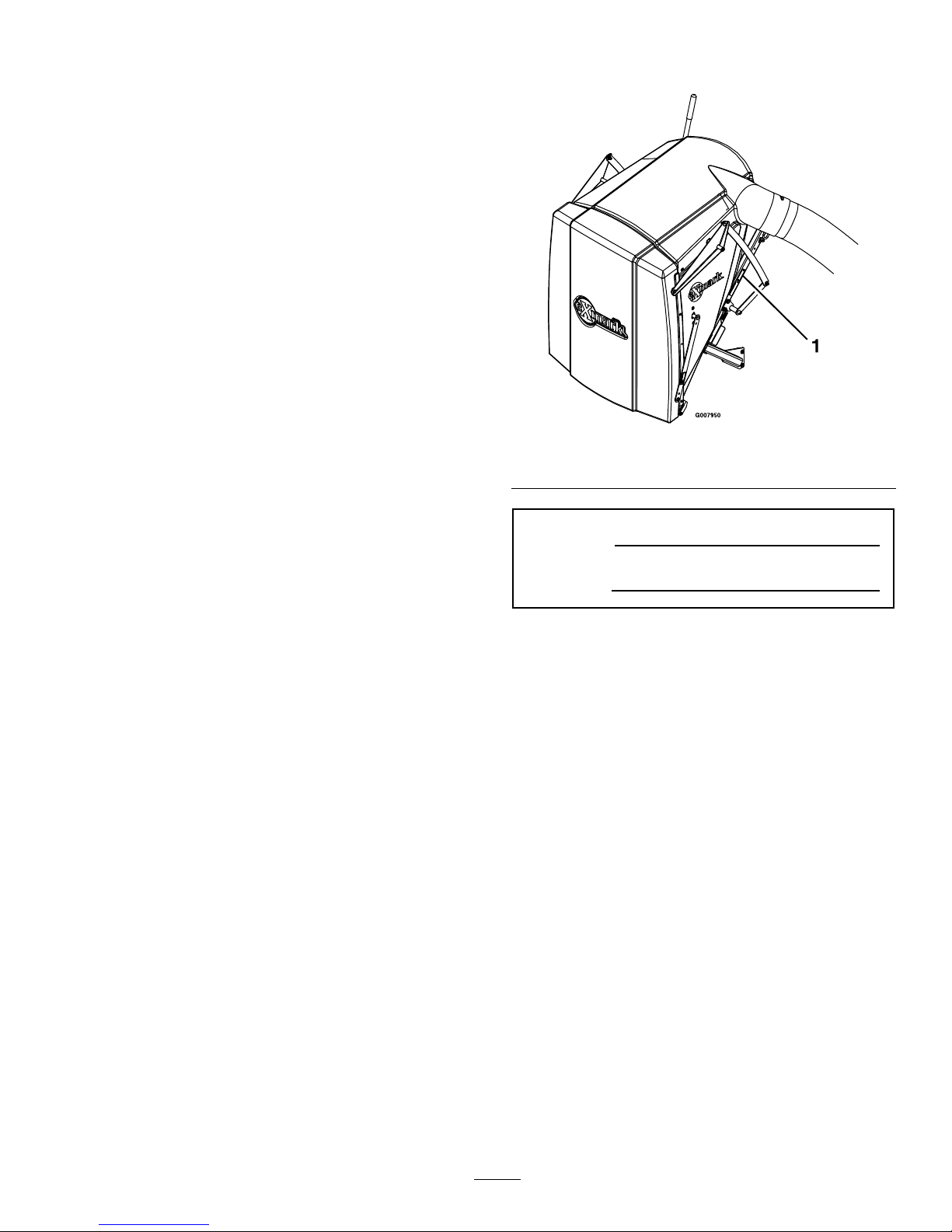
Figure1identiesthelocationofthemodelandserial
numbersontheproduct.Writethenumbersinthe
spaceprovided.
Figure1
1.Modelandserialnumberlocation
ModelNo.
SerialNo.
3
Page 4

Contents
Introduction...........................................................3
Safety.....................................................................5
SafetyAlertSymbol.........................................5
SafeOperatingPractices..................................5
SafetyandInstructionalDecals.......................8
Specications.......................................................10
ModelNumbers............................................10
Systems.........................................................10
Dimensions...................................................10
TorqueRequirements....................................10
ProductOverview................................................11
Operation.............................................................11
Pre-Start........................................................11
OperatingInstructions..................................11
Transporting.................................................14
Maintenance.........................................................16
RecommendedMaintenanceSchedule(s)...........16
PeriodicMaintenance.......................................16
CheckBlowerHousing/Impeller...................16
LubricateGreaseFittings...............................16
CheckConditionofBelt................................17
Adjustments.....................................................18
Cleaning...........................................................19
CleanMuferandRearFrameArea................19
CleanRearScreenInHopper.........................19
CleanBlower.................................................19
Troubleshooting...................................................20
4
Page 5
Safety
Safety
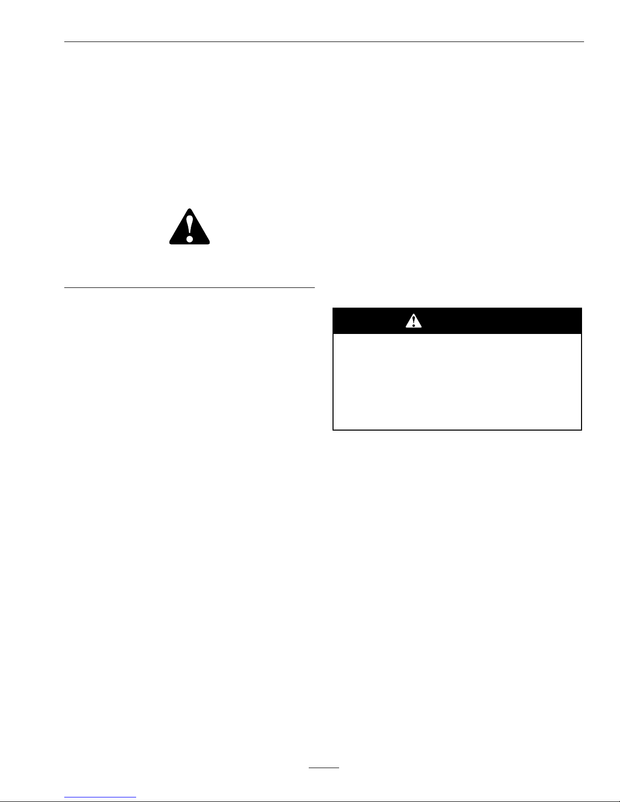
SafetyAlertSymbol
ThisSafetyAlertSymbol(Figure2)isusedbothin
thismanualandonthemachinetoidentifyimportant
safetymessageswhichmustbefollowedtoavoid
accidents
Thissymbolmeans:ATTENTION!BECOME
ALERT!YOURSAFETYISINVOLVED!
Figure2
1.Safetyalertsymbol
Thesafetyalertsymbolappearsaboveinformation
whichalertsyoutounsafeactionsorsituations
andwillbefollowedbythewordDANGER,
WARNING,orCAUTION.
DANGER:Whitelettering/Redbackground.
Indicatesanimminentlyhazardoussituationwhich,if
notavoided,Willresultindeathorseriousinjury.
WARNING:Blacklettering/Orangebackground.
Indicatesapotentiallyhazardoussituationwhich,if
notavoided,Couldresultindeathorseriousinjury.
CAUTION:Blacklettering/Yellowbackground.
Indicatesapotentiallyhazardoussituationwhich,if
notavoided,Mayresultinminorormoderateinjury.
Thismanualusestwootherwordstohighlight
information.Importantcallsattentiontospecial
mechanicalinformationandNoteemphasizes
generalinformationworthyofspecialattention.
SafeOperatingPractices
Training
•ReadthetractorandUltraVacQDSOperator’s
Manualsandothertrainingmaterial.Ifthe
operator(s)ormechanic(s)cannotreadEnglish
itistheowner’sresponsibilitytoexplainthis
materialtothem.
•Becomefamiliarwiththesafeoperationofthe
equipment,operatorcontrols,andsafetysigns.
•Alloperatorsandmechanicsshouldbetrained.
Theownerisresponsiblefortrainingtheusers.
•Neverletchildrenoruntrainedpeopleoperate
orservicetheequipment.Localregulationsmay
restricttheageoftheoperator.
•Theowner/usercanpreventandisresponsible
foraccidentsorinjuriesoccurringtohimselfor
herself,otherpeopleorproperty.
Preparation
•Evaluatetheterraintodeterminewhataccessories
andattachmentsareneededtoproperlyandsafely
performthejob.Onlyuseonmachinesapproved
byExmark.
•Wearappropriateclothingincludingsafetyglasses,
substantialfootwear,longtrousers,andhearing
protection.DoNotoperatewhenbarefootor
whenwearingopensandals.
CAUTION
Thismachineproducessoundlevelsin
excessof85dBAattheoperator’searand
cancausehearinglossthroughextended
periodsofexposure.
Wearhearingprotectionwhenoperatingthis
machine.
•Inspecttheareawheretheequipmentistobe
usedandremoveallrocks,toys,sticks,wires,
bones,andotherforeignobjectswhichcanbe
thrownbythemachineandmaycausepersonal
injurytotheoperatororbystanders.
Operation
•Operateonlyindaylightorgoodarticiallight,
keepingawayfromholesandhiddenhazards.
•Nevermowwiththedischargedeectorraised,
removedoralteredunlessthereisagrass
collectionsystemormulchkitinplaceand
workingproperly.
5
Page 6

Safety
DANGER
Therearerotatingbladesintheblowerand
underthemowerdeck.Bladecontactcan
causeseriousoperatororbystanderinjury
orevendeath.
•DoNotreachintoblowerunlessrotation
indicatorhasstopped.DisengagePTO,
stopengine,removekey ,waitforall
movingpartstostop.engageparking
brake.
•Neveroperatemowerunlessdischarge
deector,entiregrasscollectionsystem,
ormulchkitisinstalled.
•Stopengine,waitforallmovingpartstostop,
removekeyandengageparkingbrake:
–Beforechecking,cleaningorworkingonthe
mower.
–Afterstrikingaforeignobjectorabnormal
vibrationoccurs(inspectthemowerfor
damageandmakerepairsbeforerestarting
andoperatingthemower).
–Beforeclearingblockages.
–Wheneveryouleavethemower.
WARNING
Hands,feet,hair,clothing,oraccessoriescan
becomeentangledinrotatingparts.Contact
withtherotatingpartscancausetraumatic
amputationorseverelacerations.
•DoNotoperatethemachinewithout
guards,shields,andsafetydevicesin
placeandworkingproperly.
•Keephands,feet,hair,jewelry,orclothing
awayfromrotatingparts.
•Stoptheblades,slowdown,andusecautionwhen
crossingsurfacesotherthangrassandwhen
transportingthemowertoandfromtheareato
bemowed.
•Beawareofthemowerdischargepathanddirect
dischargeawayfromothers.
SlopeOperation
WARNING
Usingasingletailwheelmaycontactthe
collectionsystemandcausedifcultsteering
andreducethemachinestability.Thesingle
tailwheeltiremaycontactthebottomofthe
collectionsystemcausingdifcultsteering .
Asingletailwheelwithacollectionsystem
islessstableandapotentialtip-overcould
causeseriousinjuryordeath.
Operatemachineonlywithadualtailwheel
installed.
UseExtremecautionwhenmowingand/orturning
onslopesaslossoftractionand/ortip-overcould
occur.Theoperatorisresponsibleforsafeoperation
onslopes.
DANGER
Operatingonwetgrassorsteepslopescan
causeslidingandlossofcontrol.Wheels
droppingoveredges,ditches,steepbanks,or
watercancauserollovers,whichmayresult
inseriousinjury,deathordrowning.
•DoNotmowslopeswhengrassiswet.
•DoNotmowneardrop-offsornearwater.
•DoNotmowslopesgreaterthan15
degrees.
•Reducespeedanduseextremecaution
onslopes.
•Avoidsuddenturnsorrapidspeed
changes.
•Seeinsidethebackcovertodeterminethe
approximateslopeangleoftheareatobemowed.
•Useawalkbehindmowerand/orahandtrimmer
neardrop-offs,ditches,steepbanksorwater.
(Figure3).
6
Page 7
Safety
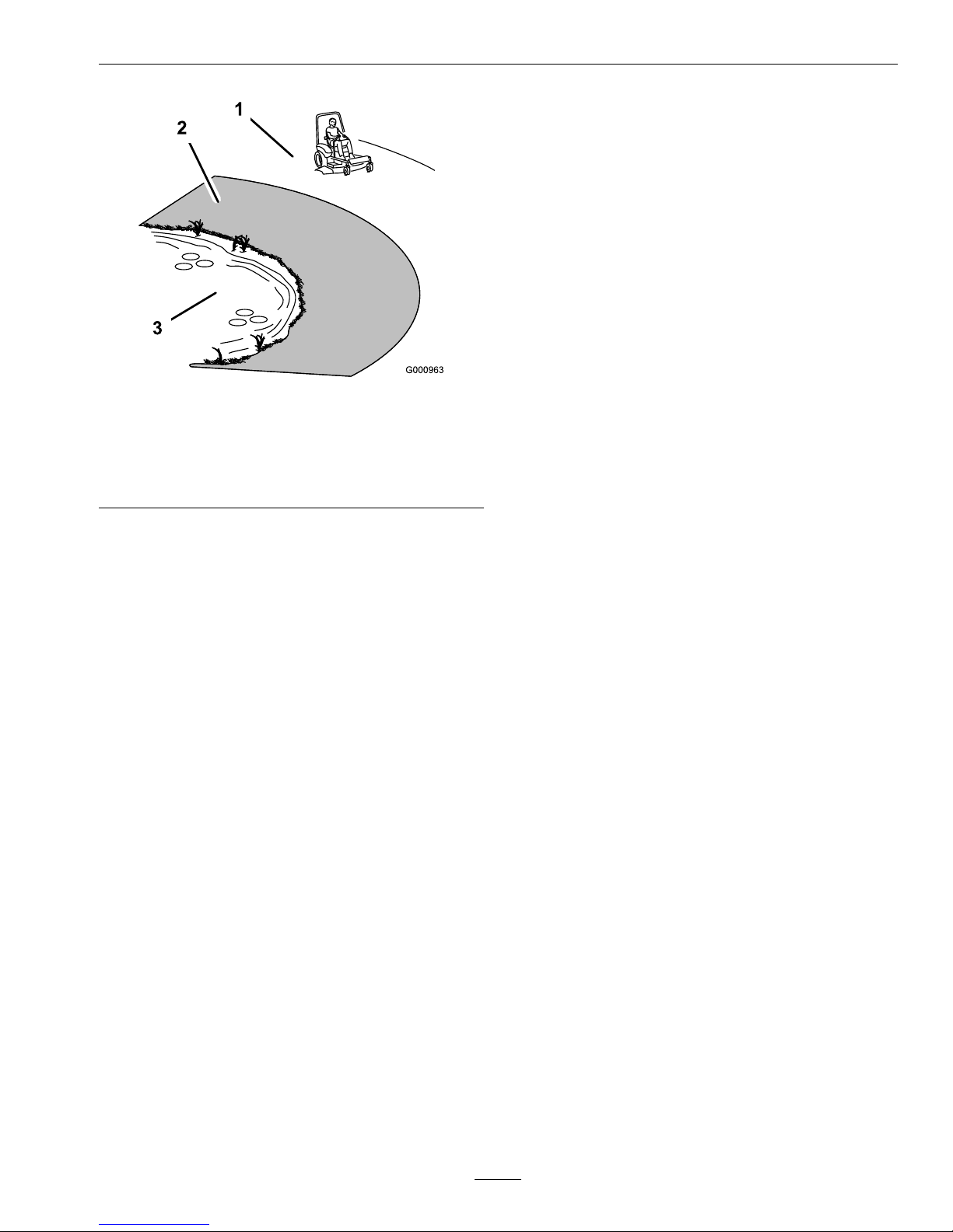
Figure3
1.SafeZone-Usethemowerhereonslopeslessthan15
degrees
2.DangerZone-Useawalkbehindmowerand/orhand
trimmerneardrop-offsandwater.
3.Water
•Removeormarkobstaclessuchasrocks,tree
limbs,etc.fromthemowingarea.Tallgrasscan
hideobstacles.
•Watchforditches,holes,rocks,dipsandrisesthat
changetheoperatingangle,asroughterraincould
overturnthemachine.
•Avoidsuddenstartswhenmowinguphillbecause
themowermaytipbackwards.
•Beawarethatlossoftractionmayoccurgoing
downhill.W eighttransfertothefrontwheels
maycausedrivewheelstoslipandcauselossof
brakingandsteering.
•Alwaysavoidsuddenstartingorstoppingona
slope.Iftireslosetraction,disengagetheblades
andproceedslowlyofftheslope.
•Followthemanufacturer’srecommendationsfor
wheelweightsorcounterweightstoimprove
stability.AlwaysinstallandremovetheUltraVac
QDS,includingcounterweights,asinstructed.
Failuretodosowillcauseareductioninstability
ortraction.DoNotoperatethemowerwithonly
aportionoftheUltraVacQDSinstalled.
•Useextremecarewithgrasscatchersor
attachments.Thesecanchangethestabilityofthe
machineandcauselossofcontrol.Thestability
andtractionofthemachinewillchangeasthe
UltraVacQDShopperllswithgrassclippings.
Useprogressivelygreatercareonslopesasthe
hopperlls.
MaintenanceandStorage
•Disengagedrives,setparkingbrake,stopengine
andremovekeyordisconnectsparkplugwire.
Waitforallmovementtostopbeforeadjusting,
cleaningorrepairing.
•Usecarewhencheckingblades.Wraptheblade(s)
orweargloves,andusecautionwhenservicing
them.Onlyreplaceblades.Neverstraightenor
weldthem.
•Keepallguards,shieldsandallsafetydevicesin
placeandinsafeworkingcondition.
•Checkallboltsfrequentlytomaintainproper
tightness.
•Frequentlycheckforwornordeteriorating
componentsthatcouldcreateahazard.
•Allreplacementpartsmustbethesameas
orequivalenttothepartssuppliedasoriginal
equipment.
7
Page 8
Safety
SafetyandInstructionalDecals
•Keepallsafetysignslegible.Removeallgrease,
dirtanddebrisfromsafetysignsandinstructional
labels.
•Replaceallworn,damaged,ormissingsafety
signs.
•Whenreplacementcomponentsareinstalled,be
surethatcurrentsafetysignsareafxedtothe
replacedcomponents.
•Ifanattachmentoraccessoryhasbeeninstalled,
makesurecurrentsafetysignsarevisible.
•Newsafetysignsmaybeobtainedfrom
yourauthorizedExmarkequipmentdealeror
distributororfromExmarkMfg.Co.Inc.
•Safetysignsmaybeafxedbypeelingoffthe
backingtoexposetheadhesivesurface.Apply
onlytoaclean,drysurface.Smoothtoremove
anyairbubbles.
•Familiarizeyourselfwiththefollowingsafetysigns
andinstructionlabels.Theyarecriticaltothesafe
operationofyourExmarkcommercialmower.
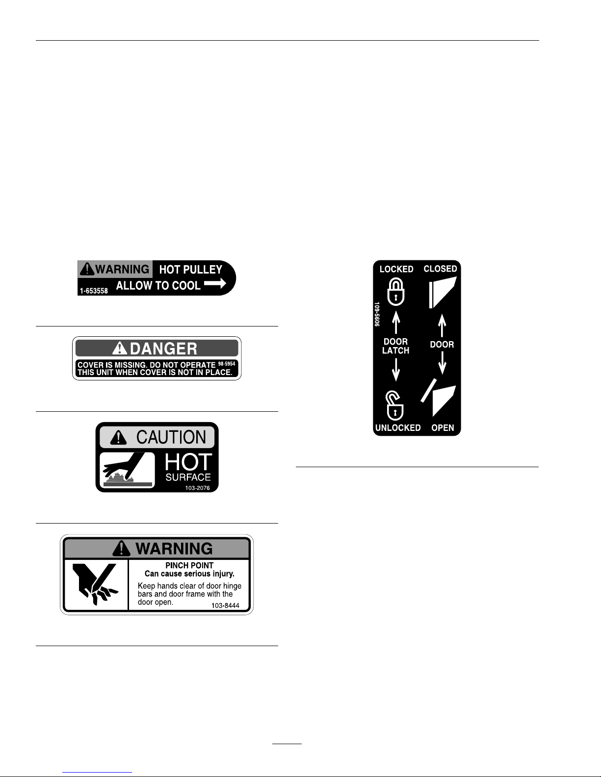
1-653558
98-5954
103-2076
103-8444
109-5606
8
Page 9

Safety
109-5890
9
Page 10

Specications
Specications
ModelNumbers
SerialNos:720,000andHigher
FRUVD–FitsFrontRunnerwith52,60,or72inchdecks
FRCK524–Completingkitfor52inchdeck
FRCK604–Completingkitfor60inchdeck
FRCK724–Completingkitfor72inchdeck
Note:DualtailwheelsareREQUIREDformaximumstability,clearance,andcapacity .
FRDTWK–Completekittoinstalldualtailwheels
FRDTWA–Partialkittoinstalldualtailwheels,re-usessomecomponentsfromsingletailwheel.
Systems
BaggingSystem
•CollectionHopper:
–Commercialgraderotationallymoldedplastic.
–Capacity:12.0bushels
•DumpMechanism:Manualdumpfromseat
•BlowerTube:Flexible,abrasionresistantEPDM
rubberwithpolypropylenehelix.
•Impeller:5–bladed,1/4inch(6.4mm)thick
abrasionresistantsteel,withverticalaxis.
•Impellerbearings:1inch(2.5cm)sealed
non-greaseablebearings.
Dimensions
OverallWidth:
w/UltraV acQDS
52inchDeck66.85inches(169.8cm)
60inchDeck74.44inches(189.1cm)
72inchDeck87.10inches(221.2cm)
OverallLength:
w/UltraV acQDS
52inchDeck118.21inches(300.3cm)
60inchDeck118.32inches(300.5cm)
72inchDeck121.2inches(307.8cm)
CurbWeight:
52inchDeck
264lb(119kg)
60inchDeck
265lb(120kg)
72inchDeck
265lb(120kg)
TorqueRequirements
BoltLocation
Torque
ImpellerSpindleBottom
Nut
32-40ft-lb(43-54N-m)
ImpellerSpindleT opNut75-80ft-lb(102-108N-m)
10
Page 11
Operation
ProductOverview
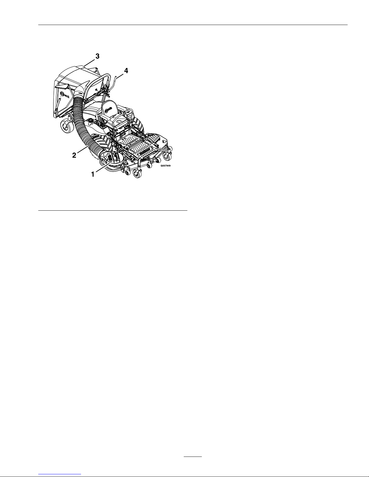
Figure4
1.Blower3.Hopperassembly
2.Flexibletube4.Doorhandle
Operation
Note:Determinetheleftandrightsidesofthe
machinefromthenormaloperatingposition.
Pre-Start
Makesureyouunderstandthecontrols,their
locations,theirfunctions,andtheirsafety
requirements.
Ensuretheblower,beltcover,exibletube,hopper,
anddoorareingoodcondition,properlyattached,
andlatched.
RefertotheMaintenancesectionandperformallthe
necessaryinspectionandmaintenancesteps.
OperatingInstructions
Mowing
1.TheUltraVacQDSbloweroperateswhendeck
driveisengaged.Besurethatallpersonsareclear
ofthemowerdeckbeforeengagingthecutting
blades.Setthethrottleto“midway”position.Pull
outwardonthePTOswitchtothe“ROTATE”
position.Acceleratetofullthrottletobegin
mowing.
2.TodisengagethePTOandblower,setthe
throttleto“midway”position.Pushinonthe
PTOswitchtothe“STOP”positiontostopthe
cuttingbladesandblower.Thecuttingbladeswill
requireaslightlylongeramountoftimetocome
toacompletestopwhentheblowerisinstalled
onthedeck.Verifythatallrotationindicators
havestoppedbeforeclearingblowerassemblyor
mowerdeck
3.Toemptythehopper,rstshutoffdeckdrive.
Liftuponthehandletoopenthedoorandempty
thehopper.Iftheunitistobedrivenontoatruck
ortrailerwiththehopperfull,alwaysbackthe
unituptheramp.Thiswillreducethechanceof
rearwardtipup.SeetheTransportingsection
foradditionalinformationregardingloadinga
unitonatruckortrailer.
4.Closeandlatchthedoorbeforecontinuing
mowing.DoNotengagethecuttingbladeswhile
thedoorisintheopenposition.
Tipsformowingconditions:
11
Page 12

Operation
•Whenmowinginareaswithsandysoil,use
lowliftbladesonthecuttingdeckandhigher
cuttingheightstominimizewearontheblower
components.
•Whenmowinginwetconditions,suchasjustafter
arainorinheavydew ,uselowliftbladesonthe
cuttingdecktominimizepluggingoftheblower.
•Maintainingagroundspeedthatdoesnotpull
downtheengineRPMwillallowforthehighest
productivityandbestqualityofcut.Boggingthe
engineRPMdownbygoingtoofastwillcause
pluggingandqualityofcutissues.
•Whenthehoppergetfull,thesoundoftheblower
willchangeandtherewillbeslightblowoutfrom
thefrontrightcornerofthedeck.Emptyingthe
hopperatthispointwillminimizethepotential
forthetubetoplug.
BaggerRemovalforSideDischarge
1.Shutoffthedeckdrive,stopengineandwaitfor
allmovingpartstostop.Removekey.
2.Removethedischargetubebyreleasingthelock
pinattheblower.Rotateandpullthetubeaway
fromthebloweroutletadapter(seeFigure5).
Figure5
1.Hopperassembly6.Dischargechutepinand
hairpin
2.Lowerhopperlinks7.Belt
3.Alarm8.Blower
4.Decksheave9.Flexibletube
5.Beltcover
3.Removethebeltcoverbylooseningtherearknob
andremovingthefrontknob.Therearknobdoes
notneedtoberemovedcompletelytoremove
thebeltcover.
CAUTION
Thedecksheavewillbecomeveryhot.
Touchingahotdecksheavecancausesevere
burns.
Allowthedecksheavetocoolcompletely
beforeremovingthebelt.
4.Pulltheidlerreleasehandleandremovethebelt
fromtheuppergrooveofthedecksheave.
5.Unlatchthefrontendoftheblower.Pivotthe
blowerbackandliftitoffthedeck.
6.Installthedischargechuteusingthechutepivot
pinandhairpin(seeFigure6).
Figure6
Viewedfromtherightside
1.Hairpin
3.DischargeChute
2.ChutePivotPin
Note:Installchutewiththetabstotherearof
thedecktabsasshown.
WARNING
Anuncovereddischargeopeningwill
allowobjectstobethrowninoperator’sor
bystander’sdirection.Also,contactwith
bladecouldoccur.Thrownobjectsorblade
contactcancauseseriousinjuryorkillyou
orbystanders.
Neveroperatemowerunlessdischarge
deector,orentiregrasscollectionsystem,or
mulchkitisinstalled.
12
Page 13

Operation
7.Re-installtheplasticbeltcoverandtightenthe
knobs.
8.Unplugthewiringforthellsensoratthefront
ofthehopper.Secureloosewireharnessby
routinglooseendpartiallybackdownROPStube.
9.Removethehairpinsandclevispinsholdingthe
hopperassemblytotheROPSweldment.
10.Rotatethehopperassemblyrearwarduntilthe
backofthedoorrestsontheground.Remove
thehairpinsholdingthelowerhopperlinksto
thelowerframemount(Figure7).
11.Thebracketboltedtotherearoftheframeatthe
ROPSremainsontheunit
Note:TheportionsoftheFrontRunnerUltra
Vacthatarenotboltedtothemoweraredesigned
tobeinstalledorremovedintheirentirety.Failure
todosowillcauseareductioninstabilityor
traction.DoNotoperatethemowerwithonlya
portionoftheFrontRunnerUltraVacinstalled.
12.Themachinecannowbeusedforsidedischarge
mowing.
BaggerInstallationforBagging
1.Stopengine,removekey ,andwaitforallmoving
partstostop.
2.Removehairpinandchutepivotpin.Remove
dischargechute.Pivotpinandhairpinmaybe
storedinthepivotholesofthedischargechute
duringbaggingoperation.
3.Laythehopperassemblyonthedoorasshownin
(seeFigure7).
Figure7
1.Secureinthislocation
3.Hopperassembly
2.Lowerlinks
4.Installthehopperassemblyontothemountby
rotatingthelowerhopperlinksforwardand
slippingthemoverthepinsofthelowermount
weldment.Securethelowerlinkstothemount
usingthehairpins.
5.Liftandrotatethehopperassemblyupandalign
theupperpinholeswiththeholesintheROPS
mount.InstalltheupperpinsthroughtheROPS
platesandhopperframetubes.Securetheupper
pinswiththeattachedhairpins.
Figure8
1.Rotatehopperassembly2.Hopperassembly
6.Mountthebloweronthedeckbyslidingthe
mountingpinintothetubeattherearrightcorner
ofthedeck.Swingtheblowerclosed.Adjustthe
positionofthefrontpintoengagetheslotinthe
frontofthedeck.Usethelatchtolocktheblower
inthisposition.Adjustthetensiononthelatch
toholdthebloweruptothedeck,yetallowfor
releasebyhand.
7.Removetheplasticbeltcover.Pullthespring
loadedidlerbackandslipthebeltoverthetop
spindledecksheave.
8.Installtheplasticbeltcover.Therearofthecover
isslottedandcanslipbehindtheplasticknobon
thebeltshieldstud.Theplasticknobdoesnot
needtoberemoved.Thefronthorizontalplastic
knobfortheplasticbeltcovermustbeinstalled
afterthecoverhasbeenpositioned.
Thefrontverticalplasticknobontheoriginal
steelbeltcovercanbeusedforplasticbeltcover.
9.Thehopperinlethasribstoengagethespiral
reinforcementoftheexibletube.Usingamarker
orpaintpen,marktheexibletubeapproximately
4inchesfromtheend.Inserttheendofthe
tubeintothehopperinlet,androtateclockwise
toengage.Rotateandthreadthetubeintothe
hopperinletuptothe4inchmark.Itmaybe
easierto“push”thetubeintotheinletratherthan
rotating(Figure9).
13
Page 14

Operation
Figure9
1.Hopper3.Flexibletube
2.Rotateclockwiseto
engage
10.Slidethelowerendofthetubeassemblyontothe
bloweroutletadapterandrotatetolockinplace.
Installthelockpinthroughthetubeandblower
adapter.
Figure10
1.Lockpin2.Rotatetolock
Note:TheportionsoftheUltraVacthatarenot
boltedtothemoweraredesignedtobeinstalled
orremovedintheirentirety.DoNotoperate
themowerwithonlyaportionoftheUltraVac
installed.
Transporting
TransportingaUnit
Useaheavy-dutytrailerortrucktotransportthe
machine.Lockbrakeandblockwheels.Securely
fastenthemachinetothetrailerortruckwithstraps,
chains,cable,orropes.Besurethatthetrailerortruck
hasallnecessarylightingandmarkingasrequiredby
law .Secureatrailerwithasafetychain.
CAUTION
Thisunitdoesnothaveproperturn
signals,lights,reectivemarkings,ora
slowmovingvehicleemblem.Drivingona
streetorroadwaywithoutsuchequipment
isdangerousandcanleadtoaccidents
causingpersonalinjury.Drivingonastreet
orroadwaywithoutsuchequipmentmayalso
beaviolationofStatelawsandtheoperator
maybesubjecttotrafcticketsand/ornes.
DoNotdriveaunitonapublicstreetor
roadway.
WARNING
Loadingaunitonatrailerortruckincreases
thepossibilityoftip-over.Tip-overcould
causeseriousinjuryordeath.
•Useextremecautionwhenoperatinga
unitonaramp.
•Useonlyasingle,fullwidthramp;Do
Notuseindividualrampsforeachside
oftheunit.
•Ifindividualrampsmustbeused,use
enoughrampstocreateanunbroken
rampsurfacewiderthantheunit.
•DoNotexceeda15°anglebetweenramp
andgroundorbetweenrampandtrailer
ortruck.
•Avoidsuddenaccelerationwhiledriving
unitonaramp.
LoadingaUnit
Iftheunitistobedrivenontoatruckortrailer
withthehopperfull,alwaysbacktheunitupthe
ramp.Thiswillreducethechanceofrearward
tipup.Useextremecautionwhenloadingunits
ontrailersortrucks.Onefullwidthrampthatis
wideenoughtoextendbeyondthereartiresis
recommendedinsteadofindividualrampsforeach
sideoftheunit.Thelowerrearsectionofthetractor
frameextendsbackbetweentherearwheelsand
servesasastopfortippingbackward.Havingafull
widthrampprovidesasurfacefortheframemembers
tocontactiftheunitstartstotipbackward.Ifitis
14
Page 15

Operation
notpossibletouseonefullwidthramp,useenough
individualrampstosimulateafullwidthcontinuous
ramp.
Rampshouldbelongenoughsothattheangles
betweentherampandthegroundandtherampand
thetrailerortruckDoNotexceed15°.Asteeper
anglemaycausemowerdeckcomponentstoget
caughtastheunitmovesfromramptotraileror
truck.Steeperanglesmayalsocausetheunittotip
backward.Ifloadingonornearaslope,position
thetrailerortrucksoitisonthedownsideofthe
slopeandtherampextendsuptheslope.Thiswill
minimizetherampangle.Thetrailerortruckshould
beaslevelaspossible.
Important:DoNotattempttoturntheunit
whileontheramp,youmaylosecontroland
driveofftheside.
Avoidsuddenaccelerationwhendrivinguparamp
andsuddendecelerationwhenbackingdownaramp.
Bothmaneuverscancausetheunittotipbackward.
Dumpcontentsofhopperbeforetransport.DoNot
transporttheunitwiththehopperfull.
15
Page 16

Maintenance
Maintenance
Note:Determinetheleftandrightsidesofthemachinefromthenormaloperatingposition.
WARNING
Whilemaintenanceoradjustmentsarebeing
made,someonecouldstarttheengine.
Accidentalstartingoftheenginecould
seriouslyinjureyouorotherbystanders.
Removethekeyfromtheignitionswitch,
engageparkingbrake,andpullthewire(s)
offthesparkplug(s)beforeyoudoany
maintenance.Alsopushthewire(s)aside
soitdoesnotaccidentallycontactthespark
plug(s).
WARNING
Theenginecanbecomeveryhot.Touching
ahotenginecancausesevereburns.
Allowtheenginetocoolcompletelybefore
serviceormakingrepairsaroundtheengine
area.
RecommendedMaintenanceSchedule(s)
MaintenanceService
Interval
MaintenanceProcedure
Beforeeachuseordaily
•Checktheblowerhousing/impeller.
•Cleanmuferandrearframearea.
•Cleanrearscreeninthehood.
Every25hours
•Lubricategreasettings.
Every50hours
•Checkconditionofbelt.
Yearlyorbeforestorage
•Cleanblower.
PeriodicMaintenance
CheckBlower
Housing/Impeller
ServiceInterval:Beforeeachuseordaily
1.Stopengine,waitforallmovingpartstostop,and
removekey.Engageparkingbrake.
2.Inspectforwearordamagedaily.Replaceor
repairwornpartsasneeded
Note:Whenmowinginareaswithsandysoil,
uselowliftbladesonthecuttingdeckandhigher
cuttingheightstominimizewearontheblower
components.
LubricateGreaseFittings
Note:Seechartforserviceintervals.
1.Stopengine,waitforallmovingpartstostop,and
removekey.Engageparkingbrake.
2.LubricatettingswithNGLIgrade#2
multi-purposegungrease.
Refertothefollowingchartforttinglocations
andlubricationschedule.
LubricationChart
Fitting
Locations
Initial
Pumps
Numberof
Places
Service
Interval
1.Blower
Housing/
Impeller
——
Daily
16
Page 17

Maintenance
LubricationChart
Fitting
Locations
Initial
Pumps
Numberof
Places
Service
Interval
2.Idler
Bushings
1–21
25Hours
3.Belts
——
50Hours
4.Mufer/
RearFrame
——
Daily
5.Hopper
Screen
——
Daily
6.Flexible
Discharge
Tube
——
Daily
7.Fill
Sensor
——
Daily
CheckConditionofBelt
ServiceInterval:Every50hours
1.Stopengine,waitforallmovingpartstostop,and
removekey.Engageparkingbrake.
2.Inspectthebeltfordamageorwear.Replacebelt
withoneofthefollowing:
Deck
PartNo.
52inchDeck
109-4948
60inchDeck
103-0866
72inchDeck
103-0867
3.Inspectthebeltpositionontheidlerarm.
Theidlerarmmaybecomebentduringuseor
transport.Abentidlerarmcouldcausethebelt
tojumpoffoftheidlerandbedamaged.
A.Makesurethebeltcoverisinstalledandrun
theblowerforonetotwominutes.
B.Shutoffthedeckdrive,stopengine,wait
forallmovingpartstostopandremovekey .
Engageparkingbrake.Removethebeltcover
andchecktomakesurethatthebeltisriding
nearthecenteroftheatidlerontheidler
arm.
C.Ifthebeltisnotridingnearthecenterofthe
idler,removetheblower,andbendtheidler
armslightly.
Note:Idlerstillneedstoclearthedeck
stiffenerduringoperation.
D.Reinstalltheblowerandbeltcoverandrepeat
stepsAthroughCuntilthebeltispositioned
nearthecenteroftheidler.
FlexibleDischargeTube
ServiceInterval:Asrequired
Inspecttheexibledischargetubeforwearor
damage.
WARNING
Undernormalusetheexibledischargetube
willwear.Objectscouldexitawornexible
dischargetubeathighspeeds.Thrown
objectscancauseseriousinjuryorkillyou
orbystanders.
Checktheexibledischargetubefortears
andholes.Replacewornexibledischarge
tube.
FillSensor
ServiceInterval:Asrequired
Thellsensorislocatedatthefrontofthehopper,
andiswiredintothePTOcircuit.Whengrasslls
thehopperenoughtoblockoneorbothsensors,
analarmwillsound.Thellsensortestingmustbe
madewiththePTOengaged,buttheenginedoes
nothavetoberunning.
1.Stopengine,waitforallmovingpartstostop,and
removekey.Engageparkingbrake.
2.Unlatchthedoorandpullthedoorhandle
engagementpintoraisethedoortothetopofthe
hopper(seeFigure13).
3.Reachintothehopperandplaceapieceof
maskingorducttapeovertheLHsensor.
4.Closethedoor.
5.SitintheseatandturnthekeytotheRUN
position,butDONOTSTARTtheunit.
6.PulluponthePTOswitchtoengagepowertothe
clutch;youshouldhearaclickfromtheclutch.
7.Thereisasplitseconddelaybeforethellsensor
alarmwillsound.
8.Repeatsteps2through4toremovethetapefrom
thesensor.
17
Page 18
Maintenance
Adjustments
Note:TheUltraVacQDSwasadjustedatthefactorytooperateproperly.However,therearethreebasic
adjustmentsthatcanbemade,shouldyourunitrequirethem:
1.Fillsensors:Locatedinsidethehopper,they
soundanalarmwhenthehopperisfull.Theycan
beadjustedforvaryinggrassconditionsthatll
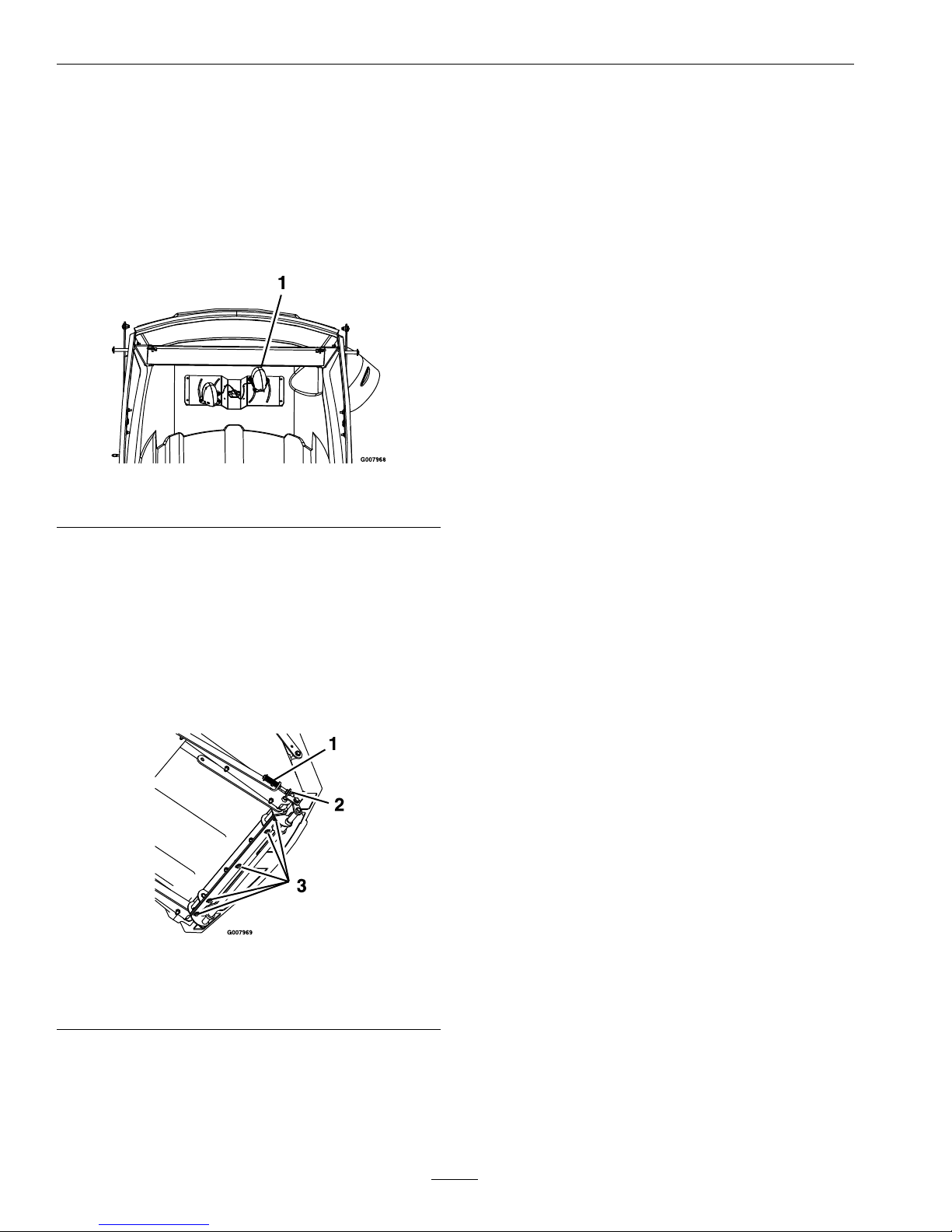
thehopperdifferently(seeFigure11).
Figure11
1.Fillsensor
MovingtheLHsensorupworksbetterinwetter
conditions.
MovingtheLHsensordownworksbetterin
dryerconditions.
2.Latches:Thelatches(Figure12)canbeadjusted.
Withthedoorclosed,thelatchplateshouldbe
setsothatthelatchcamscompletelyengageand
contactthelatchplatesboltedtothedoor.
Figure12
1.Over-centerspring3.Theseveboltsadjust
thelatchcamweldment
2.Whizlocknuts
3.Latchhandlelink:Thelatchhandleneedstobe
abletosnapover-centertokeepthelatchcams
tightagainstthedoorlatchplatesandthedoor
pulledshut.Thelengthofthelatchlinkageis
controlledbythetwowhizlocknutsoneitherside
ofthelatchlink(Figure12).Thewhizlocknuts
shouldbeadjustedsothatreasonableforceon
thehandleisrequiredtoover-centerandlatch
thedoor.DoNotadjustsothattheover-center
springcollapsescompletelywhenthedoorisfully
latched.
18
Page 19

Maintenance
Cleaning
CleanMuferandRear
FrameArea
ServiceInterval:Beforeeachuseordaily
Stopengine,waitforallmovingpartstostop,and
removekey.Engageparkingbrake.
WARNING
Operatingengineparts,especiallythe
mufer,becomeextremelyhot.Severeburns
canoccuroncontactanddebris,suchas
leaves,grass,brush,etc.cancatchre.
•Allowengineparts,especiallythemufer,
tocoolbeforetouching.
•Removeaccumulateddebrisfrommufer
andenginearea.
•Installandmaintaininworkingordera
sparkarresterbeforeusingequipment
onforest-covered,grass-covered,
brush-coveredunimprovedland.
CleanRearScreenInHopper
ServiceInterval:Beforeeachuseordaily
1.Stopengine,waitforallmovingpartstostop,and
removekey.Engageparkingbrake.
2.Openhopperdoorbyremovingpinsasshown
andremoveclippingsthatarestucktoscreenas
showninFigure13.Screencanberemovedby
removingpinsatrearofscreen.
Figure13
1.Putpinhereforstorage3.Screen
2.Pin
CleanBlower
ServiceInterval:Yearlyorbeforestorage
Grassbuildupmaycauseproblemswiththeimpeller
whentheunitisputbackintooperation.
1.Stopengine,waitforallmovingpartstostop,and
removekey.Engageparkingbrake.
2.Removegrassbuildupfromaroundtheimpeller
beforeplacingitinstorage.
19
Page 20

Troubleshooting
Troubleshooting
Important:Itisessentialthatalloperatorsafetymechanismsbeconnectedandinproperoperating
conditionpriortomoweruse.
Whenaproblemoccurs,DoNotoverlookthesimplecauses.Forexample:startingproblemscouldbe
causedbyanemptyfueltank.
Thefollowingtablelistssomeofthecommoncausesoftrouble.DoNotattempttoserviceorreplacemajor
itemsoranyitemsthatcallforspecialtimingoradjustmentprocedures(suchasvalves,governor,etc.).Have
thisworkdonebyyourEngineServiceDealer.
Note:WhendisconnectingelectricalconnectorsDoNotpullonthewirestoseparatetheconnectors.
ProblemPossibleCauseCorrectiveAction
1.Cuttingblade(s)is/arebentorunbalanced.
1.Installnewcuttingblade(s).
2.Blademountingboltisloose.2.Tightentheblademountingbolt.
3.Looseblowerpulleyorpulleyassembly.
3.Tightentheappropriatepulley .
Abnormalvibration.
4.Blowerimpellerbladesarebent.4.ContactanAuthorizedServiceDealer.
Blowerdrivebeltsnapsorbreaksfrequently.
1.Idlerarmisoutofalignment.1.Correctthealignmentoftheidlerarm.
1.Hopperisfull.1.Dumpmorefrequently.
2.Pluggedscreeninbaggerhood.2.Removedebris,leavesorgrassclippings
fromthescreen.
3.Groundspeedistoofast.
3.Drivesloweratfullthrottle.
4.Blowerbeltisworn,loose,orbroken.4.Installnewblowerbelt.
5.Pluggedtubeorblower.5.Locateandremovepluggeddebris.
Excessivegrassblowoutfromthedeck.
6.Conditionsaredry.6.Uselowerliftblade.
1.Hopperistoofull.1.Dumpmorefrequently
2.Groundspeedistoofast.
2.Drivesloweratfullthrottle.
3.Grassistoowet.
3.Cutgrasswhenitisdry.
4.Grassistoolong.4.Cutgrassmorefrequentlyorathighercut
height.
5.Pluggedscreeninbaggerhood.5.Removedebris,leaves,orgrassclippings
fromthescreen.
6.Blowerdrivebeltisworn,loose,or
broken.
6.Installnewbelt.
Blowerandtubesplugtoofrequently.
7.Blowerisplugged.7.Uselowliftbladesinwetconditions.
1.Pluggedblower.1.Removedebris,leaves,orgrassclippings
fromtheblowerimpeller.
Blowerimpellerdoesnotspinfreely.
2.Impellernotaligned.2.ContactanAuthorizedServiceDealer.
Plowingleaves.
1.Deckistoolow.
1.Raisethedeckslightly.
Chasingleaves.
1.Blowoutfromdeck.1.Installananti-blowoutkit–contactan
AuthorizedServiceDealer.
Blowercomponentsshowsignsofwear
and/oraircleanersandcoolingnsaredirty.
1.Sandordryconditions.1.Uselowliftbladesonthecuttingdeckand
highercuttingheights.
20
Page 21

Conditions and Products Covered
Exmark Mfg. Co. Inc. and its affiliate, Exmark Warranty
Company, pursuant to an agreement between them, jointly
warrant on the terms and conditions herein, that we will repair,
replace or adjust any part manufactured by Exmark and found
by us (in the exercise of our reasonable discretion) to be
defective in factory materials or workmanship for a period of
two years.
This warranty applies to Exmark turf equipment purchased on
or after October 1, 2004 sold in the US or Canada. This
warranty may only be assigned or transferred to a second (or
third) owner by an authorized Exmark dealer. The warranty
period commences upon the date of the original retail
purchase.
Products Warranty Period
• All Products (except as noted below) 2 years
• All Attachments and Accessories 1 year
• Metro 21 and Metro 26 Series 1 year
• Belts and Tires 90 days
• Battery 1 Year Prorated
• Engine* Warranty is covered by engine manufacturer
* Please refer to the engine manufacturer’s warranty statement
that is included in the literature packet. We are not authorized
to handle warranty adjustments on engines.
This warranty only includes the cost of parts and labor.
Items and Conditions Not Covered
This warranty does not cover the following:
• Pickup and delivery charges to and from any authorized
Exmark Service Dealer beyond first warrantable service.
• Any damage or deterioration due to normal use, wear and
tear, or exposure.
• Cost of regular maintenance service or parts, such as filters,
fuel, lubricants, tune-up parts, and adjustments.
• Any product or part which has been altered or misused or
required replacement or repair due to normal wear,
accidents, or lack of proper maintenance.
• Any repairs necessary due to use of parts, accessories or
supplies, including gasoline, oil or lubricants, incompatible
with the turf equipment or other than as recommended in
the operator's manual or other operational instructions
provided by Exmark.
There are no other express warranties except for engine and
special emission system coverage stated elsewhere herein or
included with the product.
All warranty work must be performed by an authorized
Exmark Service Dealer using Exmark approved replacement
parts.
Instructions for Obtaining Warranty Service
The product must be registered with original proof of purchase
by an Exmark Service Dealer before obtaining any warranty
service.
Contact any Exmark Service Dealer to arrange service at their
dealership. To locate a dealer convenient to you, access our
website at www.exmark.com. U.S. Customers may also call
402-223-6375.
If for any reason you are dissatisfied with the Service Dealer’s
analysis or with the assistance provided, contact us at:
Exmark Customer Service Department
The Exmark Warranty Company
2101 Ashland Avenue
Beatrice, NE 68310
402-223-6375 or
service@exmark.com
Owner’s Responsibilities
The Exmark turf equipment, including any defective part,
must be returned to an authorized Exmark service dealer
within the warranty period. This warranty extends only to turf
equipment operated under normal conditions. You must read
the operator’s manual. You must also properly service and
maintain your Exmark product as described in the operator’s
manual. Such routine maintenance, whether performed by a
dealer or by you, is at your expense.
General Conditions
The sole liability of Exmark and Exmark Warranty Company
with respect to this warranty shall be repair and replacement
of defective components as set forth herein. Neither Exmark
nor Exmark Warranty Company shall have any liability
for any other cost, loss or damage, including but not
limited to, any incidental or consequential loss or damage.
In particular, we shall have no liability or responsibility for:
• Expenses related to gasoline, oil or lubricants.
• Travel time, overtime, after hours time or other
extraordinary repair charges or charge relating to repairs or
replacements outside of normal business hours at the place
of business of the authorized Exmark Service Dealer.
• Rental of like or similar replacement equipment during the
period of any warranty, repair or replacement work.
• Any telephone or telegram charges or travel charges.
• Loss or damage to person or property other than that
covered by the terms of this warranty.
• Any claims for lost revenue, lost profit or additional cost as
a result of a claim of breach of warranty.
• Attorney's fees.
No Claim of breach of warranty shall be cause for cancellation
or rescission of the contract of sale of any Exmark mower.
Some states do not allow exclusions of incidental or
consequential damages, so the above exclusions and
limitations may not apply to you.
This warranty gives you specific legal rights, and you may
also have other rights which vary from state to state.
2-Year Limited Warranty
Exmark Turf Equipment
(For units purchased on or after October 1, 2004)
G006117
21
Page 22

ServiceRecord
Date:
DescriptionofWorkDone:ServiceDoneBy:
22
Page 23

23
Page 24

MI D-MO UNT RIDI NG ACCESSORIES
SEE EXMARK’S COMPLETE LINE OF ACCESSORIES
WALK-BEHIND ACCESSORIES
GRASS CATCHER
LAZERLOCKER
MICRO-MULCH SYSTEM
TURF STRIPER
STANDON
CUSTOM RIDE SEAT SUSPENSION SYSTEM
DECK LIFT ASSIST KIT
HITCH KIT
LAZERLOCKER
LIGHT KIT
MICRO-MULCH SYSTEM
OPERATOR CONTROLLED DISCHARGE
ROLL OVER PROTECTION SYSTEM (ROPS)
SNOW BLADE
SUN SHADE
TRASH CONTAINER
TURF STRIPER
ULTRA VAC COLLECTION SYSTEM
ULTRA VAC QUICK DISPOSAL SYSTEM
OU T-FRONT RIDING AC CESS ORIE S
CUSTOM RIDE SEAT SUSPENSION SYSTEM
DUAL-TAIL WHEEL
FLOOR PAN EXTENDER
HITCH KIT
LIGHT KIT
MICRO-MULCH SYSTEM
ROLL OVER PROTECTION SYSTEM (ROPS)
ROTARY BROOM
SNOW BLADE
SNOWBLOWER
SUN SHADE
TRASH CONTAINER
ULTRA VAC COLLECTION SYSTEM
ULTRA VAC QUICK DISPOSAL SYSTEM
WEATHER CAB
PlaceModelNo.andSerialNo.
LabelHere(IncludedintheLiterature
Pack)orFillinBelow
DatePurchased
ModelNo.
SerialNo.
©2006–2008ExmarkMfg.Co.,Inc.
IndustrialParkBox808
Beatrice,NE68310
AllRightsReserved
PartNo.4500-274Rev.A
(402)223-6300
Fax(402)223-5489
PrintedintheUSA.
www.exmark.com
 Loading...