

Page 1

FR524/FR604/
FR724
ForSerialNos.
720,000&Higher
PartNo.4500-230Rev.A
Page 2

Exmarkreservestherighttomakechangesor
addimprovementstoitsproductsatanytime
withoutincurringanyobligationtomakesuch
changestoproductsmanufacturedpreviously.
Exmark,oritsdistributorsanddealers,accept
noresponsibilityforvariationswhichmaybe
evidentintheactualspecicationsofitsproducts
andthestatementsanddescriptionscontained
inthispublication.
©2005–2008—ExmarkMfg.Co.,Inc.
IndustrialParkBox808
Beatrice,NE68310
Contactusatwww.Exmark.com.
2
PrintedintheUSA.
AllRightsReserved
Page 3

Introduction
CONGRATULATIONSonthepurchaseofyour
ExmarkCuttingDeck.Thisproducthasbeen
carefullydesignedandmanufacturedtogiveyou
amaximumamountofdependabilityandyearsof
trouble-freeoperation.
Thismanualcontainsoperating,maintenance,
adjustment,andsafetyinstructionsforyourExmark
mower.
BEFOREOPERATINGYOURMOWER,
CAREFULLYREADTHISMANUALINITS
ENTIRETY.
Byfollowingtheoperating,maintenance,andsafety
instructions,youwillprolongthelifeofyourmower,
maintainitsmaximumefciency,andpromotesafe
operation.
Ifadditionalinformationisneeded,orshouldyou
requiretrainedmechanicservice,contactyour
authorizedExmarkequipmentdealerordistributor.
Figure1
1.Modelandserialnumberlocation
ModelNo.
SerialNo.
AllExmarkequipmentdealersanddistributorsare
keptinformedofthelatestmethodsofservicing
andareequippedtoprovidepromptandefcient
serviceintheeldorattheirservicestations.They
carryamplestockofservicepartsorcansecurethem
promptlyforyoufromthefactory.
AllExmarkpartsarethoroughlytestedandinspected
beforeleavingthefactory,however,attentionis
requiredonyourpartifyouaretoobtainthefullest
measureofsatisfactionandperformance.
Wheneveryouneedservice,genuineExmarkparts,
oradditionalinformation,contactanAuthorized
ServiceDealerorExmarkCustomerServiceandhave
themodelandserialnumbersofyourproductready .
Figure1identiesthelocationofthemodelandserial
numbersontheproduct.Writethenumbersinthe
spaceprovided.
3
Page 4

Contents
Introduction...........................................................3
Safety.....................................................................5
SafetyAlertSymbol.........................................5
SafeOperatingPractices..................................5
SafetyandInstructionalDecals.......................7
Specications.........................................................9
ModelNumbers..............................................9
Systems...........................................................9
Dimensions.....................................................9
TorqueRequirements....................................10
Setup....................................................................11
AssembleDecktoFrontRunner.....................11
DeckRemoval...............................................13
ProductOverview................................................14
Operation.............................................................14
DeckRaisingandLowering...........................14
Maintenance.........................................................17
RecommendedMaintenanceSchedule(s)...........17
PeriodicMaintenance.......................................17
CheckMowerBlades.....................................17
CheckforLooseHardware............................18
CheckTirePressures.....................................18
ChangeGearboxOil......................................18
LubricateGreaseFittings...............................19
ThreadLockingAdhesives.............................19
Adjustments.....................................................20
DeckLeveling...............................................20
CasterPivotBearingsPre-load
Adjustment...............................................20
Cleaning...........................................................21
CleanGrassBuild-UpUnderDeck................21
Troubleshooting...................................................22
4
Page 5
Safety
Safety
SafetyAlertSymbol
ThisSafetyAlertSymbol(Figure2)isusedbothin
thismanualandonthemachinetoidentifyimportant
safetymessageswhichmustbefollowedtoavoid
accidents
Thissymbolmeans:ATTENTION!BECOME
ALERT!YOURSAFETYISINVOLVED!
Figure2
1.Safetyalertsymbol
Thesafetyalertsymbolappearsaboveinformation
whichalertsyoutounsafeactionsorsituations
andwillbefollowedbythewordDANGER,
WARNING,orCAUTION.
DANGER:Whitelettering/Redbackground.
Indicatesanimminentlyhazardoussituationwhich,if
notavoided,Willresultindeathorseriousinjury.
WARNING:Blacklettering/Orangebackground.
Indicatesapotentiallyhazardoussituationwhich,if
notavoided,Couldresultindeathorseriousinjury.
CAUTION:Blacklettering/Yellowbackground.
Indicatesapotentiallyhazardoussituationwhich,if
notavoided,Mayresultinminorormoderateinjury.
•Neverletchildrenoruntrainedpeopleoperate
orservicetheequipment.Localregulationsmay
restricttheageoftheoperator.
•Theowner/usercanpreventandisresponsible
foraccidentsorinjuriesoccurringtohimselfor
herself,otherpeopleorproperty.
Preparation
•DoNotmodifytheFrontRunnercuttingdeck.
•OnlyuseonmachinesapprovedbyExmark.
•Wearappropriateclothingincludingsafetyglasses,
substantialfootwear,longtrousers,andhearing
protection.DoNotoperatewhenbarefootor
whenwearingopensandals.
CAUTION
Thismachineproducessoundlevelsin
excessof85dBAattheoperator’searand
cancausehearinglossthroughextended
periodsofexposure.
Wearhearingprotectionwhenoperatingthis
machine.
•Inspecttheareawheretheequipmentistobe
usedandremoveallrocks,toys,sticks,wires,
bones,andotherforeignobjectswhichcanbe
thrownbythemachineandmaycausepersonal
injurytotheoperatororbystanders.
Thismanualusestwootherwordstohighlight
information.Importantcallsattentiontospecial
mechanicalinformationandNoteemphasizes
generalinformationworthyofspecialattention.
SafeOperatingPractices
Training
•ReadthetractorandcuttingdeckOperator’s
Manualsandothertrainingmaterial.Ifthe
operator(s)ormechanic(s)cannotreadEnglish
itistheowner’sresponsibilitytoexplainthis
materialtothem.
•Becomefamiliarwiththesafeoperationofthe
equipment,operatorcontrols,andsafetysigns.
•Alloperatorsandmechanicsshouldbetrained.
Theownerisresponsiblefortrainingtheusers.
Operation
•Operateonlyindaylightorgoodarticiallight,
keepingawayfromholesandhiddenhazards.
•Neverfoldthedeckwithbladesrunning.
•Stopengine,waitforallmovingpartstostop,
removekeyandengageparkingbrake:
–Beforechecking,cleaningorworkingonthe
mower.
–Afterstrikingaforeignobjectorabnormal
vibrationoccurs(inspectthemowerfor
damageandmakerepairsbeforerestarting
andoperatingthemower).
–Beforeclearingblockages.
–Wheneveryouleavethemower.
5
Page 6

Safety
WARNING
Hands,feet,hair,clothing,oraccessoriescan
becomeentangledinrotatingparts.Contact
withtherotatingpartscancausetraumatic
amputationorseverelacerations.
•DoNotoperatethemachinewithout
guards,shields,andsafetydevicesin
placeandworkingproperly.
•Keephands,feet,hair,jewelry,orclothing
awayfromrotatingparts.
•Stoptheblades,slowdown,andusecautionwhen
crossingsurfacesotherthangrassandwhen
transportingthemowertoandfromtheareato
bemowed.
•Bealert,slowdownandusecautionwhenmaking
turns.Lookbehindandtothesidebefore
changingdirections.
MaintenanceandStorage
•DisengagePTO ,setparkingbrake,stopengine
andremovekeyordisconnectsparkplugwire.
Waitforallmovementtostopbeforeadjusting,
cleaningorrepairing.
•Usecarewhencheckingblades.Wraptheblade(s)
orweargloves,andusecautionwhenservicing
them.Onlyreplaceblades.Neverstraightenor
weldthem.
•Keepallguards,shieldsandallsafetydevicesin
placeandinsafeworkingcondition.
•Checkallboltsfrequentlytomaintainproper
tightness.
•Frequentlycheckforwornordeteriorating
componentsthatcouldcreateahazard.
•Allreplacementpartsmustbethesameas
orequivalenttothepartssuppliedasoriginal
equipment.
6
Page 7
SafetyandInstructionalDecals
•Keepallsafetysignslegible.Removeallgrease,
dirtanddebrisfromsafetysignsandinstructional
labels.
•Replaceallworn,damaged,ormissingsafety
signs.
•Whenreplacementcomponentsareinstalled,be
surethatcurrentsafetysignsareafxedtothe
replacedcomponents.
•Ifanattachmentoraccessoryhasbeeninstalled,
makesurecurrentsafetysignsarevisible.
Safety
•Newsafetysignsmaybeobtainedfrom
yourauthorizedExmarkequipmentdealeror
distributororfromExmarkMfg.Co.Inc.
•Safetysignsmaybeafxedbypeelingoffthe
backingtoexposetheadhesivesurface.Apply
onlytoaclean,drysurface.Smoothtoremove
anyairbubbles.
•Familiarizeyourselfwiththefollowingsafetysigns
andinstructionlabels.Theyarecriticaltothesafe
operationofyourExmarkcommercialmower.
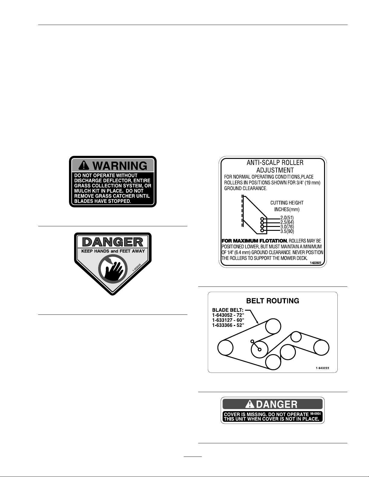
1-303508
1-633922
1-403005
1-643222
98–5954
7
Page 8
Safety
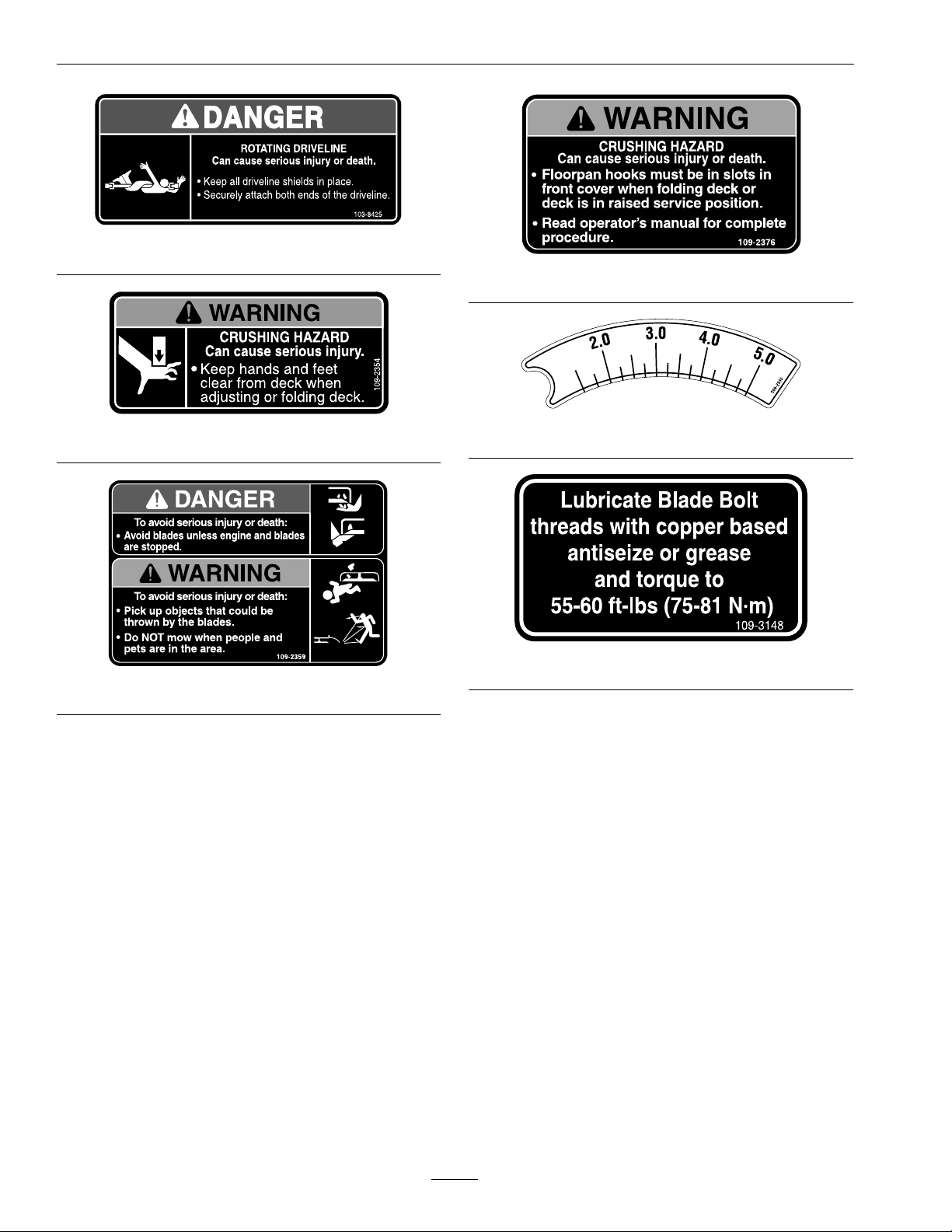
103-8425
109-2376
109-2354
109-2359
109-2993
109-3148
8
Page 9

Specications
ModelNumbers
SerialNos:720,000andHigher
FR524;FR604;FR724
Specications
Systems
Tires&Wheels
FrontCaster
Type
Quantity
Tread
Size9x3.50–4
CuttingDeck
•ModelNumbers:
–FR524
–FR604
–FR724
•CuttingWidth:
–52inchDeck:52inch(132cm)
–60inchDeck:60inch(152cm)
–72inchDeck:72inch(183cm)
•Discharge:Side
•BladeSize:(3ea.)
–52inchDeck:18.00inches(45.7cm)
Semi-Pneumatic
2
Smooth
•Deck:
Fulloatingdeckisattachedtoout-frontsupport
frame.Sixanti-scalprollersprovidemaximum
turfprotection.Deckdesignallowsforbagging,
mulching,orsidedischarge.
•DeckDepth:
–52inchDeck:51/2inches(14cm)
–60inchDeck:51/2inches(14cm)
–72inchDeck:51/2inches(14cm)
•CuttingHeightAdjustment:
Adjustsfrom1inch(2.5cm)to5inches(12.7cm)
innitelyvariable
•MulchingKit:Optional
Dimensions
OverallWidth:
52inch
Deck
Deector
Down
Deector
Up
64.6inches
(164.1cm)
53.9inches
(136.9cm)
60inch
Deck
72.7inches
(184.7cm)
61.4inches
(156.0cm)
72inch
Deck
84.4inches
(214.4cm)
73.3inches
(186.2cm)
–60inchDeck:20.50inches(52.1cm)
–72inchDeck:24.50inches(62.2cm)
•DeckDrive:
–Shaftdrivetogearboxatrearofdeck.
–Beltdrivefromgearboxtobladespindles.
OverallLength:
52inchDeck60inchDeck72inchDeck
42.5inches
(108.0cm)
42.3inches
(107.4cm)
OverallHeight:
52inchDeck60inchDeck72inchDeck
18.0inches
(45.7cm)
9
18.0inches
(45.7cm)
45.5inches
(115.6cm)
18.0inches
(45.7cm)
Page 10

Specications
CurbWeight:
52inchDeck60inchDeck72inchDeck
393lb(178kg)434lb(197kg)514lb(233kg)
TorqueRequirements
BoltLocation
BladeMountingBolt
(lubricatewithanti-seize)
GearboxMountingBolts16-18ft-lb(22-24N-m)
DriveShaftSetScrew
DriveShaftPinchBolt
CutterHousingSpindle
Nut
Anti-ScalpRollerNyloc
NutSeeFigure12
Anti-ScalpRollerWhizlock
NutSeeFigure12
Torque
55-60ft-lb(75-81N-m)
18ft-lb(24N-m)
44ft-lb(60N-m)
140-145ft-lb
(190-197N-m)
30-35ft-lb(41-47N-m)
30-35ft-lb(41-47N-m)
10
Page 11

Setup
WARNING
OperatingaFrontRunnertractorwithoutan
approvedExmarkfrontmountattachment
increasesthepossibilityofforwardtipover.
Tip-overcouldcauseseriousinjuryordeath.
WhenoperatingaFrontRunnertractor
withoutanapprovedExmarkfrontmount
attachment,observethefollowing:
•Limitoperationtominimumrequiredto
installadifferentfrontmountattachment.
Setup
•Minimizespeedanduseextremecaution.
•Onlyoperateonaatlevelsurface.
•DoNotoperateupordownatrailerramp.
•Avoidsuddenaccelerationordeceleration.
AssembleDeckto
FrontRunner
Important:DoNottransportFrontrunner
tractorwithoutandapprovedExmarkfront
mountattachment.
1.Stoptheengine,waitforallmovingpartstostop,
engagetheparkingbrake,andremovethekey.
2.Rotatethefoldlocklever,locatedonthedeck,in
theunlockedposition(Figure3).
Figure3
1.Foldlocklevershownintheunlockedposition
3.Onthetractor,removethetworetainingpins
onhitchlatchessothelatchescanactuatefreely.
Raisetheoorpanandlockinuprightposition
(Figure4).
Figure4
1.Removetheretainingpinsfrombothhitchlatches
2.Floorpanshownlockedintheuprightposition
4.Alignthefrontframeofthemowerdecktothe
Frontrunnertractorhitch.
5.Manuallyliftuponthehitchtogetthebarsonthe
frontframestartedintothereceiversofthehitch.
6.Pushthefrontframetowardsthetractoruntilthe
twohitchlatchesseatintothe“secure”position.
11
Page 12

Setup
7.Insertthehitchlatchretainingpinsintothehitch
pinlock.Thedeckisnowlockedontothetractor.
8.Reinstallthekeyandturntheswitchtothe“run”
position.DoNotstarttheengine.
9.Alignthecylinderrodendtothetopholeofthe
oatlinkbracketandinsertthepinasshownin
Figure5.Insertthecotterhairpintolockthe
cylinderpinintoplace.
1.Retainingpin
2.Cotterhairpin
Figure6
3.Weighttransferchains
Figure5
1.Floatlinkbracket
2.Cylinderpin
3.Cylinder
4.Besuregreasezerkis
pointedupward
WARNING
Incorrectlyraisingorloweringamowerdeck
canbedangerous.Adroppedmowerdeck
canresultinaseriousinjuryorproperty
damage.
•Alwaysraiseandlowerdeckonat,dry
ground,freeofanyobstructions.
•Alwaysmakesurethedeckissecurely
latchedinthe“up”or“down”position.
10.Retractthecylindertofoldthedeckupward.
Attachtheweighttransferchains.Itisvery
importantnottotwistthechains.Lockthe
chainsontothepinbyinsertingthecotterhairpin
(Figure6).
WARNING
Operatingthemowerdeckintheraised
servicepositioncanbedangerous.Engaging
thePTOwithadeckintheraisedposition
canresultinaseriousinjuryorproperty
damage.
Alwayslowerandlockmowerdeckinthe
operationpositionbeforeengagingthePTO.
11.Extendthecylinderfullyuntilthecasterwheels
contactthegroundandthedeckisinthefully
raisedposition.Thefoldlockleversshouldhave
resetandsnappedintothe“locked”position.
Lowertheoorpan.
Figure7
1.Floorpan
12
2.Rotatefoldlockleverto
uprightposition.
Page 13

Setup
WARNING
Operatingmowerwithoutfoldlocklevers
securelylatchedcanresultinthemower
deckfoldingupunexpectedlyandcancause
seriousinjury.
Alwaysoperatemowerwiththefoldlock
leverssecurelylatched.
12.Connectthedriveshaftbypushingbackthe
springloadedcollar.Alignandcouplethedrive
shafttothesplineddriveshaftandreleasethe
collar(Figure8).
5.Retractthecylinderandpartiallyfoldthedeck
justtothepointwheretheweighttransferchains
goslack.
6.Pulloutthehairpinsandchainpinsfromthe
clevisbracket.Placethepinandcotterhairpinon
thechainandsetaside.
7.Lowerthedeckbyextendingthecylinderuntilthe
deckfoldsdown.Thecastertiresshouldtouch
theground.
8.Theoatlinkbracketswillstarttorotateforward
andatthispoint,thecylindercanbedetachedat
therodendbypullingthepinoutofthebracket.
Liftthecylinderoutofthewayandpositionthe
rodendsothatitrestsonthebuckleoftheheight
indicatorbracket.
9.Removethehitchlatchpinsfromthehitch
brackets.Raisethehitchlatchabovetheholeand
insertpin.Thetopofthehitchlatchshouldrest
underthepin(seeFigure9).
Figure8
Viewedfrombelowthemachine
1.Pushspringloadedcollartowardsdeck
DeckRemoval
1.Stopengine,waitforallmovingpartstostop,and
removekey.Engageparkingbrake.
2.Disconnectthedriveshaftbypullingbackonthe
springloadedcollarandpullingawayfromthe
splinedshaft(seeFigure8).Laythedriveshaft
ontheground.
3.Insertkeyandturntothe“run”position.Do
Notstarttheengine.
4.Extendthecylinderuntilthefoldlocklatches
areunloaded,andthenrotatethemtowardthe
tractor.
Figure9
1.Floorpanlockedin
uprightposition
2.Hitchlatchpins
3.Hitchlatchesin“up”
position
10.Standinfrontofthedeckandpulltheunitaway
fromthetractororbackthetractorawayfrom
thedeck.
Important:DoNottransportFrontRunner
tractorwithoutanapprovedExmarkfrontmount
attachment.
13
Page 14

Operation
ProductOverview
1.Foldlocklever
2.Anti-scalprollers
Figure10
3.Casterwheel
Operation
DeckRaisingandLowering
SettingtheCuttingHeight
Thecuttingheightofthemowerdeckisadjusted
from1to5inches(2.5cmto12.7cm)innitely
variable.
1.Thekeymustbeinthe“run”positiontosetthe
cutheight.
2.Extendorretractcylinderuntilthecuttingheight
indicatorpointstothedesiredcutheight.
AdjustingtheAnti-ScalpRollers
Itisrecommendedtochangetheanti-scalproller
position,whentheheightofcuthaschanged.
1.Stopthemachineandmovethemotioncontrol
leversoutwardtotheneutrallockedposition.
2.DisengagethePTO.
3.Engagetheparkbrake.
4.Stoptheengine,removethekeyandwaitforall
movingpartstostop.
5.Afteradjustingtheheightofcut,adjustthe
anti-scalprollersbyremovingthewhizlocknut
andthespringdiscwasher.
6.Placetherollersinoneofthepositionsshown
(Figure11).Rollerswillmaintain3/4inch(19
mm)clearancetothegroundtominimizegouging
androllerwearordamage.
Figure11
Forcuttingheightsabove3.5inches(90mm)usethe
bottomhole.Therollerswillstillbeeffectiveagainst
scalping.
14
1.Anti-scalproller
mountingbracket
2.Cuttingheight
Page 15

Operation
ForMaximumDeckFlotation,placetherollers
oneholepositionlower.Rollersshouldmaintain
1/4inch(6.4mm)clearancetotheground.Do
Notadjusttherollerstosupportthedeck.
7.Besurethewhizlocknutsareinstalledwiththe
springdiscwasherbetweentheangeofthenut
andthemountingbracket(seeFigure12).
8.Torquethe3/8-16whizlocknutto30-35ft-lb
(41-47N-m)(Figure12).
9.Ifthe3/8nylocnuthasbeenremoved,re-install
andtorqueitto30–35ft-lb(41-47N-m)
(Figure12).
2.Fullyextendthecylindertounloadthefoldlock
levers.
3.Rotatethefoldlocklevers,locatedoneachside
ofthedeck,totheunlockedposition(Figure3).
4.Retractthecylinderandthedeckwillfoldto
approximately50degrees.
WARNING
Operatingthemowerdeckintheraised
servicepositioncanbedangerous.Engaging
thePTOwithadeckintheraisedposition
canresultinaseriousinjuryorproperty
damage.
Alwayslowerandlockmowerdeckinthe
operationpositionbeforeengagingthePTO.
RaisingtheMowerDeckintothe
StoragePosition
Figure12
1.Springdiscwasher
(conetowardsnut)
2.Frontrightanti-scalp
bracketshown
3.3/8nyloc-torqueto30-35
ft-lb(41-47N-m)
4.3/8-16whizlocknut
torqueto30-35ft-lb
(41-47N-m)
RaisingtheMowerDeckintoService
Position
1.Stopengine,waitforallmovingpartstostop,
engageparkingbrake,andturnkeyto“run”
position.DoNotstarttheengine.
WARNING
Incorrectlyraisingorloweringamowerdeck
canbedangerous.Adroppedmowerdeck
canresultinaseriousinjuryorproperty
damage.
1.Stopengine,waitforallmovingpartstostop,
engageparkingbrake,andturnkeyto“run”
position.DoNotstarttheengine.
2.Flipuptheoorpanandremovefullfoldpin.
Retractthecylindertoalignholesinoatlink
bracketwithholesinfrontframe.(Deckwillbe
atornearlowestheight.)Insertintothebottom
holeoftheoatlinkbracket(seeFigure13).
Lowertheoorpan.
•Alwaysraiseandlowerdeckonat,dry
ground,freeofanyobstructions.
•Alwaysmakesurethedeckissecurely
latchedinthe“up”or“down”position.
15
Page 16

Operation
4.Ifthefullfoldpinwasusedwhenthedeckwas
folded,removeitfromtheoatlinkandplaceit
inthestoragelocationundertheoorpan.
5.Fullyextendthecylinderuntilitstops.Conrm
thatthelatchesareinthelockedposition.
6.Retractthecylinderuntilthedecklowerstothe
desiredcutheightreadingshownontheheight
indicatorbar.
WARNING
Figure13
1.Removethehairpinand
fullfoldpin
2.Floatlinkbrackets
3.Insertpinhere
4.Hairpin
5.Fullfoldpin
WARNING
Foldingthemowerdeckwiththeoorpanin
lockedpositionmaybedangerous.Hooks
willnotautomaticallydropintheslotsonthe
frontcover.
Makesuretheoorpanisnotlockedinthe
uprightposition.
3.Fullyretractcylinder.Thedeckwillfoldtoan
approximate70degreeangle.
WARNING
Drivingthemowerdeckinthefoldedservice
positioncanbedangerous.Themowercan
tipforward.
Operatingmowerwithoutlockinglatches
securelylatchedcanresultinthemowerdeck
foldingupunexpectedly.Themowerdeck
foldingupunexpectedlycancauseserious
injury.
Alwaysoperatemowerwithlockinglatches
securelylatched.
Alwayslowerandlockmowerdeckinthe
operationpositionbeforedriving.
LoweringtheMowerDecktothe
OperatingPosition
1.Makecertainthatyouandanyobserversareclear
ofthedeck.
2.Raisetheoorpantothelockedpositionas
showninFigure13.
3.Extendthecylinderuntilthefrontcasterwheels
justtouchtheground.
16
Page 17

Maintenance
Note:Determinetheleftandrightsidesofthemachinefromthenormaloperatingposition.
WARNING
Whilemaintenanceoradjustmentsarebeing
made,someonecouldstarttheengine.
Accidentalstartingoftheenginecould
seriouslyinjureyouorotherbystanders.
Removethekeyfromtheignitionswitch,
engageparkingbrake,andpullthewire(s)
offthesparkplug(s)beforeyoudoany
maintenance.Alsopushthewire(s)aside
soitdoesnotaccidentallycontactthespark
plug(s).
Maintenance
RecommendedMaintenanceSchedule(s)
MaintenanceService
Interval
Aftertherst50hours
Beforeeachuseordaily
Every40hours
Every100hours
Yearly
MaintenanceProcedure
•Changeoilinallthreegearboxhousings.Addoilasneededuntillevelwithoildrainplug.
•Checkthemowerblades.
•Checkforloosehardware.
•Greasethefrontcasterwheelhub.
•Cleanthegrassbuild-upfromunderthedeck.
•Checktheconditionofthebelts.
•Greasethedriveshaft.
•Greasetheheightadjustmentshaftbearings.
•Changeoilinallthreegearboxhousings.Addoilasneededuntillevelwithoildrainplug.
•Greasethedeckip-up.
•Greasethefrontcasterpivots.
•Greasethedeckdrivebeltidlerarm.
PeriodicMaintenance
CheckMowerBlades
ServiceInterval:Beforeeachuseordaily
1.Stopengine,waitforallmovingpartstostop,and
removekey.Engageparkingbrake.
2.Inspectbladesandsharpenorreplaceasrequired.
3.Reinstalltheblades(iftheywereremoved)inthe
followingorder:
A.Installbushingthroughbladewithbushing
angeonbottom(grass)sideofblade.
Figure14
1.Installbushinginbladepriortoinstallingbushingin
spindle.
17
Page 18

Maintenance
B.Installbushing/bladeassemblyintospindle.
Figure15
1.Usewrenchherefor
bladeinstallation.This
nuthasbeentorquedto
90–110ft-lb(122–149
N-m)
2.Torqueto55-60ft-lb
(75-81N-m)Apply
lubricanttothreads
asneededtoprevent
seizing.Copper-based
anti-seizepreferable.
Greaseacceptable
substitute.
C.Applylubricanttothreadsofbladeboltas
neededtopreventseizing.Copper-based
anti-seizepreferable.Greaseacceptable
substitute.Installbladeboltngertight.Place
wrenchonthetopspindlenutthentorquethe
bladeboltsto55-60ft-lb(75-81N-m).
CheckTirePressures
ServiceInterval:Every40hours
Thefrontcastertiresaresemi-pneumaticandDo
Notneedtobeinated.
ChangeGearboxOil
ServiceInterval:Aftertherst50hours
Every100hoursthereafter
1.Stopengine,waitforallmovingpartstostop,and
removekey.Engageparkingbrake.
2.Placeunitonalevelsurface.
3.Removethegearboxanddriveshaftassembly
fromthemowerdeck.Retainhardwareforre-use.
4.Removetheoildrainplugonthesideofthe
gearboxsectionanddrainoil(Figure16).
WARNING
Incorrectinstallationofthebladeor
componentsusedtoretainthebladecan
bedangerous.Failuretousealloriginal
componentsandassembledasshowncould
allowabladeorbladecomponenttobe
thrownoutfromunderthedeckresultingin
seriouspersonalinjuryordeath.
AlwaysinstalltheoriginalExmarkblades,
bladebushings,andbladeboltsasshown.
CheckforLooseHardware
ServiceInterval:Beforeeachuseordaily
1.Stopengine,waitforallmovingpartstostop,and
removekey.Engageparkingbrake.
2.Visuallyinspectmachineforanyloosehardware
oranyotherpossibleproblem.Tightenhardware
orcorrecttheproblembeforeoperating.
Figure16
1.Oildrain/llplug
5.Reinstallthegearboxanddriveshaftassemblyto
themowerdeck.
6.FillgearboxwithMobilSHC(synthetic)75W -90
gearlubeoiluntillevelwithoildrain/llplug.
Note:Mowerdeckshouldremainleveltothe
groundwhenllinggearboxwithoil.DoNotll
gearboxwithdeckraisedintheserviceposition.
7.ApplyaTeonpipesealanttotheoilplugand
re-installintothegearbox.
18
Page 19

Maintenance
LubricateGreaseFittings
Note:Seechartforserviceintervals.
1.Stopengine,waitforallmovingpartstostop,and
removekey.Engageparkingbrake.
2.LubricatettingswithNGLIgrade#2
multi-purposegungrease.
Refertothefollowingchartforttinglocations
andlubricationschedule.
LubricationChart
Fitting
Locations
1.Front
Caster
WheelHub
2.Drive
Shaft
3.Height
Adjustment
Shaft
Bearings
4.Deck
Flip-Up
5.Front
Caster
Pivots
6.Deck
DriveBelt
IdlerArm
Initial
Pumps
128Hours
1
1
12
*0
11
Numberof
Places
340Hours
440Hours
2
Service
Interval
100Hours
*Yearly
Yearly
3.Lubricatecasterpivotsonceayear.Removehex
plugandcap.Threadgreasezerkinholeand
pumpwithgreaseuntilitoozesoutaroundtop
bearing.Removegreasezerkandthreadplugback
in.Placecapbackon.
ThreadLockingAdhesives
Threadlockingadhesivessuchas“Loctite242”
or“Fel-Pro,Pro-LockNutType”areusedonthe
followingfasteners:
•Spindletopnut.
•Driveshaftsetscrewatthegearbox.
•Largenutsattheendsofthedeckliftlinks.
•Setscrewsonthegearboxsheave.
*Seestep3forspeciallubricationinstructionson
thefrontcasterpivots.
19
Page 20

Maintenance
Adjustments
Note:DisengagePTO,shutoffengine,waitfor
allmovingpartstostop,engageparkingbrake,and
removekeybeforeservicing,cleaning,ormakingany
adjustmentstotheunit.
DeckLeveling
1.Positionmoweronaatsurface.
2.Stopengine,waitforallmovingpartstostop,and
removekey.Engageparkingbrake.
3.Checktirepressureindrivetires.
ForUnitsEquippedWithTurfTires:Thedrive
tiresshouldbeinatedto13psi(90kpa).
ForUnitsEquippedWithBar-LugTires:The
drivetiresshouldbeinatedto9psi(62kpa).
4.Fullyextendthecylindertoraisethedeckashigh
asitwillgo(thisisalsothetransportposition).
Notethepositionofthecutheightindicator.
Adjusttheindicatorifnecessarysothatthe
indicatorispointingtothe5inchcutheightmark
(seeFigure17).
measure41/4inchestogivetherecommended
1/4inchpositiverake(seeFigure18).
Figure18
1.41/4inches
2.4inches
6.Ifadjustmentsarenecessary,foursockethead
5/16-18x1-1/4inchscrewshavebeenprovided
intheliteraturebag.Installthesescrewsintothe
deckliftarmsuntiltheytouchthehexheaddeck
chainscrews.Loosenthetopchainscrewsin
slotsinthedeckliftarms(seeFigure19).Turn
thesocketheadscrewstomovethedeckchain
screwsupanddowntocorrectthecutheights
measuredabove.Tightenthechainboltsinthe
deckliftarmsmakingsuretheydon’tmovewhile
tightening.
Figure17
1.Cutheightindicator
2.Adjustindicatorusing
thesescrews
5.Lowerthedecktothe4inchcutheightposition
andremoveignitionkey.Orienttheblades
longitudinallywithrespecttothemachine.Stand
awoodenblockapproximately5inchestallnext
tothefrontbladetipofthecenterblade;markthe
locationofthebladetipontheblock.Removethe
blockandmeasureheightontheblock,itshould
be4inches.Repeatthisprocessfortherearblade
tipofboththeleftandrightblades,thoseshould
Figure19
1.Socketheadscrew
2.Deckliftarms
3.Adjustscrewandlocknut
CasterPivotBearings
Pre-loadAdjustment
Removedustcapfromcasterandtightennylocnut
untilwashersareat.Backthenylocoff1/4ofa
turntoproperlysetthepre-loadonthebearings.
Note:Ifdisassembled,makesurethespringwashers
arereinstalledasshowninFigure20.
20
Page 21

1.Springdiscwashers
Figure20
Maintenance
Cleaning
CleanGrassBuild-UpUnder
Deck
ServiceInterval:Beforeeachuseordaily
1.Stopengine,waitforallmovingpartstostop,and
removekey.Engageparkingbrake.
2.Foldmowerdeckandsecureinlatchedposition.
SeeRaisingtheMowerDecktotheService
PositionsectioninOperation.
3.Cleanoutanygrassbuild-upfromundersideof
deckandindischargechute.
4.Lowerdecktocuttingpositionandlockdeck
lockingpins.SeeLoweringtheMowerDeckto
theOperationPositionsectioninOperation.
21
Page 22

Troubleshooting
Troubleshooting
Important:Itisessentialthatalloperatorsafetymechanismsbeconnectedandinproperoperating
conditionpriortomoweruse.
Whenaproblemoccurs,donotoverlookthesimplecauses.Forexample:startingproblemscouldbecaused
byanemptyfueltank.
Thefollowingtablelistssomeofthecommoncausesoftrouble.DoNotattempttoserviceorreplacemajor
itemsoranyitemsthatcallforspecialtimingofadjustmentsprocedures(suchasvalves,governor,etc.).Have
thisworkdonebyyourEngineServiceDealer.
Note:WhendisconnectingelectricalconnectorsDoNotpullonthewirestoseparatetheconnectors.
ProblemPossibleCauseCorrectiveAction
Unevencuttingheight.
Abnormalvibration.
BladesDoNotrotate.
1.Blade(s)notsharp.1.Sharpentheblade(s).
2.Cuttingblade(s)is/arebent.
3.Mowerdeckisnotlevel.3.Levelmowerdeckfromside-to-sideand
4.Undersideofmowerisdirty.4.Cleantheundersideofthemower.
5.Tirepressureindrivetiresnotcorrect.5.Adjusttirepressureinthedrivetires.
6.Bladespindleisbent.6.ContactanAuthorizedServiceDealer.
7.Tipsofadjacentbladesareatanuneven
cuttingheight.Bladestipsshouldbeeven
within3/16inchwhichisapproximately
onebladethickness.
1.Cuttingblade(s)is/arebentorunbalanced.
2.Blademountingboltisloose.2.Tightentheblademountingbolt.
3.Enginemountingboltsareloose.3.Tightentheenginemountingbolts.
4.Enginepulleyisdamaged.4.ContactanAuthorizedServiceDealer.
5.Bladespindleisbent.5.ContactanAuthorizedServiceDealer.
6.Beltisdamaged.6.Installnewbelt.
1.PTObeltisworn,loose,orbroken.1.Checkbelttensionorreplacebelt
2.PTOshaftisnotconnected.
3.PTObeltisoffpulley .3.Checkbeltandpulleysfordamage.Install
2.Installnewcuttingblade(s).
front-to-rear.
7.Replaceblades,spindlesand(or)check
fordamagetomowerdeck.
1.Installnewcuttingblade(s).
2.ConnectPTOshaft.
beltandcheckadjustingshaftsandbelt
guidesforcorrectposition.
22
Page 23

Conditions and Products Covered
Exmark Mfg. Co. Inc. and its affiliate, Exmark Warranty
Company, pursuant to an agreement between them, jointly
warrant on the terms and conditions herein, that we will repair,
replace or adjust any part manufactured by Exmark and found
by us (in the exercise of our reasonable discretion) to be
defective in factory materials or workmanship for a period of
two years.
This warranty applies to Exmark turf equipment purchased on
or after October 1, 2004 sold in the US or Canada. This
warranty may only be assigned or transferred to a second (or
third) owner by an authorized Exmark dealer. The warranty
period commences upon the date of the original retail
purchase.
Products Warranty Period
• All Products (except as noted below) 2 years
• All Attachments and Accessories 1 year
• Metro 21 and Metro 26 Series 1 year
• Belts and Tires 90 days
• Battery 1 Year Prorated
• Engine* Warranty is covered by engine manufacturer
* Please refer to the engine manufacturer’s warranty statement
that is included in the literature packet. We are not authorized
to handle warranty adjustments on engines.
This warranty only includes the cost of parts and labor.
Items and Conditions Not Covered
This warranty does not cover the following:
• Pickup and delivery charges to and from any authorized
Exmark Service Dealer beyond first warrantable service.
• Any damage or deterioration due to normal use, wear and
tear, or exposure.
• Cost of regular maintenance service or parts, such as filters,
fuel, lubricants, tune-up parts, and adjustments.
• Any product or part which has been altered or misused or
required replacement or repair due to normal wear,
accidents, or lack of proper maintenance.
• Any repairs necessary due to use of parts, accessories or
supplies, including gasoline, oil or lubricants, incompatible
with the turf equipment or other than as recommended in
the operator's manual or other operational instructions
provided by Exmark.
There are no other express warranties except for engine and
special emission system coverage stated elsewhere herein or
included with the product.
All warranty work must be performed by an authorized
Exmark Service Dealer using Exmark approved replacement
parts.
Instructions for Obtaining Warranty Service
The product must be registered with original proof of purchase
by an Exmark Service Dealer before obtaining any warranty
service.
Contact any Exmark Service Dealer to arrange service at their
dealership. To locate a dealer convenient to you, access our
website at www.exmark.com. U.S. Customers may also call
402-223-6375.
If for any reason you are dissatisfied with the Service Dealer’s
analysis or with the assistance provided, contact us at:
Exmark Customer Service Department
The Exmark Warranty Company
2101 Ashland Avenue
Beatrice, NE 68310
402-223-6375 or
service@exmark.com
Owner’s Responsibilities
The Exmark turf equipment, including any defective part,
must be returned to an authorized Exmark service dealer
within the warranty period. This warranty extends only to turf
equipment operated under normal conditions. You must read
the operator’s manual. You must also properly service and
maintain your Exmark product as described in the operator’s
manual. Such routine maintenance, whether performed by a
dealer or by you, is at your expense.
General Conditions
The sole liability of Exmark and Exmark Warranty Company
with respect to this warranty shall be repair and replacement
of defective components as set forth herein. Neither Exmark
nor Exmark Warranty Company shall have any liability
for any other cost, loss or damage, including but not
limited to, any incidental or consequential loss or damage.
In particular, we shall have no liability or responsibility for:
• Expenses related to gasoline, oil or lubricants.
• Travel time, overtime, after hours time or other
extraordinary repair charges or charge relating to repairs or
replacements outside of normal business hours at the place
of business of the authorized Exmark Service Dealer.
• Rental of like or similar replacement equipment during the
period of any warranty, repair or replacement work.
• Any telephone or telegram charges or travel charges.
• Loss or damage to person or property other than that
covered by the terms of this warranty.
• Any claims for lost revenue, lost profit or additional cost as
a result of a claim of breach of warranty.
• Attorney's fees.
No Claim of breach of warranty shall be cause for cancellation
or rescission of the contract of sale of any Exmark mower.
Some states do not allow exclusions of incidental or
consequential damages, so the above exclusions and
limitations may not apply to you.
This warranty gives you specific legal rights, and you may
also have other rights which vary from state to state.
2-Year Limited Warranty
Exmark Turf Equipment
(For units purchased on or after October 1, 2004)
G006117
23
Page 24

Notes:
24
Page 25

Notes:
25
Page 26

ServiceRecord
Date:
DescriptionofWorkDone:ServiceDoneBy:
26
Page 27

27
Page 28

MI D-MOUNT RIDING ACCE SSORIES
SEE EXMARK’S COMPLETE LINE OF ACCESSORIES
WALK-BEHIND ACCESSORIES
GRASS CATCHER
LAZERLOCKER
MICRO-MULCH SYSTEM
TURF STRIPER
STANDON
CUSTOM RIDE SEAT SUSPENSION SYSTEM
DECK LIFT ASSIST KIT
HITCH KIT
LAZERLOCKER
LIGHT KIT
MICRO-MULCH SYSTEM
OPERATOR CONTROLLED DISCHARGE
ROLL OVER PROTECTION SYSTEM (ROPS)
SNOW BLADE
SUN SHADE
TRASH CONTAINER
TURF STRIPER
ULTRA VAC COLLECTION SYSTEM
ULTRA VAC QUICK DISPOSAL SYSTEM
OU T-FRO NT RIDING ACCESSORI ES
CUSTOM RIDE SEAT SUSPENSION SYSTEM
DUAL-TAIL WHEEL
FLOOR PAN EXTENDER
HITCH KIT
LIGHT KIT
MICRO-MULCH SYSTEM
ROLL OVER PROTECTION SYSTEM (ROPS)
ROTARY BROOM
SNOW BLADE
SNOWBLOWER
SUN SHADE
TRASH CONTAINER
ULTRA VAC COLLECTION SYSTEM
ULTRA VAC QUICK DISPOSAL SYSTEM
WEATHER CAB
PlaceModelNo.andSerialNo.
LabelHere(IncludedintheLiterature
ModelNo.
SerialNo.
Pack)orFillinBelow
DatePurchased
©2005–2008ExmarkMfg.Co.,Inc.
IndustrialParkBox808
Beatrice,NE68310
AllRightsReserved
PartNo.4500-230Rev.A
(402)223-6300
Fax(402)223-5489
PrintedintheUSA.
www.exmark.com
 Loading...