

Page 1
STAND-ON
AERATOR
24INCHMODEL
ForSerialNos.
402,082,300&Higher
PartNo.4503-596Rev.B
Page 2
WARNING
CALIFORNIA
Proposition65Warning
Thisproductcontainsachemical
orchemicalsknowntotheStateof
Californiatocausecancer,birthdefects,
orreproductiveharm.
Theengineexhaustfromthisproduct
containschemicalsknowntotheStateof
Californiatocausecancer,birthdefects,
orotherreproductiveharm.
Important:ItisaviolationofCaliforniaPublic
ResourceCodeSection4442or4443touse
oroperatetheengineonanyforest-covered,
brush-covered,orgrass-coveredlandunlessthe
engineisequippedwithasparkarrester,as
denedinSection4442,maintainedineffective
workingorderortheengineisconstructed,
equipped,andmaintainedforthepreventionof
re.
Toacquireasparkarresterforyourmachine,seeyour
EngineServiceDealer.
ForallmodelsthatdonothaveExmarkengines,
pleaserefertotheenginemanufacturer's
informationincludedwiththemachine.
FormodelswithExmarkengines,refertothis
manualforinformation.
Thegrossornethorsepower(ortorque)of
thisenginewaslaboratoryratedbytheengine
manufacturerinaccordancewiththeSociety
ofAutomotiveEngineers(SAE)J1940orJ2723.
Asconguredtomeetsafety,emission,and
operatingrequirements,theactualengine
horsepower(ortorque)onthisclassofmachine
willbesignicantlylower.
©2018ExmarkMfg.Co.,Inc.
2101AshlandAve
Beatrice,NE68310
Contactusatwww.Exmark.com.
2
PrintedintheUSA
AllRightsReserved
Page 3
Introduction
CONGRATULATIONSonthepurchaseofyour
ExmarkAerator.Thisproducthasbeencarefully
designedandmanufacturedtogiveyouamaximum
amountofdependabilityandyearsoftrouble-free
operation.
Thismanualcontainsoperating,maintenance,
adjustment,andsafetyinstructionsforyourExmark
aerator.
BEFOREOPERATINGYOURAERATOR,
CAREFULLYREADTHISMANUALINITS
ENTIRETY.
Byfollowingtheoperating,maintenance,andsafety
instructions,youwillprolongthelifeofyouraerator,
maintainitsmaximumefciency,andpromotesafe
operation.
Important:Tomaximizesafety,performance,
andproperoperationofthismachine,itis
essentialthatalloperatorscarefullyreadand
fullyunderstandthecontentsoftheOperator’s
manualprovidedwiththeproduct.Safe
operationofExmarkequipmentisessential.
Failuretocomplywiththeoperatinginstructions
orreceivepropertrainingmayresultininjury.
Gotohttp://www.Exmark.comforadditional
safeoperationinformation,suchassafetytips,
trainingmaterials,andOperator’smanuals.
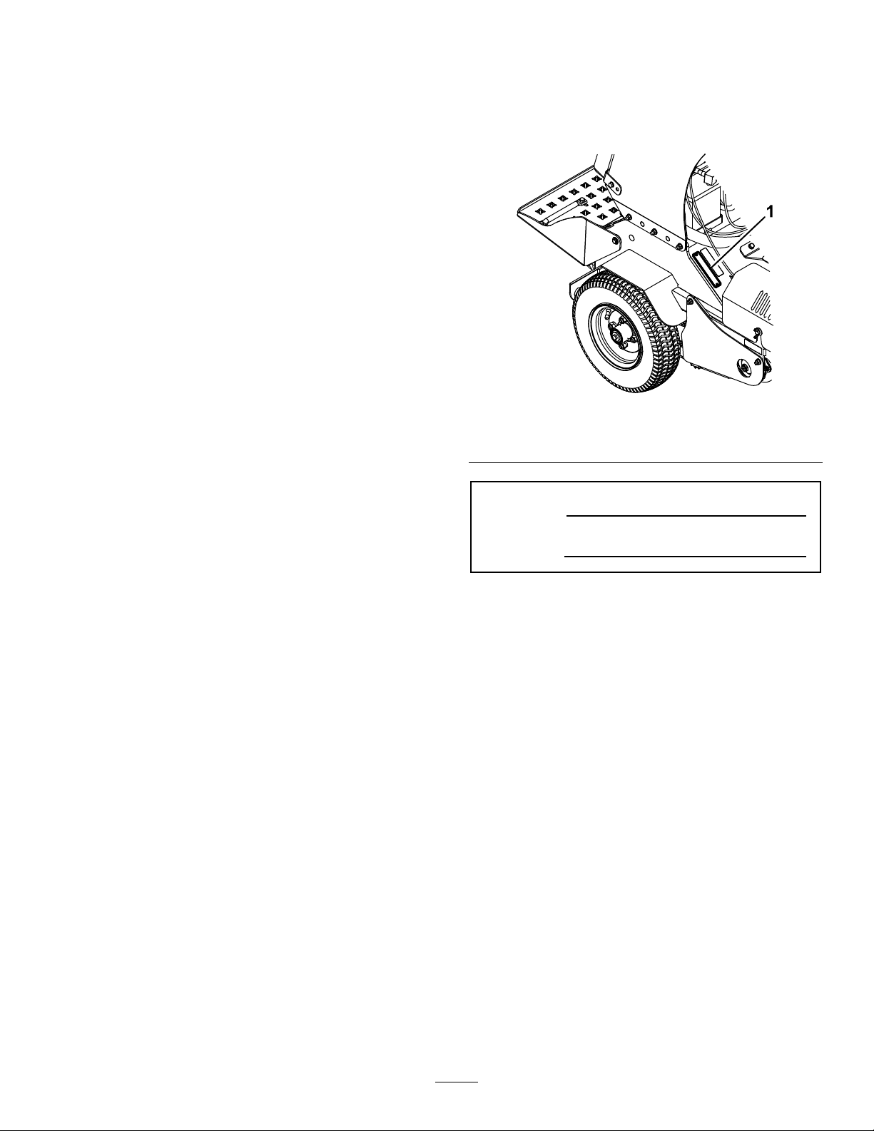
Figure1identiesthelocationofthemodelandserial
numbersontheproduct.Writethenumbersinthe
spaceprovided.
g231322
Figure1
1.Modelandserialnumberlocation
ModelNo.
SerialNo.
Forcompletewarrantydetails,see
http://www.Exmark.com.Youmayalsocall
us402-223-6375torequestawrittencopyofthe
product’swarranty.
Ifadditionalinformationisneeded,orshould
yourequiretrainedmechanicservice,contactyour
authorizedExmarkequipmentdealerordistributor.
AllExmarkequipmentdealersanddistributorsare
keptinformedofthelatestmethodsofservicing
andareequippedtoprovidepromptandefcient
serviceintheeldorattheirservicestations.They
carryamplestockofservicepartsorcansecurethem
promptlyforyoufromthefactory.
AllExmarkpartsarethoroughlytestedandinspected
beforeleavingthefactory,however,attentionis
requiredonyourpartifyouaretoobtainthefullest
measureofsatisfactionandperformance.
Wheneveryouneedservice,genuineExmarkparts,
oradditionalinformation,contactanAuthorized
ServiceDealerorExmarkCustomerServiceandhave
themodelandserialnumbersofyourproductready.
3
Page 4

Contents
Introduction...........................................................3
Safety.....................................................................5
SafetyAlertSymbol.........................................5
SafeOperatingPractices..................................5
SafetyandInstructionalDecals......................10
Specications........................................................14
Systems..........................................................14
Dimensions....................................................15
TorqueRequirements.....................................15
ProductOverview.................................................16
Operation..............................................................16
Controls.........................................................16
Pre-Start.........................................................20
OperatingInstructions...................................20
Transporting..................................................23
Maintenance..........................................................25
RecommendedMaintenanceSchedule(s)............25
PeriodicMaintenance........................................26
CheckEngineOilLevel..................................26
CheckBatteryCharge.....................................26
CheckTines...................................................28
ChecktheSafetyInterlock..............................29
CheckforLooseHardware.............................30
ServiceAirCleaner.........................................30
ChangeEngineOil.........................................30
CheckAuxiliaryHydraulicOilLevel................30
CheckHydraulicTransmissionOil
Level..........................................................30
CheckTirePressures......................................31
CheckConditionandTensionOf
Belts...........................................................31
CheckConditionOfChains............................31
CheckConditionOfSprockets.......................31
LubricatingtheChains....................................31
LubricatingtheGreaseFittings.......................31
CheckSparkPlug...........................................32
ChangeAuxiliaryHydraulicReservoirFluid
andFilter....................................................32
ChangeHydraulicTransmissionFiltersand
Fluid..........................................................32
CheckTransmissionOutputShaftNut
TorqueSpecication...................................33
CheckWheelHubBoltTorque
Specication...............................................33
CheckTransmissionMountBolt
Torque.......................................................33
CheckSparkArrester(ifequipped)..................34
ThreadLockingAdhesives..............................34
Adjustments......................................................35
AuxiliaryPumpDriveBeltAdjustment...........35
TransmissionDriveBeltTension....................35
DriveWheelChainTension
Adjustment................................................35
TineDriveChainAdjustment.........................35
AdjustingtheParkingBrake............................35
MotionControlLinkageAdjustment..............36
MotionControlTrackingAdjustment.............36
Return-to-UpSpringAdjustment....................37
Cleaning............................................................38
CleanEngineandExhaustSystem
Area...........................................................38
RemoveEngineShroudsandClean
CoolingFins...............................................38
CleanDebrisFromMachine...........................38
WasteDisposal...............................................38
Troubleshooting....................................................39
Schematics............................................................41
4
Page 5

Safety
Safety
SafetyAlertSymbol
ThisSafetyAlertSymbol(Figure2)isusedbothin
thismanualandonthemachinetoidentifyimportant
safetymessageswhichmustbefollowedtoavoid
accidents.
Thissymbolmeans:ATTENTION!BECOME
ALERT!YOURSAFETYISINVOLVED!
Figure2
SafetyAlertSymbol
Thesafetyalertsymbolappearsaboveinformation
whichalertsyoutounsafeactionsorsituations
andwillbefollowedbythewordDANGER,
WARNING,orCAUTION.
DANGER:Indicatesanimminentlyhazardous
situationwhich,ifnotavoided,Willresultindeathor
seriousinjury.
•Alloperatorsandmechanicsshouldbetrained.
Theownerisresponsiblefortrainingtheusers.
•Neverletchildrenoruntrainedpeopleoperate
orservicetheequipment.Localregulationsmay
restricttheageoftheoperator.
•Onlyadultsandmatureteenagersshouldoperate
anaerator,andevenmatureteenagersshouldhave
adultsupervision.Besureateenager:
1.hasreadandunderstandstheOperator's
Manualandrecognizestherisksinvolved;
2.issufcientlymaturetousecaution;and
g000502
3.isofsufcientsizeandweighttooperate
thecontrolscomfortablyandtomanagethe
aeratorwithouttakingrisks.
•Theowner/usercanpreventandisresponsible
foraccidentsorinjuriesoccurringtohimselfor
herself,otherpeopleorproperty.
Preparation
•Evaluatetheterraintodeterminewhataccessories
andattachmentsareneededtoproperlyand
safelyperformthejob.Onlyuseaccessoriesand
attachmentsapprovedbyExmark.
WARNING:Indicatesapotentiallyhazardous
situationwhich,ifnotavoided,Couldresultindeath
orseriousinjury.
CAUTION:Indicatesapotentiallyhazardous
situationwhich,ifnotavoided,Mayresultinminor
ormoderateinjury.
Thismanualusestwootherwordstohighlight
information.Importantcallsattentiontospecial
mechanicalinformationandNoteemphasizes
generalinformationworthyofspecialattention.
SafeOperatingPractices
Training
•ReadtheOperator’sManualandothertraining
material.Iftheoperator(s)ormechanic(s)cannot
readthismanualitistheowner’ sresponsibilityto
explainthismaterialtothem;otherlanguagesmay
beavailableonourwebsite.
•Becomefamiliarwiththesafeoperationofthe
equipment,operatorcontrols,andsafetysigns.
•Wearappropriateclothingincludingsafetyglasses,
substantialslip-resistantfootwear,andhearing
protection.Longhair,looseclothingorjewelry
maygettangledinmovingparts.
CAUTION
Thismachineproducessoundlevelsinexcess
of85dBAattheoperator’searandcancause
hearinglossthroughextendedperiodsof
exposure.
Wearhearingprotectionwhenoperatingthis
machine.
•Inspecttheareawheretheequipmentistobe
usedandremoveallrocks,toys,sticks,wires,
bones,andotherforeignobjectswhichcanbe
thrownbythemachineandmaycausepersonal
injurytotheoperatororbystanders.
•Markandavoidhiddenobjectssuchassprinkler
heads,undergroundwires/cables,invisiblefences,
etc.topreventdamagetothesesystemswhen
aerating.
5
Page 6

Safety
DANGER
Incertainconditionsgasolineisextremely
ammableandvaporsareexplosive.
Areorexplosionfromgasolinecanburn
you,others,andcausepropertydamage.
•Fillthefueltankoutdoorsonlevelground,
inanopenarea,whentheengineiscold.
Wipeupanygasolinethatspills.
•Neverrellthefueltankordrainthe
machineindoorsorinsideanenclosed
trailer.
•DoNotllthefueltankcompletelyfull.
Fillthefueltanktothebottomoftheller
neck.Theemptyspaceinthetankallows
gasolinetoexpand.Overllingmayresult
infuelleakageordamagetotheengine
oremissionsystem.
•Neversmokewhenhandlinggasoline,and
stayawayfromanopenameorwhere
gasolinefumesmaybeignitedbyspark.
•Storegasolineinanapprovedcontainer
andkeepitoutofthereachofchildren.
•Addfuelbeforestartingtheengine.Never
removethecapofthefueltankoradd
fuelwhenengineisrunningorwhenthe
engineishot.
DANGER
Incertainconditionsduringfueling,static
electricitycanbereleasedcausingaspark
whichcanignitegasolinevapors.Areor
explosionfromgasolinecanburnyouand
othersandcausepropertydamage.
•Alwaysplacegasolinecontainersonthe
groundawayfromyourvehiclebefore
lling.
•DoNotllgasolinecontainersinsidea
vehicleoronatruckortrailerbedbecause
interiorcarpetsorplastictruckbedliners
mayinsulatethecontainerandslowthe
lossofanystaticcharge.
•Whenpractical,removegas-powered
equipmentfromthetruckortrailerand
refueltheequipmentwithitswheelson
theground.
•Ifthisisnotpossible,thenrefuelsuch
equipmentonatruckortrailerfroma
portablecontainer,ratherthanfroma
gasolinedispensernozzle.
•Ifagasolinedispensernozzlemustbe
used,keepthenozzleincontactwiththe
rimofthefueltankorcontaineropening
atalltimesuntilfuelingiscomplete.Do
Notuseanozzlelockopendevice.
•Iffuelisspilled,DoNotattempttostart
theengine.Moveawayfromtheareaof
thespillandavoidcreatinganysourceof
ignitionuntilfuelvaporshavedissipated.
•DoNotoperatewithoutentireexhaust
systeminplaceandinproperworking
condition.
WARNING
Gasolineisharmfulorfatalifswallowed.
Long-termexposuretovaporshascaused
cancerinlaboratoryanimals.Failuretouse
cautionmaycauseseriousinjuryorillness.
•Avoidprolongedbreathingofvapors.
•Keepfaceawayfromnozzleandgas
tank/containeropening.
•Keepawayfromeyesandskin.
•Neversiphonbymouth.
•Checkthattheoperatorpresencecontrols,
safetyswitches,andshieldsareattachedand
functioningproperly.DoNotoperateunlessthey
arefunctioningproperly.
6
Page 7

Safety
Operation
WARNING
Operatingengineparts,especiallythemufer,
becomeextremelyhot.Severeburnscanoccur
oncontactanddebris,suchasleaves,grass,
brush,etc.cancatchre.
•Allowengineparts,especiallythemufer,to
coolbeforetouching.
•Removeaccumulateddebrisfrommuferand
enginearea.
WARNING
Engineexhaustcontainscarbonmonoxide,
whichisanodorlessdeadlypoisonthatcankill
you.
DoNotrunengineindoorsorinasmallconned
areawheredangerouscarbonmonoxidefumes
cancollect.
•Operateonlyindaylightorgoodarticiallight,
keepingawayfromholesandhiddenhazards.
•Lightningcancausesevereinjuryordeath.If
lightningisseenorthunderisheardinthearea,
DoNotoperatethemachine;seekshelter.
•Besurealldrivesareinneutralandparkingbrake
isengagedbeforestartingengine.
•Neveroperatethemachinewithdamagedguards,
shields,orcovers.Alwayshavesafetyshields,
guards,switchesandotherdevicesinplaceandin
properworkingcondition.
•DoNotchangetheenginegovernorsettingor
overspeedtheengine.
•Parkmachineonlevelground.Stopengine,wait
forallmovingpartstostop,removekeyand
engageparkingbrake:
–Beforechecking,cleaningorworkingonthe
machine.
–Afterstrikingaforeignobjectorabnormal
vibrationoccurs(inspectthemachinefor
damageandmakerepairsbeforerestarting
andoperatingthemachine).
–Beforeclearingblockages.
–Wheneveryouleavethemachine.
•Stopengine,waitforallmovingpartstostop,and
engageparkingbrake:
–Beforerefueling.
WARNING
Hands,feet,hair,clothing,oraccessoriescan
becomeentangledinrotatingparts.Contact
withtherotatingpartscancausetraumatic
amputationorseverelacerations.
•DoNotoperatethemachinewithout
guards,shields,andsafetydevicesinplace
andworkingproperly.
•Keephands,feet,hair,jewelry,orclothing
awayfromrotatingparts.
•NEVERcarrypassengers.DONOToperate
themachinewhenpeople,especiallychildren,or
petsareinthearea.
•Bealert,slowdownandusecautionwhen
makingturns.Lookbehindandtothesidebefore
changingdirections.
•Raisethetines,slowdown,andusecautionwhen
crossingsurfacesotherthangrassandwhen
transportingthemachinetoandfromthework
area.
•DoNotoperatethemachineundertheinuence
ofalcoholordrugs.
•Useextremecarewhenloadingorunloadingthe
machineintoatrailerortruck.
•Usecarewhenapproachingblindcorners,shrubs,
trees,orotherobjectsthatmayobscurevision.
SlopeOperation
•Slopesareamajorfactorrelatedtolossofcontrol
androlloveraccidents,whichcanresultinsevere
injuryordeath.Theoperatorisresponsiblefor
safeslopeoperation.Operatingthemachineon
anysloperequiresextracaution.Beforeusingthe
machineonaslope,theoperatormust:
–Reviewandunderstandtheslopeinstructions
inthemanualandonthemachine.
–Evaluatethesiteconditionsofthedayto
determineiftheslopeissafeformachine
operation.Usecommonsenseandgood
judgmentwhenperformingthisevaluation.
Changesintheterrain,suchasmoisture,can
quicklyaffecttheoperationofthemachine
onaslope.
•Operateacrossslopes,neverupanddown.Avoid
operationonexcessivelysteeporwetslopes.
7
Page 8
Safety
•Identifyhazardsatthebaseoftheslope.Do
notoperatethemachineneardropoffs,ditches,
embankments,waterorotherhazards.The
machinecouldsuddenlyrolloverifawheelgoes
overtheedgeortheedgecollapses.Keepasafe
distance(twicethewidthofthemachine)between
themachineandanyhazard.Useawalkbehind
machineorahandheldtooltooperateinthese
areas.
•Useextracarewhileoperatingwithaccessories
orattachments.Thesecanchangethestabilityof
themachineandcausealossofcontrol.Follow
directionsforcounterweights.
•Ifyoulosecontrolofthemachine,stepoffand
awayfromthedirectionoftravelofthemachine.
MaintenanceandStorage
•Raisethetines,settheparkingbrake,stopengine
andremovekeyordisconnectsparkplugwire.
Waitforallmovementtostopbeforeadjusting,
cleaningorrepairing.
•Keepengineandengineareafreefromexcessive
greaseoroilandotherdebriswhichcan
accumulateintheseareas.Thesematerialscan
becomecombustibleandmayresultinare.
•Letenginecoolbeforestoringanddonotstore
nearameoranyenclosedareawhereopenpilot
lightsorheatappliancesarepresent.
•Shutofffuelwhilestoringortransporting.Do
Notstorefuelnearamesordrainindoors.
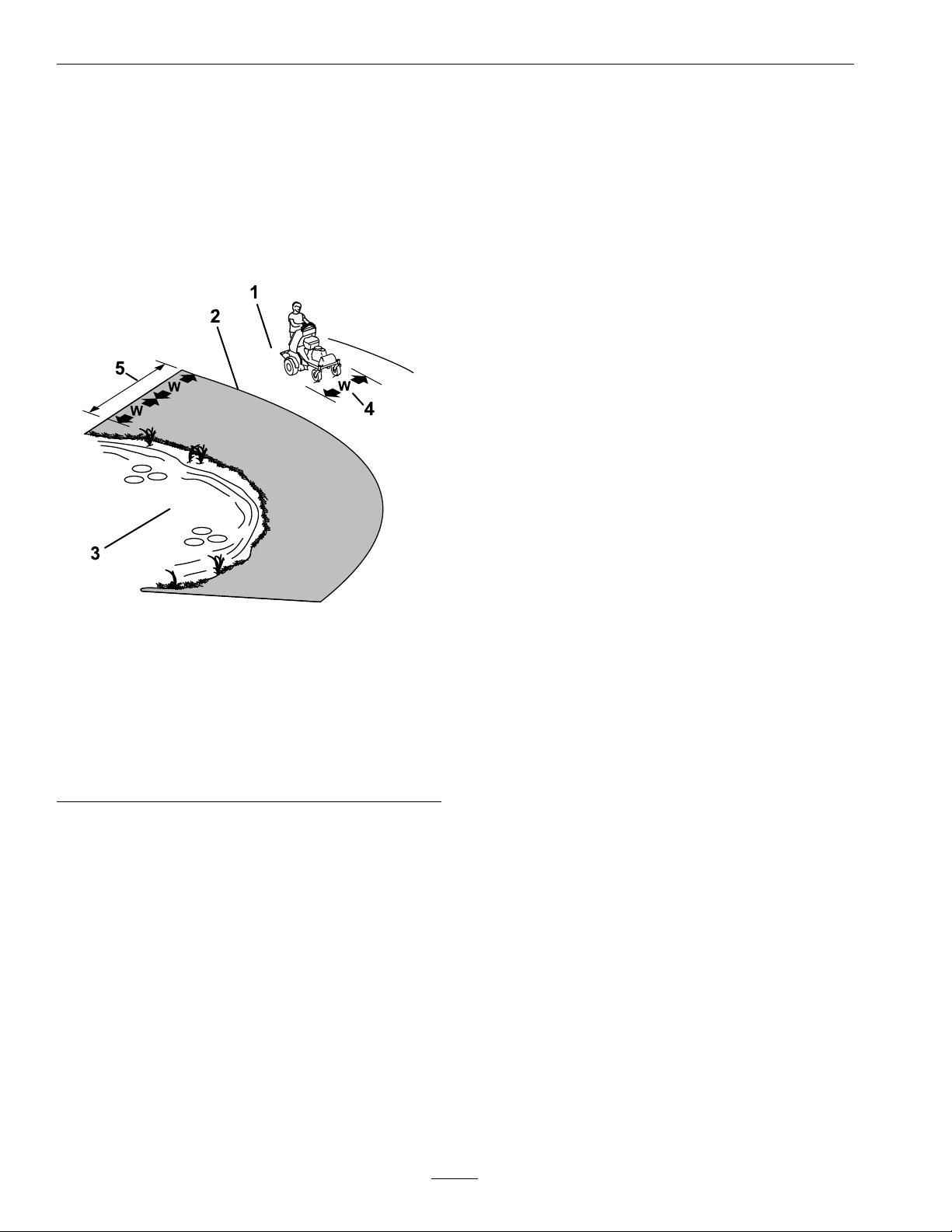
Figure3
1.SafeZone—Usethemachinehere
2.DangerZone-Useawalkbehindmachineorahand
heldtoolneardropoffs,ditches,embankments,water
orotherhazards.
3.Water
4.W=widthofthemachine
5.Keepasafedistance(twicethewidthofthemachine)
betweenthemachineandanyhazard.
•Avoidstarting,stoppingorturningthemachine
onslopes.Avoidmakingsuddenchangesinspeed
ordirection;turnslowlyandgradually.
•Donotoperateamachineunderanyconditions
wheretraction,steeringorstabilityisinquestion.
Beawarethatoperatingthemachineonwetgrass,
acrossslopesordownhillmaycausethemachine
tolosetraction.Lossoftractiontothedrive
wheelsmayresultinslidingandalossofbraking
andsteering.Themachinecanslideevenifthe
drivewheelsarestopped.
•Removeormarkobstaclessuchasditches,holes,
ruts,bumps,rocksorotherhiddenhazards.Tall
grasscanhideobstacles.Uneventerraincould
overturnthemachine.
g222486
•Parkmachineonlevel,hardground.Neverallow
untrainedpersonneltoservicemachine.
•Usejackstandstosupportcomponentswhen
required.
•Carefullyreleasepressurefromcomponentswith
storedenergy.
•Disconnectbatteryorremovesparkplugwire
beforemakinganyrepairs.Disconnectthe
negativeterminalrstandthepositivelast.
Reconnectpositiverstandnegativelast.
•Usecarewhencheckingandservicingtines.Wrap
thetine(s)orweargloves,andusecautionwhen
servicingthem.Onlyreplacedamagedtines.
Neverstraightenorweldthem.
•Keephandsandfeetawayfrommovingparts.
Ifpossible,donotmakeadjustmentswiththe
enginerunning.
•Chargebatteriesinanopenwellventilatedarea,
awayfromsparkandames.Unplugcharger
beforeconnectingordisconnectingfrombattery.
Wearprotectiveclothinganduseinsulatedtools.
8
Page 9

Safety
DANGER
Chargingorjumpstartingthebatterymay
produceexplosivegases.Batterygasescan
explodecausingseriousinjury.
•Keepsparks,ames,orcigarettesaway
frombattery.
•Ventilatewhenchargingorusingbattery
inanenclosedspace.
•Makesureventingpathofbatteryis
alwaysopenoncebatteryislledwith
acid.
•Alwaysshieldeyesandfacefrombattery.
DANGER
Batteryelectrolytecontainssulfuricacid,
whichispoisonousandcancausesevere
burns.Swallowingelectrolytecanbefatalor
ifittouchesskincancausesevereburns.
•Wearsafetyglassestoshieldeyes,and
rubberglovestoprotectskinandclothing
whenhandlingelectrolyte.
•DoNotswallowelectrolyte.
•Intheeventofanaccident,ushwith
waterandcalladoctorimmediately.
WARNING
Removingstandardoriginalequipmentparts
andaccessoriesmayalterthewarranty,traction,
andsafetyofthemachine.Failuretouseoriginal
Exmarkpartscouldcauseseriousinjuryor
death.Makingunauthorizedchangestothe
engine,fuelorventingsystem,mayviolateEP A
andCARBregulations.
Replaceallpartsincluding,butnotlimitedto,
tires,belts,tines,andfuelsystemcomponents
withoriginalExmarkparts.
WARNING
Hydraulicuidescapingunderpressure
canpenetrateskinandcauseinjury.Fluid
accidentallyinjectedintotheskinmustbe
surgicallyremovedwithinafewhoursbyadoctor
familiarwiththisformofinjuryorgangrenemay
result.
•Ifequipped,makesureallhydraulicuid
hosesandlinesareingoodconditionandall
hydraulicconnectionsandttingsaretight
beforeapplyingpressuretohydraulicsystem.
•Keepbodyandhandsawayfrompinhole
leaksornozzlesthatejecthighpressure
hydraulicuid.
CAUTION
Iftheignitionisinthe“ON”positionthere
ispotentialforsparksandengagementof
components.Sparkscouldcauseanexplosion
ormovingpartscouldaccidentallyengage
causingpersonalinjury.
Besureignitionswitchisinthe“OFF”
positionbeforechargingthebattery.
•Keepallguards,shieldsandallsafetydevicesin
placeandinsafeworkingcondition.
•Checkallboltsfrequentlytomaintainproper
tightness.
•Frequentlycheckforwornordeteriorating
componentsthatcouldcreateahazard.
•Usecardboardorpaper,notyourhands,to
ndhydraulicleaks.
•Beforeperforminganyworkonthehydraulic
system:
–Safelyrelieveallpressureintheground
drivehydraulicsystembyplacingthemotion
controlleversinneutralandshuttingoffthe
engine.
–Safelyrelieveallpressureintheauxiliary
hydraulicsystembyshuttingofftheengine,
turningtheignitionswitchtothe“ON”
position,andpressingthetineground
engagementswitch.Oncethetineshave
loweredtotheground,releasethetineground
engagementswitchandturntheignition
switchtothe“OFF”position.
9
Page 10
Safety
SafetyandInstructionalDecals
•Keepallsafetysignslegible.Removeallgrease,
dirtanddebrisfromsafetysignsandinstructional
labels.
•Replaceallworn,damaged,ormissingsafety
signs.
•Whenreplacementcomponentsareinstalled,be
surethatcurrentsafetysignsareafxedtothe
replacedcomponents.
•Ifanattachmentoraccessoryhasbeeninstalled,
makesurecurrentsafetysignsarevisible.
•Newsafetysignsmaybeobtainedfrom
yourauthorizedExmarkequipmentdealeror
distributororfromExmarkMfg.Co.Inc.
•Safetysignsmaybeafxedbypeelingoffthe
backingtoexposetheadhesivesurface.Apply
onlytoaclean,drysurface.Smoothtoremove
anyairbubbles.
•Familiarizeyourselfwiththefollowingsafetysigns
andinstructionlabels.Theyarecriticaltothesafe
operationofyourExmarkcommercialaerator.
115-4212
1.Hydraulicoillevel3.Warning—donottouch
thehotsurface.
2.ReadtheOperator's
Manual.
117–2718
120-9570
1.Warning—stayawayfrommovingparts,keepallguards
andshieldsinplace.
decal115-4212
decal121-6150
121-6150
1.Cuttinghazardofhandandfoot–stayawayfrommoving
parts.
decal117-2718
decal121-6161
121–6161
1.Entanglementhazard,belt—stayawayfrommoving
parts;keepallguardsinplace.
decal120-9570
10
Page 11
Safety
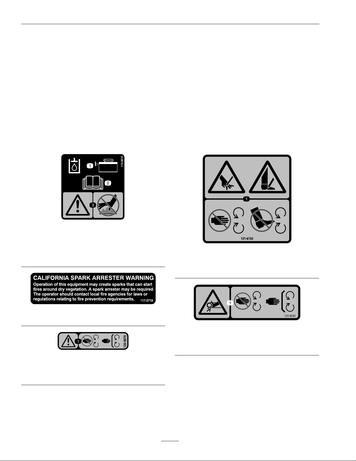
decal135-3183
135-3183
121–6163
1.Presstolowerthetines.2.Releasetoraisethe
tines.
1.Bypassleverpositionfor
pushingthemachine.
3.Bypassleverpositionfor
operatingthemachine.
2.Readtheinstructions
decal121-6163
beforeservicingor
performingmaintenance.
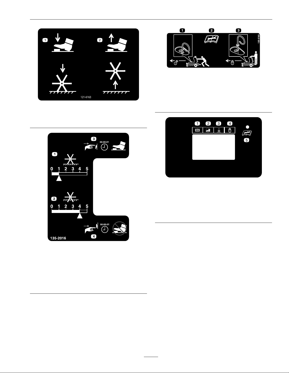
g211619
HourMeter/TineEngagementDisplay
1.Parkingbrake4.Depthsettinglock
2.Tinegroundengagement
footswitchlockout
3.Tinedownposition
5.SeeOperator’smanual
foroperatingconditions
code
135-2016
1.Electronictinedepth-decrease
2.Electronictinedepth-increase
3.Pressandhold1secondtoturnon—tineground
engagementfootswitchunlock
4.Pressandhold1secondtoturnoff—tineground
engagementfootswitchlock
decal135-2016
11
Page 12
Safety
STOP
LB
KG
135-2013
2
1
3
4
5
6
7
8
9
10
decal135-2013-1
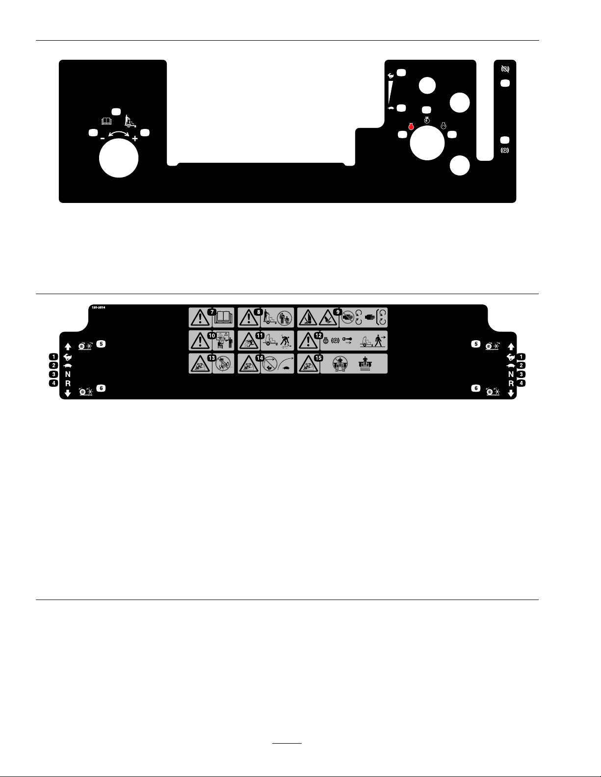
135-2013
1.Operatorweightadjustment
5.Throttle—slow9.Parkingbrake—engage
2.Increase6.Engine—on10.Parkingbrake—release
3.Decrease7.Engine—start
4.Throttle—fast8.Engine—off
135-2014
1.Fast6.Wheelsandtinesrotatewhen
2.Slow7.Warning—readtheOperator’s
3.Neutral
4.Reverse
5.Wheelsandtinesrotatewhen
movingforward
movingbackward
Manual.
8.Warning—keepbystandersasafe
distanceawayfromthemachine.
9.Warning—Cutting/dismemberment
hazardofhandorfoot;tines—stay
awayfrommovingparts;keepall
guardsinplace.
10.Warning—Donotoperatethe
machineunlessyouaretrained.
decal135-2014b
11.Thrownobjecthazard—pickup
debrisbeforeoperatingthemachine.
12.Warning—shutofftheengine,
engagetheparkingbreak,and
removetheignitionkeybefore
leavingthemachine.
13.Tippinghazard–DoNotoperatethe
machineneardrop-offs.
14.Tippinghazard–DoNotturnsharply
whiletravelingfast;slowdownand
turngradually.
15.Tippinghazard–DoNotusesplit
ramps;usefullwidthrampstoload
amachinefortransport.
12
Page 13
Safety
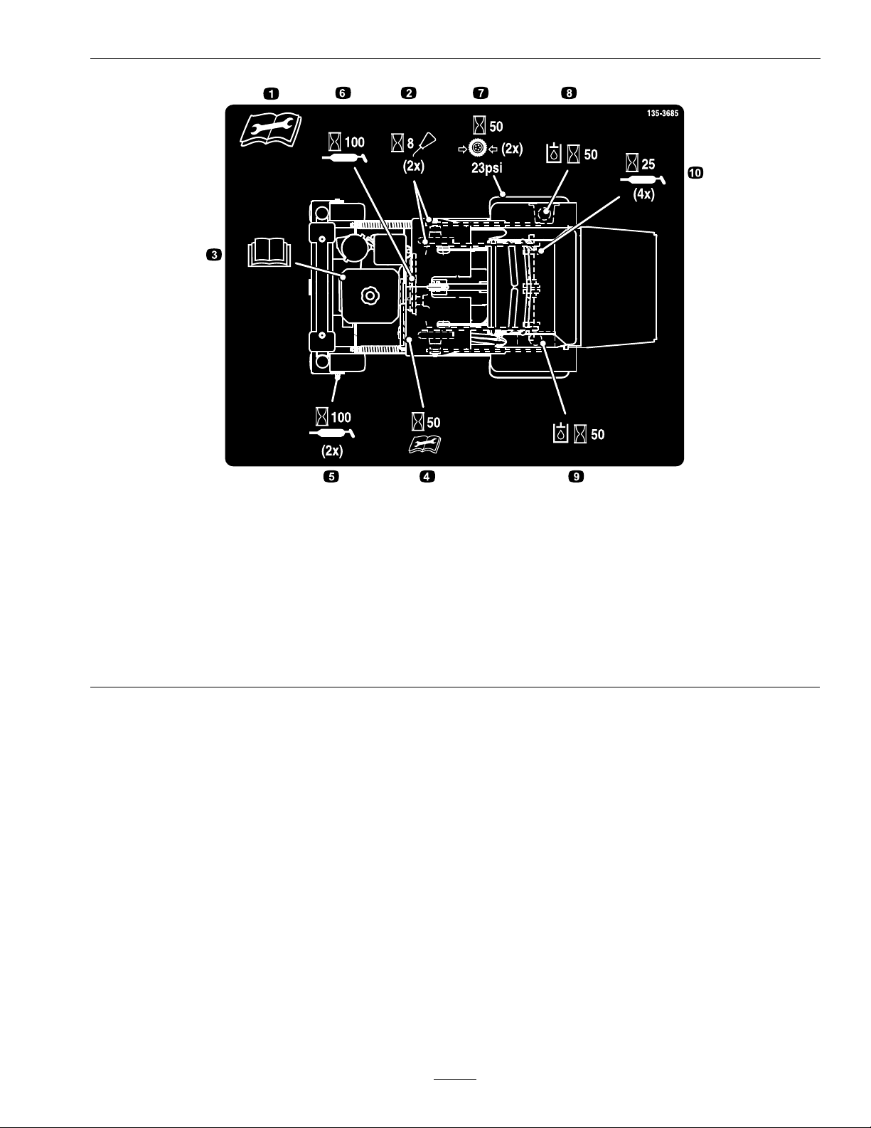
135-3685
1.Readandunderstandtheoperator’smanualbefore
servicingthismachine.
2.Cleanandoilchainsandcheckchaintension(2x)every8
hours
3.Seeengineowner’smanualforservice8.Checkhydraulicoillevel(2x)(Onlyuserecommended
4.Checkauxiliarypumpdrivebelttensionevery50hours9.Checkauxiliaryhydraulictank(OnlyuseAW-32hydrooil)
5.Greasefrontcasterwheelbearings(2x)every100hours10.Greasetineshaftbearings(4x)every25hours
6.Greasebeltidlerpivotevery100hours
7.Checktirepressure-23psi(2x)every50hours
hydrooil)every50hours
every50hours
decal135-3685
13
Page 14

Specications
Specications
Systems
Engine
•EngineSpecications:SeeyourEngineOwner’s
Manual
•EngineOilType:Exmark4–CyclePremium
EngineOil
•RPM:FullSpeed:3800±100RPM(NoLoad)
FuelSystem
•Capacity:1.9gal.(7L)
•FuelRecommendations:
–Forbestresults,useonlyclean,fresh,unleaded
gasolinewithanoctaneratingof87orhigher
((R+M)/2ratingmethod).
–Oxygenatedfuelwithupto10%ethanolor
15%MTBEbyvolumeisacceptable.
–DoNotuseethanolblendsofgasoline(such
asE15orE85)withmorethan10%ethanol
byvolume.Performanceproblemsand/or
enginedamagemayresultwhichmaynotbe
coveredunderwarranty.
–DoNotusegasolinecontainingmethanol.
OperatorControls
•SteeringandMotionControl
–Separatelevers,oneachsideoftheconsole,
controlspeedanddirectionoftravelofthe
respectivedrivewheels.
–Steeringiscontrolledbyvaryingtheposition
oftheleversrelativetoeachother.
•TineGroundEngagement:Engagesthetines
withtheground.
•ParkingBrakeLever:Engagestheparkingbrake.
•TineDownPressureControl:Adjuststinedown
pressure.
•ElectronicDepthControl:Adjustsactualtine
depthelectronically.
Transmission
•Twointegratedhydrostatictransmissions:Hydro
GearZT3100.
•HydraulicOilCapacity:78oz.(2.3L)per
transmission
•HydraulicFilterisreplaceablecartridgetype
•Speeds:
–0-7.0mph(11.3km/hr)forward.
–0-4.0mph(6.4km/hr)reverse.
–DoNotstorefueleitherinthefueltankor
fuelcontainersoverthewinterunlessafuel
stabilizerisused.
–DoNotaddoiltogasoline.
•FuelShut-OffValve:1/4turn
ElectricalSystem(ElectricStart)
•ChargingSystem:FlywheelAlternator
•ChargingCapacity:Kohler,10amps
•BatteryType:BCIGroupU1
•BatteryVoltage:12Volt
•Polarity:NegativeGround
•Fuse:20ampmainfuse
SafetyInterlockSystem
Enginewillnotstartunlesstheparkbrakeisengaged.
WheelandTineDriveSystem
Drivewheelsandtheoutsideaerationtinesare
driventhroughrollerchainsbythetwohydrostatic
transmissions.
14
Page 15

Specications
TiresandWheels
Drive
Pneumatic
(Air-Filled)
Quantity
Tread
Size16.5x4.50-8113x4.00-6
PlyRating
Pressure
22
TurfSaverSmooth
4
23psi
(159kPa)
Aeration
AerationWidth:24inches(61.0cm)
Tines:Qty:36
CoreDepth:.5-5inches(1.3-12.7cm)
Holespersquarefoot:4.6
TorqueRequirements
FrontCaster
Semi-Pneumatic
BoltLocation
EngineMountingBolts
WheelLugNuts
WheelHubBolt27-33ft-lb(37-45N-m)
TransmissionOutput
ShaftNuts
TineShaftNut
WheelAxleBolt135-165ft-lb
TransmissionBracket
Bolts(4xwithspacers)
Torque
27-33ft-lb(37-45N-m)
85-105ft-lb(115-142
N-m)
211-260ft-lb
(286-352N-m)
211-260ft-lb
(286-352N-m)
(183-224N-m)
38-48ft-lb
(52-65N-m)
Dimensions
OverallWidth:
35.5inches(90.2cm)
OverallLength:
68.6inches(173.2cm)
OverallHeight:
51.0inches(129.5cm)
TreadWidth:(OutsidetoOutsideof
Tires,Widthwise)
35.5inches(90.2cm)
CurbWeight:
856lb(388kg)
15
Page 16

Operation
ProductOverview
Figure4
1.Platform
2.Parkbrakelever5.Fuelcap
3.Enginecontrols
4.Motioncontrollevers
Operation
Note:Determinetheleftandrightsidesofthe
machinefromthenormaloperatingposition.
Controls
MotionControlLevers
Themotioncontrollevers,locatedoneachsideofthe
topconsole,controltheforwardandreversemotion
ofthemachine.
Movingtheleversforwardorbackwardturns
thewheelonthesamesideforwardorreverse
respectively.Wheelspeedisproportionaltothe
amounttheleverismoved.
g231324
Important:Thetinesarerotatingwhenthe
motioncontrolleversaremovedoutofthe
neutralposition.
Figure5
1.LHMotioncontrollever5.Forward
2.RHMotioncontrollever6.Neutral
3.Frontreferencebar
4.Frontofunit8.Rearreferencebar
7.Reverse
ChokeControl
Locatedonthecontrolconsole(blackknob)(see
Figure6).
Thechokeisusedtoaidinstartingacoldengine.
Pullingthechokeknobupwardwillputthechoke
inthe“ON”positionandpushingthechokeknob
downward,willputthechokeinthe“OFF”position.
16
g223330
Page 17

Operation
DoNotrunawarmenginewithchokeinthe“ON”
position.
Pullleverrearwardtoengagethebrake.
Pushtheleverforwardtodisengagethebrake.
Whenparkingonasteepslope,thewheelsmustbe
chockedorblockedinadditiontothebrakebeing
engaged.Theunitmustbetieddownandbrake
engagedwhentransporting.
IgnitionSwitch
Locatedontherightsideofthecontrolconsole.
Theignitionswitchisusedtostartandstopthe
engine.Theswitchhasthreepositions“OFF”,“ON”
and“START”.Insertkeyintoswitchandrotate
clockwisetothe“ON”position.Rotateclockwiseto
thenextpositiontoengagethestarter(keymustbe
heldagainstspringpressureinthisposition).Allow
thekeytoreturntothe“ON”positionimmediately
aftertheenginestarts.
Figure6
1.Tinegroundengagement
footswitch
2.Operatorweight
adjustmentcontrol
3.Multi-functionswitch
4.LHMotioncontrollever10.Parkbrake
5.Frontreferencebar
6.Throttle
7.Choke
8.RHMotioncontrollever
9.Hourmeter
11.Ignitionswitch
ThrottleControl
Locatedonthecontrolconsole(redlever)(see
Figure6).
Thethrottleisusedtocontrolenginespeed.Moving
thethrottleleverforwardwillincreaseenginespeed
andmovingthethrottlelevertotherearwilldecrease
enginespeed.Movingthethrottleforwardintothe
detentisfullthrottle.
g231368
g008610
Figure7
1.Off3.Start
2.On
Note:Tostarttheengine,theparkingbrakemust
beengaged.(Itisnotnecessaryfortheoperatorto
beontheplatform.)
HourMeter/TineEngagementDisplay
Locatedtotheleftoftheignitionswitchonthe
controlconsole.
•Thehourmetermonitorsanddisplaysengine
hours.
ParkBrakeLever
Locatedontherightsideoftheignitionswitchon
thecontrolconsole.
Thebrakeleverengagesaparkingbrakeinthe
transmissions.
17
Page 18

Operation
Therearetwowaystoactivatethedisplay .
1.Tapthemulti-functionswitcheitherupordown
todisplaythetineengagementmeter.
2.Steponthetinegroundengagementfootswitch.
Ahighernumberonthestatusbarincreasesthe
lengthoftheaerationplugandalowernumber
decreasesit.
Note:Ifthepluglengthisnotdesiredlength,the
machinemayneedtobeadjustedtoaccommodate
g211730
Figure8
HourMeterDisplay
fortheweightoftheoperator(refertotheOperator
WeightAdjustmentControlsectionformore
information).
1.LCDIndicators/Informationscreen
2.Hourdisplay
3.LEDstatuslight
Hoursaredisplayedwhenthekeyisofforwhen
themachineisrunning.Hoursarenotdisplayed
whenthemachineisaerating.
Note:TheLCDindicatorwillappearinthepark
brakesettingwhenitmeetsthe“safetostart”
mode(parkbrakeengaged).
•Thetineengagementdisplaymonitorsand
displaystheelectronictinedepthsetting.
Note:RefertotheHourMeter/TineEngagement
User’sGuidefordetailedinformationexplaining
theOperatorinterfaceallowinguserstoaccess
information,resetcounters,modifysystemsettings,
andtroubleshoottheequipment.
LEDStatusLights
Locatedontherightsideofthehourmeter/tine
engagementdisplay.
TheLEDismulti-coloredtoindicatethesystem
statusandislocatedontherightsideofthepanel.
•SolidGreen—indicatesnormaloperating
activity.
•BlinkingRed—indicatesafaultisactive.
•SolidRed—indicatesmaintenanceisrequired.
Note:RefertotheHourMeter/TineEngagement
User’sGuideformoreinformation.
Multi-FunctionSwitch
TineEngagementDisplay
1.LCDIndicators/Informationscreen
2.Tinedepthstatusbar
3.Tinedepthsettingindicator
4.LEDstatuslight
Figure9
Locatedtotheleftofthehourmeter/tineengagement
display.
g211731
Thisswitchallowstheoperatorto:
•increase/decreasethedepthofaerationplug.
•lockorunlockthetinedepthsetting.
•lockorunlocktheTineGroundEngagement
FootSwitch.
FuelShut-OffLever
LocatedundertheaircleaneronthefrontRHside.
Thefuelshut-offleverisusedtoshutoffthefuel
whenthemachinewillnotbeusedforafewdays,
18
Page 19
duringtransporttoandfromthejobsite,andwhen
parkedinsideabuilding.
Rotatethehandlecounterclockwisetoopen;rotate
clockwiseto90°toclose.
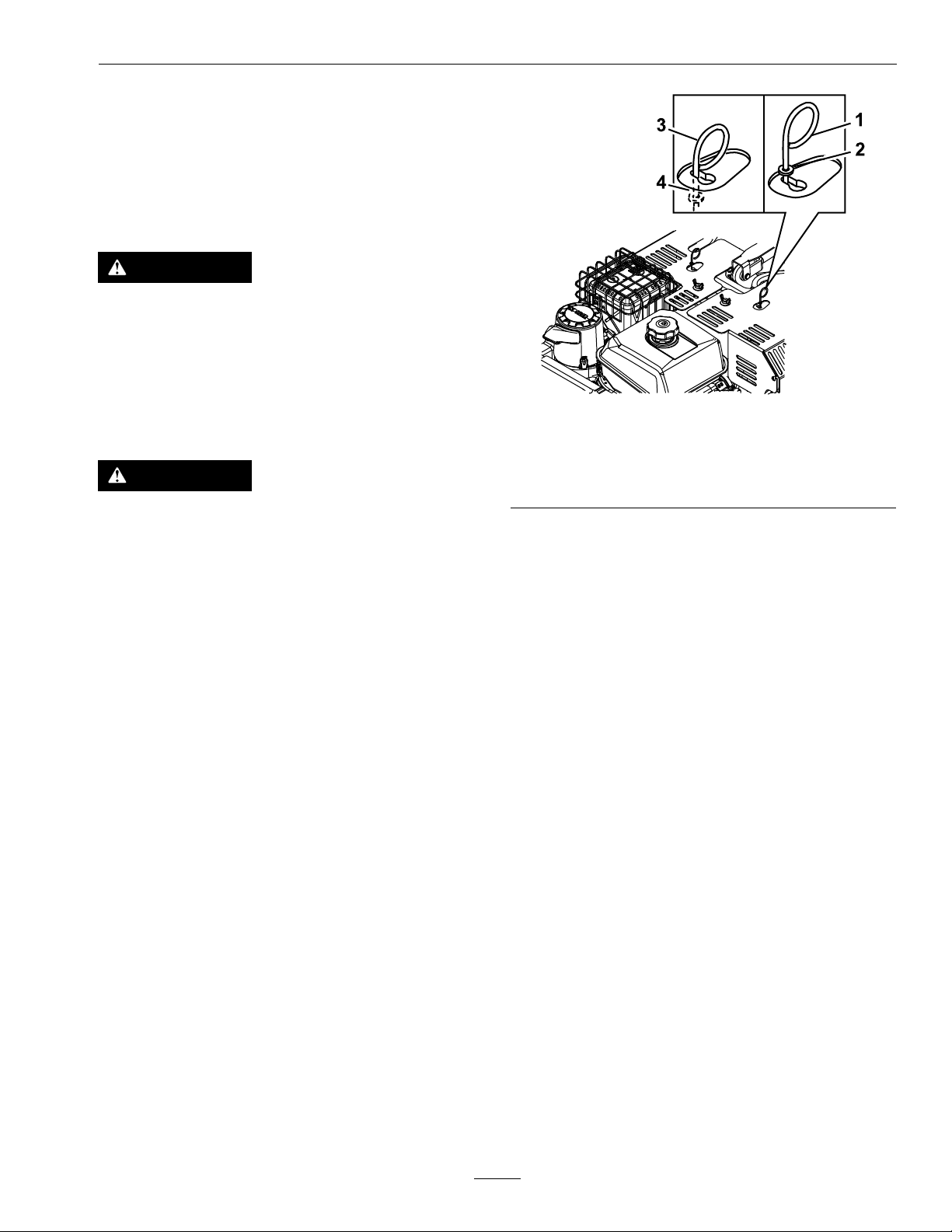
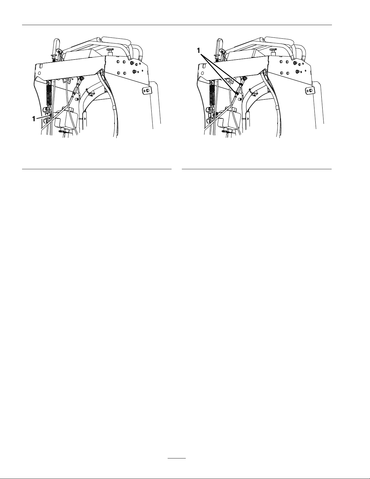
DriveWheelReleaseValves
WARNING
Handsmaybecomeentangledintherotating
drivecomponentsbelowtheenginedeck,which
couldresultinseriousinjuryordeath.
Stopengine,removekey,allowallthemoving
partstostopbeforeaccessingthedrivewheel
releasevalves.
Operation
g211754
Figure10
WARNING
Theengineandhydraulicdriveunitscanbecome
veryhot.T ouchingahotengineorhydraulic
driveunitscancausesevereburns.
Allowtheengineandhydraulicdriveunitsto
coolcompletelybeforeaccessingthedrivewheel
releasevalves.
Locatedontheleftandrightsidesabovethe
transaxles.
Duringnormaloperatingconditions,thewasher
ontheleverispositionedoutsidetheslots.Ifthe
machinehastobepushedbyhand,thevalvesmust
beinthe“released”position(seeFigure10).
1.Leverpositionfor
operatingthemachine
2.Washeroutsideofslot
3.Leverpositiontopush
themachine
4.Washerinsideslot
Toreleasethedrivewheels,movethelevertothe
largeropeningoftheslot,pushitinuntilthewasher
isinsidetheframe,thenmovetheleverbacktothe
narrowportionoftheslot.Repeatthisoneachside
ofthemachine.
Releasetheparkingbrake.Themachineisnowable
tobepushedbyhand.
DoNottowmachine.
Toresetthedrivesystembacktotheoperating
position:movethelevertothelargeropeningof
theslot,pulloutwarduntilthewasherisoutsideof
theframe,thenmovetheleverbacktothenarrow
portionoftheslot.Repeatthisoneachsideofthe
machine.
TineGroundEngagementFoot
Switch
Keephandsandfeetawayfromthetines.Ensure
thatthetinesareaisclearofanyobstructions
beforeloweringit.
Theswitchislocatedontheoperatorplatform.
Tolowerthetinesintotheground,standonthetine
groundengagementswitch.TheLEDilluminates
inthehourmeter/tineengagementdisplaywhen
thetineengagementisactivated.Toraisethetines,
removeyourfootfromtheswitch.
19
Page 20

Operation
Thisswitchcanbelockedout(disabled)withthe
multi-functionswitch.
•Tapandholdthebottomoftheswitchtooverride
andlockout(disable)thefootswitch.TheLED
illuminatesinthehourmeter/tineengagement
display.Usethisfeaturewhentransportingthe
aerator.
•Tounlock,tapandholdthetopofthe
multi-functionswitchuntiltheLEDlight
disappears.
Note:Thelockoutfeatureisengagedeachtimethe
engineisswitchedoff.
OperatorWeightAdjustmentControl
Locatedontheleftsideofthecontrolconsole(see
Figure6).
Thisfeaturetakesintoaccounttheweightofthe
operatorsothatthecorrectaeratingpressureandplug
lengthisachievedandtomaximizelateralmachine
stability.Rotatingthecontrolcounterclockwise
decreasesthepressureandrotatingitclockwise
increasesit(SeeAdjustingtheOperatorWeight
ControlSetting).
OperatingInstructions
OpentheFuelShut-OffValve
Rotatethelevercounterclockwisetoopen.
StartingtheEngine
1.Leavethemotioncontrolleversinneutraland
engagetheparkingbrake.
2.Setthethrottletothe“FAST”position.
3.Onacoldengine,pullthechokeknobupward
intothe“ON”position.Onawarmengine,leave
thechokeinthe“OFF”position.
4.Turnignitionswitchtothe“START”position.
Releasetheswitchassoonastheenginestarts.
Important:DoNotcranktheengine
continuouslyformorethantensecondsata
time.Iftheenginedoesnotstart,allowa60
secondcool-downperiodbetweenstarting
attempts.Failuretofollowtheseguidelines
canburnoutthestartermotor
Enginemaybedifculttostartin
temperaturesunder30°F(-1°C).
Note:Eachoperatormustadjustthesystempressure
sothatthedrivetireslightlytouchtheground.
Important:Keepthedrivetiresonthegroundat
alltimestomaximizelateralmachinestability.
Pre-Start
Fillfueltankonlevelground.SeeFuel
RecommendationsintheSpecicationssectionfor
additionalgasolineinformation.
DoNotaddoiltogasoline.
DoNotoverllfueltank.Fillthefueltanktothe
bottomofthellerneck.Theemptyspaceinthe
tankallowsgasolinetoexpand.Overllingmayresult
infuelleakageordamagetotheengineoremission
system.
Makesureyouunderstandthecontrols,their
locations,theirfunctions,andtheirsafety
requirements.
RefertotheMaintenancesectionandperformallthe
necessaryinspectionandmaintenancesteps.
5.Ifthechokeisinthe“ON”position,gradually
returnchoketothe“OFF”positionastheengine
warmsup.
LoweringtheTines
DANGER
Therotatingtinesundertheenginedeckare
dangerous.Tinecontactcancauseseriousinjury
orkillyou.
DoNotputhandsorfeetundertheunitwhen
theengineisrunning.
1.Disengagetheparkingbrake.Setthrottleto
“FAST”position.
2.Thelockoutfeatureisengagedeachtimethe
engineisswitchedoff.T ounlock,tapandhold
thetopofthemulti-functionswitchuntilthe
LEDlightdisappears.
3.Taptheswitchoncetodisplaythetineengagement
depthsetting;adjustifnecessary.
20
Page 21

Operation
4.Lowerthetinesbypressingonthetineground
engagementfootswitch.TheLEDindicator
shouldilluminateunderthetinedownposition
onthehourmeter.
5.Standontheswitchandmovethemotioncontrol
leversforwardtoaerate.
Note:Thefootrockerbar,locatedbehindthe
tinegroundengagementfootswitch,canbe
adjustedforoperatorcomfort.Toadjust,loosen
thefootrockerbarhardware,slidethebarforward
orrearward,andretightenhardware.
Locking/UnlockingtheTineDepth
Setting
Thesettingscanbelockedtoensurethetinedepth
isnotinadvertentlychangedbytheoperatororleft
unlocked.
•Toactivatethedepthlock:turntheignitionkey
from“OFF”to“ON”vetimes(stopatthe
“ON”).Usethemulti-functionswitchtoadjust
thetinedepthtothedesiredsetting.Pressand
holdthemulti-functionswitchdownforone
secondtolock.
•Toinactivatethedepthlock:turntheignition
keyfrom“OFF”to“ON”vetimes(stopatthe
“ON”).Pressandholdthemulti-functionswitch
upforonesecondtounlock.
Switchthekeytothe“OFF”or“START”position
whenyouarenished.
AdjustingtheOperatorWeight
ControlSetting
adjustmentcontrolcounterclockwisetolower
themachineuntilthetirestouchtheground.
•Ifthetinesarenottouchingtheground,
rotatetheoperatorweightadjustmentcontrol
clockwiseuntilthetineslowerandtouchthe
ground(butnotraisethemachine).
Important:Keepthedrivetiresonthe
groundatalltimestomaximizelateral
machinestabilityandaerationquality .
5.Releasethetinegroundengagementfootswitch.
AdjustingtheTineDepthSetting
Tapthemulti-functionswitchupordowntosetthe
aerationdepth.Tapthebottomofthemulti-function
switchtoincreasethetinedepthtoremovealonger
plug.Tapthetopoftheswitchtodecreasethetine
depthtoremoveashorterplug.
Note:Tinedepthadjustmentscannowbemade
withthemulti-functionswitchonly.Theidealplug
depthis2.5–3inches(6.4–7.6cm).Adjustcontrolsto
adapttothesoilconditions.
RaisingtheTines
Toraisethetines:
•Removeyourfootfromthetineground
engagementfootswitch
•Theignitionkeyisswitchedfromthe“ON”
positiontothe“OFF”position.
Important:Thetinesarerotatingwhenthe
motioncontrolleverismovedoutoftheneutral
position.
1.Withthetinesraised,drivetheaeratortoa
hard,atsurface(suchasconcrete)andstopthe
aerator,butleaveitrunning.
2.Setthrottletothe“FAST”positionanddisengage
theparkbrake.
3.Usethemulti-functionswitchtosetthetinedepth
to3.0(seeAdjustingtheTineDepthSetting
section.
4.Pressandholdthetinegroundengagementfoot
switchtolowerthetines.
•Ifthemachineraisesandthegroundtiresare
nolongertouching,rotatetheoperatorweight
StoppingtheEngine
1.Movethemotioncontrolleversbacktothe
neutralpositionandbringtheunittoafullstop.
2.Liftyourfootoffofthetinegroundengagement
footswitchcontroltoraisethetines.
3.Activatethetineengagementfootswitchlockout.
4.Placethethrottlemidwaybetweenthe“SLOW”
and“FAST”positions.
5.Allowtheenginetorunforaminimumof15
seconds,thenturntheignitionswitchtothe
“OFF”positiontostoptheengine.
6.Engagetheparkingbrake.
21
Page 22

Operation
7.Removethekeytopreventchildrenorother
unauthorizedpersonsfromstartingtheengine.
8.Closethefuelshut-offvalvewhenthemachine
willnotbeinuseforafewdays,when
transporting,orwhentheunitisparkedinside
abuilding.
DrivingtheMachine
CAUTION
Machinecanspinveryrapidlybypositioningone
levertoomuchaheadoftheother.Operatormay
losecontrolofthemachine,whichmaycause
damagetothemachineorinjury.
•Usecautionwhenmakingturns.
•Slowthemachinedownbeforemakingsharp
turns.
g016672
Figure12
Important:Tobeginmovement(forwardor
backward),thebrakelevermustbedisengaged
(pushedforward)beforethemotioncontrol
leverscanbemoved.
Figure11
1.LHMotioncontrollever5.Forward
2.RHMotioncontrollever6.Neutral
3.Frontreferencebar
4.Frontofunit
7.Reverse
DrivingForward
Toturnleftorright,pullthemotioncontrollever
backtowardneutralinthedesiredturndirection.
Thetinescanbeinthedownpositionwhen
makinggradualturns.
Tomakezeroturns,liftyourfootoffofthetine
engagementfootswitchcontroltoraisethetines.
Theheadwillraiseinonesecond.
Important:DoNotmakeazeroturnwhen
thetinesaredownasturftearingwillresult.
Themachinewillmovefasterthefartherthe
motioncontrolleversaremovedfromtheneutral
position.
g223330
4.Tostop,positionbothmotioncontrolleversin
theneutraloperateposition.
DrivinginReverse
1.Movethemotioncontrolleverstotheneutral
operateposition.
2.Tomoverearwardinastraightline,slowlymove
bothleversrearwardwithequalpressure.
1.Makesurethemotioncontrolleversareinthe
neutralposition.
2.Releasetheparkingbrake.
3.Tomoveforwardinastraightline,moveboth
leversforwardwithequalpressure.
Important:DoNotdriveinreversewhenthe
tinesaredownasturftearingwilloccur.
22
Page 23

Figure13
Operation
g016673
g231460
Figure14
Toturnleftorright,releasepressureonthe
motioncontrollevertowardthedesiredturn
direction.
Tomakezeroturns,liftyourfootoffofthetine
groundengagementfootswitchtoraisethetines.
Theheadwillraiseinhalfsecond.
Important:DoNotmakeazeroturnwhen
thetinesareinthedownposition.
3.Tostop,positionbothmotioncontrolleversin
theneutraloperateposition.
AdjustingtheFrontReference/Speed
ControlBar
Adjustthefrontreference/speedcontrolbarfor
desiredmaximumforwardspeed.
1.Stopthemachineandmovethemotioncontrol
leverstotheneutralposition.
2.Loosentheboltsonbothsidesofthecontrol
towerbylooseningthetwonutsoneachside
(fourtotal)oftheconsole(seeFigure14).
1.Twonuts
2.Frontreference/speed
controlbar
3.Movethebarforwardtoobtainthefastestspeed.
Movethebarbackwardtoobtaintheslowest
speed.
4.Onbothsides,tightenthenutsandbolts.
Important:Makesurethenutsandboltsare
tightsothefrontreference/speedcontrolbar
doesnotmoveduringoperation.
Transporting
TransportingaUnit
Useaheavy-dutytrailerortrucktotransportthe
machine.Lockbrakeandblockwheels.Besure
thefuelshut-offvalveisclosed.Securelyfastenthe
machinetothetrailerortruckwithstraps,chains,
cable,orropes.Ifpossible,bothfrontandrear
strapsshouldbedirecteddownandoutwardfrom
themachine.Onlyusethefourdesignatedtie-down
locationsonthemachine-twoontheleftsideandtwo
ontheright(see).Besurethatthetrailerortruckhas
allnecessarylightingandmarkingasrequiredbylaw .
Secureatrailerwithasafetychain.
23
Page 24

Operation
Figure15
Leftsideshown
1.Tie-downlocation
CAUTION
Thisunitdoesnothaveproperturnsignals,
lights,reectivemarkings,oraslowmoving
vehicleemblem.Drivingonastreetorroadway
withoutsuchequipmentisdangerousand
canleadtoaccidentscausingpersonalinjury.
Drivingonastreetorroadwaywithoutsuch
equipmentmayalsobeaviolationofStatelaws
andtheoperatormaybesubjecttotrafctickets
and/ornes.
wideenoughtoextendbeyondthereartiresis
recommendedinsteadofindividualrampsforeach
sideofthemachine.Withtheplatformup,afull
widthrampprovidesasurfacetowalkonbehindthe
machine.Ifitisnotpossibletouseonefullwidth
ramp,useenoughindividualrampstosimulateafull
widthcontinuousramp.
Asteeprampanglemaycausecomponentstoget
g212139
caughtasthemachinemovesfromramptotraileror
truck.Steeperanglesmayalsocausethemachineto
tipbackward.Ifloadingonornearaslope,position
thetrailerortrucksoitisonthedownsideofthe
slopeandtherampsextendsuptheslope.Thiswill
minimizetherampangle.Thetrailerortruckshould
beaslevelaspossible.
Important:DoNotattempttoturnthemachine
whileontheramp,youmaylosecontroland
driveofftheside.
Avoidsuddenaccelerationwhendrivinguparamp
andsuddendecelerationwhenbackingdowna
ramp.Bothmaneuverscancausethemachinetotip
backward.
DoNotdriveaunitonapublicstreetorroadway.
WARNING
Loadingamachineonatrailerortruckincreases
thepossibilityofbackwardtip-over.Backward
tip-overcouldcauseseriousinjuryordeath.
•Useextremecautionwhenoperatinga
machineonaramp.
•Useonlyasingle,fullwidthramp;DoNotuse
individualrampsforeachsideofthemachine.
•Ifindividualrampsmustbeused,useenough
rampstocreateanunbrokenrampsurface
widerthanthemachine.
•Avoidsuddenaccelerationwhiledriving
machineuparamptoavoidtippingbackward.
•Avoidsuddendecelerationwhilebacking
machinedownaramptoavoidtipping
backward.
LoadingaMachine
Useextremecautionwhenloadingmachineson
trailersortrucks.Onefullwidthrampthatis
24
Page 25

Maintenance
Note:Determinetheleftandrightsidesofthemachinefromthenormaloperatingposition.
Maintenance
WARNING
Whilemaintenanceoradjustmentsarebeing
made,someonecouldstarttheengine.
Accidentalstartingoftheenginecouldseriously
injureyouorotherbystanders.
Removethekeyfromtheignitionswitch,engage
parkingbrake,andpullthewire(s)offthespark
plug(s)beforeyoudoanymaintenance.Also
pushthewire(s)asidesoitdoesnotaccidentally
contactthesparkplug(s).
RecommendedMaintenanceSchedule(s)
MaintenanceService
Interval
Aftertherst5hours
Aftertherst100hours
MaintenanceProcedure
•Changetheengineoil.
•Checkthetransmissionoutputshaftnuttorquespecication.
•Checkthewheelhubbolttorquespecication.
•Checktransmissionmountbolttorque.
•Changetheauxiliaryhydraulicreservoirlteranduid.
•Changethehydraulictransmissionlteranduid.
WARNING
Theenginecanbecomeveryhot.Touchingahot
enginecancausesevereburns.
Allowtheenginetocoolcompletelybefore
serviceormakingrepairsaroundtheenginearea.
Beforeeachuseordaily
Every25hours
Every50hours
Every80hours
Every100hours
Every160hours
•Checktheengineoillevel.
•Checkthetines.
•Checkforloosehardware.
•Checktheconditionandtensionofthechains.
•Checktheconditionofthesprockets.
•Lubricatethechains.
•Cleantheengineandexhaustsystemarea.
•Cleanthegrassanddebrisbuild-upfromthemachine.
•Greasethefrontwheelbearings.
•Greasetineshaftbearings.
•Greasetransmissionoutputshaftangedbearings.
•Greasehydrooutputshaftangedbearings.
•Checktheauxiliaryhydraulicoillevel.
•Checkthehydraulictransmissionoillevel.
•Checkthetirepressures.
•Checktheconditionandtensionofthebelts.
•Checksparkarrester(ifequipped).
•Removeengineshroudsandcleancoolingns.
•Changetheengineoil.(Mayneedmoreoftenundersevereconditions.)
•Checkthesparkplug.
25
Page 26
Maintenance
MaintenanceService
Interval
Every250hours
Every500hours
Monthly
Yearly
MaintenanceProcedure
•Replacetheprimaryaircleanerelement—checksecondaryaircleanerelement;replaceif
dirty.(Mayneedmoreoftenundersevereconditions.SeetheEnginemanualforadditional
information.)
•Changetheauxiliaryhydraulicreservoirlteranduid.
•Changethehydraulictransmissionlteranduid.
•Replacethesecondaryaircleanerelement.(Mayneedmoreoftenundersevereconditions.
SeetheEnginemanualforadditionalinformation.)
•Checkthebatterycharge.
•Greasebeltidlerpivot.
•Greasefrontcasterhubs.
•Checkthetransmissionoutputshaftnuttorquespecication.
•Checkthewheelhubbolttorquespecication.
•Checktransmissionmountbolttorque.
PeriodicMaintenance
CheckEngineOilLevel
ServiceInterval:Beforeeachuseordaily
1.Stopengineandwaitforallmovingpartstostop.
Makesureunitisonalevelsurface.
2.Checkwithenginecold.
3.Cleanareaarounddipstick.Removedipstick
andwipeoiloff.Reinsertthedipstickaccording
totheenginemanufacturer'srecommendations.
Removethedipstickandreadtheoillevel.
4.Iftheoillevelislow,wipeofftheareaaroundthe
oilllcap,removecapandlltothe“FULL”
markonthedipstick.Exmark4-CyclePremium
EngineOilisrecommended;refertotheEngine
Owner'smanualforanappropriateAPIrating
andviscosity .DoNotoverll.
Important:DoNotoperatetheenginewiththe
oillevelbelowthe“LOW”(or“ADD”)markon
thedipstick,oroverthe“FULL”mark.
CheckBatteryCharge
ServiceInterval:Monthly
WARNING
CALIFORNIA
Proposition65Warning
Batteryposts,terminals,andrelated
accessoriescontainleadandlead
compounds,chemicalsknowntotheStateof
Californiatocausecancerandreproductive
harm.Washhandsafterhandling.
Allowingbatteriestostandforanextendedperiodof
timewithoutrechargingthemwillresultinreduced
performanceandservicelife.Topreserveoptimum
batteryperformanceandlife,rechargebatteriesin
storagewhentheopencircuitvoltagedropsto12.4
volts.
Note:Topreventdamageduetofreezing,battery
shouldbefullychargedbeforeputtingawayfor
winterstorage.
Checkthevoltageofthebatterywithadigital
voltmeter.Locatethevoltagereadingofthebatteryin
thetableandchargethebatteryfortherecommended
timeintervaltobringthechargeuptoafullcharge
of12.6voltsorgreater.
Important:Makesurethenegativebatterycable
isdisconnectedandthebatterychargerusedfor
chargingthebatteryhasanoutputof16voltsand
7ampsorlesstoavoiddamagingthebattery(see
chartforrecommendedchargersettings).
26
Page 27

Maintenance
Voltage
Reading
12.6or
greater
12.4–12.675–100%
12.2–12.450–75%
12.0–12.225–50%
11.7–12.00–25%
11.7orless
Percent
Charge
100%
0%
Maximum
Charger
Settings
16volts/7
amps
16volts/7
amps
16volts/7
amps
14.4volts/4
amps
14.4volts/4
amps
14.4volts/2
amps
RecommendedJump
StartingProcedure
ServiceInterval:Asrequired
1.Checktheweakbatteryforterminalcorrosion
(white,green,orblue“snow”),itmustbecleaned
offpriortojumpstarting.Cleanandtighten
connectionsasnecessary.
CAUTION
Corrosionorlooseconnectionscancause
unwantedelectricalvoltagespikesatanytime
duringthejumpstartingprocedure.
Charging
Interval
No
Charging
Required
30Minutes
1Hour
2Hours
3Hours
6Hoursor
More
shortlengthstoreducevoltagedropbetween
systems.Makesurethecablesarecolorcodedor
labeledforthecorrectpolarity.
CAUTION
Connectingthejumpercablesincorrectly
(wrongpolarity)canimmediatelydamagethe
electricalsystem.
Becertainofbatteryterminalpolarityand
jumpercablepolaritywhenhookingup
batteries.
Note:Thefollowinginstructionsareadapted
fromtheSAEJ1494Rev .Dec.2001–Battery
BoosterCables–SurfaceVehicleRecommended
Practice(SAE–SocietyofAutomotive
Engineers).
WARNING
Batteriescontainacidandproduceexplosive
gases.
•Shieldtheeyesandfacefromthebatteries
atalltimes.
•DoNotleanoverthebatteries.
Note:Besuretheventcapsaretightandlevel.
Placeadampcloth,ifavailable,overanyvent
capsonbothbatteries.Besurethevehiclesdo
nottouchandthatbothelectricalsystemsare
offandatthesameratedsystemvoltage.These
instructionsarefornegativegroundsystemsonly.
DoNotattempttojumpstartwithlooseor
corrodedbatteryterminalsordamagetothe
enginemayoccur.
DANGER
Jumpstartingaweakbatterythatiscracked,
frozen,haslowelectrolytelevel,oran
open/shortedbatterycell,cancausean
explosionresultinginseriouspersonalinjury.
DoNotjumpstartaweakbatteryifthese
conditionsexist.
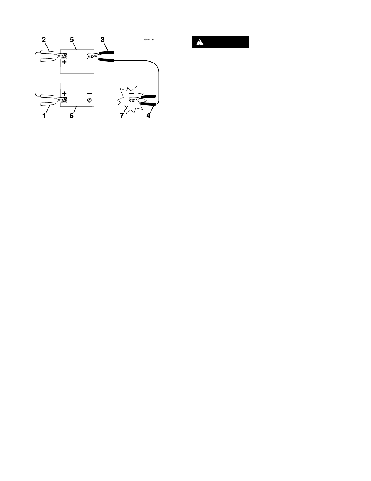
2.Makesuretheboosterisagoodandfullycharged
leadacidbatteryat12.6voltsorgreater.Use
properlysizedjumpercables(4to6AWG)with
3.Connectthepositive(+)cabletothepositive(+)
terminalofthedischargedbatterythatiswiredto
thestarterorsolenoidasshowninFigure16.
27
Page 28
Maintenance
CAUTION
Raisingtheunitforserviceormaintenance
relyingsolelyonmechanicalorhydraulic
jackscouldbedangerous.Themechanicalor
hydraulicjacksmaynotbeenoughsupport
ormaymalfunctionallowingtheunittofall,
whichcouldcauseinjury.
DoNotrelysolelyonmechanicalorhydraulic
g012785
Figure16
jacksforsupport.Useadequatejackstands
orequivalentsupport.
1.Positive(+)cableondischargedbattery
2.Positive(+)cableonboosterbattery
3.Negative(–)cableontheboosterbattery
4.Negative(–)cableontheengineblock
5.Boosterbattery
6.Dischargedbattery
7.Engineblock
4.Connecttheotherendofthepositivecabletothe
positiveterminaloftheboosterbattery.
5.Connecttheblacknegative(–)cabletotheother
terminal(negative)oftheboosterbattery.
6.MAKETHEFINALCONNECTIONON
THEENGINEBLOCKOFTHESTALLED
VEHICLE(NOTTOTHENEGATIVEPOST)
AWAYFROMTHEBATTERY .STANDBACK.
7.Startthevehicleandremovethecablesinthe
reverseorderofconnection(theengineblock
(black)connectionisthersttodisconnect).
3.Removeandretainthetwoboltsfromtherear
coverpanel.
4.Removerocksandotherdebrisfromthetines.
5.Inspectthetinesandreplaceasrequired.
CheckTines
ServiceInterval:Beforeeachuseordaily
1.Stopengine,waitforallmovingpartstostop,and
removekey.Engageparkingbrake.
2.Lifttherearoftheunitandsupportusingjack
standsorequivalentsupport.
28
Page 29
Maintenance
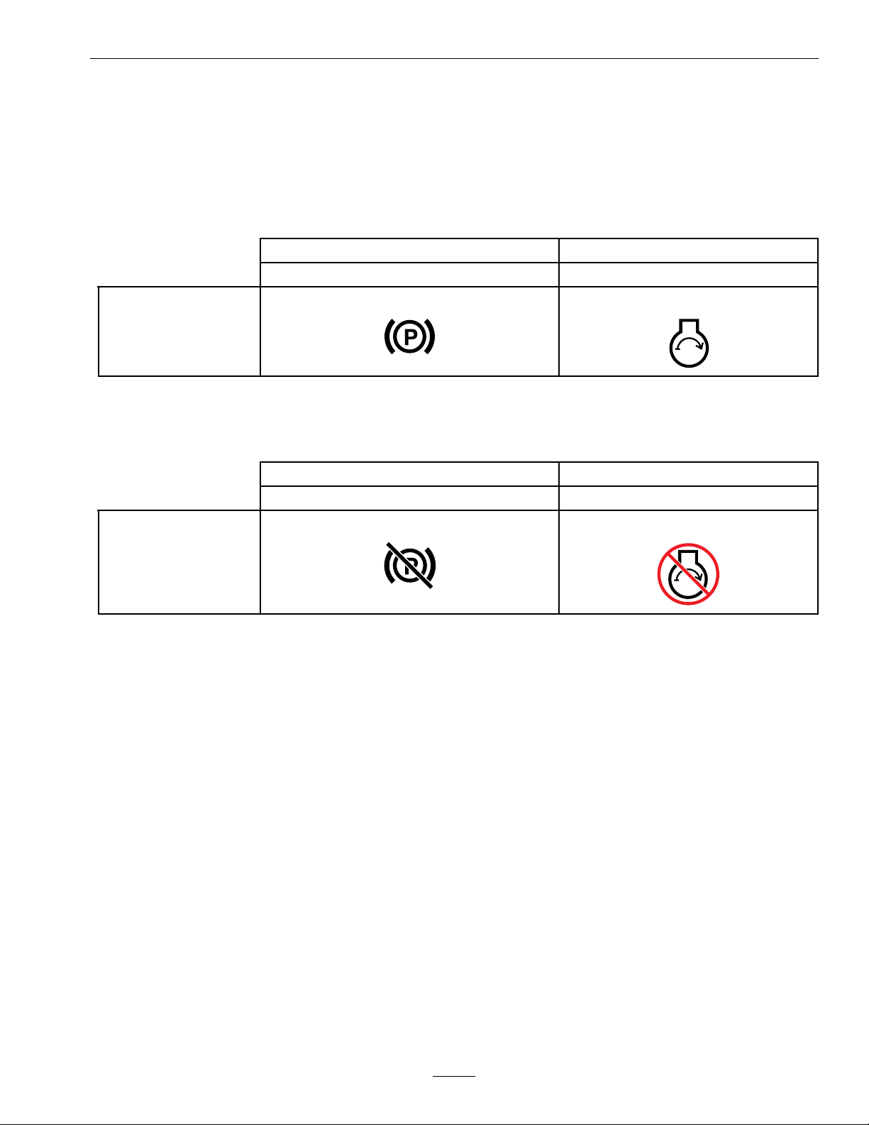
ChecktheSafetyInterlock
Important:Itisessentialthattheoperatorsafetymechanismsbeconnectedandinproperoperating
conditionpriortouse.
Note:Ifmachinedoesnotpassanyofthesetests,DoNotoperate.ContactanAuthorizedServiceDealer.
ChecktheNormalEngineStartingCircuit
System
ParkingBrakeOutcome
EngagedStartershouldcrank
StateofSystem
CheckEngineStartingCircuitChart
Note:IntheCheckEngineStartingCircuitChart,thestateofsystemitemthatisboldisbeingchecked.
System
ParkingBrakeOutcome
Disengaged
StateofSystem
Startershouldnotcrank
29
Page 30

Maintenance
CheckforLooseHardware
ServiceInterval:Beforeeachuseordaily
1.Stopengine,waitforallmovingpartstostop,and
removekey.Engageparkingbrake.
2.Visuallyinspectmachineforanyloosehardware
oranyotherpossibleproblem.Tightenhardware
orcorrecttheproblembeforeoperating.
ServiceAirCleaner
ServiceInterval:Every250hours—Replace
theprimaryaircleaner
element—check
secondaryaircleaner
element;replaceifdirty.
(Mayneedmoreoften
undersevereconditions.
SeetheEnginemanualfor
additionalinformation.)
Every500hours—
Replacethesecondary
aircleanerelement.(May
needmoreoftenunder
severeconditions.See
theEnginemanualfor
additionalinformation.)
1.Stopengine,waitforallmovingpartstostop,and
removekey.Engageparkingbrake.
2.SeetheEngineOwner'sManualformaintenance
instructions.
ChangeEngineOil
ServiceInterval:Aftertherst5hours
Every100hours(May
needmoreoftenunder
severeconditions.)
1.Stopengine,waitforallmovingpartstostop,and
removekey.Engageparkingbrake.
2.Drainoilwhileengineiswarmfromoperation.
3.Theoildrainplugislocatedontheleftsideof
theengine.
Placepanundermachinetocatchoil.Removeoil
drainplug.Allowoiltodrainandreplaceoildrain
plug.Torqueplugto13ft-lb(18N-m).
4.ReplacetheoillterpertheEngineOwner's
Manual.Cleanaroundtheoillterandcarefully
removethelterbyunscrewingit.Makesureno
oildrainsontothebeltdrivesthroughtheholesin
theenginedeck.Beforethenewlterisinstalled,
applyathincoatingofExmark4–CyclePremium
EngineOilonthesurfaceoftherubberseal.
Turnlterclockwiseuntilrubbersealcontacts
thelteradapter,thentightenlteranadditional
2/3to3/4turn.
5.Cleanaroundoilllcapandremovecap.Fillto
speciedcapacityandreplacecap.
6.UseoilrecommendedintheCheckEngineOil
Levelsection.DoNotoverll.Starttheengine
andcheckforleaks.Stopengineandrecheckoil
level.
7.Wipeupanyspilledoilfromenginedeck
mountingsurfaces.
CheckAuxiliaryHydraulic
OilLevel
ServiceInterval:Every50hours
1.Stopengineandwaitforallmovingpartstostop,
andremovekey.Engageparkingbrake.
2.Cleanareaaroundhydraulicreservoircapand
removecap.Oillevelshouldbetothetopofthe
bafeinsidethetank.Ifnot,addoil.UseAW -32
hydrooil.Replacehydraulicreservoircapand
tightenuntilsnug.DoNotovertighten.
Note:Thebafeislabeled“HOT”and
“COLD”.Theoillevelvarieswiththe
temperatureoftheoil.The“HOT”levelshows
thelevelofoilwhenitisat225°F(107°C).The
“COLD”levelshowstheleveloftheoilwhen
itisat75°F(24°C).Filltotheappropriatelevel
dependinguponthetemperatureoftheoil.For
example:Iftheoilisabout150°F(65°C),llto
halfwaybetweenthe“HOT”and“COLD”levels.
Iftheoilisatroomtemperature(about75°F
(24°C)),llonlytothe“COLD”level.
CheckHydraulic
TransmissionOilLevel
ServiceInterval:Every50hours
1.Stopengineandwaitforallmovingpartstostop,
andremovekey.Engageparkingbrake.
2.Withtheunitcold,checktheexpansiontankand
ifnecessaryaddExmarkPremiumHydroOilto
theFULLCOLDline.
30
Page 31

Maintenance
CheckTirePressures
ServiceInterval:Every50hours
1.Stopengine,waitforallmovingpartstostop,and
removekey.Engageparkingbrake.
2.Checktirepressureindrivetires.
3.Inatedrivetiresto22-24psi(152-165kPa).
4.Semi-pneumaticcastertiresdonotneedtobe
inated.
CheckConditionandTension
OfBelts
ServiceInterval:Every50hours
1.Stopengine,waitforallmovingpartstostop,and
removekey.Engageparkingbrake.
2.Checktheauxiliarypumpdrivebeltconditionand
tension;beltshouldbesnug.SeeAuxiliaryPump
DriveBeltAdjustmentintheAdjustments
section.
3.Checkconditionofthetransmissiondrivebelt.
1.Shutofftheengine,waitforallmovingpartsto
stop,andremovethekey.Engagetheparking
brake.
2.Lifttherearofthemachineandsupportusing
jackstandsorequivalentsupport.
CAUTION
Raisingthemachineforserviceor
maintenancerelyingsolelyonmechanical
orhydraulicjackscouldbedangerous.The
mechanicalorhydraulicjacksmaynotbe
enoughsupportormaymalfunctionallowing
themachinetofall,whichcouldcauseinjury.
Donotrelysolelyonmechanicalorhydraulic
jacksforsupport.Useadequatejackstands
orequivalentsupport.
3.Starttheengineandmovethrottlecontrolahead
to1/2throttleposition.Disengagetheparking
brake.
WARNING
CheckConditionOfChains
ServiceInterval:Beforeeachuseordaily
1.Stopengine,waitforallmovingpartstostop,and
removekey.Engageparkingbrake.
2.Checkthechainsonbothsidesoftheunitfor
propertension.Thechainsshouldbeableto
moveupanddown1/4-1/2inch(6-12mm).
3.IfchainspoporsnapseeDriveChain
TensionAdjustmentorTineDriveT ension
AdjustmentintheAdjustmentssection.
CheckConditionOf
Sprockets
ServiceInterval:Beforeeachuseordaily
1.Stopengine,waitforallmovingpartstostop,and
removekey.Engageparkingbrake.
2.Inspectsprocketsforwearandreplaceasrequired.
LubricatingtheChains
ServiceInterval:Beforeeachuseordaily
Important:Donotlubricatethechainswith
penetratingoilorsolvents.Useanoilorchain
lubricant.
Theenginemustberunningandthedrive
wheelsmustbeturningsothatadjustments
canbeperformed.Contactwithmovingparts
orhotsurfacesmaycausepersonalinjury.
Keepyourngers,hands,andclothingclear
ofrotatingcomponentsandhotsurfaces.
4.Withtheenginerunning,slowlymovethemotion
controlleversforwardandlubricateallfour
chains.
5.Checktheconditionandtensionofthechains
(seeCheckConditionofChains).
LubricatingtheGrease
Fittings
Note:Seethechartbelowforserviceintervals.
1.Shutofftheengine,waitforallmovingpartsto
stop,andremovethekey.Engagetheparking
brake.
2.LubricatethettingswithNLGIgradeNo.2
multi-purposegrease.
Refertothefollowingchartforttinglocations
andlubricationschedule.
LubricationChart
31
Page 32

Maintenance
LubricationChart(cont'd.)
Fitting
Locations
1.FrontWheel
CasterHubs
2.TineShaft
Bearings
3.BeltIdler
Pivot
Initial
Pumps
12
1
11
Numberof
Places
4
Service
Interval
Yearly
25hours
Yearly
Important:Applyathincoatofoilonthe
surfaceoftherubberseal.
Turnlterclockwiseuntilrubbersealcontactsthe
lteradapter,thentightenthelteranadditional
2/3to3/4turn.
5.Reinstallthehoseandtorqueto37ft-lb(50N-m).
6.AddA W-32hydrooiluntilthelevelreachesthe
“coldllline”locatedonthereservoirtank.Start
engineandraiseandlowerthetines.Lowerthe
tinestothegroundandrellthereservoirtothe
“coldllline”.
ChangeHydraulic
TransmissionFiltersand
Fluid
ServiceInterval:Aftertherst100hours
Every250hoursthereafter
1.Stopengine,waitforallmovingpartstostop,and
removekeyorsparkplugwire(s).Engageparking
brake.
CheckSparkPlug
ServiceInterval:Every160hours
Removethesparkplug,checkconditionandreset
gaps,orreplacewithanewplug.SeeEngineOwner's
Manual.
ChangeAuxiliaryHydraulic
ReservoirFluidandFilter
ServiceInterval:Aftertherst100hours
Every250hoursthereafter
1.Stopengine,waitforallmovingpartstostop,and
removekeyorsparkplugwire(s).Engageparking
brake.
2.Carefullycleanareaaroundthefrontofthe
auxiliarypumpandllcap;alsocleanaroundthe
lter.Itisimportantthatnodirtorcontamination
enterhydraulicsystem.
3.Unscrewthesuctionhosefromthepumptting,
cleanaroundthepumptting,andallowoilto
drain.
4.Unscrewtheltertoremoveandallowoilto
drain.
2.Placeacatchpanbetweenthetransmissions.
3.Removethetwodrainplugs,locatedatthebottom
ofeachtransmission,tofullydraintheoil.
4.Locatethetwoltersunderthetransmissions.
5.Carefullycleanareaaroundlters.Itisimportant
thatnodirtorcontaminationenterhydraulic
system.
6.Unscrewlterstoremoveandallowoiltonish
drainingfromdrivesystem.
Important:Beforereinstallingnewlters,
applyathincoatofExmarkPremiumHydro
Oilonthesurfaceoftheltersrubberseal.
Turntheltersclockwiseuntilrubberseal
contactsthelteradapterthentightenthelter
anadditional3/4to1fullturn.
7.Reinstallthetwodrainplugs.
8.Removetheventplugoneachtransmissionand
llthroughexpansionreservoir,whenoilcomes
outofventreinstallplug.
ExmarkPremiumHydroOilisrecommended.
Refertothechartforanacceptablealternative:
32
Page 33

Maintenance
HydroOil
ExmarkPremiumHydro
Oil(Preferred)
Mobil115W50
Torqueplugsto180in-lb(20N-m).Continueto
addExmarkPremiumHydroOiluntilitreaches
theFULLCOLDlineontheexpansionreservoir.
9.Raisetherearofmachineupandsupportwith
jackstands(orequivalentsupport)justhigh
enoughtoallowdrivewheelstoturnfreely.
ChangeInterval
250Hours
250Hours
CAUTION
Raisingtheunitforserviceormaintenance
relyingsolelyonmechanicalorhydraulic
jackscouldbedangerous.Themechanicalor
hydraulicjacksmaynotbeenoughsupport
ormaymalfunctionallowingtheunittofall,
whichcouldcauseinjury.
DoNotrelysolelyonmechanicalorhydraulic
jacksforsupport.Useadequatejackstands
orequivalentsupport.
Changingoilunnecessarilycoulddamagehydraulic
systembyintroducingcontaminantsintothesystem.
CheckTransmission
OutputShaftNutTorque
Specication
ServiceInterval:Aftertherst5hours
Yearlythereafter
Torquethenutonthetransmissionoutputtapered
shaftto211-260ft-lb(286-352N-m).
CheckWheelHubBolt
TorqueSpecication
ServiceInterval:Aftertherst5hours
Yearlythereafter
Torquethewheelhubboltto27-33ft-lb(37-45N-m).
Note:DoNotuseanti-seizecompoundonthe
wheelhub.
10.Startengineandmovethrottlecontrolaheadto
1/2throttleposition.Disengageparkingbrake.
WARNING
Enginemustberunninganddrivewheels
mustbeturningsomotioncontroladjustment
canbeperformed.Contactwithmovingparts
orhotsurfacesmaycausepersonalinjury.
Keepngers,hands,andclothingclearof
rotatingcomponentsandhotsurfaces.
A.Withtheenginerunning,slowlymovethe
directionalcontrolinbothforwardand
reversedirections(5to6times).Checktheoil
level,andaddoilasrequiredafterstopping
theengine.
B.ItmaybenecessarytorepeatstepA.untilall
theairiscompletelypurgedfromthesystem.
Whenthetransaxleoperatesatnormalnoise
levelsandmovessmoothlyforwardand
reverseatnormalspeeds,thenthetransaxle
isconsideredpurged.
Note:DoNotchangethehydraulicsystemoil
(exceptforwhatcanbedrainedwhenchanginglter
andremovingthedrainplugs),unlessitisfelttheoil
hasbeencontaminatedorbeenextremelyhot.
CheckTransmissionMount
BoltTorque
ServiceInterval:Aftertherst5hours
Yearlythereafter
Torquethefourtransmissionboltsto41-51ft-lb
(56-69N-m)(referenceFigure17).
Note:DoNotuseanti-seizecompoundonthe
wheelhub.
g233601
Figure17
1.Transmissionbolt
33
Page 34

Maintenance
CheckSparkArrester
(ifequipped)
ServiceInterval:Every50hours
WARNING
Hotexhaustsystemcomponentsmayignite
gasolinevaporsevenaftertheengineisstopped.
Hotparticlesexhaustedduringengineoperation
mayigniteammablematerials.Firemayresult
inpersonalinjuryorpropertydamage.
DoNotrefuelorrunengineunlesssparkarrester
isinstalled.
1.Stopengine,waitforallmovingpartstostop,and
removekey.Engageparkingbrake.
2.Waitformufertocool.
3.Ifanybreaksinthescreenorweldsareobserved,
replacearrester.
4.Ifpluggingofthescreenisobserved,remove
arresterandshakelooseparticlesoutofthe
arresterandcleanscreenwithawirebrush(soak
insolventifnecessary).Reinstallarresteron
exhaustoutlet.
ThreadLockingAdhesives
Threadlockingadhesivessuchas“Loctite242”
or“Fel-Pro,Pro-LockNutType”areusedonthe
followingfasteners:
Sheaveretainingboltinendofenginecrankshaft.
Allsetscrews.
34
Page 35

Maintenance
Adjustments
Note:Shutoffengine,waitforallmovingpartsto
stop,engageparkingbrake,andremovekeybefore
servicing,cleaning,ormakinganyadjustmentsto
theunit.
CAUTION
Raisingtheunitforserviceormaintenance
relyingsolelyonmechanicalorhydraulic
jackscouldbedangerous.Themechanicalor
hydraulicjacksmaynotbeenoughsupportor
maymalfunctionallowingtheunittofall,which
couldcauseinjury.
DoNotrelysolelyonmechanicalorhydraulic
jacksforsupport.Useadequatejackstandsor
equivalentsupport.
AuxiliaryPumpDriveBelt
Adjustment
1.Stopengine,waitforallmovingpartstostop,and
removekey.Engageparkingbrake.
2.Totightenbelt,loosenboth3/8inchnutson
auxiliarypump.Slidepumpoutwardinslotsand
retightennuts.
3.Whenproperlyadjusted,thebeltshouldhave1/2
inch(1.3cm)ofdeectionwiththreepoundsof
forceonthebeltmidwaybetweentheauxiliary
pumpandenginepulley .
3.Checkthechainsoneachsideoftheidler
sprocket,onbothsidesofthemachine,forproper
tension.Thechainsshouldbeabletomoveup
anddown1/4-1/2inch(6-12mm).
4.Toadjust,loosentheidlerboltandpushupon
thesprockettotensionthechain.
Note:DoNotovertightenthechain.
5.Recheckthechaintensionandtightentheidler
bolt.
TineDriveChainAdjustment
1.Stopengine,waitforallmovingpartstostop,and
removekey.Engageparkingbrake.
2.Lifttherearofthemachineandsupportusing
jackstandsorequivalentsupport.
3.Checkthechainsoneachsideoftheidler
sprocket,onbothsidesofthemachine,forproper
tension.Thechainsshouldbeabletomoveup
anddown1/4-1/2inch(6-12mm).
4.Toadjust,loosentheidlerboltandpushupon
thesprockettotensionthechain.
Note:DoNotovertightenthechain.
5.Recheckthechaintensionandtightentheidler
bolt.
AdjustingtheParkingBrake
TransmissionDriveBelt
Tension
Note:Noadjustmentsarerequiredforbelttension.
1.Stopengine,waitforallmovingpartstostop,and
removekey.Engageparkingbrake.
2.Installthenewbelt.
3.Makesuretheidlerarmandpulleycanmove
freely.
DriveWheelChainTension
Adjustment
1.Stopengine,waitforallmovingpartstostop,and
removekey.Engageparkingbrake.
2.Lifttherearofthemachineandsupportusing
jackstandsorequivalentsupport.
Iftheparkingbrakedoesnotholdsecurely ,an
adjustmentisrequired.
1.Parkthemachineonalevelsurface.
2.Shutoffengineandwaitforallmovingpartsto
stop.
3.Checktheairpressureinthedrivetires.Ifneeded,
adjusttotherecommendedination;referto
CheckTirePressuresection.
4.Disengagetheparkbrake.
5.Loosentheadjustmentnutonthebrakecable
bracketundertheconsole.
6.Adjustbothcableconduitsdownward
approximately1/8–1/4inch(3–6mm).See
Figure18.
35
Page 36
Maintenance
Figure18
1.Adjustmentnut
7.Tightenthecableadjustmentnutandengagethe
parkbrake.
8.Checktheparkbrake;repeatsteps5through7if
necessary.
MotionControlLinkage
Adjustment
1.Parkthemachineonalevelsurface.
2.Shutoffengineandwaitforallmovingpartsto
stop.
3.Pushthecontrolleversallthewayforwardtothe
frontreferencebar.
Ifeitherofthecontrolleverscontactthe
referencebar,allowthecontrolleverstoreturn
toneutral.Loosenthetwojamnutsonthe
RHhexadjustmentlinkage.Notethatone
jamnutisaright-handthreadandtheotheris
left-hand.Turnthehexadjustmentlinkageuntil
therecommendedgapisachieved.Retightenthe
jamnuts.Repeatthisstepuntilthereis1/8-1/4
inch(3–6mm)gapbetweentheRHcontrollever
andthefrontreferencebar.Oncethegapis
achieved,proceedwithstep4.
g233407
Figure19
1.Hexadjustmentlinkagejamnut
4.Allowthecontrolleverstoreturntoneutral.
TurntheLHhexadjustmentlinkuntilthemotion
controlleversareapproximatelyevenwitheach
other.
5.Repeatsteps3and4forothermotioncontrol
linkage.
MotionControlTracking
Adjustment
Ifthemachinetravelsorpullstoonesidewhenthe
motioncontrolleversareinthefullforwardposition,
adjustthetracking.
1.Pushbothcontrolleversforwardthesame
distance.
2.Checkifthemachinepullstooneside.Ifitdoes,
stopthemachineandsettheparkingbrake.
3.LoosenthelocknutsontheRHmotioncontrol
linkage(asviewedfromtherearofthemachine.
PushtheRHcontrolleverforwardandrotatethe
adjustmentroduntilthereis1/8-1/4inch(3–6
mm)gapbetweentheRHcontrolleverandthe
frontreferencebar.
4.SeeAdjustingtheFrontReference/Speed
ControlBarinOperation.Placethefront
reference/speedcontrolbarinthemaximum
forwardposition.
g231567
5.RotatetheadjustmentrodontheLHsideofthe
machine(asviewedfromtherearofthemachine
—seeFigure20).
36
Page 37
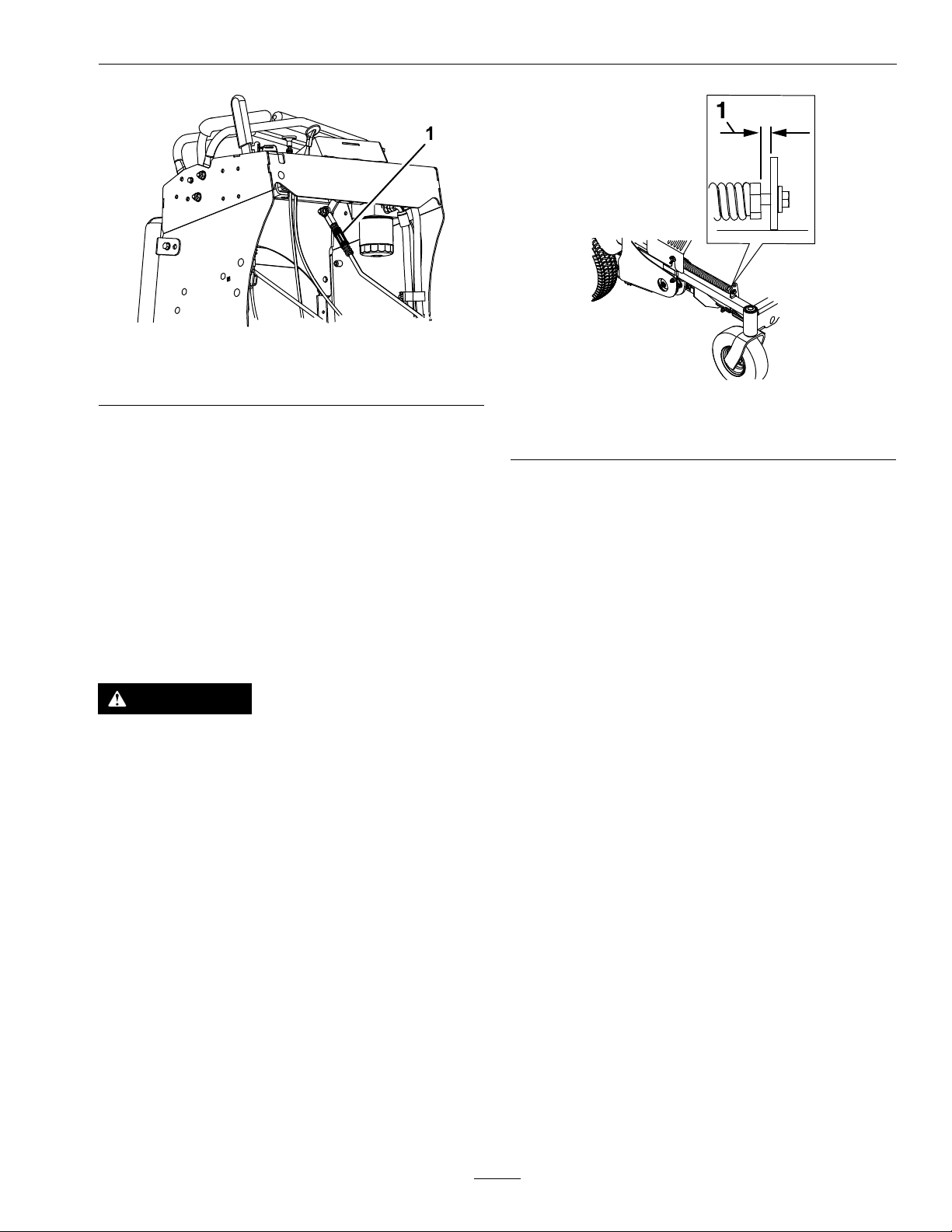
Figure20
Maintenance
g233418
1.Adjustmentrod
6.Lookingdowntowardstheadjustmentrod—
rotateitcounterclockwise,in1/4turnincrements,
toincreasespeedorclockwisetodecreasespeed.
7.Drivethemachineandcheckthefullforward
tracking.
8.Repeatsteps5through7untildesiredtracking
isobtained.
Return-to-UpSpring
Adjustment
WARNING
Springshavestoredenergy.Overtighteningthe
springsmaycausethespringstofailwhichcan
causeseriousinjuryordeathanddamagetothe
machineandproperty.
Makesurespringsareproperlyadjustedand/or
replacedasspeciedintheOperator'smanual.
g233568
Figure21
1.1.38inch(35mm)
Important:Thespringsmustbereplaceditthe
gapislessthan1.13inches(29mm).
Alwaysreplacebothreturn-to-upsprings.This
preventsunevenloadingandpossibledamageto
themachine.
Checkthegapbetweenthespringbracketandthe
endofthespringasshowninFigure21.Thegap
shouldmeasure1.38inch(35mm).Adjustmentis
madebyturningtheboltatthefrontofeachspring
(clockwisewillshortenthegap,counter-clockwise
willlengthenthegap).
37
Page 38

Maintenance
Cleaning
CleanEngineandExhaust
SystemArea
ServiceInterval:Beforeeachuseordaily
(Mayberequiredmore
oftenindryordirty
conditions.)
CAUTION
Excessivedebrisaroundenginecoolingair
intakeandexhaustsystemareacancauseengine,
exhaustarea,andhydraulicsystemtooverheat
whichcancreatearehazard.
Cleanalldebrisfromengineandexhaustsystem
area.
1.Stopengine,waitforallmovingpartstostop,and
removekey.Engageparkingbrake.
2.Cleanalldebrisfromrotatingengineairintake
screen,aroundengineshrouding,andexhaust
systemarea.
3.Wipeupanyexcessivegreaseoroilaroundthe
engineandexhaustsystemarea.
guards,aroundthefueltank,aroundengineand
exhaustarea.
WasteDisposal
MotorOilDisposal
Engineoilandhydraulicoilarebothpollutantsto
theenvironment.Disposeofusedoilatacertied
recyclingcenteroraccordingtoyourstateandlocal
regulations.
BatteryDisposal
DANGER
Batteryelectrolytecontainssulfuricacid,which
ispoisonousandcancausesevereburns.
Swallowingelectrolytecanbefatalorifittouches
skincancausesevereburns.
•Wearsafetyglassestoshieldeyes,andrubber
glovestoprotectskinandclothingwhen
handlingelectrolyte.
•DoNotswallowelectrolyte.
•Intheeventofanaccident,ushwithwater
andcalladoctorimmediately .
RemoveEngineShroudsand
CleanCoolingFins
ServiceInterval:Every80hours
1.Stopengine,waitforallmovingpartstostop,and
removekey.Engageparkingbrake.
2.Removecoolingshroudsfromengineandclean
coolingns.Alsocleandust,dirt,andoilfrom
externalsurfacesofenginewhichcancause
impropercooling.
3.Makesurecoolingshroudsareproperlyreinstalled.
Operatingtheenginewithoutcoolingshroudswill
causeenginedamageduetooverheating.
CleanDebrisFromMachine
ServiceInterval:Beforeeachuseordaily
1.Stopengine,waitforallmovingpartstostop,and
removekey.Engageparkingbrake.
2.Cleanoffanyoil,debris,orgrassbuild-uponthe
machineandaeratordeck,especiallyunderchain
Federallawstatesthatbatteriesshouldnotbeplaced
inthegarbage.Managementanddisposalpractices
mustbewithinrelevantfederal,state,orlocallaws.
Ifabatteryisbeingreplacedoriftheunitcontaining
thebatteryisnolongeroperatingandisbeing
scrapped,takethebatterytoalocalcertiedrecycling
center.Ifnolocalrecyclingisavailablereturnthe
batterytoanycertiedbatteryreseller.
38
Page 39

Troubleshooting
Troubleshooting
Important:Itisessentialthatalloperatorsafetymechanismsbeconnectedandinproperoperating
conditionpriortouse.
Whenaproblemoccurs,donotoverlookthesimplecauses.Forexample:startingproblemscouldbecaused
byanemptyfueltank.
Thefollowingtablelistssomeofthecommoncausesoftrouble.DoNotattempttoserviceorreplacemajor
itemsoranyitemsthatcallforspecialtimingofadjustmentsprocedures(suchasvalves,governor,etc.).Have
thisworkdonebyyourEngineServiceDealer.
Note:WhendisconnectingelectricalconnectorsDoNotpullonthewirestoseparatetheconnectors.
ProblemPossibleCauseCorrectiveAction
Starterdoesnotcrank.
Enginewillnotstart,startshard,orfailsto
keeprunning
1.Brakeswitchnotoperatingproperly.
2.Batterydoesnothaveafullcharge.
3.Electricalconnectionsarecorroded,loose
orfaulty.
4.Fuseisblown.4.Replacetheblownfuse.
5.Relayorswitchisdefective.5.ContactanAuthorizedServiceDealer.
1.Fueltankisempty .1.Fillthefueltank.
2.Fuelshutoffvalveisclosed.
3.Thethrottleandchokearenotinthe
correctposition.
4.Ambienttemperatureistoolow.
5.Dirt,water,orstalefuelisinthefuel
system.
6.Aircleanerisdirty .
7.
Electricalconnectionsarecorroded,loose
orfaulty.
8.Relayorswitchisdefective.8.ContactanAuthorizedServiceDealer.
9.Faultysparkplug.
10.
Sparkplugwireisnotconnected.
1.Checkthebrakeswitchandreplaceas
necessary.
2.
Chargethebattery.SeeCheckBattery
ChargeandRecommendedJump
StartingProceduresectionsin
Maintenance.
3.Checktheelectricalconnectionsfor
goodcontact.Cleanconnectorterminals
thoroughlywithelectricalcontactcleaner,
applydielectricgreaseandreconnect.
2.Openthefuelshutoffvalve.
3.Besurethethrottlecontrolismidway
betweenthe“SLOW”and“F AST”
positions,andthechokeisinthe“ON”
positionforacoldengineorthe“OFF”
positionforawarmengine.
4.Placemachineintoawarmerenvironment
untilhydroandengineoilwarms.
5.ContactanAuthorizedServiceDealer.
6.Cleanorreplacetheaircleanerelement.
7.Checktheelectricalconnectionsfor
goodcontact.Cleanconnectorterminals
thoroughlywithelectricalcontactcleaner,
applydielectricgreaseandreconnect.
9.Clean,adjustorreplacesparkplug.
Checkthesparkplugwireconnection.
10.
Enginelosespower.
1.Engineloadisexcessive.1.Reducethegroundspeedoraeration
2.
Aircleanerisdirty.
3.Oillevelinthecrankcaseislow .
4.
Coolingnsandairpassagesforthe
engineareplugged.
5.Dirt,water,orstalefuelisinthefuel
system.
depth.
2.Cleanorreplacetheaircleanerelement.
3.Addoiltothecrankcase.
4.
Removetheobstructionsfromthe
coolingnsandairpassages.
5.ContactanAuthorizedServiceDealer.
39
Page 40

Troubleshooting
ProblemPossibleCauseCorrectiveAction
Engineoverheats.
Machinepullsleftorright(withleversfully
forward).
Machinedoesnotdrive.
Abnormalvibration.
Tinesdonotraise.
1.Engineloadisexcessive.1.Reducethegroundspeedoraeration
2.Oillevelinthecrankcaseislow .
3.Coolingnsandairpassagesforthe
engineareplugged.
1.Tirepressureindrivetiresnotcorrect.1.Adjusttirepressureinthedrivetires.
2.Trackingneedsadjustment.
1.Driveorpumpbeltisworn,looseor
broken.
2.Driveorpumpbeltisoffapulley.2.Changethebelt.
1.Tine(s)is/arebent.
2.Tinemountingboltisloose.2.Tightenthetinemountingbolt.
3.Enginemountingboltsareloose.3.Tightentheenginemountingbolts.
4.Looseenginepulleyoridlerpulley .
5.Enginepulleyisdamaged.5.ContactanAuthorizedServiceDealer.
6.Beltisdamaged.6.Installnewbelt.
7.Chainsarenotproperlytensioned.
1.Return-to-upspringsarenotproperly
adjusted.
2.Return-to-upspringsaredamaged.
3.Shortinharness.
depth.
2.Addoiltothecrankcase.
3.Removetheobstructionsfromthe
coolingnsandairpassages.
2.
SeeMotionControlLinkage
AdjustmentinAdjustmentssection.
1.Changethebelt.
1.Installnewtine(s).
4.Tightentheappropriatepulley.
7.
SeeDriveWheelChainTension
AdjustmentandTineDriveChain
AdjustmentinAdjustmentssection.
1.
SeeReturn-to-UpSpringsAdjustment
intheAdjustmentssection.
2.Replacesprings.
3.ContactanAuthorizedServiceDealer.
Tinesdonotengagetheground.
1.Electronicdepthcontrolissettooshallow .1.Increaseelectronicdepthcontrolsetting.
2.Tinedownpressuresettingistoolow .2.Increasetinedownpressure.
3.Harness/switchisdamaged.
4.Auxiliaryreservoirislowonoil.4.Addoiltoreservoir.
5.Parkbrakeisengaged.5.Disengagetheparkbrake.
6.Tinegroundengagementswitchislocked
out.
3.ContactanAuthorizedServiceDealer.
6.Unlocktinegroundengagementswitch.
40
Page 41

BT01
TERMINAL +
TERMINAL -
BATTERY
S
IGNITION SWITCH
SW01
RUN
START
B
OFF
I
A
P07
D
P07
C
A
B
FUSE BLOCK
1
34576
P06
8
9
10
11
12
2
DIS01
FUEL-HOUR METER
B+
NC
SEN A IN
SW PWR
KEY S
START SIG
FOOT
NC
NC
NC
PARK BRAKE
TINE DOWN OUT
TINE UP OUT
DOWN IN
SEN B IN
UP IN
GND-S/D
GND
CAN LO
CAN HI
P08
121420
512
9
10
18
17
P08
3
4
7
1611131519
6
8
SW03
BRAKE SWITCH
P11
2
P11
1
GREEN/BROWN
GREEN/GRAY
WHITE/TAN
WHITE/BLACK
BLUEBLUE
BLUE
RED/WHITE
WHITE/BLUE
WHITE/BLUE
F01 15A
ACC'Y
F02 20A
MAIN
STARTER RELAY
K03
30
85
86
87
ACC SIGNAL
ACC PWR
GND
CAP01
ACC'Y
P01
A
B
C
NC
CAN HI
CAN LO
PWR -SW
PWR - FUSED
GND
CAP02
SERVICE PORT
P09
12345
6
SP01
RED
RED
ORANGE/RED
ORANGE/RED
BLACK
BLACK
BLACK
BLACK
BLACK
BLACK
BLACK
BLACK
BLACK
BLACK
BLACK
SP02
RED
RED
SP03
RED/GREEN
SP04
ORANGE
ORANGE
BLUE/RED BLUE/RED
SP05
BLUE
BLUE/BLACK
BLUE/BLACK
RED/WHITE
BLACK
WHITE/BROWN
WHITE/BROWN
BLACK
BLACK
RED/WHITE
RED/WHITE
RED/GREEN
VIOLET/RED
VIOLET/RED
BLACK
BLACK
BLACK
VIOLET/BLACK
VIOLET/BLACK
GREEN
GREEN
YELLOW
YELLOW
BLACK
RED/WHITE
RED/WHITE
RED/WHITE
RED/WHITE
RED/WHITE
RED/WHITE
RED/WHITE
RED/WHITE
RED/GREEN
BLACK
YELLOW/WHITE
YELLOW/WHITE
RED/GREEN
RED/GREEN
RED/GREEN
RED/GREEN
RED/GREEN
RED/GREEN
RED/GREEN
RED
BLACK
BLUE/YELLOW
J01
1
J02
1
SW02
FOOT SWITCH
P10
2
P10
1
B+
DC
REG
START
MAG
ENGINE - KOHLER
ENG01
BLACK
ENG
GND
IGNITION
MODULES
FLYWHEEL
ALT
REG VIOLET
P05
1
J05
J03
J04
J06
P02
1
PWR
2
GND
3
CHANNEL A4CHANNEL B
S04
DOWN
(ON)-OFF-(ON)
UP
P12
13468
P12
2
5
7
Relief
Valve
Manifold Assembly
L02
P03
Sol A-
2
P04
Sol B-
2
P03
Sol A+
1
P04
Sol B+
1
QUADRATURE SENSOR
SEN01
Schematics
Schematics
ElectricalSchematic
41
g231578
Page 42
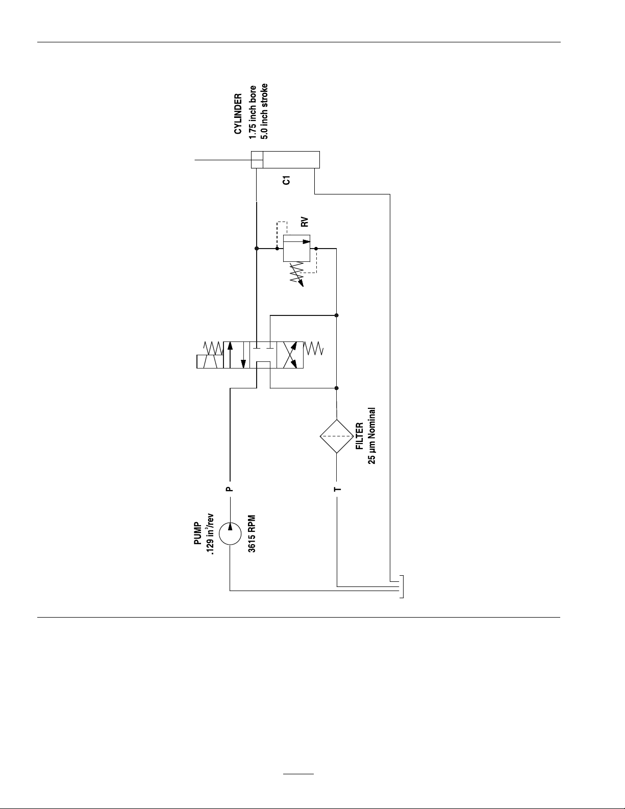
Schematics
HydraulicSchematic
g243786
42
Page 43

43
Page 44

MI D-MOUNT RIDING AC CESSORI ES AND OPTIONS
EXMARK ACCESSORIES AND OPTIONS*
WALK-BEHIND ACCESSORIES AND OPTIONS
GRASS CATCHER
MICRO-MULCH SYSTEM
TURF STRIPER
STANDON
CUSTOM RIDE SEAT SUSPENSION SYSTEM
FULL SUSPENSION SEAT
DECK LIFT ASSIST KIT
HITCH KIT
LIGHT KIT
12
V POWER PORT
MICRO-MULCH SYSTEM
OPERATOR CONTROLLED DISCHARGE
SUN SHADE
TRASH CONTAINER
TURF STRIPER
ULTRA VAC COLLECTION SYSTEM
ULTRA VAC QUICK DISPOSAL SYSTEM
OU T-FRONT RIDI NG ACCESS ORIES A ND OPTI ONS
CUSTOM RIDE SEAT SUSPENSION SYSTEM
DUAL-TAIL WHEEL
FLOOR PAN EXTENDER
HITCH KIT
LIGHT KIT
MICRO-MULCH SYSTEM
ROLL OVER PROTECTION SYSTEM (ROPS)
SNOW BLADE
SNOWBLOWER
SUN SHADE
TRASH CONTAINER
ULTRA VAC COLLECTION SYSTEM
ULTRA VAC QUICK DISPOSAL SYSTEM
WEATHER CAB
*Some accessories and options not available for some models.
PlaceModelNo.andSerialNo.
LabelHere(IncludedintheLiterature
ModelNo.EngineSerialNo.(E/No)
SerialNo.
Pack)orFillinBelow
DatePurchased
EngineModelNo.andSpec.No.
©2018ExmarkMfg.Co.,Inc.
2101AshlandAve
Beatrice,NE68310
AllRightsReserved
www.exmark.com
PartNo.4503-596Rev.B
(402)223-6375
Fax(402)223-5489
PrintedintheUSA
*4503-596*B
 Loading...