

Page 1

LAZERZ®HP
465,505,AND565MODELS
ForSerialNos.
720,000&Higher
PartNo.4500-251Rev.A
Page 2
WARNING
CALIFORNIA
Proposition65Warning
Theengineexhaustfromthisproduct
containschemicalsknowntotheStateof
Californiatocausecancer,birthdefects,or
otherreproductiveharm.
Important:Whenthemowerisusedoroperated
onanyCaliforniaforest,brushorgrasscovered
land,aworkingsparkarrestermustbeattached
tothemufer.Ifnot,theoperatorisviolating
statelaw,Section4442PublicResourceCode.To
acquireasparkarresterforyourunit,seeyour
EngineServiceDealer.
ThissparkignitionsystemcomplieswithCanadian
ICES-002Cesystèmed’allumageparètincellede
vèhiculeestconformeàlanormeNMB-002du
Canada
TheenclosedEngineOwner’sManualis
suppliedforinformationregardingTheU.S.
EnvironmentalProtectionAgency(EPA)and
theCaliforniaEmissionControlRegulationof
emissionsystems,maintenanceandwarranty.
KeepthisengineOwner’sManualwithyourunit.
ShouldthisengineOwner’sManualbecome
damagedorillegible,replaceimmediately.
Replacementsmaybeorderedthroughthe
enginemanufacturer.
Exmarkreservestherighttomakechangesor
addimprovementstoitsproductsatanytime
withoutincurringanyobligationtomakesuch
changestoproductsmanufacturedpreviously.
Exmark,oritsdistributorsanddealers,accept
noresponsibilityforvariationswhichmaybe
evidentintheactualspecicationsofitsproducts
andthestatementsanddescriptionscontained
inthispublication.
©1997–2007—ExmarkMfg.Co.,Inc.
IndustrialParkBox808
Beatrice,NE68310
Contactusatwww.Exmark.com.
2
PrintedintheUSA.
AllRightsReserved
Page 3
Introduction
CONGRATULATIONSonthepurchaseofyour
ExmarkMower.Thisproducthasbeencarefully
designedandmanufacturedtogiveyouamaximum
amountofdependabilityandyearsoftrouble-free
operation.
Thismanualcontainsoperating,maintenance,
adjustment,andsafetyinstructionsforyourExmark
mower.
BEFOREOPERATINGYOURMOWER,
CAREFULLYREADTHISMANUALINITS
ENTIRETY.
Byfollowingtheoperating,maintenance,andsafety
instructions,youwillprolongthelifeofyourmower,
maintainitsmaximumefciency,andpromotesafe
operation.
Ifadditionalinformationisneeded,orshouldyou
requiretrainedmechanicservice,contactyour
authorizedExmarkequipmentdealerordistributor.
AllExmarkequipmentdealersanddistributorsare
keptinformedofthelatestmethodsofservicing
andareequippedtoprovidepromptandefcient
serviceintheeldorattheirservicestations.They
carryamplestockofservicepartsorcansecurethem
promptlyforyoufromthefactory.
AllExmarkpartsarethoroughlytestedandinspected
beforeleavingthefactory,however,attentionis
requiredonyourpartifyouaretoobtainthefullest
measureofsatisfactionandperformance.
Wheneveryouneedservice,genuineExmarkparts,
oradditionalinformation,contactanAuthorized
ServiceDealerorExmarkCustomerServiceandhave
themodelandserialnumbersofyourproductready.
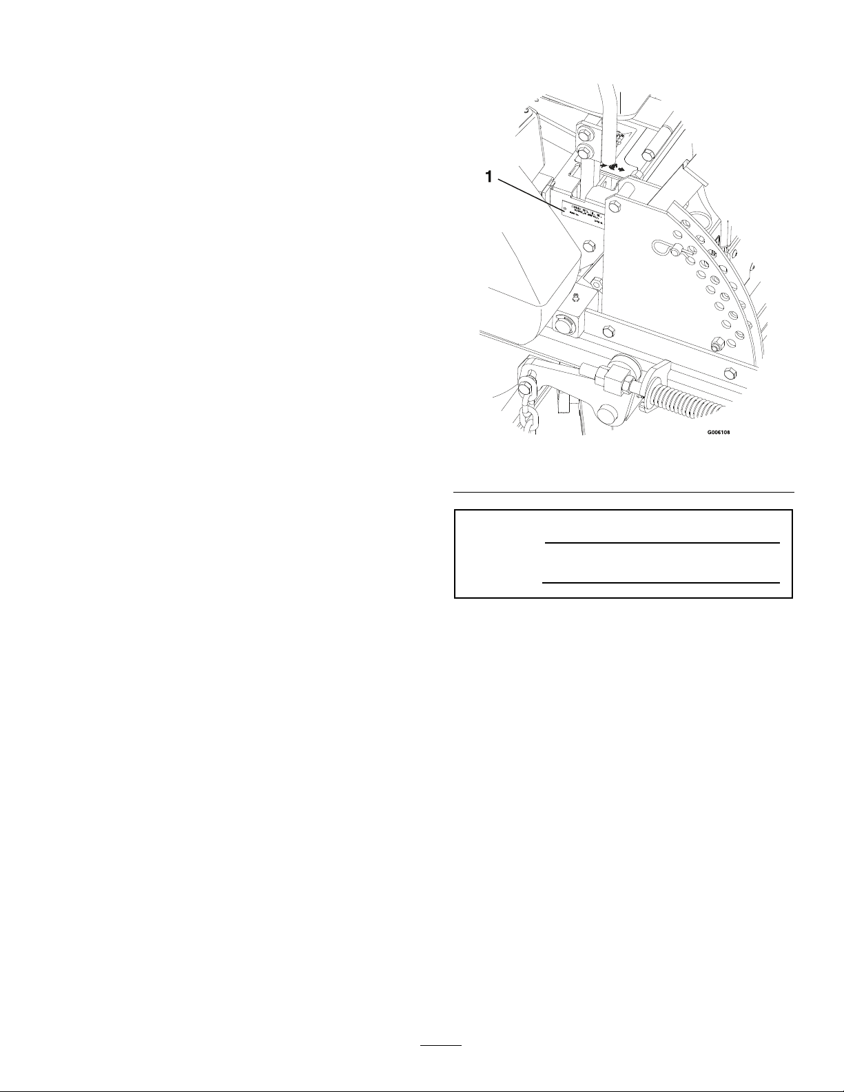
Figure1identiesthelocationofthemodelandserial
numbersontheproduct.Writethenumbersinthe
spaceprovided.
Figure1
1.Modelandserialnumberlocation
ModelNo.
SerialNo.
3
Page 4

Contents
Introduction...........................................................3
Safety.....................................................................5
SafetyAlertSymbol.........................................5
SafeOperatingPractices..................................5
SafetyandInstructionalDecals.....................10
Specications.......................................................14
ModelNumbers............................................14
Systems.........................................................14
Dimensions...................................................16
TorqueRequirements....................................17
ProductOverview................................................17
Operation.............................................................18
Controls........................................................18
Pre-Start........................................................19
OperatingInstructions..................................19
Transporting.................................................23
Maintenance.........................................................25
RecommendedMaintenanceSchedule(s)...........25
PeriodicMaintenance.......................................26
CheckEngineOilLevel.................................26
CheckBatteryCharge....................................26
CheckMowerBlades.....................................27
CheckSafetyInterlockSystem.......................27
CheckRolloverProtectionSystem(Roll
Bar)Pins...................................................28
CheckSeatBelt..............................................28
CheckforLooseHardware............................28
ServiceAirCleaner........................................28
ChangeEngineOil........................................28
CheckHydraulicOilLevel.............................29
CheckTirePressures.....................................29
CheckConditionOfBelts..............................29
LubricateGreaseFittings...............................29
LubricateCasterWheelHubs........................30
LubricateBrakeHandlePivot........................31
LubricateBrakeRodBushings.......................31
LubricateMotionControlBronze
Bushings...................................................31
LubricateSeatSwitchActuator......................31
CheckSparkPlugs.........................................31
ChangeHydraulicSystemFilter.....................31
WheelHub-SlottedNutTorque
Specication..............................................32
ThreadLockingAdhesives.............................32
MobilHTSGrease(OrFood-Grade
Anti-seize).................................................32
Copper-BasedAnti-seize..............................32
DielectricGrease...........................................32
Adjustments.....................................................33
DeckLeveling...............................................33
PumpDriveBeltTension...............................33
DeckBeltTension........................................33
BrakeLinkAdjustment..................................34
BrakeAdjustment..........................................34
ElectricClutchAdjustment............................34
ReverseIndicatorAdjustment........................34
MotionControlLinkageAdjustment.............35
AdjustSeatSwitch........................................36
CasterPivotBearingsPre-Load
Adjustment...............................................36
Cleaning...........................................................37
CleanEngineCoolingSystem........................37
RemoveEngineShroudsandCleanCooling
Fins...........................................................37
CleanGrassBuild-UpUnderDeck................37
WasteDisposal..............................................37
Troubleshooting...................................................39
Schematics...........................................................41
4
Page 5
Safety
Safety
SafetyAlertSymbol
ThisSafetyAlertSymbol(Figure2)isusedbothin
thismanualandonthemachinetoidentifyimportant
safetymessageswhichmustbefollowedtoavoid
accidents
Thissymbolmeans:ATTENTION!BECOME
ALERT!YOURSAFETYISINVOLVED!
Figure2
1.Safetyalertsymbol
Thesafetyalertsymbolappearsaboveinformation
whichalertsyoutounsafeactionsorsituations
andwillbefollowedbythewordDANGER,
WARNING,orCAUTION.
•Neverletchildrenoruntrainedpeopleoperate
orservicetheequipment.Localregulationsmay
restricttheageoftheoperator.
•Theowner/usercanpreventandisresponsible
foraccidentsorinjuriesoccurringtohimselfor
herself,otherpeopleorproperty.
Preparation
•Evaluatetheterraintodeterminewhataccessories
andattachmentsareneededtoproperlyand
safelyperformthejob.Onlyuseaccessoriesand
attachmentsapprovedbyExmark.
•Wearappropriateclothingincludingsafetyglasses,
substantialfootwear,longtrousers,andhearing
protection.DoNotoperatewhenbarefootor
whenwearingopensandals.Longhair,loose
clothingorjewelrymaygettangledinmoving
parts.
CAUTION
DANGER:Whitelettering/Redbackground.
Indicatesanimminentlyhazardoussituationwhich,if
notavoided,Willresultindeathorseriousinjury.
WARNING:Blacklettering/Orangebackground.
Indicatesapotentiallyhazardoussituationwhich,if
notavoided,Couldresultindeathorseriousinjury.
CAUTION:Blacklettering/Y ellowbackground.
Indicatesapotentiallyhazardoussituationwhich,if
notavoided,Mayresultinminorormoderateinjury.
Thismanualusestwootherwordstohighlight
information.Importantcallsattentiontospecial
mechanicalinformationandNoteemphasizes
generalinformationworthyofspecialattention.
SafeOperatingPractices
Training
•ReadtheOperator’sManualandothertraining
material.Iftheoperator(s)ormechanic(s)can
notreadEnglishitistheowner’sresponsibilityto
explainthismaterialtothem.
Thismachineproducessoundlevelsin
excessof85dBAattheoperator’searand
cancausehearinglossthroughextended
periodsofexposure.
Wearhearingprotectionwhenoperatingthis
machine.
•Inspecttheareawheretheequipmentistobe
usedandremoveallrocks,toys,sticks,wires,
bones,andotherforeignobjectswhichcanbe
thrownbythemachineandmaycausepersonal
injurytotheoperatororbystanders.
•Becomefamiliarwiththesafeoperationofthe
equipment,operatorcontrols,andsafetysigns.
•Alloperatorsandmechanicsshouldbetrained.
Theownerisresponsiblefortrainingtheusers.
5
Page 6
Safety
DANGER
Incertainconditionsgasolineisextremely
ammableandvaporsareexplosive.
Areorexplosionfromgasolinecanburn
you,others,andcausepropertydamage.
•Fillthefueltankoutdoorsinanopen
area,whentheengineiscold.Wipeup
anygasolinethatspills.
•Neverrellthefueltankordrainthe
machineindoorsorinsideanenclosed
trailer.
•DoNotllthefueltankcompletely
full.Addgasolinetothefueltankuntil
thelevelis1/4to1/2inch(6–13mm)
belowthebottomofthellerneck.This
emptyspaceinthetankallowsgasoline
toexpand.
•Neversmokewhenhandlinggasoline,
andstayawayfromanopenameor
wheregasolinefumesmaybeignitedby
spark.
•Storegasolineinanapprovedcontainer
andkeepitoutofthereachofchildren.
•Addfuelbeforestartingtheengine.
Neverremovethecapofthefueltankor
addfuelwhenengineisrunningorwhen
theengineishot.
•Iffuelisspilled,DoNotattempttostart
theengine.Moveawayfromtheareaof
thespillandavoidcreatinganysourceof
ignitionuntilfuelvaporshavedissipated.
•DoNotoperatewithoutentireexhaust
systeminplaceandinproperworking
condition.
DANGER
Incertainconditionsduringfueling,static
electricitycanbereleasedcausingaspark
whichcanignitegasolinevapors.Areor
explosionfromgasolinecanburnyouand
othersandcausepropertydamage.
•Alwaysplacegasolinecontainersonthe
groundawayfromyourvehiclebefore
lling.
•DoNotllgasolinecontainersinsidea
vehicleoronatruckortrailerbedbecause
interiorcarpetsorplastictruckbedliners
mayinsulatethecontainerandslowthe
lossofanystaticcharge.
•Whenpractical,removegas-powered
equipmentfromthetruckortrailerand
refueltheequipmentwithitswheelson
theground.
•Ifthisisnotpossible,thenrefuelsuch
equipmentonatruckortrailerfroma
portablecontainer,ratherthanfroma
gasolinedispensernozzle.
•Ifagasolinedispensernozzlemustbe
used,keepthenozzleincontactwiththe
rimofthefueltankorcontaineropening
atalltimesuntilfuelingiscomplete.
WARNING
Gasolineisharmfulorfatalifswallowed.
Long-termexposuretovaporshascaused
cancerinlaboratoryanimals.Failuretouse
cautionmaycauseseriousinjuryorillness.
•Avoidprolongedbreathingofvapors.
•Keepfaceawayfromnozzleandgas
tank/containeropening.
•Keepawayfromeyesandskin.
•Neversiphonbymouth.
•Checkthattheoperator’spresencecontrols,
safetyswitches,andshieldsareattachedand
functioningproperly .DoNotoperateunlessthey
arefunctioningproperly.
6
Page 7

Safety
Operation
WARNING
Operatingengineparts,especiallythe
mufer,becomeextremelyhot.Severeburns
canoccuroncontactanddebris,suchas
leaves,grass,brush,etc.cancatchre.
•Allowengineparts,especiallythemufer,
tocoolbeforetouching.
•Removeaccumulateddebrisfrommufer
andenginearea.
•Installandmaintaininworkingordera
sparkarresterbeforeusingequipment
onforest-covered,grass-covered,or
brush-coveredunimprovedland.
WARNING
Engineexhaustcontainscarbonmonoxide,
whichisanodorlessdeadlypoisonthatcan
killyou.
DoNotrunengineindoorsorinasmall
connedareawheredangerouscarbon
monoxidefumescancollect.
•Operateonlyindaylightorgoodarticiallight,
keepingawayfromholesandhiddenhazards.
•Besurealldrivesareinneutralandparkingbrake
isengagedbeforestartingengine.Useseatbelts.
•Neveroperatethemowerwithdamagedguards,
shields,orcovers.Alwayshavesafetyshields,
guards,switchesandotherdevicesinplaceandin
properworkingcondition.
•Nevermowwiththedischargedeectorraised,
removedoralteredunlessthereisagrass
collectionsystemormulchkitinplaceand
workingproperly .
•DoNotchangetheenginegovernorsettingor
overspeedtheengine.
•Stopengine,waitforallmovingpartstostop,
removekeyandengageparkingbrake:
–Beforechecking,cleaningorworkingonthe
mower.
–Afterstrikingaforeignobjectorabnormal
vibrationoccurs(inspectthemowerfor
damageandmakerepairsbeforerestarting
andoperatingthemower).
–Beforeclearingblockages.
–Wheneveryouleavethemower.
•Stopengine,waitforallmovingpartstostop,and
engageparkingbrake:
–Beforerefueling.
–Beforedumpingthegrasscatcher.
WARNING
Hands,feet,hair,clothing,oraccessoriescan
becomeentangledinrotatingparts.Contact
withtherotatingpartscancausetraumatic
amputationorseverelacerations.
•DoNotoperatethemachinewithout
guards,shields,andsafetydevicesin
placeandworkingproperly.
•Keephands,feet,hair,jewelry ,orclothing
awayfromrotatingparts.
•NEVERcarrypassengers.DONOToperate
themowerwhenpeople,especiallychildren,or
petsareinthearea.
•Bealert,slowdownandusecautionwhenmaking
turns.Lookbehindandtothesidebefore
changingdirections.
•Stoptheblades,slowdown,andusecautionwhen
crossingsurfacesotherthangrassandwhen
transportingthemowertoandfromtheareato
bemowed.
•Beawareofthemowerdischargepathanddirect
dischargeawayfromothers.
•DoNotoperatethemowerundertheinuence
ofalcoholordrugs.
•Useextremecarewhenloadingorunloadingthe
machineintoatrailerortruck.
•Usecarewhenapproachingblindcorners,shrubs,
trees,orotherobjectsthatmayobscurevision.
SlopeOperation
UseExtremecautionwhenmowingand/orturning
onslopesaslossoftractionand/ortip-overcould
occur.Theoperatorisresponsibleforsafeoperation
onslopes.
7
Page 8
Safety
DANGER
Operatingonwetgrassorsteepslopescan
causeslidingandlossofcontrol.Wheels
droppingoveredges,ditches,steepbanks,or
watercancauserollovers,whichmayresult
inseriousinjury,deathordrowning.
•DoNotmowslopeswhengrassiswet.
•DoNotmowneardrop-offsornearwater.
•DoNotmowslopesgreaterthan15
degrees.
•Reducespeedanduseextremecaution
onslopes.
•Avoidsuddenturnsorrapidspeed
changes.
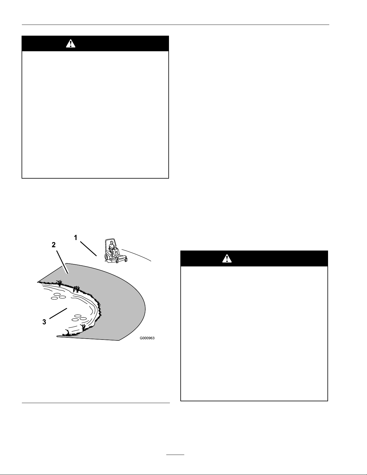
•Seeinsidethebackcovertodeterminethe
approximateslopeangleoftheareatobemowed.
•Useawalkbehindmowerand/orahandtrimmer
neardrop-offs,ditches,steepbanksorwater.
(Figure3).
•Watchforditches,holes,rocks,dipsandrisesthat
changetheoperatingangle,asroughterraincould
overturnthemachine.
•Avoidsuddenstartswhenmowinguphillbecause
themowermaytipbackwards.
•Beawarethatlossoftractionmayoccurgoing
downhill.Weighttransfertothefrontwheels
maycausedrivewheelstoslipandcauselossof
brakingandsteering.
•Alwaysavoidsuddenstartingorstoppingona
slope.Iftireslosetraction,disengagetheblades
andproceedslowlyofftheslope.
•Followthemanufacturer’srecommendationsfor
wheelweightsorcounterweightstoimprove
stability.
•Useextremecarewithgrasscatchersor
attachments.Thesecanchangethestabilityofthe
machineandcauselossofcontrol.
UsingtheRolloverProtectionSystem
(ROPS)
ARolloverProtectionSystem(rollbar)isinstalled
ontheunit.
Figure3
1.SafeZone-Usethe
mowerhereonslopes
lessthan15degrees
2.DangerZone-Useawalk
behindmowerand/or
handtrimmernear
drop-offsandwater.
3.Water
•Removeormarkobstaclessuchasrocks,tree
limbs,etc.fromthemowingarea.Tallgrasscan
hideobstacles.
WARNING
Thereisnorolloverprotectionwhentheroll
barisdown.Wheelsdroppingoveredges,
ditches,steepbanks,orwatercancause
rollovers,whichmayresultinseriousinjury,
deathordrowning.
•Keeptherollbarintheraisedandlocked
positionanduseseatbelt.
•Lowertherollbaronlywhenabsolutely
necessary.
•DoNotwearseatbeltwhentherollbar
isdown.
•Driveslowlyandcarefully.
•Raisetherollbarassoonasclearance
permits.
•Checkcarefullyforoverheadclearances(i.e.
branches,doorways,andelectricalwires)before
drivingunderanyobjectsanddonotcontactthem.
8
Page 9

Safety
MaintenanceandStorage
•Disengagedrives,lowerimplement,setparking
brake,stopengineandremovekeyordisconnect
sparkplugwire.W aitforallmovementtostop
beforeadjusting,cleaningorrepairing.
•Keepengine,enginearea,andpumpdrivebelt
compartmentfreefromaccumulationofgrass,
leaves,excessivegreaseoroil,andotherdebris
whichcanaccumulateintheseareas.These
materialscanbecomecombustibleandmayresult
inare.
•Letenginecoolbeforestoringanddonotstore
nearameoranyenclosedareawhereopenpilot
lightsorheatappliancesarepresent.
•Shutofffuelwhilestoringortransporting.Do
Notstorefuelnearamesordrainindoors.
•Parkmachineonlevelground.Neverallow
untrainedpersonneltoservicemachine.
•Usejackstandstosupportcomponentswhen
required.
•Carefullyreleasepressurefromcomponentswith
storedenergy.
•Disconnectbatteryorremovesparkplugwire
beforemakinganyrepairs.Disconnectthe
negativeterminalrstandthepositivelast.
Reconnectpositiverstandnegativelast.
WARNING
Hydraulicuidescapingunderpressure
canpenetrateskinandcauseinjury.Fluid
accidentallyinjectedintotheskinmustbe
surgicallyremovedwithinafewhoursbya
doctorfamiliarwiththisformofinjuryor
gangrenemayresult.
•Makesureallhydraulicuidhoses
andlinesareingoodconditionand
allhydraulicconnectionsandttings
aretightbeforeapplyingpressureto
hydraulicsystem.
•Keepbodyandhandsawayfrompinhole
leaksornozzlesthatejecthighpressure
hydraulicuid.
•Usecardboardorpaper,notyourhands,
tondhydraulicleaks.
•Safelyrelieveallpressureinthehydraulic
systembyplacingthemotioncontrol
leversinneutralandshuttingoffthe
enginebeforeperforminganyworkon
thehydraulicsystem.
•Usecarewhencheckingblades.Wraptheblade(s)
orweargloves,andusecautionwhenservicing
them.Onlyreplaceblades.Neverstraightenor
weldthem.
•Keephandsandfeetawayfrommovingparts.
Ifpossible,donotmakeadjustmentswiththe
enginerunning.
•Chargebatteriesinanopenwellventilatedarea,
awayfromsparkandames.Unplugcharger
beforeconnectingordisconnectingfrombattery.
Wearprotectiveclothinganduseinsulatedtools.
•Keepallguards,shieldsandallsafetydevicesin
placeandinsafeworkingcondition.
•Checkallboltsfrequentlytomaintainproper
tightness.
•Frequentlycheckforwornordeteriorating
componentsthatcouldcreateahazard.
•Allreplacementpartsmustbethesameas
orequivalenttothepartssuppliedasoriginal
equipment.
9
Page 10
Safety
SafetyandInstructionalDecals
•Keepallsafetysignslegible.Removeallgrease,
dirtanddebrisfromsafetysignsandinstructional
labels.
•Replaceallworn,damaged,ormissingsafety
signs.
•Whenreplacementcomponentsareinstalled,be
surethatcurrentsafetysignsareafxedtothe
replacedcomponents.
•Ifanattachmentoraccessoryhasbeeninstalled,
makesurecurrentsafetysignsarevisible.
1-303508
•Newsafetysignsmaybeobtainedfrom
yourauthorizedExmarkequipmentdealeror
distributororfromExmarkMfg.Co.Inc.
•Safetysignsmaybeafxedbypeelingoffthe
backingtoexposetheadhesivesurface.Apply
onlytoaclean,drysurface.Smoothtoremove
anyairbubbles.
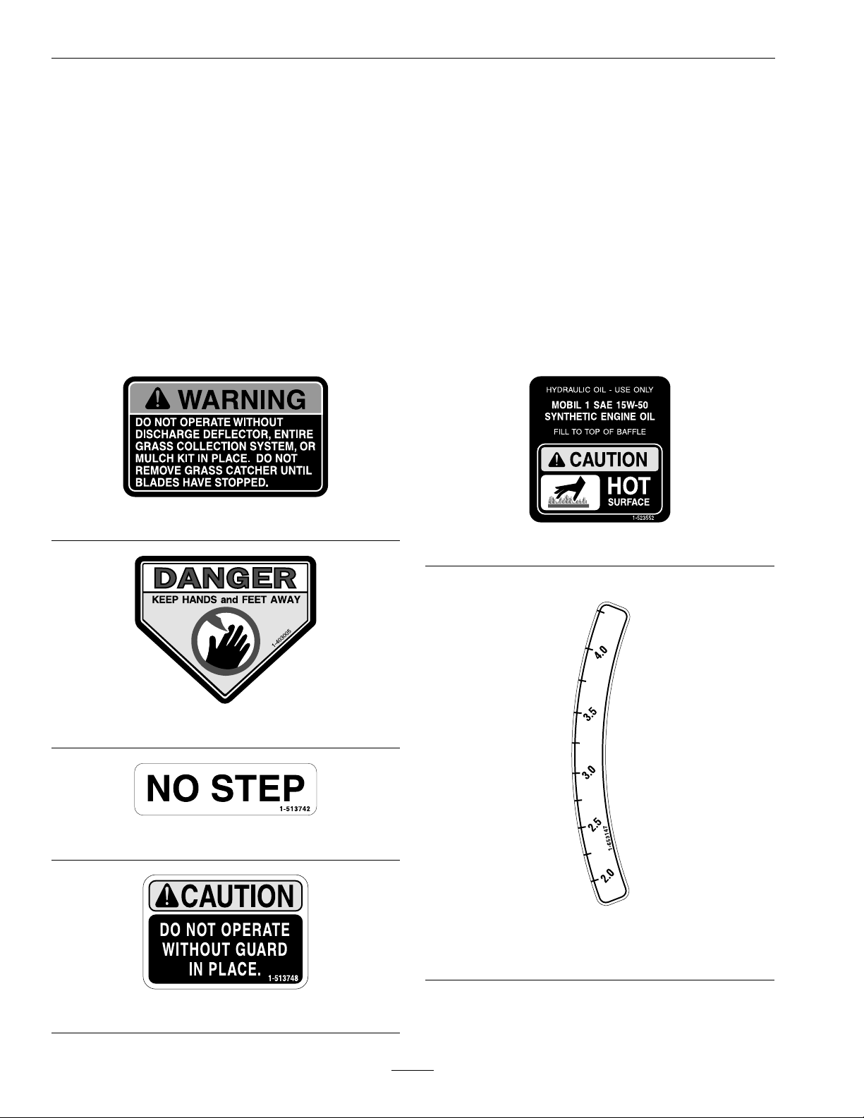
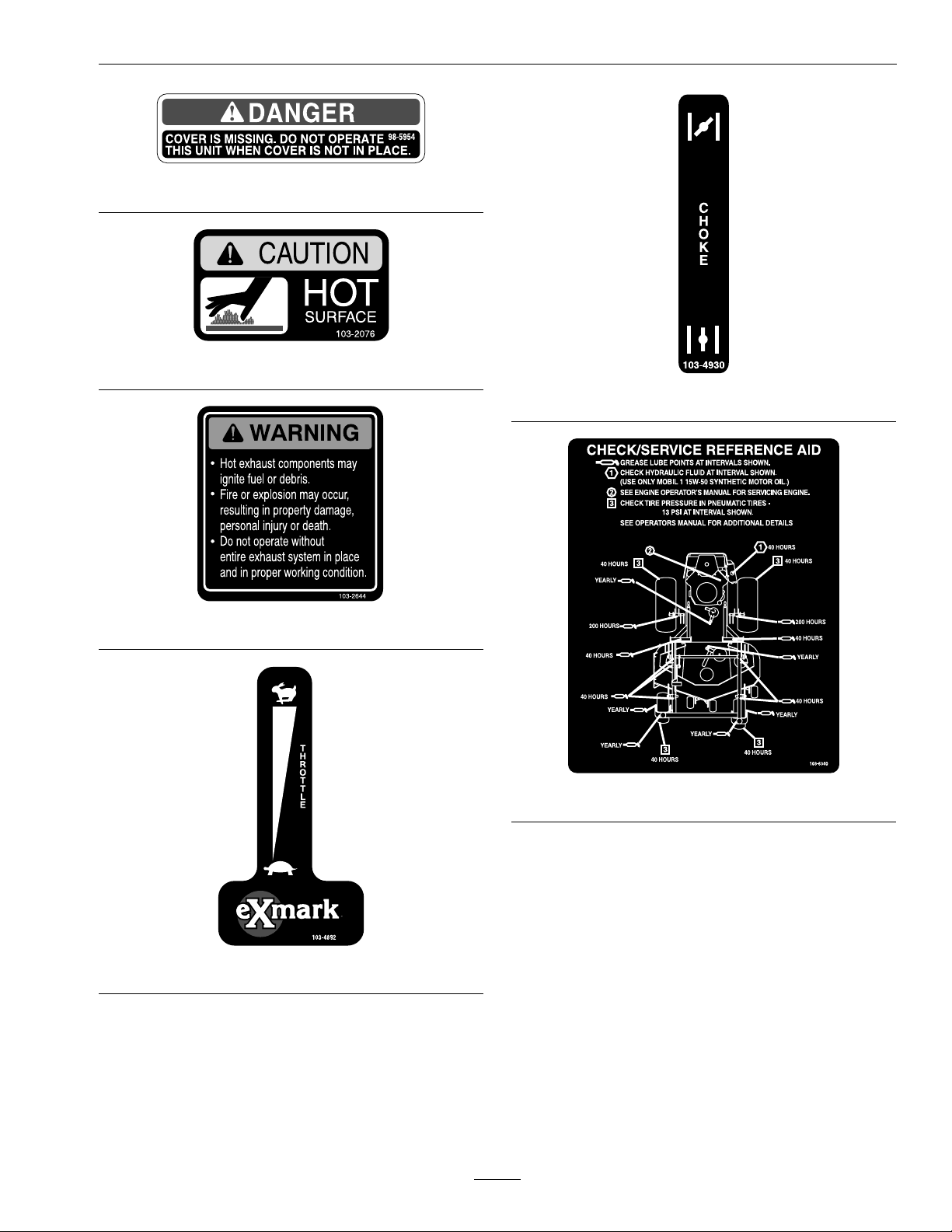
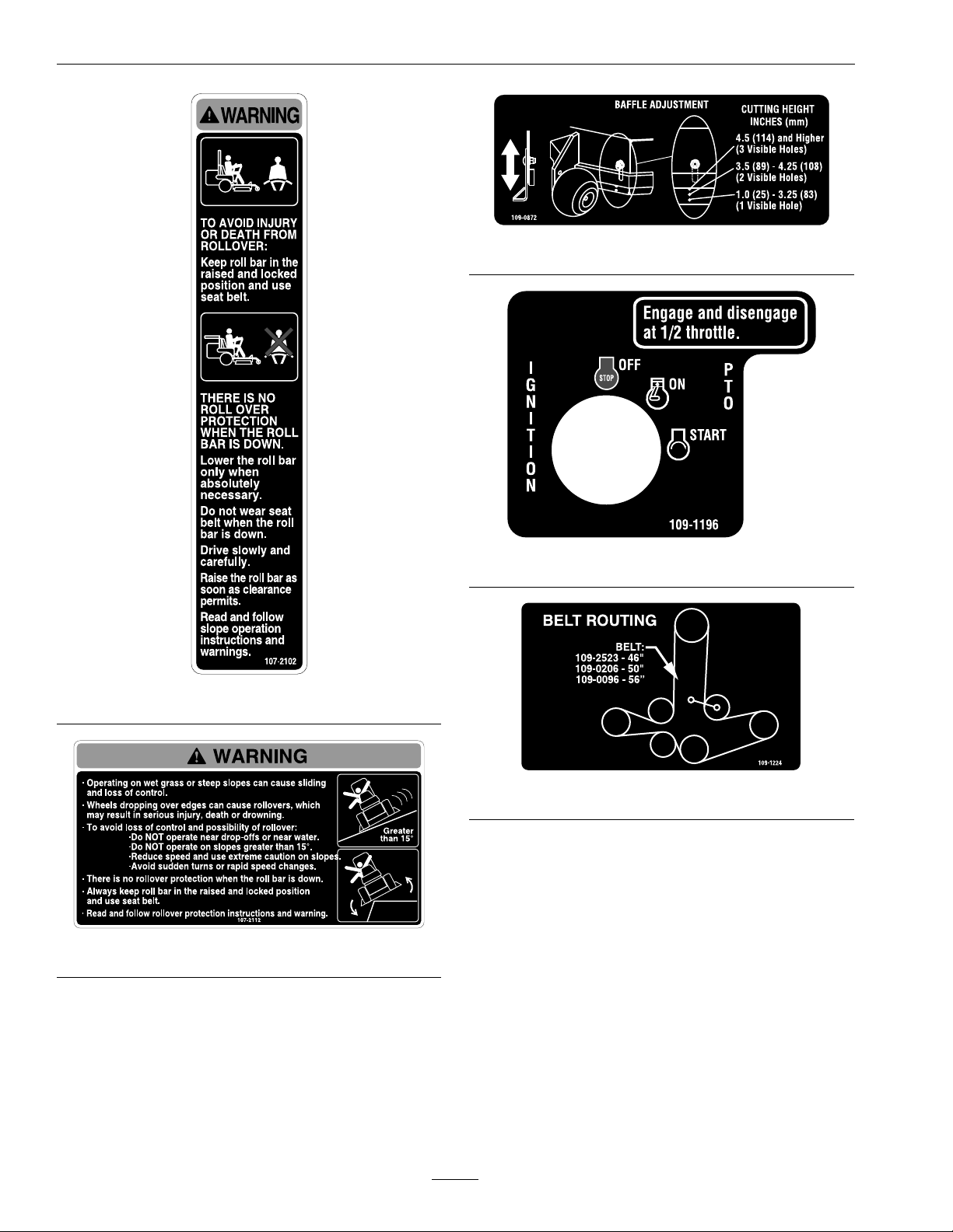
•Familiarizeyourselfwiththefollowingsafetysigns
andinstructionlabels.Theyarecriticaltothesafe
operationofyourExmarkcommercialmower.
1-523552
1-403005
1-513742
1–653147
1-513748
10
Page 11
Safety
98-5954
103–2076
103–4930
103–2644
103–6340
103–4892
11
Page 12
Safety
109-0872
107-2102
107-2112
109–1196
109–1224
12
Page 13

Safety
109-3148
109–7949
109–1399
103–4891
108–5995
1.Fast
2.Slow
3.Neutral4.Reverse
13
Page 14

Specications
Specications
ModelNumbers
SerialNos:720,000andHigher
LHP19KA465;LHP19KA465CA;LHP23KA465;LHP23KA505;LHP23KA565;LHP27KC505;LHP27KC505R;
LHP27KC565
Systems
Engine
•EngineSpecications:SeeyourEngineOwner’s
Manual
•RPM:FullSpeed:3600±50RPM(NoLoad)
Idle:1500RPM
FuelSystem
•Capacity:11.2gal.(42.0L)
•TypeofFuel:Regularunleadedgasoline,87
octaneorhigher.
•FuelFilter:
–Kohler:
In-line15MicronKohlerP/N2405010.
–Kawasaki:
In-lineKawasakiP/N49019–7001
•FuelShut-OffValve:1/4turnincrements(“ON”,
“OFF”)
•Fuelgaugeinlefthandfueltank.
•OperatormustbeinseatwhenPTOisengaged,
brakeisdisengaged,ormotioncontrolleversare
movedinorenginewillstop.
•Enginewillstopifeithertheleft,theright,or
bothleversaremovedfromneutrallockposition
whilebrakeisengaged.
OperatorControls
•SteeringandMotionControl:
Note:Motioncontrolleversareadjustableto
twoheights.
–Separatelevers,oneachsideoftheconsole,
controlspeedanddirectionoftravelofthe
respectivedrivewheels.
–Steeringiscontrolledbyvaryingtheposition
oftheleversrelativetoeachother.
–Movingmotioncontrolleversoutward(in
slots)locksthedrivesysteminneutral.
•PTOEngagementSwitch:Engageselectricclutch
(todrivebelt)whichengagesmowerblades.
•ParkingBrakeLever:Engagesparkingbrake.
ElectricalSystem
•ChargingSystem:FlywheelAlternator
•ChargingCapacity:15amps
•BatteryType:BCIGroupU1
•BatteryVoltage:12Volt
•Polarity:NegativeGround
•Fuses:Two20ampbladetype
SafetyInterlockSystem
•PTOmustbedisengaged,brakeengaged,and
motioncontrolleversout(neutrallock)tostart
engine.(Itisnotnecessaryfortheoperatortobe
intheseattostarttheengine.)
•DeckHeightAdjustmentLever:Setscutting
heighttodesiredposition.
•DeckLiftAssistLever:Footpedalthatassists
inraisingthedeck.
Seat
•Type:Standardseatwithhighback,foampadded
(internalsuspension)andarmrests.
Optionalseataccessories:
–Customridesuspensionsystemtoenhance
StandardSeat.
–Deluxesuspensionseatwithhighback,low
prolefoam-in-placecushion(dampened,
adjustablespringsuspension)andarmrests.
14
Page 15

Specications
•Mounting:Hingedtotiltupforaccessto
hydraulicpumps,batteryandothercomponents.
Heldintiltedpositionwithproprod.Adjustable
foreandaftseattrack.
•Armrests:
–Standardseat:foampaddedip-uparmrests.
–Optionalsuspensionseat:moldedadjustable
ip-uparmrests.
•SeatSafetySwitch:Incorporatedintothe
SafetyInterlockSystem.Timedelayseatswitch
eliminatesroughgroundcut-outs.
HydrostaticGroundDriveSystem
•HydrostaticPumps:TwoHydroGearvariable
displacementpistonpumps.
•WheelMotors:TwoParkerwith11/4inch
taperedshafts.
•HydraulicOilType:UseMobil115W-50
Syntheticmotoroil.
•HydraulicOilCapacity:2.1qt.(2.0L)
•HydraulicFilter:Replaceablecartridgetype.
–Summeruseabove32°F(0°C)
P/N109-4180:25microns,10psibypass
–Winterusebelow32°F(0°C)
P/N1-523541:40microns,18psibypass
•Speeds:
–0-9.5mph(15.3km/hr)forward.
–0-5.5mph(8.9km/hr)reverse.
•Drivewheelreleasevalvesallowmachinetobe
movedwhenengineisnotrunning.
Tires&Wheels
Drive
Pneumatic(Air-Filled)
ModelNumberLHP19KA465*;
LHP19KA465CA;
LHP23KA465;
LHP23KA505;
LHP23KA565;
LHP27KC505;
LHP27KC505R;
LHP27KC565
Quantity
Tread
Size24x9.50-1223x9.50-12
PlyRating
Pressure
FrontCaster
ModelNumberLHP19KA465*;
Quantity
Tread
Size13x5.00-613x5.00-6
PlyRating
Pressure
22
“MultiTracC/S”
44
13psi(90kPa)13psi(90kPa)
Semi-PneumaticPneumatic
LHP19KA465CA;
LHP23KA465;
LHP23KA505;
LHP23KA565;
LHP27KC505;
LHP27KC505R;
LHP27KC565
22
SmoothSmooth
LHP19KA465**
TurfMaster
(Air-Filled)
LHP19KA465**
4
13psi(90kPa)
*Forserialnumbers739052andLower
**Forserialnumbers739053andHigher
CuttingDeck
•CuttingWidth:
–46inchDeck:46inches(116.8cm)
–50inchDeck:50inches(127.0cm)
–56inchDeck:56inches(142.2cm)
•Discharge:Side
•BladeSize:(3ea.)
15
Page 16

Specications
–46inchDeck:16.25inches(41.3cm)
–50inchDeck:17.50inches(44.5cm)
–56inchDeck:19.50inches(49.5cm)
•BladeSpindles:Solidsteelspindleswith1inch
(25.4mm)I.D.bearings.
•DeckDrive:
–Electricclutchmountedonverticalengine
shaft.“B”Sectionbelt(withself-tensioning
idler)directfromtheengine.
–Bladesaredrivenbyone“B”Sectionbelt
(w/self-tensioningidler)directfromthe
engine.
•Deck:
Fulloatingdeckisattachedtoout-frontsupport
frame.Maximumturfprotectionisprovidedwith
anti-scalprollers:
–46inchDecks:Quantity3
–50inchDecks:Quantity3
–56inchDecks:Quantity5
46inch
Deck
Deector
Up
Deector
Down
49.5inches
(125.7cm)
58.5inches
(148.6cm)
50inch
Deck
51.1inches
(129.8cm)
62.7inches
(159.3cm)
OverallLength:
RollBarUp
RollBarDown
46inch
Deck
76.4inches
(194.1cm)
82.4inches
(209.3cm)
50inch
Deck
76.9inches
(195.3cm)
82.9inches
(210.6cm)
OverallHeight:
RollBar-UpRollBar-Down
69.9inches(177.5cm)51.8inches(131.6cm)
56inch
Deck
57.3inches
(145.5cm)
68.9inches
(175.0cm)
56inch
Deck
82.0inches
(208.3cm)
88.0inches
(223.5cm)
Deckdesignallowsforbagging,mulchingorside
discharge.
•DeckDepth:
–46inchDeck:6.0inches(15.2cm)
–50inchDeck:6.0inches(15.2cm)
–56inchDeck:6.0inches(15.2cm)
•CuttingHeightAdjustment:
Anextra-longcushionedleverisusedtoadjust
thecuttingheightfrom11/2inch(3.8cm)to
41/2inches(11.4cm)in1/4inch(6.4mm)
increments.Thecuttingheightadjustmenthandle
hasatransportpositionandalladjustmentscan
bemadewhiletheoperatorremainsseated.Units
alsohaveafootoperateddeckliftassistleverto
aidinraisingthedeck.
•MulchingKit:Optional.
Dimensions
TreadWidth:(CentertoCenterof
Tires,Widthwise)
Drive
Wheels
Caster
Wheels
46inch
Deck
34.4inches
(88.6cm)
29.8inches
(75.6cm)
50inch
Deck
36.4inches
(92.5cm)
31.9inches
(81.0cm)
56inch
Deck
38.4inches
(97.5cm)
33.3inches
(84.6cm)
WheelBase:(CenterofCasterTireto
CenterofDriveTire)
46inchDeck50inchDeck56inchDeck
48.0inches
(121.9cm)
48.5inches
(123.2cm)
52.0inches
(132.1cm)
CurbWeight:
46inchDeck50inchDeck56inchDeck
OverallWidth:
Without
Deck
46inch
Deck
44.9inches
(114.1cm)
50inch
Deck
46.5inches
(118.1cm)
56inch
Deck
48.5inches
(123.2cm)
1080lb(490kg)1135lb(515kg)1190lb(540kg)
LHP19KA465:1065lb(483kg)
16
Page 17

ProductOverview
TorqueRequirements
BoltLocation
BladeDriveSheave
MountingNut
CutterHousingSpindle
Nut
BladeMountingBolt
(lubricatewithanti-seize)
EngineDeck/FrontFrame
MountBolts
Anti-ScalpRollerNyloc
NutSeeFigure10
Anti-ScalpRollerHex
CapscrewSeeFigure10
EngineMountingBolts
WheelLugNuts
WheelMotorMounting
Bolts
WheelHubSlottedNutminimum125ft-lb
RolloverProtectionSystem
(RollBar)MountingBolts
ClutchRetainingBolt
(securedwiththreadlocker)
Torque
90–110ft-lb
(122–149N-m)
160-185ft-lb
(217–251N-m)
55-60ft-lb(75-81N-m)
30-35ft-lb(41-47N-m)
30-35ft-lb(41-47N-m)
50-55ft-lb(68-75N-m)
15-20ft-lb(20-27N-m)
90-95ft-lb(122-129N-m)
72-77ft-lb(98-104N-m)
(169N-m)
30-35ft-lb(41-47N-m)
55-60ft-lb(75-81N-m)
ProductOverview
1.MotionControlLever5.Controls
2.ParkingBrakeLever
3.Height-of-CutLever
4.FuelCap(BothSides)
Figure4
6.SeatBelt
7.RollBar
17
Page 18

Operation
Operation
Note:Determinetheleftandrightsidesofthe
machinefromthenormaloperatingposition.
Controls
MotionControlLevers
Themotioncontrolleverslocatedoneachsideofthe
consolecontroltheforwardandreversemotionof
themachine.Theleverscontroltheowofhydraulic
oilfromthehydrostaticpumptothedrivewheel
motorforeachside.
Movingtheleversforwardorbackwardturnsthe
wheelonthesamesideforwardorinreverse.Wheel
speedisproportionaltotheamounttheleveris
moved.
Movingtheleversoutwardfromthecenterposition
intotheT-slotlocksthemintheneutralposition
(Figure6).
ChokeControl
Locatedonrightfueltank.
Thechokeisusedtoaidinstartingacoldengine.
Movingthechokeleverforwardwillputthechokein
the“ON”positionandmovingthechokelevertothe
rear,tothedetent,willputthechokeinthe“OFF”
position.DoNotrunawarmenginewithchokein
the“ON”position.
Theunitmustbetieddownandbrakeengagedwhen
transporting.
IgnitionSwitch
Locatedonrightfueltank.
Theignitionswitchisusedtostartandstopthe
engine.Theswitchhasthreepositions“OFF”,“ON”
and“START”.Insertkeyintoswitchandrotate
clockwisetothe“ON”position.Rotateclockwiseto
thenextpositiontoengagethestarter(keymustbe
heldagainstspringpressureinthisposition).
Note:Brakemustbeengaged,motioncontrollevers
out(neutrallockposition)andPTOswitch“OFF”to
startengine.(Itisnotnecessaryfortheoperatorto
beintheseattostarttheengine.)
HourMeter
Locatedontherightfueltank.
Thehourmeterisconnectedtoapressureswitch
installedintheengineblockanditrecordsthe
numberofhoursthattheenginehasrun.Ifthe
ignitionswitchisleftonwithoutenginerunning,
hourmeterwillnotrun.
Note:Thisswitchisnotalowoilsensorandwillnot
alerttheoperatoriftheengineoilislow .
FuelShut-OffValve
Thevalveislocatedinthefuellinebesidetheengine,
nearthefuellter.
ThrottleControl
Locatedonrightfueltank.
Thethrottleisusedtocontrolenginespeed.Moving
thethrottleleverforwardwillincreaseenginespeed
andmovingthethrottlelevertotherearwilldecrease
enginespeed.Movingthethrottleforwardintothe
detentisfullthrottle.
BrakeLever
Locatedonleftsideoftheconsole.
Thebrakeleverengagesaparkingbrakeonthedrive
wheels.
Pulltheleverupandrearwardtoengagethebrake.
Pushtheleverforwardanddowntodisengagethe
brake.
Thefuelshut-offvalveisusedtoshutoffthefuel
whenthemachinewillnotbeusedforafewdays,
duringtransporttoandfromthejobsite,andwhen
parkedinsideabuilding.
Rotatethevalve1/4turnclockwisetoshutofffuel.
Rotatethevalve1/4turncounterclockwisetoturn
onfuel.
FuelGauge
Locatedontheleftfueltank.
Thefuelgaugemonitorstheamountoffuelinboth
tanks.Fuelisusedevenlyfrombothtanks.
DriveWheelReleaseValves
Locatedontherightfrontcornerofhydrostatic
pumps.
18
Page 19

Operation
Drivewheelreleasevalvesareusedtoreleasethe
hydrostaticdrivesystemtoallowthemachinetobe
pushedwithouttheenginerunning.Unhookseat
latchandtiltseatuptogainaccesstopumps.
Witha5/8inchwrench,turnbothvalvesoneturn
counterclockwisetoreleasedrivesystem.Turn
clockwisetoresetsystem.DoNotovertighten.Do
Nottowmachine.
TrackingAdjustmentKnob
LocatedundertheseatontheLHpumpcontrollink.
Rotatingthisknoballowsnetuningadjustmentsso
thatthemachinetracksstraightwiththedrivelevers
inthefullforwardposition.
Stopmachineandwaitforallmovingpartstostop.
Engageparkbrake.Unhookseatlatchandtiltseat
forwardtogainaccesstothetrackingknob.Rotate
theknobclockwise(asviewedfromtherearofthe
machine)tocausethemachinetotrackmoretothe
rightandcounterclockwisetocausethemachine
totrackmoretotheleft.Adjustinquarter-turn
incrementsuntilthemachinetracksstraight.Check
thatthemachinedoesnotcreepwheninneutralwith
theparkbrakesdisengaged.
Important:DoNotrotatetheknobtoofar,as
thismaycausethemachinetocreepinneutral.
RefertotheMotionControlLinkageAdjustment
sectioninMaintenance.
(13mm)belowthebottomofthellernecktoallow
forfuelexpansionandpreventfuelspillage.
Makesureyouunderstandthecontrols,their
locations,theirfunctions,andtheirsafety
requirements.
RefertotheMaintenancesectionandperformallthe
necessaryinspectionandmaintenancesteps.
OperatingInstructions
RaisetheRolloverProtectionSystem
(ROPS)
Important:Lowertherollbaronlywhen
absolutelynecessary.
1.Removethehairpincotterpinsandremovethe
tworollbarpins(Figure5).
2.Raisetherollbartotheuprightpositionand
installthetwopinsandsecurethemwiththe
hairpincotterpins(Figure5).
Important:Alwaysusetheseatbeltwiththe
rollbarintheraisedposition.Ensurethatthe
rearpartoftheseatissecuredwiththeseat
latch.
PTOEngagementSwitch
Locatedontherightfueltank.
Switchmustbepulledouttothe“ROTATE”
positiontoengagetheblades.Switchispushedinto
the“STOP”positiontostoptheblades.
Pre-Start
Fillfueltanks.Forbestresultsuseonlyclean,fresh
regulargradeunleadedgasolinewithanoctanerating
of87orhigher.Regulargradeleadedgasolinemay
alsobeused;however,combustionchamberand
cylinderheadwillrequiremorefrequentservice.See
EngineOwner’sManual.
DoNotaddoiltogasoline.
DoNotoverllfueltank.Neverllthefueltankso
thatthefuellevelrisesabovealevelthatis1/2inch
19
Page 20

Operation
Figure5
1.Rollbar3.Pin
2.Raisedposition4.Hairpincotterpin
Important:DoNotcranktheengine
continuouslyformorethantensecondsata
time.Iftheenginedoesnotstart,allowa60
secondcool-downperiodbetweenstarting
attempts.Failuretofollowtheseguidelines
canburnoutthestartermotor.
7.Ifthechokeisinthe“ON”position,gradually
returnchoketothe“OFF”positionastheengine
warmsup.
EngagingthePTO
DANGER
Therotatingbladesunderthemowerdeck
aredangerous.Bladecontactcancause
seriousinjuryorkillyou.
DoNotputhandsorfeetunderthemower
ormowerdeckwhenthebladesareengaged.
DANGER
OpentheFuelShut-OffValve
Thefuelshutoffvalveislocatedinthefuelline
besidetheengine,nearthefuellter.Rotatethevalve
1/4turncounterclockwisetoturnonfuel.
StartingtheEngine
1.Movethemotioncontrolleversouttotheneutral
lockposition.
2.Pullupandbackontheparkingbrakeleverto
engagetheparkingbrake.
3.PushinonthePTOswitchtothe“STOP”
position.
Note:Itisnotnecessaryfortheoperatortobe
intheseattostarttheengine.
4.Placethethrottlemidwaybetweenthe“SLOW”
and“FAST”positions.
5.Onacoldengine,pushthechokeleverforward
intothe“ON”position.
Anuncovereddischargeopeningwillallow
objectstobethrowninanoperator’sor
bystander’sdirection.Also,contactwiththe
bladecouldoccur.Thrownobjectsorblade
contactcancauseseriousinjuryordeath.
Neveroperatethemowerwiththedischarge
deectorraised,removed,oralteredunless
thereisagrasscollectionsystemormulch
kitinplaceandworkingproperly.
ThePTOpush-pullswitchengagesthecuttingblades.
Besurethatallpersonsareclearofthemowerdeck
anddischargeareabeforeengagingPTO.
Important:Operatormustbeinseatbeforethe
PTOcanbeengaged.
1.Setthethrottletothe“MIDW AY”position.
2.PullthePTOswitchoutwardtothe“ROTATE”
position.
3.Placethethrottleinthe“FAST”positiontobegin
mowing.
Onawarmengine,leavethechokeinthe“OFF”
position.
6.Turnignitionswitchtothe“START”position.
Releasetheswitchassoonastheenginestarts.
DisengagingthePTO
1.Setthethrottletothe“MIDW AY”position.
2.PushthePTOswitchintothe“STOP”position
todisengagetheblades.
20
Page 21

StoppingtheEngine
1.Bringtheunittoafullstop.
2.DisengagethePTO.
3.Movethemotioncontrolleversouttotheneutral
lockposition.
4.Engagetheparkingbrake.
5.Placethethrottlemidwaybetweenthe“SLOW”
and“FAST”positions.
6.Allowtheenginetorunforaminimumof15
seconds,thenturntheignitionswitchtothe
“OFF”positiontostoptheengine.
7.Removethekeytopreventchildrenorother
unauthorizedpersonsfromstartingengine.
8.Closethefuelshut-offvalvewhenthemachine
willnotbeinuseforafewdays,when
transporting,orwhentheunitisparkedinside
abuilding.
1.HandlesOut(Neutral
Lock)
2.HandlesIn(Neutral)
3.FrontofUnit
4.Forward
Operation
Figure6
5.Neutral
6.Reverse
7.NeutralLock
DrivingtheMachine
CAUTION
Machinecanspinveryrapidlybypositioning
onelevertoomuchaheadoftheother.
Operatormaylosecontrolofthemachine,
whichmaycausedamagetothemachine
orinjury.
•Usecautionwhenmakingturns.
•Slowthemachinedownbeforemaking
sharpturns.
Important:Tobeginmovement(forwardor
backward)theoperatormustbeintheseat,the
brakelevermustbedisengaged(pusheddown)
beforethemotioncontrolleverscanbemovedin
ortheenginewillstop.
WhenleversarecenteredintheT-slotthedrive
systemisintheneutralposition.Withleversmoved
outintheT-slotthedrivesystemisintheneutrallock
position(Figure6).
DrivingForward
1.Releasetheparkingbrake.
2.Movethemotioncontrolleversinwardtothe
centertotheneutralunlockedposition.
3.Tomoveforwardinastraightlineapplyequal
forwardpressuretobothlevers.
Toturnleftorright,pullthemotioncontrollever
backtowardneutralinthedirectiondesired.
Themachinewillmovefasterthefartherthe
motioncontrolleversaremovedawayfrom
neutral.
4.Tostop,pullthemotioncontrolleversbackto
theneutralposition.
21
Page 22

Operation
1.HandlesOut(Neutral
Lock)
2.HandlesIn(Neutral)
3.FrontofUnit
Figure7
deckliftassistleverlocatedatthefrontright
corneroftheoorpan.
Note:Whenchangingthecuttingheight
positions,alwayscometoacompletestop
anddisengagethePTO.
Figure8
1.Leverintransportand41/2inch(1 1.4cm)cutting
heightposition
4.Forward
5.Reverse
4.Inserttheheightadjustmentpinintothehole
correspondingtothedesiredcuttingheightand
installthehairpincotterpin.
DrivinginReverse
1.Movethemotioncontrolleversinwardtothe
centertotheneutralunlockedposition.
2.Tomoverearwardinastraightlineapplyingequal
pressurepullbothmotioncontrolleversrearward.
Toturnleftorright,releasepressureonthe
motioncontrollevertowardthedirectiondesired.
3.Tostop,pushthemotioncontrolleverstothe
neutralposition.
AdjustingtheCuttingHeight
Thecuttingheightofthemowerdeckisadjusted
from11/2inchto41/2inches(3.8cmto11.4cm)
in1/4inch(6.4mm)increments.
1.Stopthemachineandmovethemotioncontrol
leversoutwardtotheneutrallockedposition.
2.DisengagethePTO.
3.Raisethedeckheightlevertothetransport
position(alsothe41/2inch(11.4cm)cutting
heightposition)(Figure8).
Thedeckcanberaisedbypullingthedecklever
upand/orbypushingdownonthefootoperated
Seethedecalonthesideofthedeckliftplatefor
cutheights.
5.Movethedeckheightleveroutofthetransport
position(or41/2inch(11.4cm)cuttingheight)
anddownontotheheightadjustmentpintomow
atselectedheight.
Note:Thefootoperateddeckliftassistlever
canbeusedtomomentarilyliftthedecktoclear
objects.BesurethatPTOisdisengaged.
AdjustingtheAnti-ScalpRollers
Itisrecommendedtochangetheanti-scalproller
position,whentheheightofcuthaschanged.
1.Stopthemachineandmovethemotioncontrol
leversoutwardtotheneutrallockedposition.
2.DisengagethePTO.
3.Engagetheparkbrake.
4.Stoptheengine,removethekeyandwaitforall
movingpartstostop.
5.Afteradjustingtheheightofcut,adjustthe
anti-scalprollersbyremovingtheboltandspring
discwasher.
22
Page 23

6.Placetherollersinoneofthepositionsshown
(Figure9).Rollerswillmaintain3/4inch(19mm)
clearancetothegroundtominimizegougingand
rollerwearordamage.
Figure9
Forcuttingheightsabove4.0inches(102mm)usethe
bottomhole.Therollerswillstillbeeffectiveagainst
scalping.
1.Anti-scalproller
mountingbracket
2.Cuttingheight
1.Springdiscwasher
(conetowardsbolthead)
2.Frontrightanti-scalp
bracketshown
Operation
Figure10
3.3/8nyloc-torqueto30-35
ft-lb(41-47N-m)
4.3/8-24x2GR8torqueto
50-55ft-lb(68-75N-m)
ForMaximumDeckFlotation,placetherollers
oneholepositionlower.Rollersshouldmaintain
1/4inch(6.4mm)clearancetotheground.Do
Notadjusttherollerstosupportthedeck.
7.Besuretherollerboltsareinstalledwiththe
springdiscwasherbetweentheheadofthebolt
andthemountingbracket.
Note:Thefootoperateddeckliftassistlever
canbeusedtomomentarilyliftthedecktoclear
objects.BesurethatPTOisdisengaged.
8.Torquethe3/8–24x2Gr8hexcapscrewto
50–55ft-lb(68–75N-m)(Figure10).
9.Ifthe3/8nylocnuthasbeenremoved,
reinstallandtorqueto30–35ft-lb(41–47
N-m).(Figure10).
Transporting
TransportingaUnit
Useaheavy-dutytrailerortrucktotransportthe
machine.Lockbrakeandblockwheels.Securely
fastenthemachinetothetrailerortruckwithstraps,
chains,cable,orropes.Besurethatthetrailerortruck
hasallnecessarylightingandmarkingasrequiredby
law .Secureatrailerwithasafetychain.
CAUTION
Thisunitdoesnothaveproperturn
signals,lights,reectivemarkings,ora
slowmovingvehicleemblem.Drivingona
streetorroadwaywithoutsuchequipment
isdangerousandcanleadtoaccidents
causingpersonalinjury.Drivingonastreet
orroadwaywithoutsuchequipmentmayalso
beaviolationofStatelawsandtheoperator
maybesubjecttotrafcticketsand/ornes.
DoNotdriveaunitonapublicstreetor
roadway.
23
Page 24

Operation
WARNING
Loadingaunitonatrailerortruckincreases
thepossibilityofbackwardtip-over.
Backwardtip-overcouldcauseseriousinjury
ordeath.
•Useextremecautionwhenoperatinga
unitonaramp.
•Useonlyasingle,fullwidthramp;Do
Notuseindividualrampsforeachside
oftheunit.
•Ifindividualrampsmustbeused,use
enoughrampstocreateanunbroken
rampsurfacewiderthantheunit.
•DoNotexceeda15°anglebetweenramp
andgroundorbetweenrampandtrailer
ortruck.
•Avoidsuddenaccelerationwhiledriving
unituparamptoavoidtippingbackward.
•Avoidsuddendecelerationwhilebacking
unitdownaramptoavoidtipping
backward.
Important:DoNotattempttoturntheunit
whileontheramp,youmaylosecontroland
driveofftheside.
Avoidsuddenaccelerationwhendrivinguparamp
andsuddendecelerationwhenbackingdownaramp.
Bothmaneuverscancausetheunittotipbackward.
LoadingaUnit
Useextremecautionwhenloadingunitsontrailersor
trucks.Onefullwidthrampthatiswideenoughto
extendbeyondthereartiresisrecommendedinstead
ofindividualrampsforeachsideoftheunit.The
lowerrearsectionofthetractorframeextendsback
betweentherearwheelsandservesasastopfor
tippingbackward.Havingafullwidthrampprovides
asurfacefortheframememberstocontactifthe
unitstartstotipbackward.Ifitisnotpossibletouse
onefullwidthramp,useenoughindividualrampsto
simulateafullwidthcontinuousramp.
Rampshouldbelongenoughsothattheangles
betweentherampandthegroundandtherampand
thetrailerortruckdonotexceed15°.Asteeperangle
maycausemowerdeckcomponentstogetcaughtas
theunitmovesfromramptotrailerortruck.Steeper
anglesmayalsocausetheunittotipbackward.If
loadingonornearaslope,positionthetraileror
trucksoitisonthedownsideoftheslopeandthe
rampextendsuptheslope.Thiswillminimizethe
rampangle.Thetrailerortruckshouldbeaslevel
aspossible.
24
Page 25

Maintenance
Note:Determinetheleftandrightsidesofthemachinefromthenormaloperatingposition.
Maintenance
WARNING
Whilemaintenanceoradjustmentsarebeing
made,someonecouldstarttheengine.
Accidentalstartingoftheenginecould
seriouslyinjureyouorotherbystanders.
Removethekeyfromtheignitionswitch,
engageparkingbrake,andpullthewire(s)
offthesparkplug(s)beforeyoudoany
maintenance.Alsopushthewire(s)aside
soitdoesnotaccidentallycontactthespark
plug(s).
RecommendedMaintenanceSchedule(s)
MaintenanceService
Interval
Aftertherst5hours
Aftertherst100hours
MaintenanceProcedure
•Changetheengineoil.
•Checkthewheelhubslottednuttorquespecications.
•Checkthewheellugnuts.
WARNING
Theenginecanbecomeveryhot.Touching
ahotenginecancausesevereburns.
Allowtheenginetocoolcompletelybefore
serviceormakingrepairsaroundtheengine
area.
Aftertherst250hours
Beforeeachuseordaily
Every40hours
Every50hours
Every100hours
Every160hours
•Changethehydrauliclter.
•Checktheengineoillevel.
•Checkthemowerblades.
•Checkthesafetyinterlocksystem.
•Checktherolloverprotectionsystem(rollbar)pins.
•Checktheseatbelt.
•Checkforloosehardware.
•Cleantheenginecoolingsystem.
•Cleanthegrassbuild-upfromunderthedeck.
•Checkthehydraulicoillevel.
•Checkthetirepressures.
•Checktheconditionofthebelts.
•Greasetheheightadjustmentshaftbearings.
•Greasedeckrearstruts.
•Servicetheaircleaner.(Mayneedmoreoftenundersevereconditions.SeetheEngine
Owner’sManualforadditionalinformation.)
•Changetheengineoil.(Mayneedmoreoftenundersevereconditions.)
•Removetheengineshroudsandcleanthecoolingns.
•Lubricatethebrakehandlepivot.
•Lubricatethebrakerodbushings.
•Lubricatethemotioncontrolbronzebushings.
•Lubricatetheseatswitchactuator.
•Checkthesparkplugs.
Every200hours
•Greasebrakebrackets.
25
Page 26

Maintenance
MaintenanceService
Interval
Every500hours
Monthly
Yearly
MaintenanceProcedure
•Checkthewheelhubslottednuttorquespecications.
•Checkthewheellugnuts.
•Checkthebatterycharge.
•Greasethefrontcasterwheelhubs.
•Greasefrontcasterpivots.
•Greasethedeckdrivebeltidlerarm.
•Greasethepumpdrivebeltidlerarm.
•Lubricatethecasterwheelhubs.
•Changethehydrauliclter.
PeriodicMaintenance
CheckEngineOilLevel
ServiceInterval:Beforeeachuseordaily
1.Stopengineandwaitforallmovingpartstostop.
Makesureunitisonalevelsurface.
2.Checkwithenginecold.
3.Cleanareaarounddipstick.Removedipstickand
wipeoiloff.Reinsertthedipstick.Donotscrew
intoplace.Removethedipstickandreadtheoil
level.
4.Iftheoillevelislow ,wipeofftheareaaroundthe
oilllcap,removecapandlltothe“FULL”
markonthedipstick.Useoilasspeciedin
EngineOwner’ sManual.DoNotoverll.
Important:DoNotoperatetheenginewiththe
oillevelbelowthe“LOW”(or“ADD”)markon
thedipstick,oroverthe“FULL”mark.
Allowingbatteriestostandforanextendedperiodof
timewithoutrechargingthemwillresultinreduced
performanceandservicelife.Topreserveoptimum
batteryperformanceandlife,rechargebatteriesin
storagewhentheopencircuitvoltagedropsto12.4
volts.
Note:Topreventdamageduetofreezing,battery
shouldbefullychargedbeforeputtingawayfor
winterstorage.
Checkthevoltageofthebatterywithadigital
voltmeter.Locatethevoltagereadingofthebatteryin
thetableandchargethebatteryfortherecommended
timeintervaltobringthechargeuptoafullcharge
of12.6voltsorgreater.
Important:Makesurethenegativebattery
cablesaredisconnectedandthebatterycharger
usedforchargingthebatteryhasanoutputof
16voltsand7ampsorlesstoavoiddamaging
thebattery(seechartforrecommendedcharger
settings).
CheckBatteryCharge
ServiceInterval:Monthly
WARNING
CALIFORNIA
Proposition65Warning
Batteryposts,terminals,andrelated
accessoriescontainleadandlead
compounds,chemicalsknowntotheStateof
Californiatocausecancerandreproductive
harm.Washhandsafterhandling.
Voltage
Reading
12.6or
greater
12.4–12.675–100%
12.2–12.450–75%
12.0–12.225–50%
26
Percent
Charge
100%
Maximum
Charger
Settings
16volts/7
amps
16volts/7
amps
16volts/7
amps
14.4volts/4
amps
Charging
Interval
No
Charging
Required
30Minutes
1Hour
2Hours
Page 27

Maintenance
Voltage
Reading
11.7–12.00–25%
11.7orless
Percent
Charge
0%
Maximum
Charger
Settings
14.4volts/4
amps
14.4volts/2
amps
Charging
Interval
3Hours
6Hoursor
More
CheckMowerBlades
ServiceInterval:Beforeeachuseordaily
1.Stopengine,waitforallmovingpartstostop,and
removekey.Engageparkingbrake.
2.Liftdeckandsecureinraisedpositionasstatedin
theCleanGrassBuild-UpUnderDecksection.
3.Inspectbladesandsharpenorreplaceasrequired.
4.Reinstalltheblades(iftheywereremoved)inthe
followingorder:
A.Installbushingthroughbladewithbushing
angeonbottom(grass)sideofblade.
Figure12
1.Usewrenchherefor
bladeinstallation.This
nuthasbeentorquedto
90–110ft-lb(122–149
N-m)
2.Torqueto55-60ft-lb
(75-81N-m)Apply
lubricanttothreads
asneededtoprevent
seizing.Copper-based
anti-seizepreferable.
Greaseacceptable
substitute.
C.Applylubricanttothreadsofbladeboltas
neededtopreventseizing.Copper-based
anti-seizepreferable.Greaseacceptable
substitute.Installbladeboltngertight.Place
wrenchonthetopspindlenutthentorquethe
bladeboltsto55-60ft-lb(75-81N-m).
Figure11
1.Installbushinginbladepriortoinstallingbushingin
spindle.
B.Installbushing/bladeassemblyintospindle.
WARNING
Incorrectinstallationofthebladeor
componentsusedtoretainthebladecan
bedangerous.Failuretousealloriginal
componentsandassembledasshowncould
allowabladeorbladecomponenttobe
thrownoutfromunderthedeckresultingin
seriouspersonalinjuryordeath.
AlwaysinstalltheoriginalExmarkblades,
bladebushings,andbladeboltsasshown.
CheckSafetyInterlock
System
ServiceInterval:Beforeeachuseordaily
Note:Topreventenginecut-outsonroughterrain
theseatkillswitchhasa1/2seconddelay.
1.Checkstartingcircuit.Startershouldcrankwith,
parkingbrakeengaged,PTOdisengagedand
27
Page 28

Maintenance
motioncontrolleversmovedoutintheneutral
lockposition.Theoperatordoesnotneedtobe
intheseattostarttheengine.
Trytostartwithoperatorinseat,parkingbrake
disengaged,PTOdisengagedandmotioncontrol
leversintheneutrallockposition-startermust
notcrank.
Trytostartwithoperatorinseat,parkingbrake
engaged,PTOengagedandmotioncontrol
leversintheneutrallockposition-startermust
notcrank.
Trytostartwithoperatorinseat,parking
brakeengaged,PTOdisengaged,andtheleft
motioncontrolleverin,startermustnotcrank,
repeatagainwiththerightleverin,thenwith
bothleversin-startermustnotcrank.
2.Checkthekillcircuits.Runengineatone-third
throttle,disengageparkingbrakeandraiseoff
ofseat(butdonotgetoffofmachine)engine
mustinitiateshutdownafterapproximately1/2
secondhaselapsed(seathastimedelaykillswitch
topreventcut-outsonroughterrain).
CheckRolloverProtection
System(RollBar)Pins
ServiceInterval:Beforeeachuseordaily
Makesurelatchpinandhairpinarefullyinstalled
andlanyardisingoodcondition.
CheckSeatBelt
ServiceInterval:Beforeeachuseordaily
Visuallyinspectseatbeltforwear,cuts,andproper
operationofretractorandbuckle.Replacebefore
operatingifdamaged.
CheckforLooseHardware
ServiceInterval:Beforeeachuseordaily
1.Stopengine,waitforallmovingpartstostop,and
removekey.Engageparkingbrake.
2.Visuallyinspectmachineforanyloosehardware
oranyotherpossibleproblem.Tightenhardware
orcorrecttheproblembeforeoperating.
Runengineatone-thirdthrottle,engagePTO
andraiseoffofseat(butdonotgetoffof
machine)enginemustinitiateshutdownafter
1/2secondhaselapsed.
Runengineatone-thirdthrottle,withbrake
disengaged,moveleversinandraiseoffseat(but
donotgetoffofmachine)enginemustinitiate
shutdownafter1/2secondhaselapsed.
Again,runengineatone-thirdthrottle,brake
engaged,andmoveleftmotioncontrolleverin
-enginemustinitiateshutdown.
Repeatagainmovingtherightleverin,then
movingbothleversin-enginemustinitiate
shutdownwhetheroperatorisonseatornot.
Note:Ifmachinedoesnotpassanyofthesetests,
donotoperate.ContactyourauthorizedEXMARK
SERVICEDEALER.
Important:Itisessentialthatoperatorsafety
mechanismsbeconnectedandinproper
operatingconditionpriortouseformowing.
ServiceAirCleaner
ServiceInterval:Every50hours—Service
theaircleaner.(May
needmoreoftenunder
severeconditions.See
theEngineOwner’s
Manualforadditional
information.)
1.Stopengine,waitforallmovingpartstostop,and
removekey.Engageparkingbrake.
2.SeeEngineOwner’sManualforcleaning
instructions.
ChangeEngineOil
ServiceInterval:Aftertherst5hours
Every100hours/Yearly
(whichevercomesrst)
(Mayneedmoreoften
undersevereconditions.)
1.Stopengine,waitforallmovingpartstostop,and
removekey.Engageparkingbrake.
2.Drainoilwhileengineiswarmfromoperation.
3.Theoildrainhoseislocatedonlefthandsideof
KohlerengineandrighthandsideofKawasaki
28
Page 29

Maintenance
engine.Placepanundermachinetocatchoil.
Removeplugfromendofdrainhose.Allowoil
todrainandreplaceoildrainplug.Torqueplug
to20-24ft-lb.
4.Replacetheoilltereveryotheroilchange.Clean
aroundoillterandunscrewltertoremove.
Beforereinstallingnewlter,applyathincoating
ofoilonthesurfaceoftherubberseal.Turn
lterclockwiseuntilrubbersealcontactsthelter
adapterthentightenlteranadditional1/2to
3/4turn.
5.Cleanaroundoilllcapandremovecap.Fillto
speciedcapacityandreplacecap.
6.Useoilrecommendedinengineowner’smanual.
DoNotoverll.Starttheengineandcheckfor
leaks.
CheckHydraulicOilLevel
ServiceInterval:Every40hours
1.Stopengineandwaitforallmovingpartstostop.
Engageparkingbrake.
2.Cleanareaaroundhydraulicreservoircapand
removecap.Oillevelshouldbetothetopofthe
bafeinsidethetank.Ifnot,addoil.Useonly
Mobil115W -50syntheticmotoroil.Replace
hydraulicreservoircapandtightenuntilsnug.Do
Notovertighten.
Note:Thebafeislabeled“HOT”and
“COLD”.Theoillevelvarieswiththe
temperatureoftheoil.The“HOT”levelshows
thelevelofoilwhenitisat225°F(107°C).The
“COLD”levelshowstheleveloftheoilwhen
itisat75°F(24°C).Filltotheappropriatelevel
dependinguponthetemperatureoftheoil.For
example:Iftheoilisabout150°F(65°C),llto
halfwaybetweenthe“HOT”and“COLD”levels.
Iftheoilisatroomtemperature(about75°F
(24°C)),llonlytothe“COLD”level.
CheckTirePressures
ServiceInterval:Every40hours
1.Stopengine,waitforallmovingpartstostop,and
removekey.Engageparkingbrake.
2.Checktirepressureindrivetires.
3.Inatedrivetiresto13psi(90kPa).
4.Checktirepressureincastertires.
5.Inatecastertiresto13psi(90kPa).
6.Semi-pneumaticcastertiresdonotneedtobe
inated.
Note:DoNotaddanytypeoftirelinerorfoam
llmaterialtothetires.Excessiveloadscreatedby
foamlledtiresmaycausefailurestothehydrodrive
system,frame,andothercomponents.Foamlling
tireswillvoidthewarranty.
CheckConditionOfBelts
ServiceInterval:Every40hours
1.Stopengine,waitforallmovingpartstostop,and
removekey.Engageparkingbrake.
2.Checkunderenginedecktocheckpumpdrive
belt.
3.Removeleftandrightbeltshieldsondeckandlift
upoorpantoinspectdeckdrivebelt.
4.Forbeltadjustment,seethePumpDriveBelt
andDeckBeltT ensionAdjustmentsections.
LubricateGreaseFittings
Note:Seechartforserviceintervals.
1.Stopengine,waitforallmovingpartstostop,and
removekey.Engageparkingbrake.
2.Lubricatettingswithonetotwopumpsof
NGLIgrade#2multi-purposegungrease.
Refertothefollowingchartforttinglocations
andlubricationschedule.
LubricationChart
Fitting
Locations
1.Front
Casterwheel
hubs
2.Front
Caster
Pivots
3.Height
Adjustment
Shaft
Bearings
4.Deck
DriveBelt
IdlerArm
Initial
Pumps
*0
*0
1
11
Numberof
Places
2
2
540Hours
Service
Interval
*Yearly
*Yearly
Yearly
29
Page 30

Maintenance
LubricationChart
Fitting
Locations
5.Brake
Brackets
6.Pump
DriveBelt
IdlerArm
7.Deck
RearStruts
Initial
Pumps
12
11
12
Numberof
Places
*Seestep3forspeciallubricationinstructionson
thefrontcasterpivotsandtheLubricateCaster
WheelHubssectionforspeciallubrication
instructionsonthefrontcasterswheelhubs.
Service
Interval
200Hours
40Hours
Yearly
Figure13
1.Sealguard2.Spacernutwithwrench
ats
2.Removecasterwheelfromcasterforks.
3.Removesealguardsfromthewheelhub.
4.Removeoneofthespacernutsfromtheaxle
assemblyinthecasterwheel.Notethatthread
lockingadhesivehasbeenappliedtolockthe
spacernutstotheaxle.Removetheaxle(with
theotherspacernutstillassembledtoit)from
thewheelassembly .
5.Pryoutseals,andinspectbearingsforwearor
damageandreplaceifnecessary.
6.PackthebearingswithaNGLIgrade#1
multi-purposegrease.
7.Insertonebearing,onenewsealintothewheel.
Number6(PumpDriveBeltIdlerArm)Located
UnderEngineFrame-Greasethroughholeintop
ofengineframe,betweenpumps.
3.Lubricatefrontcasterpivotsonceayear.Remove
hexplugandcap.Threadgreasezerkinholeand
pumpwithgreaseuntilitoozesoutaroundtop
bearing.Removegreasezerkandthreadplugback
in.Placecapbackon.
LubricateCasterWheelHubs
ServiceInterval:Yearly
1.Stopengine,waitforallmovingpartstostop,and
removekey.Engageparkingbrake.
Note:Seals(ExmarkP/N103-0063)mustbe
replaced.
8.Iftheaxleassemblyhashadbothspacernuts
removed(orbrokenloose),applyathreadlocking
adhesivetoonespacernutandthreadontothe
axlewiththewrenchatsfacingoutward.Do
Notthreadspacernutallofthewayontotheend
oftheaxle.Leaveapproximately1/8inch(3mm)
fromtheoutersurfaceofthespacernuttothe
endoftheaxleinsidethenut.
9.Inserttheassemblednutandaxleintothewheel
onthesideofthewheelwiththenewsealand
bearing.
10.Withtheopenendofthewheelfacingup,ll
theareainsidethewheelaroundtheaxlefullof
NGLIgrade#1multi-purposegrease.
11.Insertthesecondbearingandnewsealintothe
wheel.
12.Applyathreadlockingadhesivetothe2ndspacer
nutandthreadontotheaxlewiththewrenchats
facingoutward.
30
Page 31

Maintenance
13.T orquethenutto75-80in-lb(8-9N-m),loosen,
thenre-torqueto20-25in-lb(2-3N-m).Make
sureaxledoesnotextendbeyondeithernut.
14.Reinstallthesealguardsoverthewheelhuband
insertwheelintocasterfork.Reinstallcasterbolt
andtightennutfully .
Important:Topreventsealandbearingdamage,
checkthebearingadjustmentoften.Spinthe
castertire.Thetireshouldnotspinfreely
(morethan1or2revolutions)orhaveanyside
play.Ifthewheelspinsfreely,adjusttorqueon
spacernutuntilthereisaslightamountofdrag.
Reapplythreadlockingadhesive.
LubricateBrakeHandlePivot
ServiceInterval:Every160hours
1.Stopengine,waitforallmovingpartstostop,and
removekey.Engageparkingbrake.
2.Lubricatebronzebushingsonbrakehandlepivot
withaspraytypelubricantorlightoil.
LubricateBrakeRod
Bushings
ServiceInterval:Every160hours
1.Stopengine,waitforallmovingpartstostop,and
removekey.Engageparkingbrake.
LubricateSeatSwitch
Actuator
ServiceInterval:Every160hours
1.Stopengine,waitforallmovingpartstostop,and
removekey.Engageparkingbrake.
2.Unhookseatlatchandtiltseatup.
3.Lubricateswitchactuatorrodwithspraytype
lubricantorlightoil.
CheckSparkPlugs
ServiceInterval:Every160hours
Removesparkplugs,checkconditionandresetgaps,
orreplacewithnewplugs.SeeEngineOwner’s
Manual.
ChangeFuelFilter
ServiceInterval:Asrequired
Afuellterisinstalledbetweenthefueltanksandthe
engine.Replacewhennecessary.
ReplacementFilters
Kohler
Kawasaki
KohlerP/N2405010
KawasakiP/N
49019–7001
2.Unhookseatlatchandtiltseatup.
3.Lubricatebronzebushingsoneachendofbrake
rodshaftwithaspraytypelubricantoralightoil
(bushingsarelocatedtotheinsideoftheange
bearings).
LubricateMotionControl
BronzeBushings
ServiceInterval:Every160hours
1.Stopengine,waitforallmovingpartstostop,and
removekey.Engageparkingbrake.
2.Unhookseatlatchandtiltseatup.
3.Lubricatebronzebushingsonangebearings
securingthemotioncontrolarmshaftswitha
lightoiloraspraytypelubricant.
ChangeHydraulicSystem
Filter
ServiceInterval:Aftertherst250hours
Yearlythereafter
Note:Summeruseabove32°F(0°C)useonly
ExmarkPartNo.109–4180.
Winterusebelow32°F(0°C)useonlyExmarkPart
No.1-523541.
1.Stopengine,waitforallmovingpartstostop,and
removekey.Engageparkingbrake.
2.Locatelterunderleftrearcornerofenginedeck.
3.Carefullycleanareaaroundlter.Itisimportant
thatnodirtorcontaminationenterhydraulic
system.
31
Page 32

Maintenance
4.Unscrewltertoremoveandallowoiltodrain
fromreservoir.
Important:Beforereinstallingnewlter,ll
itwithMobil115W-50andapplyathincoat
ofoilonthesurfaceoftherubberseal.
Turnlterclockwiseuntilrubbersealcontactsthe
lteradapter,thentightenthelteranadditional
2/3to3/4turn.
5.FillreservoirasstatedinCheckHydraulicOil
Levelsection.
6.Raisetherearofmachineupandsupportwith
jackstands(orequivalentsupport)justhigh
enoughtoallowdrivewheelstoturnfreely.
7.Startengineandmovethrottlecontrolaheadto
fullthrottleposition.Movethespeedcontrol
leverstothefullspeedandrunforseveral
minutes.Shutdownmachineandrecheckoil
level.
Note:DoNotchangehydraulicsystemoil(except
forwhatcanbedrainedwhenchanginglter),unless
itisfelttheoilhasbeencontaminatedorbeen
extremelyhot.
Changingoilunnecessarilycoulddamagehydraulic
systembyintroducingcontaminatesintothesystem.
FuelTank—Mounting
HardwareSpecications
ServiceInterval:Asrequired
Wheninstallingthenutsonthefueltankstuds,fully
tightenthenylocnutandbackoff1/2turn.This
allowsfornormalfueltankexpansionandcontraction
withchangesintemperatureandfuellevels.
ThreadLockingAdhesives
Threadlockingadhesivessuchas“Loctite242”
or“Fel-Pro,Pro-LockNutType”areusedonthe
followingfasteners:
•Pumpdrivesheavesetscrews.
•SquareheadsetscrewsonHydropumpcontrol
arms.
•Sheaveretainingboltintheendofengine
crankshaft.
•Casterwheelspacernuts.
•Fueltankbulkheadttingnuts.
Adhesivessuchas“LoctiteRC/609orRC/680”or
“Fel-ProPro-LockRetainingIorRetainingII”are
usedonthefollowing:
WheelHub-SlottedNut
TorqueSpecication
ServiceInterval:Aftertherst100hours
Every500hoursthereafter
Whentighteningtheslottednutonthewheelmotor
taperedshaft:
1.Torquetheslottednutto125ft-lb(169N-m).
2.Checkdistancefrombottomofslotinnutto
insideedgeofhole.Twothreads(0.1inch)orless
shouldbeshowing.
3.Ifmorethantwothreads(0.1inch)areshowing
removenutandinstallwasher(P/N1-523157)
betweenhubandnut.
4.Torquetheslottednutto125ft-lb(169N-m).
5.Thentightennutuntilthenextsetofslotslineup
withthecrossholeinshaft.
6.Replacecotterpin.
Note:DoNotuseanti-seizeonwheelhub.
Fueltankstuds,wherestudsareinsertedintotank.
MobilHTSGrease(Or
Food-GradeAnti-seize)
MobilHTSgrease(orfood-gradeanti-seize)isused
inthefollowinglocations:
•Betweenthecutterhousingspindleandbearings.
•Betweenthecutterhousingspindleandsheave.
•Undertopcutterhousingbearingguard.
Copper-BasedAnti-seize
Copper-basedanti-seizeisusedinthefollowing
location:
OnthreadsofBladeBolts.SeeCheckMower
Bladessection.
DielectricGrease
Dielectricgreaseisusedonallbladetypeelectrical
connectionstopreventcorrosionandlossofcontact.
32
Page 33

Maintenance
Adjustments
Note:DisengagePTO,shutoffengine,waitfor
allmovingpartstostop,engageparkingbrake,and
removekeybeforeservicing,cleaning,ormakingany
adjustmentstotheunit.
DeckLeveling
1.Positionmoweronaatsurface.
2.Stopengine,waitforallmovingpartstostop,and
removekey.Engageparkingbrake.
3.Checktirepressureindrivetires.Properination
pressurefortiresis13psi(90kPa).Checktire
pressureincastertires.Properinationpressure
fortiresis13psi(90kPa).Adjustifnecessary.
Semi-pneumaticcastertiresdonotneedtobe
inated.
4.Setanti-scalprollerstotopholesorremovethem
completelyforthisadjustment.
5.Raisethedecktothe41/2inch(11.4cm)height
positionandtakeasmuchforceaspossibleoffof
thetwolargedeckliftspringsbylooseningthe
nutsatthefrontofeachspring.(Figure14).
6.Lowerthedecktothe11/2inch(3.8cm)
heightposition.Placetwo15/16inch(3.3cm)
thickblocksundertherearedgeofthecutting
deckskirt;oneoneachsideofthecuttingdeck
(Figure14).
7.Placea11/8inch(2.9cm)blockunderthecenter
frontedge,butnotundertheanti-scalproller
brackets
8.Loosenthetwotopchainboltsinslotsinthe
reardeckliftarms.Loosenjamnutsandbackoff
thesocketheadadjustingscrewsonthebottom
ofthearmsuntilthechainsarejustloosewhen
pressureisappliedtoforcereardecksupport
armsdown.Continuetopressdownonreardeck
supportarmsandturnthesocketheadadjusting
screwsinuntilslackistakenoutofeachchain.
Tightenthejamnuts.Tightenthechainboltsin
thedeckliftarmsmakingsuretheydonotmove
whiletightening.
9.Loosenfournutswhichsecurefrontswivels(two
perside),untilfrontchainsarelooseandfront
ofdeckissupportedbythe11/8inch(2.9cm)
block.Donotloosenfrontchainhardware.
10.Onleftside,adjustfrontswivelusingthelocking
nutbehindtheswiveluntilthefrontchainistight
andallslackisremovedfromlinkage.Donot
liftfrontofdeckoff11/8inch(2.9cm)block.
Securefrontswivelusinglockingnutinfrontof
swivel.Repeatforrightside.
Figure14
1.Swivel
2.Adjustfrontdeckheighthere
3.Adjustspringtensionhere
4.101/2inches(26.7cm)for46inchdeck;10inches
(25.4cm)for50inchdeck;91/2inches(24.1cm)for
56inchdecks
5.Applydownwardpressurehere
6.Jamnut
7.Socketheadadjustingscrew
8.Slottedhole
9.Frontoftheunit
11.Recheckthatblockstjustsnuglyunderthe
deckskirtandthatthetensiononallthechains
areapproximatelyequal.Makesureallchain
attachmentboltsaretight.
12.Raisedeckliftlevertothe41/2inch(11.4cm)
cuttingheightposition(alsotransportposition
(Figure8).Adjustspringcompressionuntil
properdistanceisobtainedbetweenthetwo
washersbyturningthenutatthefrontofeach
spring(Figure14).Locknutsinpositionwithjam
nuts.
13.Repositionanti-scalprollersandtightensecurely .
Note:Whenaboveadjustmentshavebeenmade,
thefrontofthedeckwillbeslightlylowerthanthe
rearofthedeck.
PumpDriveBeltTension
Self-tensioning-Noadjustmentnecessary.
DeckBeltTension
Self-tensioning-Noadjustmentnecessary.
33
Page 34

Maintenance
BrakeLinkAdjustment
Checktomakesurebrakeisadjustedproperly.
1.Disengagebrakelever(leverdown).
2.Measurethelengthofthespring.Measurement
shouldbe23/4inches(7.0cm)betweenwashers.
(Figure15).
3.Ifadjustmentisnecessary,tightenthenutdirectly
belowtheyokeandloosenthebottomnut
(bottomoneofthetwotightenedtogether)below
thespring.Turnthenutdirectlybelowthewasher
(topnutofthetwotightenedtogether)untilthe
correctmeasurementisobtained.Tightenthetwo
nutstogetherandrepeatonoppositesideofunit.
Turnclockwisetoshortenspringlengthandturn
counterclockwisetolengthenthespring.
betweenthespringretainerbracketandthe
adjacentnylocnut.Tightenthejamnutabove
thetrunnionroller.
4.Ifadjustmentisnecessary,loosenthenut
directlybelowtheyoke.Turnthebottomnut
(belowwasher)untilthecorrectmeasurement
isobtainedseeFigure15turnnutclockwiseto
lengthenthegap(screwsrodintoyoke)andturn
counterclockwisetoshortenthegap(screws
rodoutofyoke).Tightennutagainstyokeand
checkoppositesideofunit,repeatifnecessary.
Lengthen(orshorten)thebrakeroduntilthe
correctgapcanbeachievedbyfollowingsteps
2and3.
ElectricClutchAdjustment
Noadjustmentnecessary.
ReverseIndicator
Adjustment
Figure15
1.Leverdown
(disengaged)
2.Leverup(engaged)
3.1/4to5/16inch(6.4to
7.9mm)
4.Collar9.2.75inches(7.0cm)
5.Trunnionroller
6.Yoke
7.Locknut
8.Springadjustment
BrakeAdjustment
1.Checkforbrakelink23/4inches(7.0cm)
measurementasdescribedintheBrakeLink
Adjustmentsection.
2.Engagethebrakelever(leverup).Thespace
betweenthetrunnionrollerandtherodcollar
shouldmeasure1/4inchto5/16inch(6.4–7.9
mm).
1.Stopengine,waitforallmovingpartstostop,and
removekey.Engageparkingbrake.
2.Unhookseatlatchandtiltseatforward.
3.Beginwitheithertheleftorrightmotioncontrol
lever.Movelevertotheneutralpositionandpull
leverbackuntiltheclevispin(onarmbelowpivot
shaft)contactstheendoftheslot(justbeginning
toputpressureonspring).(Figure16).
4.Checkwhereleverisrelativetonotchinconsole
(shouldbecenteredallowinglevertopivot
outwardtotheneutrallockposition).
5.Ifadjustmentisneeded,loosenthenutagainstthe
yokeandwhileapplyingslightrearwardpressure
onthemotioncontrollever,turntheheadofthe
adjustmentboltintheappropriatedirectionuntil
leveriscentered(keepingrearwardpressureon
theleverwillkeepthepinattheendoftheslot
andallowtheadjustmentbolttomovethelever
totheappropriateposition).Tightenlocknut.
6.Repeatonoppositesideofunit.
3.Ifadjustmentisnecessary,loosennutabovethe
trunnionroller.Adjustthenylocnutunderthe
trunnionrolleruntildistancelistedaboveexists
34
Page 35

MotionControlLinkage
Adjustment
WARNING
Enginemustberunninganddrive
wheelsmustbeturningsomotioncontrol
adjustmentcanbeperformed.Contactwith
movingpartsorhotsurfacesmaycause
personalinjury
Keepngers,hands,andclothingclearof
rotatingcomponentsandhotsurfaces.
CAUTION
Maintenance
Figure16
1.Turnbolthere
2.Reverseindicator
3.Loosenhere7.Turnheretoadjust
4.Yoke
5.Endofslot
6.Loosenhere(right-hand
thread)
8.Loosenhere(left-hand
thread)
Raisingthemowerdeckforserviceor
maintenancerelyingsolelyonmechanical
orhydraulicjackscouldbedangerous.The
mechanicalorhydraulicjacksmaynotbe
enoughsupportormaymalfunctionallowing
theunittofall,whichcouldcauseinjury.
DoNotrelysolelyonmechanicalorhydraulic
jacksforsupport.Useadequatejackstands
orequivalentsupport
1.Thisadjustmentmustbemadewiththedrive
wheelsturning.Firstraisetheframeandblockup
sothatdrivewheelscanrotatefreely.
2.Removetheelectricalconnectionfromtheseat
safetyswitch,locateddirectlytotheleftoftheseat
switchassemblybesidethehydraulicoilreservoir.
3.Temporarilyinstallajumperwireacrossthe
terminalsintheconnectorofthemainwiring
harness.
4.Runtheunitatleast5minuteswiththedrive
leversatfullforwardspeedtobringhydraulic
systemoiluptooperatingtemperature.
7.Startengine.Brakemustbeengagedand
motioncontrolleversouttostartengine.
Operatordoesnothavetobeintheseat
becauseofthejumperwirebeingused.Run
engineatfullthrottleandreleasebrake.
8.Thereverseindicatorspringmustbecorrect
beforethefollowingadjustmentscanbemade.
SeetheReverseIndicatorAdjustmentsection.
Note:Themotioncontrolleverneedstobein
neutralwhilemakinganynecessaryadjustments.
9.Bringthemotioncontrolleverintotheneutral
position.AdjustRHpumpcontrolrodlength
byrotatingthedoublenutsontherodinthe
appropriatedirectionuntilthewheelsslightly
creepinreverse(Figure16).Movethemotion
controllevertothereversepositionandwhile
applyingslightpressuretothelever,allowthe
reverseindicatorspringtobringtheleversbackto
neutral.Thewheelmuststopturningorslightly
creepinreverse.
Theleftrodassemblycontrolstheleftwheeland
therightrodassemblycontrolstherightwheel.
5.Unhookseatlatchandtiltseatforward.
6.Loosenlocknutsfromtheballjointsateachend
oftheRHpumpcontrollinkage(Figure16).
Note:Thenutstotherearoftheunitoneach
rodhaveleft-handthreads.
10.AdjustmentfortheRHmotioncontrollever:
BringtheRHmotioncontrolleverintothe
neutralposition.
BringtheLHmotioncontrolleverintothe
neutralposition.AdjusttheLHpumpcontrolrod
lengthbyrotatingthetrackingadjustmentknobin
theappropriatedirectionuntilthewheelsslightly
creepinreverse.Movethemotioncontrollever
tothereversepositionandwhileapplyingslight
35
Page 36

Maintenance
pressuretotheleverallowthereverseindicator
springtobringtheleversbacktoneutral.The
wheelmuststopturningorslightlycreepin
reverse(Figure17).
Figure17
Left-HandSideofUnit
1.TurnLHtrackingadjustmentknob.(Donotloosenany
nutsonLHside)
11.Shutoffunit.Removejumperwirefromwire
harnessconnectorandplugconnectorintoseat
switch.
CasterPivotBearings
Pre-LoadAdjustment
Removedustcapfromcasterandtightennylocnut
untilwashersareatandbackoff1/4ofaturn
toproperlysetthepre-loadonthebearings.If
disassembled,makesurethespringdiscwashersare
reinstalledasshowninFigure18.
AdjustSeatSwitch
1.Ifnecessary,adjusttheseatactuatorrodlength
towherethemachinewillshutoffwhenthe
operatorraisesofftheseat(withbrakedisengaged
orPTOengaged)butwillcontinuetorunwith
operatorinseat(aslightshiftinweightshould
notshutmachineoff).
Normaladjustmentiswhenlengthofspringis
2.09inches(5.3cm)(withseatup).
Note:Topreventtheenginefromcuttingout
whenoperatingoverroughground,theunitis
equippedwithatime-delayedseatswitch.When
theoperatorraisesofftheseatwitheitherthe
brakedisengagedorthePTOengaged,theengine
shouldstopafter1/2secondhaselapsed.
2.Toadjustseatswitch,loosenlocknutonbottom
oftheactuatorrod(5/16x7inchbolt)andadjust
thenutstomovetheactuatorplateupordown
ontherod.
Figure18
1.Springdiscwashers
36
Page 37

Maintenance
Cleaning
CleanEngineCooling
System
ServiceInterval:Beforeeachuseordaily
(Mayberequiredmore
oftenindryordirty
conditions.)
CAUTION
Excessivedebriscancausetheengineand
hydraulicsystemtooverheatwhichcan
createarehazard.
Cleanalldebrisfromaroundtheengineand
hydraulicpumpsdaily.
1.Stopengine,waitforallmovingpartstostop,and
removekey.Engageparkingbrake.
2.Raisedecktothetransport(maximumcutting
height)position.Liftthefrontofunitandsupport
unitusingjackstandsorequivalentsupport.
CAUTION
Raisingthemowerdeckforserviceor
maintenancerelyingsolelyonmechanical
orhydraulicjackscouldbedangerous.The
mechanicalorhydraulicjacksmaynotbe
enoughsupportormaymalfunctionallowing
theunittofall,whichcouldcauseinjury.
DoNotrelysolelyonmechanicalorhydraulic
jacksforsupport.Useadequatejackstands
orequivalentsupport.
3.Cleanoutanygrassbuild-upfromundersideof
deckandindischargechute.
WasteDisposal
2.Cleanalldebrisfromrotatingengineairintake
screenandfromaroundengineshrouding.
RemoveEngineShroudsand
CleanCoolingFins
ServiceInterval:Every100hours
1.Stopengine,waitforallmovingpartstostop,and
removekey.Engageparkingbrake.
2.Removecoolingshroudclean-outcovers(Kohler)
orcoolingshrouds(KawasakiAir-cooled)from
engineandcleancoolingns.Alsocleandust,dirt
andoilfromexternalsurfacesofenginewhich
cancauseimpropercooling.
3.Makesurecoolingshroudclean-outcoversor
coolingshroudsarereinstalled.Operatingthe
enginewithoutcoolingshroudclean-outcovers
orcoolingshroudswillcauseenginedamagedue
tooverheating.
CleanGrassBuild-UpUnder
Deck
MotorOilDisposal
Engineoilandhydraulicoilarebothpollutantsto
theenvironment.Disposeofusedoilatacertied
recyclingcenteroraccordingtoyourstateandlocal
regulations.
BatteryDisposal
DANGER
Batteryelectrolytecontainssulfuricacid,
whichispoisonousandcancausesevere
burns.Swallowingelectrolytecanbefatalor
ifittouchesskincancausesevereburns.
•Wearsafetyglassestoshieldeyes,and
rubberglovestoprotectskinandclothing
whenhandlingelectrolyte.
•DoNotswallowelectrolyte.
Federallawstatesthatbatteriesshouldnotbeplaced
inthegarbage.Managementanddisposalpractices
mustbewithinrelevantfederal,state,orlocallaws.
ServiceInterval:Beforeeachuseordaily
1.Stopengine,waitforallmovingpartstostop,and
removekey.Engageparkingbrake.
Ifabatteryisbeingreplacedoriftheunitcontaining
thebatteryisnolongeroperatingandisbeing
scrapped,takethebatterytoalocalcertiedrecycling
37
Page 38

Maintenance
center.Ifnolocalrecyclingisavailablereturnthe
batterytoanycertiedbatteryreseller.
38
Page 39

Troubleshooting
Troubleshooting
Important:Itisessentialthatalloperatorsafetymechanismsbeconnectedandinproperoperating
conditionpriortomoweruse.
Whenaproblemoccurs,donotoverlookthesimplecauses.Forexample:startingproblemscouldbecaused
byanemptyfueltank.
Thefollowingtablelistssomeofthecommoncausesoftrouble.Donotattempttoserviceorreplacemajor
itemsoranyitemsthatcallforspecialtimingofadjustmentsprocedures(suchasvalves,governor,etc.).Have
thisworkdonebyyourEngineServiceDealer.
Note:WhendisconnectingelectricalconnectorsDONOTpullonthewirestoseparatetheconnectors.
ProblemPossibleCauseCorrectiveAction
Starterdoesnotcrank
Enginewillnotstart,startshard,orfailsto
keeprunning
1.PTOisengaged.
2.Parkingbrakeisnotengaged.2.Settheparkingbrake.
3.Driveleversarenotinneutrallock
position.
4.Batterydoesnothaveafullcharge.4.Chargethebattery .
5.Electricalconnectionsarecorroded,loose
orfaulty.
6.Fuseisblown.6.Replacetheblownfuse.
7.Relayorswitchisdefective.7.ContactanAuthorizedServiceDealer.
1.Fueltankisempty .1.Fillthefueltank.
2.Fuelshutoffvalveisclosed.
3.Oillevelinthecrankcaseislow .
4.Thethrottleandchokearenotinthe
correctposition.
5.Dirtinfuellter.5.Replacethefuellter.
6.Dirt,water,orstalefuelisinthefuel
system.
7.Aircleanerisdirty.
8.Seatswitchisnotproperlyadjusted.8.Adjusttheseatswitch.
9.Electricalconnectionsarecorroded,loose
orfaulty.
10.Relayorswitchisdefective.10.ContactanAuthorizedServiceDealer.
11.Faultysparkplug.
12.Sparkplugwireisnotconnected.
1.DisengagethePTO .
3.Ensurethedriveleversareintheneutral
lockposition.
5.Checktheelectricalconnectionsfor
goodcontact.Cleanconnectorterminals
thoroughlywithelectricalcontactcleaner,
applydielectricgreaseandreconnect.
2.Openthefuelshutoffvalve.
3.Addoiltothecrankcase.
4.Besurethethrottlecontrolismidway
betweenthe“SLOW”and“F AST”
positions,andthechokeisinthe“ON”
positionforacoldengineorthe“OFF”
positionforawarmengine.
6.ContactanAuthorizedServiceDealer.
7.Cleanorreplacetheaircleanerelement.
9.Checktheelectricalconnectionsfor
goodcontact.Cleanconnectorterminals
thoroughlywithelectricalcontactcleaner,
applydielectricgreaseandreconnect.
11.Clean,adjustorreplacesparkplug.
12.Checkthesparkplugwireconnection.
Enginelosespower
1.Engineloadisexcessive1.Reducethegroundspeed.
2.Aircleanerisdirty.
3.Oillevelinthecrankcaseislow .
4.Coolingnsandairpassagesforthe
engineareplugged.
5.V entholeinthefuelcapisplugged.
6.Dirtinfuellter.6.Replacethefuellter.
7.Dirt,water,orstalefuelisinthefuel
system.
2.Cleanorreplacetheaircleanerelement.
3.Addoiltothecrankcase.
4.Removetheobstructionsfromthecooling
nsandairpassages.
5.Cleanorreplacethefuelcap.
7.ContactanAuthorizedServiceDealer.
39
Page 40

Troubleshooting
ProblemPossibleCauseCorrectiveAction
Engineoverheats
Mowerpullsleftorright(withleversfully
forward)
Machinedoesnotdrive
Unevencuttingheight.
1.Engineloadisexcessive1.Reducethegroundspeed.
2.Oillevelinthecrankcaseislow .
3.Coolingnsandairpassagesforthe
engineareplugged.
1.T rackingneedsadjustment1.Adjustthetracking.
2.Tirepressureindrivetiresnotcorrect.2.Adjusttirepressureinthedrivetires.
3.Reverseindicatorandmotioncontrol
linkageneedadjustment.
1.Bypassvalveisnotclosedtight.1.Tightenthebypassvalve.
2.Driveorpumpbeltisworn,looseor
broken.
3.Driveorpumpbeltisoffapulley.3.Changethebelt.
4.Brokenormissingidlerspring.
5.Hydraulicuidlevelislowortoohot.5.Addhydraulicuidtoreservoirorletit
1.Blade(s)notsharp.1.Sharpentheblade(s).
2.Cuttingblade(s)is/arebent.
3.Mowerdeckisnotlevel.3.Levelmowerdeckfromside-to-sideand
4.Undersideofmowerisdirty.4.Cleantheundersideofthemower.
5.Tirepressureindrivetiresnotcorrect.5.Adjusttirepressureinthedrivetires.
6.Bladespindlebent.6.ContactanAuthorizedServiceDealer.
7.Tipsofadjacentbladesareatanuneven
cuttingheight.Bladestipsshouldbeeven
within3/16inchwhichisapproximately
onebladethickness.
2.Addoiltothecrankcase.
3.Removetheobstructionsfromthecooling
nsandairpassages.
3.Adjustthereverseindicatorandthe
motioncontrollinkage.
2.Changethebelt.
4.Replacethespring.
cooldown.
2.Installnewcuttingblade(s).
front-to-rear.
7.Replaceblades,spindlesand(or)check
fordamagetomowerdeck.
Abnormalvibration
Bladesdonotrotate.
1.Cuttingblade(s)is/arebentorunbalanced.
2.Blademountingboltisloose.2.Tightentheblademountingbolt.
3.Enginemountingboltsareloose.3.Tightentheenginemountingbolts.
4.Looseenginepulley ,idlerpulley ,orblade
pulley.
5.Enginepulleyisdamaged.5.ContactanAuthorizedServiceDealer.
6.Bladespindleisbent.6.ContactanAuthorizedServiceDealer.
1.Drivebeltisworn,looseorbroken.1.Checkthebelttension.
2.Drivebeltisoffpulley.2.Installdrivebeltandcheckadjusting
3.Deckbeltisworn,looseorbroken.3.Installnewdeckbelt.
4.Deckbeltisoffpulley.4.Installdeckpulleyandchecktheidler
5.Brokenormissingidlerspring.
1.Installnewcuttingblade(s).
4.Tightentheappropriatepulley.
shaftsandbeltguidesforcorrectposition.
pulley,idlerarmandspringforcorrect
positionandfunction.
5.Replacethespring.
40
Page 41

Schematics
RECTIFIER/
REGULATOR
OIL PRESSURE
FUEL SOLENOID
ENGINE KILL
KILL
RELAY
SEAT DELAY
MODULE INPUT
PTO
SWITCH
HOUR
METER
IGNITION
SWITCH
START
RELAY
STARTER
SOLENOID
FUSE
FUSE
GROUND
ELECTRIC
CLUTCH
(PTO)
SEAT
SWITCH
SEAT DELAY
MODULE CONTROL
VIOLET
VIOLET
RED
RED
RED
BLACK
DK. BLUE
WHITE
DK GREEN
BLACK
BLACK
BLACK
BLACK
TAN
TAN
TAN
LT. BLUE
BROWN
BROWN
GREY
VIOLET
LT. BLUE
LT. BLUE
LT. BLUE
LT. BLUE
LT. BLUE
LT. GREEN
LT. GREEN
DK. GREEN
PINK/BLK STRIPE
DK. GREEN
DK. GREEN
DK. GREEN
DK. GREEN
DK. GREEN
YELLOW
DK. GREEN/WHT STRIPE
DK. GREEN/WHT STRIPE
ORANGE/BLK STRIPE
BLACK
BLACK
WHITE
ORANGE/BLK STRIPE
BLACK
DK BLUE
ORANGE
PINK/BLACK STRIPE
ORANGE
ORANGE
ORANGE
GREY
GREY
GREY
VIOLET
RED
YELLOW
TAN
ORANGE
ORANGE
ORANGE
ORANGE
GREY
SEAT DELAY
MODULE DIODE
GREY
BLACK
DK. GREEN
BLACK
SWITCH IS CLOSED
WITH OPER
ATOR
SWITCH IN - ORANGE TO PINK/BLACK
SWITCH OUT - ORANGE TO GREY
IGNITION SWITCH
NOTE:
CONNECTORS VIEWED FROM WIRE END
TERMINAL CONNECTIONS
TERMINAL A VOLTAGE REGULATOR
TERMINAL B BATTERY
TERMINAL I HOUR METER, PTO SWITCH
TERMINAL S START RELAY
TERMINAL X SEAT DELAY
TERMINAL Y HOUR METER, PTO SWITCH
NONE
X + Y
CIRCUIT "MAKE"
B + I + S
B + I + A
2. RUN
1. OFF
POSITION
3. START
TERMINAL A
TERMINAL B
TERMINAL Y
TERMINAL X
TERMINAL S
TERMINAL I
G006773
BRAKE
RH MOTION
CONTROL
LH MOTION
CONTROL
BOTH MOTION CONTROL SWITCHES
ARE CLOSED WITH CONTROL LEVERS
IN NEUTRAL LOCK POSITION
CLOSED WITH
BRAKE ENGAGED
OPEN WITH
BRAKE ENGAGED
Schematics
ElectricalDiagram—Kawasaki
41
Page 42

Schematics
VIOLET
DK GREEN
STARTER
SOLENOID
ENGINE
CONNECTOR
KILL
RELAY
SEAT DELAY
MODULE INPUT
START
RELAY
FUSE
FUSE
GROUND
ELECTRIC
CLUTCH
(PTO)
SEAT DELAY
MODULE CONTROL
VIOLET
VIOLET
RED
RED
RED
DK
. BLUE
WHITE
BLACK
BLACK
BLACK
BLACK
TAN
TAN
TAN
LT. BLUE
BROWN
BROWN
GREY
LT. BLUE
LT. BLUE
LT. BLUE
LT. BLUE
LT. BLUE
LT. GREEN
LT. GREEN
DK. GREEN
PINK/BLK STRIPE
DK. GREEN
DK. GREEN
DK. GREEN
DK. GREEN
DK. GREEN
YELLOW
DK. GREEN/WHT STRIPE
DK. GREEN/WHT STRIPE
ORANGE/BLK STRIPE
BLACK
BLACK
WHITE
ORANGE/BLK STRIPE
BLACK
DK BLUE
ORANGE
PINK/BLACK STRIPE
ORANGE
ORANGE
ORANGE
GREY
GREY
GREY
VIOLET
RED
YELLOW
TAN
ORANGE
ORANGE
ORANGE
ORANGE
GREY
SEAT DELAY
MODULE DIODE
GREY
BLACK
DK. GREEN
SEAT
SWITCH
SWITCH IN - ORANGE TO PINK/BLACK
SWITCH OUT - ORANGE TO GREY
SWITCH IS CLOSED WITH
OPERATOR iIN SEAT
PTO
SWITCH
HOUR
METER
IGNITION
SWITCH
IGNITION SWITCH
NOTE:
CONNECTORS VIEWED FROM WIRE END
TERMINAL CONNECTIONS
TERMINAL A VOLTAGE REGULATOR
TERMINAL B BATTERY
TERMINAL I HOUR METER, PTO SWITCH
TERMINAL S START RELAY
TERMINAL X SEAT DELAY
TERMINAL Y HOUR METER, PTO SWITCH
NONE
X + Y
CIRCUIT "MAKE"
B + I + S
B + I + A
2. RUN
1. OFF
POSITION
3. START
TERMINAL A
TERMINAL B
TERMINAL Y
TERMINAL X
TERMINAL S
TERMINAL I
G006774
BRAKE
RH MOTION
CONTROL
LH MOTION
CONTROL
BOTH MOTION CONTROL SWITCHES
ARE CLOSED WITH CONTROL LEVERS
IN NEUTRAL LOCK POSITION
CLOSED WITH
BRAKE ENGAGED
OPEN WITH
BRAKE ENGAGED
ElectricalDiagram—Kohler
42
Page 43

HydraulicDiagram
FRONT
OF UNIT
HIGH PRESSURE
CHARGE PUMP INLET
CASE DRAIN
HYDRAULIC
TANK
FILTER
BYPASS
VALVE
BYPASS
VALVE
HIGH PRESSURE
FORWARD
HIGH PRESSURE
REVERSE
HIGH PRESSURE
FORWARD
HIGH PRESSURE
REVERSE
G006765
Schematics
43
Page 44

Conditions and Products Covered
Exmark Mfg. Co. Inc. and its affiliate, Exmark Warranty
Company, pursuant to an agreement between them, jointly
warrant on the terms and conditions herein, that we will repair,
replace or adjust any part manufactured by Exmark and found
by us (in the exercise of our reasonable discretion) to be
defective in factory materials or workmanship for a period of
two years.
This warranty applies to Exmark turf equipment purchased on
or after October 1, 2004 sold in the US or Canada. This
warranty may only be assigned or transferred to a second (or
third) owner by an authorized Exmark dealer. The warranty
period commences upon the date of the original retail
purchase.
Products Warranty Period
• All Products (except as noted below) 2 years
• All Attachments and Accessories 1 year
• Metro 21 and Metro 26 Series 1 year
• Belts and Tires 90 days
• Battery 1 Year Prorated
• Engine* Warranty is covered by engine manufacturer
* Please refer to the engine manufacturer’s warranty statement
that is included in the literature packet. We are not authorized
to handle warranty adjustments on engines.
This warranty only includes the cost of parts and labor.
Items and Conditions Not Covered
This warranty does not cover the following:
• Pickup and delivery charges to and from any authorized
Exmark Service Dealer beyond first warrantable service.
• Any damage or deterioration due to normal use, wear and
tear, or exposure.
• Cost of regular maintenance service or parts, such as filters,
fuel, lubricants, tune-up parts, and adjustments.
• Any product or part which has been altered or misused or
required replacement or repair due to normal wear,
accidents, or lack of proper maintenance.
• Any repairs necessary due to use of parts, accessories or
supplies, including gasoline, oil or lubricants, incompatible
with the turf equipment or other than as recommended in
the operator's manual or other operational instructions
provided by Exmark.
There are no other express warranties except for engine and
special emission system coverage stated elsewhere herein or
included with the product.
All warranty work must be performed by an authorized
Exmark Service Dealer using Exmark approved replacement
parts.
Instructions for Obtaining Warranty Service
The product must be registered with original proof of purchase
by an Exmark Service Dealer before obtaining any warranty
service.
Contact any Exmark Service Dealer to arrange service at their
dealership. To locate a dealer convenient to you, access our
website at www.exmark.com. U.S. Customers may also call
402-223-6375.
If for any reason you are dissatisfied with the Service Dealer’s
analysis or with the assistance provided, contact us at:
Exmark Customer Service Department
The Exmark Warranty Company
2101 Ashland Avenue
Beatrice, NE 68310
402-223-6375 or
service@exmark.com
Owner’s Responsibilities
The Exmark turf equipment, including any defective part,
must be returned to an authorized Exmark service dealer
within the warranty period. This warranty extends only to turf
equipment operated under normal conditions. You must read
the operator’s manual. You must also properly service and
maintain your Exmark product as described in the operator’s
manual. Such routine maintenance, whether performed by a
dealer or by you, is at your expense.
General Conditions
The sole liability of Exmark and Exmark Warranty Company
with respect to this warranty shall be repair and replacement
of defective components as set forth herein. Neither Exmark
nor Exmark Warranty Company shall have any liability
for any other cost, loss or damage, including but not
limited to, any incidental or consequential loss or damage.
In particular, we shall have no liability or responsibility for:
• Expenses related to gasoline, oil or lubricants.
• Travel time, overtime, after hours time or other
extraordinary repair charges or charge relating to repairs or
replacements outside of normal business hours at the place
of business of the authorized Exmark Service Dealer.
• Rental of like or similar replacement equipment during the
period of any warranty, repair or replacement work.
• Any telephone or telegram charges or travel charges.
• Loss or damage to person or property other than that
covered by the terms of this warranty.
• Any claims for lost revenue, lost profit or additional cost as
a result of a claim of breach of warranty.
• Attorney's fees.
No Claim of breach of warranty shall be cause for cancellation
or rescission of the contract of sale of any Exmark mower.
Some states do not allow exclusions of incidental or
consequential damages, so the above exclusions and
limitations may not apply to you.
This warranty gives you specific legal rights, and you may
also have other rights which vary from state to state.
2-Year Limited Warranty
Exmark Turf Equipment
(For units purchased on or after October 1, 2004)
G006117
44
Page 45

Notes:
45
Page 46

ServiceRecord
Date:
DescriptionofWorkDone:ServiceDoneBy:
46
Page 47

47
Page 48

MI D-MOUNT RIDING ACCESSORI ES
SEE EXMARK’S COMPLETE LINE OF ACCESSORIES
WALK-BEHIND ACCESSORIES
GRASS CATCHER
LAZERLOCKER
MICRO-MULCH SYSTEM
TURF STRIPER
STANDON
CUSTOM RIDE SEAT SUSPENSION SYSTEM
DECK LIFT ASSIST KIT
HITCH KIT
LAZERLOCKER
LIGHT KIT
MICRO-MULCH SYSTEM
OPERATOR CONTROLLED DISCHARGE
ROLL OVER PROTECTION SYSTEM (ROPS)
SNOW BLADE
SUN SHADE
TRASH CONTAINER
TURF STRIPER
ULTRA VAC COLLECTION SYSTEM
ULTRA VAC QUICK DISPOSAL SYSTEM
OU T-F RONT RIDING ACCESSO RIES
CUSTOM RIDE SEAT SUSPENSION SYSTEM
DUAL-TAIL WHEEL
FLOOR PAN EXTENDER
HITCH KIT
LIGHT KIT
MICRO-MULCH SYSTEM
ROLL OVER PROTECTION SYSTEM (ROPS)
ROTARY BROOM
SNOW BLADE
SNOWBLOWER
SUN SHADE
TRASH CONTAINER
ULTRA VAC COLLECTION SYSTEM
ULTRA VAC QUICK DISPOSAL SYSTEM
WEATHER CAB
PlaceModelNo.andSerialNo.
LabelHere(IncludedintheLiterature
ModelNo.EngineSerialNo.(E/No)
SerialNo.
Pack)orFillinBelow
DatePurchased
EngineModelNo.andSpec.No.
©1997–2007ExmarkMfg.Co.,Inc.
IndustrialParkBox808
Beatrice,NE68310
AllRightsReserved
PartNo.4500-251Rev .A
(402)223-6300
Fax(402)223-5489
PrintedintheUSA.
www.exmark.com
 Loading...