

Page 1

QUEST™
ForSerialNos.
312,000,000&Higher
PartNo.4501-191Rev.A
Page 2
WARNING
CALIFORNIA
Proposition65Warning
Theengineexhaustfromthisproduct
containschemicalsknowntotheStateof
Californiatocausecancer,birthdefects,
orotherreproductiveharm.
Important:Theengineinthisproductisnot
equippedwithasparkarrestermufer.Itisa
violationofCaliforniaPublicResourceCode
(CPRC)Section4442touseoroperatethis
engineonanyforest-covered,brush-covered,
orgrass-coveredlandasdenedinCPRC4126.
Otherstatesorfederalareasmayhavesimilar
laws.
Toacquireasparkarresterforyourunit,seeyour
EngineServiceDealer.
Thissparkignitionsystemcomplieswiththe
CanadianstandardICES-002.
WARNING
Removingstandardoriginalequipmentparts
andaccessoriesmayalterthewarranty,traction,
andsafetyofthemachine.Failuretouseoriginal
Exmarkpartscouldcauseseriousinjuryor
death.Makingunauthorizedchangestothe
engineorfuelsystem,mayviolateEPAand
CARBregulations.
Replaceallpartsincluding,butnotlimitedto,
tires,belts,blades,andfuelsystemcomponents
withoriginalExmarkparts.
TheenclosedEngineOwner’sManualis
suppliedforinformationregardingtheUS
EnvironmentalProtectionAgency(EPA)and
theCaliforniaEmissionControlRegulationof
emissionsystems,maintenance,andwarranty.
Replacementsmaybeorderedthroughthe
enginemanufacturer.
Formodelswithstatedenginehorsepower,thegross
horsepoweroftheenginewaslaboratoryratedbythe
enginemanufacturerinaccordancewithSAEJ1940.
Asconguredtomeetsafety,emission,andoperating
requirements,theactualenginehorsepoweronthis
classoflawnmowerwillbesignicantlylower.
©2011ExmarkMfg.Co.,Inc.
IndustrialParkBox808
Beatrice,NE68310
Contactusatwww.Exmark.com.
2
PrintedintheUSA
AllRightsReserved
Page 3
Introduction
Readthisinformationcarefullytolearnhowto
operateandmaintainyourproductproperlyandto
avoidinjuryandproductdamage.Youareresponsible
foroperatingtheproductproperlyandsafely .
Exmarkpartsmanualsareavailableonlineat
http://www.exmark.com.YoumaycontactExmark
directlyatwww .Exmark.comforproductand
accessoryinformationorhelpndingadealer.
Wheneveryouneedservice,genuineExmarkparts,
oradditionalinformation,contactanAuthorized
ServiceDealerorExmarkCustomerServiceandhave
themodelandserialnumbersofyourproductready.
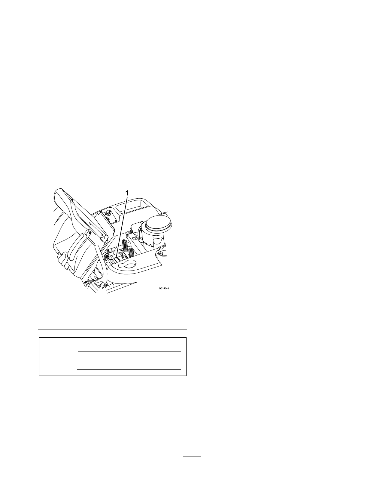
Figure1identiesthelocationofthemodelandserial
numbersontheproduct.Writethenumbersinthe
spaceprovided.
1.Modelandserialnumberlocation
ModelNo.
SerialNo.
Figure1
Undertheseat
3
Page 4

Contents
Introduction...........................................................3
Safety.....................................................................5
SafetyAlertSymbol.........................................5
SafeOperatingPractices..................................5
SafetyandInstructionalDecals.......................9
Specications........................................................14
ModelNumbers.............................................14
Systems..........................................................14
Dimensions....................................................15
TorqueRequirements.....................................16
ProductOverview.................................................16
Operation..............................................................17
Controls.........................................................17
OperatingInstructions...................................18
RecommendedGasoline.................................19
CheckingtheEngineOilLevel........................20
StartingtheEngine.........................................20
OperatingtheBlades......................................21
StoppingtheEngine.......................................21
TheSafetyInterlockSystem............................22
DrivingForwardorBackward.........................22
StoppingtheMachine.....................................24
AdjustingtheHeightofCut............................24
AdjustingtheAnti-ScalpRollers......................24
PositioningtheSeat........................................25
ChangingtheSeatRideSuspension.................26
AdjustingtheMotionControlLevers..............26
PushingtheMachinebyHand.........................26
SideDischarge................................................27
Transporting..................................................27
OperatingTips..............................................28
Maintenance..........................................................30
RecommendedMaintenanceSchedule(s)............30
PremaintenanceProcedures...............................31
RaisingtheSeat..............................................31
PeriodicMaintenance........................................31
Lubrication.....................................................31
EngineMaintenance.......................................32
ServicingtheEngineOil.................................32
ServicingtheSparkPlug.................................34
CleaningtheBlowerHousing..........................35
FuelSystemMaintenance...............................35
ServicingtheEmissionsFilter.........................35
ElectricalSystemMaintenance........................36
ChargingtheBattery.......................................36
DriveSystemMaintenance.............................39
CheckingtheTirePressure.............................39
CheckingtheHydraulicOilLevel....................39
ChangingtheHydraulicSystemFilterand
Oil..............................................................40
MowerMaintenance.......................................42
ServicingtheCuttingBlades...........................42
LevelingtheMowerDeck...............................45
MowerBeltMaintenance................................48
ReplacingtheDischargeDeector..................50
Cleaning............................................................52
WashingtheUndersideoftheMower..............52
CleanEngineandExhaustSystem
Area...........................................................52
Storage..................................................................53
CleaningandStorage......................................53
Troubleshooting....................................................54
Schematics............................................................56
4
Page 5

Safety
Safety
SafetyAlertSymbol
Thismanualidentiespotentialhazardsandhas
safetymessagesidentiedbythesafetyalertsymbol
(Figure2),whichsignalsahazardthatmaycause
seriousinjuryordeathifyoudonotfollowthe
recommendedprecautions.
Figure2
SafetyAlertSymbol
Thismanualusestwootherwordstohighlight
information.Importantcallsattentiontospecial
mechanicalinformationandNoteemphasizes
generalinformationworthyofspecialattention.
Thismachinemeetsorexceedsthesafety
specicationsoftheAmericanNational
StandardsInstituteB71.1-2003ineffectatthe
timeofproduction.However,improperuse
ormaintenancebytheoperatororownercan
resultininjury.Toreducethepotentialfor
injury,complywiththesesafetyinstructions
andalwayspayattentiontothesafetyalert
symbol,whichmeansCAUTION,WARNING,
orDANGER-"personalsafetyinstruction."
Failuretocomplywiththeinstructionmayresult
inpersonalinjuryordeath.
•Allowonlyresponsibleadultswhoarefamiliar
withtheinstructionstooperatethemachine.
•Cleartheareaofobjectssuchasrocks,toys,wire,
etc.,whichcouldbepickedupandthrownbythe
blade.
•Besuretheareaisclearofotherpeoplebefore
mowing.Stopthemachineifanyoneentersthe
area.
•Nevercarrypassengers.
•DoNotmowinreverseunlessabsolutely
necessary.Alwayslookdownandbehindbefore
andwhilebackingup.
•Beawareofthemowerdischargedirectionand
DoNotpointitatanyone.Avoiddischarging
materialagainstawallorobstruction.Material
mayricochetbacktowardtheoperator.Stopthe
bladeswhencrossinggravelsurfaces.
•DoNotoperatethemowerwithouteitherthe
entiregrasscollectionsystemorthedischarge
deectorinplace.
•Bealert,slowdownandusecautionwhen
makingturns.Lookbehindandtothesidebefore
changingdirections.
•Neverleavearunningmachineunattended.
Alwaysturnoffblades,engageparkingbrake,
stopengine,andremovekeybeforedismounting.
•Turnoffbladeswhennotmowing.Stopthe
engine,waitforallpartstocometoacomplete
stop,engageparkingbrake,andremovekey
beforecleaningthemachine,removingthegrass
oruncloggingthedeector.
SafeOperatingPractices
ThefollowinginstructionsarefromANSIstandard
B71.1-2003.
Thisproductiscapableofamputatinghandsand
feetandthrowingobjects.Alwaysfollowallsafety
instructionstoavoidseriousinjuryordeath.
GeneralOperation
•Read,understand,andfollowallinstructionsin
theoperator’smanualandonthemachinebefore
starting.
•DoNotplacehandsorfeetnearrotatingpartsor
underthemachine.Keepclearofthedischarge
openingatalltimes.
•Operatethemachineonlyindaylightorgood
articiallight.
•DoNotoperatethemachinewhileunderthe
inuenceofalcoholordrugs.
•Watchfortrafcwhenoperatingnearorcrossing
roadways.
•Useextracarewhenloadingorunloadingthe
machineintoatrailerortruck
•Alwaysweareyeprotectionwhenoperatingthe
mower.
•Dataindicatesthatoperators,age60yearsand
above,areinvolvedinalargepercentageofriding
mower-relatedinjuries.Theseoperatorsshould
evaluatetheirabilitytooperatetheridingmower
5
Page 6

Safety
safelyenoughtoprotectthemselvesandothers
fromseriousinjury.
•Alwaysfollowtherecommendationsforwheel
weightsorcounterweights.
SlopeOperation
Slopesareamajorfactorrelatedtolossofcontrol
andtip-overaccidents,whichcanresultinsevere
injuryordeath.Operationonallslopesrequiresextra
caution.Ifyoucannotbackuptheslopeorifyoufeel
uneasyonit,DoNotmowit.
•DoNotmowslopesgreaterthan15degrees.
•Watchforditches,holes,rocks,dips,andrisesthat
changetheoperatingangle,asroughterraincould
overturnthemachine.
•Choosealowgroundspeedsoyouwillnothave
tostopwhileoperatingonaslope.
•DoNotmowslopeswhengrassiswet.Slippery
conditionsreducetractionandcouldcausesliding
andlossofcontrol.
•Reducespeedanduseextremecautiononslopes.
•DoNotmakesuddenturnsorrapidspeed
changes.
•Removeormarkobstaclessuchasrocks,tree
limbs,etc.fromthemowingarea.Tallgrasscan
hideobstacles.
•Avoidsuddenstartswhenmowinguphillbecause
themowermaytipbackwards.
•Beawarethatoperatingonwetgrass,acrosssteep
slopesordownhillmaycausethemowertolose
traction.Lossoftractiontothedrivewheelsmay
resultinslidingandalossofbrakingandsteering.
•Alwaysavoidsuddenstartingorstoppingona
slope.Iftireslosetraction,disengagetheblades
andproceedslowlyofftheslope.
•Useextremecarewithgrasscollectionsystemsor
otherattachments.Thesecanchangethestability
ofthemachineandcauselossofcontrol.
•DoNottrytostabilizethemachinebyputting
yourfootontheground.
•DoNotmowneardrop-offs,ditches,steepbanks
orwater.Wheelsdroppingoveredgescancause
rollovers,whichmayresultinseriousinjury,death
ordrowning.
•Useawalkbehindmowerand/orahandtrimmer
onslopesgreaterthan15degrees,neardrop-offs,
ditches,steepbanksorwater.
Children
Tragicaccidentscanoccuriftheoperatorisnot
alerttothepresenceofchildren.Childrenareoften
attractedtothemachineandthemowingactivity.
Neverassumethatchildrenwillremainwhereyou
lastsawthem.
•Keepchildrenoutofthemowingareaandunder
thewatchfulcareofanotherresponsibleadult,
nottheoperator.
•Bealertandturnthemachineoffifchildrenenter
thearea.
•Beforeandwhilebackingorchangingdirection,
lookbehind,down,andside-to-sideforsmall
children.
•Nevercarrychildren,evenwiththebladesoff.
Theymayfalloffandbeseriouslyinjuredor
interferewithsafemachineoperation.
•Childrenwhohavebeengivenridesinthepast
maysuddenlyappearinthemowingareafor
anotherrideandberunoverorbackedoverby
themower.
•Neverallowchildrentooperatethemachine.
•Useextracarewhenapproachingblindcorners,
shrubs,trees,theendofafenceorotherobjects
thatmayobscurevision.
Towing
•UsefortowingonlyifequippedwithanExmark
hitchkit.DoNotattachtowedequipmentexcept
atthehitchpoint.
•FollowExmark’ srecommendationforweight
limitsfortowedequipmentandtowingonslopes.
Thisinformationcanbefoundinthehitchkit
instructionsheetandonthedecal.
•Neverallowchildrenorothersinorontowed
equipment.
•Onslopes,theweightofthetowedequipment
maycauselossoftractionandlossofcontrol.
•Travelslowlyandallowextradistancetostop.
Service
SafeHandlingofGasoline
Toavoidpersonalinjuryorpropertydamage,use
extracarewhenhandlinggasolineandotherfuels.
Theyareammableandthevaporsareexplosive.
6
Page 7

Safety
•Extinguishallcigarettes,cigars,pipesandother
sourcesofignition.
•Useonlyanapprovedcontainer.
•Neverremovethegascaporaddfuelwhenthe
engineisrunning.Allowtheenginetocoolbefore
refueling.
•Neverrefuelthemachineindoors.
•Neverstorethemachineorfuelcontainerinside
wherethereisanopename,suchasnearawater
heaterorfurnace.
•Neverllcontainersinsideavehicleorona
truckortrailerwithaplasticliner.Alwaysplace
containersonthegroundawayfromyourvehicle
beforelling.
•Removegas-poweredequipmentfromthetruck
ortrailerandrefuelitontheground.Ifthisis
notpossible,thenrefuelsuchequipmentwitha
portablecontainer,ratherthanfromagasoline
dispensernozzle.
•Keepthenozzleincontactwiththerimofthe
fueltankorcontaineropeningatalltimesuntil
thefuelingiscomplete.DoNotuseanozzle
lock-opendevice.
•Iffuelisspilledonclothing,changeclothing
immediately.
•Neveroverllthefueltank.Replacegascapand
tightensecurely.
GeneralService:
•Neverrunamachineinsideaclosedarea.
•Keepnutsandboltstight,especiallytheblade
attachmentbolts.Keepequipmentingood
condition.
•Nevertamperwithsafetydevices.Checktheir
properoperationregularly.
•Keepthemachinefreeofgrass,leaves,orother
debrisbuild-up.Cleanupoilorfuelspillageand
fuelsoakeddebris.Allowthemachinetocool
beforestoring.
•Stopandinspecttheequipmentifyoustrikean
object.Repair,ifnecessary,beforerestarting.
•Nevermakeanyadjustmentsorrepairswiththe
enginerunning.
•Grasscollectionsystemcomponentsaresubject
towear,damageanddeterioration,whichcould
exposemovingpartsorallowobjectstobe
thrown.Frequentlycheckcomponentsand
replacewithmanufacturers’recommendedparts,
whennecessary.
•Mowerbladesaresharpandcancut.Wrapthe
bladesorweargloves,anduseextracautionwhen
servicingthem.
•Checkforproperbrakeoperationfrequently.
Adjustandserviceasrequired.
•Maintainorreplacesafetyandinstructiondecals
asnecessary.
•UseonlygenuineExmarkreplacementpartsto
ensurethatoriginalstandardsaremaintained.
ExmarkRidingMowerSafety
Thefollowinglistcontainssafetyinformationspecic
toExmarkproductsorothersafetyinformationthat
youmustknowthatisnotincludedintheANSI
standards.
•Onlyadultsandmatureteenagersshouldoperate
amower,andevenmatureteenagersshouldhave
adultsupervision.Besureateenager:
1.hasreadandunderstandstheOperator's
Manualandrecognizestherisksinvolved;
2.issufcientlymaturetousecaution;and
3.isofsufcientsizeandweighttooperate
thecontrolscomfortablyandtomanagethe
mowerwithouttakingrisks.
•Engineexhaustcontainscarbonmonoxide,which
isanodorless,deadlypoisonthatcankillyou.Do
Notrunengineindoorsorinanenclosedarea.
•Parkmachineonlevelground.Stoptheengine,
waitforallmovingpartstostop,engageparking
brake,disconnectsparkplugwire(s)andremove
keybeforeperforminganyservice,repairs,
maintenanceoradjustments.
•Keephands,feet,hair,andlooseclothingaway
fromattachmentdischargearea,undersideof
mowerandanymovingpartswhileengineis
running.
•DoNottouchequipmentorattachmentparts
whichmaybehotfromoperation.Allowtocool
beforeattemptingtomaintain,adjustorservice.
•Batteryacidispoisonousandcancauseburns.
Avoidcontactwithskin,eyes,andclothing.
Protectyourface,eyes,andclothingwhen
workingwithabattery.
7
Page 8

Safety
•Batterygasescanexplode.Keepcigarettes,sparks
andamesawayfrombattery.
•UseonlyExmarkapprovedattachments.
Warrantymaybevoidedifusedwithunapproved
attachments.
•Ifloadingthemachineontoatrailerortruck,use
asingle,full-widthramponly .Therampangle
shouldnotexceed15degrees.
Note:Theleftandrightsidesofthemachineare
determinedwhilesittingintheseatinthenormal
operatingposition
8
Page 9
SafetyandInstructionalDecals
Safetydecalsandinstructionsareeasilyvisibletotheoperatorandarelocatednearanyareaof
potentialdanger.Replaceanydecalthatisdamagedorlost.
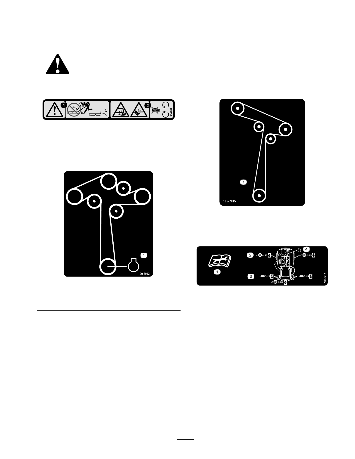
93-7009
1.Warning—don'toperatethemowerwiththedeectorup
orremoved;keepthedeectorinplace.
2.Cutting/dismembermenthazardofhandorfoot,mower
blade—stayawayfrommovingparts.
Safety
105-7015
ForModelswith42InchDecks
1.Beltrouting
99-3943
ForModelswith50InchDecks
1.Engine
1.Readtheinstructionsbeforeservicingorperforming
maintenance.
2.Checktirepressureevery25operatinghours.
3.Greaseevery25operatinghours.
4.Engine
106-8717
9
Page 10
Safety
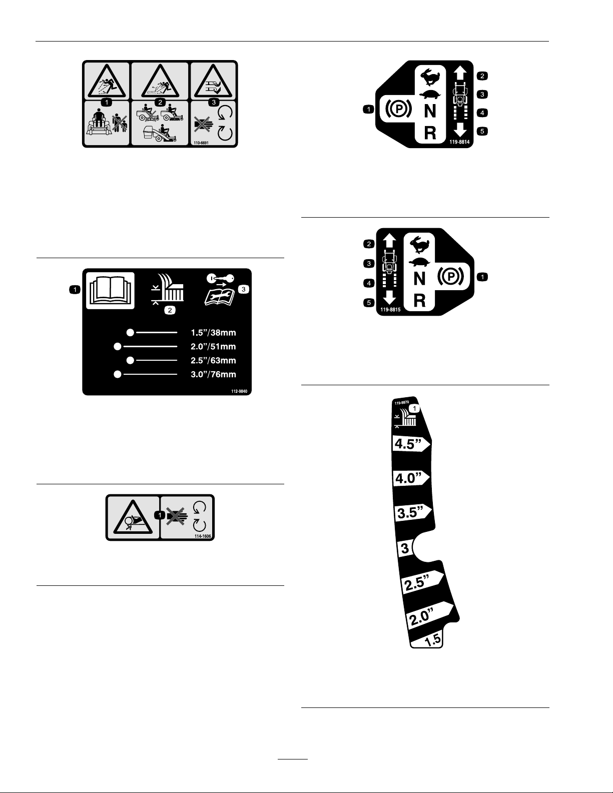
110-6691
1.Thrownobjecthazard—keepbystandersasafedistance
fromthemachine.
2.Thrownobjecthazard,mower—donotoperatewithout
thedeector,dischargecover,orgrasscollection
systeminplace.
3.Cutting/dismembermentofhandorfoot—stayaway
frommovingparts.
112-9840
1.ReadtheOperator's
Manual.
2.Heightofcut
3.Removetheignitionkey
andreadtheinstructions
beforeservicingor
performingmaintenance.
119-8814
1.Parkingposition4.Neutral
2.Fast5.Reverse
3.Slow
119-8815
1.Parkingposition4.Neutral
2.Fast5.Reverse
3.Slow
114-1606
1.Entanglementhazard,belt—keepallguardsinplace.
119-8870
50InchModel
1.Height-of-cut
10
Page 11
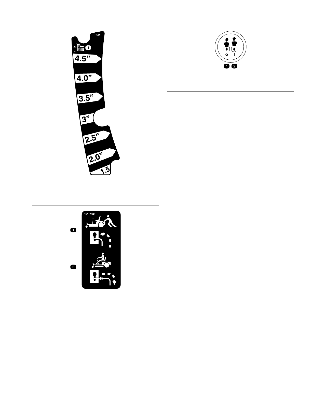
PTOSwitchSymbols
1.PTO–disengage2.PTO–engage
Safety
1.Height-of-cut
1.Bypassleverpositionfor
pushingthemachine
119-8871
42InchModel
121-2989
42InchModel
2.Bypassleverpositionfor
operatingthemachine
11
Page 12

Safety
116-4220
50InchModel
1.Fast
2.Continuousvariablesetting4.Choke
120-5462
42InchModel
1.Fast
2.Continuousvariablesetting4.Choke
3.Slow
3.Slow
12
Page 13
Safety
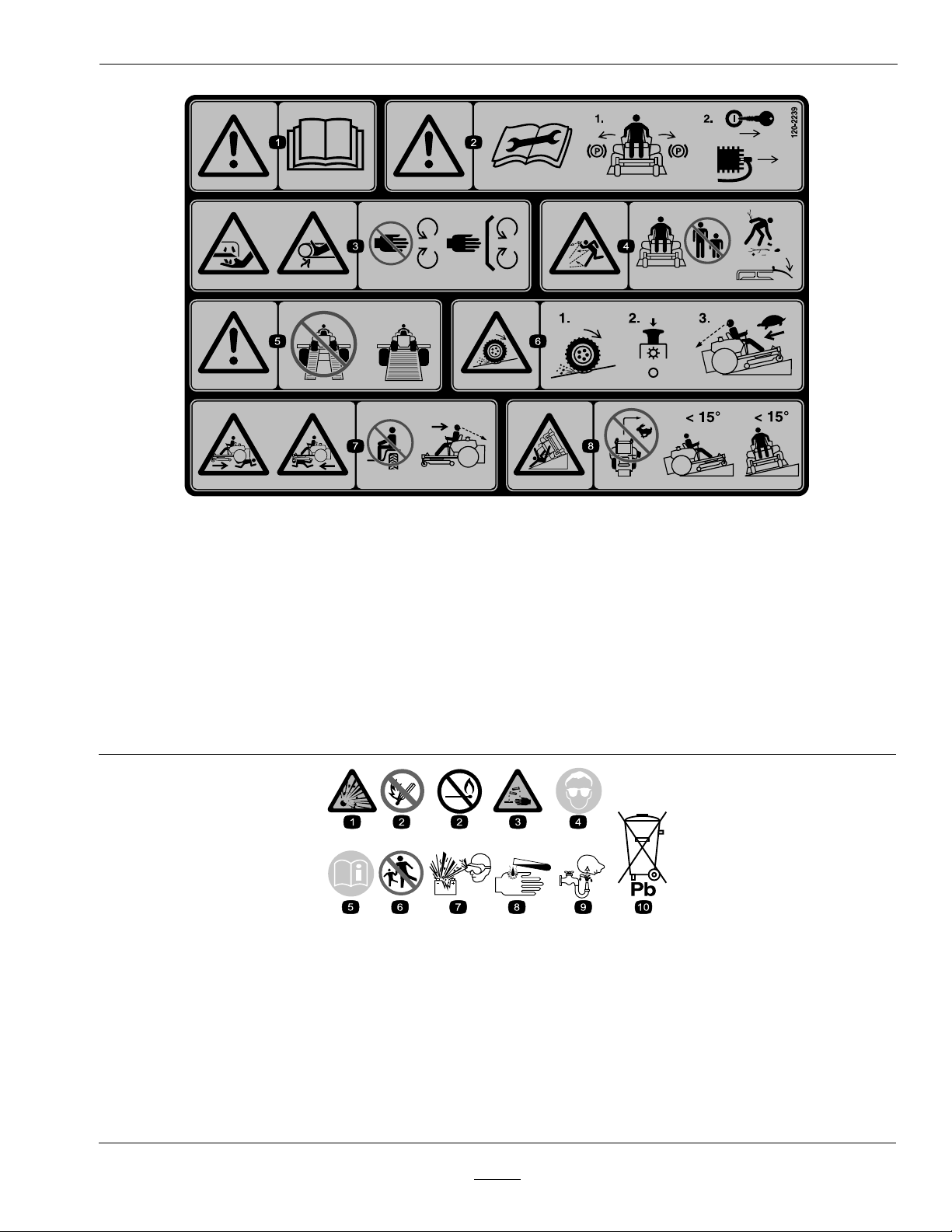
120-2239
1.Warning—readtheOperator'sManual.5.Warning—donotusesplitramps,useafullrampswhen
2.Warning—readtheinstructionsbeforeservicingor
performingmaintenance;movethemotioncontrollevers
tothepark(brake)position,removetheignitionkeyand
disconnectthesparkplugwire.
3.Cutting/dismembermenthazard,mowerblade;
entanglementhazard,belt—stayawayfrommovingparts,
keepallguardsandshieldsinplace.
4.Thrownobjecthazard—keepbystandersasafedistance
fromthemachine,pickupdebrisbeforeoperating,keep
deectorinplace.
transportingmachine.
6.Lossoftraction/controlhazard,slopes—lossof
traction/controlonaslope,disengagethebladecontrol
switch(PTO),proceedofftheslopeslowly.
7.Crushing/dismembermenthazardofbystanders,reversing;
crushing/dismembermenthazardofbystanders—donot
carrypassengers,lookbehindanddownwhenreversing.
8.Tippinghazard—donotmowslopesgreaterthan15
degrees,avoidsuddenandsharpturnswhileonslopes.
BatterySymbols
Someorallofthesesymbolsareonyourbattery .
1.Explosionhazard
2.Nore,openames,orsmoking6.Keepbystandersasafedistance
3.Causticliquid/chemicalburnhazard
4.Weareyeprotection8.Batteryacidcancauseblindnessor
5.ReadtheOperator'sManual.
fromthebattery .
7.Weareyeprotection;explosive
gasescancauseblindnessand
otherinjuries.
severeburns.
13
9.Flusheyesimmediatelywithwater
andgetmedicalhelpfast.
10.Containslead;donotdiscard.
Page 14

Specications
Specications
ModelNumbers
SerialNos:312,000,000andHigher
QTE651KA421;QTE691KA501;QTS691KA502
Systems
Engine
•EngineSpecications:SeeyourEngineOwner’ s
Manual
•EngineOilT ype:Exmark4-CyclePremium
EngineOil
•RPM:
FullSpeed:3300±100(max)RPM(NoLoad)
Idle:1650(min)RPM
FuelSystem
•Capacity:3.0gal.(11.4L)
•FuelRecommendations:
–Forbestresults,useonlyclean,fresh,unleaded
gasolinewithanoctaneratingof87orhigher
((R+M)/2ratingmethod).
–Oxygenatedfuelwithupto10%ethanolor
15%MTBEbyvolumeisacceptable.
–DoNotuseethanolblendsofgasoline(such
asE15orE85)withmorethan10%ethanol
byvolume.Performanceproblemsand/or
enginedamagemayresultwhichmaynotbe
coveredunderwarranty.
–DoNotusegasolinecontainingmethanol.
–DoNotstorefueleitherinthefueltankor
fuelcontainersoverthewinterunlessafuel
stabilizerisused.
–DoNotaddoiltogasoline.
•FuelFilter:
•Polarity:NegativeGround
•Fuses:One30amp,one25amp;bladetype
SafetyInterlockSystem
•PTOmustbedisengaged,motioncontrollevers
out(brakeengaged)tostartengine.(Itisnot
necessaryfortheoperatortobeintheseatto
starttheengine.)
•OperatormustbeinseatwhenPTOisengaged
ormotioncontrolleversaremovedinorengine
willstop.
OperatorControls
•SteeringandMotionControl:
Note:Motioncontrolleversareadjustableto
twoheights.
–Separatelevers,oneachsideoftheconsole,
controlspeedanddirectionoftravelofthe
respectivedrivewheels.
–Steeringiscontrolledbyvaryingtheposition
oftheleversrelativetoeachother.
–Movingmotioncontrolleversoutward(in
slots)locksthedrivesysteminneutraland
appliestheparkingbrake.
•PTOEngagementSwitch:Engageselectricclutch
(todrivebelt)whichengagesmowerblades.
•DeckHeightAdjustmentLever:Setscutting
heighttodesiredposition.
•DeckLiftAssistLever:Footpedalthatassistsin
raisingthedeck.
KawasakiP/N49019-7005
ElectricalSystem
•ChargingSystem:FlywheelAlternator
•ChargingCapacity:15amps
•BatteryType:195CCA
•BatteryVoltage:12Volt
Seat
•Type:
–42inchunit:Standardseatwithhighback,
foampaddedwithspringsuspensionand
armrests.
–50inchunit:Twotoneupholsteredseatwith
springsuspensionandarmrests.
14
Page 15

Specications
•Mounting:Hingedtotiltupforaccesstobattery
andothercomponents.Adjustableforeandaft.
•Armrests:Standard–paddedip-uparmrests.
•SeatSafetySwitch:IncorporatedintotheSafety
InterlockSystem.
HydrostaticGroundDriveSystem
•HydrostaticPumps:
–42inchunit:TwoHydroGearZT2100
Integrateddrivesystems.
–50inchE-Seriesunit:TwoHydroGear
ZT2200Integrateddrivesystems.
–50inchS-Seriesunit:TwoHydroGear
ZT2800Integrateddrivesystems.
•HydraulicOilType:ExmarkPremiumHydroOil.
•Speeds:
–0-7.0mph(11.3km/hr)forward.
–0-5.0mph(8.0km/hr)reverse.
•Drivewheelreleases,locatedonleftandright
sidesofenginedeck,allowmachinetobemoved
whentheengineisnotrunningandbrakeisoff.
CuttingDeck
•CuttingWidth:
–42inchDeck:42inches(107cm)
–50inchDeck:50inches(127cm)
•Discharge:Side
•BladeSize:
–42inchDeck:21.60inches(54.9cm)–Qty:2
–50inchDeck:17.50inches(44.5cm)–Qty:3
•BladeSpindles:Solidsteelspindleswithno
maintenancebearings.
•DeckDrive:Electricclutchmountedonvertical
engineshaft.Bladesaredrivenbyonebelt
(w/self-tensioningidler)directfromtheengine.
•Deck:Fulloatingdeckisattachedtoout-front
supportframe.Maximumturfprotectionis
providedwithanti-scalprollers.
Deckdesignallowsforbagging,mulchingorside
discharge.
•DeckDepth:
–42inchDeck:4.0inches(10.2cm)
TiresandWheels
Drive
Pneumatic(Air-Filled)
DeckSize
Quantity
Tread
Size18x7.50-818x9.50-820x8-10
PlyRating
Pressure
DeckSize
Quantity
Tread
Size
PlyRating
Pressure
4250E-Series50S-Series
222
Hoosier
Premium
2
13psi
(90kPa)
4250
22
Smooth
410/350x4
22
20psi
(138kPa)
Hoosier
Premium
44
13psi
(90kPa)
FrontCaster
Pneumatic(Air-Filled)
Ribbed
13x5-6
13psi
(90kPa)
CarlisleTurf
Master
13psi
(90kPa)
–50inchDeck:4.0inches(10.2cm)
•CuttingHeightAdjustment:Ahanddeckliftlever
withfootassistisusedtoadjustthecuttingheight
from11/2inch(3.8cm)to41/2inches(11.4
cm)in1/2inch(1.3cm)increments.
•MulchingKit:Optional.
Dimensions
OverallWidth:
42inchDeck50inchDeck
WithoutDeck39.0inches
(99cm)
DeectorUp45.3inches
(115cm)
DeectorDown53.8inches
(137cm)
OverallLength:
42inchDeck50inchDeck
71.8inches(182cm)72.9inches(185cm)
46.3inches
(118cm)
54.6inches
(139cm)
63.0inches
(160cm)
15
Page 16
ProductOverview
OverallHeight:
AllUnits
41.5inches(105cm)
TreadWidth:(CentertoCenterof
Tires,Widthwise)
42inchDeck50inchDeck
DriveWheels31.5inches
(80cm)
CasterWheels29.5inches
(75cm)
37.4inches
(95cm)
36.9inches
(94cm)
WheelBase:(CenterofCasterTireto
CenterofDriveTire)
AllUnits
45.6inches(116cm)
CurbWeight:
42inchDeck50inchE-Series
Deck
531lb(241kg)614lb(279kg)672lb(305kg)
50inchS-Series
Deck
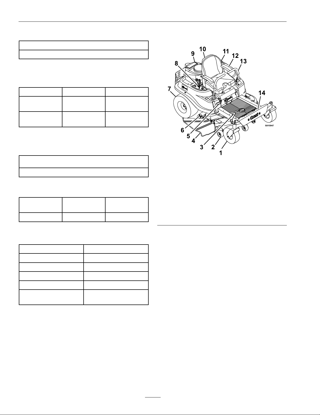
ProductOverview
Figure3
1.Frontcasterwheel
2.Anti-scalproller9.Engine
3.Height-of-cutfootlever10.Seat
4.Dischargedeector
5.Deckheightadjustment
lever
6.Washouttting
7.Reardrivewheel14.Footrest
8.Controlpanel
11.Fueltank
12.Armrest
13.Motioncontrollevers
TorqueRequirements
BoltLocation
SpindlePulleyNut35-65ft-lb(47-88N-m)
BladeMountingBolt35-65ft-lb(47-88N-m)
EngineMountingBolts
WheelLugNuts
ClutchMountingBolt
(securedwiththreadlocker)
Torque
330-400in-lb(37-45N-m)
70-90ft-lb(95-122N-m)
50-60ft-lb(68-81N-m)
16
Page 17
Operation
Operation
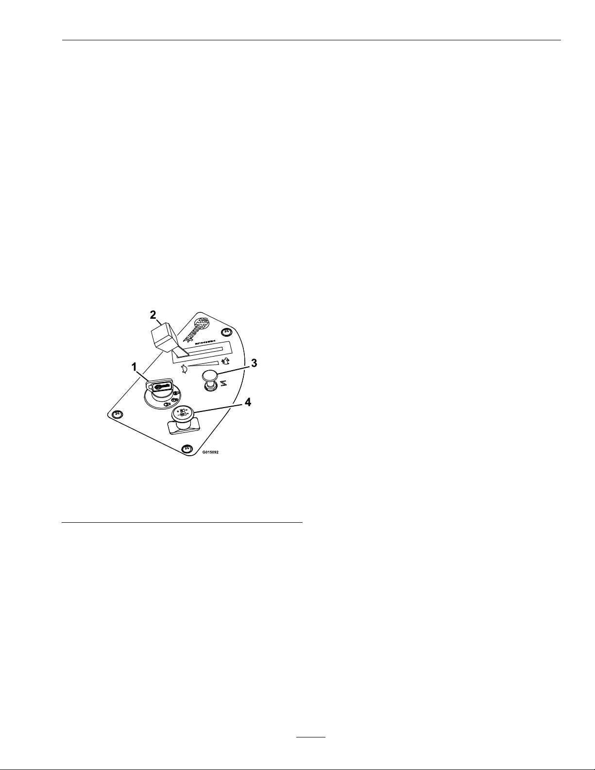
Controls
Note:Becomefamiliarwithallofthecontrolsin
Figure3andFigure4beforeyoustarttheengineand
operatethemachine.
IgnitionSwitch
Locatedoncontrolpanel.
Theignitionswitchisusedtostartandstopthe
engine.Theswitchhasthreepositions“OFF”,
“RUN”and“START”(
switchandrotateclockwisetothe“ON”position.
Rotateclockwisetothenextpositiontoengagethe
starter(keymustbeheldagainstspringpressurein
thisposition).
Figure4).Insertkeyinto
BladeControlSwitch(Power
Take-Off)
Locatedonthecontrolpanel.
Thebladecontrolswitch,representedbyapower
take-off(PTO)symbol,engagesanddisengages
powertothemowerblades(see
Pulloutonthebladecontrolswitchto“On”to
engagetheblades.
Pushthebladecontrolswitchto“Off”todisengage
theblades.
Figure4).
ThrottleLever
Locatedoncontrolpanel.
Thethrottleisusedtocontrolenginespeed.Moving
throttleleverforwardwillincreaseenginespeedand
movingthrottlelevertotherearwilldecreaseengine
speed.Movingthethrottleforwarduntilitstopsis
fullthrottle(see
Figure4).
Figure4
1.Ignitionswitch
2.Throttlelever4.Bladecontrolswitch
Note:Brakemustbeengaged(motioncontrollevers
out)andPTOswitch“OFF”tostartengine.(Itis
notnecessaryfortheoperatortobeintheseatto
starttheengine.)
TurningthekeytotheOffpositionwillstopthe
engine;however,alwaysremovethekeywhenleaving
themachinetopreventsomeonefromaccidentally
startingtheengine.
3.Chokecontrol
(powertake-off)
ChokeControl
Thechokeisusedtoaidinstartingacoldengine.
Pullinguponthechokecontrolwillputthechokein
the“ON”positionandpushingdownthecontrolwill
putthechokeinthe“OFF”position.DoNotruna
warmenginewiththechokeinthe“ON”position.
MotionControlLeversandParking
BrakePosition
Themotioncontrolleverslocatedoneachsideof
theseat(Figure3).
Themotioncontrolleversarespeedsensitivecontrols
ofindependentwheelmotors.Movingalever
forwardorbackwardturnsthewheelonthesameside
forwardorinreverse;wheelspeedisproportionalto
theamounttheleverismoved.Movingthecontrol
leversoutwardfromthecenterpositionengagesthe
parkingbrakeonthedrivewheels.Alwaysposition
themotioncontrolleversintotheparkingbrake
positionwhenyoustopthemachineorleaveit
unattended.Theunitmustbetieddownandbrake
engagedwhentransporting.
DeckHeightAdjustmentLever
LocatedbelowtheRHmotioncontrollever
(Figure3).
17
Page 18
Operation
Pulltheleverinwardandrearwardtoraisethecutting
deck.Allowthehandletomoveforwardtolowerthe
cuttingdeck.Movethedeckheightadjustmentlever
outwardatthedesiredheight-of-cut.Onlyadjustthe
heightofcutwhilethemachineisnotmoving.
Height-of-CutFootLever
Theheight-of-cutfootleverallowstheoperatorto
usetheirlegtoassistinloweringandraisingthedeck
fromtheseatedposition(Figure3).Whenthelever
ismovedforward,awayfromtheoperatorthedeck
israisedfromthegroundandwhenmovedback,
towardstheoperatoritisloweredtowardtheground.
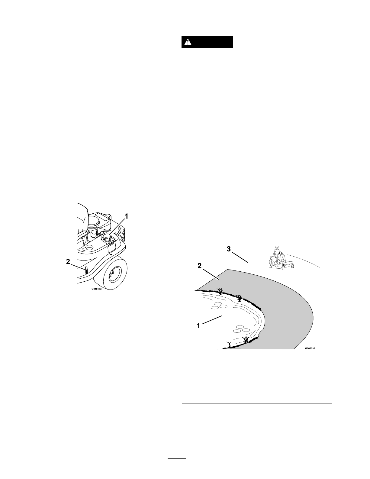
FuelWindow
Locatedontheleftsideofthemachine(seeFigure5).
Thefuelwindowcanbeusedtoverifythepresence
offuelinthetank.
DANGER
Mowingonwetgrassorsteepslopescancause
slidingandlossofcontrol.Wheelsdropping
overedgescancauserollovers,whichmayresult
inseriousinjury,deathordrowning.Alossof
tractionisalossofsteeringcontrol.
Toavoidlossofcontrolandpossibilityofrollover:
•DoNotmowneardrop-offsornearwater.
•DoNotmowslopesgreaterthan15degrees.
•Reducespeedanduseextremecautionon
slopes.
•Whenmowingslopes,graduallyworkfrom
lowertohigherareasontheincline.
•Avoidsuddenturnsorrapidspeedchanges.
•Turnup,intoaninclinewhenchanging
directionsonslopes.Turningdowntheslope
reducestraction.
•Attachmentschangethehandling
characteristicsofthemachine.Useextra
cautionwhenusingattachmentswiththe
machine.
Figure5
1.Fuelcap2.Fuelwindow
OperatingInstructions
ThinkSafetyFirst
Note:Determinetheleftandrightsidesofthe
machinefromthenormaloperatingposition.
Pleasecarefullyreadallofthesafetyinstructionsand
decalsinthesafetysection.Knowingthisinformation
couldhelpyou,yourfamily,petsorbystandersavoid
injury.
Figure6
1.Water
2.DangerZone–Usewalkbehindmowerand/orhand
trimmeronslopesgreaterthan15degrees,near
drop-offsandwater.
3.SafeZone–usetheQuesthere.
Seeinsidebackcovertodeterminetheapproximate
slopeangletobemowed.
18
Page 19

Operation
RecommendedGasoline
Fillfueltankonlevelground.SeeFuel
RecommendationsintheSpecicationssectionfor
additionalgasolineinformation.
DoNotaddoiltogasoline.
DoNotoverllfueltank.Fillthefueltanktothe
bottomofthellerneck.Theemptyspaceinthe
tankallowsgasolinetoexpand.Overllingmayresult
infuelleakageordamagetotheengineoremission
system.
DANGER
Incertainconditionsgasolineisextremely
ammableandvaporsareexplosive.
Areorexplosionfromgasolinecanburnyou,
others,andcausepropertydamage.
•Fillthefueltankoutdoorsonlevelground,in
anopenarea,whentheengineiscold.Wipe
upanygasolinethatspills.
•Neverrellthefueltankordrainthemachine
indoorsorinsideanenclosedtrailer.
•DoNotllthefueltankcompletelyfull.Add
gasolinetothefueltankuntilthebodyofthe
tankisfullbutfueldoesnotlltheneckof
thetank.Thisemptyspaceinthetankallows
gasolinetoexpand.
•Neversmokewhenhandlinggasoline,and
stayawayfromanopenameorwhere
gasolinefumesmaybeignitedbyspark.
•Storegasolineinanapprovedcontainerand
keepitoutofthereachofchildren.Never
buymorethana30-daysupplyofgasoline.
•DoNotoperatewithoutentireexhaustsystem
inplaceandinproperworkingcondition.
DANGER
Incertainconditionsduringfueling,static
electricitycanbereleasedcausingasparkwhich
canignitegasolinevapors.Areorexplosion
fromgasolinecanburnyouandothersandcause
propertydamage.
•Alwaysplacegasolinecontainersonthe
groundawayfromyourvehiclebeforelling.
•DoNotllgasolinecontainersinsidea
vehicleoronatruckortrailerbedbecause
interiorcarpetsorplastictruckbedliners
mayinsulatethecontainerandslowtheloss
ofanystaticcharge.
•Whenpractical,removegas-powered
equipmentfromthetruckortrailerandrefuel
theequipmentwithitswheelsontheground.
•Ifthisisnotpossible,thenrefuelsuch
equipmentonatruckortrailerfroma
portablecontainer,ratherthanfroma
gasolinedispensernozzle.
•Ifagasolinedispensernozzlemustbeused,
keepthenozzleincontactwiththerimofthe
fueltankorcontaineropeningatalltimes
untilfuelingiscomplete.
WARNING
Gasolineisharmfulorfatalifswallowed.
Long-termexposuretovaporshascausedcancer
inlaboratoryanimals.Failuretousecautionmay
causeseriousinjuryorillness.
•Avoidprolongedbreathingofvapors.
•Keepfaceawayfromnozzleandgas
tank/containeropening.
•Keepawayfromeyesandskin.
•Neversiphonbymouth.
UsingStabilizer/Conditioner
Useafuelstabilizer/conditionerinthemachineto
providethefollowingbenets:
•Keepsgasolinefreshduringstorageof30daysor
less.Forlongerstorageitisrecommendedthat
thefueltankbedrained.
•Cleanstheenginewhileitruns.
•Eliminatesgum-likevarnishbuildupinthefuel
system,whichcauseshardstartingAddthe
19
Page 20
Operation
correctamountofgasstabilizer/conditionerto
thegas.
Note:Afuelstabilizer/conditionerismosteffective
whenmixedwithfreshgasoline.Tominimizethe
chanceofvarnishdepositsinthefuelsystem,usefuel
stabilizeratalltimes.
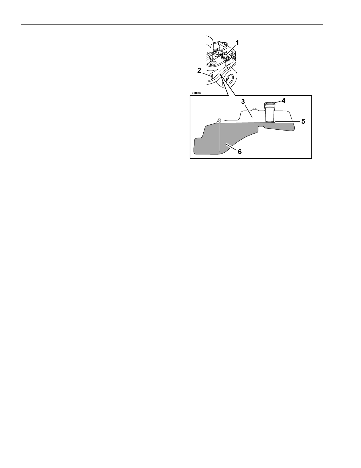
FillingtheFuelTank
Makesuretheengineisshutoffandthemotion
controlsareintheparkposition.Tankmaximum
capacityis2.9gallons.
Important:DoNotoverllfueltank.Fillthe
fueltanktothebottomofthellerneck.The
emptyspaceinthetankallowsthefueltoexpand.
Overllingmayresultinfuelleakageordamage
totheengineoremissionsystem.
1.Shuttheengineoffandmovethemotioncontrols
outwardtoengageparkingbrake.
2.Cleanaroundthefueltankcapandremovethe
cap.
Figure7
1.Fuelcap4.Fillopening
2.Fuelwindow
3.Emptyspaceforfuel
expansion
5.Baseofllerneck,DO
NOTFILLPASTHERE
6.Fuel
3.Addunleadedregulargasolineuntilthefuel
reachesthebaseofthellerneckanddoesnot
lltheneckofthetank(
Figure7).Thisspace
atthebaseofthellerneckallowsgasolineto
expand.DoNotllthefueltankcompletelyfull.
Overllingmayresultinfuelleakageordamage
totheengineoremissionssystem.
4.Installthefueltankcapsecurelyandtightenuntil
it“clicks”.Wipeupanygasolinethatmayhave
spilled.
CheckingtheEngineOil
Level
Beforeyoustarttheengineandusethemachine,
checktheoillevelintheenginecrankcase;referto
CheckingtheOilLevelinEngineMaintenance
section.
StartingtheEngine
1.Sitdownontheseatandmovethemotion
controlsoutwardtoengagetheparkingbrake.
2.Disengagethebladesbymovingthebladecontrol
switchtoOff(Figure8).
20
Page 21

Figure8
1.Ignitionkey5.Throttlelever
2.Off6.Chokecontrol
3.Run7.Bladecontrol
switch—Offposition
4.Start
Operation
2.MovethethrottlemidwaytotheFastposition.
Note:Alwaysengagethebladeswiththethrottle
inthemidwayposition.
3.Pulloutonthebladecontrolswitch,totheOn
position,toengagetheblades(
Figure9).
3.Pulluponthechokecontroltoengagethechoke
beforestartingacoldengine(Figure8).
Note:Awarmorhotenginemaynotrequire
choking.
4.TurntheignitionkeytoStarttoenergizethe
starter.Whentheenginestarts,releasethekey
Figure8).
(
Important:DoNotengagethestarterfor
morethan5secondsatatime.Iftheengine
failstostart,allowa60secondcool-down
periodbetweenattempts.Failuretofollow
theseinstructionscanburnoutthestarter
motor.
5.Oncetheenginestarts,graduallypushdownthe
chokecontrolastheenginewarms.Iftheengine
stallsorhesitates,slightlypullthecontrolupfor
afewseconds.
OperatingtheBlades
Thebladecontrolswitch,representedbyapower
take-off(PTO)symbol,engagesanddisengages
powertothemowerblades.Thisswitchcontrols
powertoanyattachmentsthatdrawpowerfromthe
engine,includingthemowerdeckandcuttingblades.
EngagingtheBlades
Figure9
1.Throttle–Midwayposition2.Bladecontrol
switch—Onposition
4.Movethrottletofullforwardpositionbefore
mowing.
DisengagingtheBlades
Setthrottletomidwayposition.Pushtheblade
controlswitchtoOfftodisengagetheblades
(Figure8).
StoppingtheEngine
1.Bringtheunittoafullstop.
2.Disengagetheblades.
3.Movethemotioncontrolleversouttoengagethe
parkingbrake.
4.Placethethrottlemidwaybetweenthe“SLOW”
and“FAST”positions.
5.Allowtheenginetorunforaminimumof15
seconds,thenturntheignitionswitchtothe
“OFF”positiontostoptheengine.
6.Removethekeytopreventchildrenorother
unauthorizedpersonsfromstartingengine.
1.Releasepressureonthemotioncontrolleversand
placethemachineinneutral.
21
Page 22

Operation
TheSafetyInterlockSystem
CAUTION
Ifthesafetyinterlockswitchesaredisconnected
ordamagedthemachinecouldoperate
unexpectedlycausingpersonalinjury.
•Donottamperwiththeinterlockswitches.
•Checktheoperationoftheinterlockswitches
dailyandreplaceanydamagedswitches
beforeoperatingthemachine.
UnderstandingtheSafetyInterlock
System
Thesafetyinterlocksystemisdesignedtopreventthe
enginefromstartingunless:
•Thebladesaredisengaged.
•Themotioncontrolleversareintheneutral
position.
•Theparkingbrakeisengaged.
Thesafetyinterlocksystemisdesignedtoinitiate
engineshutdownwhen:
•Theparkingbrakeisdisengagedandtheoperator
getsoffmachine.
•ThePTOisengagedandtheoperatorgetsoff
machine.
•Theparkingbrakeisdisengagedandleversarein
andtheoperatorgetsoffmachine.
TestingtheSafetyInterlockSystem
donotgetoffofmachine)enginemustinitiate
shutdown.
Runengineatone-thirdthrottle,withbrake
disengaged,moveleversinandraiseoffseat(but
donotgetoffofmachine)enginemustinitiate
shutdown.
Note:Ifmachinedoesnotpassanyofthesetests,
DoNotoperate.ContactyourauthorizedEXMARK
SERVICEDEALER.
Important:Itisessentialthatoperatorsafety
mechanismsbeconnectedandinproper
operatingconditionpriortouseformowing.
DrivingForwardorBackward
Thethrottlecontrolregulatestheenginespeedas
measuredinrpm(revolutionsperminute).Place
thethrottlecontrolintheFastpositionforbest
performance.AlwaysoperateintheFast(fullthrottle)
position.
CAUTION
Machinecanspinveryrapidlybypositioningone
levertoomuchaheadoftheother.Operatormay
losecontrolofthemachine,whichmaycause
damagetothemachineorinjury.
•Usecautionwhenmakingturns.
•Slowthemachinedownbeforemakingsharp
turns.
Testthesafetyinterlocksystembeforeyouusethe
machineeachtime
1.Checkstartingcircuit.Startershouldcrankwith
thePTOdisengagedandmotioncontrollevers
movedoutintheparkingbrakeposition.The
operatordoesnotneedtobeintheseattostart
theengine.
Trytostartwithoperatorinseat,PTO
disengagedandmotioncontrolleversinthe
parkingbrakeposition-startermustnotcrank.
Trytostartwithoperatorinseat,PTO
disengaged,andtheleftmotioncontrollever
in,startermustnotcrank,repeatagainwiththe
rightleverin,thenwithbothleversin-starter
mustnotcrank.
2.Checkkillcircuits.Runengineatone-third
throttle,engagePTOandraiseoffofseat(but
Forward
1.Movetheleverstothecenter,unlockedposition.
2.Togoforward,slowlypushthemotioncontrol
leversforward(
22
Figure10).
Page 23

Operation
G008952
Figure10
1.Parkingbrakeposition
(engaged)
2.Centerunlockposition
(neutral)
3.Frontofunit
4.Forward
5.Backward
Togostraight,applyequalpressuretoboth
motioncontrollevers(
Figure10andFigure11).
Figure11
Toturn,pullbackonthemotioncontrol
levertowardthedirectionyouwanttoturn
(Figure10andFigure11).
Thefartheryoumovethemotioncontrollevers
ineitherdirection,thefasterthemachinewill
moveinthatdirection.
Tostop,pullthemotioncontrolleverstoneutral.
Backward
1.Movetheleverstothecenter,unlockedposition.
2.Togobackward,slowlypullthemotioncontrol
leversrearward(Figure10andFigure12).
23
Page 24

Operation
G008953
adjustmentleverinwardandpullingup.The
heightcanalsobeadjustedbymovingthedeck
heightadjustmentleverinwardandpushingthe
height-of-cutfootleverforward(
transportleverwillautomaticallyengageandwill
dropintoplace.
Figure12
Figure13).The
Togostraight,applyequalpressuretoboth
motioncontrollevers(Figure10andFigure12).
Toturn,releasethepressureonthemotion
controllevertowardthedirectionyouwantto
turn(Figure10andFigure12).
Tostop,pushthemotioncontrolleverstoneutral.
StoppingtheMachine
Tostopthemachine,movethemotioncontrollevers
toneutral,disengagethebladecontrolswitch,move
themotioncontrolleversoutwardtoengagethe
parkingbrake,movethethrottlelevertobetween
Fastandhalfthrottle,andturntheignitionkeyto
off.Remembertoremovethekeyfromtheignition
switch.
CAUTION
Childrenorbystandersmaybeinjuredifthey
moveorattempttooperatethemowerwhileit
isunattended.
Alwaysremovetheignitionkeyandmove
themotioncontrolleversoutwardtoapply
theparkingbrakewhenleavingthemachine
unattended,evenifjustforafewminutes.
AdjustingtheHeightofCut
1.Raisethedecktothetransportposition(4.5inch
(114mm)cutheight)bymovingthedeckheight
Figure13
1.Height-of-cutfootlever3.Height-of-cutpositions
2.Deckheightadjustment
lever
2.Pushthefootleverforward,pullthedeckheight
adjustmentleverhandleinwardandletthedeck
lowerdowntothedesiredcutheightbyslowly
decreasingfootpressureallowingthefootleverto
travelrearward.Movethedeckheightadjustment
leveroutwardatthedesiredheight-of-cut.
4.Transportposition–4.5
inch(115mm)
AdjustingtheAnti-Scalp
Rollers
Itisrecommendedtochangetheanti-scalproller
positionwhentheheightofcuthaschanged.
1.Stopthemachineandmovethedriveleversto
theneutralposition.
2.DisengagethePTO.
3.Movethemotioncontrolleversoutwardto
engagetheparkbrake.
4.Stoptheengine,removethekeyandwaitforall
movingpartstostop.
5.Afteradjustingtheheightofcut,adjustthe
anti-scalprollersbyremovingthenylocnut.
6.Adjusttheanti-scalprollersforthenormal
operatingconditions.Placerollersinoneof
24
Page 25

Operation
G014477
1
thepositionsshowninFigure15.Rollerswill
maintain3/4inches(19mm)clearancetothe
groundtominimizegougingandrollerwearor
damage.
Note:ForMaximumDeckFlotation,place
therollersoneholepositionlower.Rollersshould
maintain1/4inch(6.35mm)clearancetothe
ground.DoNotadjustrollerstosupportthe
deck.
Figure14
42InchDeck
1.Anti-scalprollermountingbracket
2.Below21/2inches(64mm)cuttingheight
3.21/2inches(64mm)andabovecuttingheight
1.Tiptheseatforward.
2.Loosentheadjustmentbolts.
Figure16
1.Adjustmentbolt
3.Movetheseattothedesiredpositionand
tightenbolts.
4.Tiptheseatbacktotheclosedposition.
•50InchUnits:
1.Pushtheadjustmentlevertowardsthecenter
ofthemachinetoreleasetheseatadjuster
Figure17).
track(
Figure15
50InchDeck
Forcuttingheightsabove31/2inches(90mm)
usethebottomhole.Therollerswillstillbeeffective
againstscalping.
1.Anti-scalproller
mountingbracket
7.Torquehardwareto27-33ft-lb(37-45N-m)or
2.Cuttingheight
Figure17
lossofrollermayresult.
1.Adjustmentlever
PositioningtheSeat
2.Movetheseattothedesiredpositionand
Theseatcanmoveforwardandbackward.Position
releasethelevertolockinthatposition.
theseatwhereyouhavethebestcontrolofthe
machineandaremostcomfortable.
•42InchUnit:
25
Page 26

Operation
ChangingtheSeatRide
Suspension
Thenumberofseatspringscanbechangedto
maximizeridercomfort.Morespringsshouldbeused
withheavieroperatorsandonroughterrain.Fewer
springsshouldbeusedwithlighteroperatorsand
whenmowingsmooth,wellestablishedlawns.Always
keepthenumberofspringsontheleftandrightside
thesamewhenaddingandremovingsprings.
Figure19
Figure18
1.Bolt3.Nut
2.Spring
Uptovespringscanbesecuredtotheseatboxwith
anutandbolt,seeFigure18.
RefertoyourPartsManualforspringandhardware
partnumbers.
4.Additionalmounting
holes
1.Controlarmshaft
2.Controllever
2.Movethecontrollevertothenextsetofholes.
Securetheleverwiththehardware.
3.Repeattheadjustmentfortheoppositecontrol
lever.
3.Washer
4.Bolt
AdjustingtheTilt
Themotioncontrolleverscanbetiltedforeoraftfor
maximumoperatorcomfort.
1.Loosentheupperboltholdingthecontrollever
tothecontrolarmshaft.
2.Loosenthelowerboltjustenoughtopivotthe
controlleverforeoraft(
boltstosecurethecontrolinthenewposition.
3.Repeattheadjustmentfortheoppositecontrol
lever.
Figure19).Tightenboth
AdjustingtheMotionControl
Levers
AdjustingtheHeight
Themotioncontrolleverscanbeadjustedhigheror
lowerformaximumoperatorcomfort.
1.Removethehardwareholdingthecontrolleverto
thecontrolarmshaft(Figure19).
PushingtheMachineby
Hand
Important:Alwayspushthemachinebyhand.
Nevertowthemachinebecausedamagemay
occur.
Thismachinehasanelectricbrakemechanismandto
pushthemachinetheignitionkeyneedstobeinthe
Runposition.Thebatteryneedstobechargedand
functioningfortheelectricbraketobedisengage.
ToPushtheMachine
1.Parkthemachineonalevelsurfaceanddisengage
thebladecontrolswitch.
26
Page 27

Operation
g017303
1 2
3
2.Movethemotioncontrolleversoutwardtopark
position,stoptheengine,andwaitforallmoving
partstostopbeforeleavingtheoperatingposition.
3.Locatethebypassleversontheframeonboth
sidesoftheengine.
4.Movethebypassleversforwardthroughthekey
holeanddowntolocktheminplaceasshownin
Figure20.Ensurethisisdoneforeachlever.
5.Movethemotioncontrolleversinwardtothe
neutralpositionandturntheignitionkeytothe
runposition.DoNotstartthemachine.
Themachineisnowabletobepushedbyhand.
SideDischarge
Themowerhasahingeddischargedeectorthat
dispersesclippingstothesideanddowntowardthe
turf.
DANGER
Withoutthedischargedeector,mulchkit,or
entiregrasscollectionsystemmountedinplace,
youandothersareexposedtobladecontactand
throwndebris.Contactwithrotatingmower
blade(s)andthrowndebriswillcauseinjuryor
death.
•Neverremovethedischargedeectorfrom
themowerbecausethedischargedeector
routesmaterialdowntowardtheturf.Ifthe
dischargedeectoriseverdamaged,replace
itimmediately.
•Neverputyourhandsorfeetunderthe
mower.
•Nevertrytocleardischargeareaormower
bladesunlessyoumovethemovetheblade
controlswitchtoOffandrotatetheignition
keytoOff.Alsoremovethekeyandpullthe
wireoffthesparkplug(s).
Figure20
1.Bypassleverlocation
2.Leverpositionfor
operatingthemachine
3.Leverpositionfor
pushingthemachine
6.Whennished,ensurethekeyhasbeenreturned
totheStoppositiontoavoiddrainingthebattery
charge.
Ifthemachinefailstomovetheelectricbrakemay
stillbeengaged.Ifnecessarytheelectricbrakecan
bereleasedmanually.RefertotheReleasingthe
ElectricBrakeprocedureinDriveMaintenance.
ToOperatetheMachine
Movethebypassleversrearwardthroughthekey
holeanddowntolocktheminplaceasshownin
Figure20.Ensurethisisdoneforeachlever.
Transporting
TransportingaUnit
Useaheavy-dutytrailerortrucktotransportthe
machine.Lockbrakeandblockwheels.Securely
fastenthemachinetothetrailerortruckwithstraps,
chains,cable,orropes.Besurethatthetrailerortruck
hasallnecessarylightingandmarkingasrequiredby
law .Secureatrailerwithasafetychain.
CAUTION
Thisunitdoesnothaveproperturnsignals,
lights,reectivemarkings,oraslowmoving
vehicleemblem.Drivingonastreetorroadway
withoutsuchequipmentisdangerousand
canleadtoaccidentscausingpersonalinjury.
Drivingonastreetorroadwaywithoutsuch
equipmentmayalsobeaviolationofStatelaws
andtheoperatormaybesubjecttotrafctickets
and/ornes.
DoNotdriveaunitonapublicstreetorroadway.
27
Page 28

Operation
WARNING
Loadingaunitonatrailerortruckincreases
thepossibilityofbackwardtip-over.Backward
tip-overcouldcauseseriousinjuryordeath.
•Useextremecautionwhenoperatingaunit
onaramp.
•Useonlyasingle,fullwidthramp;DoNot
useindividualrampsforeachsideoftheunit.
•Ifindividualrampsmustbeused,useenough
rampstocreateanunbrokenrampsurface
widerthantheunit.
•DoNotexceeda15°anglebetweenrampand
groundorbetweenrampandtrailerortruck.
•Avoidsuddenaccelerationwhiledrivingunit
uparamptoavoidtippingbackward.
•Avoidsuddendecelerationwhilebackingunit
downaramptoavoidtippingbackward.
LoadingaUnit
Useextremecautionwhenloadingunitsontrailersor
trucks.Onefullwidthrampthatiswideenoughto
extendbeyondthereartiresisrecommendedinstead
ofindividualrampsforeachsideoftheunit.The
lowerrearsectionofthetractorframeextendsback
betweentherearwheelsandservesasastopfor
tippingbackward.Havingafullwidthrampprovides
asurfacefortheframememberstocontactifthe
unitstartstotipbackward.Ifitisnotpossibletouse
onefullwidthramp,useenoughindividualrampsto
simulateafullwidthcontinuousramp.
Rampshouldbelongenoughsothattheangles
betweentherampandthegroundandtherampand
thetrailerortruckDoNotexceed15°.Asteeper
anglemaycausemowerdeckcomponentstoget
caughtastheunitmovesfromramptotraileror
truck.Steeperanglesmayalsocausetheunittotip
backward.Ifloadingonornearaslope,position
thetrailerortrucksoitisonthedownsideofthe
slopeandtherampextendsuptheslope.Thiswill
minimizetherampangle.Thetrailerortruckshould
beaslevelaspossible.
OperatingTips
FastThrottleSetting
Forbestmowingandmaximumaircirculation,
operatetheengineattheFastposition.Airisrequired
tothoroughlycutgrassclippings,soDoNotsetthe
height-of-cutsolowastototallysurroundthemower
byuncutgrass.Alwaystrytohaveonesideofthe
mowerfreefromuncutgrass,whichallowsairtobe
drawnintothemower.
CuttingaLawnfortheFirstTime
Cutgrassslightlylongerthannormaltoensurethat
thecuttingheightofthemowerdoesnotscalpany
unevenground.However,thecuttingheightusedin
thepastisgenerallythebestonetouse.Whencutting
grasslongerthansixinchestall,youmaywanttocut
thelawntwicetoensureanacceptablequalityofcut.
Cut1/3oftheGrassBlade
Itisbesttocutonlyabout1/3ofthegrassblade.
Cuttingmorethanthatisnotrecommendedunless
grassissparse,oritislatefallwhengrassgrowsmore
slowly.
MowingDirection
Alternatemowingdirectiontokeepthegrassstanding
straight.Thisalsohelpsdisperseclippingswhich
enhancesdecompositionandfertilization.
MowatCorrectIntervals
Normally,moweveryfourdays.Butremember,
grassgrowsatdifferentratesatdifferenttimes.
Sotomaintainthesamecuttingheight,whichisa
goodpractice,mowmoreofteninearlyspring.As
thegrassgrowthrateslowsinmidsummer,mow
lessfrequently.Ifyoucannotmowforanextended
period,rstmowatahighcuttingheight;thenmow
againtwodayslateratalowerheightsetting.
CuttingSpeed
Important:DoNotattempttoturntheunit
whileontheramp,youmaylosecontroland
driveofftheside.
Avoidsuddenaccelerationwhendrivinguparamp
andsuddendecelerationwhenbackingdownaramp.
Bothmaneuverscancausetheunittotipbackward.
Toimprovecutquality ,useaslowergroundspeed.
AvoidCuttingTooLow
Ifthecuttingwidthofthemoweriswiderthanthe
moweryoupreviouslyused,raisethecuttingheight
toensurethatuneventurfisnotcuttooshort.
28
Page 29

LongGrass
Ifthegrassiseverallowedtogrowslightlylonger
thannormal,orifitcontainsahighdegreeof
moisture,raisethecuttingheighthigherthanusual
andcutthegrassatthissetting.Thencutthegrass
againusingthelower,normalsetting.
WhenStopping
Ifthemachine’sforwardmotionmustbestopped
whilemowing,aclumpofgrassclippingsmaydrop
ontoyourlawn.T oavoidthis,moveontoapreviously
cutareawiththebladesengaged.
KeeptheUndersideoftheMower
Clean
Cleanclippingsanddirtfromtheundersideofthe
moweraftereachuse.Ifgrassanddirtbuildupinside
themower,cuttingqualitywilleventuallybecome
unsatisfactory.
Operation
BladeMaintenance
Maintainasharpbladethroughoutthecuttingseason
becauseasharpbladecutscleanlywithouttearingor
shreddingthegrassblades.Tearingandshredding
turnsgrassbrownattheedges,whichslowsgrowth
andincreasesthechanceofdisease.Checkthe
cutterbladesdailyforsharpness,andforanywearor
damage.Filedownanynicksandsharpentheblades
asnecessary.Ifabladeisdamagedorworn,replace
itimmediatelywithagenuineExmarkreplacement
blade.OnlyExmarkbladesaretobeusedwiththis
unit.Nootherbladesareapproved.
29
Page 30

Maintenance
Maintenance
Note:Determinetheleftandrightsidesofthemachinefromthenormaloperatingposition.
WARNING
Whilemaintenanceoradjustmentsarebeing
made,someonecouldstarttheengine.
Accidentalstartingoftheenginecouldseriously
injureyouorotherbystanders.
Removethekeyfromtheignitionswitch,engage
parkingbrake,andpullthewire(s)offthespark
plug(s)beforeyoudoanymaintenance.Also
pushthewire(s)asidesoitdoesnotaccidentally
contactthesparkplug(s).
WARNING
Theenginecanbecomeveryhot.T ouchingahot
enginecancausesevereburns.
Allowtheenginetocoolcompletelybefore
serviceormakingrepairsaroundtheenginearea.
RecommendedMaintenanceSchedule(s)
WARNING
Removingstandardoriginalequipmentparts
andaccessoriesmayalterthewarranty,traction,
andsafetyofthemachine.Failuretouseoriginal
Exmarkpartscouldcauseseriousinjuryor
death.Makingunauthorizedchangestothe
engineorfuelsystem,mayviolateEPAand
CARBregulations.
Replaceallpartsincluding,butnotlimitedto,
tires,belts,blades,andfuelsystemcomponents
withoriginalExmarkparts.
MaintenanceService
Interval
Aftertherst5hours
Aftertherst50hours
Beforeeachuseordaily
Every25hours
Every100hours
Every200hours
Every400hours
MaintenanceProcedure
•Changetheengineoil.
•Changethehydraulicsystemlterandoil.
•Checkthesafetyinterlocksystem.
•Checktheoillevelbeforestartingorafterevery8hours.
•Checkthemowerblades.
•Cleanthemowerhousing.
•Cleantheengineandexhaustsystemarea.
•Greasealllubricationpoints.
•Checktheaircleanerfordirt,looseness,ordamage.(Mayneedmoreoftenunderextremely
dustyordirtyconditions.)
•Checkthetirepressure.
•Checkthehydraulicoillevelintheexpansiontank.
•Checkthebelts.
•Servicethepaperelement.(moreoftenindusty ,dirtyconditions)
•Changetheengineoilandlter.
•Cleantheblowerhousing.Moreoftenunderdirtyconditions.
•Replacethefuellter.
•Replacethepaperelement.(moreoftenindusty,dirtyconditions)
•Servicethesparkplug.
•Changethehydraulicsystemlterandoil.
Every500hours
•Replacethesparkplug.
30
Page 31

Maintenance
1
G007184
MaintenanceService
Interval
Beforestorage
Monthly
Yearly
Important:RefertoyourEngineOperator'sManualforadditionalmaintenanceprocedures.
Premaintenance
MaintenanceProcedure
•Chargethebatteryanddisconnectthebatterycables.
•Performallmaintenanceprocedureslistedabovebeforestorage.
•Paintanychippedsurfaces.
•Checkthebatterycharge.
•Inspecttheemissionslter.
PeriodicMaintenance
Procedures
Lubrication
RaisingtheSeat
Makesurethemotioncontrolleversarelockedinthe
parkposition.Lifttheseatforward.
Thefollowingcomponentscanbeaccessedbyraising
theseat:
•Serialplate
•Servicedecal
GreasingtheBearings
ServiceInterval:Every25hours/Monthly
(whichevercomesrst)
GreaseType:NGLIgrade#2multi-purposegun
grease.
Greasethefrontcasterwheels(Figure21).
•Seatadjustmentbolts
•Fuellter
•Batteryandbatterycables
Figure21
1.Frontcastertire
1.Parkthemachineonalevelsurfaceanddisengage
thebladecontrolswitch.
2.Movethemotioncontrolleversoutwardto
engageparkingbrake,stoptheengine,removethe
key,andwaitforallmovingpartstostopbefore
leavingtheoperatingposition.
3.Cleanthegreasettingsshownin
arag.Makesuretoscrapeanypaintoffofthe
frontofthetting(s).
Figure22with
31
Page 32

Maintenance
G014908
1
2
3
Figure22
Locatedontheseatpan
1.Readtheinstructionsbeforeservicingorperforming
maintenance.
2.Checktirepressureevery25operatinghours.
3.Greaseevery25operatinghours.
4.Engine
4.Wipeupanyexcessgrease.
Figure23
EngineMaintenance
1.Cover
2.Paperelement
3.Hoseclamp
ServicingtheAirCleaner
ServiceInterval:Every25hours/Monthly
(whichevercomesrst)
(Mayneedmoreoften
underextremelydustyor
dirtyconditions.)
Checktheaircleanerdailyorbeforestartingthe
engine.Checkforabuildupofdirtanddebrisaround
theaircleanersystem.Keepthisareaclean.Also
checkforlooseordamagedcomponents.Replaceall
bentordamagedaircleanercomponents.
Note:Operatingtheenginewithlooseordamaged
aircleanercomponentscouldallowunlteredairinto
theenginecausingprematurewearandfailure.
Note:Servicetheaircleanermoreoftenunder
extremelydusty,dirtyconditions.
1.Parkthemachineonalevelsurface,disengagethe
bladecontrolswitch,movethemotioncontrol
leverstothebrakeposition,stoptheengine,and
removethekey .
2.Cleanaroundtheaircleanercovertopreventdirt
fromgettingintotheengineandcausingdamage.
Liftthecoverandremovethehoseclampsecuring
theaircleanerassemblytotheengine(
Figure23).
3.Loosenthehoseclampandremovethepaper
element(Figure23).
CleaningtheElement
ServiceInterval:Every100hours—Service
thepaperelement.(more
oftenindusty ,dirty
conditions)
Every200hours/Yearly
(whichevercomes
rst)—Replacethepaper
element.(moreoftenin
dusty,dirtyconditions)
1.Lightlytaptheelementonaatsurfacetoremove
dustanddirt.
2.Inspecttheelementfortears,anoilylm,and
damagetotheseal.
Important:Nevercleanthepaperelement
withpressurizedairorliquids,suchas
solvent,gas,orkerosene.Replacethepaper
elementifitisdamagedorcannotbecleaned
thoroughly.
ServicingtheEngineOil
CheckingtheOilLevel
ServiceInterval:Beforeeachuseordaily
1.Parkthemachineonalevelsurface,disengage
thebladecontrolswitch,stoptheengine,engage
parkingbrake,andremovethekey.
32
Page 33

Maintenance
2.Makesuretheengineisstopped,level,andiscool
sotheoilhashadtimetodrainintothesump.
3.Tokeepdirt,grassclippings,etc.,outof
theengine,cleantheareaaroundtheoilll
cap/dipstickbeforeremovingit.
4.Removetheoilllcap/dipstick;wipeoiloff.
Reinsertthedipstickpushintoplace,butDoNot
screwitin(
Figure24).
Changetheoilandlterwhiletheengineisstill
warm.Theoilwillowmorefreelyandcarryaway
moreimpurities.Makesuretheengineislevelwhen
lling,checking,orchangingtheoil.
1.Starttheengineandletitrununtilwarm.This
warmstheoilsoitdrainsbetter.
2.Disengagethebladecontrolswitchandmovethe
motioncontrolsoutwardtotheparkingbrake
position.
3.Stoptheengine,removethekey,andwaitforall
movingpartstostopbeforeleavingtheoperating
position.
4.Cleantheareaaroundtheoildrainvalveandon
themachineframe.
5.Installtheoildrainhose,locatedintheliterature
pack,ontotheoildrainvalve(
Figure25).Remove
theoilllcap/dipstick.
Figure24
1.Oildipstick3.Oillevel
2.Fillertube
5.Removethedipstickandchecktheoillevel.
Theoillevelshouldbeupto,butnotover,the
“FULL”markonthedipstick.
6.Ifthelevelislow ,wipeofftheareaaroundtheoil
llcap,removecapandaddoiltothe“FULL”
markonthedipstick.Exmark4-CyclePremium
EngineOilisrecommended;refertotheEngine
Owner'smanualforanacceptablealternative.
Alwayscheckthelevelwiththedipstickbefore
addingmoreoil.DoNotoverll.
Note:Topreventextensiveenginewearor
damage,alwaysmaintaintheproperoillevelinthe
crankcase.Neveroperatetheenginewiththeoil
levelbelowthe“ADD”markoroverthe“FULL”
markonthedipstick.
Figure25
1.Oillter4.Oildrainhose
2.Oilllcap/dipstick
3.Oildrainvalve
5.Pan
6.Placeapanundertheopenendofthehose.
7.Openthedrainvalvebyturninghexend
counterclockwise.Besuretoallowampletime
forcompletedrainage.
ChangingtheOilandFilter
ServiceInterval:Aftertherst5hours
Every100hours/Yearly
(whichevercomesrst)
thereafter.
8.Removetheoldlterandwipeoffthemounting
pad.
9.Whentheoilhasdrainedcompletely ,closetheoil
drainvalvebyrotatingitclockwiseandremove
33
Page 34

Maintenance
andretainthehose.Wipeupanyexcessoilon
theframe(Figure25).
Note:Disposeoftheusedoilatarecycling
center.
10.ApplyathinlmofcleanExmark4-Cycle
PremiumEngineOiltotherubbergasketonthe
newlter.
11.Installthereplacementoilltertothemounting
pad.Turntheoillterclockwiseuntiltherubber
gasketcontactsthepad,thentightenthelteran
additional1/2to3/4turn.
12.Slowlypourapproximately80%ofthespecied
oilintothellertube—useoilrecommendedin
theCheckingtheOilLevelsection.
13.Installtheoilllcap/dipstickandpushintoplace,
butDoNotscrewitin.
14.Checktheoillevel(
Figure24);refertoChecking
theOilLevelsection.
15.Slowlyaddadditionaloiltobringittothefull
mark.DoNotoverll.
16.Installtheoilllcap/dipstick.
17.Starttheengineandcheckforleaks.
ServicingtheSparkPlug
ServiceInterval:Every200hours/Every2
years(whichevercomes
rst)
Every500hours—Replace
thesparkplug.
Note:Duetothedeeprecessaroundthespark
plug,blowingoutthecavitywithcompressedair
isusuallythemosteffectivemethodforcleaning.
Thesparkplugismostaccessiblewhentheblower
housingisremovedforcleaning.
3.Removethesparkplugandmetalwasher.
Figure26
1.Sparkplugandwirelocation
CheckingtheSparkPlug
1.Lookatthecenterofthesparkplug(Figure27).
Ifyouseelightbrownorgrayontheinsulator,the
engineisoperatingproperly.Ablackcoatingon
theinsulatorusuallymeanstheaircleanerisdirty.
Important:Nevercleanthesparkplug.
Alwaysreplacethesparkplugwhenithasa
blackcoating,wornelectrodes,anoilylm,
orcracks.
2.Checkthegapbetweenthecenterandside
electrodes(
thegapisnotcorrect.
Figure27).Bendthesideelectrodeif
Asstatedinthemaintenanceintervals,removethe
sparkplug,checkcondition,andresetthegapor
replacewithanewplugasnecessary.
ThesparkplugisRFIcompliant.Equivalentalternate
brandplugscanalsobeused.
Type:NGKBPR4ES(orequivalent)
AirGap:0.030inch(0.76mm)
RemovingtheSparkPlug
1.Disengagethebladecontrolswitch,movethe
motioncontrolsoutwardtotheparkposition,
stoptheengine,andremovethekey.
2.Pullthewireoffofthesparkplug(Figure26).
Cleanaroundthesparkplugtopreventdirtfrom
fallingintotheengineandpotentiallycausing
damage.
Figure27
1.Sideelectrode3.Airgap(nottoscale)
2.Centerelectrode
insulator
InstallingtheSparkPlug
1.Installthesparkplug.Makesurethattheairgap
issetcorrectly.
2.Tightenthesparkplugto16ft-lb(22N-m).
3.Pushthewireontothesparkplug(
34
Figure26).
Page 35

Maintenance
CleaningtheBlowerHousing
ServiceInterval:Every100hours/Yearly
(whichevercomesrst)
Moreoftenunderdirty
conditions.
Toensurepropercooling,makesurethegrassscreen,
coolingns,andotherexternalsurfacesoftheengine
arekeptcleanatalltimes.
1.Removetheblowerhousingandanyothercooling
shrouds.
2.Cleanthecoolingnsandexternalsurfacesas
necessary.
3.Makesurethecoolingshroudsarereinstalled
Important:Operatingtheenginewithablocked
grassscreen,dirtyorpluggedcoolingns,
and/orcoolingshroudsremoved,willcause
enginedamageduetooverheating.
FuelSystemMaintenance
3.Thefuellterisinthefuellinebetweenthetank
andengine.
Figure28
1.Teetting,ventline5.In-linefuellter
2.Emissionslter
3.Openport
4.Fuellinefromtank
6.Flowdirectionarrow
7.Fuellinetoengine
8.Hoseclamp
ReplacingtheFuelFilter
ServiceInterval:Every100hours/Yearly
(whichevercomesrst)
DANGER
Incertainconditions,gasolineisextremely
ammableandhighlyexplosive.Areor
explosionfromgasolinecanburnyouandothers
andcandamageproperty.
•Performanyfuelrelatedmaintenancewhen
theengineiscold.Dothisoutdoorsinan
openarea.Wipeupanygasolinethatspills.
•Neversmokewhendraininggasoline,and
stayawayfromanopenameorwherea
sparkmayignitethegasolinefumes.
Neverinstalladirtylterifitisremovedfromthe
fuelline.
1.Parkthemachineonalevelsurfaceanddisengage
thebladecontrolswitch.
4.Squeezetheendsofthehoseclampstogetherand
slidethemawayfromthelter(Figure28).
5.Removethelterfromthefuellines.
6.Installanewlterwiththeowdirectionarrow
comingfromthefueltankandpointingtothe
engine.Movethehoseclampsclosetothelter
Figure28)tosecureitinplace.
(
ServicingtheEmissions
Filter
ServiceInterval:Yearly
Themachineisequippedwithaemissionslter
(Figure28)connectedtoateettingontheventline
comingfromthegastank.Thelterhasanopenport
bydesign.Theltershouldbeinspectedregularly.
Replacethelterifthelterisdirtyorclogged.
2.Movethemotioncontrolleversoutwardto
engageparkingbrake,stoptheengine,removethe
key,andwaitforallmovingpartstostopbefore
leavingtheoperatingposition.
35
Page 36

Maintenance
ElectricalSystem
Maintenance
WARNING
CALIFORNIA
Proposition65Warning
Batteryposts,terminals,andrelated
accessoriescontainleadandlead
compounds,chemicalsknowntotheStateof
Californiatocausecancerandreproductive
harm.Washhandsafterhandling.
ChargingtheBattery
RemovingtheBattery
WARNING
Batteryterminalsormetaltoolscouldshort
againstmetalmachinecomponentscausing
sparks.Sparkscancausethebatterygassesto
explode,resultinginpersonalinjury.
•Whenremovingorinstallingthebattery,Do
Notallowthebatteryterminalstotouchany
metalpartsofthemachine.
•DoNotallowmetaltoolstoshortbetween
thebatteryterminalsandmetalpartsofthe
machine.
DANGER
Batteryelectrolytecontainssulfuricacid,which
ispoisonousandcancausesevereburns.
Swallowingelectrolytecanbefatalorifittouches
skincancausesevereburns.
•Wearsafetyglassestoshieldeyes,andrubber
glovestoprotectskinandclothingwhen
handlingelectrolyte.
•DoNotswallowelectrolyte.
•Intheeventofanaccident,ushwithwater
andcalladoctorimmediately.
CAUTION
Iftheignitionisinthe“ON”positionthere
ispotentialforsparksandengagementof
components.Sparkscouldcauseanexplosionor
movingpartscouldaccidentallyengagecausing
personalinjury.
Besureignitionswitchisinthe“OFF”position
beforechargingthebattery.
1.Parkthemachineonalevelsurfaceanddisengage
thebladecontrolswitch.
2.Movethemotioncontrolleversoutwardto
engageparkingbrakestoptheengine,removethe
key,andwaitforallmovingpartstostopbefore
leavingtheoperatingposition.
3.Raisetheseat.
DANGER
Chargingorjumpstartingthebatterymay
produceexplosivegases.Batterygasescan
explodecausingseriousinjury.
•Keepsparks,ames,orcigarettesawayfrom
battery.
•Ventilatewhenchargingorusingbatteryin
anenclosedspace.
•Makesureventingpathofbatteryisalways
openoncebatteryislledwithacid.
•Alwaysshieldeyesandfacefrombattery.
4.Disconnectthenegative(black)groundcable
fromthebatterypost(
fasteners.
36
Figure29).Retainall
Page 37

Maintenance
Note:Topreventdamageduetofreezing,
batteryshouldbefullychargedbeforeputting
awayforwinterstorage.
3.Checkthevoltageofthebatterywithadigital
voltmeter.Locatethevoltagereadingofthe
batteryinthetablebelowandchargethebattery
fortherecommendedtimeintervaltobringthe
chargeuptoafullchargeof12.6voltsorgreater.
Important:Makesurethenegativebattery
cableisdisconnectedandthebatterycharger
usedforchargingthebatteryhasanoutputof
16voltsand7ampsorlesstoavoiddamaging
thebattery(seechartbelowforrecommended
chargersettings).
Figure29
1.Negativebatterypost4.Positivebatterypost
2.Bolt,washer,andnut5.Batterystrap
3.Terminalboot6.Battery
WARNING
Incorrectbatterycableroutingcoulddamage
themachineandcablescausingsparks.
Sparkscancausethebatterygassesto
explode,resultinginpersonalinjury.
•Alwaysdisconnectthenegative(black)
batterycablebeforedisconnectingthe
positive(red)cable.
•Alwaysconnectthepositive(red)battery
cablebeforeconnectingthenegative
(black)cable.
5.Slidetherubbercoverupthepositive(red)cable.
Disconnectthepositive(red)cablefromthe
batterypost.Retainallfasteners.
6.Removethebatterystrap(Figure29)andliftthe
batteryfromthebatterytray.
Voltage
Reading
12.6or
greater
12.4–12.675–100%
12.2–12.450–75%
12.0–12.225–50%
11.7–12.00–25%
11.7orless
Percent
Charge
100%
0%
Maximum
Charger
Settings
16volts/7
amps
16volts/7
amps
16volts/7
amps
14.4volts/4
amps
14.4volts/4
amps
14.4volts/2
amps
RecommendedJumpStarting
Procedure
1.Checktheweakbatteryforterminalcorrosion
(white,green,orblue“snow”),itmustbecleaned
offpriortojumpstarting.Cleanandtighten
connectionsasnecessary.
Charging
Interval
No
Charging
Required
30Minutes
1Hour
2Hours
3Hours
6Hoursor
More
CheckingtheBatteryCharge
1.Removethebatteryfromthechassis;referto
RemovingtheBattery.
2.Allowingbatteriestostandforanextended
periodwithoutrechargingthemwillresultin
reducedperformanceandservicelife.T opreserve
optimumbatteryperformanceandlife,recharge
batteriesinstoragewhentheopencircuitvoltage
dropsto12.4volts.
CAUTION
Corrosionorlooseconnectionscancause
unwantedelectricalvoltagespikesatanytime
duringthejumpstartingprocedure.
DoNotattempttojumpstartwithlooseor
corrodedbatteryterminalsordamagetothe
enginemayoccur.
37
Page 38

Maintenance
DANGER
Jumpstartingaweakbatterythatiscracked,
frozen,haslowelectrolytelevel,oran
open/shortedbatterycell,cancausean
explosionresultinginseriouspersonalinjury.
DoNotjumpstartaweakbatteryifthese
conditionsexist.
2.Makesuretheboosterisagoodandfullycharged
leadacidbatteryat12.6voltsorgreater.Use
properlysizedjumpercables(4to6AWG)with
shortlengthstoreducevoltagedropbetween
systems.Makesurethecablesarecolorcodedor
labeledforthecorrectpolarity .
CAUTION
Connectingthejumpercablesincorrectly
(wrongpolarity)canimmediatelydamagethe
electricalsystem.
Becertainofbatteryterminalpolarityand
jumpercablepolaritywhenhookingup
batteries.
Figure30
1.Positive(+)cableondischargedbattery
2.Positive(+)cableonboosterbattery
3.Negative(–)cableontheboosterbattery
4.Negative(–)cableontheengineblock
5.Boosterbattery
6.Dischargedbattery
7.Engineblock
4.Connecttheotherendofthepositivecabletothe
positiveterminaloftheboosterbattery.
5.Connecttheblacknegative(–)cabletotheother
terminal(negative)oftheboosterbattery.
Note:Thefollowinginstructionsareadapted
fromtheSAEJ1494Rev.Dec.2001–Battery
BoosterCables–SurfaceV ehicleRecommended
Practice(SAE–SocietyofAutomotive
Engineers).
WARNING
Batteriescontainacidandproduceexplosive
gases.
•Shieldtheeyesandfacefromthebatteries
atalltimes.
•DoNotleanoverthebatteries.
Note:Besuretheventcapsaretightandlevel.
Placeadampcloth,ifavailable,overanyvent
capsonbothbatteries.Besurethevehiclesdo
nottouchandthatbothelectricalsystemsare
offandatthesameratedsystemvoltage.These
instructionsarefornegativegroundsystemsonly .
3.Connectthepositive(+)cabletothepositive(+)
terminalofthedischargedbatterythatiswiredto
thestarterorsolenoidasshowninFigure30.
6.MAKETHEFINALCONNECTIONON
THEENGINEBLOCKOFTHESTALLED
VEHICLE(NOTTOTHENEGATIVEPOST)
AWAYFROMTHEBATTERY .STANDBACK.
7.Startthevehicleandremovethecablesinthe
reverseorderofconnection(theengineblock
(black)connectionisthersttodisconnect).
InstallingtheBattery
1.Positionthebatteryinthetraywiththeterminal
poststowardtheoperatingposition(Figure29).
2.Installthepositive(red)batterycabletothe
positive(+)batteryterminalusingthefasteners
removedpreviously.
3.Installthenegativebatterycabletothenegative
(-)batteryterminalusingthefastenersremoved
previously.
4.Slidetheredterminalbootontothepositive(red)
batterypost.
5.Securethebatterywiththestrap(Figure29).
38
Page 39

Maintenance
30
25
30
25
G014921
2
1
G015000
1
ServicingtheFuses
ServiceInterval:Asrequired
Theelectricalsystemisprotectedbyfuses.Itrequires
nomaintenance;however,ifafuseblows,checkthe
component/circuitforamalfunctionorshort.
Fuse:
•MainF1-30amp,blade-type
•ChargeCircuitF2-25amp,blade-type
1.Removethefourscrewssecuringthecontrol
paneltothemachine.Retainallfasteners
2.Liftthecontrolpaneuptoaccessthemainwiring
harnessandfuseblock(Figure31).
3.Toreplaceafuse,pulloutonthefusetoremove
Figure31).
it(
FrontTires(casterwheels):
•Ribbed:13psi(90kPa)
•Smooth:20psi(138kPa)
Figure32
1.Valvestem
ReleasingtheElectricBrake
ServiceInterval:Asrequired
Theelectricbrakecanbereleasebymanuallyrotating
thelinkarmsforward.Oncetheelectricbrakeis
energizedthebrakewillreset.
Figure31
1.Main-30amp
2.Chargecircuit-25amp
4.Returnthecontrolpaneltoitsoriginalposition.
Usethefourscrewsremovedpreviouslytosecure
thepaneltothemachine.
DriveSystemMaintenance
CheckingtheTirePressure
ServiceInterval:Every25hours/Monthly
Maintaintheairpressureinthefrontandreartiresas
specied.Uneventirepressurecancauseunevencut.
Checkthepressureatthevalvestem(Figure32).
Checkthetireswhentheyarecoldtogetthemost
accuratepressurereading.
(whichevercomesrst)
Toreleasethebrake:
Figure33
1.Brakelinkarmontheelectricbrakecontrolmodule
1.Locatetheshaftontheelectricbrakewherethe
brakelinkarmsareconnected.
2.Rotatetheshaftforwardtoreleasethebrake.
CheckingtheHydraulicOil
Level
RearTires:13psi(90kPa)
ServiceInterval:Every25hours
39
Page 40

Maintenance
g017656
3
2
1
g017658
1
g017660
1 2 3
2 1
Checkexpansionreservoirandifnecessaryadd
20W-50engineoiltotheFULLCOLDline.
Figure35
1.Jackingpoints
3.Removethenutsholdingthetransaxlesupportin
place(Figure36).
Figure34
1.Expansionreservoir3.Engine
2.FullColdline
ChangingtheHydraulic
SystemFilterandOil
ServiceInterval:Aftertherst50hours
Every400hoursthereafter.
Thelterandoilarechangedatthesametime.Do
Notreuseoil.Oncethenewlterisinstalledandoil
isaddedanyairinthesystemmustbepurged.
Thebleedingprocessisrepeateduntiltheoilremains
attheFULLCOLDlineinthereservoirafterpurging.
Failuretoproperlyperformthisprocedurecan
resultinirreparabledamagetothetransaxle
drivesystem.
RemovingHydraulicSystemFilters
1.Stopengine,waitforallmovingpartstostop,and
allowenginetocool.Removethekeyandengage
theparkingbrake.
2.Raisetherearofmachineupandsupportwith
jackstands(orequivalentsupport)justhigh
enoughtoallowdrivewheelstoturnfreely.
Figure36
1.Nut(5/16inch)(27to33
ft-lb)
2.Nut(3/8inch)(15to19
ft-lb)
3.Transaxlesupport
4.Locatethelterandlterguardsoneachtransaxle
drivesystem(Figure37).Removethreescrews
securingthelterguardandguard.
40
Page 41

G010254
1
2
3
4
5
Rightsideshown
G008748
3/4
1
2
3
4
5
6
Maintenance
InstallingtheHydraulicSystem
Filters
Figure37
1.Transaxledrive
2.Oillter
3.Filterguard
5.Carefullycleanareaaroundlters.Itisimportant
thatnodirtorcontaminationenterhydraulic
system.
6.Placeacontainerbelowtheltertocatchthe
oilthatdrainswhenthelterandventplugsare
removed.
7.Locateandremovetheventplugoneach
transmission
8.Unscrewtheltertoremoveandallowoilto
Repeatthisprocedureforbothlters.
drainfromdrivesystem.
4.Screws
5.Ventplug
Figure38
1.Applyathincoatofoilonthesurfaceofthe
rubbersealofeachlter.
2.Turnthelterclockwiseuntilrubbersealcontacts
thelteradapterthentightenthelteran
additional3/4to1fullturn.Repeatfortheother
lter
3.Installthelterguardsovereachlteras
previouslyremoved.Usethethreescrewsto
securethelterguards.
4.Verifytheventplugsareremovedbeforeadding
theoil.
5.Slowlypourthespeciedoilthroughexpansion
reservoiruntiloilcomesoutofoneofthevent
plugholes.Stopandinstallthatventplug.T orque
theplugto180in-lb(20.3N-m).
6.Continuetoaddoilthroughtheexpansion
reservoiruntiloilcomesoutoftheremaining
ventplugholeonthesecondtransmission.Stop
41
Page 42

Maintenance
andinstallthatventplug.T orquetheplugto180
in-lb(20.3N-m).
7.Continuetoaddoilthroughtheexpansion
reservoiruntilitreachestheFULLCOLDlineon
theexpansionreservoir.
8.Installthetransaxleguard.Referto
thecorrecttorquevaluesforthenutsandbolts.
9.ProceedtotheBleedingtheHydraulicSystem
section.
Important:Failuretoperformthe
the Hy draulic System
changinghydraulicltersandoilcanresult
inirreparabledamagetothetransaxledrive
system.
procedureafter
Figure36for
BleedingtheHydraulicSystem
1.Entertheoperator'sposition.Startengineand
movethrottlecontrolaheadto1/2throttle
position.Disengageparkingbrake.
A.Movethebypassleversintothepushingthe
machineposition;refertothePushingthe
MachinebyHandsectioninOperation.With
thebypassvalvesopenandtheenginerunning,
slowlymovethemotioncontrolleversinboth
forwardandreverse(5or6times).
B.Movethebypassleversintotheoperating
themachineposition.Withthebypassvalve
closedandtheenginerunning,slowlymove
thedirectionalcontrolinbothforwardand
reversedirections(5to6times).
C.Stoptheengineandchecktheoillevelinthe
expansionreservoir.Addthespeciedoilas
untilitreachestheFULLCOLDlineonthe
expansionreservoir.
MowerMaintenance
ServicingtheCuttingBlades
ServiceInterval:Beforeeachuseordaily
Maintainsharpbladesthroughoutthecuttingseason
becausesharpbladescutcleanlywithouttearingor
shreddingthegrassblades.Tearingandshredding
turnsgrassbrownattheedges,whichslowsgrowth
andincreasesthechanceofdisease.
Bleeding
Checkthecutterbladesdailyforsharpness,andfor
anywearordamage.Filedownanynicksandsharpen
thebladesasnecessary.Ifabladeisdamagedor
worn,replaceitimmediatelywithagenuineExmark
replacementblade.Forconvenientsharpeningand
replacement,youmaywanttokeepextrabladeson
hand.
WARNING
Awornordamagedbladecanbreak,andapiece
ofthebladecouldbethrownintotheoperator's
orbystander'sarea,resultinginseriouspersonal
injuryordeath.
•Inspectthebladeperiodicallyforwearor
damage.
•Replaceawornordamagedblade.
BeforeInspectingorServicingthe
Blades
Parkthemachineonalevelsurface,disengagethe
bladecontrolswitch,andmovethemotioncontrol
leversoutwardtoengageparkingbrake.Stopthe
engine,removethekey,anddisconnectthesparkplug
wire(s)fromthesparkplug(s).
2.Repeatstep1untilalltheairiscompletelypurged
fromthesystem.
Whenthetransaxleoperatesatnormalnoise
levelsandmovessmoothlyforwardandreverseat
normalspeeds,thenthetransaxleisconsidered
purged.
3.Checktheoillevelintheexpansionreservoirone
lasttime.Addthespeciedoilasuntilitreaches
theFULLCOLDlineontheexpansionreservoir
ifnecessary.
InspectingtheBlades
1.Inspectthecuttingedges(Figure39).Iftheedges
arenotsharporhavenicks,removeandsharpen
theblades;refertoSharpeningtheBlades.
2.Inspecttheblades,especiallythecurvedarea.If
younoticeanydamage,wear,oraslotformingin
thisarea(item3in
anewblade.
42
Figure39),immediatelyinstall
Page 43

Figure39
G014972
1
2
3
G014973
1
2
3
G014974
1
2
3
1.Cuttingedge3.Wear/slotforming
2.Curvedarea
4.Damage
CheckingforBentBlades
Note:Themachinemustbeonalevelsurfacefor
thefollowingprocedure.
1.Raisethemowerdecktothehighestheight-of-cut
position;alsoconsideredthe'transport'position.
Maintenance
Figure41
1.Blade,inpositionformeasuring
2.Levelsurface
3.Measureddistancebetweenbladeandsurface(A)
4.Rotatethesameblade180degreessothatthe
opposingcuttingedgeisnowinthesameposition.
2.Whilewearingthicklypaddedglovesorother
adequatehandprotectionslowlyrotatebladeto
bemeasureintoapositionthatallowseffective
measurementofthedistancebetweenthecutting
edgeandthelevelsurfacethemachineison.
Figure40
1.Deck3.Blade
2.Spindlehousing
3.Measurefromthetipofthebladetotheat
surfacehere.
Figure42
1.Blade,sidepreviouslymeasured
2.Measurementpositionusedpreviously
3.Opposingsideofbladebeingmovedintomeasurement
position
5.Measurefromthetipofthebladetotheat
surfacehere.Thevarianceshouldbenomore
than1/8inch(3mm).
43
Page 44

Maintenance
G014973
1
2
3
G014975
1
2
3
4
Figure43
1.Opposingbladeedge,inpositionformeasuring
2.Levelsurface
3.Secondmeasureddistancebetweenbladeandsurface
(B)
WARNING
Awornordamagedbladecanbreak,anda
pieceofthebladecouldbethrownintothe
operator'sorbystander'sarea,resultingin
seriouspersonalinjuryordeath.
•Inspectthebladeperiodicallyforwearor
damage.
thicklypaddedglove,trytorotatetheblade.Ifthe
bladerotatesrelativetothespindleguardwithout
furthertighteningthebladebolt,thespring
discwasherhasbeenattenedordamagedand
theboltandwasherassemblymustbereplaced
(Figure44).RefertoRemovingtheBladesand
InstallingtheBlades.
3.Oncethebladehasbeenremoved,inspectthe
springdiscwasher.Ifthewasherappearstobe
damaged(thewashersurfacehasbeenmarred)
orattened,theboltandwasherassemblymust
bereplaced.
RemovingtheBlades
Thebladesmustbereplacedifasolidobjectishit,if
thebladeisoutofbalance,orthebladeisbent.To
ensureoptimumperformanceandcontinuedsafety
conformanceofthemachine,usegenuineExmark
replacementblades.Replacementbladesmadeby
othermanufacturersmayresultinanunsafemachine.
Holdthebladeendusingaragorthickly-padded
glove.Removethebladebolt,curvedwasher,and
bladefromthespindleshaft(
Figure44).
•Replaceawornordamagedblade.
A.IfthedifferencebetweenAandBisgreater
than1/8inch(3mm)replacethebladewitha
newblade.RefertoRemovingtheBladesand
InstallingtheBlades.
Note:Ifabentbladeisreplacedwithanew
oneandthedimensionobtainedcontinues
toexceed1/8inch(3mm),thebladespindle
couldbebent.ContactanAuthorizedExmark
Dealerforservice.
B.Ifthevarianceiswithinconstraints,moveto
thenextblade.
Repeatthisprocedureoneachblade.
CheckingforLooseBladesor
DamagedSpringDiscWashers
1.Placeawrenchonthebladeboltandtorqueto
35-65ft-lb(47-88N-m).
2.Withthewrenchstillonthebladebolt,hold
thebladespindlestationaryandusingaragor
Figure44
1.Sailareaofblade3.Curvedwasher
2.Blade4.Bladebolt
SharpeningtheBlades
1.Usealetosharpenthecuttingedgeatbothends
oftheblade(Figure45).Maintaintheoriginal
angle.Thebladeretainsitsbalanceifthesame
amountofmaterialisremovedfrombothcutting
edges.
44
Page 45

Maintenance
G009682
1
2
2
3
3
4
4
LevelingtheMowerDeck
Checktoensurethemowerdeckislevelanytime
youinstallthemowerorwhenyouseeanunevencut
onyourlawn.
Figure45
1.Sharpenatoriginalangle
2.Checkthebalanceofthebladebyputtingitona
bladebalancer(Figure46).Ifthebladestaysina
horizontalposition,thebladeisbalancedandcan
beused.Ifthebladeisnotbalanced,lesome
metalofftheendofthesailareaonly(Figure46).
Repeatthisprocedureuntilthebladeisbalanced.
Figure46
1.Blade2.Balancer
InstallingtheBlades
1.Installthebladeontothespindleshaft(Figure44).
Important:Thecurvedpartoftheblade
mustbepointingupwardtowardtheinsideof
themowertoensurepropercutting.
Themowerdeckmustbecheckedforbentblades
priortoleveling;anybentbladesmustberemoved
andreplaced.RefertotheCheckingforBent
Bladesprocedurebeforecontinuing.
Themowerdeckmustbeleveledside-to-siderst
thenthefronttorearslopecanbeadjusted.
Requirements:
•Themachinemustbeonalevelsurface.
•Allfourtiremustbeproperlyinated.Referto
CheckingtheTirePressureintheDriveSystem
Maintenancesection.
Side-to-SideLeveling
1.Parkthemachineonalevelsurfaceanddisengage
thebladecontrolswitch.
2.Movethemotioncontrolleversoutwardtothe
parkposition,stoptheengine,removethekey,
andwaitforallmovingpartstostopbefore
leavingtheoperatingposition.
3.Settheheight-of-cutlevertomiddleposition.
4.Carefullyrotatethebladessothattheyareallside
toside(
Figure47andFigure48).
2.Holdthebladeendusingaragorthickly-padded
glove(orplaceawrenchonthetopsheavenut).
Applylubricanttothethreadsofthebladebolt
asneededtopreventseizing.Copperbased
anti-seizeispreferable.Greaseisanacceptable
substitute.Installthewasherandbladeboltand
washerassembly.
3.Torquethebladeboltto35-65ft-lb(47-88N-m).
WARNING
Incorrectinstallationofthebladeor
componentsusedtoretainthebladecause
thebladetocomelooseandcouldseriously
injureorkillyouorbystanders.
AlwaysinstalltheoriginalExmarkblades,
washersandbladeboltsasshown.
Figure47
42InchDecks
1.Bladessidetoside
2.Sailareaofblade4.Measurefromthetip
3.Outsidecuttingedges
ofthebladetotheat
surfacehere
45
Page 46

Maintenance
G005278
1
2
2
3
3
4
4
G015323
1
2
3
4
5
G014633
1
2
3
4
Figure48
50InchDecks
Figure49
1.Bladessidetoside
2.Sailareaofblade4.Measurefromthetip
3.Outsidecuttingedges
ofthebladetotheat
surfacehere
5.Measurebetweentheoutsidecuttingedgesand
theatsurface(Figure47andFigure48).Ifboth
measurementsarenotwithin3/16inch(5mm),
anadjustmentisrequired;continuewiththis
procedure.
6.Supporttheweightofmowerdeckbyplacing
woodblocksundertheedgesofthedeck.
Note:Avoidplacingthesupportsunderany
anti-scalprollersifpresentonthedeck.
7.Movetotheleftsideofthemachine.Remove
thesidecarriageboltandlockingnutfromthe
xedpositionandinstallitintotherear,slotted
positionandleaveitslightlyloose(
Figure49).
1.Hangerbracket
2.Slottedadjustment
position
3.Fixedposition
4.Sidelockingnut
5.Sidecarriagebolt
8.Loosenthesidelockingnutonthehangerbracket
justenoughtoallowthehangertobeadjusted
(Figure50).Usethenotchesonthewelded
brackettomeasuretheamountofadjustment.
Eachnotchsurfaceisequivalentto1/16ofan
inch.Adjusttheheightofthemowerdecktothe
desiredheight.
Figure50
1.Hangerbracket
2.Rearlockingnut4.Adjustmentnotches
3.Sidelockingnut
9.Stopthedeckattheadjustedpositionandtighten
thesidelockingnutonthehangerbrackettohold
46
Page 47

thenewposition(Figure50).Tightentherear
G009658
1
2
2
G009659
1
2
3
2
3
G014634
1
2
3
lockingnutonthehangerbracket.
10.Continuelevelingthedeckbycheckingthe
front-to-rearbladeslope;refertoAdjustingthe
Front-to-RearBladeSlope.
AdjustingtheFront-to-RearBlade
Slope
Checkthefront-to-rearbladelevelanytimeyouinstall
themower.Ifthefrontofthemowerismorethan
5/16inch(7.9mm)lowerthantherearofthemower,
adjustthebladelevelusingthefollowinginstructions:
1.Parkthemachineonalevelsurfaceanddisengage
thebladecontrolswitch.
Maintenance
Figure52
50InchDecks
1.Bladesfronttorear
2.Outsidecuttingedges
3.Measurefromthetipofthebladetotheatsurfacehere
2.Movethemotioncontrolleversoutwardtothe
parkposition,stoptheengine,removethekey,
andwaitforallmovingpartstostopbefore
leavingtheoperatingposition.
3.Settheheight-of-cutlevertomiddleposition.
Note:Checkandadjusttheside-to-sideblade
levelifyouhavenotcheckedthesetting;referto
Side-to-SideLeveling.
4.Carefullyrotatethebladessotheyarefacingfront
torear(
Figure51andFigure52).
Figure51
42InchDecks
5.Measurefromthetipofthefrontbladetotheat
surfaceandthetipoftherearbladetotheat
surface(
Figure51andFigure52).Ifthefront
bladetipisnot1/16-5/16inch(1.6-7.9mm)lower
thantherearbladetip,adjustthefrontlocknut.
6.Toadjustthefront-to-rearbladeslope,rotate
theadjustmentnutinthefrontofthemower
Figure53).
(
1.Bladesfronttorear
2.Measurefromthetipofthebladetotheatsurfacehere
1.Adjustingrod3.Locknut
2.Adjustingblock
Figure53
7.Toraisethefrontofthemower,tightenthe
47
adjustmentnut.Tolowerthefrontofthemower,
loosentheadjustmentnut.
8.Afteradjustment,checkthefront-to-rearslope
again.Continueadjustingthenutuntilthefront
Page 48

Maintenance
G014635
1
2
3
2
2
3
G005077
1
2
2
3
bladetipis1/16-5/16inch(1.6-7.9mm)lower
thantherearbladetip(Figure51andFigure52).
9.Whenthefront-to-rearbladeslopeiscorrect
checktheside-to-sidelevelofthemoweragain;
refertoLevelingtheMowerfromSide-to-Side.
RemovingtheMower
ServiceInterval:Asrequired
1.Parkthemachineonalevelsurfaceanddisengage
thebladecontrolswitch.
2.Movethemotioncontrolleversoutwardtothe
parkposition,stoptheengine,removethekey,
andwaitforallmovingpartstostopbefore
leavingtheoperatingposition.
3.Lowertheheight-of-cutlevertothelowest
position.
4.Removethehairpincotterfromthefrontsupport
rodandremovetherodfromthedeckbracket
Figure54).Carefullylowerthefrontofthe
(
mowerdecktotheground.
Figure55
1.Mowerdeck
2.Hangerbracket
3.Rearliftrod
6.Slidethemowerdeckrearwardtoremovethe
mowerbeltfromtheenginepulley.
7.Slidethemowerdeckoutfromunderneaththe
machine.
Note:Retainallpartsforfutureinstallation.
MowerBeltMaintenance
InspectingtheBelts
ServiceInterval:Every25hours/Monthly
(whichevercomesrst)
Checkthebeltsforcracks,frayededges,burnmarks,
oranyotherdamage.Replacedamagedbelts.
ReplacingtheMowerBelt
Squealingwhenthebeltisrotating,bladesslipping
whencuttinggrass,frayedbeltedges,burnmarks,
andcracksaresignsofawornmowerbelt.Replace
themowerbeltifanyoftheseconditionsareevident.
Figure54
1.Frontsupportrod3.Deckbracket
2.Lockingnut
5.Liftthemowerdeckandhangerbracketsclearof
therearliftrodandlowerthemowercarefullyto
theground(Figure55).
1.Parkthemachineonalevelsurfaceanddisengage
thebladecontrolswitch.
2.Movethemotioncontrolleversoutwardtothe
parkposition,stoptheengine,removethekey,
andwaitforallmovingpartstostopbefore
leavingtheoperatingposition.
48
Page 49

3.Settheheight-of-cutatthelowestcuttingposition
G014930
1
2
3
3
4
5
1
2
3
3
4
5
6
4
G014931
1
2
3
3
4
5
6
[1-1/2inch(38mm)].
4.Usingaspringremovaltool,(P/N.92-5771),
removetheidlerspringfromthedeckhookto
removetensionontheidlerpulleyandrollthe
beltoffofthepulleys(
Figure56andFigure57).
WARNING
Thespringisundertensionwheninstalled
andcancausepersonalinjury.
Becarefulwhenremovingthebelt.
Maintenance
Figure57
50InchDeck
1.Idlerpulley
2.Mowerbelt5.Enginepulley
3.Outsidepulley6.Springremovaltool
4.Spring
5.Routethenewbeltaroundtheenginepulleyand
mowerpulleys(Figure57).
6.Usingaspringremovaltool,(P/N92-5771),
installtheidlerspringoverthedeckhookand
placingtensionontheidlerpulleyandmowerbelt
(Figure56andFigure57).
Figure56
42InchDeck
1.Idlerpulley
2.Mowerbelt5.Enginepulley
3.Outsidepulley6.Springremovaltool
4.Spring
InstallingtheMower
ServiceInterval:Asrequired
1.Parkthemachineonalevelsurfaceanddisengage
thebladecontrolswitch.
2.Movethemotioncontrolleversoutwardtothe
parkposition,stoptheengine,removethekey,
andwaitforallmovingpartstostopbefore
leavingtheoperatingposition.
3.Slidethemowerunderthemachine.
4.Lowertheheight-of-cutlevertothelowest
position.
5.Lifttherearofthemowerdeckandguidethe
hangerbracketsovertherearliftrod(
Figure55).
49
Page 50

Maintenance
G005192
1
2
3
4
5
6
7
6.Attachthefrontsupportrodtothemowerdeck
withtheclevispinandhairpincotter(Figure54).
7.Installthemowerbeltontotheenginepulley;
refertoReplacingtheMowerBelt.
ReplacingtheDischarge
Deector
DANGER
Anuncovereddischargeopeningcouldallowthe
lawnmowertothrowobjectsintheoperator’sor
bystander’sdirectionandresultinseriousinjury.
Also,contactwiththebladecouldoccur.
Neveroperatethelawnmowerunlessyouinstall
amulchplate,dischargedeector,orgrass
collectionsystem.
Inspectthedischargedeectorfordamagebefore
eachuse.Replaceanydamagedpartsbeforeuse.
•42inchand50inchE-SeriesDeck
1.LocateitemsshowninFigure58.
4.Replacethedischargedeector.
5.Sliderod,straightend,throughtherear
dischargedeectorbracket.
6.Placethespringontherod,withendwires
down,andbetweenthedischargedeector
brackets.Sliderodthroughseconddischarge
deectorbracket.
7.Insertrodatfrontofdischargedeectorinto
shortstand-offondeck.Securerearendof
rodintothemowerwithanut(3/8inch).
Important:Thedischargedeectormust
bespringloadedinthedownposition.
Liftthedeectoruptotestthatitsnapsto
thefulldownposition.
•50inchS-SeriesDeck
1.Disengagethespringfromthenotchinthe
deectorbracketandslidetherodoutofthe
weldeddeckbrackets,spring,anddischarge
deector(
Figure59).Removethedamagedor
worndischargedeector.
1.Mowerdeck
2.Dischargedeector6.Nut(3/8inch)
3.Dischargedeector
bracket
4.Rod
2.Removethenut(3/8inch)fromtherodunder
themower.
3.Slidetherodoutoftheshortstand-off,
spring,anddischargedeector.Removethe
damagedorworndischargedeector.
Figure58
5.Spring
7.Shortstand-off
50
Page 51

Maintenance
g017617
1
3
2
4
5
g017618
1
3
4
2
Figure60
1.Rodandspring
assemblyinstalled
2.Loopendofthespring
installedintothenotchin
thedeectorbracket
3.Rod,shortend,moved
behindmowerbracket
4.Shortend,retainedby
mowerbracket.
5.Securetherodandspringassemblybytwisting
itsotheshortendoftherodcanbeplaced
behindthefrontbracketweldedtothedeck
1.Rod4.Deckbrackets
2.Spring5.Springinstalledoverthe
3.Deectorassembly
Figure59
rod
(Figure60).
Important:Thegrassdeectormustbe
springloadedinthedownposition.Lift
thedeectoruptotestthatitsnapstothe
fulldownposition.
2.Positionthenewdischargedeectorassembly
withthebracketendsbetweenthewelded
bracketsonthedeckasshowninFigure59.
3.Installthespringontothestraightendofthe
rod.Positionthespringontherodasshown
insotheshorterspringendiscomingfrom
undertherodbeforethebendandgoingover
therodasitreturnsfromthebend.
4.Lifttheloopendofthespringandplace
itintothenotchonthedeectorassembly
bracket(
Figure60).
51
Page 52

Maintenance
Cleaning
WashingtheUndersideof
theMower
ServiceInterval:Beforeeachuseor
daily—Cleanthemower
housing.
Washtheundersideofthemoweraftereachuseto
preventgrassbuildupforimprovedmulchactionand
clippingdispersal.
1.Parkthemachineonalevelsurfaceanddisengage
thebladecontrolswitch.
2.Movethemotioncontrolleversoutwardtothe
parkposition,stoptheengine,removethekey,
andwaitforallmovingpartstostopbefore
leavingtheoperatingposition.
3.Attachthehosecouplingtotheendofthemower
washouttting,andturnthewateronhigh
Figure61).
(
6.Disengagethebladecontrolswitch,stopthe
engine,andremovetheignitionkey.Waitforall
movingpartstostop.
7.Turnthewateroffandremovethecouplingfrom
thewashouttting.
Note:Ifthemowerisnotcleanafterone
washing,soakitandletitstandfor30minutes.
Thenrepeattheprocess.
8.Runthemoweragainforonetothreeminutes
toremoveexcesswater.
WARNING
Abrokenormissingwashoutttingcould
exposeyouandotherstothrownobjectsor
bladecontact.Contactwithbladeorthrown
debriscancauseinjuryordeath.
•Replacebrokenormissingwashouttting
immediately,beforeusingmoweragain.
•Neverputyourhandsorfeetunderthe
mowerorthroughopeningsinthemower.
Note:Spreadpetroleumjellyonthewashout
ttingO-ringtomakethecouplingslideoneasier
andprotecttheO-ring.
Figure61
1.Washouttting3.O-ring
2.Hose
4.Lowerthemowertothelowestheight-of-cut.
5.Sitontheseatandstarttheengine.Engagethe
bladecontrolswitchandletthemowerrunfor
onetothreeminutes.
4.Coupling
CleanEngineandExhaust
SystemArea
ServiceInterval:Beforeeachuseordaily
(Mayberequiredmore
oftenindryordirty
conditions.)
CAUTION
Excessivedebrisaroundenginecoolingair
intakeandexhaustsystemareacancauseengine,
exhaustarea,andhydraulicsystemtooverheat
whichcancreatearehazard.
Cleanalldebrisfromengineandexhaustsystem
area.
1.Stopengine,waitforallmovingpartstostop,and
removekey.Engageparkingbrake.
2.Cleanalldebrisfromrotatingengineairintake
screen,aroundengineshrouding,andexhaust
systemarea.
3.Wipeupanyexcessivegreaseoroilaroundthe
engineandexhaustsystemarea.
52
Page 53

Storage
Storage
CleaningandStorage
1.Disengagethebladecontrolswitch,movethe
motioncontrolsoutwardtotheparkposition,
stoptheengine,andremovethekey.
2.Removegrassclippings,dirt,andgrimefromthe
externalpartsoftheentiremachine,especiallythe
engine.Cleandirtandchafffromtheoutsideof
theenginecylinderheadnsandblowerhousing.
Important:Youcanwashthemachinewith
milddetergentandwater.Donotpressure
washthemachine.Avoidexcessiveuseof
water,especiallynearthecontrolpanel,under
theseat,aroundtheengine,hydraulicpumps,
andmotors.
3.Servicetheaircleaner;refertoServicingtheAir
CleanerintheEngineMaintenancesection.
4.Greaseandoilthemachine;refertothe
Lubricationsection.
5.Changethecrankcaseoilandlter;refer
toServicingtheEngineOilintheEngine
Maintenancesection.
6.Checkthetirepressure;refertoCheckingthe
TirePressureintheDriveSystemMaintenance
section.
7.Chargethebattery;refertoServicingtheBattery
intheElectricalSystemMaintenancesection.
8.Checktheconditionoftheblades;referto
ServicingtheCuttingBladesintheMower
Maintenancesection.
9.Preparethemachineforstoragewhennon-use
occursover30days.Preparethemachinefor
storageasfollows.
Stoptheengine,allowittocool,anddrainthe
fueltank;refertoDrainingtheFuelTankinthe
FuelSystemMaintenancesection.
Restarttheengineandrunituntilitstops.
Choketheengine.Startandruntheengineuntil
itwillnotstart.
Disposeoffuelproperly.Recyclepursuantto
localcodes.
Important:Donotstore
stabilizer/conditionedgasolineover
30days.
11.Removethesparkplug(s)andcheckitscondition;
refertoServicingtheSparkPlugintheEngine
Maintenancesection.Withthesparkplug(s)
removedfromtheengine,pourtwotablespoons
ofengineoilintothesparkplughole.Usethe
startertocranktheengineanddistributetheoil
insidethecylinder.Installthesparkplug(s).Do
notinstallthewireonthesparkplug(s).
12.Cleananydirtandchafffromthetopofthe
mower.
13.Scrapeanyheavybuildupofgrassanddirtfrom
theundersideofthemower,thenwashthemower
withagardenhose.
14.Checktheconditionofthedriveandmowerbelts.
15.Checkandtightenallbolts,nuts,andscrews.
Repairorreplaceanypartthatiswornor
damaged.
16.Paintallscratchedorbaremetalsurfaces.Paintis
availablefromyourAuthorizedServiceDealer.
17.Storethemachineinaclean,drygarageorstorage
area.Removethekeyfromtheignitionswitchand
keepitinamemorableplace.Coverthemachine
toprotectitandkeepitclean.
10.Addapetroleumbasedstabilizer/conditioner
tothefuelinthetank.Followthemixing
instructionsfromthestabilizermanufacturer.Do
notuseanalcoholbasedstabilizer(ethanolor
methanol).
Note:Afuelstabilizer/conditionerismost
effectivewhenmixedwithfreshgasolineandused
atalltimes.
Runtheenginetodistributetheconditionedfuel
throughthefuelsystem(5minutes).
53
Page 54

Troubleshooting
Troubleshooting
Important:Itisessentialthatalloperatorsafetymechanismsbeconnectedandinproperoperating
conditionpriortomoweruse.
Whenaproblemoccurs,DoNotoverlookthesimplecauses.Forexample:startingproblemscouldbe
causedbyanemptyfueltank.
Thefollowingtablelistssomeofthecommoncausesoftrouble.DoNotattempttoserviceorreplacemajor
itemsoranyitemsthatcallforspecialtimingofadjustmentsprocedures(suchasvalves,governor,etc.).Have
thisworkdonebyyourEngineServiceDealer.
Note:WhendisconnectingelectricalconnectorsDONotpullonthewirestoseparatetheconnectors.
ProblemPossibleCauseCorrectiveAction
Theengineoverheats.
Thestarterdoesnotcrank
Enginewillnotstart,startshard,orfailsto
keeprunning
1.Theengineloadisexcessive.1.Reducegroundspeed.
2.Theoillevelinthecrankcaseislow.
3.Thecoolingnsandairpassagesunder
theengineblowerhousingareplugged.
4.Theaircleanerisdirty.
5.Dirt,water,orstalefuelisinfuelsystem.
1.Thebladecontrolswitchisengaged.1.Movethebladecontrolswitchto
2.Themotioncontrolleversarenotinthe
parkposition.
3.Theoperatorisnotseated.
4.Batterydoesnothaveafullcharge.
5.Theelectricalconnectionsarecorroded
orloose.
6.Afuseisblown.
7.Arelayorswitchisdamaged.7.ContactanAuthorizedServiceDealer.
1.Fueltankisempty .1.Fillthefueltank.
2.Thechokeisnoton.2.MovethechokelevertoOn.
3.Theaircleanerisdirty.
4.Thesparkplugwire(s)islooseor
disconnected.
5.Thesparkplug(s)ispitted,fouled,orthe
gapisincorrect.
6.Thereisdirtinfuellter.6.Replacethefuellter.
7.Dirt,water,orstalefuelisinthefuel
system.
8.Thereisincorrectfuelinthefueltank.
9.Theoillevelinthecrankcaseislow.
2.Addoiltothecrankcase.
3.Removetheobstructionfromthecooling
nsandairpassages.
4.Cleanorreplacetheaircleanerelement.
5.ContactanAuthorizedServiceDealer.
Disengaged.
2.Movethemotioncontrolleversoutward
totheparkposition.
3.Sitontheseat.
4.
Chargethebattery.SeeCheck
BatteryChargeandRecommended
JumpStartingProceduresectionsin
Maintenance.
5.Checktheelectricalconnectionsforgood
contact.
6.Replacethefuse.
3.Cleanorreplacetheaircleanerelement.
4.Installthewire(s)onthesparkplug.
5.Installanew,correctlygappedspark
plug(s).
7.ContactanAuthorizedServiceDealer.
8.Drainthetankandreplacethefuelwith
thepropertype.
9.Addoiltothecrankcase.
54
Page 55

Troubleshooting
ProblemPossibleCauseCorrectiveAction
Enginelosespower
Themachinedoesnotdrive.
Abnormalvibration
1.Engineloadisexcessive.1.Reducethegroundspeed.
2.Aircleanerisdirty.
3.Oillevelinthecrankcaseislow .
4.Coolingnsandairpassagesforthe
engineareplugged.
5.Thesparkplug(s)ispitted,fouled,orthe
gapisincorrect.
6.Dirtinfuellter.6.Replacethefuellter.
7.Dirt,water,orstalefuelisinthefuel
system.
8.Thereisincorrectfuelinthefueltank.
1.Thedrivebeltsareworn,loose,orbroken.1.ContactanAuthorizedServiceDealer.
2.Thedrivebeltsareoffofthepulleys.2.ContactanAuthorizedServiceDealer.
3.Thedriveisinbypassmode.3.Takemachineoutofbypassmode.Refer
1.Enginemountingboltsareloose.1.Tightentheenginemountingbolts.
2.Looseenginepulley,idlerpulley,orblade
pulley.
3.Enginepulleyisdamaged.3.ContactanAuthorizedServiceDealer.
4.Cuttingblade(s)is/arebentorunbalanced.
5.Bladeisloose.5.Tightentheblademountingboltand
6.Bladespindleisbent.6.ContactanAuthorizedServiceDealer.
2.Cleanorreplacetheaircleanerelement.
3.Addoiltothecrankcase.
4.Removetheobstructionsfromthecooling
nsandairpassages.
5.Installanew,correctlygappedspark
plug(s).
7.ContactanAuthorizedServiceDealer.
8.Drainthetankandreplacethefuelwith
thepropertype.
toPushingtheMachinebyHand
section.
2.Tightentheappropriatepulley.
4.Installnewcuttingblade(s).
inspectthebladespringdiscwasherfor
damage(SeeServicingtheCutting
Bladessection).
Unevencuttingheight.
Bladesdonotrotate.
1.Blade(s)notsharp.1.Sharpentheblade(s).
2.Cuttingblade(s)is/arebent.
3.Abladeisloose.3.Tightentheblademountingboltand
4.Mowerdeckisnotlevel.4.Levelmowerdeckfromside-to-sideand
5.Ananti-scalpwheelisnotsetcorrectly5.Adjusttheanti-scalpwheelheight.
6.Undersideofmowerisdirty.6.Cleantheundersideofthemower.
7.Tirepressureindrivetiresnotcorrect.7.Adjusttirepressure.
8.Bladespindlebent.8.ContactanAuthorizedServiceDealer.
1.Drivebeltisworn,looseorbroken.1.Installnewdrivebelt.
2.Drivebeltisoffpulley.2.Installdrivebeltandcheckadjusting
3.Themowerbeltisworn,loose,orbroken.3.Installanewmowerbelt.
2.Installnewcuttingblade(s).
inspectthebladespringdiscwasherfor
damage(SeeServicingtheCutting
Bladessection).
front-to-rear.
shaftsandbeltguidesforcorrectposition.
55
Page 56

Schematics
Schematics
ElectricalDiagram
56
Page 57

ElectricalLogicSchematic
G014644
Schematics
57
Page 58

Consumer Warranty Conditions and Products Covered
Exmark Mfg. Co. Inc. and its affiliate, Exmark Warranty Company,
pursuant to an agreement between them, jointly warrant on the terms
and conditions herein, that we will repair, replace or adjust any part
on these products and found by us (in the exercise of our reasonable
discretion) to be defective in factory materials or workmanship for a
period of three years for residential usage of Exmark Quest turf
equipment.
Residential usage means use of the product on the same lot as your
home. Use at more than one location is considered commercial use,
and the commercial use warranty detailed below would apply.
This warranty applies to Exmark Quest turf equipment sold in the
U.S. or Canada. This warranty may only be assigned or transferred to
a second (or third) owner by an authorized Exmark dealer. The
warranty period commences upon the date of the original retail
purchase.
Warranty Exceptions Warranty Period
• Bags, Belts and Tires 90 days
• Battery 1 Year Prorated
• Engine *
* Please refer to the manufacturer’s warranty statement that is
included in the literature packet.
This warranty only includes the cost of parts and labor. For the first
warrantable service repair, Exmark will cover up to $45 for
associated pick-up and delivery charges to and from any authorized
Exmark Service Dealer. Additional transportation charges may apply,
contact your Dealer for details.
Limited Warranty for Commercial Use
Exmark Quest turf equipment used for commercial, institutional, or
rental use are warranted against defects in materials or workmanship
for a period of 30 days from the date of original purchase.
Warranty Exception Warranty Period
• Engines *
* Please refer to the manufacturer’s warranty statement that is
included in the literature packet.
Items and Conditions Not Covered
This warranty does not cover the following:
• Pickup and delivery charges to and from any authorized Exmark
Service Dealer beyond first warrantable service.
• Any damage or deterioration due to normal use, wear and tear, or
exposure.
• Cost of regular maintenance service or parts, such as filters, fuel,
lubricants, tune-up parts, and adjustments.
• Any product or part which has been altered or misused or required
replacement or repair due to normal wear, accidents, or lack of
proper maintenance.
• Any repairs necessary due to use of parts, accessories or supplies,
including gasoline, oil or lubricants, incompatible with the turf
equipment or other than as recommended in the operator's manual
or other operational instructions provided by Exmark.
There are no other express warranties except for engine and special
emission system coverage.
All warranty work must be performed by an authorized Exmark
Service Dealer using Exmark approved replacement parts.
Instructions for Obtaining Warranty Service
The product must be registered with original proof of purchase by an
Exmark Service Dealer before obtaining any warranty service.
Contact any Exmark Service Dealer to arrange service at their
dealership. To locate a dealer convenient to you, access our website at
www.exmark.com. U.S. or Canada customers may also call
402-223-6375.
If for any reason you are dissatisfied with the Service Dealer’s
analysis or with the assistance provided, contact us at:
Exmark Customer Service Department
The Exmark Warranty Company
2101 Ashland Avenue
Beatrice, NE 68310
402-223-6375 or
service@exmark.com
Owner’s Responsibilities
If your product requires warranty service it must be returned to an
authorized Exmark service dealer within the warranty period. This
warranty extends only to turf equipment operated under normal
conditions. You must read the operator’s manual. You must also
properly service and maintain your Exmark product as described in
the operator’s manual. Such routine maintenance, whether performed
by a dealer or by you, is at your expense.
General Conditions
The sole liability of Exmark and Exmark Warranty Company with
respect to this warranty shall be repair or replacement of defective
components as set forth herein. Neither Exmark nor Exmark
Warranty Company shall be liable for any incidental or
consequential loss or damage.
Such damages include but are not limited to:
• Expenses related to gasoline, oil or lubricants.
• Travel time, overtime, after hours time or other extraordinary
repair charges or charges relating to repairs or replacements
outside of normal business hours at the place of business of the
authorized Exmark Service Dealer.
• Rental of like or similar replacement equipment during the period
of any warranty, repair or replacement work.
• Any telephone or telegram charges or travel charges.
• Loss or damage to person or property other than that covered by
the terms of this warranty.
• Any claims for lost revenue, lost profit or additional cost as a result
of a claim of breach of warranty.
• Attorney's fees.
No Claim of breach of warranty shall be cause for cancellation or
rescission of the contract of sale of any Exmark mower.
All implied warranties of merchantability (that the product is fit
for ordinary use) and fitness for use (that the product is fit for a
particular purpose) are limited to the duration of the express
warranty.
Some states do not allow exclusions of incidental or consequential
damages, or limitations on how long an implied warranty lasts, so
the above exclusions and limitations may not apply to you.
This warranty gives you specific legal rights, and you may also have
other rights which vary from state to state.
Exmark Quest Turf Equipment
3-Year Limited Consumer Warranty
(30-Day Limited Commercial Warranty)
G4500-750_A
58
Page 59

Notes:
59
Page 60

Notes:
60
Page 61

ServiceRecord
Date:
DescriptionofWorkDone:ServiceDoneBy:
61
Page 62

62
Page 63

G011841
Figure62
Thispagemaybecopiedforpersonaluse.
1.Themaximumslopeyoucansafelyoperatethemachineonis15degrees.Usetheslopeindicatortodeterminethe
degreeofslopeofhillsbeforeoperating.DoNotoperatethismachineonaslopegreaterthan15degrees.Fold
alongtheappropriatelinetomatchtherecommendedslope.
2.Alignthisedgewithaverticalsurface,atree,building,fencepole,etc.
3.Exampleofhowtocompareslopewithfoldededge.
63
Page 64

MI D-MOUNT RIDING ACCE SSORIES AND OPTIONS
EXMARK ACCESSORIES AND OPTIONS*
WALK-BEHIND ACCESSORIES AND OPTIONS
GRASS CATCHER
MICRO-MULCH SYSTEM
TURF STRIPER
STANDON
CUSTOM RIDE SEAT SUSPENSION SYSTEM
FULL SUSPENSION SEAT
DECK LIFT ASSIST KIT
HITCH KIT
LIGHT KIT
12
V POWER PORT
MICRO-MULCH SYSTEM
OPERATOR CONTROLLED DISCHARGE
SUN SHADE
TRASH CONTAINER
TURF STRIPER
ULTRA VAC COLLECTION SYSTEM
ULTRA VAC QUICK DISPOSAL SYSTEM
OU T-FRONT R IDING ACCESSORIES A ND OPTIONS
CUSTOM RIDE SEAT SUSPENSION SYSTEM
DUAL-TAIL WHEEL
FLOOR PAN EXTENDER
HITCH KIT
LIGHT KIT
MICRO-MULCH SYSTEM
ROLL OVER PROTECTION SYSTEM (ROPS)
SNOW BLADE
SNOWBLOWER
SUN SHADE
TRASH CONTAINER
ULTRA VAC COLLECTION SYSTEM
ULTRA VAC QUICK DISPOSAL SYSTEM
WEATHER CAB
*Some accessories and options not available for some models.
PlaceModelNo.andSerialNo.
LabelHere(IncludedintheLiterature
Pack)orFillinBelow
ModelNo.EngineSerialNo.(E/No)
SerialNo.
DatePurchased
EngineModelNo.andSpec.No.
©2011ExmarkMfg.Co.,Inc.
IndustrialParkBox808
Beatrice,NE68310
AllRightsReserved
www.exmark.com
PartNo.4501-191Rev.A
PrintedintheUSA
 Loading...