

Page 1
LAZERZ®XS
DIESELMODELS
ForSerialNos.
790,000&Higher
PartNo.4500-501Rev.A
Page 2
WARNING
CALIFORNIA
Proposition65Warning
Dieselengineexhaustandsomeofits
constituentsareknowntotheStateof
Californiatocausecancer,birthdefects,
andotherreproductiveharm.
Important:Whenthemowerisusedoroperated
onanyCaliforniaforest,brushorgrasscovered
land,aworkingsparkarrestermustbeattached
tothemufer.Ifnot,theoperatorisviolating
statelaw,Section4442PublicResourceCode.To
acquireasparkarresterforyourunit,seeyour
EngineServiceDealer.
ThissparkignitionsystemcomplieswithCanadian
ICES-002Cesystèmed’allumageparètincellede
vèhiculeestconformeàlanormeNMB-002du
Canada
TheenclosedEngineOwner’sManualis
suppliedforinformationregardingTheU.S.
EnvironmentalProtectionAgency(EPA)and
theCaliforniaEmissionControlRegulationof
emissionsystems,maintenanceandwarranty.
KeepthisengineOwner’sManualwithyourunit.
ShouldthisengineOwner’sManualbecome
damagedorillegible,replaceimmediately .
Replacementsmaybeorderedthroughthe
enginemanufacturer.
Exmarkreservestherighttomakechangesor
addimprovementstoitsproductsatanytime
withoutincurringanyobligationtomakesuch
changestoproductsmanufacturedpreviously.
Exmark,oritsdistributorsanddealers,accept
noresponsibilityforvariationswhichmaybe
evidentintheactualspecicationsofitsproducts
andthestatementsanddescriptionscontained
inthispublication.
©2009—ExmarkMfg.Co.,Inc.
IndustrialParkBox808
Beatrice,NE68310
Contactusatwww.Exmark.com.
2
PrintedintheUSA
AllRightsReserved
Page 3
Introduction
CONGRATULATIONSonthepurchaseofyour
ExmarkMower.Thisproducthasbeencarefully
designedandmanufacturedtogiveyouamaximum
amountofdependabilityandyearsoftrouble-free
operation.
Thismanualcontainsoperating,maintenance,
adjustment,andsafetyinstructionsforyourExmark
mower.
BEFOREOPERATINGYOURMOWER,
CAREFULLYREADTHISMANUALINITS
ENTIRETY.
Byfollowingtheoperating,maintenance,andsafety
instructions,youwillprolongthelifeofyourmower,
maintainitsmaximumefciency,andpromotesafe
operation.
Ifadditionalinformationisneeded,orshouldyou
requiretrainedmechanicservice,contactyour
authorizedExmarkequipmentdealerordistributor.
AllExmarkequipmentdealersanddistributorsare
keptinformedofthelatestmethodsofservicing
andareequippedtoprovidepromptandefcient
serviceintheeldorattheirservicestations.They
carryamplestockofservicepartsorcansecurethem
promptlyforyoufromthefactory.
AllExmarkpartsarethoroughlytestedandinspected
beforeleavingthefactory,however,attentionis
requiredonyourpartifyouaretoobtainthefullest
measureofsatisfactionandperformance.
Wheneveryouneedservice,genuineExmarkparts,
oradditionalinformation,contactanAuthorized
ServiceDealerorExmarkCustomerServiceandhave
themodelandserialnumbersofyourproductready.
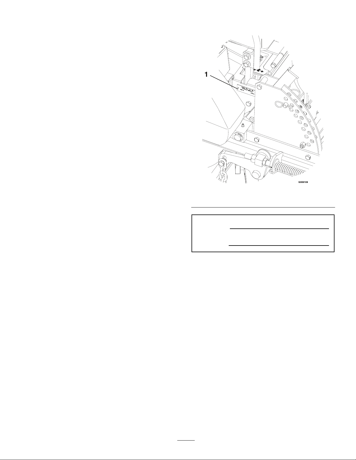
Figure1identiesthelocationofthemodelandserial
numbersontheproduct.Writethenumbersinthe
spaceprovided.
Figure1
1.Modelandserialnumberlocation
ModelNo.
SerialNo.
3
Page 4

Contents
Introduction...........................................................3
Safety.....................................................................5
SafetyAlertSymbol.........................................5
SafeOperatingPractices..................................5
SafetyandInstructionalDecals.....................10
Specications.......................................................16
ModelNumbers............................................16
Systems.........................................................16
Dimensions...................................................18
TorqueRequirements....................................18
ProductOverview................................................19
Operation.............................................................19
Controls........................................................19
Pre-Start........................................................21
OperatingInstructions..................................22
Transporting.................................................26
Maintenance.........................................................28
RecommendedMaintenanceSchedule(s)...........28
PeriodicMaintenance.......................................29
CheckEngineOilLevel.................................29
CheckBatteryCharge....................................29
CheckMowerBlades.....................................30
CheckSafetyInterlockSystem.......................30
CheckRolloverProtectionsSystems(Roll
Bar)Pins...................................................31
CheckSeatBelt..............................................31
CheckforLooseHardware............................31
ServiceAirCleaner........................................31
ChangeEngineOil........................................32
CheckHydraulicOilLevel.............................32
CheckTirePressures.....................................32
CheckConditionOfBelts..............................32
LubricateGreaseFittings...............................33
LubricateCasterWheelHubs........................33
LubricateBrakeHandlePivot........................34
LubricateBrakeRodBushings.......................34
LubricateMotionControlBronze
Bushings...................................................34
DrainFuelFilter/WaterSeparator..................34
ChangeFuelFilter/WaterSeparator...............35
ChangeHydraulicSystemFilter.....................35
WheelHub-SlottedNutTorque
Specication..............................................35
CheckEngineCoolantLevel..........................36
ChangeEngineCoolant.................................36
ThreadLockingAdhesives.............................37
MobilHTSGrease(OrFood-Grade
Anti-seize).................................................37
Copper-BasedAnti-seize..............................38
DielectricGrease...........................................38
Adjustments.....................................................38
DeckLeveling...............................................38
PumpDriveBeltTension...............................39
MuleDriveBeltTensionAdjustment.............39
DeckBeltTension........................................40
AlternatorBeltTension.................................40
BeltGuideAdjustment..................................40
BrakeLinkAdjustment..................................40
BrakeAdjustment..........................................41
ElectricClutchAdjustment............................41
ReverseIndicatorAdjustment........................41
MotionControlLinkageAdjustment.............42
MotionControlDamperAdjustment.............43
CasterPivotBearingsPre-Load
Adjustment...............................................43
ClutchShim..................................................43
Cleaning...........................................................46
CleanEngineCoolingSystem........................46
RemoveAccumulatedDebrisfromEngine
.................................................................46
CleaningoftheRadiator................................46
CleanDebrisFromMachine..........................46
CleanGrassBuild-UpUnderDeck................47
WasteDisposal..............................................47
Troubleshooting...................................................48
Schematics...........................................................51
4
Page 5
Safety
Safety
SafetyAlertSymbol
ThisSafetyAlertSymbol(Figure2)isusedbothin
thismanualandonthemachinetoidentifyimportant
safetymessageswhichmustbefollowedtoavoid
accidents
Thissymbolmeans:ATTENTION!BECOME
ALERT!YOURSAFETYISINVOLVED!
Figure2
1.Safetyalertsymbol
Thesafetyalertsymbolappearsaboveinformation
whichalertsyoutounsafeactionsorsituations
andwillbefollowedbythewordDANGER,
WARNING,orCAUTION.
•Neverletchildrenoruntrainedpeopleoperate
orservicetheequipment.Localregulationsmay
restricttheageoftheoperator.
•Theowner/usercanpreventandisresponsible
foraccidentsorinjuriesoccurringtohimselfor
herself,otherpeopleorproperty.
Preparation
•Evaluatetheterraintodeterminewhataccessories
andattachmentsareneededtoproperlyand
safelyperformthejob.Onlyuseaccessoriesand
attachmentsapprovedbyExmark.
•Wearappropriateclothingincludingsafetyglasses,
substantialfootwear,longtrousers,andhearing
protection.DoNotoperatewhenbarefootor
whenwearingopensandals.Longhair,loose
clothingorjewelrymaygettangledinmoving
parts.
CAUTION
DANGER:Whitelettering/Redbackground.
Indicatesanimminentlyhazardoussituationwhich,if
notavoided,Willresultindeathorseriousinjury.
WARNING:Blacklettering/Orangebackground.
Indicatesapotentiallyhazardoussituationwhich,if
notavoided,Couldresultindeathorseriousinjury.
CAUTION:Blacklettering/Yellowbackground.
Indicatesapotentiallyhazardoussituationwhich,if
notavoided,Mayresultinminorormoderateinjury.
Thismanualusestwootherwordstohighlight
information.Importantcallsattentiontospecial
mechanicalinformationandNoteemphasizes
generalinformationworthyofspecialattention.
SafeOperatingPractices
Training
•ReadtheOperator’sManualandothertraining
material.Iftheoperator(s)ormechanic(s)can
notreadEnglishitistheowner’sresponsibilityto
explainthismaterialtothem.
Thismachineproducessoundlevelsin
excessof85dBAattheoperator’searand
cancausehearinglossthroughextended
periodsofexposure.
Wearhearingprotectionwhenoperatingthis
machine.
•Inspecttheareawheretheequipmentistobe
usedandremoveallrocks,toys,sticks,wires,
bones,andotherforeignobjectswhichcanbe
thrownbythemachineandmaycausepersonal
injurytotheoperatororbystanders.
•Becomefamiliarwiththesafeoperationofthe
equipment,operatorcontrols,andsafetysigns.
•Alloperatorsandmechanicsshouldbetrained.
Theownerisresponsiblefortrainingtheusers.
5
Page 6

Safety
DANGER
Incertainconditionsdieselfuelisextremely
ammableandvaporsareexplosive.
Areorexplosionfromdieselfuelcanburn
you,others,andcausepropertydamage.
•Fillthefueltankoutdoorsinanopen
area,whentheengineiscold.Wipeup
anydieselfuelthatspills.
•Neverrellthefueltankordrainthe
machineindoorsorinsideanenclosed
trailer.
•DoNotllthefueltankcompletelyfull.
Adddieselfueltothefueltankuntilthe
levelis1/4to1/2inch(6–13mm)below
thebottomofthellerneck.Thisempty
spaceinthetankallowsdieselfuelto
expand.
•Neversmokewhenhandlingdieselfuel,
andstayawayfromanopenameor
wheredieselfuelfumesmaybeignited
byspark.
•Storedieselfuelinanapprovedcontainer
andkeepitoutofthereachofchildren.
•Addfuelbeforestartingtheengine.
Neverremovethecapofthefueltankor
addfuelwhenengineisrunningorwhen
theengineishot.
•Iffuelisspilled,DoNotattempttostart
theengine.Moveawayfromtheareaof
thespillandavoidcreatinganysourceof
ignitionuntilfuelvaporshavedissipated.
•DoNotoperatewithoutentireexhaust
systeminplaceandinproperworking
condition.
WARNING
Dieselfuelisharmfulorfatalifswallowed.
Long-termexposuretovaporshascaused
cancerinlaboratoryanimals.Failuretouse
cautionmaycauseseriousinjuryorillness.
•Avoidprolongedbreathingofvapors.
•Keepfaceawayfromnozzleanddiesel
tank/containeropening.
•Keepawayfromeyesandskin.
•Neversiphonbymouth.
•Checkthattheoperator’spresencecontrols,
safetyswitches,andshieldsareattachedand
functioningproperly .DoNotoperateunlessthey
arefunctioningproperly .
Operation
WARNING
Operatingengineparts,especiallythe
mufer,becomeextremelyhot.Severeburns
canoccuroncontactanddebris,suchas
leaves,grass,brush,etc.cancatchre.
•Allowengineparts,especiallythemufer,
tocoolbeforetouching.
•Removeaccumulateddebrisfrommufer
andenginearea.
•Installandmaintaininworkingordera
sparkarresterbeforeusingequipment
onforest-covered,grass-covered,or
brush-coveredunimprovedland.
WARNING
Engineexhaustcontainscarbonmonoxide,
whichisanodorlessdeadlypoisonthatcan
killyou.
DoNotrunengineindoorsorinasmall
connedareawheredangerouscarbon
monoxidefumescancollect.
•Operateonlyindaylightorgoodarticiallight,
keepingawayfromholesandhiddenhazards.
6
Page 7

Safety
•Besurealldrivesareinneutralandparkingbrake
isengagedbeforestartingengine.Useseatbelts
withtherollbarintheraisedandlockedposition.
•Neveroperatethemowerwithdamagedguards,
shields,orcovers.Alwayshavesafetyshields,
guards,switchesandotherdevicesinplaceandin
properworkingcondition.
•Nevermowwiththedischargedeectorraised,
removedoralteredunlessthereisagrass
collectionsystemormulchkitinplaceand
workingproperly.
•DoNotchangetheenginegovernorsettingor
overspeedtheengine.
•Stopengine,waitforallmovingpartstostop,
removekeyandengageparkingbrake:
–Beforechecking,cleaningorworkingonthe
mower.
–Afterstrikingaforeignobjectorabnormal
vibrationoccurs(inspectthemowerfor
damageandmakerepairsbeforerestarting
andoperatingthemower).
–Beforeclearingblockages.
–Wheneveryouleavethemower.
•Stopengine,waitforallmovingpartstostop,and
engageparkingbrake:
–Beforerefueling.
–Beforedumpingthegrasscatcher.
•Stoptheblades,slowdown,andusecautionwhen
crossingsurfacesotherthangrassandwhen
transportingthemowertoandfromtheareato
bemowed.
•Beawareofthemowerdischargepathanddirect
dischargeawayfromothers.
•DoNotoperatethemowerundertheinuence
ofalcoholordrugs.
•Useextremecarewhenloadingorunloadingthe
machineintoatrailerortruck.
•Usecarewhenapproachingblindcorners,shrubs,
trees,orotherobjectsthatmayobscurevision.
SlopeOperation
UseExtremecautionwhenmowingand/orturning
onslopesaslossoftractionand/ortip-overcould
occur.Theoperatorisresponsibleforsafeoperation
onslopes.
DANGER
Operatingonwetgrassorsteepslopescan
causeslidingandlossofcontrol.Wheels
droppingoveredges,ditches,steepbanks,or
watercancauserollovers,whichmayresult
inseriousinjury,deathordrowning.
•DoNotmowslopeswhengrassiswet.
•DoNotmowneardrop-offsornearwater.
WARNING
Hands,feet,hair,clothing,oraccessoriescan
becomeentangledinrotatingparts.Contact
withtherotatingpartscancausetraumatic
amputationorseverelacerations.
•DoNotoperatethemachinewithout
guards,shields,andsafetydevicesin
placeandworkingproperly.
•Keephands,feet,hair,jewelry,orclothing
awayfromrotatingparts.
•NEVERcarrypassengers.DONOToperate
themowerwhenpeople,especiallychildren,or
petsareinthearea.
•Bealert,slowdownandusecautionwhenmaking
turns.Lookbehindandtothesidebefore
changingdirections.
•DoNotmowslopesgreaterthan15
degrees.
•Reducespeedanduseextremecaution
onslopes.
•Avoidsuddenturnsorrapidspeed
changes.
•Keeptherollbarintheraisedandlocked
positionanduseseatbelt.
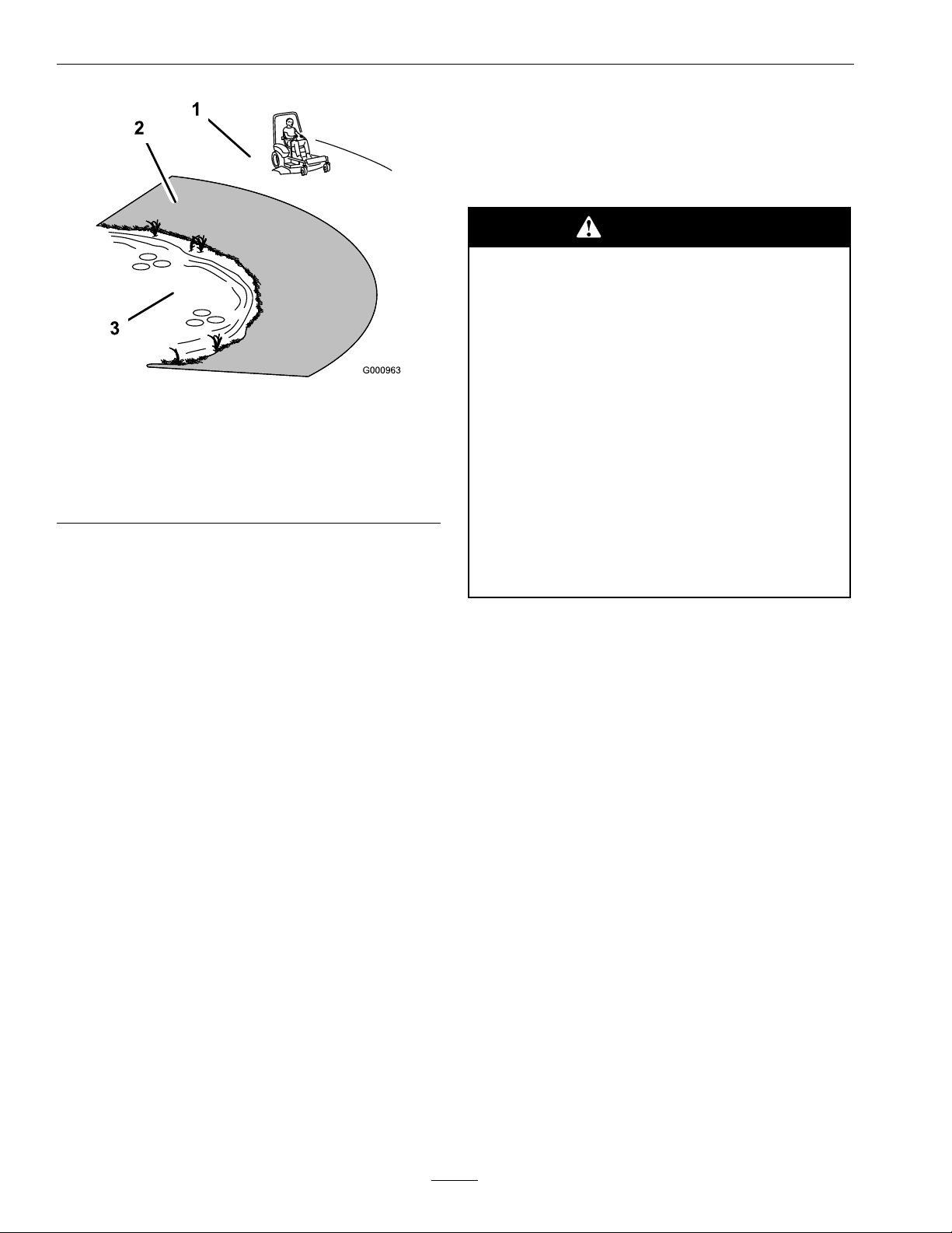
•Seeinsidethebackcovertodeterminethe
approximateslopeangleoftheareatobemowed.
•Useawalkbehindmowerand/orahandtrimmer
neardrop-offs,ditches,steepbanksorwater.
(Figure3).
7
Page 8
Safety
UsingtheRolloverProtectionSystem
(ROPS)
ARolloverProtectionSystem(rollbar)isinstalled
ontheunit.
WARNING
Thereisnorolloverprotectionwhentheroll
barisdown.Wheelsdroppingoveredges,
ditches,steepbanks,orwatercancause
rollovers,whichmayresultinseriousinjury,
deathordrowning.
Figure3
1.SafeZone-Usethemowerhereonslopeslessthan15
degrees
2.DangerZone-Useawalkbehindmowerand/orhand
trimmeronslopesgreaterthan15degrees,near
drop-offsandwater.
3.Water
•Removeormarkobstaclessuchasrocks,tree
limbs,etc.fromthemowingarea.Tallgrasscan
hideobstacles.
•Watchforditches,holes,rocks,dipsandrisesthat
changetheoperatingangle,asroughterraincould
overturnthemachine.
•Avoidsuddenstartswhenmowinguphillbecause
themowermaytipbackwards.
•Beawarethatoperatingonwetgrass,acrosssteep
slopesordownhillmaycausethemowertolose
traction.Lossoftractiontothedrivewheelsmay
resultinslidingandalossofbrakingandsteering.
•Alwaysavoidsuddenstartingorstoppingona
slope.Iftireslosetraction,disengagetheblades
andproceedslowlyofftheslope.
•Followthemanufacturer’srecommendationsfor
wheelweightsorcounterweightstoimprove
stability.
•Useextremecarewithgrasscatchersor
attachments.Thesecanchangethestabilityofthe
machineandcauselossofcontrol.
•Keeptherollbarintheraisedandlocked
positionanduseseatbelt.
•Lowertherollbaronlywhenabsolutely
necessary.
•DoNotwearseatbeltwhentherollbar
isdown.
•Driveslowlyandcarefully.
•Raisetherollbarassoonasclearance
permits.
•Checkcarefullyforoverheadclearances(i.e.
branches,doorways,andelectricalwires)before
drivingunderanyobjectsandDoNotcontact
them.
•Intheeventofarollover,taketheunittoan
AuthorizedServiceDealertohavetheROPS
inspected.
MaintenanceandStorage
•Disengagedrives,lowerimplement,setparking
brake,stopengineandremovekeyordisconnect
sparkplugwire.Waitforallmovementtostop
beforeadjusting,cleaningorrepairing.
•Keepengine,enginearea,andpumpdrivebelt
compartmentfreefromaccumulationofgrass,
leaves,excessivegreaseoroil,andotherdebris
whichcanaccumulateintheseareas.These
materialscanbecomecombustibleandmayresult
inare.
•Letenginecoolbeforestoringanddonotstore
nearameoranyenclosedareawhereopenpilot
lightsorheatappliancesarepresent.
•Shutofffuelwhilestoringortransporting.Do
Notstorefuelnearamesordrainindoors.
8
Page 9

Safety
•Parkmachineonlevelground.Neverallow
untrainedpersonneltoservicemachine.
•Usejackstandstosupportcomponentswhen
required.
•Carefullyreleasepressurefromcomponentswith
storedenergy.
•Disconnectbatteryorremovesparkplugwire
beforemakinganyrepairs.Disconnectthe
negativeterminalrstandthepositivelast.
Reconnectpositiverstandnegativelast.
•Usecarewhencheckingblades.Wraptheblade(s)
orweargloves,andusecautionwhenservicing
them.Onlyreplacedamagedblades.Never
straightenorweldthem.
•Keephandsandfeetawayfrommovingparts.
Ifpossible,donotmakeadjustmentswiththe
enginerunning.
•Chargebatteriesinanopenwellventilatedarea,
awayfromsparkandames.Unplugcharger
beforeconnectingordisconnectingfrombattery.
Wearprotectiveclothinganduseinsulatedtools.
•Keepallguards,shieldsandallsafetydevicesin
placeandinsafeworkingcondition.
WARNING
Hydraulicuidescapingunderpressure
canpenetrateskinandcauseinjury.Fluid
accidentallyinjectedintotheskinmustbe
surgicallyremovedwithinafewhoursbya
doctorfamiliarwiththisformofinjuryor
gangrenemayresult.
•Makesureallhydraulicuidhoses
andlinesareingoodconditionand
allhydraulicconnectionsandttings
aretightbeforeapplyingpressureto
hydraulicsystem.
•Keepbodyandhandsawayfrompinhole
leaksornozzlesthatejecthighpressure
hydraulicuid.
•Usecardboardorpaper,notyourhands,
tondhydraulicleaks.
•Safelyrelieveallpressureinthehydraulic
systembyplacingthemotioncontrol
leversinneutralandshuttingoffthe
enginebeforeperforminganyworkon
thehydraulicsystem.
•Checkallboltsfrequentlytomaintainproper
tightness.
•Frequentlycheckforwornordeteriorating
componentsthatcouldcreateahazard.
•Allreplacementpartsmustbethesameas
orequivalenttothepartssuppliedasoriginal
equipment.
WARNING
Fuelsystemcomponentsareunderhigh
pressure.Theuseofimpropercomponents
canresultinsystemfailure,fuelleakageand
possibleexplosion.
Useonlyapprovedfuellinesandclampsfor
highpressuresystems.
9
Page 10

Safety
SafetyandInstructionalDecals
•Keepallsafetysignslegible.Removeallgrease,
dirtanddebrisfromsafetysignsandinstructional
labels.
•Replaceallworn,damaged,ormissingsafety
signs.
•Whenreplacementcomponentsareinstalled,be
surethatcurrentsafetysignsareafxedtothe
replacedcomponents.
•Ifanattachmentoraccessoryhasbeeninstalled,
makesurecurrentsafetysignsarevisible.
1-303508
•Newsafetysignsmaybeobtainedfrom
yourauthorizedExmarkequipmentdealeror
distributororfromExmarkMfg.Co.Inc.
•Safetysignsmaybeafxedbypeelingoffthe
backingtoexposetheadhesivesurface.Apply
onlytoaclean,drysurface.Smoothtoremove
anyairbubbles.
•Familiarizeyourselfwiththefollowingsafetysigns
andinstructionlabels.Theyarecriticaltothesafe
operationofyourExmarkcommercialmower.
1-633706
1-403005
1-513742
98-5954
1-513748
10
Page 11
Safety
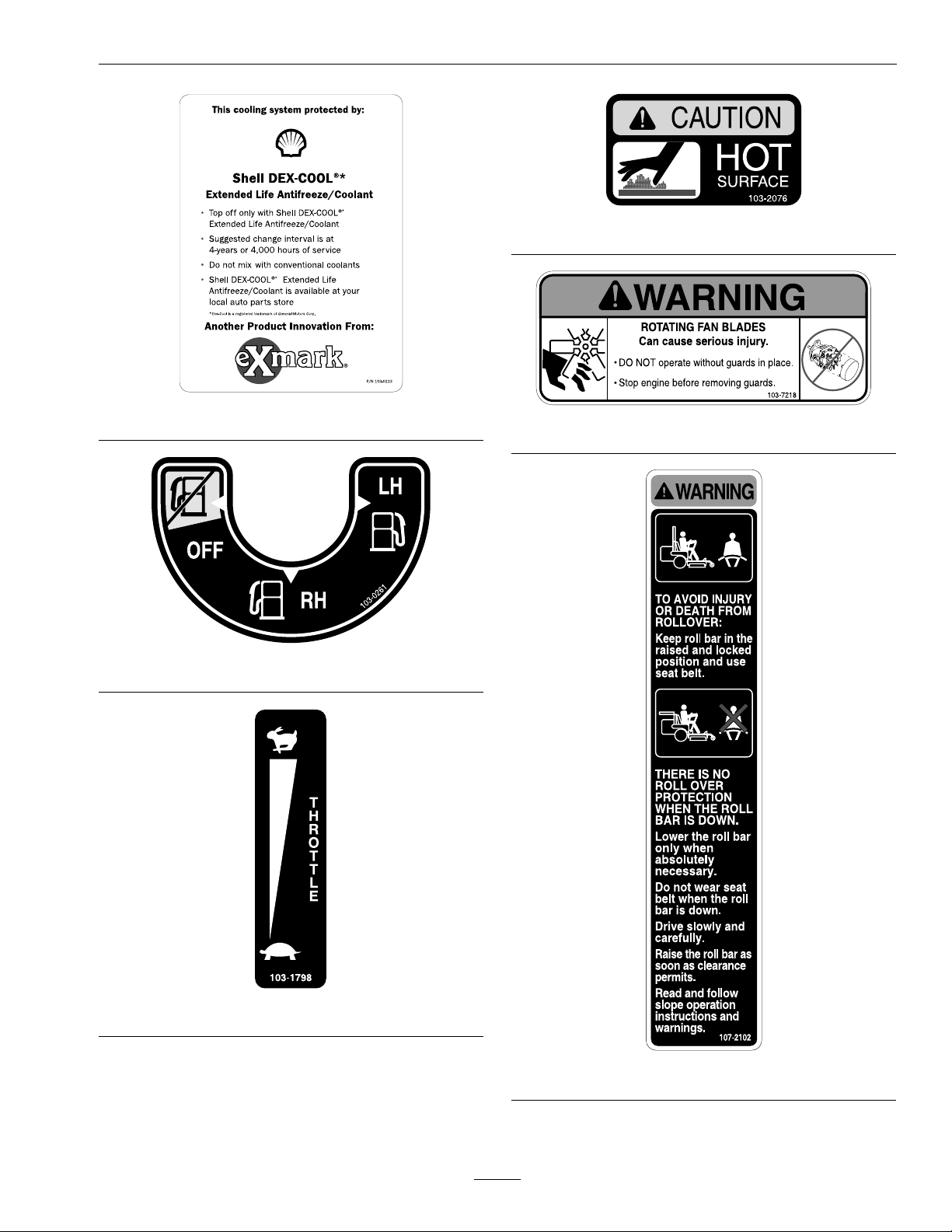
103-2076
103-0223
103-0261
103-7218
103-1798
107-2102
11
Page 12
Safety
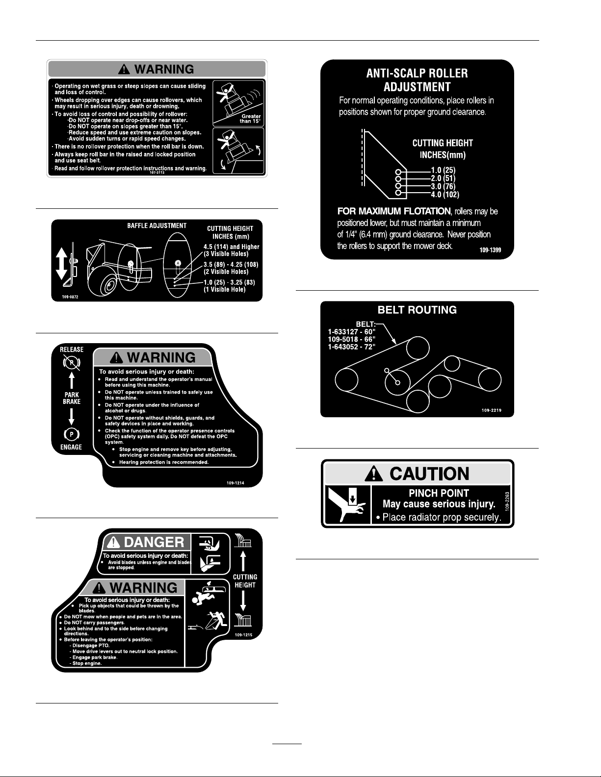
107-2112
109-1399
109-0872
109-2219
109-1214
109-2263
109-1215
12
Page 13
Safety
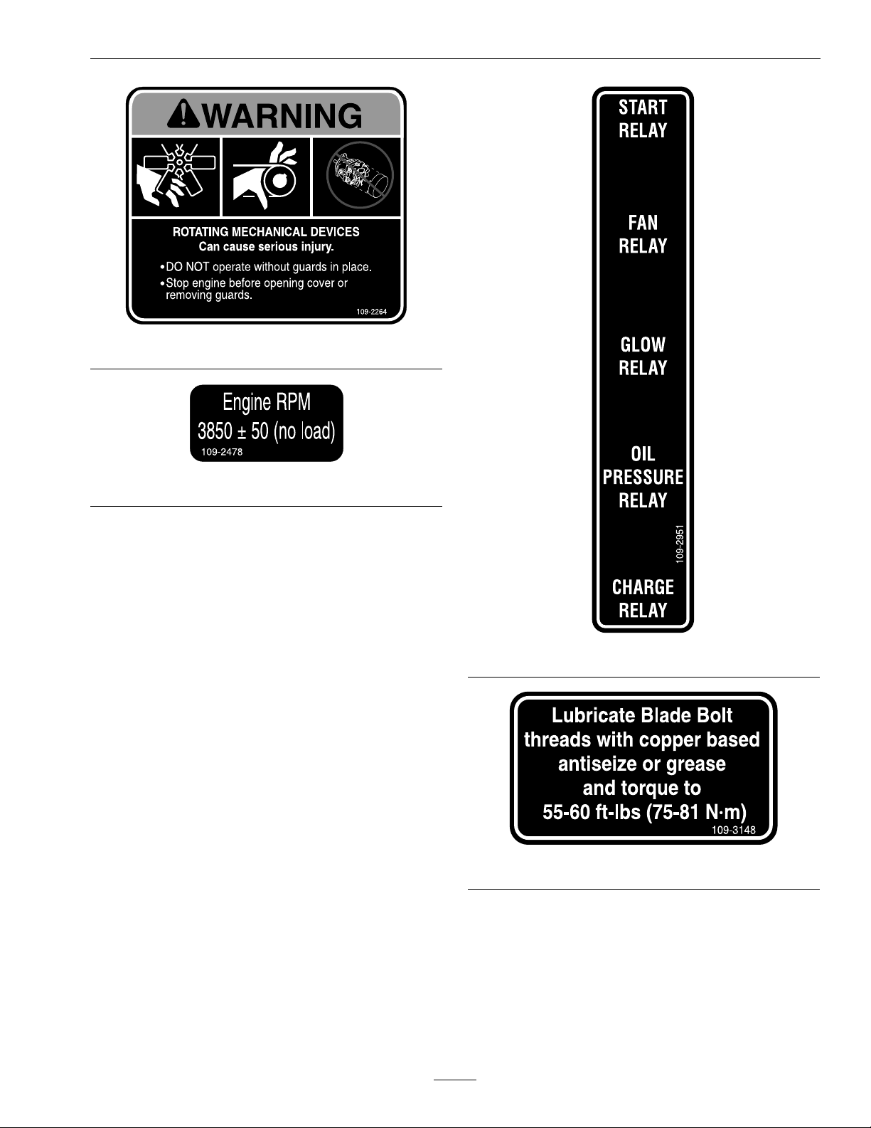
109-2264
109-2478
109-2951
109-3148
13
Page 14
Safety
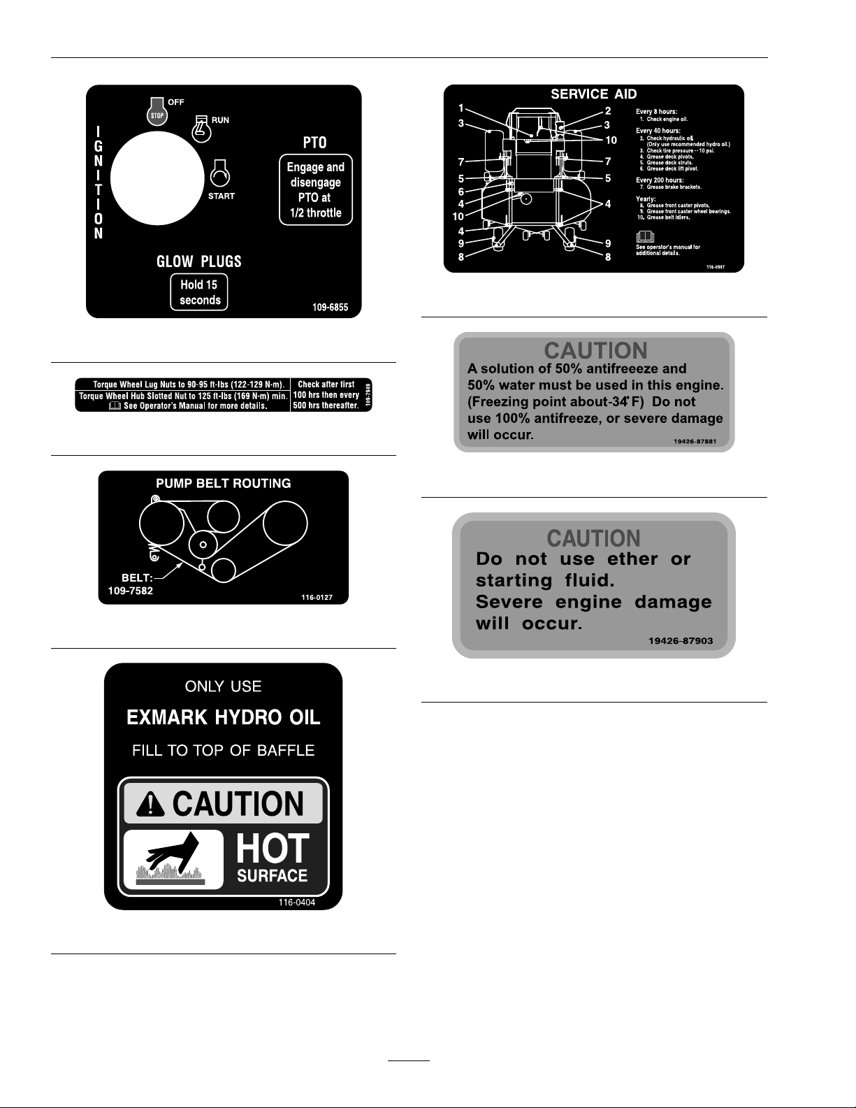
116-0997
109-6855
109-7949
19426-87881
116-0127
19426-87903
116-0404
14
Page 15

Safety
107-9866
1.Fast
2.Slow
3.Neutral4.Reverse
15
Page 16

Specications
Specications
ModelNumbers
SerialNos:790,000andHigher
LXS25KD605;LXS25KD665;LXS25KD725
Systems
Engine
•EngineSpecications:SeeyourEngineOwner’s
Manual
•RPM:FullSpeed:3850±50RPM(NoLoad)
Idle:1400RPM
FuelSystem
•Capacity:15.5gal.(58.6L)
•TypeofFuel:Dieselfuel,40cetaneorhigheror
biodieseluptoB20(20%biodiesel,80%petro
diesel).
•FuelFilter:In-line113Micron
ExmarkP/N112-7836.
•FuelShut-OffValve:1/4turnincrements
(“OFF”,righttank,lefttank,)
•Fuelgaugeinlefthandfueltank.
ElectricalSystem
•ChargingSystem:ExternalAlternator
•ChargingCapacity:60amps
•BatteryType:BCIGroup26
•BatteryVoltage:12Volt
•Polarity:NegativeGround
•Fuses:One20ampbladetype;One30ampblade
type
SafetyInterlockSystem
•OperatormustbeinseatwhenPTOisengaged,
brakeisdisengaged,ormotioncontrolleversare
movedinorenginewillstop.
•Enginewillstopifeithertheleft,theright,or
bothleversaremovedfromneutrallockposition
whilebrakeisengaged.
CoolingSystem
•Fan:Electricwithcontinuousoperationwith
enginerunning.
•CoolantLiquid:50/50mixofDexCool©
extendedlifeantifreezeandwater.
•CoolantCapacity:4quarts
OperatorControls
•SteeringandMotionControl:
Note:Motioncontrolleversareadjustableto
twoheights.
–Separatelevers,oneachsideoftheconsole,
controlspeedanddirectionoftravelofthe
respectivedrivewheels.
–Steeringiscontrolledbyvaryingtheposition
oftheleversrelativetoeachother.
–Movingmotioncontrolleversoutward(in
slots)locksthedrivesysteminneutral.
•PTOEngagementSwitch:Engageselectricclutch
(todrivebelt)whichengagesmowerblades.
•ParkingBrakeLever:Engagesparkingbrake.
•DeckHeightAdjustmentLever:Setscutting
heighttodesiredposition.
•DeckLiftAssistLever:Footpedalthatassists
inraisingthedeck.
•PTOmustbedisengaged,brakeengaged,and
motioncontrolleversout(neutrallock)tostart
engine.(Itisnotnecessaryfortheoperatortobe
intheseattostarttheengine.)
Seat
•Type:Deluxesuspensionseathighback,low
prolefoam-in-placecushion(dampened,
adjustablespringsuspension)andarmrests,
adjustablebackangle.
16
Page 17

Specications
•Mounting:Hingedtotiltupforaccessto
hydraulicpumps,batteryandothercomponents.
Heldintiltedpositionwithscissor—typelinks.
Adjustableforeandaftseattrack.
•Armrests:Moldedadjustableip-uparmrests.
•SeatSafetySwitch:Incorporatedintothe
SafetyInterlockSystem.Timedelayseatswitch
eliminatesroughgroundcut-outs.
HydrostaticGroundDriveSystem
•HydrostaticPumps:TwoHydroGearPW
variabledisplacementpistonpumps.
•WheelMotors:TwoParker/Rosswith11/4inch
taperedshafts.
•HydraulicOilType:ExmarkPremiumHydrooil.
•HydraulicOilCapacity:5.5qt.(5.2L)
•HydraulicFilter:Replaceablecartridgetype.
P/N103-2146:25microns,Nobypass
•Speeds:
–0-12.0mph(19.3km/hr)forward.
•Discharge:Side
•BladeSize:(3ea.)
–60inchDeck:20.75inches(52.7cm)
–66inchDeck:22.75inches(57.8cm)
–72inchDeck:24.75inches(62.9cm)
•BladeSpindles:Solidsteelspindleswith1.18inch
(30mm)I.D .bearings.
•DeckDrive:
–Electricclutchmountedonhorizontalengine
shaft.“B”Sectionbelt(withself-tensioning
idler)fromelectricclutchtotransfershaft
mountedondeck.
–Bladesaredrivenbyone“B”Sectionbelt
(w/self-tensioningidler)fromtransfershaft
ondecktobladespindles.
•Deck:
Fulloatingdeckisattachedtoout-frontsupport
frame.Sixanti-scalprollersprovidemaximum
turfprotection.Deckdesignallowsforbagging,
mulchingorsidedischarge.
–0-8.0mph(12.9km/hr)reverse.
•Drivewheelreleasevalvesallowmachinetobe
movedwhenengineisnotrunning.
Tires&Wheels
DriveFrontCaster
Pneumatic
(Air-Filled)
DeckSize
Quantity
TreadSize
Size26x12.00-1213x6.50-6
PlyRating
Pressure
60,66,&72
22
“Multi-Trac
C/S”
4
10psi(69kPa)
Semi-Pneumatic
AllDecks
Smooth
CuttingDeck
•CuttingWidth:
•DeckDepth:
–60inchDeck:6.0inches(15.2cm)
–66inchDeck:6.0inches(15.2cm)
–72inchDeck:6.0inches(15.2cm)
•CuttingHeightAdjustment:
Anextra-longcushionedleverisusedtoadjust
thecuttingheightfrom1inch(2.5cm)to5inches
(12.7cm)in1/4inch(6.4mm)increments.The
cuttingheightadjustmenthandlehasatransport
positionandalladjustmentscanbemadewhile
theoperatorremainsseated.Unitsalsohavea
footoperateddeckliftassistlevertoaidinraising
thedeck.
•MulchingKit:Optional.
–60inch(152.4cm)
–66inch(167.6cm)
–72inch(182.9cm)
17
Page 18

Specications
Dimensions
OverallWidth:
Without
Deck
Deector
Up
Deector
Down
OverallLength:
RollBarUp
RollBarDown
60inch
Deck
53.5inches
(135.9cm)
61.4inches
(156.0cm)
72.8inches
(184.9cm)
60inch
Deck
81.9inches
(208.0cm)
92.5inches
(235.0cm)
66inch
Deck
57.3inches
(145.5cm)
68.0inches
(172.7cm)
79.4inches
(201.7cm)
66inch
Deck
83.4inches
(211.8cm)
94.0inches
(238.8cm)
72inch
Deck
61.5inches
(156.2cm)
74.3inches
(188.7cm)
85.8inches
(217.9cm)
72inch
Deck
85.8inches
(217.9cm)
96.4inches
(244.9cm)
TorqueRequirements
BoltLocation
BladeDriveSheave
MountingNut
CutterHousingSpindle
Nut
BladeMountingBolt
(lubricatewithanti-seize)
EngineDeck/FrontFrame
MountBolts
Anti-ScalpRollerNyloc
NutSeeFigure10
Anti-ScalpRollerHex
CapscrewSeeFigure10
EngineMountingBolts
WheelLugNuts
WheelMotorMounting
Bolts
WheelHubSlottedNutminimum125ft-lb
Torque
90-110ft-lb(122-149N-m)
160-185ft-lb(217-251
N-m)
55-60ft-lb(75-81N-m)
30-35ft-lb(41-47N-m)
30-35ft-lb(41-47N-m)
50-55ft-lb(68-75N-m)
15-20ft-lb(20-27N-m)
90-95ft-lb(122-129N-m)
72-77ft-lb(98-104N-m)
(169N-m)
OverallHeight:
RollBar-UpRollBar-Down
72.7inches(184.7cm)53.8inches(136.7cm)
TreadWidth:(CentertoCenterof
Tires,Widthwise)
Drive
Wheels
Caster
Wheels
60inch
Deck
41.9inches
(106.4cm)
37.3inches
(94.7cm)
66inch
Deck
45.9inches
(116.6cm)
42.3inches
(107.4cm)
72inch
Deck
45.9inches
(116.6cm)
47.3inches
(120.1cm)
WheelBase:(CenterofCasterTireto
CenterofDriveTire)
60inchDeck66inchDeck72inchDeck
56.0inches
(142.2cm)
57.6inches
(146.3cm)
60.2inches
(152.9cm)
RolloverProtectionSystem
(RollBar)MountingBolts
DeckDriveJackshaftNut
ClutchRetainingBolt
(securedwiththreadlocker)
30-35ft-lb(41-47N-m)
75-80ft-lb(102-108N-m)
55-60ft-lb(75-81N-m)
CurbWeight:
60inchDeck66inchDeck72inchDeck
1545lb(701kg)1595lb(723kg)1645lb(746kg)
18
Page 19

Operation
ProductOverview
1.MotionControlLever5.Controls
2.ParkingBrakeLever
3.Height-of-CutLever
4.FuelCap(BothSides)
Figure4
6.SeatBelt
7.RollBar
Operation
Note:Determinetheleftandrightsidesofthe
machinefromthenormaloperatingposition.
Controls
MotionControlLevers
Themotioncontrolleverslocatedoneachsideofthe
consolecontroltheforwardandreversemotionof
themachine.Theleverscontroltheowofhydraulic
oilfromthehydrostaticpumptothedrivewheel
motorforeachside.
Movingtheleversforwardorbackwardturnsthe
wheelonthesamesideforwardorinreverse.Wheel
speedisproportionaltotheamounttheleveris
moved.
Movingtheleversoutwardfromthecenterposition
intotheT-slotlocksthemintheneutralposition
(Figure6).
ThrottleControl
Locatedonrightfueltank.
Thethrottleisusedtocontrolenginespeed.Moving
thethrottleleverforwardwillincreaseenginespeed
andmovingthethrottlelevertotherearwilldecrease
enginespeed.Movingthethrottleforwardintothe
detentisfullthrottle.
BrakeLever
Locatedonleftsideofunit,justtothefrontofthe
console.
Thebrakeleverengagesaparkingbrakeonthedrive
wheels.
Pulltheleverupandrearwardtoengagethebrake.
Pushtheleverforwardanddowntodisengagethe
brake.
Theunitmustbetieddownandbrakeengagedwhen
transporting.
IgnitionSwitch
Locatedonrightfueltank.
Theignitionswitchisusedtostartandstopthe
engine.Theswitchhasthreepositions“OFF”,“ON”
19
Page 20

Operation
and“START”.Insertkeyintoswitchandrotate
clockwisetothe“ON”position.Rotateclockwiseto
thenextpositiontoengagethestarter(keymustbe
heldagainstspringpressureinthisposition).
Note:Brakemustbeengaged,motioncontrollevers
out(neutrallockposition)andPTOswitch“OFF”to
startengine.(Itisnotnecessaryfortheoperatorto
beintheseattostarttheengine.)
HourMeter
Locatedontherightfueltank.
Thehourmeterisconnectedtoapressureswitch
installedintheengineblockanditrecordsthe
numberofhoursthattheenginehasrun.Ifthe
ignitionswitchisleftonwithoutenginerunning,
hourmeterwillnotrun.
Note:Thisswitchisnotalowoilsensorandwillnot
alerttheoperatoriftheengineoilislow .
FuelShut-OffValve
Locateddirectlybelowtherightsideofconsole,next
tothecubby.
Thefuelshut-offvalveisusedtoshutoffthefuel
whenthemachinewillnotbeusedforafewdays,
duringtransporttoandfromthejobsite,andwhen
parkedinsideabuilding.
Thevalvehasthreepositions,eachpositionmade
in1/4turnincrements.
FuelFlowValveHandlePosition
“Off”Right
RightTank
LeftTankLeft
Down
Drivewheelreleasevalvesareusedtoreleasethe
hydrostaticdrivesystemtoallowthemachinetobe
pushedwithouttheenginerunning.Unhookseat
latchandtiltseatuptogainaccesstopumps.
Witha5/8inchwrench,turnbothvalvesoneturn
counterclockwisetoreleasedrivesystem.Turn
clockwisetoresetsystem.DoNotovertighten.Do
Nottowmachine.
TrackingAdjustmentKnob
LocatedundertheseatontheLHpumpcontrollink.
Rotatingthisknoballowsnetuningadjustmentsso
thatthemachinetracksstraightwiththedrivelevers
inthefullforwardposition.
Stopmachineandwaitforallmovingpartstostop.
Engageparkbrake.Unhookseatlatchandtiltseat
forwardtogainaccesstothetrackingknob.Rotate
theknobclockwise(asviewedfromtherearofthe
machine)tocausethemachinetotrackmoretothe
rightandcounterclockwisetocausethemachine
totrackmoretotheleft.Adjustinquarter-turn
incrementsuntilthemachinetracksstraight.Check
thatthemachinedoesnotcreepwheninneutralwith
theparkbrakedisengaged.
Important:DoNotrotatetheknobtoofar,as
thismaycausethemachinetocreepinneutral.
RefertotheMotionControlLinkageAdjustment
sectioninMaintenance.
PTOEngagementSwitch
Locatedonrightfueltank.
Switchmustbepulledouttothe“ROTATE”
positiontoengagetheblades.Switchispushedinto
the“STOP”positiontostoptheblades.
FuelGauge
Locatedontheleftfueltank.
Thefuelgaugemonitorstheamountoffuelintheleft
tankonly.Usethefuelfromtherightfueltankrst.
Whentherightfueltankisempty,switchtotheleft
fueltank.Fuelgaugewillmonitortheremainingfuel.
DriveWheelReleaseValves
Locatedonthetoprightfrontcornerofhydrostatic
pumps.
CoolantTemperatureGauge
Locatedatthefrontoftheleftfueltank.
Thecoolanttemperaturegaugemonitorsthe
temperatureoftheenginecoolant.Anengine
overheatingconditionisindicatedbytheredarea
onthegaugeandanalarmwillsound.Refertothe
WarningBuzzerintheTroubleshootingsection.
Voltmeter
LocatednexttotheCoolantTemperatureGaugeat
thefrontoftheleftfueltank.
20
Page 21

Operation
Thevoltmetermeasurethevoltageoutputofthe
alternator.Bothhighandlowvoltageswillpotentially
damagethebattery.
GlowPlugSwitchandLight
Locatedontherightfueltank.
Depressandholdtheswitchtoheattheglowplugs.
Theglowpluglightcomesonwhentheglowplug
switchisdepressed.Theglowpluglightindicatesthe
glowplugsarepreheatingthecombustionchamber.
LowOilPressureLight
Locatedontherightfueltank.
Lightwillcomeonwhenengineoilpressureislow
orlost.
WarningBuzzer
Locatedbehindtheseatundertheairdeectoron
theelectricalpanel.
Thebuzzerisawarningsignalthattheengine
isoverheatingortheoilpressureislow .Seethe
Troubleshootingsection.
Useofsummergradedieselfuelabove20°F(-7°C)
willcontributetowardlongerlifeofthepump
components.
Important:DoNotusekeroseneorgasoline
insteadofdieselfuel.Failuretoobservethis
cautionwilldamagetheengine.
BiodieselReady
Thismachinecanalsouseabiodieselblendedfuel
ofuptoB20(20%biodiesel,80%petrodiesel).The
petrodieselportionshouldbeloworultralowsulfur.
Observethefollowingprecautions:
•Thebiodieselportionofthefuelmeet
specicationASTMD6751orEN14214.
•Theblendedfuelcompositionshouldmeet
ASTMD975orEN590.
•Paintedsurfacesmaybedamagedbybiodiesel
blends.
•UseB5(biodieselcontendof5%)orlesserblend
incoldweather.
•Monitorseals,hoses,gasketsincontactwithfuel
astheymaybedegradeovertime.
Pre-Start
Makesureyouunderstandthecontrols,their
locations,theirfunctions,andtheirsafety
requirements.
RefertotheMaintenancesectionandperformallthe
necessaryinspectionandmaintenancesteps.
DeterminingFuel
Theenginerunsonclean,freshdieselfuelwith
aminimumoctaneratingof40.Purchasefuelin
quantitiesthatcanbeusedwithin30daystoensure
fuelfreshness.
Usesummergradedieselfuel(No.2-D)at
temperaturesabove20°F(-7°C)andwintergrade
dieselfuel(No.1-DorNo.1-D/2-Dblend)below
20°F(-7°C).Useofwintergradedieselfuelatlower
temperaturesprovideslowerashpointandpour
pointcharacteristics,thereforeeasingstartabilityand
lesseningchancesofchemicalseparationofthefuel
duetolowertemperatures(waxappearance,which
maypluglters).
•Fuellterpluggingmaybeexpectedforatime
afterconvertingtobiodieselblends.
•Contactyourdistributorifyouwishformore
informationonbiodiesel.
FillingtheFuelTank
1.Shuttheengineoffandsettheparkingbrake.
2.Cleanaroundeachfueltankcapandremovethe
cap.Addfueltobothfueltanks,untilthelevelis
1/4to1/2inch(6to13mm)belowthebottom
ofthellerneck.Thisspaceinthetankallows
thefueltoexpand.DoNotllthefueltanks
completelyfull.
3.Installfueltankcapssecurely.Wipeupanyfuel
thatmayhavespilled.
4.Ifpossible,llthefueltankaftereachuse.This
willminimizepossiblebuildupofcondensation
insidethefueltank.
21
Page 22

Operation
OperatingInstructions
RaisetheRolloverProtectionSystem
(ROPS)
Important:Lowertherollbaronlywhen
absolutelynecessary.
1.Removethehairpincotterpinsandremovethe
tworollbarpins(Figure5).
2.Raisetherollbartotheuprightpositionand
installthetwopinsandsecurethemwiththe
hairpincotterpins(Figure5).
Important:Alwaysusetheseatbeltwiththe
rollbarintheraisedposition.Ensurethatthe
rearpartoftheseatissecuredwiththeseat
latch.
2.Pullupandbackontheparkingbrakeleverto
engagetheparkingbrake.
3.PushinonthePTOswitchtothe“STOP”
position.
Note:Itisnotnecessaryfortheoperatortobe
intheseattostarttheengine.
4.Onawarmengine,placethethrottleinthe
“SLOW”position.
5.Onacoldengine,(below14°F(-10°C)),placethe
throttleinthe“MIDWAY”position.
Note:DoNotusefuelleftoverfromsummer.
6.Turnignitionswitchtothe“ON”position.
Depresstheglowplugswitchandtheglowplug
lightwillturnon.Holdswitchasrequiredby
chartbelow.Turntheignitionswitchtothe
“START”position.Releasetheignitionswitchas
soonastheenginestarts.
GlowPlugChart
Figure5
1.Rollbar3.Pin
2.Raisedposition4.Hairpincotterpin
OpentheFuelShut-OffValve
TurnthevalvetotheLHorRHtank.
AmbientTemperature
Above50°F(10°C)
50°F(10°C)to23°F(-5°C)
Below23°F(-5°C)
Limitofcontinuoususe
HoldGlowPlugsOn
NONEED
Approximately5seconds
Approximately10seconds
20seconds
Theglowpluglight,locatedneartheglow
plugswitch,willilluminatewhentheswitchis
depressed.Theglowpluglightindicatestheglow
plugsarepreheatingthecombustionchamber.
Important:DoNotcranktheengine
continuouslyformorethentensecondsata
time.Iftheenginedoesnotstart,allowa30
secondcool-downperiodbetweenstarting
attempts.Failuretofollowtheseguidelines
canburnoutthestartermotorand/orfuel
solenoid.
7.Movethethrottletothe“SLOW”(ifin
“MIDWAY”)andlettheenginewarmupafew
minutesbeforemovingthethrottletothe“FAST”
position.
StartingtheEngine
1.Movethemotioncontrolleversouttotheneutral
lockposition.
22
Page 23

Operation
EngagingthePTO
DANGER
Therotatingbladesunderthemowerdeck
aredangerous.Bladecontactcancause
seriousinjuryorkillyou.
DoNotputhandsorfeetunderthemower
ormowerdeckwhenthebladesareengaged.
DANGER
Anuncovereddischargeopeningwillallow
objectstobethrowninanoperator’sor
bystander’sdirection.Also,contactwiththe
bladecouldoccur.Thrownobjectsorblade
contactcancauseseriousinjuryordeath.
Neveroperatethemowerwiththedischarge
deectorraised,removed,oralteredunless
thereisagrasscollectionsystemormulch
kitinplaceandworkingproperly.
ThePTOpush-pullswitchengagesthecuttingblades.
Besurethatallpersonsareclearofthemowerdeck
anddischargeareabeforeengagingPTO.
5.Placethethrottlemidwaybetweenthe“SLOW”
and“FAST”positions.
6.Allowtheenginetorunforaminimumof15
seconds,thenturntheignitionswitchtothe
“OFF”positiontostoptheengine.
7.Removethekeytopreventchildrenorother
unauthorizedpersonsfromstartingengine.
8.Closethefuelshut-offvalvewhenthemachine
willnotbeinuseforafewdays,when
transporting,orwhentheunitisparkedinside
abuilding.
DrivingtheMachine
CAUTION
Machinecanspinveryrapidlybypositioning
onelevertoomuchaheadoftheother.
Operatormaylosecontrolofthemachine,
whichmaycausedamagetothemachine
orinjury.
•Usecautionwhenmakingturns.
•Slowthemachinedownbeforemaking
sharpturns.
Important:Operatormustbeinseatbeforethe
PTOcanbeengaged.
1.Setthethrottletothe“MIDWAY”position.
2.PullthePTOswitchoutwardtothe“ROTATE”
position.
3.Placethethrottleinthe“FAST”positiontobegin
mowing.
DisengagingthePTO
1.Setthethrottletothe“MIDWAY”position.
2.PushthePTOswitchintothe“STOP”position
todisengagetheblades.
StoppingtheEngine
1.Bringtheunittoafullstop.
2.DisengagethePTO.
3.Movethemotioncontrolleversouttotheneutral
lockposition.
Important:Tobeginmovement(forwardor
backward)theoperatormustbeintheseat,the
brakelevermustbedisengaged(pusheddown)
beforethemotioncontrolleverscanbemovedin
ortheenginewillstop.
WhenleversarecenteredintheT-slotthedrive
systemisintheneutralposition.Withleversmoved
outintheT-slotthedrivesystemisintheneutrallock
position(Figure6).
4.Engagetheparkingbrake.
23
Page 24

Operation
Figure6
1.HandlesOut(Neutral
Lock)
2.HandlesIn(Neutral)
3.FrontofUnit
4.Forward
DrivingForward
1.Releasetheparkingbrake.
2.Movethemotioncontrolleversinwardtothe
centertotheneutralunlockedposition.
3.Tomoveforwardinastraightlineapplyequal
forwardpressuretobothlevers.
Toturnleftorright,pullthemotioncontrollever
backtowardneutralinthedirectiondesired.
Themachinewillmovefasterthefartherthe
motioncontrolleversaremovedawayfrom
neutral.
4.Tostop,pullthemotioncontrolleversbackto
theneutralposition.
5.Neutral
6.Reverse
7.NeutralLock
Figure7
1.HandlesOut(Neutral
Lock)
2.HandlesIn(Neutral)
3.FrontofUnit
4.Forward
5.Reverse
DrivinginReverse
1.Movethemotioncontrolleversinwardtothe
centertotheneutralunlockedposition.
2.Tomoverearwardinastraightlineapplyingequal
pressurepullbothmotioncontrolleversrearward.
Toturnleftorright,releasepressureonthe
motioncontrollevertowardthedirectiondesired.
3.Tostop,pushthemotioncontrolleverstothe
neutralposition.
AdjustingtheCuttingHeight
Thecuttingheightofthemowerdeckisadjusted
from1to5inches(2.54cmto12.7cm)in1/4inch
(6.4mm)increments.
1.Stopthemachineandmovethemotioncontrol
leversoutwardtotheneutrallockedposition.
2.DisengagethePTO.
3.Raisethedeckheightlevertothetransport
position(alsothe5inch(12.7cm)cuttingheight
position)(Figure8).
Thedeckcanberaisedbypullingthedecklever
upand/orbypushingdownonthefootoperated
24
Page 25

Operation
deckliftassistleverlocatedatthefrontright
corneroftheoorpan.
Note:Whenchangingthecuttingheight
positions,alwayscometoacompletestop
anddisengagethePTO.
Figure8
1.Leverintransportand5inch(12.7cm)cuttingheight
position
4.Inserttheheightadjustmentpinintothehole
correspondingtothedesiredcuttingheightand
installthehairpincotterpin.
Seethedecalonthesideofthedeckliftplatefor
cutheights.
5.Movethedeckheightleveroutofthetransport
position(or5inch(12.7cm)cuttingheight)and
downontotheheightadjustmentpintomowat
selectedheight.
Note:Thefootoperateddeckliftassistlever
canbeusedtomomentarilyliftthedecktoclear
objects.BesurethatPTOisdisengaged.
6.Placetherollersinoneofthepositionsshown
(Figure9).Rollerswillmaintain3/4inch(19mm)
clearancetothegroundtominimizegougingand
rollerwearordamage.
Figure9
Forcuttingheightsabove4.0inches(102mm)usethe
bottomhole.Therollerswillstillbeeffectiveagainst
scalping.
1.Anti-scalproller
mountingbracket
2.Cuttingheight
ForMaximumDeckFlotation,placetherollers
oneholepositionlower.Rollersshouldmaintain
1/4inch(6.4mm)clearancetotheground.Do
Notadjusttherollerstosupportthedeck.
7.Besuretherollerboltsareinstalledwiththe
springdiscwasherbetweentheheadofthebolt
andthemountingbracket.
Note:Thefootoperateddeckliftassistlever
canbeusedtomomentarilyliftthedecktoclear
objects.BesurethatPTOisdisengaged.
8.Torquethe3/8–24x2Gr8hexcapscrewto
50–55ft-lb(68–75N-m)(Figure10).
AdjustingtheAnti-ScalpRollers
Itisrecommendedtochangetheanti-scalproller
positionwhentheheightofcuthaschanged.
1.Stopthemachineandmovethemotioncontrol
leversoutwardtotheneutrallockedposition.
2.DisengagethePTO.
3.Engagetheparkbrake.
4.Stoptheengine,removethekeyandwaitforall
movingpartstostop.
5.Afteradjustingtheheightofcut,adjustthe
anti-scalprollersbyremovingtheboltandspring
discwasher.
25
Page 26

Operation
Figure10
1.Springdiscwasher
(conetowardsbolthead)
2.Frontrightanti-scalp
bracketshown
9.Ifthe3/8nylocnuthasbeenremoved,
re-installandtorqueto30–35ft-lb(41–47N-m)
(Figure10).
3.3/8nyloc-torqueto30-35
ft-lb(41-47N-m)
4.3/8-24x2GR8torqueto
50-55ft-lb(68-75N-m)
WARNING
Loadingaunitonatrailerortruckincreases
thepossibilityofbackwardtip-over.
Backwardtip-overcouldcauseseriousinjury
ordeath.
•Useextremecautionwhenoperatinga
unitonaramp.
•Useonlyasingle,fullwidthramp;Do
Notuseindividualrampsforeachside
oftheunit.
•Ifindividualrampsmustbeused,use
enoughrampstocreateanunbroken
rampsurfacewiderthantheunit.
•DoNotexceeda15°anglebetweenramp
andgroundorbetweenrampandtrailer
ortruck.
•Avoidsuddenaccelerationwhiledriving
unituparamptoavoidtippingbackward.
•Avoidsuddendecelerationwhilebacking
unitdownaramptoavoidtipping
backward.
Transporting
TransportingaUnit
Useaheavy-dutytrailerortrucktotransportthe
machine.Lockbrakeandblockwheels.Securely
fastenthemachinetothetrailerortruckwithstraps,
chains,cable,orropes.Besurethatthetrailerortruck
hasallnecessarylightingandmarkingasrequiredby
law .Secureatrailerwithasafetychain.
CAUTION
Thisunitdoesnothaveproperturn
signals,lights,reectivemarkings,ora
slowmovingvehicleemblem.Drivingona
streetorroadwaywithoutsuchequipment
isdangerousandcanleadtoaccidents
causingpersonalinjury.Drivingonastreet
orroadwaywithoutsuchequipmentmayalso
beaviolationofStatelawsandtheoperator
maybesubjecttotrafcticketsand/ornes.
DoNotdriveaunitonapublicstreetor
roadway.
LoadingaUnit
Useextremecautionwhenloadingunitsontrailersor
trucks.Onefullwidthrampthatiswideenoughto
extendbeyondthereartiresisrecommendedinstead
ofindividualrampsforeachsideoftheunit.The
lowerrearsectionofthetractorframeextendsback
betweentherearwheelsandservesasastopfor
tippingbackward.Havingafullwidthrampprovides
asurfacefortheframememberstocontactifthe
unitstartstotipbackward.Ifitisnotpossibletouse
onefullwidthramp,useenoughindividualrampsto
simulateafullwidthcontinuousramp.
Rampshouldbelongenoughsothattheangles
betweentherampandthegroundandtherampand
thetrailerortruckdonotexceed15°.Asteeperangle
maycausemowerdeckcomponentstogetcaughtas
theunitmovesfromramptotrailerortruck.Steeper
anglesmayalsocausetheunittotipbackward.If
loadingonornearaslope,positionthetraileror
trucksoitisonthedownsideoftheslopeandthe
rampextendsuptheslope.Thiswillminimizethe
rampangle.Thetrailerortruckshouldbeaslevel
aspossible.
26
Page 27

Important:DoNotattempttoturntheunit
whileontheramp,youmaylosecontroland
driveofftheside.
Avoidsuddenaccelerationwhendrivinguparamp
andsuddendecelerationwhenbackingdownaramp.
Bothmaneuverscancausetheunittotipbackward.
Operation
27
Page 28

Maintenance
Maintenance
Note:Determinetheleftandrightsidesofthemachinefromthenormaloperatingposition.
WARNING
Whilemaintenanceoradjustmentsarebeing
made,someonecouldstarttheengine.
Accidentalstartingoftheenginecould
seriouslyinjureyouorotherbystanders.
Removethekeyfromtheignitionswitchand
engageparkingbrake,beforeyoudoany
maintenance.
RecommendedMaintenanceSchedule(s)
MaintenanceService
Interval
Aftertherst5hours
Aftertherst100hours
Aftertherst250hours
Beforeeachuseordaily
MaintenanceProcedure
•Changetheengineoil.
•Checkthewheelhubslottednuttorquespecications.
•Checkthewheellugnuts.
•Changethehydrauliclter.
•Checktheengineoillevel.
•Checkthemowerblades.
•Checkthesafetyinterlocksystem.
•Checktherolloverprotectionssystems(rollbar)pins.
•Checktheseatbelt.
•Checkforloosehardware.
•Checkenginecoolantlevel.
•Cleantheenginecoolingsystem.
•Removeaccumulateddebrisfromengine.
•Cleanthegrassanddebrisbuild-upfromthemachineandcuttingdeck.
•Cleanthegrassbuild-upfromunderthedeck.
WARNING
Theenginecanbecomeveryhot.Touching
ahotenginecancausesevereburns.
Allowtheenginetocoolcompletelybefore
serviceormakingrepairsaroundtheengine
area.
Every40hours
Every50hours
Every100hours
Every160hours
Every200hours
Every400hours
•Checkthehydraulicoillevel.
•Checkthetirepressures.
•Checktheconditionofthebelts.
•Greasetheheightadjustmentshaftbearings.
•Greasethereardeckstruts.
•Drainfuellter/waterseparator.
•Servicetheaircleaner.(Mayneedmoreoftenundersevereconditions.SeetheEngine
Owner’sManualforadditionalinformation.)
•Cleantheenginecoolingsystem.
•Changetheengineoil.(Mayneedmoreoftenundersevereconditions.)
•Lubricatethebrakehandlepivot.
•Lubricatethebrakerodbushings.
•Lubricatethemotioncontrolbronzebushings.
•Greasethebrakebrackets.
•Replacethefuellter/waterseparator(moreoftenindirtyordustyconditions).
28
Page 29

Maintenance
MaintenanceService
Interval
Every500hours
Every600hours
Every4,000hours
Monthly
Yearly
PeriodicMaintenance
CheckEngineOilLevel
MaintenanceProcedure
•Changethehydrauliclter(Every250hours/yearlyifusingMobil115W50)
•Checkthewheelhubslottednuttorquespecications.
•Checkthewheellugnuts.
•Replacetheaircleanerelements.(Mayneedmoreoftenundersevereconditions.Seethe
EngineOwner’sManualforadditionalinformation.)
•
Changeenginecoolant.Dex-Cool©extendedlifecoolant(orangecolor)
•Checkthebatterycharge.
•Changetheengineoilifoperatedlessthan100hours.
•Greasethefrontcasterwheelhubs.
•Greasefrontcasterpivots.
•Greasethedeckdrivebeltidlerarm.
•Greasethemuledrivebeltidlerarm.
•Greasethepumpdrivebeltidlerarm.
•Lubricatethecasterwheelhubs.
CheckBatteryCharge
ServiceInterval:Monthly
ServiceInterval:Beforeeachuseordaily
1.Stopengineandwaitforallmovingpartstostop.
Makesureunitisonalevelsurface.
2.Checkwithenginecold.
3.Raiseradiatortogainaccesstodipstick.
CAUTION
Iftheradiatorproprodisnotsecurely
positionedinthenotchtheradiatormayfall.
Fallingradiatorcouldcauseseriousinjury.
Besuretheproprodisengagedsecurelyin
thenotchatthefarrightsideoftheslot.
4.Cleanareaarounddipstick.Removedipstickand
wipeoiloff.Reinsertthedipstickandpushitall
thewaydownintothetube.Removethedipstick
andreadtheoillevel.
5.Iftheoillevelislow ,wipeofftheareaaroundthe
oilllcap,removecapandlltothe“FULL”
markonthedipstick.Useoilasspeciedin
EngineOwner’sManual.DoNotoverll.
Important:DoNotoperatetheenginewiththe
oillevelbelowthe“LOW”(or“ADD”)markon
thedipstick,oroverthe“FULL”mark.
WARNING
CALIFORNIA
Proposition65Warning
Batteryposts,terminals,andrelated
accessoriescontainleadandlead
compounds,chemicalsknowntotheStateof
Californiatocausecancerandreproductive
harm.Washhandsafterhandling.
Allowingbatteriestostandforanextendedperiodof
timewithoutrechargingthemwillresultinreduced
performanceandservicelife.Topreserveoptimum
batteryperformanceandlife,rechargebatteriesin
storagewhentheopencircuitvoltagedropsto12.4
volts.
Note:Topreventdamageduetofreezing,battery
shouldbefullychargedbeforeputtingawayfor
winterstorage.
Checkthevoltageofthebatterywithadigital
voltmeter.Locatethevoltagereadingofthebattery
inthetablebelowandchargethebatteryforthe
recommendedtimeintervaltobringthechargeupto
afullchargeof12.6voltsorgreater.
Important:Makesurethenegativebattery
cablesaredisconnectedandthebatterycharger
29
Page 30

Maintenance
usedforchargingthebatteryhasanoutputof
16voltsand7ampsorlesstoavoiddamaging
thebattery(seechartforrecommendedcharger
settings).
Voltage
Reading
12.6or
greater
12.4–12.675–100%
12.2–12.450–75%
12.0–12.225–50%
11.7–12.00–25%
11.7orless
Percent
Charge
100%
0%
Maximum
Charger
Settings
16volts/7
amps
16volts/7
amps
16volts/7
amps
14.4volts/4
amps
14.4volts/4
amps
14.4volts/2
amps
Charging
Interval
No
Charging
Required
30Minutes
1Hour
2Hours
3Hours
6Hoursor
More
CheckMowerBlades
ServiceInterval:Beforeeachuseordaily
1.Stopengine,waitforallmovingpartstostop,and
removekey.Engageparkingbrake.
Figure12
1.Usewrenchherefor
bladeinstallation.This
nuthasbeentorquedto
90–110ft-lb(122–149
N-m)
2.T orqueto55-60ft-lb
(75-81N-m)Apply
lubricanttothreads
asneededtoprevent
seizing.Copper-based
anti-seizepreferable.
Greaseacceptable
substitute.
C.Applylubricanttothreadsofbladeboltas
neededtopreventseizing.Copper-based
anti-seizepreferable.Greaseacceptable
substitute.Installbladeboltngertight.Place
wrenchonthetopspindlenutthentorquethe
bladeboltsto55-60ft-lb(75-81N-m).
2.Liftdeckandsecureinraisedpositionasstated
intheCleanGrassBuild-UpUnderDeck
procedure.
3.Inspectbladesandsharpenorreplaceasrequired.
4.Reinstalltheblades(iftheywereremoved)inthe
followingorder:
A.Installbushingthroughbladewithbushing
angeonbottom(grass)sideofblade.
Figure11
1.Installbushinginbladepriortoinstallingbushingin
spindle.
B.Installbushing/bladeassemblyintospindle.
WARNING
Incorrectinstallationofthebladeor
componentsusedtoretainthebladecan
bedangerous.Failuretousealloriginal
componentsandassembledasshowncould
allowabladeorbladecomponenttobe
thrownoutfromunderthedeckresultingin
seriouspersonalinjuryordeath.
AlwaysinstalltheoriginalExmarkblades,
bladebushings,andbladeboltsasshown.
CheckSafetyInterlock
System
ServiceInterval:Beforeeachuseordaily
Note:Topreventenginecut-outsonroughterrain
theseatkillswitchhasa1/2seconddelay.
1.Checkstartingcircuit.Startershouldcrankwith,
parkingbrakeengaged,PTOdisengagedand
30
Page 31

Maintenance
motioncontrolleversmovedoutintheneutral
lockposition.Theoperatordoesnotneedtobe
intheseattostarttheengine.
Trytostartwithoperatorinseat,parkingbrake
disengaged,PTOdisengagedandmotioncontrol
leversintheneutrallockposition-startermust
notcrank.
Trytostartwithoperatorinseat,parkingbrake
engaged,PTOengagedandmotioncontrol
leversintheneutrallockposition-startermust
notcrank.
Trytostartwithoperatorinseat,parking
brakeengaged,PTOdisengaged,andtheleft
motioncontrolleverin,startermustnotcrank,
repeatagainwiththerightleverin,thenwith
bothleversin-startermustnotcrank.
2.Checkthekillcircuits.Runengineatone-third
throttle,disengageparkingbrakeandraiseoff
ofseat(butdonotgetoffofmachine)engine
mustinitiateshutdownafterapproximately1/2
secondhaselapsed(seathastimedelaykillswitch
topreventcut-outsonroughterrain).
Runengineatone-thirdthrottle,engagePTO
andraiseoffofseat(butdonotgetoffof
machine)enginemustinitiateshutdownafter
1/2secondhaselapsed.
Runengineatone-thirdthrottle,withbrake
disengaged,moveleversinandraiseoffseat(but
donotgetoffofmachine)enginemustinitiate
shutdownafter1/2secondhaselapsed.
Again,runengineatone-thirdthrottle,brake
engaged,andmoveleftmotioncontrolleverin
-enginemustinitiateshutdown.
Repeatagainmovingtherightleverin,then
movingbothleversin-enginemustinitiate
shutdownwhetheroperatorisonseatornot.
Note:Ifmachinedoesnotpassanyofthesetests,
donotoperate.ContactyourauthorizedEXMARK
SERVICEDEALER.
Important:Itisessentialthatoperatorsafety
mechanismsbeconnectedandinproper
operatingconditionpriortouseformowing.
CheckRolloverProtections
Systems(RollBar)Pins
ServiceInterval:Beforeeachuseordaily
Makesurelatchpinandhairpinarefullyinstalled
andlanyardisingoodcondition.
CheckSeatBelt
ServiceInterval:Beforeeachuseordaily
Visuallyinspectseatbeltforwear,cuts,andproper
operationofretractorandbuckle.Replacebefore
operatingifdamaged.
CheckforLooseHardware
ServiceInterval:Beforeeachuseordaily
1.Stopengine,waitforallmovingpartstostop,and
removekey.Engageparkingbrake.
2.Visuallyinspectmachineforanyloosehardware
oranyotherpossibleproblem.Tightenhardware
orcorrecttheproblembeforeoperating.
ServiceAirCleaner
ServiceInterval:Every50hours—Service
theaircleaner.(May
needmoreoftenunder
severeconditions.See
theEngineOwner’s
Manualforadditional
information.)
Every600hours—Replace
theaircleanerelements.
(Mayneedmoreoften
undersevereconditions.
SeetheEngineOwner’s
Manualforadditional
information.)
1.Stopengine,waitforallmovingpartstostop,and
removekey.Engageparkingbrake.
2.Unhooktwoairltercanisterlatchestogain
accesstotheaircleanerelement.
3.Removeaircleanercanistercoverandremove
outerelement.
4.Checktheconditionofthepaperelement.
Replaceifdirty,bentordamaged.
31
Page 32

Maintenance
5.Checktheconditionoftheinnerelement.Replace
wheneveritappearsdirty,typicallyeveryother
timethepaperelementisreplaced.Cleanthebase
aroundtheinnerelementbeforeremoving,so
dirtdoesnotgetintotheengine.
6.DoNotwashorusepressurizedairtoclean
paperelementorinnerelement.
7.Reinstallelements.Positionthecoversothatthe
rubberdustejectorispointingdownwardand
securewithretainingclips.
ChangeEngineOil
ServiceInterval:Aftertherst5hours
Every100hours/Yearly
(whichevercomesrst)
(Mayneedmoreoften
undersevereconditions.)
Yearlyifoperatedless
than100hours.
1.Stopengine,waitforallmovingpartstostop,and
removekey.Engageparkingbrake.
CheckHydraulicOilLevel
ServiceInterval:Every40hours
1.Stopengineandwaitforallmovingpartstostop.
Engageparkingbrake.
2.Cleanareaaroundhydraulicreservoircapand
removecap.Oillevelshouldbetothetopofthe
bafeinsidethetank.Ifnot,addoil.UseExmark
PremiumHydrooil.Replacehydraulicreservoir
capandtightenuntilsnug.DoNotovertighten.
Note:Thebafeislabeled“HOT”and
“COLD”.Theoillevelvarieswiththe
temperatureoftheoil.The“HOT”levelshows
thelevelofoilwhenitisat225°F(107°C).The
“COLD”levelshowstheleveloftheoilwhen
itisat75°F(24°C).Filltotheappropriatelevel
dependinguponthetemperatureoftheoil.For
example:Iftheoilisabout150°F(65°C),llto
halfwaybetweenthe“HOT”and“COLD”levels.
Iftheoilisatroomtemperature(about75°F
(24°C)),llonlytothe“COLD”level.
2.Drainoilwhileengineiswarmfromoperation.
3.Fastendeckbeltspanstogetherwithmechanics
wireortiewraptopreventoilfromdrainingonto
belt.
4.Placepanundermachinetocatchoil.Remove
theoildrainplug.Allowoiltodrainandreplace
oildrainplug.
5.Replacetheoilltereveryotheroilchange.Clean
aroundoillterandunscrewltertoremove.
Beforereinstallingnewlter,applyathincoating
ofoilonthesurfaceoftherubberseal.Turn
lterclockwiseuntilrubbersealcontactsthelter
adapterthentightenlteranadditional1fullturn.
6.Unlatchradiatorandliftituptoaccessoilll.
Cleanaroundoilllcapandremovecap.Fill
tospeciedcapacityandreplacecap.Useoil
recommendedinengineowner’smanual.DoNot
overll.
7.Removewireortiewrapfrombeltspans
8.Starttheengineatidlefor5minutes.Stopengine
andwaitthreeminutes,thenchecktheoillevel.
Ifrequired,addoiltobringleveltothe“FULL”
markonthedipstick.DoNotoverll.
9.Checkforleaks,includingaroundtheoillter.
10.Wipeupanyspilledoil.
CheckTirePressures
ServiceInterval:Every40hours
1.Stopengine,waitforallmovingpartstostop,and
removekey.Engageparkingbrake.
2.Checktirepressureindrivetires.
3.Inatedrivetiresto10psi(69kPa).
4.Semi-pneumaticcastertiresdonotneedtobe
inated.
Note:DoNotaddanytypeoftirelinerorfoam
llmaterialtothetires.Excessiveloadscreatedby
foamlledtiresmaycausefailurestothehydrodrive
system,frame,andothercomponents.Foamlling
tireswillvoidthewarranty.
CheckConditionOfBelts
ServiceInterval:Every40hours
1.Stopengine,waitforallmovingpartstostop,and
removekey.Engageparkingbrake.
2.Unhookseatlatchandtiltseatup.Removethe
airdetectorpanelonfrontsideoftheengine
compartmenttocheckpumpdrivebeltand
alternatorbelt.
32
Page 33

3.Removeleftandrightbeltshieldsondeckandlift
upoorpantoinspectdeckdrivebelt.
4.Checkundermachinetoinspectthemule
drivebelt.RefertoMuleDriveBeltTension
AdjustmentsectioninAdjustments.
LubricateGreaseFittings
Note:Seechartforserviceintervals.
1.Stopengine,waitforallmovingpartstostop,and
removekey.Engageparkingbrake.
2.Lubricatettingswithonetotwopumpsof
NGLIgrade#2multi-purposegungrease.
Refertothefollowingchartforttinglocations
andlubricationschedule.
LubricationChart
Fitting
Locations
1.Front
Casterwheel
hubs
2.Front
Caster
Pivots
3.Height
Adjustment
Shaft
Bearings
4.Deck
DriveBelt
IdlerArm
5.Brake
Brackets
6.Mule
DriveBelt
IdlerArm
7.Pump
DriveBelt
IdlerArm
8.Deck
RearStruts
*Seestep3forspeciallubricationinstructionson
thefrontcasterpivotsandtheLubricateCaster
WheelHubssectionforspeciallubrication
instructionsonthefrontcasterswheelhubs.
Initial
Pumps
*0
*0
1
11
12
11
11
12
Numberof
Places
2
2
540Hours
Service
Interval
*Yearly
*Yearly
Yearly
200Hours
Yearly
Yearly
40Hours
Maintenance
Number6(MuleDriveBeltIdlerArm)Located
UnderEngineFrame
Number7(PumpDriveBeltIdlerArm)Located
UnderEngineFrame
3.Lubricatefrontcasterpivotsonceayear.Remove
hexplugandcap.Threadgreasezerkinholeand
pumpwithgreaseuntilitoozesoutaroundtop
bearing.Removegreasezerkandthreadplugback
in.Placecapbackon.
LubricateCasterWheelHubs
ServiceInterval:Yearly
1.Stopengine,waitforallmovingpartstostop,and
removekey.Engageparkingbrake.
Figure13
1.Sealguard2.Spacernutwithwrench
ats
2.Removecasterwheelfromcasterforks.
33
Page 34

Maintenance
3.Removesealguardsfromthewheelhub.
4.Removeoneofthespacernutsfromtheaxle
assemblyinthecasterwheel.Notethatthread
lockingadhesivehasbeenappliedtolockthe
spacernutstotheaxle.Removetheaxle(with
theotherspacernutstillassembledtoit)from
thewheelassembly.
5.Pryoutseals,andinspectbearingsforwearor
damageandreplaceifnecessary.
6.PackthebearingswithaNGLIgrade#1
multi-purposegrease.
7.Insertonebearing,onenewsealintothewheel.
Note:Seals(ExmarkP/N103-0063)mustbe
replaced.
8.Iftheaxleassemblyhashadbothspacernuts
removed(orbrokenloose),applyathreadlocking
adhesivetoonespacernutandthreadontothe
axlewiththewrenchatsfacingoutward.Do
Notthreadspacernutallofthewayontotheend
oftheaxle.Leaveapproximately1/8inch(3mm)
fromtheoutersurfaceofthespacernuttothe
endoftheaxleinsidethenut.
9.Inserttheassemblednutandaxleintothewheel
onthesideofthewheelwiththenewsealand
bearing.
10.Withtheopenendofthewheelfacingup,ll
theareainsidethewheelaroundtheaxlefullof
NGLIgrade#1multi-purposegrease.
11.Insertthesecondbearingandnewsealintothe
wheel.
12.Applyathreadlockingadhesivetothe2ndspacer
nutandthreadontotheaxlewiththewrenchats
facingoutward.
13.Torquethenutto75-80in-lb(8-9N-m),loosen,
thenre-torqueto20-25in-lb(2-3N-m).Make
sureaxledoesnotextendbeyondeithernut.
14.Reinstallthesealguardsoverthewheelhuband
insertwheelintocasterfork.Reinstallcasterbolt
andtightennutfully.
Important:Topreventsealandbearingdamage,
checkthebearingadjustmentoften.Spinthe
castertire.Thetireshouldnotspinfreely
(morethan1or2revolutions)orhaveanyside
play.Ifthewheelspinsfreely,adjusttorqueon
spacernutuntilthereisaslightamountofdrag.
Reapplythreadlockingadhesive.
LubricateBrakeHandlePivot
ServiceInterval:Every160hours
1.Stopengine,waitforallmovingpartstostop,and
removekey.Engageparkingbrake.
2.Lubricatebronzebushingsonbrakehandlepivot
withaspraytypelubricantorlightoil.
LubricateBrakeRod
Bushings
ServiceInterval:Every160hours
1.Stopengine,waitforallmovingpartstostop,and
removekey.Engageparkingbrake.
2.Unhookseatlatchandtiltseatup.
3.Lubricatebronzebushingsoneachendofbrake
rodshaftwithaspraytypelubricantoralightoil
(bushingsarelocatedtotheinsideoftheange
bearings).
LubricateMotionControl
BronzeBushings
ServiceInterval:Every160hours
1.Stopengine,waitforallmovingpartstostop,and
removekey.Engageparkingbrake.
2.Unhookseatlatchandtiltseatup.
3.Lubricatebronzebushingsonangebearings
securingthemotioncontrolarmshaftswitha
lightoiloraspraytypelubricant.
DrainFuelFilter/Water
Separator
ServiceInterval:Every40hours
1.Stopengine,waitforallmovingpartstostop,and
removekey.Engageparkingbrake.
2.Placeadrainpanunderthefuellterandloosen
thedrainplugapproximately1turn.
3.Watershoulddrain.
4.Whenfuelbeginstoowfromthelter,tighten
thedrainplug.
Important:Waterorothercontaminantsinfuel
canseverelydamagefuelpumpand/ortheother
enginecomponents.
34
Page 35

Maintenance
ChangeFuelFilter/Water
Separator
ServiceInterval:Every400hours/Yearly
(whichevercomesrst)
(moreoftenindirtyor
dustyconditions).
DANGER
Useofimpropercomponentscanresultin
systemfailure,fuelleakageandpossible
explosion.
•EnsurethatanAuthorizedServiceDealer
replacethefuellterandanycomponents
forthefuelsystem.
•Useonlyapprovedfuellines,hoseclamps
andfuelltersforhighpressuresystems.
ChangeInlineFuelFilter
ServiceInterval:Asrequired
Aninlinefuellterisinstalledbetweenthefueltank
andthefuelpump.Replacewhennecessary.
Important:Beforereinstallingnewlter,ll
itwithExmarkPremiumHydrooilandapply
athincoatofoilonthesurfaceoftherubber
seal.
Turnlterclockwiseuntilrubbersealcontactsthe
lteradapter,thentightenthelteranadditional
2/3to3/4turn.
5.FillreservoirasstatedinCheckHydraulicOil
Levelsection.
ExmarkPremiumHydroOilisrecommended.
Refertothechartforanacceptablealternative:
HydroOil
ExmarkPremiumHydro
Oil(Preferred)
Mobil115W50
6.Raisetherearofmachineupandsupportwith
jackstands(orequivalentsupport)justhigh
enoughtoallowdrivewheelstoturnfreely.
7.Startengineandmovethrottlecontrolaheadto
fullthrottleposition.Movethespeedcontrol
leverstothefullspeedandrunforseveral
minutes.Shutdownmachineandrecheckoil
level.
ChangeInterval
500Hours
250Hours
ReplacementFilters
ExmarkP/N112-7836
ChangeHydraulicSystem
Filter
ServiceInterval:Aftertherst250hours
Every500hours/Yearly
(whichevercomes
rst)thereafter
(Every250hours/Yearlyif
usingMobil115W50)
Note:UseonlyExmarkP/N103-2146.
1.Stopengine,waitforallmovingpartstostop,and
removekey.Engageparkingbrake.
2.Raiseseat.
3.Carefullycleanareaaroundlter.Itisimportant
thatnodirtorcontaminationenterhydraulic
system.
4.Unscrewltertoremoveandallowoiltodrain
fromreservoir.
Note:DoNotchangehydraulicsystemoil(except
forwhatcanbedrainedwhenchanginglter),unless
itisfelttheoilhasbeencontaminatedorbeen
extremelyhot.
Changingoilunnecessarilycoulddamagehydraulic
systembyintroducingcontaminatesintothesystem.
WheelHub-SlottedNut
TorqueSpecication
ServiceInterval:Aftertherst100hours
Every500hoursthereafter
Whentighteningtheslottednutonthewheelmotor
taperedshaft:
1.Torquetheslottednutto125ft-lb(169N-m).
2.Checkdistancefrombottomofslotinnutto
insideedgeofhole.Twothreads(0.1inch)orless
shouldbeshowing.
3.Ifmorethantwothreads(0.1inch)areshowing
removenutandinstallwasher(P/N1-523157)
betweenhubandnut.
35
Page 36

Maintenance
4.Torquetheslottednutto125ft-lb(169N-m).
5.Thentightennutuntilthenextsetofslotslineup
withthecrossholeinshaft.
6.Replacecotterpin.
Note:DoNotuseanti-seizeonwheelhub.
CheckEngineCoolantLevel
ServiceInterval:Beforeeachuseordaily
1.Stopengineandwaitforallmovingpartstostop.
Makesureunitisonalevelsurface.
2.Checkwithenginecold.
3.Viewcoolantlevelinoverowbottleontheleft
sideoftheenginecompartment.Coolantlevel
shouldbeattheindicatorlineontheoverow
bottle.
4.Ifthecoolantlevelislow,openhoodorraise
radiator,removethecaptotheoverowbottle
andlltotheindicatorline.Unitsshouldonlybe
lledwitha50/50mixofDex-Cool©extended
lifecoolantandwater.Dex-Cool©canbe
identiedbyitsorangecolor.
ChangeEngineCoolant
ServiceInterval:Every4,000hours/Every4
years(whichevercomes
rst)Dex-Cool© ©
lifecoolant(orangecolor)
1.Stopengine,waitforallmovingpartstostop,and
removekey .Engageparkingbrake.Machinemust
bepositionedonlevelsurface.
2.Unhookseatlatch,tiltseatupandtilthood
forwardtogainaccesstothecoolingarea.Do
Notraiseradiator,asitmaynotfullydraininthat
position.
©
extended
WARNING
Enginecoolantishotandpressurizedand
radiatorandsurroundingpartsarehot.Spray
orsteamfromhot,pressurizedliquidinthe
enginecoolingsystemandtouchingahot
radiatormaycausesevereburns.
Allowtheenginetocoolcompletelybefore
removingtheradiatorcaporservicingany
componentofthecoolingsystem.
WARNING
Enginecoolantishotandpressurizedand
radiatorandsurroundingpartsarehot.Spray
orsteamfromhot,pressurizedliquidinthe
enginecoolingsystemandtouchingahot
radiatormaycausesevereburns.
Allowtheenginetocoolcompletelybefore
removingtheradiatorcaporservicingany
componentofthecoolingsystem.
CAUTION
Enginecoolantistoxic.Swallowingcoolant
cancausepoisoning.
•DoNotswallow.
•Keepoutofreachofchildrenandpets.
CAUTION
Enginecoolantistoxic.Swallowingcoolant
cancausepoisoning.
•DoNotswallow.
•Keepoutofreachofchildrenandpets.
3.Draincoolantwhenengineiscool.Coolantmay
bedrainedfromtheradiatorbyremovingthe
drainplugintherightrearcorner.Theengine
blockmaybedrainedbyremovingtherear
radiatorhoseand/orbyopeningthedraincock
ontheright-handsideoftheengineblock(see
Figure14).
36
Page 37

Maintenance
7.Operateengineuntiltheenginethermostatopens
andcoolantiscirculatingthroughtheradiator
core.Asairispurgedfromtheengineblockand
thecoolantleveldrops,addadditionalcoolantto
theradiator.
8.Whentheradiatoriscompletelyfullandno
additionalcoolantcanbeadded,continuerunning
andinstalltheradiatorcap.Makesurethatthe
capiscompletelyseatedbypressingdownrmly
whileturninguntilthecapstops.Oncethecapis
installed,theenginemaybestopped.
FuelTank—Mounting
Figure14
1.Oildipstick
4.Reinstallalldrainplugsandhosesandtighten
draincock.
5.Fillradiatorwitha50/50mixofwaterand
Dex-Cool©coolantasspeciedintheCheck
EngineCoolantLevelSection,allowingsome
room(approximately1/2inch(12.7mm))for
expansion.Add50/50coolantmixtooverow
bottleontheleftsideoftheengineasrequired
tobringtheleveluptotheindicatorlineonthe
bottle.
2.Draincock
WARNING
Enginecompartmentcontainsopenbelt
drives,fans,andotherrotatingcomponents
thatcancauseinjury.Fingers,hands,loose
clothing,orjewelrycangetcaughtbythe
rotatingfananddriveshaft.
HardwareSpecications
ServiceInterval:Asrequired
Wheninstallingthenutsonthefueltankstuds,fully
tightenthenylocnutandbackoff1/2turn.This
allowsfornormalfueltankexpansionandcontraction
withchangesintemperatureandfuellevels.
ThreadLockingAdhesives
Threadlockingadhesivessuchas“Loctite242”
or“Fel-Pro,Pro-LockNutType”areusedonthe
followingfasteners:
•Pumpdrivesheavesetscrews.
•SquareheadsetscrewsonHydropumpcontrol
arms.
•Sheaveretainingboltintheendofengine
crankshaft.
•Casterwheelspacernuts.
•Fueltankbulkheadttingnuts.
•Boltsretainingstubshafttoengineywheel.
•DoNotoperatemachinewithoutthe
coversinplace.
•Keepngers,hands,andclothingclearof
rotatingcomponents.
•Shutoffengine,waitformovingpartsto
stop,engageparkingbrakeandremove
key,beforeperformingmaintenance.
6.Withthecapofftheradiator,tilthoodclosedand
puttheseatdown.Starttheengineasstatedin
theOperatingInstructionsSection.Returnthe
seatupandhoodforwardtotheopenposition.
Adhesivessuchas“LoctiteRC/609orRC/680”or
“Fel-ProPro-LockRetainingIorRetainingII”are
usedonthefollowing:
Fueltankstuds,wherestudsareinsertedintotank.
MobilHTSGrease(Or
Food-GradeAnti-seize)
MobilHTSgrease(orfood-gradeanti-seize)isused
inthefollowinglocations:
•Betweenthecutterhousingspindleandbearings.
•Betweenthecutterhousingspindleandsheave.
37
Page 38

Maintenance
•Undertopcutterhousingbearingguard.
•Betweenthejackshaftandbearingsandthe
jackshaftandsheaves.
Copper-BasedAnti-seize
Copper-basedanti-seizeisusedinthefollowing
locations:
OnthreadsofBladeBoltsSeeCheckMowerBlades
section.
DielectricGrease
Dielectricgreaseisusedonallbladetypeelectrical
connectionstopreventcorrosionandlossofcontact.
Adjustments
Note:DisengagePTO,shutoffengine,waitfor
allmovingpartstostop,engageparkingbrake,and
removekeybeforeservicing,cleaning,ormakingany
adjustmentstotheunit.
DeckLeveling
1.Positionmoweronaatsurface.
2.Stopengine,waitforallmovingpartstostop,and
removekey.Engageparkingbrake.
3.Checktirepressureindrivetires.Properination
pressurefortiresis10psi(69kPa).Adjustif
necessary.
4.Setanti-scalprollerstotopholesorremovethem
completelyforthisadjustment.
5.Raisethedecktothe5inch(12.7cm)height
position(alsotransportposition)andtakeallforce
offofthetwolargedeckliftspringsbyloosening
thenutsatthefrontofeachspring(Figure15).
6.Lowerthedecktothe1inch(2.54cm)height
position.Forcetheleftreardecksupportarm
downwardabout1/4inch(6.4mm)togetthe
decktorestatthe1inchheightposition.Place
lockingpliersbetweentherearswivelandspring
stoptoholdthedeckinthisposition(Figure15).
7.Placea3/4inch(19mm)thickblockofwood
undereachofthetworearanti-scalproller
bracketsandplaceoneunderoneofthefront
centeranti-scalprollerbrackets.
8.Loosenthetwotopchainboltsinslotsintherear
deckliftarms.Loosenjamnutsandbackoffthe
socketheadadjustingscrewsonthebottomof
thearmsuntilthechainsarejustloose.Turnthe
socketheadadjustingscrewsinuntilslackistaken
outofeachchain.Tightenthejamnuts.Tighten
thechainboltsinthedeckliftarmsmakingsure
theydon’tmovewhiletightening.
9.Loosenthefournutswhichsecurethefront
swivels(twoperside)untilthefrontchainsare
looseandfrontofdeckissupportedbythe3/4
inch(19mm)block.DoNotloosenthefront
chainhardware.
10.Onleftside,adjustfrontswivelusingthelocking
nutbehindtheswiveluntilthefrontchainistight
andallslackisremovedfromlinkage.DoNotlift
frontofdeckoff3/4inch(19mm)block.Secure
38
Page 39

Maintenance
frontswivelusinglockingnutinfrontofswivel.
Repeatforrightside.
11.Recheckthatthe3/4inch(19mm)blockstjust
snuglyunderthebracketsandthatthetensionon
allthechainsisapproximatelyequal.Makesure
allchainattachmentboltsaretight.Reposition
anti-scalprollersandtightensecurely.
Figure15
1.Applydownwardpressurehere
2.Placelockingpliersheretoholdspring
3.13–1/2inches(34.3cm)forcutheightsat2inchesor
aboveor14inches(35.6cm)forcutheightsbelow2
inches
4.Removeforceondeckspringsbylooseningnutshere
5.Swivel
6.Frontofunit
7.Socketheadadjustingscrew
8.Jamnut
sideenginedecksupport,ispositionedbetween
thecentersofthetwoalignmentholesinthe
leftsupportplate(Figure16andFigure17).It
isnecessarytoadjustthebelttensionwhenthe
centeroftheboltheadisatorbelowthecenter
ofthebottomalignmenthole.
3.Whenadjustmentisnecessary,loosentheidler
pulleyontheright-handsidesoitcanmoveup
anddownintheslot.
Placeawrenchonthe3/8inchnutinthecenter
ofthespringloadedpulleyandapplyupward
pressuretorelievetensiononthespring(a1/2
inchdrivebreakerbarand9/16inchsocketworks
best).
Repositiontheadjustingpulleytothebottomof
theslot.
Note:Wheninstallinganewbelt,itisnecessary
torepositiontherightadjustingpulleyupwardin
theslotinordertopositionthecenterofthespring
loadedpulleybetweenthealignmentholes.
12.Raisedeckliftlevertothe5inch(12.7cm)
cuttingheightposition(Figure8).Adjustspring
compressionuntilproperdistanceisobtained
betweenthetwolargewashers(Figure15).
Adjustmentismadebyturningthenutatthe
frontofeachspring(clockwisewillshortenthe
spring,counterclockwisewilllengthenthespring).
Lockinpositionwithjamnuts.
Note:Whenaboveadjustmentshavebeenmade,
thefrontofthedeckwillbeslightlylowerthanthe
rearofthedeck.
PumpDriveBeltTension
Self-tensioning-Noadjustmentnecessary.
MuleDriveBeltTension
Adjustment
Self-tensioningidler,adjustasfollows:
1.Stopengine,waitforallmovingpartstostop,and
removekey.Engageparkingbrake.
2.Checktomakesurethecenterofthebolthead
inthecenterofthespringloadedpulley,onleft
1.Frontofunit
Figure16
2.Alignmentholes
39
Page 40

Maintenance
1.Springidlerpulley
2.Frontofunit
Figure17
3.Rightsideidlerpulley
(adjustable)
be1/8inch(3.2mm)awayfromthebelt,with
bolt-endofguidenearendofslot(Figure18).
4.Ifadjustmentisnecessary,loosentheboltsecuring
thebeltguideandmakeproperadjustment.
Tightenhardware.
Figure18
1.Endofslot
2.Beltguide
DeckBeltTension
Self-tensioning-Noadjustmentnecessary.
AlternatorBeltTension
Stopengine,waitforallmovingpartstostopand
removekey.Engageparkingbrake.
Tiltseatandremoveairdeectorpanel
Totightenalternatorbelt,loosenbothupperand
loweralternatormountingbolts.Rotatealternator
out,awayfromengineandretightenhardwareto
secureinplace.
Whenproperlytensioned,thealternatorbeltwill
deect1/4to3/8inch(7-9mm)whileapplying22
poundsofforcetothebeltmidwaybetweenfanand
alternator.
BeltGuideAdjustment
1.Stopengine,waitforallmovingpartstostop,and
removekey.Engageparkingbrake.
BrakeLinkAdjustment
Checktomakesurebrakeisadjustedproperly.
1.Disengagebrakelever(leverdown).
2.Measurethelengthofthespring.Measurement
shouldbe213/16inches(7.1cm)between
washers.(Figure19).
3.Ifadjustmentisnecessary,adjustthenylocnut
atthebottomofthespringtoachieve213/16
inches(7.1cm).
2.Removethebeltshieldontherightsideofmower
deck.
3.Notebeltguideboltedtodeckneartheshield
supportstudandright-handpulley .Guideshould
40
Page 41

Figure19
1.Leverdown
(disengaged)
2.Leverup(engaged)
3.Nylocnutbelowtrunnion
roller
4.Nylocnutbelowspring
5.1/8to3/16inch(3.2to
4.8mm)
6.Removepintoadjust
rodlengthforadditional
brakeadjustment
7.Trunnionroller
8.Springretainerbracket
9.213/16inches(7.1cm)
10.Jamnutabovetrunnion
roller
BrakeAdjustment
1.Checkforbrakelink213/16inches(7.1cm)
measurementasdescribedintheBrakeLink
Adjustmentsection.
Maintenance
ElectricClutchAdjustment
Noadjustmentnecessary.
ReverseIndicator
Adjustment
1.Stopengine,waitforallmovingpartstostop,and
removekey.Engageparkingbrake.
2.Unhookseatlatchandtiltseatforward.
3.Beginwitheithertheleftorrightmotioncontrol
lever.Movelevertotheneutralpositionandpull
leverbackuntiltheclevispin(onarmbelowpivot
shaft)contactstheendoftheslot(justbeginning
toputpressureonspring).(Figure20).
4.Checkwhereleverisrelativetonotchinconsole
(shouldbecenteredallowinglevertopivot
outwardtotheneutrallockposition).
5.Ifadjustmentisneeded,loosenthenutagainstthe
yokeandwhileapplyingslightrearwardpressure
onthemotioncontrollever,turntheheadofthe
adjustmentboltintheappropriatedirectionuntil
leveriscentered(keepingrearwardpressureon
theleverwillkeepthepinattheendoftheslot
andallowtheadjustmentbolttomovethelever
totheappropriateposition).Tightenlocknut.
6.Repeatonoppositesideofunit.
2.Engagethebrakelever(leverup).Thespace
betweenthebrakespringbracketandthenyloc
nutunderthespringshouldmeasure1/8inchto
3/16inch(3.2–4.8mm).
3.Ifadjustmentisnecessary,loosenjamnutabove
thetrunnionroller.Adjustthenylocnutunder
thetrunnionrolleruntildistancelistedabove
existsbetweenthespringretainerbracketandthe
adjacentnylocnut.Tightenthejamnutabove
thetrunnionroller.
4.Ifthecorrectgapcannolongerbeachieved
becausethereisnoclearancebetweenthenyloc
nutbelowthespringandthejamnutabove
thetrunnionortherearenothreadsleftonthe
bottomnylocnut,thelengthofthebrakerodcan
beadjusted.Removeapinfromayokeateither
endofthebrakerodandlengthen(orshorten)the
brakeroduntilthecorrectgapcanbeachievedby
followingsteps2and3.
Figure20
1.Turnbolthere4.Yoke
2.Levercenteredinnotch5.Loosenhere
3.Endofslot
41
6.Reverseindicator
Page 42

Maintenance
MotionControlLinkage
Adjustment
WARNING
Enginemustberunninganddrive
wheelsmustbeturningsomotioncontrol
adjustmentcanbeperformed.Contactwith
movingpartsorhotsurfacesmaycause
personalinjury.
Keepngers,hands,andclothingclearof
rotatingcomponentsandhotsurfaces.
CAUTION
Raisingthemowerdeckforserviceor
maintenancerelyingsolelyonmechanical
orhydraulicjackscouldbedangerous.The
mechanicalorhydraulicjacksmaynotbe
enoughsupportormaymalfunctionallowing
theunittofall,whichcouldcauseinjury.
DoNotrelysolelyonmechanicalorhydraulic
jacksforsupport.Useadequatejackstands
orequivalentsupport.
1.Thisadjustmentmustbemadewiththedrive
wheelsturning.Firstraisetherearofmachine
upandsupportwithjackstands(orequivalent
support)justhighenoughtoallowthedrive
wheelstorotatefreely.
2.Unhookseatlatchandtiltseatforward.
3.Removetheelectricalconnectionfromtheseat
safetyswitch,locateddirectlytotheleftoftheseat
switchassemblybesidethehydraulicoilreservoir.
Temporarilyinstallajumperwireacrossthe
terminalsintheconnectorofthemainwiring
harness.
4.Runtheunitatleast5minuteswiththedrive
leversatfullforwardspeedtobringhydraulic
systemoiluptooperatingtemperature.
5.Loosenlocknutsfromtheballjointsateachend
ofthepumpcontrollinkage(Figure21).
Figure21
Right-HandSideofUnit
1.Turnheretoadjust
6.Startengine.Brakemustbeengagedand
motioncontrolleversouttostartengine.
Operatordoesnothavetobeintheseat
becauseofthejumperwirebeingused.Run
engineatfullthrottleandreleasebrake.
7.Thereverseindicatorspringmustbecorrect
beforethefollowingadjustmentscanbemade.
SeetheReverseIndicatorAdjustmentsection.
Note:Themotioncontrolleverneedstobein
neutralwhilemakinganynecessaryadjustments.
Theleftrodassemblycontrolstheleftwheeland
therightrodassemblycontrolstherightwheel.
8.Bringthemotioncontrolleverintotheneutral
position.AdjustRHpumpcontrolrodlength
byrotatingthedoublenutsontherodinthe
appropriatedirectionuntilthewheelsslightly
creepinreverse(Figure21).Movethemotion
controllevertothereversepositionandwhile
applyingslightpressuretotheleverallowthe
reverseindicatorspringtobringtheleversbackto
neutral.Thewheelmuststopturningorslightly
creepinreverse.Whenadjustmentiscomplete,
tightenlocknutsontoballjoints.
9.BringtheLHmotioncontrolleverintothe
neutralposition.AdjusttheLHpumpcontrolrod
lengthbyrotatingthetrackingadjustmentknobin
theappropriatedirectionuntilthewheelsslightly
creepinreverse.Movethemotioncontrollever
tothereversepositionandwhileapplyingslight
pressuretotheleverallowthereverseindicator
springtobringtheleversbacktoneutral.The
2.Loosenhere(right-hand
thread)
42
Page 43

Maintenance
wheelmuststopturningorslightlycreepin
reverse(Figure22).
Figure22
Left-HandSideofUnit
1.TurnLHtrackingadjustmentknob.(DoNotloosenany
nutsonLHside)
10.Shutoffunit.Removejumperwirefromwire
harnessconnectorandplugconnectorintoseat
switch.
CasterPivotBearings
Pre-LoadAdjustment
Removedustcapfromcasterandtightennyloc
nutuntilwashersareatandbackoff1/4ofa
turntoproperlysetthepre-loadonthebearings.
Ifdisassembled,makesurethespringwashersare
reinstalledasshowninFigure24.
MotionControlDamper
Adjustment
Thetopdampermountingboltcanbeadjustedto
obtainamoredesiredmotioncontrolleverresistance.
SeeFigure23formountingoptions.
Figure23
1.Motioncontrolbracket
2.Leastresistance(softestfeel)
3.Mediumresistance(mediumfeel)
4.Mostresistance(rmestfeel)
5.T orquenylocnutto200in-lb(16.7ft-lb).Boltmust
protrudepastendofnylocnutaftertorque.
6.Damper
7.Dampermustmovefreelyonbolt.
Figure24
1.Springdiscwashers
ClutchShim
Somelatermodelyearunitshavebeenbuiltwith
clutchesthatcontainabrakeshim.Whentheclutch
brakehasworntothepointwheretheclutchno
longerengagesconsistently ,theshimcanberemoved
toextendtheclutchlife.
43
Page 44

Maintenance
Figure25
1.Armature5.Brakespacer
2.Fieldshell6.Re-gapshim
3.Rotor7.Brakepole
4.Brakemountingbolt
A.Loosenbothbrakemountingboltsone-half
toonefullturnasshownbelow .
Note:DoNotremovethebrakepolefrom
theeldshell/armature.Thebrakepolehas
worntomatchthearmatureandneedsto
continuetomatchaftertheshimisremoved
toensureproperbraketorque.
RemovingtheShim:
1.Stopengine,waitforallmovingpartstostop,
andremovekey.Engageparkingbrake.Allow
themachinetocoolcompletelybeforestarting
theseinstructions.
2.Usingapneumaticline,blowoutanydebris
fromunderthebrakepoleandaroundthebrake
spacers.
Figure26
Figure27
1.Brakemountingbolt
B.Usingneedlenosepliers,orbyhand,take
holdofthetabandremovetheshim(DoNot
discardtheshimuntilproperclutchfunction
hasbeenconrmed).
Figure28
1.Shim
3.Checktheconditionofthewireharnessleads,
connectors,andterminals.Cleanorrepairas
necessary.
4.Verifythat12Vispresentattheclutchconnector
whenthePTOswitchisengaged.
5.Measurethegapbetweentherotorandarmature.
Ifthegapisgreaterthan.04inch(1mm),proceed
withthefollowingsteps:
C.Usingapneumaticline,blowoutanydebris
fromunderthebrakepoleandaroundthe
brakespacers.
D.Re-torqueeachbolt(M6x1)to10ft-lb(13
N-m)+/-0.5ft-lb(0.7N-m).
E.Usinga0.010inchthickfeelergauge,verify
thatagapispresentbetweentherotorand
armaturefaceonbothsidesofthebrakepole
44
Page 45

Maintenance
asshown.(Duetothewaytherotorand
armaturefaceswear(peaksandvalleys)itis
sometimesdifculttomeasurethetruegap.)
Figure29
1.Feelergauge
doesnotengageproperly,referencethe
Troubleshootingsection.
Figure30
1.Feelergauge
•Ifthegapislessthan0.010inch,then
reinstalltheshimandreferencethe
Troubleshootingsection.
•Ifthegapissufcient,proceedtothe
safetycheckinstepF.
F.Performthefollowingsafetycheck:
a.Sitontheseatandstarttheengine.
b.MakesurethebladesDoNotengage
withthePTOswitch“off”andtheclutch
disengaged.
Iftheclutchdoesnotdisengage,
reinstalltheshimandreferencethe
Troubleshootingsection.
c.EngageanddisengagethePTOswitch
tenconsecutivetimestoensuretheclutch
isfunctioningproperly .Iftheclutch
45
Page 46

Maintenance
Cleaning
CleanEngineCooling
System
ServiceInterval:Beforeeachuseordaily
(Mayberequiredmore
oftenindryordirty
conditions.)
CAUTION
Excessivedebrisaroundtheenginecooling
airintakeandinsideofthepumpdrive
beltcompartmentanddamagedormissing
rubberbafescancausetheengineand
hydraulicsystemtooverheatwhichcan
createarehazard.
•Cleanalldebrisfrominsideofpumpdrive
beltcompartmentdaily.
•Cleandebrisfromradiatorscreenand
coredaily.
1.Stopengine,waitforallmovingpartstostop,and
removekey.Engageparkingbrake.
2.Cleanalldebrisfrominsideofpumpdrivebelt
compartment.
3.Wipedebrisfromscreeninenginecover.
2.Removeairdeectorpanelfrombehindseat.
3.Cleanaroundywheel,cylinderhead,injectors,
andinjectorpump.
4.Reinstalltheairdeectorpanel.
Important:DoNotusewatertocleanengine.
Uselowpressurecompressedair.SeeEngine
Owner’sManual.
CleaningoftheRadiator
ServiceInterval:Every50hours(Maybe
requiredmoreoftenindry
ordirtyconditions.)
1.Stopengine,waitforallrotatingpartstostopand
removekey.Engageparkingbrake.
2.Allowenginetocool.
3.Rotateseatandenginecoverforward.
4.Whileholdingfanup,removethefourscrews
attachingthefantotheshroud.Disconnectand
removethefan.
5.Usingcompressedair,blowoutdebrisstuck
betweenthensoftheentireradiator,bothfrom
thetopdownandfromthebottomup.
6.Ifdebrisremains,itmaybenecessarytousewater
fromalowpressurehose.Iftheradiatorisclean,
proceedtostep8.
4.Rotateenginecoverforwardandwipedebris
fromradiatorcoreasrequired.
5.Cleandebrisfromradiatornswithcompressed
air.
Important:Ifdebrisoraircannotbeblown
throughtheradiator,seeCleaningofthe
Radiatorsection.
6.Inspectsealsinenginecoverandreplaceif
necessary.
RemoveAccumulatedDebris
fromEngine
ServiceInterval:Beforeeachuseordaily
Enginepartsshouldbekeptcleantoreducetherisk
ofoverheatingandignitionofaccumulateddebris.
1.Stopengine,waitforallmovingpartstostop,and
removekey.Engageparkingbrake.
7.Covertheenginewithapieceofcardboard,ora
plasticsheet.Squirtwaterdownthroughthens.
Blowthroughwithlowpressureairfromboth
directions.Ifdebrisremains,repeatuntilclean.
8.Re-assemblethefantotheradiator.Reconnect
thefan.
9.Starttheenginetoensurethefanisfunctioning
properly.
CleanDebrisFromMachine
ServiceInterval:Beforeeachuseordaily
1.Stopengine,waitforallmovingpartstostop,and
removekey.Engageparkingbrake.
2.Cleanoffanyoil,debris,orgrassbuild-uponthe
machineandcuttingdeck,especiallyunderdeck
beltshields,aroundthefueltank,aroundengine
andexhaustarea.
46
Page 47

Maintenance
CleanGrassBuild-UpUnder
Deck
ServiceInterval:Beforeeachuseordaily
1.Stopengine,waitforallmovingpartstostop,and
removekey.Engageparkingbrake.
2.Raisedecktothetransport(5inch(12.7cm)
cuttingheight)position.Liftthefrontofunit
andsupportunitusingjackstandsorequivalent
support.
CAUTION
Raisingthemowerdeckforserviceor
maintenancerelyingsolelyonmechanical
orhydraulicjackscouldbedangerous.The
mechanicalorhydraulicjacksmaynotbe
enoughsupportormaymalfunctionallowing
theunittofall,whichcouldcauseinjury.
DoNotrelysolelyonmechanicalorhydraulic
jacksforsupport.Useadequatejackstands
orequivalentsupport.
Federallawstatesthatbatteriesshouldnotbeplaced
inthegarbage.Managementanddisposalpractices
mustbewithinrelevantfederal,state,orlocallaws.
Ifabatteryisbeingreplacedoriftheunitcontaining
thebatteryisnolongeroperatingandisbeing
scrapped,takethebatterytoalocalcertiedrecycling
center.Ifnolocalrecyclingisavailablereturnthe
batterytoanycertiedbatteryreseller.
3.Cleanoutanygrassbuild-upfromundersideof
deckandindischargechute.
WasteDisposal
MotorOilDisposal
Engineoilandhydraulicoilarebothpollutantsto
theenvironment.Disposeofusedoilatacertied
recyclingcenteroraccordingtoyourstateandlocal
regulations.
BatteryDisposal
DANGER
Batteryelectrolytecontainssulfuricacid,
whichispoisonousandcancausesevere
burns.Swallowingelectrolytecanbefatalor
ifittouchesskincancausesevereburns.
•Wearsafetyglassestoshieldeyes,and
rubberglovestoprotectskinandclothing
whenhandlingelectrolyte.
•DoNotswallowelectrolyte.
47
Page 48

Troubleshooting
Troubleshooting
Important:Itisessentialthatalloperatorsafetymechanismsbeconnectedandinproperoperating
conditionpriortomoweruse.
Whenaproblemoccurs,donotoverlookthesimplecauses.Forexample:startingproblemscouldbecaused
byanemptyfueltank.
Thefollowingtablelistssomeofthecommoncausesoftrouble.DoNotattempttoserviceorreplacemajor
itemsoranyitemsthatcallforspecialtimingofadjustmentsprocedures(suchasvalves,governor,etc.).Have
thisworkdonebyyourEngineServiceDealer.
Note:WhendisconnectingelectricalconnectorsDoNotpullonthewirestoseparatetheconnectors.
ProblemPossibleCauseCorrectiveAction
Starterdoesnotcrank.
Enginewillnotstart,startshard,orfailsto
keeprunning.
1.PTOisengaged.
2.Parkingbrakeisnotset.2.Settheparkingbrake.
3.Driveleversarenotinneutrallock
position.
4.Batterydoesnothaveafullcharge.4.Chargethebattery.
5.Electricalconnectionsarecorroded,loose
orfaulty.
6.Fuseisblown.6.Replacetheblownfuse.
7.Relayorswitchisdefective.7.ContactanAuthorizedServiceDealer.
1.Fueltankisempty.1.Fillthefueltank.
2.Fuelshutoffvalveisclosed.
3.Oillevelinthecrankcaseislow .
4.Thethrottleisnotinthecorrectposition.
5.Dirtinfuellter.5.Replacethefuellter.
6.Dirt,water,orstalefuelisinthefuel
system.
7.Aircleanerisdirty.
8.Electricalconnectionsarecorroded,loose
orfaulty.
9.Relayorswitchisdefective.9.ContactanAuthorizedServiceDealer.
1.DisengagethePTO.
3.Ensurethedriveleversareintheneutral
lockposition.
5.Checktheelectricalconnectionsfor
goodcontact.Cleanconnectorterminals
thoroughlywithelectricalcontactcleaner,
applydielectricgreaseandreconnect.
2.Openthefuelshutoffvalve.
3.Addoiltothecrankcase.
4.Besurethethrottlecontrolismidway
betweenthe“SLOW”and“FAST”
positions.
6.ContactanAuthorizedServiceDealer.
7.Cleanorreplacetheaircleanerelement.
8.Checktheelectricalconnectionsfor
goodcontact.Cleanconnectorterminals
thoroughlywithelectricalcontactcleaner,
applydielectricgreaseandreconnect.
Enginelosespower.
1.Engineloadisexcessive.1.Reducethegroundspeed.
2.Aircleanerisdirty.
3.Oillevelinthecrankcaseislow .
4.Coolingnsandairpassagesforthe
engineareplugged.
5.V entholeinthefuelcapisplugged.
6.Dirtinfuellter.6.Replacethefuellter.
7.Dirt,water,orstalefuelisinthefuel
system.
2.Cleanorreplacetheaircleanerelement.
3.Addoiltothecrankcase.
4.Removetheobstructionsfromthecooling
nsandairpassages.
5.Cleanorreplacethefuelcap.
7.ContactanAuthorizedServiceDealer.
48
Page 49

Troubleshooting
ProblemPossibleCauseCorrectiveAction
Engineoverheats.
Mowerpullsleftorright(withleversfully
forward).
Machinedoesnotdrive.
Unevencuttingheight.
1.Engineloadisexcessive.1.Reducethegroundspeed.
2.Oillevelinthecrankcaseislow .
3.Dirtyairlter.
4.Coolantlevelislow .
5.Debrisonoraroundradiator.5.Removedebris.
6.W aterpumporalternatorbeltisworn,
loose,orbroken.
1.Trackingneedsadjustment.1.Adjustthetracking.
2.Tirepressureindrivetiresnotcorrect.2.Adjusttirepressureinthedrivetires.
3.Reverseindicatorandmotioncontrol
linkageneedadjustment.
1.Bypassvalveisnotclosedtight.1.Tightenthebypassvalve.
2.Driveorpumpbeltisworn,looseor
broken.
3.Driveorpumpbeltisoffapulley.3.Changethebelt.
4.Brokenormissingidlerspring.
5.Hydraulicuidlevelislowortoohot.5.Addhydraulicuidtoreservoirorletit
1.Blade(s)notsharp.1.Sharpentheblade(s).
2.Cuttingblade(s)is/arebent.
3.Mowerdeckisnotlevel.3.Levelmowerdeckfromside-to-sideand
4.Undersideofmowerisdirty.4.Cleantheundersideofthemower.
5.Tirepressureindrivetiresnotcorrect.5.Adjusttirepressureinthedrivetires.
6.Bladespindlebent.6.ContactanAuthorizedServiceDealer.
7.Tipsofadjacentbladesareatanuneven
cuttingheight.Bladestipsshouldbeeven
within3/16inchwhichisapproximately
onebladethickness.
2.Addoiltothecrankcase.
3.Cleanorreplacetheaircleanerelement.
4.Addcoolant.
6.ContactanAuthorizedServiceDealer.
3.Adjustthereverseindicatorandthe
motioncontrollinkage.
2.Changethebelt.
4.Replacethespring.
cooldown.
2.Installnewcuttingblade(s).
front-to-rear.
7.Replaceblades,spindlesand(or)check
fordamagetomowerdeck.
Abnormalvibration.
Bladesdonotrotate.
Warningbuzzeremitscontinuousbeep.(See
alsoEngineoverheats).
1.Cuttingblade(s)is/arebentorunbalanced.
2.Blademountingboltisloose.2.Tightentheblademountingbolt.
3.Enginemountingboltsareloose.3.Tightentheenginemountingbolts.
4.Looseenginepulley,idlerpulley,orblade
pulley.
5.Enginepulleyisdamaged.5.ContactanAuthorizedServiceDealer.
6.Bladespindleisbent.6.ContactanAuthorizedServiceDealer.
7.Beltisdamaged.7.Installnewbelt.
1.Drivebeltisworn,looseorbroken.1.Checkthebelttension.
2.Drivebeltisoffpulley .2.Checkbeltfordamage;replaceif
3.Deckbeltisworn,looseorbroken.3.Installnewdeckbelt.
4.Deckbeltisoffpulley.4.Installdeckpulleyandchecktheidler
5.Brokenormissingidlerspring.
1.T emperatureisincreasingoncoolant
temperaturegauge.
2.Coolantlevelislow .
3.Debrisonoraroundradiator.3.Removedebris.
4.W aterpumporalternatorbeltisworn,
looseorbroken.
1.Installnewcuttingblade(s).
4.Tightentheappropriatepulley .
necessary.Installdrivebeltandcheckbelt
guideforcorrectposition.
pulley,idlerarmandspringforcorrect
positionandfunction.
5.Replacethespring.
1.Turnunitoffandallowengineandengine
componentstocool.
2.Addcoolant.
4.ContactAuthorizedServiceDealer.
49
Page 50

Troubleshooting
ProblemPossibleCauseCorrectiveAction
Warningbuzzeremitsintermittentbeep.
Clutchwillnotengage.
1.Oillevelislow .1.Checkoillevel.
2.Oilleakingfromengine.
1.Fuseisblown.
2.Lowvoltagesupplyattheclutch.
3.Damagedcoil.
4.Inadequatecurrentsupply .4.Repairorreplaceclutchleadwireor
5.Rotor/armatureairgapistoolarge.
2.ContactAuthorizedServiceDealer.
1.Replacefuse.Checkcoilresistance,
batterycharge,chargingsystem,and
wiringconnectionsandreplaceif
necessary.
2.Checkcoilresistance,batterycharge,
chargingsystem,andwiringconnections
andreplaceifnecessary.
3.Replaceclutch.
electricalsystem.Cleanconnector
contacts.
5.Removeshimorreplaceclutch.
50
Page 51

Schematics
RED
BLACK
BLACK
YELLOW/BLACK
PINK
2
4
1
5
3
YELLOW/RED
ORANGE
BLACK
BLACK
YELLOW/BLACK
BLACK
PINK
5
43
2
1
RED
1
2
GROUND
ORANGE
BROWN/BLACK
PINK/BLACK
BLACK
RED
BROWN/BLACK
YELLOW/BLACK
YELLOW/BLACK
YELLOW
BLACK
BLACK
ORANGE/BLACK
ORANGE/BLACK
DK. GREEN
DK. GREEN
DK. GREEN
VIOLET
LT. BLUE
LT. BLUE
LT. GREEN
GRAY
TAN
TAN
LT. BLUE
BLACK
BROWN
BROWN
GRAY
ORANGE
GRAY
ORANGE
GRAY
BLACK
PINK/BLACK
WHITE
BLACK/GREEN
YELLOW/RED
BLACK/GREEN
BLACK/WHITE
BLACK/WHITE
DK. BLUE
BLACK
BLACK
YELLOW/BLACK
VIOLET
PINK
PINK
BLACK
PINK
YELLOW/BLACK
YELLOW/BLACK
YELLOW/BLACK
RED
ORANGE
ORANGE
RED
RED
RED
BLACK
GROUND
STARTER;
BATTERY (POS)
DIODE
GLOW SWITCH
S
P
+
ENGINE
3
4
A B
A
B
C
A
B
C
2
1
B A
SEAT DELAY
MODULE CONTROL
SEAT DELAY
MODULE INPUT
SEAT
SWITCH
PTO
CLUTCH
PTO
SWITCH
20 AMP FUSE
(IGN. SWITCH)
STARTER
SOLENOID
SIGNAL
GLOW
RELAY
START
RELAY
BRAKE
SWITCH
LH MOTION
CONTROL
RH MOTION
CONTROL
IGNITION
SWITCH
HOUR
METER
RED
RED
ORANGE
ORANGE
ORANGE
YELLOW
TAN
TAN
ORANGE/BLACK
LT. BLUE
LT.GREEN
DK. GREEN
DK. GREEN
DK. GREEN
LT. BLUE
LT. BLUE
VIOLET
BLACK
BLACK
BLACK
BLACK
RED
RED
ORANGE/BLACK
ORANGE
BROWN/BLACK
YELLOW/BLACK
YELLOW/BLACK
PINK/BLACK
SEAT DELAY
MODULE DIODE
GRAY
BLACK
OIL
SWITCH
OIL
PRESSURE
RELAY
ALTERNATOR
RELAY
FUEL
SOLENOID
ALTERNATOR
CONNECTOR
ALT "B"
TERMINAL
GLOW
PLUG
RAIL
TEMP.
SWITCH
DUAL
TONE
ALARM
TEMP AND
GLOW LED
30 AMP FUSE
(FAN)
40 AMP FUSE
(GL
OW)
BROWN/BLACK
YELLOW/BLACK
VIOLET
PINK
BLACK/WHITE
BLACK
DK. BLUE
RED
BLACK/WHITE
PINK
YELLOW/BLACK
PINK
BLACK
RED/BLACK
BLACK
RED
YELLOW/BLACK
PINK/BLACK
YELLOW/BLACK
TEMP
SENDER
6 5 4 7
3 2 1 8
B A
2 1
54321
4 1 7 2 5 6 3 8 9
A B C
A B C
2
1
54321
3241
21
21
35412
21
12
321
543215432
1
1A 1B 2A 2B
BA
12345678
2
1
2 1
1
2
1
2
1
2
3
4
5
1
2
1
2
1
2
3
4
5
1
2
3
2 1
4
9
8
7
3
3
5
1
4
2
3
5
1
4
2
3
5
1
4
2
FUEL
PUMP
2B
2A
1A
1B
1
2
1
2
1
2
I
STARTER
MOTOR
BLACK
A
B
C
TEMP GAUGE
AND VOLTMETER
A
B
C
FAN
2
1
2
1
FAN
RELAY
OPEN WITH
BRAKE
ENGAGED
CLOSED WITH
BRAKE
ENG
AGED
BOTH MOTION CONTROL
SWITCHES ARE CLOSED WITH
CONTROL LEVERS IN NEUTRAL
LOCK POSITION
SWITCH IN: ORANGE TO PINK/BLACK
SWITCH OUT: ORANGE TO GRAY
SWITCH IS CLOSED
WITH OPER
ATOR
IN THE SEAT
NOTE:
CONNECTORS VIEWED FROM TERMINAL END
G010235
TERMINAL A
TERMINAL B
TERMINAL Y
TERMINAL X
TERMINAL S
TERMINAL I
IGNITION SWITCH
TERMINAL CONNECTIONS
TERMINAL A VOLTAGE REGULATOR
TERMINAL B BATTERY
TERMINAL I HOUR METER, AUX HYD, PTO SWITCH
TERMINAL S START RELAY
TERMINAL X SEAT DELAY
TERMINAL Y HOUR METER, AUX HYD, PTO SWITCH
NONE
X + Y
CIRCUIT "MAKE"
B + I + S
B + I + A
2. RUN
1. OFF
POSITION
3. START
Schematics
ElectricalDiagram
51
Page 52

Schematics
ElectricalLogicSchematic
52
Page 53

HydraulicDiagram
Schematics
53
Page 54

Conditions and Products Covered
Exmark Mfg. Co. Inc. and its affiliate, Exmark Warranty
Company, pursuant to an agreement between them, jointly
warrant on the terms and conditions herein, that we will repair,
replace or adjust any part on these products and found by us
(in the exercise of our reasonable discretion) to be defective in
factory materials or workmanship for a period of two years.
This warranty applies to Exmark commercial turf equipment
sold in the U.S. or Canada. This warranty may only be
assigned or transferred to a second (or third) owner by an
authorized Exmark dealer. The warranty period commences
upon the date of the original retail purchase.
Warranty Exceptions Warranty Period
• Bags, Belts and Tires 90 days
• Battery 1 Year Prorated
• Engine 2 years*
* The Engine warranty is covered by the engine manufacturer.
Please refer to the engine manufacturer’s warranty statement
that is included in the literature packet.
This warranty only includes the cost of parts and labor.
Items and Conditions Not Covered
This warranty does not cover the following:
• Pickup and delivery charges to and from any authorized
Exmark Service Dealer.
• Any damage or deterioration due to normal use, wear and
tear, or exposure.
• Cost of regular maintenance service or parts, such as filters,
fuel, lubricants, tune-up parts, and adjustments.
• Any product or part which has been altered or misused or
required replacement or repair due to normal wear,
accidents, or lack of proper maintenance.
• Any repairs necessary due to use of parts, accessories or
supplies, including gasoline, oil or lubricants, incompatible
with the turf equipment or other than as recommended in
the operator's manual or other operational instructions
provided by Exmark.
There are no other express warranties except for engine and
special emission system coverage.
All warranty work must be performed by an authorized
Exmark Service Dealer using Exmark approved replacement
parts.
Instructions for Obtaining Warranty Service
The product must be registered with original proof of purchase
by an Exmark Service Dealer before obtaining any warranty
service.
Contact any Exmark Service Dealer to arrange service at their
dealership. To locate a dealer convenient to you, access our
website at www.exmark.com. U.S. or Canada customers may
also call 402-223-6375.
If for any reason you are dissatisfied with the Service Dealer’s
analysis or with the assistance provided, contact us at:
Exmark Customer Service Department
The Exmark Warranty Company
2101 Ashland Avenue
Beatrice, NE 68310
402-223-6375 or
service@exmark.com
Owner’s Responsibilities
The Exmark turf equipment, including any defective part,
must be returned to an authorized Exmark service dealer
within the warranty period. This warranty extends only to turf
equipment operated under normal conditions. You must read
the operator’s manual. You must also properly service and
maintain your Exmark product as described in the operator’s
manual. Such routine maintenance, whether performed by a
dealer or by you, is at your expense.
General Conditions
The sole liability of Exmark and Exmark Warranty Company
with respect to this warranty shall be repair or replacement of
defective components as set forth herein. Neither Exmark
nor Exmark Warranty Company shall be liable for any
incidental or consequential loss or damage.
Such damages include but are not limited to:
• Expenses related to gasoline, oil or lubricants.
• Travel time, overtime, after hours time or other
extraordinary repair charges or charges relating to repairs or
replacements outside of normal business hours at the place
of business of the authorized Exmark Service Dealer.
• Rental of like or similar replacement equipment during the
period of any warranty, repair or replacement work.
• Any telephone or telegram charges or travel charges.
• Loss or damage to person or property other than that
covered by the terms of this warranty.
• Any claims for lost revenue, lost profit or additional cost as
a result of a claim of breach of warranty.
• Attorney's fees.
No Claim of breach of warranty shall be cause for cancellation
or rescission of the contract of sale of any Exmark mower.
All implied warranties of merchantability (that the
product is fit for ordinary use) and fitness for use (that the
product is fit for a particular purpose) are limited to the
duration of the express warranty.
Some states do not allow exclusions of incidental or
consequential damages, or limitations on how long an
implied warranty lasts, so the above exclusions and
limitations may not apply to you.
This warranty gives you specific legal rights, and you may
also have other rights which vary from state to state.
Exmark Commercial Turf Equipment
2 Year Limited Warranty
G4500-425
54
Page 55

Notes:
55
Page 56

Notes:
56
Page 57

ServiceRecord
Date:
DescriptionofWorkDone:ServiceDoneBy:
575859
Page 58

Page 59

Page 60

MI D-MOUNT RIDING ACCE SSORIES AND OPTIONS
SEE EXMARK’S COMPLETE LINE OF ACCESSORIES AND OPTIONS
WALK-BEHIND ACCESSORIES AND OPTIONS
GRASS CATCHER
MICRO-MULCH SYSTEM
TURF STRIPER
STANDON
CUSTOM RIDE SEAT SUSPENSION SYSTEM
FULL SUSPENSION SEAT
DECK LIFT ASSIST KIT
HITCH KIT
LIGHT KIT
12
V POWER PORT
MICRO-MULCH SYSTEM
OPERATOR CONTROLLED DISCHARGE
ROLL OVER PROTECTION SYSTEM (ROPS)
SUN SHADE
TRASH CONTAINER
TURF STRIPER
ULTRA VAC COLLECTION SYSTEM
ULTRA VAC QUICK DISPOSAL SYSTEM
OU T-F RONT RIDING AC CESSORIES A ND OPTIONS
CUSTOM RIDE SEAT SUSPENSION SYSTEM
DUAL-TAIL WHEEL
FLOOR PAN EXTENDER
HITCH KIT
LIGHT KIT
MICRO-MULCH SYSTEM
ROLL OVER PROTECTION SYSTEM (ROPS)
SNOW BLADE
SNOWBLOWER
SUN SHADE
TRASH CONTAINER
ULTRA VAC COLLECTION SYSTEM
ULTRA VAC QUICK DISPOSAL SYSTEM
WEATHER CAB
PlaceModelNo.andSerialNo.
LabelHere(IncludedintheLiterature
Pack)orFillinBelow
ModelNo.EngineSerialNo.(E/No)
SerialNo.
©2009ExmarkMfg.Co.,Inc.
IndustrialParkBox808
Beatrice,NE68310
AllRightsReserved
DatePurchased
EngineModelNo.andSpec.No.
PartNo.4500-501Rev .A
(402)223-6300
Fax(402)223-5489
PrintedintheUSA
www.exmark.com
 Loading...