

Page 1
LAZERZ®
ADV ANTAGESERIES
MODELS
ForSerialNos.
790,000&Higher
PartNo.4500-466Rev.B
Page 2
WARNING
CALIFORNIA
Proposition65Warning
Theengineexhaustfromthisproduct
containschemicalsknowntotheStateof
Californiatocausecancer,birthdefects,or
otherreproductiveharm.
Important:Whenthemowerisusedoroperated
onanyCaliforniaforest,brushorgrasscovered
land,aworkingsparkarrestermustbeattached
tothemufer.Ifnot,theoperatorisviolating
statelaw,Section4442PublicResourceCode.To
acquireasparkarresterforyourunit,seeyour
EngineServiceDealer.
ThissparkignitionsystemcomplieswithCanadian
ICES-002Cesystèmed’allumageparètincellede
vèhiculeestconformeàlanormeNMB-002du
Canada
TheenclosedEngineOwner’sManualis
suppliedforinformationregardingTheU.S.
EnvironmentalProtectionAgency(EPA)and
theCaliforniaEmissionControlRegulationof
emissionsystems,maintenanceandwarranty.
KeepthisengineOwner’sManualwithyourunit.
ShouldthisengineOwner’sManualbecome
damagedorillegible,replaceimmediately.
Replacementsmaybeorderedthroughthe
enginemanufacturer.
Exmarkreservestherighttomakechangesor
addimprovementstoitsproductsatanytime
withoutincurringanyobligationtomakesuch
changestoproductsmanufacturedpreviously.
Exmark,oritsdistributorsanddealers,accept
noresponsibilityforvariationswhichmaybe
evidentintheactualspecicationsofitsproducts
andthestatementsanddescriptionscontained
inthispublication.
©2009—ExmarkMfg.Co.,Inc.
IndustrialParkBox808
Beatrice,NE68310
Contactusatwww.Exmark.com.
2
PrintedintheUSA
AllRightsReserved
Page 3
Introduction
CONGRATULATIONSonthepurchaseofyour
ExmarkMower.Thisproducthasbeencarefully
designedandmanufacturedtogiveyouamaximum
amountofdependabilityandyearsoftrouble-free
operation.
Thismanualcontainsoperating,maintenance,
adjustment,andsafetyinstructionsforyourExmark
mower.
BEFOREOPERATINGYOURMOWER,
CAREFULLYREADTHISMANUALINITS
ENTIRETY.
Byfollowingtheoperating,maintenance,andsafety
instructions,youwillprolongthelifeofyourmower,
maintainitsmaximumefciency ,andpromotesafe
operation.
Ifadditionalinformationisneeded,orshouldyou
requiretrainedmechanicservice,contactyour
authorizedExmarkequipmentdealerordistributor.
AllExmarkequipmentdealersanddistributorsare
keptinformedofthelatestmethodsofservicing
andareequippedtoprovidepromptandefcient
serviceintheeldorattheirservicestations.They
carryamplestockofservicepartsorcansecurethem
promptlyforyoufromthefactory.
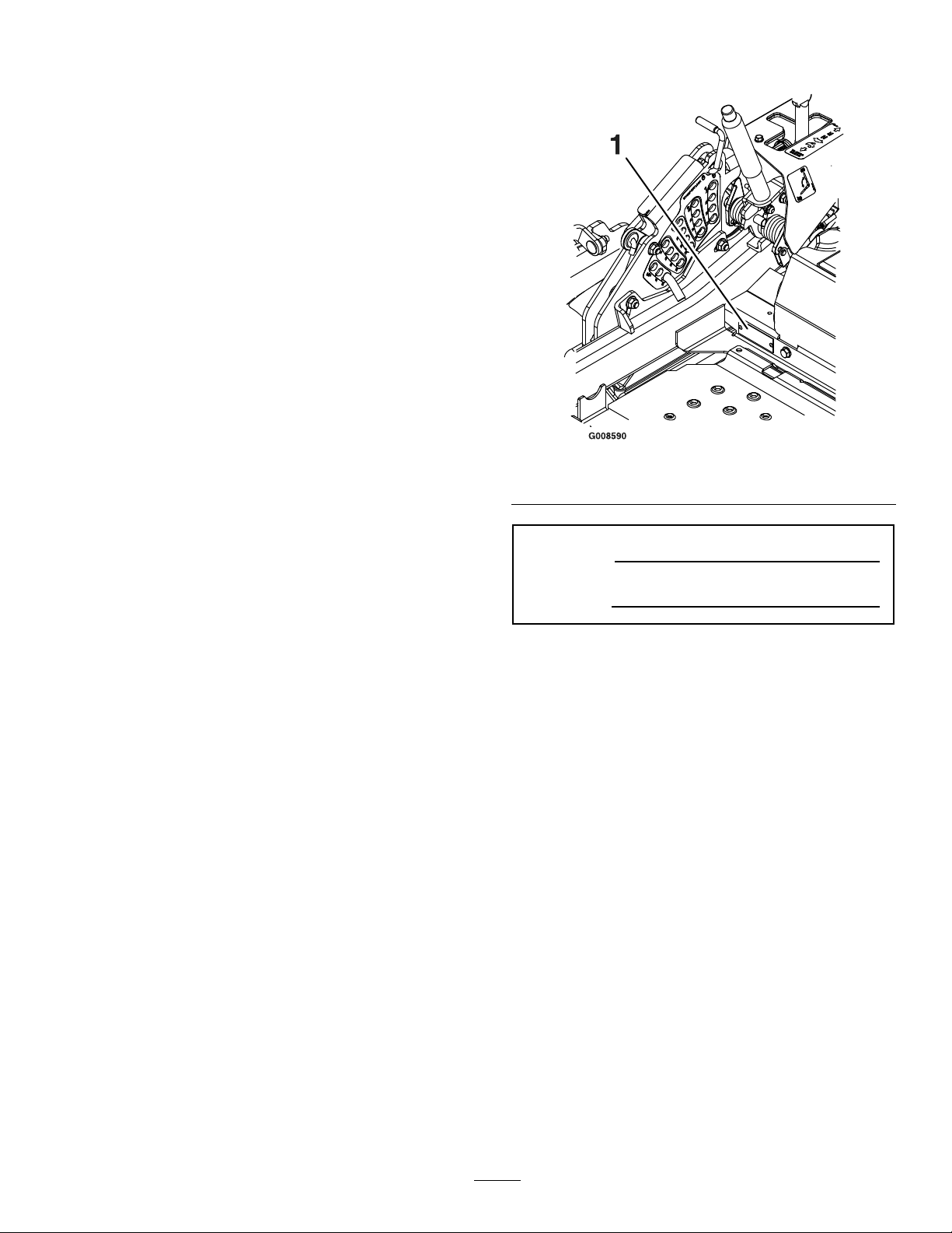
Figure1
1.Modelandserialnumberlocation
ModelNo.
SerialNo.
AllExmarkpartsarethoroughlytestedandinspected
beforeleavingthefactory,however,attentionis
requiredonyourpartifyouaretoobtainthefullest
measureofsatisfactionandperformance.
Wheneveryouneedservice,genuineExmarkparts,
oradditionalinformation,contactanAuthorized
ServiceDealerorExmarkCustomerServiceandhave
themodelandserialnumbersofyourproductready.
Figure1identiesthelocationofthemodelandserial
numbersontheproduct.Writethenumbersinthe
spaceprovided.
3
Page 4

Contents
Introduction...........................................................3
Safety.....................................................................5
SafetyAlertSymbol.........................................5
SafeOperatingPractices..................................5
SafetyandInstructionalDecals.....................10
Specications.......................................................14
ModelNumbers............................................14
Systems.........................................................14
Dimensions...................................................16
TorqueRequirements....................................18
ProductOverview................................................18
Operation.............................................................19
Controls........................................................19
Pre-Start........................................................22
OperatingInstructions..................................22
Transporting.................................................27
Maintenance.........................................................29
RecommendedMaintenanceSchedule(s)...........29
PeriodicMaintenance.......................................30
CheckEngineOilLevel.................................30
CheckMowerBlades.....................................31
CheckSafetyInterlockSystem.......................31
CheckRolloverProtectionsSystems(Roll
Bar)Knobs................................................32
CheckSeatBelt..............................................32
CheckforLooseHardware............................32
ServiceAirCleaner........................................32
ChangeEngineOil........................................33
CheckHydraulicOilLevel.............................33
CheckTirePressures.....................................34
CheckConditionOfBelts..............................34
LubricateGreaseFittings...............................34
LubricateBrakeHandlePivot........................35
LubricateDeckLiftPivot...............................35
CheckSparkPlugs.........................................35
ChangeHydraulicSystemFilterand
Fluid.........................................................35
WheelHub-SlottedNutTorque
Specication..............................................36
CheckEngineCoolantLevel(Kawasaki
Liquid-CooledOnly).................................37
ChangeEngineCoolant(Kawasaki
Liquid-CooledOnly).................................37
CheckSparkArrester(ifequipped).................38
ThreadLockingAdhesives.............................38
Copper-BasedAnti-seize..............................38
DielectricGrease...........................................38
Adjustments.....................................................39
DeckLeveling...............................................39
DeckRemoval...............................................41
PumpDriveBeltTension...............................41
DeckBeltTension........................................41
AdjustingtheParkingBrake...........................41
ElectricClutchAdjustment............................42
MotionControlLinkageAdjustment.............42
MotionControlDamperAdjustment.............43
MotionControlNeutralLockPivot
Adjustment...............................................43
MotionControlHandleAdjustment..............44
MotionControlFullForwardTracking
Adjustment...............................................44
CasterPivotBearingsPre-Load
Adjustment...............................................44
Cleaning...........................................................45
CleanEngineandExhaustSystem
Area..........................................................45
RemoveEngineShroudsandCleanCooling
Fins...........................................................45
CleanHydroFanCoolingGuards..................45
CleanDebrisFromMachine..........................46
CleanGrassBuild-UpUnderDeck................46
WasteDisposal..............................................46
Troubleshooting...................................................47
Schematics...........................................................49
4
Page 5
Safety
Safety
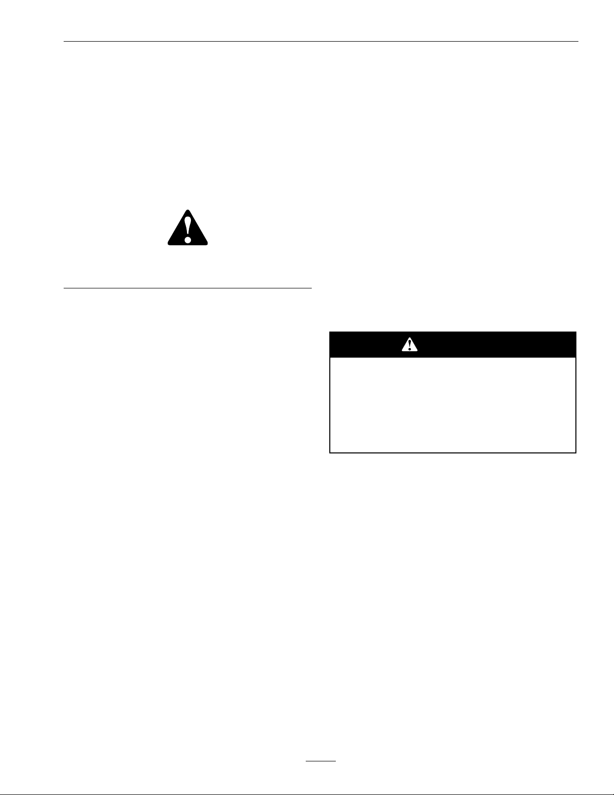
SafetyAlertSymbol
ThisSafetyAlertSymbol(Figure2)isusedbothin
thismanualandonthemachinetoidentifyimportant
safetymessageswhichmustbefollowedtoavoid
accidents
Thissymbolmeans:ATTENTION!BECOME
ALERT!YOURSAFETYISINVOLVED!
Figure2
1.Safetyalertsymbol
Thesafetyalertsymbolappearsaboveinformation
whichalertsyoutounsafeactionsorsituations
andwillbefollowedbythewordDANGER,
WARNING,orCAUTION.
•Neverletchildrenoruntrainedpeopleoperate
orservicetheequipment.Localregulationsmay
restricttheageoftheoperator.
•Theowner/usercanpreventandisresponsible
foraccidentsorinjuriesoccurringtohimselfor
herself,otherpeopleorproperty.
Preparation
•Evaluatetheterraintodeterminewhataccessories
andattachmentsareneededtoproperlyand
safelyperformthejob.Onlyuseaccessoriesand
attachmentsapprovedbyExmark.
•Wearappropriateclothingincludingsafetyglasses,
substantialfootwear,longtrousers,andhearing
protection.DoNotoperatewhenbarefootor
whenwearingopensandals.Longhair,loose
clothingorjewelrymaygettangledinmoving
parts.
CAUTION
DANGER:Whitelettering/Redbackground.
Indicatesanimminentlyhazardoussituationwhich,if
notavoided,Willresultindeathorseriousinjury.
WARNING:Blacklettering/Orangebackground.
Indicatesapotentiallyhazardoussituationwhich,if
notavoided,Couldresultindeathorseriousinjury.
CAUTION:Blacklettering/Yellowbackground.
Indicatesapotentiallyhazardoussituationwhich,if
notavoided,Mayresultinminorormoderateinjury.
Thismanualusestwootherwordstohighlight
information.Importantcallsattentiontospecial
mechanicalinformationandNoteemphasizes
generalinformationworthyofspecialattention.
SafeOperatingPractices
Training
•ReadtheOperator’sManualandothertraining
material.Iftheoperator(s)ormechanic(s)can
notreadEnglishitistheowner’sresponsibilityto
explainthismaterialtothem.
Thismachineproducessoundlevelsin
excessof85dBAattheoperator’searand
cancausehearinglossthroughextended
periodsofexposure.
Wearhearingprotectionwhenoperatingthis
machine.
•Inspecttheareawheretheequipmentistobe
usedandremoveallrocks,toys,sticks,wires,
bones,andotherforeignobjectswhichcanbe
thrownbythemachineandmaycausepersonal
injurytotheoperatororbystanders.
•Becomefamiliarwiththesafeoperationofthe
equipment,operatorcontrols,andsafetysigns.
•Alloperatorsandmechanicsshouldbetrained.
Theownerisresponsiblefortrainingtheusers.
5
Page 6
Safety
DANGER
Incertainconditionsgasolineisextremely
ammableandvaporsareexplosive.
Areorexplosionfromgasolinecanburn
you,others,andcausepropertydamage.
•Fillthefueltankoutdoorsinanopen
area,whentheengineiscold.Wipeup
anygasolinethatspills.
•Neverrellthefueltankordrainthe
machineindoorsorinsideanenclosed
trailer.
•DoNotllthefueltankcompletely
full.Addgasolinetothefueltankuntil
thelevelis1/4to1/2inch(6–13mm)
belowthebottomofthellerneck.This
emptyspaceinthetankallowsgasoline
toexpand.
•Neversmokewhenhandlinggasoline,
andstayawayfromanopenameor
wheregasolinefumesmaybeignitedby
spark.
•Storegasolineinanapprovedcontainer
andkeepitoutofthereachofchildren.
•Addfuelbeforestartingtheengine.
Neverremovethecapofthefueltankor
addfuelwhenengineisrunningorwhen
theengineishot.
•Iffuelisspilled,DoNotattempttostart
theengine.Moveawayfromtheareaof
thespillandavoidcreatinganysourceof
ignitionuntilfuelvaporshavedissipated.
•DoNotoperatewithoutentireexhaust
systeminplaceandinproperworking
condition.
DANGER
Incertainconditionsduringfueling,static
electricitycanbereleasedcausingaspark
whichcanignitegasolinevapors.Areor
explosionfromgasolinecanburnyouand
othersandcausepropertydamage.
•Alwaysplacegasolinecontainersonthe
groundawayfromyourvehiclebefore
lling.
•DoNotllgasolinecontainersinsidea
vehicleoronatruckortrailerbedbecause
interiorcarpetsorplastictruckbedliners
mayinsulatethecontainerandslowthe
lossofanystaticcharge.
•Whenpractical,removegas-powered
equipmentfromthetruckortrailerand
refueltheequipmentwithitswheelson
theground.
•Ifthisisnotpossible,thenrefuelsuch
equipmentonatruckortrailerfroma
portablecontainer,ratherthanfroma
gasolinedispensernozzle.
•Ifagasolinedispensernozzlemustbe
used,keepthenozzleincontactwiththe
rimofthefueltankorcontaineropening
atalltimesuntilfuelingiscomplete.
WARNING
Gasolineisharmfulorfatalifswallowed.
Long-termexposuretovaporshascaused
cancerinlaboratoryanimals.Failuretouse
cautionmaycauseseriousinjuryorillness.
•Avoidprolongedbreathingofvapors.
•Keepfaceawayfromnozzleandgas
tank/containeropening.
•Keepawayfromeyesandskin.
•Neversiphonbymouth.
6
Page 7

Safety
CAUTION
Fueltankventislocatedinsidetheroll
bartube.Removingormodifyingtheroll
barcouldresultinfuelleakageandviolate
emissionsregulations.
•DoNotremoverollbar.
•DoNotweld,drill,ormodifyrollbarin
anyway.
•Checkthattheoperator’spresencecontrols,
safetyswitches,andshieldsareattachedand
functioningproperly.DoNotoperateunlessthey
arefunctioningproperly.
Operation
WARNING
Operatingengineparts,especiallythe
mufer,becomeextremelyhot.Severeburns
canoccuroncontactanddebris,suchas
leaves,grass,brush,etc.cancatchre.
•Allowengineparts,especiallythemufer,
tocoolbeforetouching.
•Neveroperatethemowerwithdamagedguards,
shields,orcovers.Alwayshavesafetyshields,
guards,switchesandotherdevicesinplaceandin
properworkingcondition.
•Nevermowwiththedischargedeectorraised,
removedoralteredunlessthereisagrass
collectionsystemormulchkitinplaceand
workingproperly .
•DoNotchangetheenginegovernorsettingor
overspeedtheengine.
•Stopengine,waitforallmovingpartstostop,
removekeyandengageparkingbrake:
–Beforechecking,cleaningorworkingonthe
mower.
–Afterstrikingaforeignobjectorabnormal
vibrationoccurs(inspectthemowerfor
damageandmakerepairsbeforerestarting
andoperatingthemower).
–Beforeclearingblockages.
–Wheneveryouleavethemower.
•Stopengine,waitforallmovingpartstostop,and
engageparkingbrake:
–Beforerefueling.
–Beforedumpingthegrasscatcher.
•Removeaccumulateddebrisfrommufer
andenginearea.
•Installandmaintaininworkingordera
sparkarresterbeforeusingequipment
onforest-covered,grass-covered,or
brush-coveredunimprovedland.
WARNING
Engineexhaustcontainscarbonmonoxide,
whichisanodorlessdeadlypoisonthatcan
killyou.
DoNotrunengineindoorsorinasmall
connedareawheredangerouscarbon
monoxidefumescancollect.
•Operateonlyindaylightorgoodarticiallight,
keepingawayfromholesandhiddenhazards.
•Besurealldrivesareinneutralandparkingbrake
isengagedbeforestartingengine.Useseatbelts
withtherollbarintheraisedandlockedposition.
WARNING
Hands,feet,hair,clothing,oraccessoriescan
becomeentangledinrotatingparts.Contact
withtherotatingpartscancausetraumatic
amputationorseverelacerations.
•DoNotoperatethemachinewithout
guards,shields,andsafetydevicesin
placeandworkingproperly.
•Keephands,feet,hair,jewelry,orclothing
awayfromrotatingparts.
•NEVERcarrypassengers.DONOToperate
themowerwhenpeople,especiallychildren,or
petsareinthearea.
•Bealert,slowdownandusecautionwhenmaking
turns.Lookbehindandtothesidebefore
changingdirections.
•Stoptheblades,slowdown,andusecautionwhen
crossingsurfacesotherthangrassandwhen
transportingthemowertoandfromtheareato
bemowed.
7
Page 8
Safety
•Beawareofthemowerdischargepathanddirect
dischargeawayfromothers.
•DoNotoperatethemowerundertheinuence
ofalcoholordrugs.
•Useextremecarewhenloadingorunloadingthe
machineintoatrailerortruck.
•Usecarewhenapproachingblindcorners,shrubs,
trees,orotherobjectsthatmayobscurevision.
SlopeOperation
UseExtremecautionwhenmowingand/orturning
onslopesaslossoftractionand/ortip-overcould
occur.Theoperatorisresponsibleforsafeoperation
onslopes.
DANGER
Operatingonwetgrassorsteepslopescan
causeslidingandlossofcontrol.Wheels
droppingoveredges,ditches,steepbanks,or
watercancauserollovers,whichmayresult
inseriousinjury,deathordrowning.
•DoNotmowslopeswhengrassiswet.
•DoNotmowneardrop-offsornearwater.
•DoNotmowslopesgreaterthan15
degrees.
•Reducespeedanduseextremecaution
onslopes.
•Avoidsuddenturnsorrapidspeed
changes.
•Keeptherollbarintheraisedandlocked
positionanduseseatbelt.
•Seeinsidethebackcovertodeterminethe
approximateslopeangleoftheareatobemowed.
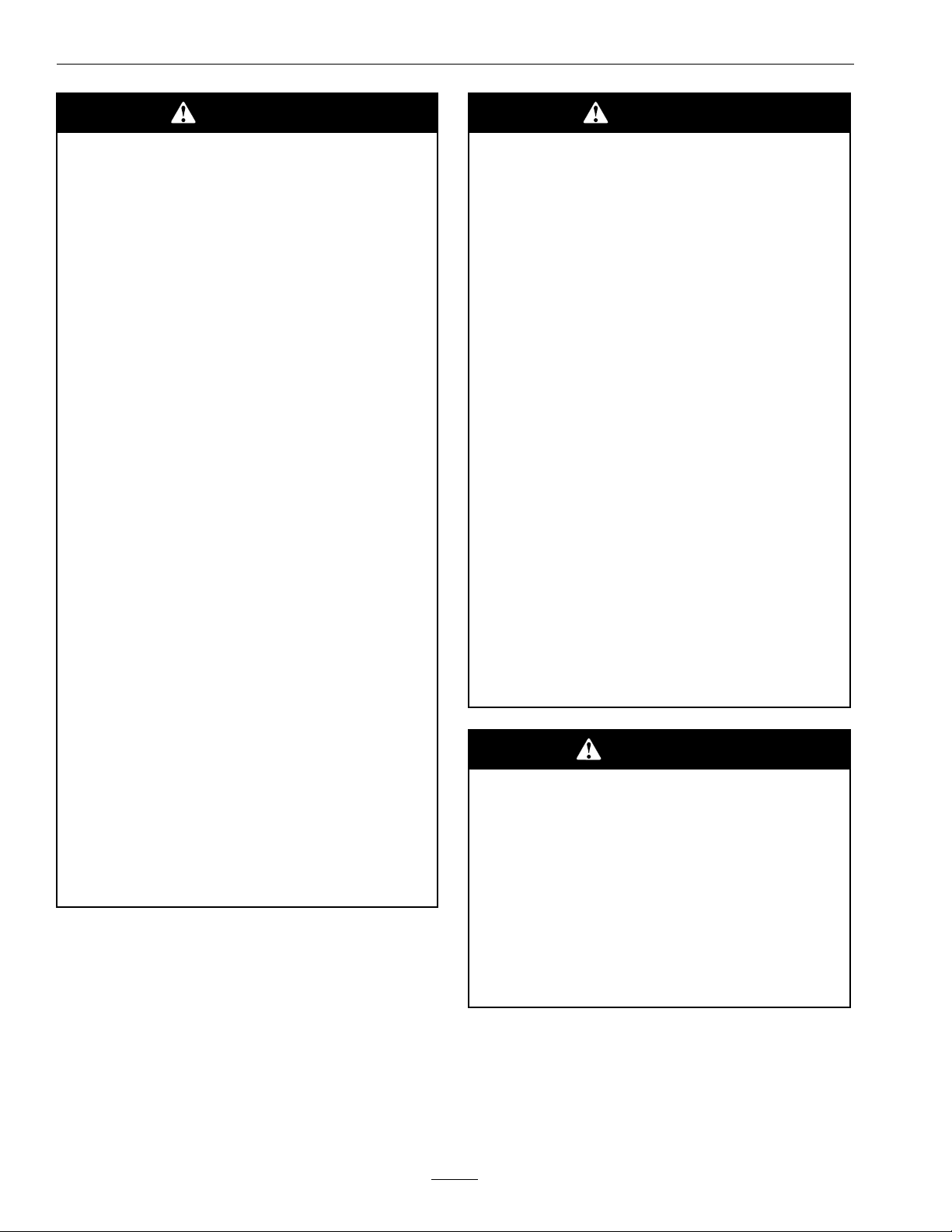
•Useawalkbehindmowerand/orahandtrimmer
neardrop-offs,ditches,steepbanksorwater.
(Figure3).
Figure3
1.SafeZone-Usethemowerhereonslopeslessthan15
degrees
2.DangerZone-Useawalkbehindmowerand/orhand
trimmeronslopesgreaterthan15degrees,near
drop-offsandwater.
3.Water
•Removeormarkobstaclessuchasrocks,tree
limbs,etc.fromthemowingarea.Tallgrasscan
hideobstacles.
•Watchforditches,holes,rocks,dipsandrisesthat
changetheoperatingangle,asroughterraincould
overturnthemachine.
•Avoidsuddenstartswhenmowinguphillbecause
themowermaytipbackwards.
•Beawarethatoperatingonwetgrass,acrosssteep
slopesordownhillmaycausethemowertolose
traction.Lossoftractiontothedrivewheelsmay
resultinslidingandlossofbrakingandsteering.
•Alwaysavoidsuddenstartingorstoppingona
slope.Iftireslosetraction,disengagetheblades
andproceedslowlyofftheslope.
•Followthemanufacturer’srecommendationsfor
wheelweightsorcounterweightstoimprove
stability.
•Useextremecarewithgrasscatchersor
attachments.Thesecanchangethestabilityofthe
machineandcauselossofcontrol.
UsingtheRolloverProtectionSystem
(ROPS)
ARolloverProtectionSystem(rollbar)isinstalled
ontheunit.
8
Page 9

Safety
WARNING
Thereisnorolloverprotectionwhentheroll
barisdown.Wheelsdroppingoveredges,
ditches,steepbanks,orwatercancause
rollovers,whichmayresultinseriousinjury,
deathordrowning.
•Keeptherollbarintheraisedandlocked
positionanduseseatbelt.
•Lowertherollbaronlywhenabsolutely
necessary.
•DoNotwearseatbeltwhentherollbar
isdown.
•Driveslowlyandcarefully.
•Raisetherollbarassoonasclearance
permits.
•Checkcarefullyforoverheadclearances(i.e.
branches,doorways,andelectricalwires)before
drivingunderanyobjectsandDoNotcontact
them.
•Intheeventofarollover,taketheunittoan
AuthorizedServiceDealertohavetheROPS
inspected.
•Disconnectbatteryorremovesparkplugwire
beforemakinganyrepairs.Disconnectthe
negativeterminalrstandthepositivelast.
Reconnectpositiverstandnegativelast.
•Usecarewhencheckingblades.Wraptheblade(s)
orweargloves,andusecautionwhenservicing
them.Onlyreplacedamagedblades.Never
straightenorweldthem.
•Keephandsandfeetawayfrommovingparts.
Ifpossible,DoNotmakeadjustmentswiththe
enginerunning.
•Chargebatteriesinanopenwellventilatedarea,
awayfromsparkandames.Unplugcharger
beforeconnectingordisconnectingfrombattery.
Wearprotectiveclothinganduseinsulatedtools.
•Keepallguards,shieldsandallsafetydevicesin
placeandinsafeworkingcondition.
•Checkallboltsfrequentlytomaintainproper
tightness.
•Frequentlycheckforwornordeteriorating
componentsthatcouldcreateahazard.
•Allreplacementpartsmustbethesameas
orequivalenttothepartssuppliedasoriginal
equipment.
MaintenanceandStorage
•Disengagedrives,lowerimplement,setparking
brake,stopengineandremovekeyordisconnect
sparkplugwire.Waitforallmovementtostop
beforeadjusting,cleaningorrepairing.
•Keepengineandengineareafreefrom
accumulationofgrass,leaves,excessivegrease
oroil,andotherdebriswhichcanaccumulate
intheseareas.Thesematerialscanbecome
combustibleandmayresultinare.
•LetenginecoolbeforestoringandDoNotstore
nearameoranyenclosedareawhereopenpilot
lightsorheatappliancesarepresent.
•Shutofffuelwhilestoringortransporting.Do
Notstorefuelnearamesordrainindoors.
•Parkmachineonlevelground.Neverallow
untrainedpersonneltoservicemachine.
•Usejackstandstosupportcomponentswhen
required.
•Carefullyreleasepressurefromcomponentswith
storedenergy.
WARNING
Hydraulicuidescapingunderpressure
canpenetrateskinandcauseinjury.Fluid
accidentallyinjectedintotheskinmustbe
surgicallyremovedwithinafewhoursbya
doctorfamiliarwiththisformofinjuryor
gangrenemayresult.
•Keepbodyandhandsawayfrompinhole
leaksornozzlesthatejecthighpressure
hydraulicuid.
•Usecardboardorpaper,notyourhands,
tondhydraulicleaks.
•Safelyrelieveallpressureinthehydraulic
systembyplacingthemotioncontrol
leversinneutralandshuttingoffthe
enginebeforeperforminganyworkon
thehydraulicsystem.
9
Page 10
Safety
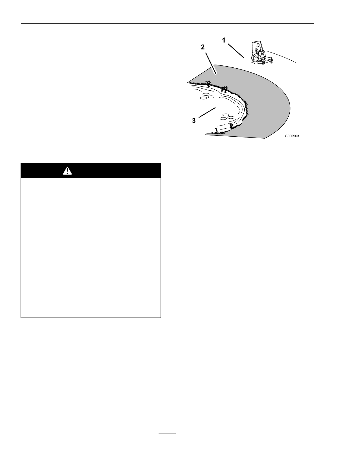
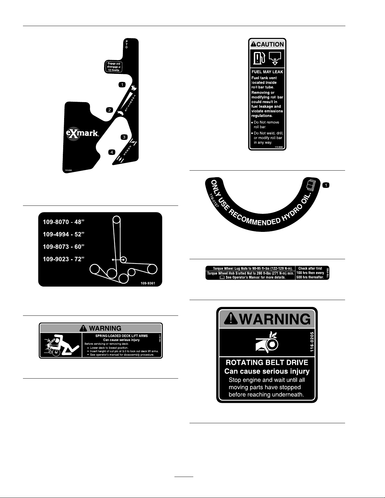
SafetyandInstructionalDecals
•Keepallsafetysignslegible.Removeallgrease,
dirtanddebrisfromsafetysignsandinstructional
labels.
•Replaceallworn,damaged,ormissingsafety
signs.
•Whenreplacementcomponentsareinstalled,be
surethatcurrentsafetysignsareafxedtothe
replacedcomponents.
•Ifanattachmentoraccessoryhasbeeninstalled,
makesurecurrentsafetysignsarevisible.
1-303508
•Newsafetysignsmaybeobtainedfrom
yourauthorizedExmarkequipmentdealeror
distributororfromExmarkMfg.Co.Inc.
•Safetysignsmaybeafxedbypeelingoffthe
backingtoexposetheadhesivesurface.Apply
onlytoaclean,drysurface.Smoothtoremove
anyairbubbles.
•Familiarizeyourselfwiththefollowingsafetysigns
andinstructionlabels.Theyarecriticaltothesafe
operationofyourExmarkcommercialmower.
1-633922
1-403005
98-5954
103-2076
10
Page 11
Safety
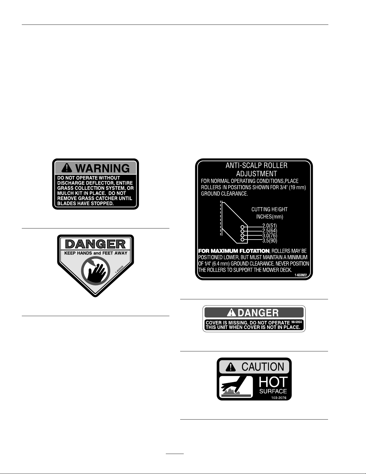
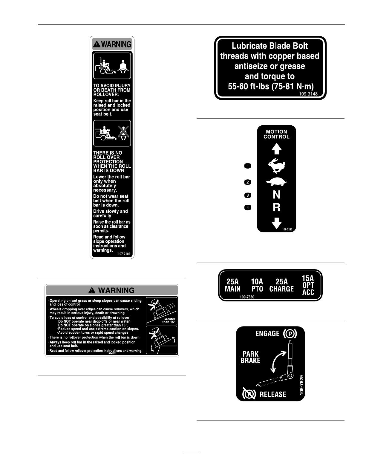
109-3148
107-2102
107-2112
109-7232
1.Fast3.Neutral
2.Slow
109-7330
109-7929
4.Reverse
11
Page 12
Safety
1.Throttle–fast3.Choke–on
2.Throttle–slow
116-0090
109-8483
4.Choke–off
DeckDriveBeltRouting
116-0157
1.SeeOperator’smanual
116-0165
109-9361
109-9477
116-0205
12
Page 13
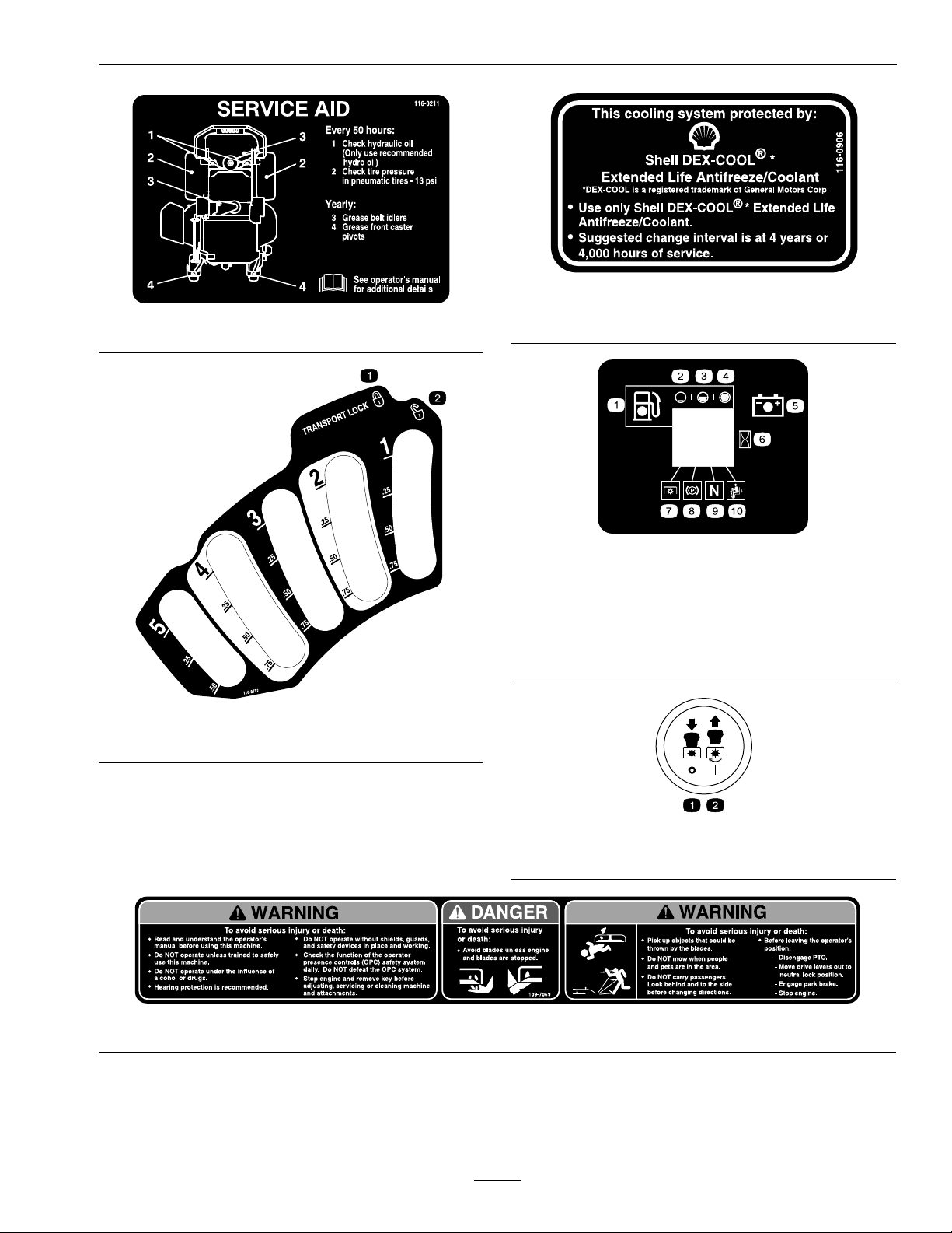
116-0211
Safety
116-0906
ForKawasakiLiquid-CooledOnly
116-0752
1.Latch2.Unlatch
MessageDisplay
1.Fuel6.Hourmeter
2.Empty
3.Half
4.Full9.Neutral
5.Battery
7.PTO
8.Parkingbrake
10.Operatorpresence
PTOSwitchSymbols
1.PTO–disengage2.PTO–engage
switch
109-7069
13
Page 14

Specications
Specications
ModelNumbers
SerialNos:790,000andHigher
LZAS20BV484;LZAS20KC484;LZAS23KC524;LZAS25KC604;LZAS26LKA604;LZAS27KC524;
LZAS27KC604;LZAS29KA724
Systems
Engine
•EngineSpecications:SeeyourEngineOwner’s
Manual
•RPM:
–AllunitsexceptLZAS20BV484and
LZAS20KC484:FullSpeed:3750±50RPM
(PTOnotengaged)Idle:1500±100RPM
–LZAS20BV484andLZAS20KC484:Full
Speed:3750+0/-50RPM(PTOnotengaged)
Idle:1500±100RPM
FuelSystem
•Capacity:12.0gal.(45.4L)
•TypeofFuel:Regularunleadedgasoline,87
octaneorhigher.
•FuelFilter:
–Briggs&Stratton:
Briggs&StrattonP/N691035
–Kohler:
KohlerP/N2405013
–Kawasaki:
KawasakiP/N49019-7001
•FuelShut-OffValve:
AllUnits:1/4turnincrements(“ON”,“OFF”).
•Fuelleveleightsegmentdisplay—righthand
controlpanel.
•Lowfuelindicatorlight.
ElectricalSystem
•ChargingSystem:FlywheelAlternator
•ChargingCapacity:
–Briggs&Stratton:16amps
–KohlerandKawasakiAir-Cooled:15amps
–KawasakiLiquid-Cooled:20amps
•BatteryType:BCIGroupU1
•RecommendedMinimumBatteryCCA:260CCA
•BatteryVoltage:12Volt
•LowVoltageLight—RHcontrolpanel
•Polarity:NegativeGround
•Fuses:
Allunits:
–25ampmainfuse
–25ampchargingsystemfuse
–10ampPTOfuse
–15ampaccessoryfuse
SafetyInterlockSystem
•LCDindicatorsappearforthePTO,parkbrake,
drivelevers,andoperatorpresenceinthemessage
displayontheRHcontrolpanel.
•PTOmustbedisengaged,brakeengaged,and
motioncontrolleversout(neutrallock)tostart
engine.(Itisnotnecessaryfortheoperatortobe
intheseattostarttheengine.)
•OperatormustbeinseatwhenPTOisengaged,
brakeisdisengaged,ormotioncontrolleversare
movedinorenginewillstop.
•Enginewillstopifeithertheleft,theright,or
bothleversaremovedfromneutrallockposition
whilebrakeisengaged.
CoolingSystem(Kawasaki
Liquid-CooledOnly)
•Fan:Continuousoperationwithenginerunning.
•CoolantLiquid:50/50mixofDexCool©
extendedlifeantifreezeandwater.
•CoolantCapacity:3.1quarts
14
Page 15

Specications
OperatorControls
•SteeringandMotionControl:
Note:Motioncontrolleversareadjustableto
twoheights.
–Separatelevers,oneachsideoftheconsole,
controlspeedanddirectionoftravelofthe
respectivedrivewheels.
–Steeringiscontrolledbyvaryingtheposition
oftheleversrelativetoeachother.
–Movingmotioncontrolleversoutward(in
slots)locksthedrivesysteminneutral.
•PTOEngagementSwitch:Engageselectricclutch
(todrivebelt)whichengagesmowerblades.
•ParkingBrakeLever:Engagesparkingbrake.
•ParkingBrakeReleaseButton:Releasesparking
brake.
•DeckHeightAdjustmentLever:Setscutting
heighttodesiredposition.
•DeckLiftPedal:Footpedalthatliftsdeck.
•TransportLock:
–Latchingposition:Automaticallylatchesat
thetransportposition.
–Unlatchingposition:Deckdoesnotlatchat
thetransportposition.
•Armrests:
–Standardseat:foampaddedadjustableip-up
armrests.
–Suspensionseat:moldedadjustableip-up
armrests.
•SeatSafetySwitch:
Integratedseatswitch.Timedelayseatswitch
eliminatesroughgroundcut-outs.
HydrostaticGroundDriveSystem
•Twounitizedhydrostatictransmissions:
12ccParkeraxialpistonpump
240ccParkergerolermotor
•HydraulicOilType:ExmarkPremiumHydrooil.
•HydraulicOilCapacity:52oz(1.5L)perside
•HydraulicFilter:P/N116-0164
•Speeds:
–0-10mph(16.1km/hr)forward.
–0-5.5mph(8.9km/hr)reverse.
•Drivewheelreleasevalvesallowmachinetobe
movedwhenengineisnotrunning.
Tires&Wheels
Seat
•Type:Standardseatwithhighback,extra
widefoampaddedseatcushionwithinternal
suspension,thickbolstering,armrests,integral
safetyswitch.
Optionalseataccessoriesforunitswithstandard
seats:
–Customridesuspensionsystemtoenhance
StandardSeat.Addsapproximately3inches
(7.6cm)toseatheight.
–Deluxesuspensionseatwithhighback,low
prolefoam-in-placecushion(dampened,
adjustablespringsuspension),armrests,and
integralsafetyswitch.Seatheightremainsthe
same.
–SeatIsolationSystemforreducedvibration,
toenhancerideofstandardseat,standardseat
withCustomRideSeatSuspensionorDeluxe
SuspensionSeat.Addsapproximately1inch
(2.5cm)toseatheight.
•Mounting:Adjustableforeandaftonseattracks.
Quantity
Tread
Size(72Deck)
Size(60Deck)
Size(48&52
Decks)
PlyRating
Pressure
CuttingDeck
•CuttingWidth:
–48inchDeck:(121.9cm)
–52inchDeck:(132.1cm)
–60inchDeck:(152.4cm)
–72inchDeck:(182.9cm)
•Discharge:Side
DriveFrontCaster
Pneumatic
(Air-Filled)
22
TurfMasterSmooth
24x12.00-1213x6.50-6
24x12.00-1213x5.00-6
24x9.50-1213x5.00-6
4
13psi(90kPa)
Semi-Pneumatic
15
Page 16

Specications
•BladeSize:(3ea.)
–48inchDeck:16.25inches(41.3cm)
–52inchDeck:18.00inches(45.7cm)
–60inchDeck:20.50inches(52.1cm)
–72inchDeck:24.50inches(62.2cm)
•BladeSpindles:Solidsteelspindleswith1.00inch
(25mm)I.D.bearings.
•DeckDrive:
Electricclutch:
–48and52inchDecks:“B”Sectionbeltwith
self-tensioningidler.
–60and72inchDecks:5VSectionbeltwith
self-tensioningidler.
•Deck:
Fulloatingdeckisattachedtoout-frontsupport
frame.Anti-scalprollersprovidemaximumturf
protection.Deckdesignallowsforbagging,
mulchingorsidedischarge.
Dimensions
OverallWidth:
48inchDeck52inchDeck
WithoutDeck45.7inches
(116.1cm)
DeectorUp51.8inches
(131.6cm)
DeectorDown59.6inches
(151.4cm)
60inchDeck72inchDeck
WithoutDeck53.0inches
(134.6cm)
DeectorUp62.5inches
(158.8cm)
DeectorDown72.8inches
(184.9cm)
OverallLength:
45.7inches
(116.1cm)
56.3inches
(143.0cm)
64.8inches
(164.6cm)
59.1inches
(150.1cm)
73.5inches
(186.7cm)
84.9inches
(215.6cm)
–48inchDeck:3anti-scalprollers
–52inchDeck:3anti-scalprollers
–60inchDeck:4anti-scalprollers
–72inchDeck:4anti-scalprollers
•DeckDepth:
–48inchDeck:5.5inches(14cm)
–52inchDeck:5.5inches(14cm)
–60inchDeck:5.5inches(14cm)
–72inchDeck:5.5inches(14cm)
•CuttingHeightAdjustment:
Footactivatedleverisusedtoadjustthecutting
heightfrom1inch(2.5cm)to51/2inches(14
cm)in1/4inch(6.4mm)increments.
•MulchingKit:Optional.
48inchDeck52inchDeck
RollBar-Up79.2inches
(201.2cm)
RollBar-Down80.9inches
(205.5cm)
60inchDeck72inchDeck
RollBar-Up83.1inches
(211.1cm)
RollBar-Down84.8inches
(215.4cm)
79.2inches
(201.2cm)
80.9inches
(205.5cm)
86.1inches
(218.7cm)
87.8inches
(223.0cm)
OverallHeight:
RollBar-UpRollBar-Down
70.5inches(179.1cm)46.8inches(118.9cm)
16
Page 17

Specications
TreadWidth:(CentertoCenterof
Tires,Widthwise)
48inchDeck52inchDeck
DriveWheels36.2inches
(91.9cm)
CasterWheels32.8inches
(83.3cm)
60inchDeck72inchDeck
DriveWheels41.6inches
(105.7cm)
CasterWheels39.5inches
(100.3cm)
36.2inches
(91.9cm)
32.8inches
(83.3cm)
43.6inches
(110.7cm)
47.1inches
(119.6cm)
WheelBase:(CenterofCasterTireto
CenterofDriveTire)
48inch
Deck
48.0inches
(121.9cm)
52inch
Deck
48.0inches
(121.9cm)
60inch
Deck
50.6inches
(128.5cm)
72inch
Deck
53.6inches
(136.1cm)
CurbWeight:
20HP
Briggs&
Stratton
Units
20HP
Kohler
Units
23HP
Kohler
Units
25HP
Kohler
Units
26HP
Kawasaki
Units
27HP
Kohler
Units
29HP
Kawasaki
Units
48inch
Deck
1081lb
(490kg)
1115lb
(506kg)
—
——
——
—
———
52inch
Deck
1108lb
(503kg)
1108lb
(503kg)
60inch
Deck
——
1165lb
(528kg)
1177lb
(534kg)
1165lb
(528kg)
72inch
Deck
—
—
—
1234lb
(560kg)
AccessoryWeightTableWorksheet:
Usethetablebelowtodetermineifextraweight
isrequiredfortheunit.Identifytheaccessories
andcorrectdecksizeandplacethecorresponding
valuesintheAccessoryScorecolumn.IftheTotal
AccessoryScoremeetsthefollowing,addthe
recommendedweightkit.
Note:The72inchdeckdoesnotrequireaweightkit.
48inch
Deck
LightKit
Michigan
Seat/CRSS
Bagger
Pneumatic
Caster
Tires
MulchKit
StriperKit-300
OCD02-6-6-4
HitchKit
Sunshade
Kit
TotalAccessoryScoreRequiredWeightKit(s)
0–9
10–19
20andHigher*Two116-1173Undertoe
11
-3-3-5
*48and52inchunitsthatcomewithanundertoe
boardweightasstandard,canaddanadditionaltoe
boardweightforprimaryaccessoryweighting(scores
10-19);andfronttoeboardweightkitforsecondary
accessoryweighting(scores20andhigher).Other
unitsshouldinstallarstundertoeboardkitfor
primaryaccessoryweighting(scores10-19);anda
secondundertoeboardkitforsecondaryaccessory
weighting(scores20andhigher).
52inch
Deck
222
103
003
7
111
2
TotalAccessoryScore
65
3
60inch
Deck
Nonerequired
*116-1173Undertoe
boardmountweightkit
boardmountweightkits
orone116-1173Undertoe
boardmountweightkit
andone116-1238Front
toeboardmountweightkit
Accessory
Score
2
17
Page 18
ProductOverview
*60inchunitswhichalreadyhaveanundertoeboard
mountweightasstandardrequires116-1238fronttoe
boardtopmountkitinsteadof116-1173.
TorqueRequirements
BoltLocation
BladeDriveSheave
MountingNut
BladeMountingBolt
(lubricatewithanti-seize)
Anti-ScalpRollerNyloc
NutSeeFigure19
Anti-ScalpRollerHex
CapscrewSeeFigure19
EngineMountingBolts
(Briggs&Stratton20HP)
(Kohler20-27HP)
(Kawasaki26HP
Liquid-Cooled)
(Kawasaki29HP)
WheelLugNuts
WheelMotorMounting
Bolts
Torque
140-145ft-lb(190-197
N-m)
55-60ft-lb(75-81N-m)
30-35ft-lb(41-47N-m)
50-55ft-lb(68-75N-m)
27-33ft-lb(37-45N-m)
27-33ft-lb(37-45N-m)
17-21ft-lb(23-28N-m)
27-33ft-lb(37-45N-m)
90-95ft-lb(122-129N-m)
72-77ft-lb(98-104N-m)
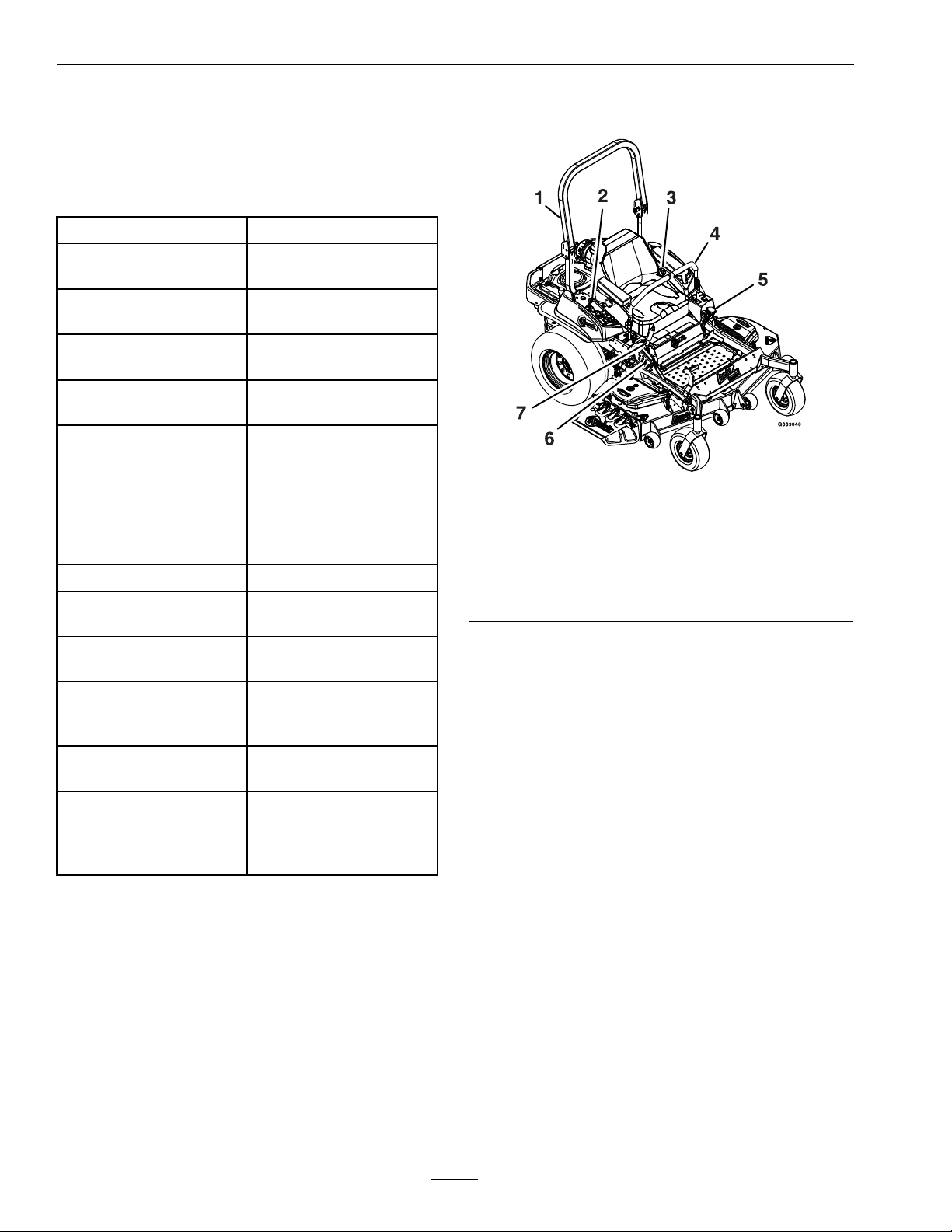
ProductOverview
1.RolloverProtection
System(ROPS)
2.EngineControls(right
console)
3.Seatbelt
4.Motioncontrollevers
Figure4
5.Fuelcap
6.Heightofcutadjustment
7.Parkingbrake
WheelHubSlottedNutminimum200ft-lb
(271N-m)
RolloverProtection
System(RollBar)1/2
inchMountingBolts
ClutchRetainingBolt
(securedwiththreadlocker)
HydroParkBrakeCable
Anchor1/2inchMounting
Bolt(securedwith
threadlocker)
75-80ft-lb(102-108N-m)
55-60ft-lb(75-81N-m)
67-89ft-lb(91-121N-m)
18
Page 19

Operation
Operation
Note:Determinetheleftandrightsidesofthe
machinefromthenormaloperatingposition.
Controls
MotionControlLevers
Themotioncontrolleverslocatedoneachsideof
theconsolecontroltheforwardandreversemotion
ofthemachine.
Movingtheleversforwardorbackwardturns
thewheelonthesamesideforwardorreverse
respectively.Wheelspeedisproportionaltothe
amounttheleverismoved.
Movingtheleversoutwardfromthecenterposition
intotheT-slotlocksthemintheneutralposition
(Figure5).
Whenthemotioncontrolleversareintheneutral
position,theLCDindicatorappearsinthemessage
displayontheRHconsole(seeFigure9).
ChokeControl
Locatedonrightconsole(blacklever)(seeFigure6).
Thechokeisusedtoaidinstartingacoldengine.
Movingthechokeleverforwardwillputthechokein
the“ON”positionandmovingthechokelevertothe
rear,tothedetent,willputthechokeinthe“OFF”
position.DoNotrunawarmenginewithchokein
the“ON”position.
Figure6
RightConsole
1.Neutrallockposition
(handlesout)
2.Neutraloperateposition
(handlesin)
3.FrontofUnit
Figure5
4.Forward
5.Neutral(operate)
6.Reverse
1.WarningBuzzer(KawasakiLiquid-CooledOnly)
2.Fuses
3.Moduledisplay
4.Ignitionswitch
5.PTOengagementswitch
6.Throttle
7.Choke
8.Coolanttemperaturegauge(KawasakiLiquid-Cooled
Only)
ThrottleControl
Locatedonrightconsole(redlever)(seeFigure6).
Thethrottleisusedtocontrolenginespeed.Moving
thethrottleleverforwardwillincreaseenginespeed
andmovingthethrottlelevertotherearwilldecrease
enginespeed.Movingthethrottleforwardintothe
detentisfullthrottle.
BrakeLever
Locatedonrightsideofunit,justtothefrontofthe
RHmotioncontrollever.
Thebrakeleverengagesaparkingbrakeonthedrive
wheels.
19
Page 20

Operation
Note:TheLCDindicatorappearsinthemessage
displayontheRHconsolewhentheparkbrakeis
engaged(seeFigure9).
Pulltheleverupandrearwardtoengagethebrake.
Depressthereleasebuttonandpushdownwardto
disengagethebrake.
Figure7
1.Releasebutton2.Parkbrake
Theunitmustbetieddownandbrakeengagedwhen
transporting.
IgnitionSwitch
Locatedonrightconsole(seeFigure6).
Theignitionswitchisusedtostartandstopthe
engine.Theswitchhasthreepositions“OFF”,“ON”
and“START”.Insertkeyintoswitchandrotate
clockwisetothe“ON”position.Rotateclockwiseto
thenextpositiontoengagethestarter(keymustbe
heldagainstspringpressureinthisposition).Allow
thekeytoreturntothe“on”positionimmediately
aftertheenginestarts.
disengagedtostartengine.(Itisnotnecessaryforthe
operatortobeintheseattostarttheengine.)
HourMeter
Locatedontherightconsoleinthemessagedisplay
(seeFigure6andFigure9).
Thehourmeterrecordsthenumberofhoursthat
theenginehasrun.
Figure9
1.LCDIndicators
2.Lowfuelindicatorlight
3.Fuellevelbardisplay
4.Lowvoltageindicatorlight
5.Hour/Voltagedisplay
Hoursarerecordedwhenthekeyisonandtheengine
isrunning(batteryvoltageis12.8Vorhigher)or
whenthekeyisonandtheoperatorisintheseat.
Thehourmeterisrecordingwhenthedecimalpoint
isashinginHour/Voltagedisplay .
Figure8
1.Off3.Start
2.On
Note:Brakemustbeengaged,motioncontrol
leversout(neutrallockposition)andPTOswitch
Hoursaredisplayedwhenthekeyisoffandwhen
themachineisrunning.
Note:Iftheignitionkeyisturnedtothe“ON”
positionforafewsecondsbeforecrankingthe
engine,thebatteryvoltagewilldisplayinthearea
wherethehoursarenormallydisplayed.
Note:TheLCDindicatorsappearwheneach
controlmeetsthe“safetostart”mode(e.g.the
indicatorturnsonwhentheoperatorisintheseat.)
20
Page 21

FuelShut-OffValve
Locatedbehindandbelowtheseat.
Thefuelshut-offvalveisusedtoshutoffthefuel
whenthemachinewillnotbeusedforafewdays,
duringtransporttoandfromthejobsite,andwhen
parkedinsideabuilding.
Alignvalvehandlewiththefuellinetoopen.Rotate
90°toclose.
Operation
FuelGauge
Locatedontherightconsoleinthemessagedisplay
(seeFigure6andFigure9).
Thefuellevelisshownonabardisplay.Theindicator
lightappearswhenthefuellevelislow(approximately
onegallonremaininginthetank).
DriveWheelReleaseValves
WARNING
Handsmaybecomeentangledintherotating
drivecomponentsbelowtheenginedeck,
whichcouldresultinseriousinjuryordeath.
Stopengine,removekey,allowallthemoving
partstostopbeforeaccessingthedrivewheel
releasevalves.
WARNING
Theengineandhydraulicdriveunitscan
becomeveryhot.T ouchingahotengineor
hydraulicdriveunitscancausesevereburns.
Figure10
1.Handlein“released”position
2.Handlein“operating”position
Toreleasethedrivesystem(seeitem1inFigure10),
rotatethehandle1/4turntotheverticalposition
untilithitsagainstthestop.
Toresetthedrivesystem(seeitem2inFigure10),
rotatethehandle1/4turntothehorizontalposition
untilithitsagainstthestop.
Note:Thehandlemustbehorizontalandagainst
thestopforoperation.
DoNottowmachine.
PTOEngagementSwitch
Locatedonrightconsole(seeFigure6).
Switchmustbepulledout(up)toengagetheblades.
Switchispushedintodisengagetheblades.
TheLCDindicatorwillappearwhenthePTOswitch
isdisengaged(seeFigure9).
LowVoltageIndicator
Allowtheengineandhydraulicdriveunitsto
coolcompletelybeforeaccessingthedrive
wheelreleasevalves.
Locatedonthebackoftheunitizedhydraulicdrive
units,belowtheenginedeck.
Duringnormaloperatingconditions,thedrivewheel
releasevalvesarepositionedhorizontally.Ifthe
machinehastobepushedbyhand,thevalvesmust
beinthe“released”position(seeFigure10).
Locatedontherightconsoleinthemessagedisplay
(seeFigure6andFigure9).
Alowvoltagecondition(lessthan12.3volts)exists
whentheLCDindicatorappearsonthemessage
displaywhiletheengineisrunning.
Iftheignitionkeyisturnedtothe“ON”positionfor
afewsecondsbeforecrankingtheengine,thebattery
voltagewilldisplayintheareawherethehoursare
normallydisplayed.
Note:Theindicatornormallyappearswhenthe
engineisoffandthekeyswitchisturnedtothe
“ON”position.
21
Page 22

Operation
CoolantTemperatureGauge
(KawasakiLiquid-CooledOnly)
Locatedontherightconsole(seeFigure6).
Thecoolanttemperaturegaugemonitorsthe
temperatureoftheenginecoolant.Duringnormal
operatingconditionsthegaugeshouldbeinthegreen
range.Anengineoverheatingconditioniswhenthe
bardisplaygoestotheyelloworredrangeandan
alarmsounds.RefertotheWarningBuzzersection.
Figure11
1.Green
2.Yellow4.Bardisplay
3.Red
Inthenon-latchingposition,thedeckwill
automaticallyreturntothecuttingheightwhenthe
pedalislowered(seeitem3inFigure12).
Figure12
1.Latchingposition3.Non-latchingposition
2.Transportlockcontrol
Pre-Start
Fillfueltank.Forbestresultsuseonlyclean,fresh
regulargradeunleadedgasolinewithanoctanerating
of87orhigher.
WarningBuzzer(Kawasaki
Liquid-CooledOnly)
Locatedonthesideoftherighthandconsole(see
Figure6).
Thebuzzerisawarningsignalthattheengineis
overheating.SeetheTroubleshootingsection.
DeckLiftPedal
Locatedattherightfrontcorneroftheoorpan.
Pushthepedalforwardwithyourfoottoraisethe
cuttingdeck.Allowthepedaltomoverearwardto
lowerthecuttingdecktothecutheightthathasbeen
set.
TransportLock
Locatedontheheightofcutadjustmentplatestothe
rightoftheparkingbrake.
Positioninthetransportlatchingpositionto
automaticallylatchthecuttingdeckwhenraisedto
thetransportposition(seeitem1inFigure12).
DoNotaddoiltogasoline.
DoNotoverllfueltank.Neverllthefueltankso
thatthefuellevelrisesabovealevelthatis1/2inch
(13mm)belowthebottomofthellernecktoallow
forfuelexpansionandpreventfuelspillage.
Makesureyouunderstandthecontrols,their
locations,theirfunctions,andtheirsafety
requirements.
RefertotheMaintenancesectionandperformallthe
necessaryinspectionandmaintenancesteps.
OperatingInstructions
RaisetheRolloverProtectionSystem
(ROPS)
Important:Therollbarisanintegraland
effectivesafetydevice.Keeptherollbarinthe
raisedandlockedpositionwhenoperatingthe
mower.Lowertherollbartemporarilyonlywhen
absolutelynecessary.
1.Theknobmustbecompletelylatchedwiththe
tabsinterlockingasshowninFigure13tolock
therollbarintheraised,operateposition.
22
Page 23

2.Applyforwardpressuretotheupperhoopofthe
rollbar.
3.Pulltheknobandrotate90°toholdinthe
unlatchedpositiontolowertherollbar.
4.Toreturntotheoperateposition,raisetheroll
bar,andthenrotateknobs90°sothatthetabs
interlockpartially.Applyforwardpressuretothe
rollbarupperhoopandobservethattheknobs
returntothecompletelylatchedposition.
Operation
Figure14
1.Engaged2.Partiallyengaged—Do
NotoperatewithROPS
inthiscondition.
Important:Alwaysusetheseatbeltwiththe
rollbarintheoperate(raised)position.Ensure
thattherearpartoftheseatissecuredwiththe
seatlatch.
Figure13
1.Rollbarupperhoop
2.Knobin“latched”position
3.Pullknobtounlatch
4.Rotate90°toholdunlatched
5.Knobin“unlatched”position
5.Makesuretheknobsarefullyengagedwiththe
rollbarintheraisedposition.Theupperhoopof
therollbarmayneedtobepushedforwardor
pulledrearwardtogetbothknobsfullyengaged
(seeFigure14).
OpentheFuelShut-OffValve
Thefuelshutoffvalveislocatedbehindandbelow
theseat.Rotatethevalveandalignwiththefuelline
toopen.
StartingtheEngine
1.Movethemotioncontrolleversouttotheneutral
lockposition.
2.Pullupandbackontheparkingbrakeleverto
engagetheparkingbrake.
3.PushdownonthePTOswitchtothe“disengage”
position.
Note:Itisnotnecessaryfortheoperatortobe
intheseattostarttheengine.
4.Placethethrottlemidwaybetweenthe“SLOW”
and“FAST”positions.
5.Onacoldengine,pushthechokeleverforward
intothe“ON”position.
Onawarmengine,leavethechokeinthe“OFF”
position.
6.Turnignitionswitchtothe“START”position.
Releasetheswitchassoonastheenginestarts.
Important:DoNotcranktheengine
continuouslyformorethantensecondsata
time.Iftheenginedoesnotstart,allowa60
secondcool-downperiodbetweenstarting
23
Page 24

Operation
attempts.Failuretofollowtheseguidelines
canburnoutthestartermotor.
7.Ifthechokeisinthe“ON”position,gradually
returnchoketothe“OFF”positionastheengine
warmsup.
EngagingthePTO
DANGER
Therotatingbladesunderthemowerdeck
aredangerous.Bladecontactcancause
seriousinjuryorkillyou.
DoNotputhandsorfeetunderthemower
ormowerdeckwhenthebladesareengaged.
DANGER
Anuncovereddischargeopeningwillallow
objectstobethrowninanoperator’sor
bystander’sdirection.Also,contactwiththe
bladecouldoccur.Thrownobjectsorblade
contactcancauseseriousinjuryordeath.
StoppingtheEngine
1.Bringtheunittoafullstop.
2.DisengagethePTO.
3.Movethemotioncontrolleversouttotheneutral
lockposition.
4.Engagetheparkingbrake.
5.Placethethrottlemidwaybetweenthe“SLOW”
and“FAST”positions.
6.Allowtheenginetorunforaminimumof15
seconds,thenturntheignitionswitchtothe
“OFF”positiontostoptheengine.
7.Removethekeytopreventchildrenorother
unauthorizedpersonsfromstartingengine.
8.Closethefuelshut-offvalve,locatedbehindand
belowtheseat,whenthemachinewillnotbein
useforafewdays,whentransporting,orwhen
theunitisparkedinsideabuilding.
DrivingtheMachine
CAUTION
Neveroperatethemowerwiththedischarge
deectorraised,removed,oralteredunless
thereisagrasscollectionsystemormulch
kitinplaceandworkingproperly.
ThePTOpush-pullswitchengagesthecuttingblades.
Besurethatallpersonsareclearofthemowerdeck
anddischargeareabeforeengagingPTO.
Important:Operatormustbeinseatbeforethe
PTOcanbeengaged.
1.Setthethrottlemidwaybetweenthe“SLOW”
and“FAST”positions.
2.PullthePTOswitchoutwardtoengagethe
blades.
3.Placethethrottleinthe“FAST”positiontobegin
mowing.
DisengagingthePTO
1.Setthethrottlemidwaybetweenthe“SLOW”
and“FAST”positions.
2.PushthePTOswitchintodisengagetheblades.
Machinecanspinveryrapidlybypositioning
onelevertoomuchaheadoftheother.
Operatormaylosecontrolofthemachine,
whichmaycausedamagetothemachine
orinjury.
•Usecautionwhenmakingturns.
•Slowthemachinedownbeforemaking
sharpturns.
Important:Tobeginmovement(forwardor
backward)theoperatormustbeintheseat,the
brakelevermustbedisengaged(pusheddown)
beforethemotioncontrolleverscanbemovedin
ortheenginewillstop.
Whenthemotioncontrolleversarepositionedfully
outward(apart)intheT-slot,thedrivesystemisin
theneutrallockposition(Figure15).
Note:The“N”LCDindicatorappearswhenboth
leversareintheneutrallockposition.
Whenthemotioncontrolleversaremoveddirectly
inward(together)thedrivesystemisintheneutral
operateposition.
24
Page 25

Figure15
1.Neutrallockposition
(handlesout)
2.Neutraloperateposition
(handlesin)
3.FrontofUnit
4.Forward
5.Neutral(operate)
6.Reverse
DrivingForward
1.Releasetheparkingbrake.
2.Movethemotioncontrolleversinwardtothe
centertotheneutralposition.
3.Tomoveforwardinastraightline,moveboth
leversforwardwithequalpressure.
Toturnleftorright,pullthemotioncontrollever
backtowardneutralinthedesiredturndirection.
Themachinewillmovefasterthefartherthe
motioncontrolleversaremovedfromtheneutral
position.
4.Tostop,positionbothmotioncontrolleversin
theneutraloperateposition.
Operation
Figure16
1.FrontofUnit
2.Forward4.Reverse
DrivinginReverse
1.Movethemotioncontrolleversinwardtothe
neutraloperateposition.
2.Tomoverearwardinastraightline,moveboth
leversrearwardwithequalpressure.
Toturnleftorright,releasepressureonthe
motioncontrollevertowardthedesiredturn
direction.
3.Tostop,positionbothmotioncontrolleversin
theneutraloperateposition.
AdjustingtheCuttingHeight
Thecuttingheightofthemowerdeckisadjusted
from1to51/2inches(2.5cmto14cm)in1/4inch
(6.4mm)increments.
1.Stopthemachineandmovethemotioncontrol
leversoutwardtotheneutrallockedposition.
2.DisengagethePTO.
3.Positionthetransportlockinthelatching
position.
4.Raiseandlockthedecktothe51/2inch(14cm)
transportposition(Figure17).
Thedeckisraisedbypushingthefootoperated
deckliftpedalforward.Thepedalislocatedatthe
frontrightcorneroftheoorpan.
3.Neutral
Note:Whenchangingthecuttingheight
positions,alwayscometoacompletestop
anddisengagethePTO.
25
Page 26

Operation
Figure18
Forcuttingheightsabove3.5inches(90mm)usethe
bottomhole.Therollerswillstillbeeffectiveagainst
scalping.
Figure17
1.Deckfootpedal3.Cutofheightdecal
2.Heightadjustmentpin4.Transportlockcontrol
5.Inserttheheightadjustmentpinintothehole
correspondingtothedesiredcuttingheight.
Seethedecalonthesideofthedeckliftplatefor
cutheights.
6.Pushthedeckliftpedal,releasethetransportlock
andallowthedecktolowertothecuttingheight.
AdjustingtheAnti-ScalpRollers
Itisrecommendedtochangetheanti-scalproller
position,whentheheightofcuthaschanged.
1.Stopthemachineandmovethemotioncontrol
leversoutwardtotheneutrallockposition.
2.DisengagethePTO.
1.Anti-scalproller
mountingbracket
2.Cuttingheight
ForMaximumDeckFlotation,placetherollers
oneholepositionlower.Rollersshouldmaintain
1/4inch(6.4mm)clearancetotheground.Do
Notadjusttherollerstosupportthedeck.
7.Besuretherollerboltsareinstalledwiththe
springdiscwasherbetweentheheadofthebolt
andthemountingbracket(Figure19).
8.Torquethe3/8–24x2Gr8hexcapscrewto
50–55ft-lb(68–75N-m)(Figure19).
3.Engagetheparkbrake.
4.Stoptheengine,removethekeyandwaitforall
movingpartstostop.
5.Adjusttheanti-scalprollersbyremovingthe
bushing,springdiscwasherandbolt.
6.Placetherollersinoneofthepositionsshown
(Figure18).Rollerswillmaintain3/4inch(19
mm)clearancetothegroundtominimizegouging
androllerwearordamage.
26
1.Springdiscwasher
(conetowardsbolthead)
2.Frontrightanti-scalp
bracketshown
Figure19
3.3/8nyloc-torqueto30-35
ft-lb(41-47N-m)
4.3/8-24x2GR8torqueto
50-55ft-lb(68-75N-m)
Page 27

Operation
Transporting
TransportingaUnit
Useaheavy-dutytrailerortrucktotransportthe
machine.Lockbrakeandblockwheels.Securely
fastenthemachinetothetrailerortruckwithstraps,
chains,cable,orropes.Besurethatthetrailerortruck
hasallnecessarylightingandmarkingasrequiredby
law .Secureatrailerwithasafetychain.
CAUTION
Thisunitdoesnothaveproperturn
signals,lights,reectivemarkings,ora
slowmovingvehicleemblem.Drivingona
streetorroadwaywithoutsuchequipment
isdangerousandcanleadtoaccidents
causingpersonalinjury.Drivingonastreet
orroadwaywithoutsuchequipmentmayalso
beaviolationofStatelawsandtheoperator
maybesubjecttotrafcticketsand/ornes.
DoNotdriveaunitonapublicstreetor
roadway.
WARNING
Loadingaunitonatrailerortruckincreases
thepossibilityofbackwardtip-over.
Backwardtip-overcouldcauseseriousinjury
ordeath.
•Useextremecautionwhenoperatinga
unitonaramp.
•Useonlyasingle,fullwidthramp;Do
Notuseindividualrampsforeachside
oftheunit.
•Ifindividualrampsmustbeused,use
enoughrampstocreateanunbroken
rampsurfacewiderthantheunit.
•DoNotexceeda15°anglebetweenramp
andgroundorbetweenrampandtrailer
ortruck.
•Avoidsuddenaccelerationwhiledriving
unituparamptoavoidtippingbackward.
•Avoidsuddendecelerationwhilebacking
unitdownaramptoavoidtipping
backward.
LoadingaUnit
Useextremecautionwhenloadingunitsontrailersor
trucks.Onefullwidthrampthatiswideenoughto
extendbeyondthereartiresisrecommendedinstead
ofindividualrampsforeachsideoftheunit.The
lowerrearsectionofthetractorframeextendsback
betweentherearwheelsandservesasastopfor
tippingbackward.Havingafullwidthrampprovides
asurfacefortheframememberstocontactifthe
unitstartstotipbackward.Ifitisnotpossibletouse
onefullwidthramp,useenoughindividualrampsto
simulateafullwidthcontinuousramp.
Rampshouldbelongenoughsothattheangles
betweentherampandthegroundandtherampand
thetrailerortruckdonotexceed15°.Asteeperangle
maycausemowerdeckcomponentstogetcaughtas
theunitmovesfromramptotrailerortruck.Steeper
anglesmayalsocausetheunittotipbackward.If
loadingonornearaslope,positionthetraileror
trucksoitisonthedownsideoftheslopeandthe
rampextendsuptheslope.Thiswillminimizethe
rampangle.Thetrailerortruckshouldbeaslevel
aspossible.
27
Page 28

Operation
Important:DoNotattempttoturntheunit
whileontheramp,youmaylosecontroland
driveofftheside.
Avoidsuddenaccelerationwhendrivinguparamp
andsuddendecelerationwhenbackingdownaramp.
Bothmaneuverscancausetheunittotipbackward.
28
Page 29

Maintenance
Note:Determinetheleftandrightsidesofthemachinefromthenormaloperatingposition.
Maintenance
WARNING
Whilemaintenanceoradjustmentsarebeing
made,someonecouldstarttheengine.
Accidentalstartingoftheenginecould
seriouslyinjureyouorotherbystanders.
Removethekeyfromtheignitionswitch,
engageparkingbrake,andpullthewire(s)
offthesparkplug(s)beforeyoudoany
maintenance.Alsopushthewire(s)aside
soitdoesnotaccidentallycontactthespark
plug(s).
RecommendedMaintenanceSchedule(s)
MaintenanceService
Interval
Aftertherst5hours
Aftertherst100hours
MaintenanceProcedure
•Changetheengineoil.
•Checkthewheelhubslottednuttorquespecications.
•Checkthewheellugnuts.
•Checktheparkbrakeadjustment.
WARNING
Theenginecanbecomeveryhot.T ouching
ahotenginecancausesevereburns.
Allowtheenginetocoolcompletelybefore
serviceormakingrepairsaroundtheengine
area.
Beforeeachuseordaily
Every50hours
Every100hours
Every200hours
•Checktheengineoillevel.
•Checkthemowerblades.
•Checkthesafetyinterlocksystem.
•Checktherolloverprotectionssystems(rollbar)knobs.
•Checktheseatbelt.
•Checkforloosehardware.
•Checkenginecoolantlevel.
•Cleantheengineandexhaustsystemarea.
•Cleanthehydrofancoolingguards.
•Cleanthegrassanddebrisbuild-upfromthemachineandcuttingdeck.
•Cleanthegrassbuild-upfromunderthecuttingdeck.
•Checkthehydraulicoillevel.
•Checkthetirepressures.
•Checktheconditionofthebelts.
•Checksparkarrester(ifequipped).
•Changetheengineoil.(Mayneedmoreoftenundersevereconditions.)
•Lubricatethedeckliftpivots.
•Removetheengineshroudsandcleanthecoolingns.
•Servicetheaircleaner.(Mayneedmoreoftenundersevereconditions.SeetheEngine
Owner’sManualforadditionalinformation.)
•Lubricatethebrakehandlepivot.
•Checkthesparkplugs.
29
Page 30

Maintenance
MaintenanceService
Interval
Every500hours
Every4,000hours
Yearly
MaintenanceProcedure
•Changethehydrauliclteranduid.
•Checkthewheelhubslottednuttorquespecications.
•Checkthewheellugnuts.
•Checktheparkbrakeadjustment.
•
Changeenginecoolant.Dex-Cool©extendedlifecoolant(orangecolor)
•Greasethedeckandpumpidlerpivots.
•Greasethefrontcasterpivots.
PeriodicMaintenance
CheckEngineOilLevel
ServiceInterval:Beforeeachuseordaily
1.Stopengineandwaitforallmovingpartstostop.
Makesureunitisonalevelsurface.
2.Checkwithenginecold.
3.Cleanareaarounddipstick.Removedipstick
andwipeoiloff.Reinsertthedipstickaccording
totheenginemanufacturer’ srecommendations.
Removethedipstickandreadtheoillevel.
4.Iftheoillevelislow ,wipeofftheareaaroundthe
oilllcap,removecapandlltothe“FULL”
markonthedipstick.Useoilasspeciedin
EngineOwner’ sManual.DoNotoverll.
Important:DoNotoperatetheenginewiththe
oillevelbelowthe“LOW”(or“ADD”)markon
thedipstick,oroverthe“FULL”mark.
CheckBatteryCharge
ServiceInterval:Asrequired
WARNING
CALIFORNIA
Proposition65Warning
Batteryposts,terminals,andrelated
accessoriescontainleadandlead
compounds,chemicalsknowntotheStateof
Californiatocausecancerandreproductive
harm.Washhandsafterhandling.
batteryperformanceandlife,rechargebatteriesin
storagewhentheopencircuitvoltagedropsto12.4
volts.
Note:Topreventdamageduetofreezing,battery
shouldbefullychargedbeforeputtingawayfor
winterstorage.
Checkthevoltageofthebatterywithadigital
voltmeterorwiththemessagedisplay .Iftheignition
keyisturnedtothe“on”positionforafewseconds,
thebatteryvoltagewillbedisplayedintheareawhere
thehoursarenormallydisplayed.Locatethevoltage
readingofthebatteryinthetableandchargethe
batteryfortherecommendedtimeintervaltobring
thechargeuptoafullchargeof12.6voltsorgreater.
Important:Makesurethenegativebattery
cablesaredisconnectedandthebatterycharger
usedforchargingthebatteryhasanoutputof
16voltsand7ampsorlesstoavoiddamaging
thebattery(seechartforrecommendedcharger
settings).
Voltage
Reading
12.6or
greater
12.4–12.675–100%
12.2–12.450–75%
12.0–12.225–50%
Percent
Charge
100%
Maximum
Charger
Settings
16volts/7
amps
16volts/7
amps
16volts/7
amps
14.4volts/4
amps
Charging
Interval
No
Charging
Required
30Minutes
1Hour
2Hours
Allowingbatteriestostandforanextendedperiodof
timewithoutrechargingthemwillresultinreduced
performanceandservicelife.T opreserveoptimum
30
Page 31

Maintenance
Voltage
Reading
11.7–12.00–25%
11.7orless
Percent
Charge
0%
Maximum
Charger
Settings
14.4volts/4
amps
14.4volts/2
amps
Charging
Interval
3Hours
6Hoursor
More
CheckMowerBlades
ServiceInterval:Beforeeachuseordaily
1.Stopengine,waitforallmovingpartstostop,and
removekey.Engageparkingbrake.
2.Liftdeckandsecureinraisedpositionasstatedin
theCleanGrassBuild-UpUnderDecksection.
3.Inspectbladesandsharpenorreplaceasrequired.
4.Reinstalltheblades(iftheywereremoved)inthe
followingorder:
A.Installbushingthroughbladewithbushing
angeonbottom(grass)sideofblade.
Figure21
1.Usewrenchhereforbladeinstallation.Thisnuthas
beentorquedto140–145ft-lb(190–197N-m)
2.Torqueto55-60ft-lb(75-81N-m)Applylubricantto
threadsasneededtopreventseizing.Copper-based
anti-seizepreferable.Greaseacceptablesubstitute.
C.Applylubricanttothreadsofbladeboltto
preventseizing.Copper-basedanti-seize
preferable.Greaseacceptablesubstitute.
Installbladeboltngertight.Placewrench
onthetopspindlenutthentorquetheblade
boltsto55-60ft-lb(75-81N-m).
Figure20
1.Installbushinginbladepriortoinstallingbushingin
spindle.
B.Installbushing/bladeassemblyintospindle.
Makesurethesplinesonthebushingare
engagedinthespindlebeforetighteningthe
bolt.
WARNING
Incorrectinstallationofthebladeor
componentsusedtoretainthebladecan
bedangerous.Failuretousealloriginal
componentsandassembledasshowncould
allowabladeorbladecomponenttobe
thrownoutfromunderthedeckresultingin
seriouspersonalinjuryordeath.
AlwaysinstalltheoriginalExmarkblades,
bladebushings,andbladeboltsasshown.
CheckSafetyInterlock
System
ServiceInterval:Beforeeachuseordaily
Note:Topreventenginecut-outsonroughterrain
theseatkillswitchhasa1/2seconddelay.
1.Checkstartingcircuit.Startershouldcrankwith,
parkingbrakeengaged,PTOdisengagedand
motioncontrolleversmovedoutintheneutral
31
Page 32

Maintenance
lockposition.Theoperatordoesnotneedtobe
intheseattostarttheengine.
Trytostartwithoperatorinseat,parkingbrake
disengaged,PTOdisengagedandmotioncontrol
leversintheneutrallockposition-startermust
notcrank.
Trytostartwithoperatorinseat,parkingbrake
engaged,PTOengagedandmotioncontrol
leversintheneutrallockposition-startermust
notcrank.
Trytostartwithoperatorinseat,parking
brakeengaged,PTOdisengaged,andtheleft
motioncontrolleverin,startermustnotcrank,
repeatagainwiththerightleverin,thenwith
bothleversin-startermustnotcrank.
2.Checkthekillcircuits.Runengineatone-third
throttle,disengageparkingbrakeandraiseoff
ofseat(butdonotgetoffofmachine)engine
mustinitiateshutdownafterapproximately1/2
secondhaselapsed(seathastimedelaykillswitch
topreventcut-outsonroughterrain).
Runengineatone-thirdthrottle,engagePTO
andraiseoffofseat(butdonotgetoffof
machine)enginemustinitiateshutdownafter
onesecondhaselapsedifthehandlesarein.The
delaywillbe1/2secondifthehandlesareout.
Runengineatone-thirdthrottle,withbrake
disengaged,moveleversinandraiseoffseat(but
donotgetoffofmachine)enginemustinitiate
shutdownafter1/2secondhaselapsed.
Again,runengineatone-thirdthrottle,brake
engaged,andmoveleftmotioncontrollever
in-enginemustinitiateshutdownafter1/2
secondhaselapsed.
Repeatagainmovingtherightleverin,then
movingbothleversin-enginemustinitiate
shutdownafter1/2secondhaselapsedwhether
operatorisonseatornot.
Note:Ifmachinedoesnotpassanyofthesetests,
donotoperate.ContactyourauthorizedEXMARK
SERVICEDEALER.
Important:Itisessentialthatoperatorsafety
mechanismsbeconnectedandinproper
operatingconditionpriortouseformowing.
CheckRolloverProtections
Systems(RollBar)Knobs
ServiceInterval:Beforeeachuseordaily
Checkthatboththemountinghardwareandthe
knobsareingoodworkingcondition.Makesurethe
knobsarefullyengagedwiththeROPSintheraised
position.Theupperhoopoftherollbarmayneed
tobepushedforwardorpulledrearwardtogetboth
knobsfullyengaged.
Figure22
1.Engaged2.Partiallyengaged—Do
NotoperatewithROPS
inthiscondition.
CheckSeatBelt
ServiceInterval:Beforeeachuseordaily
Visuallyinspectseatbeltforwear,cuts,andproper
operationofretractorandbuckle.Replacebefore
operatingifdamaged.
CheckforLooseHardware
ServiceInterval:Beforeeachuseordaily
1.Stopengine,waitforallmovingpartstostop,and
removekey.Engageparkingbrake.
2.Visuallyinspectmachineforanyloosehardware
oranyotherpossibleproblem.Tightenhardware
orcorrecttheproblembeforeoperating.
ServiceAirCleaner
ServiceInterval:Every200hours—Service
theaircleaner.(May
needmoreoftenunder
severeconditions.See
theEngineOwner’s
32
Page 33

Maintenance
Manualforadditional
information.)
1.Stopengine,waitforallmovingpartstostop,and
removekey.Engageparkingbrake.
2.Loosenretainingclipsandremoveaircleaner
compartmentcover.
3.Removepaperelement.Checkthecondition
ofthepaperelement.Replaceifdirty,bentor
damaged.
4.Checktheconditionoftheinnerelement.Replace
wheneveritappearsdirty,typicallyeveryother
timethepaperelementisreplaced.Cleanthebase
aroundtheinnerelementbeforeremoving,so
dirtdoesnotgetintotheengine.
5.DoNotwashorusepressurizedairtoclean
paperelementorinnerelement.
6.Reinstallelements.Positionthecoversothatthe
rubberdustejectorispointingdownwardand
securewithretainingclips.
6.Useoilrecommendedinengineowner’smanual.
DoNotoverll.Starttheengineandcheckfor
leaks.
7.Wipeupanyspilledoilfromenginedeck
mountingsurfaces.
CheckHydraulicOilLevel
ServiceInterval:Every50hours
1.Stopengineandwaitforallmovingpartstostop.
Engageparkingbrake.
2.Waituntiltheunitcoolsbeforecheckingthe
hydraulicoil.
3.Slidetheseatallthewayforwardtoaccessthe
capsontheLHandRHhydrodrives.
4.Cleantheareaaroundhydraulicreservoircapand
removecap.
5.Wipethedipstickcleanandre-insertthecapback
intothehydro.Lightlytightenthecap.
ChangeEngineOil
ServiceInterval:Aftertherst5hours
Every100hours/Yearly
(whichevercomesrst)
(Mayneedmoreoften
undersevereconditions.)
1.Stopengine,waitforallmovingpartstostop,and
removekey.Engageparkingbrake.
2.Drainoilwhileengineiswarmfromoperation.
3.Theoildrainhoseislocatedonrighthandside
ofengineattherear.Placepanundermachine
tocatchoil.Removeplugfromendofdrain
hose.Allowoiltodrainandreplaceoildrainplug.
Torqueplugto20-24ft-lb.
4.Replacetheoilltereveryotheroilchange.Clean
aroundoillterandunscrewltertoremove.
Beforereinstallingnewlter,applyathincoating
ofoilonthesurfaceoftherubberseal.Turn
lterclockwiseuntilrubbersealcontactsthelter
adapterthentightenlteranadditional1/2to
3/4turn.
5.Cleanaroundoilllcapandremovecap.Fillto
speciedcapacityandreplacecap.
6.Removethecapagainandcheckthelevelofthe
oilonthedipstick.SeeFigure23foroillevels.
Figure23
1.Full2.Add
Note:Theoillevelonthedipstickwillbe
incorrectiftheoilischeckedwhentheunitishot.
7.Ifthedipstickoillevelisatthe“add”markadd
ExmarkPremiumHydrooil.
8.Replacehydraulicreservoircapandtightenuntil
snug.DoNotovertighten.
33
Page 34

Maintenance
CheckTirePressures
ServiceInterval:Every50hours
1.Stopengine,waitforallmovingpartstostop,and
removekey.Engageparkingbrake.
2.Checktirepressureindrivetires.
3.Inatedrivetiresto13psi(90kPa).
4.Semi-pneumaticcastertiresDoNotneedtobe
inated.
Note:DoNotaddanytypeoftirelinerorfoam
llmaterialtothetires.Excessiveloadscreatedby
foamlledtiresmaycausefailurestothehydrodrive
system,frame,andothercomponents.Foamlling
tireswillvoidthewarranty.
CheckConditionOfBelts
ServiceInterval:Every50hours
1.Stopengine,waitforallmovingpartstostop,and
removekey.Engageparkingbrake.
2.Removeleftandrightbeltshieldsondeckandlift
upoorpantoinspectdeckdrivebelt.
3.Checkundermachinetoinspectthepumpdrive
belt.
*Seestep3forspeciallubricationinstructionson
thefrontcasterpivots.
3.Lubricatefrontcasterpivotsonceayear.Remove
hexplugandcap.Threadgreasezerkinholeand
pumpwithgreaseuntilitoozesoutaroundtop
bearing.Removegreasezerkandthreadplugback
in.Placecapbackon.
LubricateCasterWheelHubs
ServiceInterval:Asrequired
1.Stopengine,waitforallmovingpartstostop,and
removekey.Engageparkingbrake.
Note:Noadjustmentsarerequiredforbelt
tension.
LubricateGreaseFittings
Note:Seechartforserviceintervals.
1.Stopengine,waitforallmovingpartstostop,and
removekey.Engageparkingbrake.
2.Lubricatettingswithonetotwopumpsof
NGLIgrade#2multi-purposegungrease.
Refertothefollowingchartforttinglocations
andlubricationschedule.
LubricationChart
Fitting
Locations
1.Deckand
PumpIdler
Pivots
2.Front
Caster
Pivots
Initial
Pumps
12
*0
Numberof
Places
2
Service
Interval
Yearly
*Yearly
Figure24
1.Sealguard2.Spacernutwithwrench
ats
2.Removecasterwheelfromcasterforks.
3.Removesealguardsfromthewheelhub.
4.Removeoneofthespacernutsfromtheaxle
assemblyinthecasterwheel.Notethatthread
lockingadhesivehasbeenappliedtolockthe
spacernutstotheaxle.Removetheaxle(with
theotherspacernutstillassembledtoit)from
thewheelassembly .
5.Pryoutseals,andinspectbearingsforwearor
damageandreplaceifnecessary.
34
Page 35

Maintenance
6.PackthebearingswithaNGLIgrade#1
multi-purposegrease.
7.Insertonebearing,onenewsealintothewheel.
Note:Seals(ExmarkP/N103-0063)mustbe
replaced.
8.Iftheaxleassemblyhashadbothspacernuts
removed(orbrokenloose),applyathreadlocking
adhesivetoonespacernutandthreadontothe
axlewiththewrenchatsfacingoutward.Do
Notthreadspacernutallofthewayontotheend
oftheaxle.Leaveapproximately1/8inch(3mm)
fromtheoutersurfaceofthespacernuttothe
endoftheaxleinsidethenut.
9.Inserttheassemblednutandaxleintothewheel
onthesideofthewheelwiththenewsealand
bearing.
10.Withtheopenendofthewheelfacingup,ll
theareainsidethewheelaroundtheaxlefullof
NGLIgrade#1multi-purposegrease.
11.Insertthesecondbearingandnewsealintothe
wheel.
12.Applyathreadlockingadhesivetothe2ndspacer
nutandthreadontotheaxlewiththewrenchats
facingoutward.
13.T orquethenutto75-80in-lb(8-9N-m),loosen,
thenre-torqueto20-25in-lb(2-3N-m).Make
sureaxledoesnotextendbeyondeithernut.
14.Reinstallthesealguardsoverthewheelhuband
insertwheelintocasterfork.Reinstallcasterbolt
andtightennutfully .
Important:Topreventsealandbearingdamage,
checkthebearingadjustmentoften.Spinthe
castertire.Thetireshouldnotspinfreely
(morethan1or2revolutions)orhaveanyside
play.Ifthewheelspinsfreely,adjusttorqueon
spacernutuntilthereisaslightamountofdrag.
Reapplythreadlockingadhesive.
LubricateDeckLiftPivot
ServiceInterval:Every100hours
1.Stopengine,waitforallmovingpartstostop,and
removekey.Engageparkingbrake.
2.Lubricatedeckliftpivotwithaspraytype
lubricantorlightoil.
CheckSparkPlugs
ServiceInterval:Every200hours
Removesparkplugs,checkconditionandresetgaps,
orreplacewithnewplugs.SeeEngineOwner’s
Manual.
ChangeFuelFilter
ServiceInterval:Asrequired
Afuellterisinstalledbetweenthefueltankandthe
engine.Replacewhennecessary.
ReplacementFilters
Briggs&Stratton
Kohler
Kawasaki(Air-Cooled&
Liquid-Cooled)
Note:Itisimportanttoreinstallthefuellinehoses
andsecurewithplastictiesthesameastheywere
originallyinstalledatthefactorytokeepthefuelline
awayfromcomponentsthatcouldcausefuelline
damage.
Briggs&StrattonP/N
691035
KohlerP/N2405013
Kawasaki
P/N49019-7001
ChangeHydraulicSystem
FilterandFluid
ServiceInterval:Every500hours
LubricateBrakeHandlePivot
ServiceInterval:Every200hours
1.Stopengine,waitforallmovingpartstostop,and
removekey.Engageparkingbrake.
2.Lubricatebrakehandlepivotwithaspraytype
lubricantorlightoil.
Note:OnlyuseExmarkHydroFilter–PartNo.
116-0164forsummerorwinter.
1.Stopengine,waitforallmovingpartstostop,and
removekey.Engageparkingbrake.
2.Raisetherearofmachineupandsupportwith
jackstands(orequivalentsupport)justhigh
enoughtoallowdrivewheelstoturnfreely.
35
Page 36

Maintenance
CAUTION
Raisingthemowerdeckforserviceor
maintenancerelyingsolelyonmechanical
orhydraulicjackscouldbedangerous.The
mechanicalorhydraulicjacksmaynotbe
enoughsupportormaymalfunctionallowing
theunittofall,whichcouldcauseinjury.
DoNotrelysolelyonmechanicalorhydraulic
jacksforsupport.Useadequatejackstands
orequivalentsupport.
3.Removethepumpdrivebelt.
4.Placeacatchpanunderthehydro.
5.Carefullycleanareaaroundthelters.Itis
importantthatnodirtorcontaminationenterthe
hydraulicsystem.
6.Usingasocket,unscrewlterstoremoveand
allowoiltodrain.
7.Beforeinstallingthenewlters,applyathincoat
ofExmarkPremiumHydrooilonthesurfaceof
thetworubberseals.
unlessitisfelttheoilhasbeencontaminatedorbeen
extremelyhot.
Changingoilunnecessarilycoulddamagehydraulic
systembyintroducingcontaminantsintothesystem.
WheelHub-SlottedNut
TorqueSpecication
ServiceInterval:Aftertherst100hours
Every500hoursthereafter
Whentighteningtheslottednutonthewheelmotor
taperedshaft:
1.Removeanddiscardthecotterpin.
2.Torquetheslottednutto200ft-lb(271N-m).
3.Checkdistancefrombottomofslotinnutto
insideedgeofhole.Twothreads(0.1inch)orless
shouldbeshowing.
8.Installthenewltersandtorqueto14ft-lb(19
N-m).
9.FillthehydraulicsystemasstatedinCheck
HydraulicOilLevelsection.
ExmarkPremiumHydroOilisrecommended.
Refertothechartforanacceptablealternative:
HydroOil
ExmarkPremiumHydro
Oil(Preferred)
Mobil115W50
10.Removethecatchpanandproperlydisposeof
hydrooilandlteraccordingtolocalcodes.
11.Re-installthepumpdrivebelt.
12.Startengineandmovethrottlecontrolaheadto
fullthrottleposition.Movethespeedcontrol
leverstothefullspeedandrunforoneminute.
Shutdownthemachine,allowthehydrostocool
andrecheckoillevel.
13.Removethejackstands.
Note:DoNotchangethehydraulicsystemoil
(exceptforwhatcanbedrainedwhenchanginglter),
ChangeInterval
500Hours
250Hours
Figure25
1.0.1inchmax2.Nomorethantwo
threads(0.1inchmax)
shouldbeshowinghere.
4.Ifmorethantwothreads(0.1inch)areshowing
removenutandinstallwasher(P/N1-523157)
betweenhubandnut.
5.Torquetheslottednutto200ft-lb(271N-m).
6.Thentightennutuntilthenextsetofslotslineup
withthecrossholeinshaft.DoNotloosennut
toaligntheslot.Ifrequired,tightentothenext
setofslots.
7.Installnewcotterpin(P/N1-806800).
Note:DoNotuseanti-seizeonwheelhub.
36
Page 37

Maintenance
CheckEngineCoolantLevel
(KawasakiLiquid-Cooled
Only)
ServiceInterval:Beforeeachuseordaily
1.Stopengineandwaitforallmovingpartstostop.
Makesureunitisonalevelsurface.
2.Checkwithenginecold.
3.Viewcoolantlevelinoverowbottlelocatedat
therightrearoftheenginebelowtheradiator.
Coolantlevelshouldbeattheindicatorlineon
theoverowbottle.
WARNING
Enginecoolantishotandpressurizedand
radiatorandsurroundingpartsarehot.Spray
orsteamfromhot,pressurizedliquidinthe
enginecoolingsystemandtouchingahot
radiatormaycausesevereburns.
ChangeEngineCoolant
(KawasakiLiquid-Cooled
Only)
ServiceInterval:Every4,000hours/Every4
years(whichevercomes
rst)Dex-Cool© ©
lifecoolant(orangecolor)
1.Stopengine,waitforallmovingpartstostop,and
removekey.Engageparkingbrake.Machinemust
bepositionedonlevelsurface.
2.Placeadrainpanunderthedrainplug.
3.Draincoolantwhenengineiscool.Coolantmay
bedrainedfromtheradiatorbyturningthedrain
plugcounterclockwise.
©
extended
Allowtheenginetocoolcompletelybefore
removingtheradiatorcaporservicingany
componentofthecoolingsystem.
CAUTION
Enginecoolantistoxic.Swallowingcoolant
cancausepoisoning.
•Donotswallow.
•Keepoutofreachofchildrenandpets.
4.Ifthecoolantlevelislow ,removetheradiator
capandlltothebottomofthellerneck.
Unitsshouldonlybelledwitha50/50mix
ofDex-Cool©extendedlifecoolantandwater.
Dex-Cool©canbeidentiedbyitsorangecolor.
Figure26
1.Coolantdrainplug(blackhead)
2.Oildrainhose
3.Oillter
4.Sparkplug
4.Rotatethedrainplugclockwiseandremovepan.
5.Fillradiatorwitha50/50mixofwaterand
Dex-Cool©coolantasspeciedintheCheck
EngineCoolantLevelsection,allowingsome
room(approximately1/2inch(12.7mm))for
expansion.Add50/50coolantmixtooverow
bottleontherightsideoftheengineasrequired
tobringtheleveluptotheindicatorlineonthe
bottle.
37
Page 38

Maintenance
WARNING
Enginecompartmentcontainsopenbelt
drives,fans,andotherrotatingcomponents
thatcancauseinjury.Fingers,hands,loose
clothing,orjewelrycangetcaughtbythe
rotatingfananddriveshaft.
•DoNotoperatemachinewithoutthe
coversinplace.
•Keepngers,hands,andclothingclearof
rotatingcomponents.
•Shutoffengine,waitformovingpartsto
stop,engageparkingbrakeandremove
key,beforeperformingmaintenance.
6.Withthecapofftheradiator,starttheengineas
statedintheOperatingInstructionsSection.
7.Operateengineuntiltheenginethermostatopens
andcoolantiscirculatingthroughtheradiator
core.Asairispurgedfromtheengineblockand
thecoolantleveldrops,addadditionalcoolantto
theradiator.
8.Whentheradiatoriscompletelyfullandno
additionalcoolantcanbeadded,continuerunning
andinstalltheradiatorcap.Makesurethatthe
capiscompletelyseatedbypressingdownrmly
whileturninguntilthecapstops.Oncethecapis
installed,theenginemaybestopped.
CheckSparkArrester
(ifequipped)
2.Waitformufertocool.
3.Ifanybreaksinthescreenorweldsareobserved,
replacearrester.
4.Ifpluggingofthescreenisobserved,remove
arresterandshakelooseparticlesoutofthe
arresterandcleanscreenwithawirebrush(soak
insolventifnecessary).Reinstallarresteron
exhaustoutlet.
ThreadLockingAdhesives
Threadlockingadhesivessuchas“Loctite242”
or“Fel-Pro,Pro-LockNutType”areusedonthe
followingfasteners:
•ROPSspringpinhousing.
•Hydropumpcontrolarm,linkagebolt,and
attachmentbolt.
•Hydrocoolingfanscrew .
•Hydroparkbrakecableanchormountingbolt
•Sheaveandclutchretainingboltintheendof
enginecrankshaft.
Threadlockingadhesivesarerequiredforsome
hardwareonengines—seetheEnginemanual.
Copper-BasedAnti-seize
Copper-basedanti-seizeisusedinthefollowing
location:
OnthreadsofBladeBolts.SeeCheckMower
Bladessection.
ServiceInterval:Every50hours
WARNING
Hotexhaustsystemcomponentsmayignite
gasolinevaporsevenaftertheengineis
stopped.Hotparticlesexhaustedduring
engineoperationmayigniteammable
materials.Firemayresultinpersonalinjury
orpropertydamage.
DoNotrefuelorrunengineunlessspark
arresterisinstalled.
1.Stopengine,waitforallmovingpartstostop,and
removekey.Engageparkingbrake.
DielectricGrease
Dielectricgreaseisusedonallbladetypeelectrical
connectionstopreventcorrosionandlossofcontact.
38
Page 39

Adjustments
Note:DisengagePTO ,shutoffengine,waitfor
allmovingpartstostop,engageparkingbrake,and
removekeybeforeservicing,cleaning,ormakingany
adjustmentstotheunit.
CAUTION
Raisingthemowerdeckforserviceor
maintenancerelyingsolelyonmechanical
orhydraulicjackscouldbedangerous.The
mechanicalorhydraulicjacksmaynotbe
enoughsupportormaymalfunctionallowing
theunittofall,whichcouldcauseinjury.
DoNotrelysolelyonmechanicalorhydraulic
jacksforsupport.Useadequatejackstands
orequivalentsupport.
Maintenance
Figure27
1.Footlever3.Transportlock
2.Cutofheightpin
DeckLeveling
1.Positionthemoweronaatsurface.
2.Stopengine,waitforallmovingpartstostop,and
removekey.Engageparkingbrake.
3.Checkthetirepressureinthedrivetires.Proper
inationpressurefortiresis13psi(90kPa).
Adjustifnecessary.
4.Positionthetransportlockinthelatching
position.
5.Pushthefootpedalallthewayforwardandthe
deckwilllatchatthe51/2inch(14cm)transport
position(Figure27).
6.Inserttheheightadjustmentpinintothe3inch
(7.6cm)cuttingheightlocation.
7.Releasethetransportlockandallowthedeckto
lowertothecuttingheight.
8.Raisethedischargedeector.
9.Measurefromthelevelsurfacetothefronttipof
thecenterblade.Themeasurementshouldread
3inches(7.6mm).
Note:Inmostconditions,thebacktipsonthe
sidebladesshouldbeadjusted1/4inch(6.4mm)
higherthanthefront.
39
Page 40

Maintenance
Figure28
1.31/4inches(8.3cm)4.3inches(7.6cm)
2.Backbladetip
3.Frontbladetip
5.Levelsurface
12.Re-measureuntilallfoursidesarethecorrect
height.Tightenallthenutsonthedeckliftarm
assemblies.
13.Lowerdischargedeector.
14.Ifthefourdecklinksdonothaveenough
adjustmenttoachieveaccuratecutheightwiththe
desiredrake,thesinglepointadjustmentcanbe
utilizedtogainmoreadjustment(seeFigure30).
10.Loosenthewhizlocknutonthesideoftheyoke
andthejamnutontop.Finetunethescrew
adjusterbyturningittoget3inch(7.6mm)
height(seeFigure29).
Toincreasetheheight,turntheadjusterscrew
clockwise;todecrease,turncounterclockwise.
Figure29
1.Whizlocknut3.Jamnut
2.Adjusterscrew4.Yoke
Figure30
1.Singlepointheightadjustmentbolt
2.Frontheight-of-cutplatemountingbolt
3.Rearheight-of-cutplatemountingbolt
15.T oadjustthesinglepointsystem,rstloosenthe
frontandrearheight-of-cutplatemountingbolts.
16.Ifthedeckistoolow ,tightenthesinglepoint
adjustmentboltbyrotatingitclockwise.If
thedeckistoohigh,loosenthesinglepoint
adjustmentboltbyrotatingitcounterclockwise.
Note:Loosenortightenthesinglepoint
adjustmentboltenoughtomovetheheight-of-cut
platemountingboltsatleast1/3thelengthof
theavailabletravelintheirslots.Thiswillregain
someupanddownadjustmentoneachofthe
fourdecklinks.
17.Re-tightenfrontandrearheight-of-cutplate
mountingbolts.
11.Thebacktipsofthesidebladesshouldmeasure
31/4inches(8.3cm).Finetunerearadjusters
asrequired.
Important:T orquethefrontandrear
height-of-cutplatemountingboltsto27-33
ft-lb(37-45N-m).
18.Repeatsteps9through13.
40
Page 41

Maintenance
DeckRemoval
Beforeservicingorremovingthedeck,thespring
loadeddeckarmsmustbelockedout.
WARNING
Deckliftarmassemblieshavestoredenergy.
Removingthedeckwithoutreleasingthe
storedenergycancauseseriousinjuryor
death.
DoNotattempttodisassemblethedeck
fromthefrontframewithoutlockingoutthe
storedenergy.
1.Stopengine,waitforallmovingpartstostop,and
removekey.Engageparkingbrake.
2.Removetheheightadjustmentpinandlowerthe
decktotheground.
3.Placetheheightadjustmentpininthe3inch(7.6
cm)cuttingheightlocation.Thislocksthedeck
liftarmsinthelowestpositionwhenthedeckis
removed.
4.Removetheoorpanandbeltshields.
5.Insert1/2inchsocketdriverintothesquarehole
ontheidlerbracketandcarefullyrotatethedeck
idlercounterclockwisetoremovethebelt.
6.Removeandretainthehardwareonbothsidesof
thedeckasshowninFigure31.
7.Disconnectthedeckstrutandpanhardfromthe
deck.
8.Raisethefrontofthemachineandslidethedeck
leftorrighttoremove.
9.Lowerthefrontofthemachine.
PumpDriveBeltTension
Self-tensioning-Noadjustmentnecessary.
DeckBeltTension
Self-tensioning-Noadjustmentnecessary.
AdjustingtheParkingBrake
ServiceInterval:Aftertherst100hours
Every500hoursthereafter
Checktomakesurebrakeisadjustedproperly.
1.Drivethemachineontoalevelsurface.
2.Disengagethebladecontrolswitch(PTO),move
themotioncontrolleverstotheneutrallocked
positionandsettheparkingbrake.
3.Stoptheengine,waitforallmovingpartstostop,
andremovethekey.
4.Raisethebackofthemachineupandsupportthe
machinewithjackstands.
5.Removethereartiresfromthemachine.
Figure31
1.Panhardrod(rightsideonly)
2.Deckstrut
3.Reardeckliftattachmentshoulderboltandnut.
4.Frontdeckliftattachmentshoulderboltandnut.
6.Removeanydebrisfromthebrakearea.
7.Rotatethedrivewheelreleasehandletothe
“released”position.RefertotheDriveWheel
ReleaseV alvessectioninOperation.
8.Disengagetheparkbrake.
9.Usinghandsandngersonly,pushthecaliper
leverarmtoengagethebrakepadsontherotor
untiltheleverstops.Whileholdingtheleveratthe
stoppedposition,usetheotherhandorngers
topullthecablethreadedendtightthroughthe
swivel.Spinthestandardnutagainsttheswivel
(seeFigure32).
41
Page 42

Maintenance
16.Installthereartiresandtorquelugnutsto90-95
ft-lb(122-129N-m).
17.Removejackstands.
ElectricClutchAdjustment
Noadjustmentnecessary.
MotionControlLinkage
Adjustment
Locatedoneithersideofthefueltank,belowtheseat
arethepumpcontrollinkages.Rotatingthepump
linkagewitha1/2inchwrenchallowsnetuning
adjustmentssothatthemachinedoesnotmovein
neutral.Anyadjustmentsshouldbemadeforneutral
Figure32
LeftHandBrakeShown
positioningonly.
1.Cableanchor
2.Threadedrod7.Pullcablethreadedrod
3.Pushleverthisdirection8.Holdthreadedrodhere
4.Caliperleverarm9.Swivel(pivothead)
5.Standardnut(shown
againstswivel)
6.Locknut
thisdirection
Notetheorderofthestandardnutandlocknut
(nonutonthecableanchorsideoftheswivel).
10.Releaseholdonthecaliperleverandcable.The
wheelhubshouldturnbyhandinbothdirections
relativetothecaliper;somefriction/resistance
isacceptable.
11.Ifthereisnomovementbetweenthehubrotor
andthecaliperthenbackoffthestandardnutone
turnfromtheswivelandrepeatstep10(drive
releasevalvesmustbeinthe“released”position
onthehydros).
12.Ifthehubrotormovesveryfreelyrelativetothe
caliper,thentightenthestandardnutoneturn
againsttheswivelandrepeatstep10.
13.Oncestep10isachieved,holdthethreadedrod
endwithatoolandtightenthelocknutagainst
thestandardnut.DoNotallowthecabletoturn
whenthenutsaretightened.
14.Rotatethedrivewheelreleasehandletothe
“operating”position.RefertotheDriveWheel
ReleaseV alvessectioninOperation.
15.Repeatontheoppositesideofmachine.
WARNING
Enginemustberunninganddrive
wheelsmustbeturningsomotioncontrol
adjustmentcanbeperformed.Contactwith
movingpartsorhotsurfacesmaycause
personalinjury.
Keepngers,hands,andclothingclearof
rotatingcomponentsandhotsurfaces.
1.Priortostartingtheengine,pushthedecklift
pedalandremovetheheightofcutpin.Lower
decktotheground.
2.Raisetherearofmachineupandsupportwith
jackstands(orequivalentsupport)justhigh
enoughtoallowdrivewheelstoturnfreely.
3.Removetheelectricalconnectionfromtheseat
safetyswitch,locatedunderthebottomcushion
oftheseat.Theswitchisapartoftheseat
assembly.
4.Temporarilyinstallajumperwireacrossthe
terminalsintheconnectorofthemainwiring
harness.
5.Startengine.Brakemustbeengagedand
motioncontrolleversouttostartengine.
Operatordoesnothavetobeintheseat
becauseofthejumperwirebeingused.Run
engineatfullthrottleandreleasebrake.
6.Runtheunitatleast5minuteswiththedrive
leversatfullforwardspeedtobringhydraulicoil
uptooperatingtemperature.
42
Page 43

Note:Themotioncontrolleverneedstobein
neutralwhilemakinganynecessaryadjustments.
7.Bringthemotioncontrolleversintotheneutral
position.Adjustpumpcontrolrodlengths
byrotatingthedoublenutsontherodinthe
appropriatedirectionuntilthewheelsslightly
creepinreverse(Figure33).Movethemotion
controlleverstothereversepositionandwhile
applyingslightpressuretotheleverallowthe
reverseindicatorspringstobringtheleversback
toneutral.Thewheelsmuststopturningor
slightlycreepinreverse.
Maintenance
Figure34
RHMotionControlShown
1.Torquenylocnutto200in-lb(16.7ft-lb).Boltmust
protrudepastendofnylocnutaftertorque.AT-40T orx
bitwillbenecessarytoholdthestudfromturning.
2.Mostresistance(rmestfeel)
3.Damper
4.Mediumresistance(mediumfeel)
5.Leastresistance(softestfeel)
Figure33
1.Doublenuts
8.Shutoffunit.Removejumperwirefromwire
harnessandplugconnectorintoseatswitch.
9.Removethejackstands.
10.Raisethedeckandre-installtheheightofcutpin.
11.Checkthatthemachinedoesnotcreepinneutral
withtheparkbrakesdisengaged.
MotionControlDamper
Adjustment
Thetopdampermountingboltcanbeadjustedto
obtainamoredesiredmotioncontrolleverresistance.
SeeFigure34formountingoptions.
MotionControlNeutralLock
PivotAdjustment
Theangednutcanbeadjustedtoobtainamore
desiredmotioncontrolleverresistance(Figure35).
Figure35
1.Flangednut2.Jamnut
1.Loosenthejamnut.
2.Tightenorloosentheangednuttothedesired
feel.
Formoreresistance,tightentheangednut.
Forlessresistance,loosentheangednut
3.Tightenjamnut.
43
Page 44

Maintenance
MotionControlHandle
Adjustment
Adjustingtheheight:
Themotioncontrolleverscanbeadjustedhigheror
lowerformaximumoperatorcomfort.
1.Removethetwoboltsholdingthecontrolleverto
thecontrolarmshaft(Figure36).
Figure36
1.Bolts4.Nuts
2.Controllever5.Slottedholes
3.Controlarmshaft
1.Loosenthescrewsonacoverplate(seeFigure37).
2.Slidethecoverplatebackwardorforwardto
adjustthetraveloftheleverandtightenthe
screws.
3.Drivethemachineandcheckthefullforward
tracking.
4.Repeatsteps1through3untildesiredtracking
isobtained.
Figure37
RHMotionControlShown
1.Screw
2.Coverplate
3.Motioncontrollever
2.Movethecontrollevertothenextsetofholes.
Securetheleverwiththetwobolts.
3.Repeattheadjustmentfortheoppositecontrol
lever.
AdjustingtheTilt
Themotioncontrolleverscanbetiltedforeoraftfor
maximumoperatorcomfort.
1.Loosentheupperboltholdingthecontrollever
tothecontrolarmshaft.
2.Loosenthelowerboltjustenoughtopivotthe
controlleverforeoraftFigure36.Tightenboth
boltstosecurethecontrolinthenewposition.
3.Repeattheadjustmentfortheoppositecontrol
lever.
MotionControlFullForward
TrackingAdjustment
Ifthemachinetravelsorpullstoonesidewhenthe
motioncontrolleversareinthefullforwardposition,
adjustthecoverplates.
CasterPivotBearings
Pre-LoadAdjustment
Removedustcapfromcasterandtightennylocnut
untilwashersareatandbackoff1/4ofaturn
toproperlysetthepre-loadonthebearings.If
disassembled,makesurethespringdiscwashersare
reinstalledasshowninFigure38.
44
Page 45

1.Springdiscwashers
Figure38
Maintenance
Cleaning
CleanEngineandExhaust
SystemArea
ServiceInterval:Beforeeachuseordaily
(Mayberequiredmore
oftenindryordirty
conditions.)
CAUTION
Excessivedebrisaroundenginecoolingair
intakeandexhaustsystemareacancause
engine,exhaustarea,andhydraulicsystem
tooverheatwhichcancreatearehazard.
Cleanalldebrisfromengineandexhaust
systemarea.
1.Stopengine,waitforallmovingpartstostop,and
removekey.Engageparkingbrake.
2.Cleanalldebrisfromrotatingengineairintake
screen,aroundengineshrouding,andexhaust
systemarea.
3.Wipeupanyexcessivegreaseoroilaroundthe
engineandexhaustsystemarea
RemoveEngineShroudsand
CleanCoolingFins
ServiceInterval:Every100hours
1.Stopengine,waitforallmovingpartstostop,and
removekey.Engageparkingbrake.
2.Removecoolingshroudclean-outcovers(Kohler)
orcoolingshrouds(Kawasaki)fromengineand
cleancoolingns.Alsocleandust,dirtandoil
fromexternalsurfacesofenginewhichcancause
inadequatecooling.
3.Makesurecoolingshroudclean-outcoversor
coolingshroudsarereinstalled.Operatingthe
enginewithoutcoolingshroudclean-outcovers
orcoolingshroudswillcauseenginedamagedue
tooverheating.
CleanHydroFanCooling
Guards
ServiceInterval:Beforeeachuseordaily
45
Page 46

Maintenance
Removingdebrisfromthehydrofancoolingguards
willallowthehydrosystemtoruncoolerandimprove
thelifeofthehydrosystem.
1.Stopengine,waitforallmovingpartstostop,and
removekey.Engageparkingbrake.
2.Slideseatallthewayback,thenlifttheseatto
accesstheLHandRHhydrodrivearea.
3.Removeaccumulateddebrisfromthehydrofan
coolingguards.
CleanDebrisFromMachine
ServiceInterval:Beforeeachuseordaily
1.Stopengine,waitforallmovingpartstostop,and
removekey.Engageparkingbrake.
2.Cleanoffanyoil,debris,orgrassbuild-uponthe
machineandcuttingdeck,especiallyunderdeck
beltshields,aroundthefueltank,aroundengine
andexhaustarea.
WasteDisposal
MotorOilDisposal
Engineoilandhydraulicoilarebothpollutantsto
theenvironment.Disposeofusedoilatacertied
recyclingcenteroraccordingtoyourstateandlocal
regulations.
BatteryDisposal
DANGER
Batteryelectrolytecontainssulfuricacid,
whichispoisonousandcancausesevere
burns.Swallowingelectrolytecanbefatalor
ifittouchesskincancausesevereburns.
•Wearsafetyglassestoshieldeyes,and
rubberglovestoprotectskinandclothing
whenhandlingelectrolyte.
•DoNotswallowelectrolyte.
CleanGrassBuild-UpUnder
Deck
ServiceInterval:Beforeeachuseordaily
1.Stopengine,waitforallmovingpartstostop,and
removekey.Engageparkingbrake.
2.Raisedecktothetransport(51/2inch(14cm)
cuttingheight)position.Liftthefrontofunit
andsupportunitusingjackstandsorequivalent
support.
CAUTION
Raisingthemowerdeckforserviceor
maintenancerelyingsolelyonmechanical
orhydraulicjackscouldbedangerous.The
mechanicalorhydraulicjacksmaynotbe
enoughsupportormaymalfunctionallowing
theunittofall,whichcouldcauseinjury.
DoNotrelysolelyonmechanicalorhydraulic
jacksforsupport.Useadequatejackstands
orequivalentsupport.
Federallawstatesthatbatteriesshouldnotbeplaced
inthegarbage.Managementanddisposalpractices
mustbewithinrelevantfederal,state,orlocallaws.
Ifabatteryisbeingreplacedoriftheunitcontaining
thebatteryisnolongeroperatingandisbeing
scrapped,takethebatterytoalocalcertiedrecycling
center.Ifnolocalrecyclingisavailablereturnthe
batterytoanycertiedbatteryreseller.
3.Cleanoutanygrassbuild-upfromundersideof
deckandindischargedeector.
46
Page 47

Troubleshooting
Troubleshooting
Important:Itisessentialthatalloperatorsafetymechanismsbeconnectedandinproperoperating
conditionpriortomoweruse.
Whenaproblemoccurs,donotoverlookthesimplecauses.Forexample:startingproblemscouldbecaused
byanemptyfueltank.
Thefollowingtablelistssomeofthecommoncausesoftrouble.Donotattempttoserviceorreplacemajor
itemsoranyitemsthatcallforspecialtimingofadjustmentprocedures(suchasvalves,governor,etc.).Have
thisworkdonebyyourEngineServiceDealer.
Note:WhendisconnectingelectricalconnectorsDONOTpullonthewirestoseparatetheconnectors.
ProblemPossibleCauseCorrectiveAction
Starterdoesnotcrank
Enginewillnotstart,startshard,orfailsto
keeprunning
1.PTOisengaged.
2.Parkingbrakeisnotengaged.2.Settheparkingbrake.
3.Driveleversarenotinneutrallock
position.
4.Batterydoesnothaveafullcharge.4.Chargethebattery.
5.Electricalconnectionsarecorroded,loose
orfaulty.
6.Fuseisblown.6.Replacetheblownfuse.
7.Relayorswitchisdefective.7.ContactanAuthorizedServiceDealer.
8.Faultymodule.8.Replacemodule.
1.Fueltankisempty.1.Fillthefueltank.
2.Fuelshutoffvalveisclosed.
3.Oillevelinthecrankcaseislow.
4.Thethrottleandchokearenotinthe
correctposition.
5.Dirtinfuellter.5.Replacethefuellter.
6.Dirt,water,orstalefuelisinthefuel
system.
7.Aircleanerisdirty.
8.Seatswitchisnotfunctioningproperly .
9.Electricalconnectionsarecorroded,loose
orfaulty.
10.Relayorswitchisdefective.10.ContactanAuthorizedServiceDealer.
11.Faultysparkplug.
12.Sparkplugwireisnotconnected.
13.Faultymodule.13.Replacemodule.
1.DisengagethePTO.
3.Ensurethedriveleversareintheneutral
lockposition.
5.Checktheelectricalconnectionsfor
goodcontact.Cleanconnectorterminals
thoroughlywithelectricalcontactcleaner,
applydielectricgreaseandreconnect.
2.Openthefuelshutoffvalve.
3.Addoiltothecrankcase.
4.Besurethethrottlecontrolismidway
betweenthe“SLOW”and“FAST”
positions,andthechokeisinthe“ON”
positionforacoldengineorthe“OFF”
positionforawarmengine.
6.ContactanAuthorizedServiceDealer.
7.Cleanorreplacetheaircleanerelement.
8.Checktheseatswitchindicator.Replace
seatifneeded.
9.Checktheelectricalconnectionsfor
goodcontact.Cleanconnectorterminals
thoroughlywithelectricalcontactcleaner,
applydielectricgreaseandreconnect.
11.Clean,adjustorreplacesparkplug.
12.Checkthesparkplugwireconnection.
47
Page 48

Troubleshooting
ProblemPossibleCauseCorrectiveAction
Enginelosespower
Engineoverheats.(Coolanttemperature
gaugeisapproachingtheredzoneorwarning
buzzeremitsbeep.)
Mowerpullsleftorright(withleversfully
forward)
Machinedoesnotdrive
1.Engineloadisexcessive1.Reducethegroundspeed.
2.Aircleanerisdirty.
3.Oillevelinthecrankcaseislow.
4.Coolingnsandairpassagesforthe
engineareplugged.
5.Dirtinfuellter.5.Replacethefuellter.
6.Dirt,water,orstalefuelisinthefuel
system.
1.Temperatureisincreasingoncoolant
temperaturegauge.
2.Coolantlevelislow .
3.Debrisonoraroundradiator.3.Removedebris.
4.Engineloadisexcessive.4.Reducethegroundspeed.
5.Oillevelinthecrankcaseislow.
6.Coolingnsandairpassagesforthe
engineareplugged.
1.Tirepressureindrivetiresnotcorrect.1.Adjusttirepressureinthedrivetires.
1.Drivereleasehandlenotin“operating”
position.
2.Driveorpumpbeltisworn,looseor
broken.
3.Driveorpumpbeltisoffapulley .3.Changethebelt.
4.Brokenormissingidlerspring.
5.Hydraulicuidlevelislowortoohot.5.Addhydraulicuidtoreservoirorletit
2.Cleanorreplacetheaircleanerelement.
3.Addoiltothecrankcase.
4.Removetheobstructionsfromthecooling
nsandairpassages.
6.ContactanAuthorizedServiceDealer.
1.
RefertoCheckEngineCoolantLevel
sectionintheMaintenance.
2.
RefertoCheckEngineCoolantLevel
sectionintheMaintenance.
5.Addoiltothecrankcase.
6.Removetheobstructionsfromthecooling
nsandairpassages.
1.Positionhandlein“operating”position;
seeDriveWheelReleaseValvessection
inOperation.
2.Changethebelt.
4.Replacethespring.
cooldown.
Unevencuttingheight.
Abnormalvibration
Bladesdonotrotate.
1.Blade(s)notsharp.1.Sharpentheblade(s).
2.Cuttingblade(s)is/arebent.
3.Mowerdeckisnotlevel.3.Levelmowerdeckfromside-to-sideand
4.Undersideofmowerisdirty.4.Cleantheundersideofthemower.
5.Tirepressureindrivetiresnotcorrect.5.Adjusttirepressureinthedrivetires.
6.Bladespindlebent.6.ContactanAuthorizedServiceDealer.
7.Tipsofadjacentbladesareatanuneven
cuttingheight.Bladestipsshouldbeeven
within3/16inchwhichisapproximately
onebladethickness.
1.Cuttingblade(s)is/arebentorunbalanced.
2.Blademountingboltisloose.2.Tightentheblademountingbolt.
3.Enginemountingboltsareloose.3.Tightentheenginemountingbolts.
4.Looseenginepulley ,idlerpulley,orblade
pulley.
5.Enginepulleyisdamaged.5.ContactanAuthorizedServiceDealer.
6.Bladespindleisbent.6.ContactanAuthorizedServiceDealer.
1.Drivebeltisworn,looseorbroken.1.Checkthebelttension.
2.Deckbeltisworn,looseorbroken.2.Installnewdeckbelt.
3.Deckbeltisoffpulley.3.Installbeltonclutchanddeckpulleys,
4.Brokenormissingidlerspring.
5.Drivebeltnotroutedcorrectly.5.Refertobeltroutingdecalondeck.
2.Installnewcuttingblade(s).
front-to-rear.
7.Replaceblades,spindlesand(or)check
fordamagetomowerdeck.
1.Installnewcuttingblade(s).
4.Tightentheappropriatepulley.
idlers,andtensioningidlerperrouting
decalondeck.
4.Replacethespring.
48
Page 49

Schematics
G008587
PTO SWITCH
SEAT SWITCH
IGNITION SWITCH
FUSE BLOCK
REGULATOR
GROUND
PTO CLUTCH
START RELAY
LH NEUTRAL
SWITCH
RH NEUTRAL
SWITCH
BRAKE
SWITCH
START
RED
HOUR METER/MODULE
LT. GREEN
YELLOW
TAN
BROWN
WHITE
ORANGE
GRAY
VIOLET
BLUE
GREEN
RED
BLACK
ACCESSORY
ORANGE
ORANGE
MAG
PINK
FUEL SOLENOID
BROWN
BROWN
VIOLET
ENGINE
FUEL SENDER
B+
BROWN
PINK
PINK
PINK
PINK
RED
BLACK
PINK
GRAY
PINK
BLUE
BLACK
BLACK
BLACK
TVS DIODE
BROWN
BLACK
VIOLET
PINK
2 1
1 3 2 4 5 6 7 8
1
A B
2 3 1 5 4
1
2
5 4 3 1 2
1
2
1
2
9 1 2 3 1 0 1 8 6 5 11 2 4 7
B
A
7 4 5 9 3 6 8 1 2
C A B
A B
26354
1
1
2
2
1
2
1
2
1
A
B
9
7
4
1 2
3
8
4
1
2
3
5
3
7
1
2
6
8
4
5
B
C
A
3
1
6
4
5
2
5
321
4
A
B
7
1
6
12
A B
IGNITION SWITCH
NOTE:
CONNECTORS VIEWED FROM MATING CONNECTOR
TERMINAL CONNECTIONS
TERMINAL A ACCESSORY
TERMINAL B BATTERY
TERMINAL I IGNITION
TERMINAL R RECTIFIER
TERMINAL S START
NONE
CIRCUIT "MAKE"
B + R + I + S
B + R + I + A
2. RUN
1. OFF
POSITION
3
. START
TERMINAL A
TERMINAL I
TERMINAL R
TERMINAL S
TERMINAL B
Schematics
ElectricalDiagram—Air–Cooled
49
Page 50

PTO SWITCH
SEAT SWITCH
IGNITION SWITCH
FUSE BLOCK
REGULATOR
GROUND
PTO
CLUTCH
START RELAY
START
RED
HOUR METER/MODULE
LT. GREEN
YELLOW
TAN
BROWN
WHITE
ORANGE
GRAY
VIOLET
BLUE
GREEN
RED
BLACK
ORANGE
ORANGE
MAG
PINK
FUEL SOLENOID
BROWN
BROWN
VIOLET
ENGINE
FUEL SENDER
B+
BROWN
PINK
PINK
PINK
PINK
PINK
RED
BLACK
PINK
GRAY
BLUE
BLACK
BLACK
BLACK
VIOLET
PINK
PINK
TEMP
SENDER
TERM (1)
TERM (3)
GREEN
BLACK
TERM (2)
TERM (4)
TEMPERATURE
GAUGE
ALARM
PULSE
ALARM
(+)
ORANGE
PINK
PINK
TVS
DIODE
BLACK
BROWN
2 1
1 3 2 4 5 6 7 8
1
A B
2 3 1 5 4
1
2
5 4 3 1 2
1
2
1
2
9 12 3 10 1 8 6 5 11 2 4 7
B
A
7 4 5 9 3 6 8 1 2
C A B
1
1
1
1
1
1
1
1
1
A B
26354
1
G008588
A B
5
321
4
A
B
7
1
6
12
LH NEUTRAL
SWITCH
RH NEUTRAL
SWITCH
BRAKE
SWITCH
2
1
2
1
2
1
A
B
1
2
9
7
4
1 2
3
8
3
7
1
2
6
8
4
5
B
C
A
4
1
2
3
5
3
1
6
4
5
2
IGNITION SWITCH
NOTE:
CONNECTORS VIEWED FROM MATING CONNECTOR
TERMINAL CONNECTIONS
TERMINAL A ACCESSORY
TERMINAL B BATTERY
TERMINAL I IGNITION
TERMINAL R RECTIFIER
TERMINAL S START
NONE
CIRCUIT "MAKE"
B + R + I + S
B + R + I + A
2. RUN
1. OFF
POSITION
3
. START
TERMINAL A
TERMINAL I
TERMINAL R
TERMINAL S
TERMINAL B
Schematics
ElectricalDiagram—Liquid–Cooled
50
Page 51

ElectricalLogicSchematic—Air-Cooled
BN
BN
BU
BK
Y
W
T
PK
BN
PK
OR
GN
S R
PK PK
PK
LTGR
GY
GY
PK
V
BN V
OR
GN
OR
R
PK
R
BK
GND
PK
BK
BN
BN
BK PK
BK
GND
15A
F4
GY
R
IBA
W
V
BU
V
V
BK
+
S
-
FUEL SENDER
10A
F3
(BRAKE)
SW6
PKOR R
F2
25A
PTO
CLUTCH
BU
1
2
5
4
7
8
(PTO SWITCH)
SW2
25A
F1
(SEAT)
SW7
2
3
5
4
1
K2
(START RELAY)
TVS DIODE
U2
(NEUT_R)
SW5
B+
MAG
REG
START
FUEL
SOLINIOD
AC
STARTER
+
-
AC
IGNITION
MODULES
SPARK PLUGSPARK PLUG
KAW TWIN-
(NEUT_L)
SW4
12
B+
10
KEY_S
9
KEY_A
4
SEAT
11
BRAKE
2
NEUTRAL
3
PTO
5
FUEL
1
START_RELAY
7
MAGNETO
6
FUEL_SOLENOID
8
GROUND
HOUR METER
2
R A
I
A
4
7
1 3
6
5
A
3
SW1
1
B
B
C
B
8
24 5
(IGNITION)
4
6
5
1
KEY SW
OPTIONAL
A
CCESSORIES
2
S
Ignition switch terminal locations
viewed from back
OFF = no connections
ON = BRIA
START = BRIS
BK = BLACK
BN = BROWN
BU = BLUE
GN = GREEN
GY = GREY
LT GR = LIGHT GREEN
OR = ORANGE
PK = PINK
R = RED
T = TAN
V = VIOLET
W = WHITE
G008613
Schematics
51
Page 52

Schematics
2
R A
I
3
1
2
4
A
4
7
4 1
6
5
A
3
1
6
B
C
B
B
8
2 3 5
4
5
1
2
S
SW1
(IGNITION)
KEY SW
Ignition switch terminal locations
viewed from back
OPTIONAL
ACCESSORIES
OFF = no connections
ON = BRIA
START = BRIS
BN
BN
V
BU
BK
Y
W
T
PK
BN
PK
OR
A
R
GN
S I
BK
PK PK
PK
LTGR
OR R GY
GY
PK
PK
GN
OR
PK
BU
BN V
OR OR
PK
PK
BK
PK
BK
BN
BN
BK PK
BK
GND
GY
B R
R
V
V
GN
R
W
V
BU
OS
-
+
TEMP GAUGE
BK
F2
25A
GN
GND
OR
(P)
(+)
(s)
ALARM 2 TONE
(NEUT_R)
SW5
15A
F4
10A
F3
+
S
-
FUEL SENDER
(BRAKE)
SW6
235
4
1
K2
(START RELAY)
PTO
CLUTCH
(NEUT_L)
SW4
12
B+
10
KEY_S
9
KEY_A
4
SEAT
11
BRAKE
2
NEUTRAL
3
PTO
5
FUEL
1
START_RELAY
7
MAGNETO
6
FUEL_SOLENOID
8
GROUND
HOUR METER
25A
F1
1
2
5
4
7
8
(PTO SWITCH)
SW2
(SEAT)
SW7
TVS DIODE
U2
AC-AC
+
MAG
REG
B+
START
STARTER
TEMP SW
IGNITION
MODULES
SPARK PLUG
FUEL
SOLENOID
SPARK PLUG
G008614
BK = BLACK
BN = BROWN
BU = BLUE
GN = GREEN
GY = GREY
LT GR = LIGHT GREEN
OR = ORANGE
PK = PINK
R = RED
T = TAN
V = VIOLET
W = WHITE
ElectricalSchematic—Liquid-Cooled
52
Page 53

HydraulicDiagram
Schematics
53
Page 54

General Warranty Conditions and Products Covered
Exmark Mfg. Co. Inc. and its affiliate, Exmark Warranty Company,
pursuant to an agreement between them, jointly warrant on the terms and
conditions herein, that we will repair, replace or adjust any
part on these
products and found by us (in the exercise of our reasonable discretion) to
be defective in factory materials or workmanship.
This warranty may only be assigned or transferred to a second (or third)
owner by an authorized Exmark dealer. The warranty period commences
upon the date of the original retail purchase.
Commercial Warranty Conditions
This warranty applies to Exmark Lazer Z and Lazer Z AS turf equipment
sold in the U.S. or Canada for a period of three years for commercial
usage.
This warranty includes the cost of parts and labor for a period of two
years and the cost of parts for one additional year. This warranty does not
cover pickup and delivery charges to and from any authorized Exmark
Service Dealer.
Consumer Warranty Conditions
This warranty applies to Exmark Lazer Z and Lazer Z AS turf equipment
sold in the U.S. or Canada for a period of five years or 750 hours
(whichever occurs first) for residential usage.
Residential usage means use of the product on the same lot as your home.
Use at more than one location is considered commercial use, and the
commercial use warranty detailed above would apply.
This warranty only includes the cost of parts and labor. For the first
warrantable service repair, Exmark will cover up to $45 for associated
pick-up and delivery charges to and from any authorized Exmark Service
Dealer. Additional transportation charges may apply, contact your Dealer
for details.
Warranty Exceptions
Warranty Exceptions Warranty Period
• Bags, Belts and Tires 90 days
• Battery 1 Year Prorated
• Engine 2 years*
* The Engine warranty is covered by the engine manufacturer. Please
refer to the engine manufacturer’s warranty statement that is included in
the literature packet.
Items and Conditions Not Covered
This warranty does not cover the following:
• Any damage or deterioration due to normal use, wear and tear, or
exposure.
• Cost of regular maintenance service or parts, such as filters, fuel,
lubricants, tune-up parts, and adjustments.
• Any product or part which has been altered or misused or required
replacement or repair due to normal wear, accidents, or lack of proper
maintenance.
• Any repairs necessary due to use of parts, accessories or supplies,
including gasoline, oil or lubricants, incompatible with the turf
equipment or other than as recommended in the operator's manual or
other operational instructions provided by Exmark.
There are no other express warranties except for engine and special
emission system coverage.
All warranty work must be performed by an authorized Exmark Service
Dealer using Exmark approved replacement parts.
Instructions for Obtaining Warranty Service
The product must be registered with original proof of purchase by an
Exmark Service Dealer before obtaining any warranty service.
Contact any Exmark Service Dealer to arrange service at their dealership.
To locate a dealer convenient to you, access our website at
www.exmark.com. U.S. or Canada customers may also call
402-223-6375.
If for any reason you are dissatisfied with the Service Dealer’s analysis or
with the assistance provided, contact us at:
Exmark Customer Service Department
The Exmark Warranty Company
2101 Ashland Avenue
Beatrice, NE 68310
402-223-6375 or
service@exmark.com
Owner’s Responsibilities
The Exmark Lazer Z or Lazer Z AS equipment, including any defective
part, must be returned to an authorized Exmark service dealer within the
warranty period. This warranty extends only to turf equipment operated
under normal conditions. You must read the operator’s manual. You must
also properly service and maintain your Exmark product as described in
the operator’s manual. Such routine maintenance, whether performed by
a dealer or by you, is at your expense.
General Conditions
The sole liability of Exmark and Exmark Warranty Company with respect
to this warranty shall be repair or replacement of defective components as
set forth herein. Neither Exmark nor Exmark Warranty Company
shall be liable for any incidental or consequential loss or damage.
Such damages include but are not limited to:
• Expenses related to gasoline, oil or lubricants.
• Travel time, overtime, after hours time or other extraordinary repair
charges or charges relating to repairs or replacements outside of
normal business hours at the place of business of the authorized
Exmark Service Dealer.
• Rental of like or similar replacement equipment during the period of
any warranty, repair or replacement work.
• Any telephone or telegram charges or travel charges.
• Loss or damage to person or property other than that covered by the
terms of this warranty.
• Any claims for lost revenue, lost profit or additional cost as
a result of a claim of breach of warranty.
• Attorney's fees.
No Claim of breach of warranty shall be cause for cancellation or
rescission of the contract of sale of any Exmark mower.
All implied warranties of merchantability (that the product is fit for
ordinary use) and fitness for use (that the product is fit for a
particular purpose) are limited to the duration of the express
warranty.
Some states do not allow exclusions of incidental or consequential
damages, or limitations on how long an implied warranty lasts, so the
above exclusions and limitations may not apply to you.
This warranty gives you specific legal rights, and you may also have
other rights which vary from state to state.
Exmark Lazer Z and Lazer Z AS Turf Equipment
3 Year Limited Commercial Warranty
5 Year or 750 Hours Limited Consumer Warranty
G4500-434
54
Page 55

Notes:
55
Page 56

Notes:
56
Page 57

ServiceRecord
Date:
DescriptionofWorkDone:ServiceDoneBy:
575859
Page 58

Page 59

Page 60

MI D-MOUNT RIDING ACCE SSORIES AND OPTIONS
SEE EXMARK’S COMPLETE LINE OF ACCESSORIES AND OPTIONS
WALK-BEHIND ACCESSORIES AND OPTIONS
GRASS CATCHER
MICRO-MULCH SYSTEM
TURF STRIPER
STANDON
CUSTOM RIDE SEAT SUSPENSION SYSTEM
FULL SUSPENSION SEAT
DECK LIFT ASSIST KIT
HITCH KIT
LIGHT KIT
12
V POWER PORT
MICRO-MULCH SYSTEM
OPERATOR CONTROLLED DISCHARGE
ROLL OVER PROTECTION SYSTEM (ROPS)
SUN SHADE
TRASH CONTAINER
TURF STRIPER
ULTRA VAC COLLECTION SYSTEM
ULTRA VAC QUICK DISPOSAL SYSTEM
OU T-FRONT RIDING ACCESSORIES AND OP TIONS
CUSTOM RIDE SEAT SUSPENSION SYSTEM
DUAL-TAIL WHEEL
FLOOR PAN EXTENDER
HITCH KIT
LIGHT KIT
MICRO-MULCH SYSTEM
ROLL OVER PROTECTION SYSTEM (ROPS)
SNOW BLADE
SNOWBLOWER
SUN SHADE
TRASH CONTAINER
ULTRA VAC COLLECTION SYSTEM
ULTRA VAC QUICK DISPOSAL SYSTEM
WEATHER CAB
PlaceModelNo.andSerialNo.
LabelHere(IncludedintheLiterature
Pack)orFillinBelow
ModelNo.EngineSerialNo.(E/No)
SerialNo.
©2009ExmarkMfg.Co.,Inc.
IndustrialParkBox808
Beatrice,NE68310
AllRightsReserved
DatePurchased
EngineModelNo.andSpec.No.
PartNo.4500-466Rev.B
(402)223-6300
Fax(402)223-5489
PrintedintheUSA
www.exmark.com
 Loading...