

Page 1

CD42CD/CD48CD
ForSerialNos.
790,000&Higher
PartNo.4500-370Rev.A
Page 2

Exmarkreservestherighttomakechangesor
addimprovementstoitsproductsatanytime
withoutincurringanyobligationtomakesuch
changestoproductsmanufacturedpreviously.
Exmark,oritsdistributorsanddealers,accept
noresponsibilityforvariationswhichmaybe
evidentintheactualspecicationsofitsproducts
andthestatementsanddescriptionscontained
inthispublication.
©2009—ExmarkMfg.Co.,Inc.
IndustrialParkBox808
Beatrice,NE68310
Contactusatwww.Exmark.com.
2
PrintedintheUSA
AllRightsReserved
Page 3
Introduction
CONGRATULATIONSonthepurchaseofyour
ExmarkCuttingDeck.Thisproducthasbeen
carefullydesignedandmanufacturedtogiveyou
amaximumamountofdependabilityandyearsof
trouble-freeoperation.
Thismanualcontainsoperating,maintenance,
adjustment,andsafetyinstructionsforyourExmark
mower.
BEFOREOPERATINGYOURMOWER,
CAREFULLYREADTHISMANUALINITS
ENTIRETY.
Byfollowingtheoperating,maintenance,andsafety
instructions,youwillprolongthelifeofyourmower,
maintainitsmaximumefciency,andpromotesafe
operation.
Ifadditionalinformationisneeded,orshouldyou
requiretrainedmechanicservice,contactyour
authorizedExmarkequipmentdealerordistributor.
AllExmarkequipmentdealersanddistributorsare
keptinformedofthelatestmethodsofservicing
andareequippedtoprovidepromptandefcient
serviceintheeldorattheirservicestations.They
carryamplestockofservicepartsorcansecurethem
promptlyforyoufromthefactory.
AllExmarkpartsarethoroughlytestedandinspected
beforeleavingthefactory,however,attentionis
requiredonyourpartifyouaretoobtainthefullest
measureofsatisfactionandperformance.
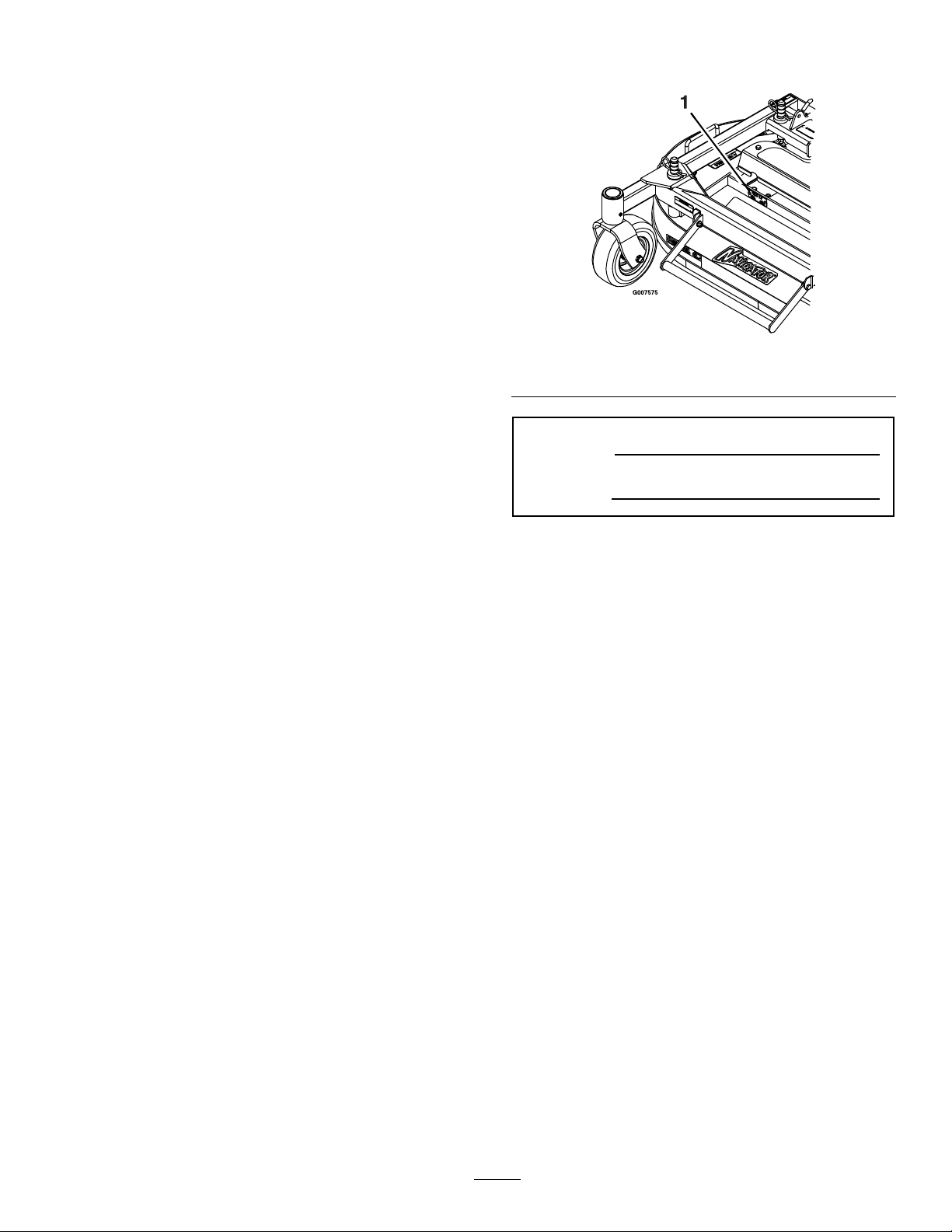
Figure1
1.Modelandserialnumberlocation
ModelNo.
SerialNo.
Wheneveryouneedservice,genuineExmarkparts,
oradditionalinformation,contactanAuthorized
ServiceDealerorExmarkCustomerServiceandhave
themodelandserialnumbersofyourproductready .
Figure1identiesthelocationofthemodelandserial
numbersontheproduct.Writethenumbersinthe
spaceprovided.
3
Page 4

Contents
Introduction...........................................................3
Safety.....................................................................5
SafetyAlertSymbol.........................................5
SafeOperatingPractices..................................5
SafetyandInstructionalDecals.......................7
Specications.........................................................8
ModelNumbers..............................................8
Systems...........................................................8
Dimensions.....................................................8
TorqueRequirements......................................8
Setup......................................................................9
AssembleDecktoNavigator...........................9
DeckRemoval...............................................10
ProductOverview................................................11
Operation.............................................................11
AdjustingtheCuttingHeight.........................11
DeckRaisingandLowering...........................11
AdjustingFillReductionSystem(FRS)
Bafes.......................................................12
Maintenance.........................................................14
RecommendedMaintenanceSchedule(s)...........14
PeriodicMaintenance.......................................14
CheckMowerBlades.....................................14
CheckforLooseHardware............................15
CheckTirePressures.....................................15
ChangeGearboxOil......................................15
LubricateGreaseFittings...............................16
LubricateCasterWheelHubs........................16
ThreadLockingAdhesives.............................17
Adjustments.....................................................18
DeckLeveling...............................................18
CasterPivotBearingsPre-load
Adjustment...............................................18
DeckLockingPinStopAdjustment...............18
Cleaning...........................................................19
CleanDebrisFromCuttingDeck...................19
CleanGrassBuild-UpUnderDeck................19
Troubleshooting...................................................20
4
Page 5
Safety
Safety
SafetyAlertSymbol
ThisSafetyAlertSymbol(Figure2)isusedbothin
thismanualandonthemachinetoidentifyimportant
safetymessageswhichmustbefollowedtoavoid
accidents
Thissymbolmeans:ATTENTION!BECOME
ALERT!YOURSAFETYISINVOLVED!
Figure2
1.Safetyalertsymbol
Thesafetyalertsymbolappearsaboveinformation
whichalertsyoutounsafeactionsorsituations
andwillbefollowedbythewordDANGER,
WARNING,orCAUTION.
DANGER:Whitelettering/Redbackground.
Indicatesanimminentlyhazardoussituationwhich,if
notavoided,Willresultindeathorseriousinjury.
WARNING:Blacklettering/Orangebackground.
Indicatesapotentiallyhazardoussituationwhich,if
notavoided,Couldresultindeathorseriousinjury.
CAUTION:Blacklettering/Yellowbackground.
Indicatesapotentiallyhazardoussituationwhich,if
notavoided,Mayresultinminorormoderateinjury.
•Neverletchildrenoruntrainedpeopleoperate
orservicetheequipment.Localregulationsmay
restricttheageoftheoperator.
•Theowner/usercanpreventandisresponsible
foraccidentsorinjuriesoccurringtohimselfor
herself,otherpeopleorproperty.
Preparation
•DoNotmodifytheNavigatorcuttingdeck.
•OnlyuseonmachinesapprovedbyExmark.
•Wearappropriateclothingincludingsafetyglasses,
substantialfootwear,longtrousers,andhearing
protection.DoNotoperatewhenbarefootor
whenwearingopensandals.
CAUTION
Thismachineproducessoundlevelsin
excessof85dBAattheoperator’searand
cancausehearinglossthroughextended
periodsofexposure.
Wearhearingprotectionwhenoperatingthis
machine.
•Inspecttheareawheretheequipmentistobe
usedandremoveallrocks,toys,sticks,wires,
bones,andotherforeignobjectswhichcanbe
thrownbythemachineandmaycausepersonal
injurytotheoperatororbystanders.
Thismanualusestwootherwordstohighlight
information.Importantcallsattentiontospecial
mechanicalinformationandNoteemphasizes
generalinformationworthyofspecialattention.
SafeOperatingPractices
Training
•ReadthetractorandcuttingdeckOperator’s
Manualsandothertrainingmaterial.Ifthe
operator(s)ormechanic(s)cannotreadEnglish
itistheowner’sresponsibilitytoexplainthis
materialtothem.
•Becomefamiliarwiththesafeoperationofthe
equipment,operatorcontrols,andsafetysigns.
•Alloperatorsandmechanicsshouldbetrained.
Theownerisresponsiblefortrainingtheusers.
Operation
•Operateonlyindaylightorgoodarticiallight,
keepingawayfromholesandhiddenhazards.
•Neverraisedeckwithbladesrunning.
•Stopengine,waitforallmovingpartstostop,
removekeyandengageparkingbrake:
–Beforechecking,cleaningorworkingonthe
mower.
–Afterstrikingaforeignobjectorabnormal
vibrationoccurs(inspectthemowerfor
damageandmakerepairsbeforerestarting
andoperatingthemower).
–Beforeclearingblockages.
–Wheneveryouleavethemower.
5
Page 6

Safety
WARNING
Hands,feet,hair,clothing,oraccessoriescan
becomeentangledinrotatingparts.Contact
withtherotatingpartscancausetraumatic
amputationorseverelacerations.
•DoNotoperatethemachinewithout
guards,shields,andsafetydevicesin
placeandworkingproperly.
•Keephands,feet,hair,jewelry,orclothing
awayfromrotatingparts.
•Stoptheblades,slowdown,andusecautionwhen
crossingsurfacesotherthangrassandwhen
transportingthemowertoandfromtheareato
bemowed.
•Bealert,slowdownandusecautionwhenmaking
turns.Lookbehindandtothesidebefore
changingdirections.
MaintenanceandStorage
•DisengagePTO ,setparkingbrake,stopengine
andremovekeyordisconnectsparkplugwire.
Waitforallmovementtostopbeforeadjusting,
cleaningorrepairing.
•Usecarewhencheckingblades.Wraptheblade(s)
orweargloves,andusecautionwhenservicing
them.Onlyreplacedamagedblades.Never
straightenorweldthem.
•Keepallguards,shieldsandallsafetydevicesin
placeandinsafeworkingcondition.
•Checkallboltsfrequentlytomaintainproper
tightness.
•Frequentlycheckforwornordeteriorating
componentsthatcouldcreateahazard.
•Allreplacementpartsmustbethesameas
orequivalenttothepartssuppliedasoriginal
equipment.
6
Page 7
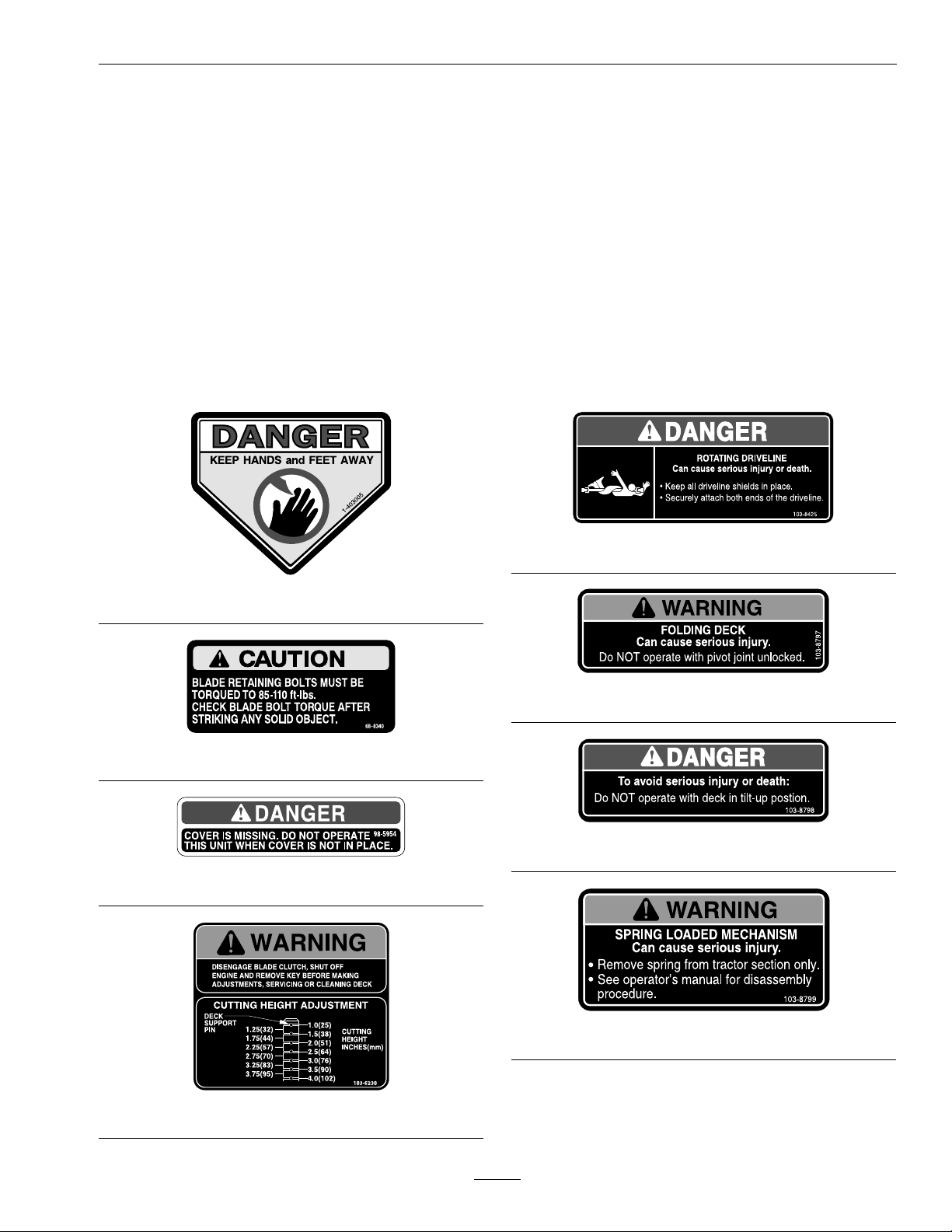
SafetyandInstructionalDecals
Safety
•Keepallsafetysignslegible.Removeallgrease,
dirtanddebrisfromsafetysignsandinstructional
labels.
•Replaceallworn,damaged,ormissingsafety
signs.
•Whenreplacementcomponentsareinstalled,be
surethatcurrentsafetysignsareafxedtothe
replacedcomponents.
•Ifanattachmentoraccessoryhasbeeninstalled,
makesurecurrentsafetysignsarevisible.
1-403005
•Newsafetysignsmaybeobtainedfrom
yourauthorizedExmarkequipmentdealeror
distributororfromExmarkMfg.Co.Inc.
•Safetysignsmaybeafxedbypeelingoffthe
backingtoexposetheadhesivesurface.Apply
onlytoaclean,drysurface.Smoothtoremove
anyairbubbles.
•Familiarizeyourselfwiththefollowingsafetysigns
andinstructionlabels.Theyarecriticaltothesafe
operationofyourExmarkcommercialmower.
103-8425
103-8797
68-8340
103-8798
98–5954
103-8799
103-6230
7
Page 8

Specications
Specications
ModelNumbers
SerialNos:790,000andHigher
CD42CD;CD48CD
Systems
Tires&Wheels
Quantity
Tread
Size8x3.00–4
PlyRating
Pressure
CuttingDeck
•ModelNumbers:
–CD42CD
–CD48CD
•CuttingWidth:
–42inchDeck:42inch(106.7cm)
–48inchDeck:48inch(121.9cm)
–48inchDeck:45/8inches(11.7cm)
•CuttingHeightAdjustment:
Adjustsfrom1inch(2.5cm)to4inches(10.2cm)
FrontCaster
Semi-Pneumatic
2
Smooth
in1/4inch(.64cm)increments.
•MulchingKit:Optional
Dimensions
OverallWidth:
42inchDeck48inchDeck
43.2inches(109.7cm)49.2inches(125.0cm)
OverallLength:
42inchDeck48inchDeck
37.2inches(94.4cm)39.9inches(101.3cm)
OverallHeight:
•Discharge:Center
•BladeSize:(2ea.)
–42inchDeck:22.00inches(55.9cm)
–48inchDeck:25.00inches(63.5cm)
•DeckDrive:
–Clutchingbeltonhorizontalengineshaft.
Dual“A”sectionhexagonbeltwithspring
tensionedidlertojackshaftandblower.
–Heavy-dutycastiron,spiralbevelgearboxis
naldrivetoblades.
•Deck:
Fulloatingdeckisattachedtoout-frontsupport
frame.Deckdesignallowsforbaggingor
mulching.
•DeckDepth:
–42inchDeck:45/8inches(11.7cm)
42inchDeck48inchDeck
13.1inches(33.3cm)13.1inches(33.3cm)
CurbWeight:
42inchDeck48inchDeck
295lb(134kg)325lb(147kg)
TorqueRequirements
BoltLocation
BladeMountingBolt85-110ft-lb(115-149N-m)
GearboxMountingBolts30-35ft-lb(41-47N-m)
GearboxAssemblyBolts50-55ft-lb(68-75N-m)
BladeShearBolts80-100in-lb
8
Torque
(922-1130N-cm)
Page 9

Setup
WARNING
OperatingaNavigatortractorwithoutan
approvedExmarkfrontmountattachment
increasesthepossibilityofoperator
entanglementindrivewheelsorforwardtip
over.Entanglementortip-overcouldcause
seriousinjuryordeath.
WhenoperatingaNavigatortractor
withoutanapprovedExmarkfrontmount
attachment,observethefollowing:
•Keepfeetandclothingawayfromtires.
•Limitoperationtominimumrequiredto
installadifferentfrontmountattachment.
•Minimizespeedanduseextremecaution.
•Onlyoperateonaatlevelsurface.
•DoNotoperateupordownatrailerramp.
Setup
Figure3
1.Jackshaft2.Driveshaft
4.Aligndeckpusharmtubestotractorpusharms
andpushdeckrearward.Securepusharmswith
lynchpinsonleftandrightsidesoftheunit(see
Figure4).
•Avoidsuddenaccelerationordeceleration.
AssembleDecktoNavigator
Important:DoNottransportNavigatortractor
withoutandapprovedExmarkfrontmount
attachment.
1.Stopengine,waitforallmovingpartstostopand
removekey.Engageparkingbrake.
2.RollthemowerdeckuptotheNavigatortractor
withthedischargetubedown,makingsurethe
deckspringsarelocatedabovethedrivewheel
andbelowtheconsoleoneachside.
3.Raiseseatandinstalldriveshaftontojackshaft
(seeFigure3)
Figure4
1.Slidethepusharmintothedeckpusharmtube
2.Securethepushpinarmwithlynchpin
5.AlignupperportionofthePTOrubberguardto
thetabsonthefrontoftheconsoleandsecure
withaclevispinandhairpinoneachside(see
Figure5).
9
Page 10

Setup
DeckRemoval
1.Stopengine,waitforallmovingpartstostop,and
removekey.Engageparkingbrake.
2.Raisemowerdeckupandlatchwithdecklocking
pinsperRaisingtheMowerDecktothe
ServicePositionsectioninOperation.
3.Removehairpinsandwashersatthetopofthe
deckliftassistspringoneachsideoftheunit(see
Figure6).
Figure5
1.SecurePTOguardwithclevispinandhairpin
6.Releasethedecklockingpinsoneachside,raise
mowerdecktotheservicepositionandsecure
decklatchontohook.SeeRaisingtheDeckto
theServicePositionsectioninOperation.
7.Installspringsontothespringanchorpinsunder
theleftandrightconsolesandsecurewitha
washerandhairpin(seeFigure6).
4.Removethespringfromthespringanchor.
Repeatforothersideofunit.
5.Un-latchdeckfromraisedpositionandslowly
lowerdecktogroundperLoweringtheMower
DecktotheOperationPositionsectionin
Operation.
Note:Deckwillbecomeheavieroncespringsare
removedfromtheanchors.Lowerdeckcarefully.
6.Removelynchpinsatfrontofpusharmsonboth
sidesoftheunit(seeFigure4).
7.Removehairpinandclevisfrombothsidesofthe
PTOguard(seeFigure5).
8.Raiseseatanddisconnectdriveshaftusingquick
coupleratjackshaft(seeFigure3).
9.Pullmowerdeckforwardtoremovefromunit.
Important:DoNottransportNavigator
tractorwithoutanapprovedExmarkfront
mountattachment.
Figure6
1.Springanchorpinunderconsole
2.Securespringswithawasherandhairpin
3.Slidespringontospringanchorpin
8.Un-latchdeckfromraisedposition,slowlylower
decktogroundandlockdecklockingpinson
eachsideLoweringtheDecktotheOperation
PositionsectioninOperation.
10
Page 11

Operation
ProductOverview
Figure7
1.Cutheightadjustment3.Decklifthandle
2.Casterwheel
Operation
AdjustingtheCuttingHeight
Thecuttingheightofthemowerdeckisadjusted
from1to4inches(2.5cmto10.2cm)in1/4inch
(.63cm)increments.
1.Stopthemachineandmovethespeedcontrol
leverstotheneutralposition.
2.DisengagethePTO.
3.Engagetheparkbrake.
4.Stoptheengine,removethekeyandwaitforall
movingpartstostop.
5.Movecotterpinsonfourdecksupportpinsto
properholeforheightofcutdesired.
DeckRaisingandLowering
RaisingtheMowerDeckintoService
Position
1.Stopengine,waitforallmovingpartstostopand
removekey.Engageparkingbrake.
WARNING
Incorrectlyraisingorloweringamowerdeck
canbedangerous.Adroppedmowerdeck
canresultinaseriousinjuryorproperty
damage.
•Alwaysraiseandlowerdeckonat,dry
ground,freeofanyobstructions.
•Firmlygraspthedecklifthandleand
lowerinaslowcontrolledmanner.
•Alwaysmakesurethedeckissecurely
latchedinthe“up”or“down”position.
2.Releasethedecklockingpinsoneachside
(Figure8).
11
Page 12

Operation
Figure8
1.Decklifthandle
2.Rotatethedecklockingpintowardtherearandpull
outwardtounlock.
3.Pushthedecklockingpininandrotatetowardthefront
tolock.
WARNING
Operatingthemowerdeckintheraised
servicepositioncanbedangerous.Engaging
thePTOwithadeckintheraisedposition
canresultinaseriousinjuryorproperty
damage.
Alwayslowerandlockmowerdeckinthe
operationpositionbeforeengagingthePTO.
LoweringtheMowerDecktothe
OperatingPosition
1.Whilermlyholdingontodecklifthandle,
unhookdecklatchfromtractorsectionandslowly
lowerdecktoground(seeFigure9).
2.Pushdecklockingpinsinwardandrotateforward
tosecurelylockdeckinloweredposition(see
Figure8).
3.Usingdecklifthandle,liftdeckupandlatchin
“up”position(latchislocatedatfrontcenterof
seat)(seeFigure9).
Figure9
1.Securethedeckin
theraisedpositionby
securingthedecklatch
ontothehook.
2.Hook
WARNING
Operatingmowerwithoutlockingpins
securelylatchedcanresultinthemowerdeck
foldingupunexpectedly.Themowerdeck
foldingupunexpectedlycancauseserious
injury.
Alwaysoperatemowerwithlockingpins
securelylatched.
AdjustingFillReduction
System(FRS)Bafes
TheNavigator’sexclusiveFillReductionSystemhas
beendesignedtoallowyoutoreducetheamountof
clippingscollectedbyvaryingdegrees.
Advantagesincludelessfrequentemptyingofthe
hopperandreturnofnutrientstothesoil.
PossibleCongurations:
1.Bafesopen,standardblades–Maximum
collection
2.Bafesclosed,standardblades–Partialmulching
3.Bafesclosed,mulchblades–Intermediate
mulching
4.Mulchpluginstalled,mulchblades–Complete
mulching(requiresmulchkit)
12
Page 13

ToadjusttheFRSbafes:
1.Stopengine,waitforallmovingpartstostopand
removekey.Engageparkingbrake.
2.Removehairpinsandclevispinsfrombothsides
ofthePTOguard(seeFigure5).Foldguard
forward.
3.LoosennylocnutsontherearstudsoftheFRS
bafes.
Operation
Figure10
1.PTOguardremovedfor
clarity
2.Loosennylocnuts
4.RaisedeckasstatedinRaisingtheMowerDeck
totheServicePositionsection.
5.Removeboltandwasheratthefrontofeach
oftheFRSbafes.Rotatebafesintodesired
positionandreinstallboltandwasher.
Figure11
1.Bafesshowninclosedposition
2.Bafesshowninopenposition
3.Bolt
4.Washer
5.Bafes
6.LowerdeckperLoweringtheMowerDeckto
theOperatingPositionsection.
7.SnugnylocnutsontherearstudsoftheFRS
bafes.Thesenutsmaybeleftslightlylooseif
frequentbafeadjustmentisanticipated.
8.ReinstallPTOguardusingclevispinsandhair
pinsremovedinstep2.
13
Page 14

Maintenance
Maintenance
Note:Determinetheleftandrightsidesofthemachinefromthenormaloperatingposition.
WARNING
Whilemaintenanceoradjustmentsarebeing
made,someonecouldstarttheengine.
Accidentalstartingoftheenginecould
seriouslyinjureyouorotherbystanders.
Removethekeyfromtheignitionswitch,
engageparkingbrake,andpullthewire(s)
offthesparkplug(s)beforeyoudoany
maintenance.Alsopushthewire(s)aside
soitdoesnotaccidentallycontactthespark
plug(s).
RecommendedMaintenanceSchedule(s)
MaintenanceService
Interval
Aftertherst50hours
Beforeeachuseordaily
Every40hours
Every100hours
Yearly
MaintenanceProcedure
•Changeoilinallthreegearboxhousings.Addoilasneededuntillevelwithoildrainplug.
•Checkthemowerblades.
•Checkforloosehardware.
•Greasethefrontcasterwheelhub.
•Cleanthegrassanddebrisbuild-upfromthecuttingdeck.
•Cleanthegrassbuild-upfromunderthedeck.
•Checktheconditionofthebelts.
•Greasethedriveshaft.
•Changeoilinallthreegearboxhousings.Addoilasneededuntillevelwithoildrainplug.
thereafter
•Greasethedeckip-up.
•Greasethepivotarmtubes.
•Greasethefrontcasterpivots.
•Lubricatethecasterwheelhubs.
PeriodicMaintenance
CheckMowerBlades
ServiceInterval:Beforeeachuseordaily
1.Stopengine,waitforallmovingpartstostop,and
removekey.Engageparkingbrake.
2.Liftdeckandsecureinraisedpositionasstated
insectionRaisingtheMowerDecktothe
ServicePosition.
3.Inspectbladesandsharpenorreplaceasrequired.
4.Toremoveblade,useablockofwoodorlocking
plierstoholdbladeinplaceandremovethe
1/2-20x21/4inchbladeboltthatsecuresthe
bladeandbladedriver.
5.Re-installthebladedriver(withnewblades)by
usingablockofwoodorlockingplierstohold
thebladeinplaceandtorquethebladeboltsto
85-110ft-lb(115-149N-m).
14
Page 15

Maintenance
Note:Bladedriveratsmustbealignedwiththe
atsontheshaftwheninstallingbladeonthe
mowerdeck.
6.Lowerthemowerdecktotheoperationposition
(seesectionLoweringtheMowerDecktothe
OperationPosition).
WARNING
Operatingamowerdeckwithlooseor
weakenedbladeboltscanbedangerous.A
looseorweakenedbladeboltcouldallowa
bladerotatingatahighspeedtocomeout
fromunderthedeck,causingseriousinjury
orpropertydamage.
•Replacethebladeboltafterstrikinga
foreignobject.
•UseonlygenuineExmarkreplacement
parts.
•DoNotlubricatethethreadsofthebolt
orspindlebeforeassembly.
•Torquethebladeboltto85-110ft-lb
(115-149N-m).
•Torquetheshearboltsto80-100in-lb
(922-1130N-cm).
CheckforLooseHardware
ServiceInterval:Beforeeachuseordaily
1.Stopengine,waitforallmovingpartstostop,and
removekey.Engageparkingbrake.
2.Visuallyinspectmachineforanyloosehardware
oranyotherpossibleproblem.Tightenhardware
orcorrecttheproblembeforeoperating.
CheckTirePressures
ServiceInterval:Every40hours
Thefrontcastertiresaresemi-pneumaticandDo
Notneedtobeinated.
Note:DoNotaddanytypeoftirelinerorfoam
llmaterialtothetires.Excessiveloadscreatedby
foamlledtiresmaycausefailurestothehydrodrive
system,frame,andothercomponents.Foamlling
tireswillvoidthewarranty.
ChangeGearboxOil
ServiceInterval:Aftertherst50hours
Every100hoursthereafter
1.Stopengine,waitforallmovingpartstostop,and
removekey.Engageparkingbrake.
Figure12
1.1/2-20x21/4bladebolt—torqueto85-110ft-lb
(115-149N-m).
2.Washer
3.Shearbolts—torqueto80–100in-lb(922-1130N-cm)
4.Bladedriver
5.1/4-20nylocnuts
2.Placeunitonalevelsurface.
3.Removethegearboxanddriveshaftassembly
fromthemowerdeck.Retainhardwareforre-use.
4.Removethelargeoildrainplugonthefrontof
eachofthethreegearboxsectionsanddrainoil
(Figure13).
Figure13
1.Smallmagneticplugs
(frontandback)
2.Largeoildrain/llplug
3.Smallmagneticplug
(frontonly)
15
Page 16

Maintenance
5.Removesmallmagneticplugsandwipeawayany
materialaccumulatedontheplugs.
6.ApplyaTeonpipesealanttoallsmallmagnetic
plugsandre-installintothegearbox.
7.Re-installthegearboxanddriveshaftassembly
tothemowerdeck.
8.FillgearboxwithMobilSHC(synthetic)75W -90
gearlubeoiluntillevelwithoildrain/llplug.
Eachofthegearboxsectionsmustbelled
separately.
Note:Mowerdeckshouldremainleveltothe
groundwhenllinggearboxwithoil.DoNotll
gearboxwithdeckraisedintheserviceposition.
9.ApplyaTeonpipesealanttothe3largeoilplugs
andre-installintothegearbox.
LubricateGreaseFittings
Note:Seechartforserviceintervals.
1.Stopengine,waitforallmovingpartstostop,and
removekey.Engageparkingbrake.
2.LubricatettingswithNGLIgrade#2
multi-purposegungrease.
Refertothefollowingchartforttinglocations
andlubricationschedule.
LubricationChart
Fitting
Locations
1.Drive
Shaft
2.Front
Caster
WheelHub
3.Deck
Flip-Up
4.Push
ArmTubes
5.Front
Caster
Pivots
Initial
Pumps
1
128Hours
1
12
*0
Numberof
Places
340Hours
4100Hours
2
Service
Interval
100Hours
*Yearly
3.Lubricatecasterpivotsonceayear.Removehex
plugandcap.Threadgreasezerkinholeand
pumpwithgreaseuntilitoozesoutaroundtop
bearing.Removegreasezerkandthreadplugback
in.Placecapbackon.
LubricateCasterWheelHubs
ServiceInterval:Yearly
1.Stopengine,waitforallmovingpartstostop,and
removekey.Engageparkingbrake.
Figure14
1.Sealguard2.Spacernutwithwrench
ats
2.Removecasterwheelfromcasterforks.
*Seestep3forspeciallubricationinstructionson
thefrontcasterpivotsandtheLubricateCaster
WheelHubssectionforspeciallubrication
instructionsonthefrontcasterswheelhubs.
3.Removesealguardsfromthewheelhub.
4.Removeoneofthespacernutsfromtheaxle
assemblyinthecasterwheel.Notethatthread
lockingadhesivehasbeenappliedtolockthe
16
Page 17

Maintenance
spacernutstotheaxle.Removetheaxle(with
theotherspacernutstillassembledtoit)from
thewheelassembly.
5.Pryoutseals,andinspectbearingsforwearor
damageandreplaceifnecessary.
6.PackthebearingswithaNGLIgrade#1
multi-purposegrease.
7.Insertonebearing,onenewsealintothewheel.
Note:Seals(ExmarkPN103-0063)mustbe
replaced.
8.Iftheaxleassemblyhashadbothspacernuts
removed(orbrokenloose),applyathreadlocking
adhesivetoonespacernutandthreadontothe
axlewiththewrenchatsfacingoutward.Do
Notthreadspacernutallofthewayontotheend
oftheaxle.Leaveapproximately1/8inch(3mm)
fromtheoutersurfaceofthespacernuttothe
endoftheaxleinsidethenut.
9.Inserttheassemblednutandaxleintothewheel
onthesideofthewheelwiththenewsealand
bearing.
ThreadLockingAdhesives
Threadlockingadhesivessuchas“Loctite242”
or“Fel-Pro,Pro-LockNutType”areusedonthe
followingfasteners:
Casterwheelspacernuts.
10.Withtheopenendofthewheelfacingup,ll
theareainsidethewheelaroundtheaxlefullof
NGLIgrade#1multi-purposegrease.
11.Insertthesecondbearingandnewsealintothe
wheel.
12.Applyathreadlockingadhesivetothe2ndspacer
nutandthreadontotheaxlewiththewrenchats
facingoutward.
13.Torquethenutto75-80in-lb(8-9N-m),loosen,
thenre-torqueto20-25in-lb(2-3N-m).Make
sureaxledoesnotextendbeyondeithernut.
14.Reinstallthesealguardsoverthewheelhuband
insertwheelintocasterfork.Reinstallcasterbolt
andtightennutfully.
Important:Topreventsealandbearingdamage,
checkthebearingadjustmentoften.Spinthe
castertire.Thetireshouldnotspinfreely
(morethan1or2revolutions)orhaveanyside
play.Ifthewheelspinsfreely,adjusttorqueon
spacernutuntilthereisaslightamountofdrag.
Reapplythreadlockingadhesive.
17
Page 18

Maintenance
Adjustments
Note:DisengagePTO,shutoffengine,waitfor
allmovingpartstostop,engageparkingbrake,and
removekeybeforeservicing,cleaning,ormakingany
adjustmentstotheunit.
DeckLeveling
1.Positionmoweronaatsurface.
2.Stopengine,waitforallmovingpartstostop,and
removekey.Engageparkingbrake.
3.Inatedrivetiresto15psi(103kPa).
4.Verifyallhairpinsareinthe3inchdeckheight
holeswiththespacersunderthehairpins
(Figure15).
Figure16
1.Springdiscwashers
DeckLockingPinStop
Adjustment
Figure15
RightHandSideShown
1.Hairpin3.Decksupportpin
2.Spacer
5.Shorten/lengtheneachdecksupportpintoobtain
bladetipheightof3inchesatthefrontofthe
deckand31/4inchesattherearofthedeck.
1.Slidedecklockingpinsinonbothsidesandrotate
tolockthedeckinthe“operation”position.
2.Loosenthejamnutandturnthestopscrew
clockwiseuntilthelockingpinsistightandcannot
berotatedbyhand(Figure17).
Figure17
1.Rotatestopscrewclockwiseuntillockingpinistight,
thenbackoff1/2turn.
2.Loosenjamnut
CasterPivotBearings
Pre-loadAdjustment
Removedustcapfromcasterandtightennylocnut
untilwashersareat.Backthenylocoff1/4ofa
turntoproperlysetthepre-loadonthebearings.
Note:Ifdisassembled,makesurethespringwashers
arereinstalledasshowninFigure16.
3.Loosenthestopscrewcounterclockwise1/2
turnandtightenthejamnut
4.Testthelockingpintomakesureitslidesfreely .
Readjustifnecessary.
18
Page 19

Cleaning
CleanDebrisFromCutting
Deck
ServiceInterval:Beforeeachuseordaily
1.Stopengine,waitforallmovingpartstostop,and
removekey.Engageparkingbrake.
2.Cleanoffanyoil,debris,orgrassbuild-uponthe
cuttingdeck,especiallyunderdeckbeltshields.
CleanGrassBuild-UpUnder
Deck
ServiceInterval:Beforeeachuseordaily
1.Stopengine,waitforallmovingpartstostop,and
removekey.Engageparkingbrake.
Maintenance
2.Raisemowerdeckandsecureinlatchedposition
(seeRaisingtheMowerDecktotheService
PositionsectioninOperation).
3.Cleanoutanygrassbuild-upfromundersideof
deckandindischargechute.
4.Lowerdecktocuttingpositionandlockdeck
lockingpins(seeLoweringtheMowerDeckto
theOperationPositionsectioninOperation.
19
Page 20

Troubleshooting
Troubleshooting
Important:Itisessentialthatalloperatorsafetymechanismsbeconnectedandinproperoperating
conditionpriortomoweruse.
Whenaproblemoccurs,donotoverlookthesimplecauses.Forexample:startingproblemscouldbecaused
byanemptyfueltank.
Thefollowingtablelistssomeofthecommoncausesoftrouble.DoNotattempttoserviceorreplacemajor
itemsoranyitemsthatcallforspecialtimingofadjustmentsprocedures(suchasvalves,governor,etc.).Have
thisworkdonebyyourEngineServiceDealer.
Note:WhendisconnectingelectricalconnectorsDoNotpullonthewirestoseparatetheconnectors.
ProblemPossibleCauseCorrectiveAction
Unevencuttingheight.
Abnormalvibration.
BladesDoNotrotate.
1.Blade(s)notsharp.1.Sharpentheblade(s).
2.Cuttingblade(s)is/arebent.
3.Mowerdeckisnotlevel.3.Levelmowerdeckfromside-to-sideand
4.Undersideofmowerisdirty.4.Cleantheundersideofthemower.
5.Tirepressureindrivetiresnotcorrect.5.Adjusttirepressureinthedrivetires.
6.Spacersareinwronglocation.
7.Tipsofadjacentbladesareatanuneven
cuttingheight.Bladestipsshouldbeeven
within3/16inchwhichisapproximately
onebladethickness.
1.Cuttingblade(s)is/arebentorunbalanced.
2.Blademountingboltisloose.2.Tightentheblademountingbolt.
3.Enginemountingboltsareloose.3.Tightentheenginemountingbolts.
4.Enginepulleyisdamaged.4.ContactanAuthorizedServiceDealer.
5.Bladespindleisbent.5.ContactanAuthorizedServiceDealer.
1.PTObeltisworn,loose,orbroken.1.Checkbelttensionorreplacebelt
2.PTOshaftisnotconnected.
3.PTObeltisoffpulley .3.Checkbeltfordamage.Installbeltand
2.Installnewcuttingblade(s).
front-to-rear.
6.Positionspacersunderhairpins.
7.Replaceblades,spindlesand(or)check
fordamagetomowerdeck.
1.Installnewcuttingblade(s).
2.ConnectPTOshaft.
checkadjustingshaftsandbeltguidesfor
correctposition.
20
Page 21

Conditions and Products Covered
Exmark Mfg. Co. Inc. and its affiliate, Exmark Warranty
Company, pursuant to an agreement between them, jointly
warrant on the terms and conditions herein, that we will repair,
replace or adjust any part on these products and found by us
(in the exercise of our reasonable discretion) to be defective in
factory materials or workmanship for a period of two years.
This warranty applies to Exmark commercial turf equipment
sold in the U.S. or Canada. This warranty may only be
assigned or transferred to a second (or third) owner by an
authorized Exmark dealer. The warranty period commences
upon the date of the original retail purchase.
Warranty Exceptions Warranty Period
• Bags, Belts and Tires 90 days
• Battery 1 Year Prorated
• Engine 2 years*
* The Engine warranty is covered by the engine manufacturer.
Please refer to the engine manufacturer’s warranty statement
that is included in the literature packet.
This warranty only includes the cost of parts and labor.
Items and Conditions Not Covered
This warranty does not cover the following:
• Pickup and delivery charges to and from any authorized
Exmark Service Dealer.
• Any damage or deterioration due to normal use, wear and
tear, or exposure.
• Cost of regular maintenance service or parts, such as filters,
fuel, lubricants, tune-up parts, and adjustments.
• Any product or part which has been altered or misused or
required replacement or repair due to normal wear,
accidents, or lack of proper maintenance.
• Any repairs necessary due to use of parts, accessories or
supplies, including gasoline, oil or lubricants, incompatible
with the turf equipment or other than as recommended in
the operator's manual or other operational instructions
provided by Exmark.
There are no other express warranties except for engine and
special emission system coverage.
All warranty work must be performed by an authorized
Exmark Service Dealer using Exmark approved replacement
parts.
Instructions for Obtaining Warranty Service
The product must be registered with original proof of purchase
by an Exmark Service Dealer before obtaining any warranty
service.
Contact any Exmark Service Dealer to arrange service at their
dealership. To locate a dealer convenient to you, access our
website at www.exmark.com. U.S. or Canada customers may
also call 402-223-6375.
If for any reason you are dissatisfied with the Service Dealer’s
analysis or with the assistance provided, contact us at:
Exmark Customer Service Department
The Exmark Warranty Company
2101 Ashland Avenue
Beatrice, NE 68310
402-223-6375 or
service@exmark.com
Owner’s Responsibilities
The Exmark turf equipment, including any defective part,
must be returned to an authorized Exmark service dealer
within the warranty period. This warranty extends only to turf
equipment operated under normal conditions. You must read
the operator’s manual. You must also properly service and
maintain your Exmark product as described in the operator’s
manual. Such routine maintenance, whether performed by a
dealer or by you, is at your expense.
General Conditions
The sole liability of Exmark and Exmark Warranty Company
with respect to this warranty shall be repair or replacement of
defective components as set forth herein. Neither Exmark
nor Exmark Warranty Company shall be liable for any
incidental or consequential loss or damage.
Such damages include but are not limited to:
• Expenses related to gasoline, oil or lubricants.
• Travel time, overtime, after hours time or other
extraordinary repair charges or charges relating to repairs or
replacements outside of normal business hours at the place
of business of the authorized Exmark Service Dealer.
• Rental of like or similar replacement equipment during the
period of any warranty, repair or replacement work.
• Any telephone or telegram charges or travel charges.
• Loss or damage to person or property other than that
covered by the terms of this warranty.
• Any claims for lost revenue, lost profit or additional cost as
a result of a claim of breach of warranty.
• Attorney's fees.
No Claim of breach of warranty shall be cause for cancellation
or rescission of the contract of sale of any Exmark mower.
All implied warranties of merchantability (that the
product is fit for ordinary use) and fitness for use (that the
product is fit for a particular purpose) are limited to the
duration of the express warranty.
Some states do not allow exclusions of incidental or
consequential damages, or limitations on how long an
implied warranty lasts, so the above exclusions and
limitations may not apply to you.
This warranty gives you specific legal rights, and you may
also have other rights which vary from state to state.
Exmark Commercial Turf Equipment
2 Year Limited Warranty
G4500-425
21
Page 22

ServiceRecord
Date:
DescriptionofWorkDone:ServiceDoneBy:
22
Page 23

23
Page 24

MI D-MOUNT RIDING ACCE SSORIES AND OPTIONS
SEE EXMARK’S COMPLETE LINE OF ACCESSORIES AND OPTIONS
WALK-BEHIND ACCESSORIES AND OPTIONS
GRASS CATCHER
MICRO-MULCH SYSTEM
TURF STRIPER
STANDON
CUSTOM RIDE SEAT SUSPENSION SYSTEM
FULL SUSPENSION SEAT
DECK LIFT ASSIST KIT
HITCH KIT
LIGHT KIT
12
V POWER PORT
MICRO-MULCH SYSTEM
OPERATOR CONTROLLED DISCHARGE
ROLL OVER PROTECTION SYSTEM (ROPS)
SUN SHADE
TRASH CONTAINER
TURF STRIPER
ULTRA VAC COLLECTION SYSTEM
ULTRA VAC QUICK DISPOSAL SYSTEM
OU T-FRO NT RIDING ACCESSORI ES AND OPTI ONS
CUSTOM RIDE SEAT SUSPENSION SYSTEM
DUAL-TAIL WHEEL
FLOOR PAN EXTENDER
HITCH KIT
LIGHT KIT
MICRO-MULCH SYSTEM
ROLL OVER PROTECTION SYSTEM (ROPS)
SNOW BLADE
SNOWBLOWER
SUN SHADE
TRASH CONTAINER
ULTRA VAC COLLECTION SYSTEM
ULTRA VAC QUICK DISPOSAL SYSTEM
WEATHER CAB
PlaceModelNo.andSerialNo.
LabelHere(IncludedintheLiterature
Pack)orFillinBelow
ModelNo.
SerialNo.
©2009ExmarkMfg.Co.,Inc.
IndustrialParkBox808
Beatrice,NE68310
AllRightsReserved
DatePurchased
PartNo.4500-370Rev.A
(402)223-6300
Fax(402)223-5489
PrintedintheUSA
www.exmark.com
 Loading...