

Page 1

EXMARK V-TWIN AIR COOLED
ENGINE SERVICE MANUAL
P/N 127-9041 (708cc)
Page 2

About this Manual
This service manual was written expressly for
Exmark service technicians. Exmark Mfg. Co. Inc.
has made every effort to make the information in
this manual complete and correct. Basic shop safety
knowledge and mechanical/electrical skills are
assumed. The Table of Contents lists the systems
and the related topics covered in this manual. An
electronic version of this service manual is available
on the Exmark Dealer Extranet. We are hopeful that
you will find this manual a valuable addition to your
service shop. If you have any questions or
comments regarding this manual, please contact us
at the following address:
Exmark Mfg. Co. Inc.
2101 Ashland Ave.
Beatrice, NE 68357
Customer Service All Call: 402-223-6375
e-mail - service@exmark.com
NOTES:
Page 3

Maintenance
Chapter 1 – General Service Information
1
Chapter 2 - Specifications
2
Chapter 3 - Engine Service and Maintenance
3
Chapter 4 – Engine Disassembly and Service
4
Chapter 5 - Electrical
5
– General Service Information
Safety
Safety Precautions
Service Rules
Engine Model / Serial Number Location
Torque Values
Engine Specifications
General Torque Specifications
Safety
Safety Information
Chapter 1
This symbol means WARNING or PERSONAL SAFETY INSTRUCTION – read the instruction because it has to do with
your safety. Failure to comply with the instruction may result in personal injury or even death.
This manual is intended as a service and repair manual only. The safety instructions provided herein are for
troubleshooting, service, and repair of the Toro engine. The Toro operator’s manual contains safety information and
operating tips for safe operating practices.
Avoid Unexpected Engine Start - Turn off engine and disconnect the spark plug before servicing engine.
Avoid Lacerations and Amputations - Stay clear of all moving parts while the engine is running.
Avoid Burns - Do not touch the engine, muffler, or other components which may increase in temperature during
operation, while the unit is running or shortly after it has been running.
Avoid Fires and Explosions - Avoid spilling fuel and never smoke while working with any type of fuel or lubricant. Wipe
up any spilled fuel or oil immediately. Never remove the fuel cap or add fuel when the engine is running. Always use
approved, labeled containers for storing or transporting fuel and lubricants.
Avoid Asphyxiation - Never operate an engine in a confined area without proper ventilation.
Avoid Injury From Batteries - Battery acid is poisonous and can cause burns. Avoid contact with skin, eyes, and
clothing. Battery gases can explode. Keep cigarettes, sparks, and flames away from the battery.
Avoid Injury Due To Inferior Parts - Use only original equipment parts to ensure that important safety criteria are met.
Avoid Injury To Bystanders - Always clear the area of bystanders before starting or testing power equipment.
Avoid Injury Due To Projectiles - Always clear the area of sticks, rocks, or any other debris that could be picked up and
thrown by the power equipment.
Avoid Modifications - Never alter or modify any part unless it is a factory approved procedure.
Page 4
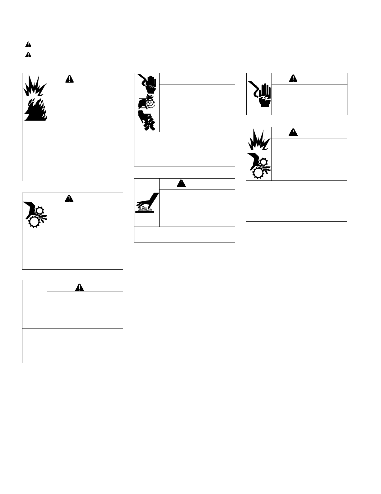
Maintenance
WARNING
Explosive Fuel can cause
fires and severe burns.
Do not fill fuel tank while
engine is hot or running.
Gasoline is extremely flammable
and its vapors can explode if
ignited. Store gasoline only in
approved containers, in well
ventilated, unoccupied buildings,
away from sparks or flames.
Spilled fuel could ignite if it comes
in contact with hot parts or sparks
from ignition. Never use gasoline
WARNING
Accidental Starts can
cause severe injury or
death.
Disconnect and ground
spark plug lead(s) before
servicing.
Before working on engine or
equipment, disable engine as
follows: 1) Disconnect spark plug
lead(s). 2) Disconnect negative (–)
battery cable from battery.
CAUTION
Damaging Crankshaft
and Flywheel can cause
personal injury.
Using improper procedures can
lead to broken fragments. Broken
fragments could be thrown from
engine. Always observe and use
precautions and procedures when
installing flywheel.
WARNING
Hot Parts can cause
severe burns.
Do not touch engine
while operating or just
after stopping.
Never operate engine with heat
shields or guards removed.
WARNING
Rotating Parts can cause
severe injury.
Stay away while engine
is in operation.
Keep hands, feet, hair, and
clothing away from all moving
parts to prevent injury. Never
operate engine with covers,
shrouds, or guards removed.
WARNING
Carbon Monoxide can
cause severe nausea,
fainting or death.
Avoid inhaling exhaust
fumes.
Engine exhaust gases contain
poisonous carbon monoxide.
Carbon monoxide is odorless,
colorless, and can cause death if
inhaled.
SAFETY PRECAUTIONS
WARNING: A hazard that could result in death, serious injury, or substantial property damage.
CAUTION: A hazard that could result in minor personal injury or property damage.
NOTE: is used to notify people of important installation, operation, or maintenance information.
CAUTION
Electrical Shock can
cause injury.
Do not touch wires while
engine is running.
Page 5
Maintenance
WARNING
Before working on engine or equipment, disable engine as
follows: 1) Disconnect spark plug lead(s). 2) Disconnect
negative (–) battery cable from battery.
Accidental Starts can cause severe injury or
death.
Disconnect and ground spark plug lead(s)
before servicing.
Engine
Model
& Serial
Number
1. Only use genuine Exmark parts and lubrication products.
2. Always install new gaskets, O-rings and seals when assembling engine.
3. Always torque fasteners to specification and in sequence.
4. Always lubricate friction components with clean engine oil or engine assembly lube
when assembling engine.
MAINTENANCE INSTRUCTIONS
Normal maintenance, replacement or repair of emission control devices and systems may be performed by any repair
establishment or individual; however, warranty repairs must be performed by an authorized Exmark dealer.
Service Rules
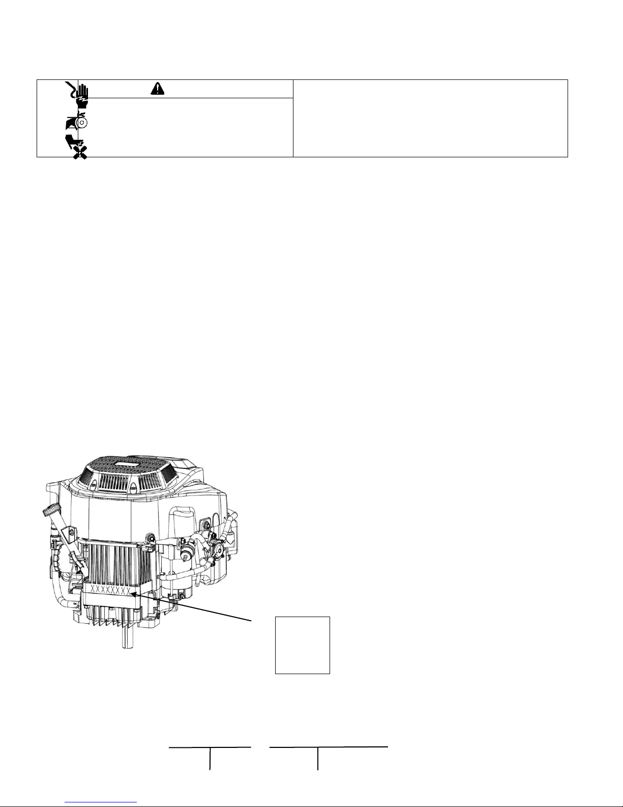
Engine Model / Serial Number Location
The engine model and serial number are stamped into the block, there will also be a label attached to
a new engine with this information on it as well.
XXX-XXXX XXXXXXXXXXX
Page 6
Maintenance
No.
Process Description
Bolt Specification
Torque Range
1
Oil Drain Plug Assy.
Oil Drain Plug
20 Ft. Lbs.
26 N.m
2
Spark Plug
M14×1
21 Ft. Lbs.
28 N.m
3
Connecting Rod Cover
Hex Flange Bolt M6×35
9 Ft. Lbs.
12 N.m
4
Crankcase Cover Bolt
Hex Flange Bolt M8×55
21 Ft. Lbs.
28 N.m
5
Fuel Pump Assy.
Hex Flange Bolt M6×16
5 Ft. Lbs.
7 N.m
6
Breather Valve Assy.
Hex Flange Bolt M6×12
8 Ft. Lbs.
10 N.m
7
Cylinder Head
Hex Flange Bolt M10×1.25×70
38 Ft. Lbs.
52 N.m
Hex Flange Bolt M10×1.25×50
8
Push Rod Location Limit Plate
Valve Adjust Stud
22 Ft. Lbs.
30 N.m
9
Valve Lash Inspection(Q1)
Valve Lock Nut M6
10 Ft. Lbs.
14 N.m
10
Valve Cover
Hex Flange Bolt M6×25
8 Ft. Lbs.
10 N.m
11
Flywheel
Hex Flange Bolt M12×35
62 Ft. lbs.
82 N.m
12
Ignition Coil
Hex Flange Bolt M6×20
8 Ft. Lbs.
10 N.m
13
Electric Starter Motor
Hex Flange Bolt M8×80
20 Ft. Lbs.
26 N.m
14
Inlet Pipe
Hex Flange Bolt M6×35
8 Ft. lbs.
10 N.m
Stud Bolt M6×106
5 Ft. Lbs.
7 N.m
15
Air Box
Nut, Flange M6
6 Ft. Lbs.
8 N.m
16
Cooling Fan
Hex Flange Nut M8×20
15 Ft. Lbs.
22 N.m
17
Cooling Fan Cover
Hex Flange Nut M5×16
3 Ft. lbs.
4 N.m
18
Fan Shroud
Hex Flange Step Bolt 6×21.8-8×10.8
6 Ft. Lbs.
8 N.m
19
Shroud Comp
Hex Flange Step Bolt 6×16.8-8×5.8
8 Ft. Lbs.
10 N.m
20
Starter Shroud
Screw ST4.0×15
10 – 11 In. Lbs.
1 N.m
21
Charging Coil
Screw Inner Six Angle M6×25
8 Ft. Lbs.
10 N.m
22
Engine Shroud
Hex Flange Bolt M6×16
8 Ft. Lbs.
10 N.m
23
Breather Valve Cover
Hex Flange Bolt M6×16
8 Ft. lbs.
10 N.m
24
Ignition Coil
Hex Flange Bolt M6×20
8 Ft. Lbs.
10 N.m
25
Regulator
Hex Flange Bolt M6×16
5 Ft. Lbs.
7 N.m
26
Oil Drain Fitting
/
20 Ft. lbs.
26 N.m
27
Oil Pump Cover
Hex Flange Bolt M6×16
8 Ft. Lbs.
10 N.m
28
Oil Screen Cover
Hex Flange Bolt M6×16
8 Ft. Lbs.
10 N.m
29
Oil Tube Plate
Hex Flange Bolt M6×16
8 Ft. lbs.
10 N.m
30
Governor Throttle
Hex Flange Bolt M6×16
8 Ft. Lbs.
10 N.m
31
Governor Arm
Nut M6
8 Ft. Lbs.
10 N.m
32
Tube Clip
Hex Flange Bolt M6×16
5 Ft. Lbs.
7 N.m
33
Connector, Oil Filter
M20
30 Ft. Lbs.
42 N.m
Engine Model
Serial Number
1.1 Torque values
Note: For unspecified bolts and nuts listed, refer to the table of standard torque values.
Page 7
Maintenance
34
Cylinder Head
Stud Bolt M8×39
11 Ft. Lbs.
14 N.m
Nut M8
13 Ft. Lbs.
17 N.m
35
Oil Filter
/
9 Ft. Lbs.
12 N.m
Part
Item
Standard
Service Limit
P/N 127-9041
P/N 127-9041
Engine
Ile speed
1800 RPM’s
+ or – 100 RPM’s
Operating RPM
3600 RPM’s
+ or – 50 RPM’s
Cylinder head
Warpage
0.0020” (0.05 mm)
Cylinder
Sleeve Taper / Out of Round
3.0315”-3.0319” (77 – 77.01 mm)
3.0354” (77.1 mm)
(Inside Diameter)
Piston
Skirt outside diameter
3.0301-3.0305” (76.965-76.975 mm)
3.0219” (76.755 mm)
Clearance to cylinder
0.00098-0.0017” (0.025-0.045 mm)
0.01000” (.255 mm)
Piston pin bore inside diameter
0.66937- 0.66961” (17.002-17.008 mm)
0.67402” (17.12 mm)
Piston – pin clearance
0..00016-0.00063” (0.004-0.016 mm)
0.0014” (0.029 mm)
Piston pin
Outside diameter
0.6689-0.6692” (16.992-16.998 mm)
0.6654” (16.9 mm)
Piston ring
Ring to Groove (Top and Middle
0.0008-0.0024” (0.02-0.06 mm)
0.0043” (0.11 mm)
End gap (top and middle )
0.0079-0.01578” (0.20-0.40 mm)
0.0177” (0.45 mm)
Width (top)
0.0382-0.0390” (0.97-0.99 mm)
0.0354” (0.9 mm)
Width (second)
0.0460-0.0469” (1.17-1.19 mm)
0.0433” (1.1 mm)
Width (oil ring)
0.0650-0.0728” (1.65-1.85 mm)
0.0630” (1.6 mm)
Connecting rod
Small end inside diameter
0.6695-0.670” (17.006-17.017 mm)
0.6712” (17.05 mm)
Big end inside diameter
1.575-1.576” (40.015-40.025 mm)
1.577” (40.065 mm)
Big end side clearance
0.0010-0.0031” (0.024-0.079 mm)
0.0051” (0.129 mm)
Crankshaft
Connecting Rod Journal Diameter
1.5735-1.5744” (39.966-39.991 mm)
1.555” (39.5 mm)
Valve
Clearance(cold) (intake)
0.004-0.006” (0.10-0.15 mm)
-
Clearance(cold) (exhaust)
0.006-0.008” (0.15-0.20 mm)
-
Stem diameter (intake)
0.258-0.259” (6.565-6.58 mm)
0.256” (6.515 mm)
Stem diameter (exhaust)
0.257-0.258” (6.545-6.56 mm)
0.258” (6.495 mm)
Valve guide
Inside diameter (intake, exhaust)
0.259-0.260” (6.6-6.615 mm)
0.262” (6.665 mm)
Stem to guide clearance (intake)
0.0008-0.0020” (0.02-0.05 mm)
0.006” (0.15 mm)
Stem to guide clearance exhaust)
0.0016-0.0027” (0.04-0.07 mm)
0.007” (0.17 mm)
Valve seat
Seat width
0.0027-0.0031” (0.7-0.8 mm)
0.051” (1.3 mm)
Valve spring
Free length
1.55-1.60” (39.5-40.5 mm)
1.535” (39 mm)
Cam shaft
Height (intake)
1.15-1.18” (29.95-30.05 mm)
1.17” (29.75 mm)
Height (exhaust)
1.15-1.18” (29.95-30.05 mm)
1.17” (29.75 mm)
Outside diameter (bearing)
0.628-0.629” (15.966-15.984 mm)
0.626” (15.916 mm)
1.2 Engine Specifications
Page 8
Maintenance
Crankcase cover
Camshaft hole diameter
0.629-0.630” (16-16.018 mm)
0.633” (16.068 mm)
Crankshaft hole diameter
1.575-1.576” (40.009-40.025 mm)
1.578” 40.075 mm)
Spark plug
Gap
0.0027-0.0031” (0.7-0.8 mm)
-
Ignition coils
Resistance (primary)
(1.6-1.9Ω)
-
Resistance (secondary)
(6.27.1kΩ)
-
Gap to flywheel
0.015-0.016” (0.4±0.1 mm)
-
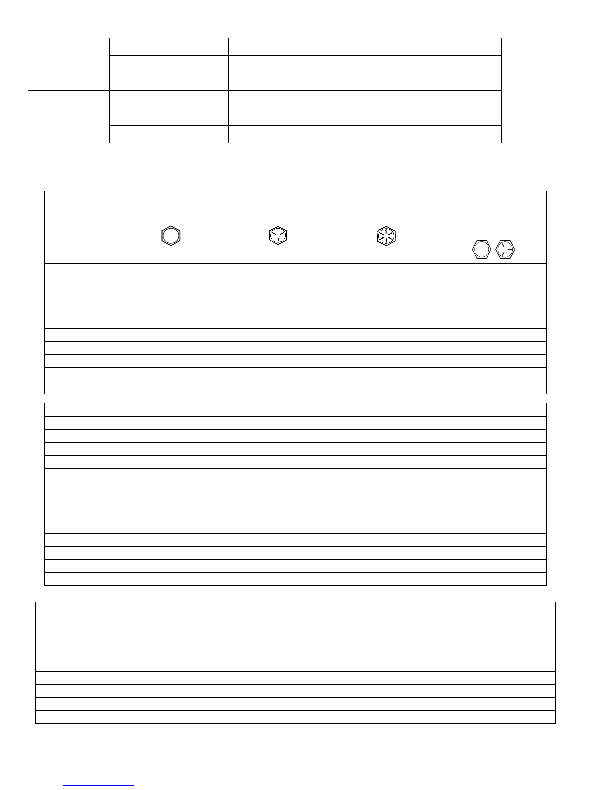
English Fastener Torque Recommendations for Standard Applications
Bolts, Screws, Nuts and Fasteners Assembled Into Cast Iron or Steel
Size Grade 2 Grade 5 Grade 8
Grade 2 or 5 Fasteners
Into Aluminum
Tightening Torque: N·m (in. lb.) ± 20%
8-32 2.3 (20) 2.8 (25) —
2.3 (20)
10-24 3.6 (32) 4.5 (40) —
3.6 (32)
10-32 3.6 (32) 4.5 (40) —
—
1/4-20 7.9 (70) 13.0 (115) 18.7 (165)
7.9 (70)
1/4-28 9.6 (85) 15.8 (140) 22.6 (200)
—
5/16-18 17.0 (150) 28.3 (250) 39.6 (350)
17.0 (150)
5/16-24 18.7 (165) 30.5 (270) —
—
3/8-16 29.4 (260) — —
—
3/8-24 33.9 (300) — —
—
Tightening Torque: N·m (ft. lb.) ± 20%
5/16-24 — — 40.7 (30)
—
3/8-16 — 47.5 (35) 67.8 (50)
—
3/8-24 — 54.2 (40) 81.4 (60)
—
7/16-14 47.5 (35) 74.6 (55) 108.5 (80)
—
7/16-20 61.0 (45) 101.7 (75) 142.5 (105)
—
1/2-13 67.8 (50) 108.5 (80) 155.9 (115)
—
1/2-20 94.9 (70) 142.4 (105) 223.7 (165)
—
9/16-12 101.7 (75) 169.5 (125) 237.3 (175)
—
9/16-18 135.6 (100) 223.7 (165) 311.9 (230)
—
5/8-11 149.5 (110) 244.1 (180) 352.6 (260)
—
5/8-18 189.8 (140) 311.9 (230) 447.5 (330)
—
3/4-10 199.3 (147) 332.2 (245) 474.6 (350)
—
3/4-16 271.2 (200) 440.7 (325) 637.3 (470)
—
Metric Fastener Torque Recommendations for Standard Applications
Property Class
Size
4.8 5.8
8.8 10.9 12.9
Noncritical
Fasteners
Into Aluminum
Tightening Torque: N·m (in. lb.) ± 10%
M4 1.2 (11) 1.7 (15) 2.9 (26) 4.1 (36) 5.0 (44)
2.0 (18)
M5 2.5 (22) 3.2 (28) 5.8 (51) 8.1 (72) 9.7 (86)
4.0 (35)
M6 4.3 (38) 5.7 (50) 9.9 (88) 14.0 (124) 16.5 (146)
6.8 (60)
M8 10.5 (93) 13.6 (120) 24.4 (216) 33.9 (300) 40.7 (360)
17.0 (150)
GENERAL TORQUE VALUES
Page 9

Maintenance
Tightening Torque: N·m (ft. lb.) ± 10%
M10 21.7 (16) 27.1 (20) 47.5 (35) 66.4 (49) 81.4 (60)
33.9 (25)
M12 36.6 (27) 47.5 (35) 82.7 (61) 116.6 (86) 139.7 (103)
61.0 (45)
M14 58.3 (43) 76.4 (56) 131.5 (97) 184.4 (136) 219.7 (162)
94.9 (70)
Torque Conversions
N·m = in. lb. x 0.113 in. lb. = N·m x 8.85
N·m = ft. lb. x 1.356 ft. lb. = N·m x 0.737
Page 10

Maintenance
2-1
2. Specifications
2.1 Specifications--------------------------------------------------2—2
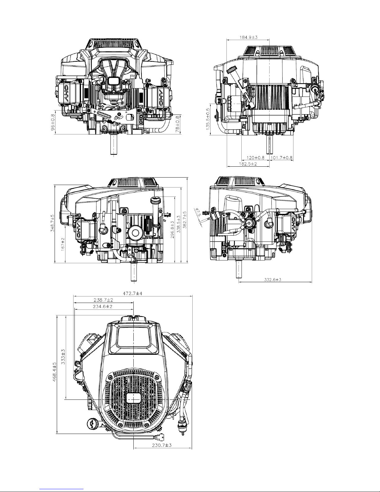
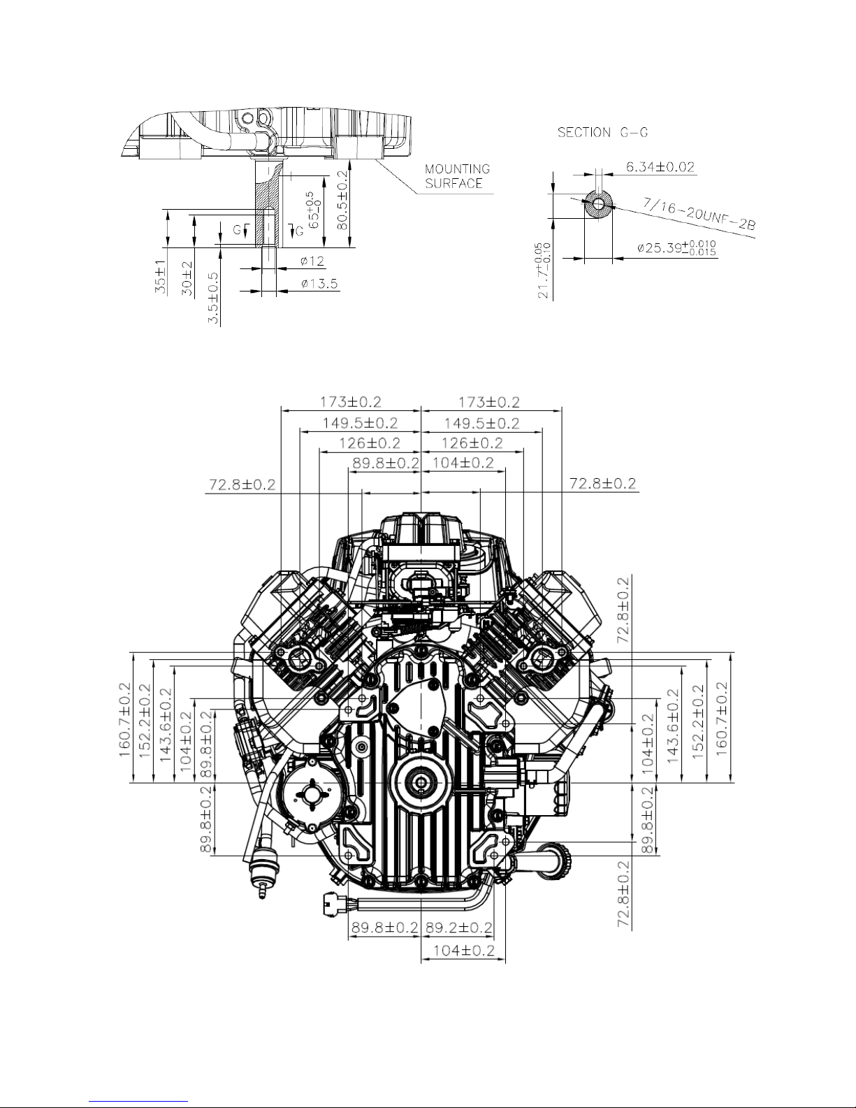
2.2 Dimensional drawings----------------------------------------2—2
2.1 Specifications
2.2 Dimensional Drawings in Millimeters
Model
P/N 127-9041 - 708 CC
Type
OHV, V-twin –Air Cooled 4-Stroke
Idle speed
1800 ± 50 rpm
Bore X Stroke
3.03” x 2.99” (77×76mm)
Displacement(cc)
43.20 Cubic Inches (708 cc)
Compression Ratio
8.7 :1
Lubricating mode
Full pressure
Starting mode
Electric
Rotation
Counter Clockwise(from P.T.O. side)
Valve clearance
Intake valve:0.004” - 0.006” , Exhaust valve:0.006” – 0.008”
Spark plug clearance
0.0027” - 0.0031” (0.7~0.8mm)
Igniting mode
Transistorized Magneto Ignition
Air cleaner
Foam & paper
Fuel type
Unleaded gasoline, minimum 87 Octane
Oil capacity
2.1 Quarts (2.0 liters)
Dimension(L×W×H)
18.44” x 18.61” x 15.06” (468.4×472.7×382.7 mm)
Net weight
89.95 lbs. (40.8 kg)
2
Page 11
Maintenance
2-2
Page 12
Maintenance
2-3
Page 13

Maintenance
2-4
Page 14

Maintenance
3-1
3 Maintenance
3.1 Maintenance schedule-----------------------------------------3-2
3.2 Engine oil ------------------------------------------------------ 3-2
3.3 Air cleaner ------------------------------------------------------3-3
3.4 Spark plug ------------------------------------------------------3-4
3.5 Valve clearance ------------------------------------------------3-4
3.6 Carburetor ----------------------------------------------------- 3-5
3.7 Governor -----------------------------------------------------3-5
3
Page 15
Maintenance
3-2
3.1 Maintenance Schedule
(1)Service more frequently when used in dusty condition areas.
(2)These items are to be maintained by designated dealers unless the user has special tools
and skills for maintenance.
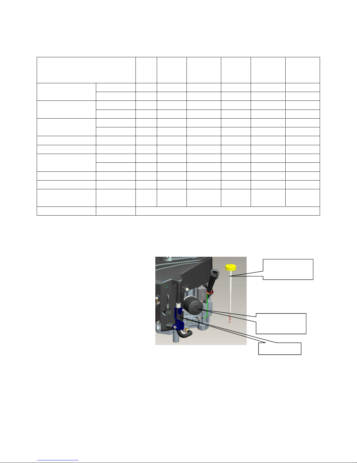
3.2 Engine Oil
Drain the oil while the engine is warm to
assure rapid and complete draining.
1. Clean the area around the oil filler
cap/dipstick. Remove
the oil filler cap/dipstick.
2. Drain the engine oil into a suitable
container using one of the following
methods.
Oil Drain:
a. Unwind the tube from the cleat
b. Pull hose down from the fitting
c. Allow the oil to drain into a suitable container.
d. Replace hose fully
Maintenance schedule
Each
Use
First 1
month
or 5 hours
Every 3
months or
25 hours
Every 6
months or
50 hours
Every year
or 100
hours
Every 2
years or
200 hours
Engine oil
Oil level ●
Change
● ●
Air cleaner foam
element
Clean
●(1)
Change
●(1)
Air cleaner paper
element
Clean
●(1)
Change
●(1)
Oil Filter
Change
●
Fuel filter
Replace
Spark plug
Replace
●
Check-adjust
●(2)
Valve clearance
Check-adjust
●(2)
Combustion chamber
Clean
●(2)
Remove engine
shroud and clean
Compressed
Air
●
Fuel hose
Every 3 years (Replace sooner if necessary) (2)
OIL FILLER
CAP/DIPSTICK
DRAIN LINE
OIL FILTER
Page 16

Maintenance
3-3
Engine Oil Capacity: 2.1 quarts (2.0 L)
Use a high-detergent, premium quality 4-stroke engine oil certified to meet or exceed US.
Automobile manufacturers’ requirements for API Service Classification SG, SF.
SAE 15W-40 is recommended for general, all-temperature use. Other viscosities shown in the chart may be
used when the average temperature in your area is within the indicated range.
3. Insert the oil filler cap/dipstick into the
oil filler tube. Remove the oil filler cap/dipstick
and check the oil level. Bring the level
to the upper mark on the dipstick.
after running the engine, recheck the oil
level and adjust if necessary.
Wash your hands thoroughly with soap
and water as soon as possible after
contact with used oil which contains
Carcinogenic substances.
Please dispose of used motor oil and the oil
containers in a manner that is compatible with the environment. We suggest you take it in a sealed container to
your local recycling center or service station for reclamation. Do not throw it in the trash, or pour it on the
ground.
UPPER LIMIT
LOWER LIMIT
Page 17

Maintenance
3-4
3.3 Air Cleaner
1. Lift open door
2. Rotate filter out from rear.
3. Clean the foam element by squeezing it in warm soapy water, rinsing it, and allowing it to dry. You may also
use a nonflammable solvent and then allow it to dry.
4. Clean the paper element by tapping it on a hard surface to knock off dirt, never used compressed air. Never
try to brush off the dirt. Brushing will force dirt into the filter fibers.
5. Use a damp rag to wipe any dirt from the inside of the air cleaner base and cover. Be careful not to allow dirt
into the duct leading to the carburetor.
6. Install filter in reverse order of removal
7. Close door
CAUTION: Operating the engine without an air filter, or with a damaged air filter, will
allow dirt to enter the engine, causing rapid engine wear. This type of damage is not covered by
the Distributor’s Limited Warranty.
3.4 Spark Plug
CLEANER
COVER
ELEMENT
AIR CLEANER BASE
Page 18

Maintenance
3-5
Recommended types: BOSCH F7RTC NHSP BP7RES CHAMPION RN9YC
NOTICE
Spark plugs of the wrong size or incorrect heat range
can cause engine damage.
1. Disconnect the spark plug lead and remove any dirt
from around the spark plug area.
2. Remove the spark plug with a spark plug wrench.
3. Inspect the spark plug for excessively worn electrodes,
chips or cracks in the insulator, or excessive deposits.
Replace the spark plug if you have any doubts about
its condition.
4. Measure the electrode gap with a wire gap gauge. Adjust
the gap to 0.025 – 0.030” by carefully bending
the ground electrode.
5. Use a spark plug wrench to tighten the plug enough to compress the washer. For a used plug, tighten 1/8 to
1/4 of a turn after the spark plug seats. For a new plug, tighten 1/2 turn after the spark plug seats. 18 – 22 ft.
lbs.
NOTICE
A loose spark plug can become hot enough to damage the engine. Over tightening a spark
plug can damage the threads in the engine.
6. Install the spark plug lead on the plug.
3.5 Valve Clearance
Valve clearance inspection and adjustment must be done with the engine cold.
1. Remove the valve cover, and set the first cylinder
piston at top dead center of the compression
stroke (both valves will be fully closed).
2. Measure the clearance between the rocker
arm and the valve stem with a feeler gauge.
Intake: 0.040” to 0.060” (0.10~0.15 mm)
Exhaust: 0.060” to 0.075 (0.15~0.20 mm)
3. To adjust valve clearance, hold the rocker arm
pivot and loosen the pivot lock nut.
4. Turn the rocker arm pivot to obtain the
specified clearance.
5. Hold the rocker arm pivot and tighten the pivot
lock nut.
6. Recheck the clearance and readjust if necessary.
7. Install the cylinder head cover.
8. Repeat procedure for the other side.
0.025” – 0.030”
0.70~0.80 mm
Page 19

Maintenance
3-6
3.6 Carburetor
Idle speed
1. Start the engine and allow the engine to
warm to normal operating temperature.
2. With the engine idling, adjust the throttle
stop screw to obtain the recommended
engine idle speed.
Recommended idle speed: 1800 ± 50 rpm
3.7 Governor
1. Loosen the governor arm pinch bolt nut.
but do not remove it.
2. Move the governor arm anti clockwise to
fully open the throttle and hold it in this
position.
3. Rotate the governor arm shaft fully
clockwise and hold it there with a pair
of pliers. Tighten the governor arm
pinch bolt nut to 8 ft. lbs. (11N·m) to secure the
governor arm to the governor arm shaft.
4. Check to be sure the governor arm and
throttle valve move free
Stop screw
Page 20

Maintenance
4-1
4 Disassembly and Service
4.1 Air cleaner --------------------------------------------------4-2
4.2 Engine cover --------------------------------------------------4-3
4.3 Control lever -------------------------------------------------4-4
4.4 Air Intake -----------------------------------------------------4-5
4.5 Carburetor ----------------------------------------------------4-5
4.6 Ignition coil --------------------------------------------------4-6
4.7 Flywheel/breather--------------------------------------------4-7
4.8 Cylinder head & valves -------------------------------------4-8
4.9 Crankcase cover/ governor --------------------------------4-11
4.10 Crankshaft /piston / camshaft ---------------------------4-14
4
Page 21

Maintenance
4-2
4.1 Air Cleaner
Page 22

Maintenance
4-3
4.2 Engine Cover
Page 23

Maintenance
4-4
4.3 Control Lever
Removal / Installation
Page 24

Maintenance
4-5
4.4 Air Intake
Page 25

Maintenance
4-6
4.5 Carburetor
NOTICE
No.
Process Description
Bolt Specification
Torque Range
N.m
In.lb.
1
Solenoid Valve
M12
6~9
53.1~79.6
2
Fuel Cup
Screw M4
1.5~2.0
13.3~17.7
3
Fuel Plug
Flange Bolt M6
6~9
53.1~79.6
4
Pin,Float
Screw M3
1.8~3.0
15.9~26.5
5
Main Jet
1.2~1.7
10.6~15
Page 26

Maintenance
4-7
4.6 Ignition Coil
Igniting coil gap adjustment
When reinstalling ignition coils, adjust the air
gap to: (0.015” – 0.020”)
1) Lightly tighten the igniting coil mounting bolt.
2) Insert the feeler gauge or a piece of paper of the same
thickness between the flywheel and coil as shown.
3) Push the coil against the flywheel by hand and tighten
the two bolts.
NOTICE
a) Adjust both ends of the coil to the same gap.
b) Avoid the magnet portion of the flywheel
when adjusting.
c) Inspect your work
Ignition Coil:
<Primary coil>
Put the tester terminal and lead terminal to contact with iron core of coil, and measure the primary coil resistance.
Primary coil resistance
1.6-1.9 Ω
<Secondary coil>
Put the tester terminal and removed spark plug cap’s high tension
cord to contact with iron cord and measure the secondary coil resistance.
Secondary coil resistance
6.2-7.1 KΩ
Adjustment
Adjustment is required only when the ignition coil or the flywheel has been removed.
1. Loosen the ignition coil mounting bolts.
2. Insert the thickness gauge or a piece of paper of the proper thickness between the ignition coil and the
flywheel, both gaps should be adjusted simultaneously. Avoid the magnet when adjusting the air gap.
3. Push the ignition coil firmly toward the flywheel and tighten the mounting bolts.
Specified clearance
0.015” – 0.020” (0.4 mm +/- 0.1mm)
Page 27

Maintenance
4-8
4.7 Flywheel /Breather
Removal / installation
NOTICE:
Disassembly:
Do not hit the flywheel with a hammer. Remove with a commercially available puller.
Avoid the magnet section when attaching the puller.
Reassembly:
Make certain there are no metal objects stuck to the magnet.
Adjust the ignition coil air gap after reassembly.
Page 28

Maintenance
4-9
4.8 Cylinder Head & Valves
Removal / Installation:
Remove the following:
1. engine cover
2. carburetor
3. Shroud Comp
Cylinder Head-Right
Page 29

Maintenance
4-10
Cylinder Head-Left
NOTICE:
Removal /Installation
Loosen and tighten Bolt, Cylinder Head in a crisscross pattern in 2~3 steps;
Before installation, remove any carbon deposits from the combustion chamber and
inspect the valve seats;
Measure the cylinder compression after reassembly.
Page 30

Maintenance
4-11
Disassembly / Reassembly
Inspection
Cylinder Head-Right
Page 31

Maintenance
4-12
Cylinder Head-Left
Valve Spring Free Length
Measure the free length of the valve springs.
Standard
Service limit
1.55” – 1.60”
1.53”
Replace the spring if they shorter than the service limit.
Valve Seat Width
Remove carbon deposits from the combustion
chamber. Inspection the valve seats for pitting or
other damage. Measure the valve seat width.
Standard
Service limit
0.028” – 0.030”
0.040”
If the valve seat width is under the standard, or
over the service limit, recondition the valve seat
Page 32

Maintenance
4-13
Cylinder Head
1、Remove carbon deposits from the combustion
chamber. Clean off any gasket material from the
cylinder head surface.
2、Check the spark plug hole and valve areas for cracks.
3、Check the cylinder head for warpage with a straight
edge and a feeler gauge as shown.
Service limit
0.002”
Valve Stem OD
Inspect each valve for face irregularities, bending
or abnormal stem wear. Replace the valve if necessary.
Measure and record each valve stem OD.
Standard
Service limit
IN
0.258” – 0.259”
0.255”
EX
0.257” – 0.258”
0.255”
Replace the valves if their OD is smaller than the service limit.
Valve Guide ID
Ream the exhaust valve guide to remove any
carbon deposits before measuring.
Measure and record each valve guide ID.
Standard
Service limit
0.259” – 0.260”
0.262”
Stem –to- Guide Clearance
Subtract each valve stem OD from the corresponding
guide ID to obtain the guide-to-stem clearance.
Standard
Service limit
IN
0.0008” – 0.0019”
0.0050”
EX
0.0015” – 0.0027”
0.0067”
If the stem-to-guide clearance exceeds the service limit, determine if the
new guide with standard dimensions would bring the clearance within
tolerance. If so, replace the guide (or cylinder head ) as necessary and
ream to fit. If the stem-to-guide clearance exceeds the service limit with
new guides, replace the valves as well.
Recondition the valve seat whenever the valve guide is replaced.
STRAIGHT EDGE
FEELER GAUGE
Page 33

Maintenance
4-14
Exhaust Valve Guide Reaming
For best results, be sure the cylinder head is at
room temperature before reaming the exhaust valve guide.
1. Coat the reamer and valve guide with cutting oil.
2. Rotate the reamer clockwise through the valve
guide the full length of the reamer.
3. Continue to rotate the reamer clockwise while
removing it from the valve guide.
4. Thoroughly clean the cylinder head to remove
any cutting residue.
5. Check the valve guide bore; it should be straight,
round and centered in the valve guide. Insert the valve
and check operation. If the valve does not operate
smoothly, the guide may have been bent during
installation. Replace the valve guide if it is bent or
damaged.
6. Check the valve stem-to-guide clearance
Valve Seat Reconditioning
1. Thoroughly clean the combustion chambers
and valve seats to remove carbon deposits.
2. Apply a light coat of Prussian Blue or erasable
felt-tipped marker ink to the valve faces.
3. Insert the valve, and then lift them and snap
them closed against their seats several times. Be
sure the valve does not rotate on the seat. The
transferred marking compound will show any
area of the seat that is not concentric.
4. Using a 45°cutter, remove enough material to
produce a smooth and concentric seat. Follow the
valve seat cutter manufacture’s instructions.
Turn the cutter clockwise, never counterclockwise.
Continue to turn the cutter as you lift it from the
valve seat.
5. Using the 30°~32° and 60° cutter to narrow
and adjust the valve seat so that it contacts the
middle of the valve face. The 30°~32° cutter removes
material from the top edge. The 60° cutter removes
material from the bottom edge. Bu sure that the width
of the finished valve seat is within specification.
CONTACT TOO LOW
CONTACT TOO HIGH
VALVE GUIDE
REAMER 0.259”
Page 34

Maintenance
4-15
Valve Seat Width
Standard
Service limit
0.0275” – 0.0315”
0.050”
1. Make a light pass with the 45° cutter to remove
any possible burrs at the edges of the seat.
2. After resurfacing the seats, inspection for even
valve seating.
3. Apply a light coat of Prussian Blue or erasable
felt-tipped marker ink to the valve faces.
4. Insert the valves, and then lift them and snap
them closed against their seats several times. Be
sure the valve does not rotate on the seat. The
seating surfacing, as shown by the transferred
marking compound, should have good contact all
the way around.
NOTICE
To avoid severe engine damage, be sure to
remove all lapping compound from the head
before reassembling.
5. Check the valve clearance after reassembly.
HAND VALVE LAPPER
Page 35

Maintenance
4-16
4.9 Crankcase Cover / Governor
Disassembly / Reassembly
Governor
NOTICE:
Check that the governor moves smoothly.
Page 36

Maintenance
4-17
Crankcase cover
Page 37

Maintenance
4-18
4.10 Crankshaft / Piston / Camshaft
Remove /installation
Page 38

Maintenance
4-19
Disassembly / Reassembly
Piston connecting rod
Assembly:
. Put the piston ring sign facing up when assembling.
. Don’t wrongly assemble the top ring and the second
ring.
. After assembling, be sure the piston can freely
move.
. Stagger the open of the piston to piston pin hole
with 120 degree.
Top ring
The second ring
Oil ring
Piston
Sign
Top ring
The second ring
Oil ring
Check, refer to
Piston pin
Piston ring clip
Assembly: Put the one end into the
piston slot, clamp other end by
sharp nose pliers and revolve into
slot. Don’t let the open of clip
aiming at the piston pin slot..
Connecting rod
Assembly: Put the long end of the
connecting rod aiming at the triangular
mark when assembling.
CLIP
CUT-OUT
Page 39

Maintenance
4-20
Piston Pin OD
Model
Standard
Service limit
LC2P77F
0.6689” – 0.6692”
0.6653”
Page 40

Maintenance
4-21
Cylinder Inside Diameter
Measure three points on the “X” and “Y” shaft
and record cylinder inside diameter(“X” shaft is vertical
to crankshaft and “Y” shaft parallel to crankshaft).
Take maximum reading as the wearing and tapering of
the cylinder.
Model
Standard
Service limit
708 CC
X: 3.0315”-3.0318”
Y: 3.0315”-3.0318”
3.0354”
3.0354”
Piston Skirt Outside Diameter
Measure and record the piston skirt outside diameter
at the 10mm from piston skirt maximum lower side
making 90°to piston pin hole.
Model
Standard
Service limit
708 CC
3.0301”-3.0351”
3.0218”
Piston- to – Cylinder Clearance
Standard
Service limit
0.0009”-0.0017”
0.010”
Piston Ring Side Clearance
Standard
Service limit
Top/
Second
0.0007” – 0.0023”
0.0043”
Piston Ring Width
Standard
Service limit
Top
00382”-0.0390”
0.0354”
Second
0.0460”-0.0468”
0.0433”
Page 41

Maintenance
4-22
Piston Ring End Gap
Standard
Service limit
0.0078” – 0.0157”
0.0177”
Before measuring end gap, use the piston top to position
the ring so it will not be cocked in the cylinder bore.
Connecting Rod Small End ID
Model
Standard
Service limit
708 CC
0.6695” – 0.6699”
0.6712”
Connecting Rod Large End ID
Original size
Model
Standard
Service limit
708 CC
1.5754” – 1.5757”
1.5773”
Crankshaft Pin OD
Model
Standard
Service limit
708 CC
1.5734” – 1.5744”
1.5551”
Page 42

Maintenance
4-23
Connecting Rod Large End Axial Clearance
Standard
Service limit
0.0177” – 0.0374”
0.0413”
Connecting Rod Large End Oil Clearance(Radial)
1) Clean all oil from the crankshaft neck journal
and inside side.
2) Place a piece of plastic gauge on the crankshaft
neck journal, assemble connecting rod, and tighten
the bolts to specified torque.
Bolt torque:9 ft. lbs. (12.5 N·m)
ATTENTION
3) Remove the connecting rod and measure the plastic
gauge.
4) If the clearance exceeds the service limit, replace
the connecting rod and recheck the clearance.
After using new connecting rod, the clearance still
exceeds the service limit, lap the neck journal and
use a connecting rod lower than standard value.
Camshaft Cam Height
Standard
Service limit
IN
1.179” – 1.183”
Replace under
1.171”
EX
1.179” – 1.183”
Replace under
1.171”
Camshaft OD
Standard
Service limit
0.6285” – 0.6293”
0.6266”
Note the location of the decompression mechanism,
check to be sure it moves freely.
Standard
Service limit
0.0015” – 0.0024”
0.0032”
Do not rotate the crankshaft while the
tightening connecting rod bolt
12.5 N·m
Page 43

Maintenance
4-24
Chapter 5 – Electrical System Information
Ignition Coil Gap Adjustment 1
Ignition Coil Resistance Inspection 1
Spark Testing 2
Fuel Solenoid 2
Charging System Specifications 3
AC Output Test 3
DC Output Test 4
5
Page 44

Maintenance
4-25
Ignition Coil Gap Adjustment
High Voltage Ignition Systems can be Dangerous - Use Caution when Servicing Ignition Systems
4) Install the ignition coil and lightly tighten the ignition coil mounting bolts.
5) Rotate engine so ignition coil is aligned with the magnet portion of the flywheel.
6) Insert the feeler gauge between the flywheel and coil.
7) Adjust the ignition coil gap at both sides of the coil.
8) Sufficiently tighten the mounting bolts.
Ignition Coil Resistance Inspection
Primary Coil
Place Ohm meter leads between the harness connection
lead and the exposed metal coil leg.
Secondary Coil
Place Ohm meter leads between exposed metal coil leg
and the spark plug terminal connection.
Ignition Coil Gap
0.011- 0.019”
(.3-.5 mm)
A - Primary Coil Resistance
1.0-1.6 Ω
B Secondary Coil Resistance
8.9 k Ω – 12.1 k Ω
A
B
Page 45

Maintenance
4-26
Spark Testing
- Fuel is Extremely Flammable - Use Extreme Caution When Servicing the Fuel System
- High Voltage Ignition Systems can be Dangerous - Use Caution when Servicing Ignition Systems
1. Remove spark plug cap from the spark plug.
2. Remove the spark plug from the engine.
3. Connect the negative (-) electrode of the spark plug (threaded area) to ground (cylinder head cover).
4. Crank the engine and view the electrode gap. Spark should be present when engine is turning over.
5. Reinstall the spark plug and torque to specification - 22 ft-lbs (30 Nm).
6. Properly install the spark plug boot.
Fuel Solenoid
Fuel Solenoid Resistance
Place Ohm meter leads between the harness connections,
Fuel Solenoid Resistance
35 - 45Ω
4
35 - 45Ω
Page 46

Maintenance
4-27
Charging System Specifications
AC Output Test
1. Insert RED
test
lead into
VC
receptacle
in meter.
2.
Insert BLACK
test lead into COM receptacle.
3. Rotate selector to
V-
(AC
VOLTS)
position.
4. Attach RED test lead clip (1) to AC output terminal(5),
Fig.18.
5. Attach BLACK test lead clip (2) to engine ground.
6. With engine
running
at 3600 RPM output should be no less than 14 volts
AC.
7. NOTE: The battery MUST be in good condition to
perform
this test.
Charge Coil(s) Air Gap
Measure Between the Magnet Area of the Flywheel and the
Charge Coil Legs
0.011- 0.019” (.3-.5 mm)
No Load DC Voltage Output @ 3000 RPM
Measure Across Battery Terminals
14.5 +/- .5 Volts DC
No Load AC Voltage Output @ 3000 RPM
Measure Across Stator Leads – Stator Leads Disconnected
30 VAC
Charge Coil / Stator Resistance
Measure Resistance Across the Two Stator Leads
0.16 Ohms +/- 15%
Page 47

Maintenance
4-28
DC Output Test
1.
Insert RED test
lead into
1
OA
receptacle in
meter.
2. Insert BLACK test lead into COM receptacle
in
meter.
3. Rotate selector to A== (DC AMPS) position.
4. Attach RED test lead clip (1) to DC
output
pin (6)in connector (4),
Fig.16. If NO or LOW output is found,
replace stator.
 Loading...