

Exlar GSM20, GSM30, GSM40 Installation And Service Manual

Curtiss-Wright | GSM Series Rev. U PN29959 3/28/17
1
GSM Series Linear Actuator
Installation and Service Manual
Information furnished by Exlar Corporation is believed to be accurate and reliable.
However, no responsibility is assumed by Exlar Corporation for its use. Exlar reserves the
right to change the design and operation of the equipment described herein and any
associated motion products that may appear in this document. Information in this document
pertaining to equipment not furnished by Exlar should be confirmed by that equipment
manufacturer. Exlar assumes no responsibility for changes to information by other
manufacturers or errors in that information or the description of that information. Information
in this document is subject to change without notice.
This document does not contain any export controlled data.

Curtiss-Wright | GSM Series Rev. U PN29959 3/28/17
2
TABLE OF CONTENTS
1.0 Introduction ....................................................................................... 3
1.1 Warranty and Limitations of Liability ............................................. 3
1.2 Safety Considerations .................................................................. 4
2.0 System Configuration ....................................................................... 4
2.1 Typical System Configuration ....................................................... 4
2.2 Typical System Wiring .................................................................. 5
2.3 Feedback Information ................................................................... 5
2.4 Cable Routing ............................................................................... 7
2.5 Anti-Rotation Option ..................................................................... 7
2.6 External Limit Switch Option ......................................................... 8
2.7 Rear Brake Option ...................................................................... 10
2.8 Ingress Protection ....................................................................... 12
3.0 Installation and Operation .............................................................. 13
3.1 Lubrication Requirements ........................................................... 13
3.2 Mounting Configurations ............................................................. 13
3.3 Mounting Considerations ............................................................ 13
3.4 General Operation ...................................................................... 14
3.5 Manual Drive Operating Instructions .......................................... 15
4.0 Maintenance Procedures ................................................................ 16
4.1 Disassembly ............................................................................... 16
4.2 Lubrication Maintenance ............................................................ 17
4.3 Reassembly ................................................................................ 18
4.4 Seal Maintenance ....................................................................... 19
5.0 Class I Division 2 Option ................................................................ 21
5.1 Terminal Box Wiring Diagram ..................................................... 22
5.2 Class I Division 2 Terminal Box Terminations ............................ 22
5.3 Terminal Box Dimensions ........................................................... 24
6.0 Troubleshooting Procedures ......................................................... 25
6.1 Returning a Product for Repair ................................................... 26
7.0 Certifications ................................................................................... 28
Refer to www.exlar.com for connector and wiring information.

Curtiss-Wright | GSM Series Rev. U PN29959 3/28/17
3
1.0 INTRODUCTION
1.1 Warranty and Limitation of Liability
Products are warranted for two years from date of manufacture as determined by the serial
number on the product label. Labels are generated and applied to the product at the time of
shipment. The first and second digits are the year and the third and fourth digits represent the
manufacturing week. Product repairs are warranted for 90 days from the date of the repair. The
date of repair is recorded within Exlar’s database tracked by individual product serial number.
Exlar Corporation warrants its product(s) to the original purchaser and in the case of original
equipment manufacturers, to their original customer to be free from defects in material and
workmanship and to be made only in accordance with Exlar's standard published catalog
specifications for the product(s) as published at the time of purchase. Warranty or performance to
any other specifications is not covered by this warranty unless otherwise agreed to in writing by
Exlar and documented as part of any and all contracts, including but not limited to purchase
orders, sales orders, order confirmations, purchase contracts and purchase agreements. In no
event shall Exlar be liable or have any responsibility under such warranty if the product(s) has
been improperly stored, installed, used or maintained, or if Buyer has permitted any unauthorized
modifications, adjustments and/or repairs to such product(s). Seller's obligation hereunder is
limited solely to repairing or replacing (at its opinion), at the factory any product(s), or parts
thereof, which prove to Seller's satisfaction to be defective as a result of defective materials, or
workmanship and within the period of time, in accordance with the Seller's stated product
warranty (see Terms and Conditions above), provided, however, that written notice of claimed
defects shall have been given to Exlar within thirty (30) days from the date of any such defect is
first discovered. The product(s) claimed to be defective must be returned to Exlar, transportation
prepaid by Buyer, with written specification of the claimed defect. Evidence acceptable to Exlar
must be furnished that the claimed defects were not caused by misuse, abuse, or neglect by
anyone other than Exlar.
Components such as seals, wipers, bearings, brakes, bushings, gears, splines, and roller
screw parts are considered wear parts and must be inspected and serviced on a regular basis.
Any damage caused by failure to properly lubricate Exlar products and/or to replace wear parts at
appropriate times, is not covered by this warranty. Any damage due to excessive loading is not
covered by this warranty.
The use of products or components under load such that they reach the end of their expected
life is a normal characteristic of the application of mechanical products. Reaching the end of a
product’s expected life does not indicate any defect in material or workmanship and is not
covered by this warranty.
Costs for shipment of units returned to the factory for warranty repairs are the responsibility of
the owner of the product. Exlar will return ship all warranty repairs or replacements via UPS
Ground at no cost to the customer.
For international customers, Exlar will return ship warranty repairs or replacements via UPS
Expedited Service and cover the associated shipping costs. Any VAT or local country taxes are
the responsibility of the owner of the product.
The foregoing warranty is in lieu of all other warranties (except as Title), whether expressed or
implied, including without limitation, any warranty of merchantability, or of fitness for any particular
purpose, other than as expressly set forth and to the extent specified herein, and is in lieu of all
other obligations or liabilities on the part of Exlar.
Seller's maximum liability with respect to these terms and conditions and any resulting sale,
arising from any cause whatsoever, including without limitation, breach of contract or negligence,
shall not exceed the price specified herein of the product(s) giving rise to the claim, and in no
event shall Exlar be liable under this warranty otherwise for special, incidental or consequential
damages, whether similar or dissimilar, of any nature arising or resulting from the purchase,
installation, removal, repair, operation, use or breakdown of the product(s) or any other cause
whatsoever, including negligence.
The foregoing warranty shall also apply to products or parts which have been repaired or
replaced pursuant to such warranty, and within the period of time, in accordance with Seller's
stated warranty.
NO PERSON INCLUDING ANY AGENT OR REPRESENTATIVE OF EXLAR IS
AUTHORIZED TO MAKE ANY REPRESENTATION OR WARRANTY ON BEHALF OF EXLAR
CONCERNING ANY PRODUCTS MANUFACTURED BY EXLAR, EXCEPT TO REFER
PURCHASERS TO THIS WARRANTY.
Curtiss-Wright | GSM Series Rev. U PN29959 3/28/17
4
1.2 Safety Considerations
As with any electro-mechanical device, safety should be considered
during the installation and operation of your GSM Series actuator.
Throughout this manual you will see paragraphs marked with CAUTION
and WARNING signs as shown below.
Pay particular attention to these paragraphs. They are intended to
provide you with helpful information to ensure safe and trouble-free
installation.
2.0 SYSTEM CONFIGURATION
2.1 GSM Series Actuator System Configuration
GSM Series actuators incorporate an integral brushless servo motor.
The design of this motor and selection of the proper feedback
configuration allows GSM Series actuators to be powered by nearly
every brand of brushless motor amplifier on the market.
This flexibility allows GSM Series actuators to be incorporated into the
highest performance single and multi- axis motion control systems in use
today. In applications varying from food and beverage packaging to
multi-axis turning centers to aircraft assembly, the GSM Series of
actuators show incredible performance and durability.
The high torque to volume ratio available from a brushless motor,
combined with the robust, high speed and high load capability of the
planetary roller screw, make the Exlar line of linear actuators a true, all
electric replacement for cumbersome high maintenance hydraulics. The
use of electronic servo control provides simpler set up and more precise
control than hydraulic systems as well.
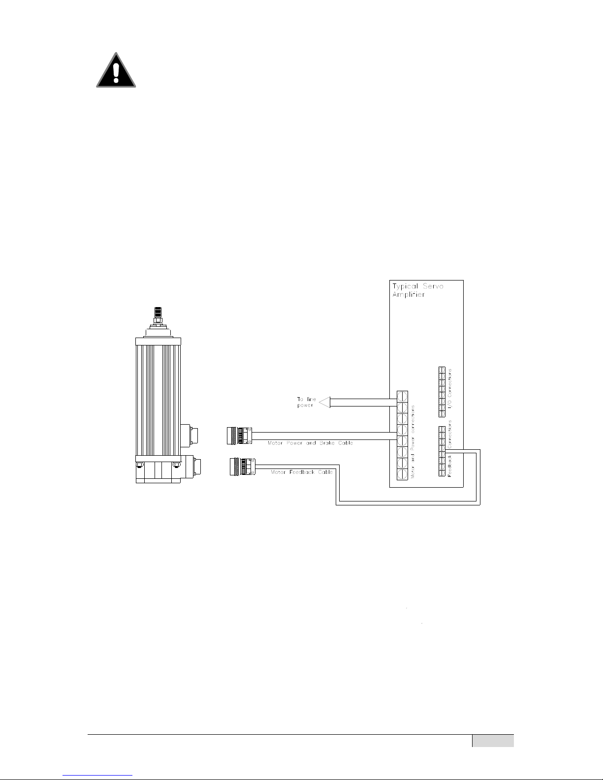
The schematic, next page, shows the typical connections for a single
axis system incorporating an Exlar GSM Series actuator and servo
amplifier. Each brand of brushless motor amplifiers may have unique
wiring requirements, parameter settings and operational principals that
affect how the actuator operates. The drawing on the following page
shows general connection principals for typical resolver and encoder
feedback amplifiers. Details on connections to specific brands of
amplifiers can be obtained from www.exlar.com.
CAUTION
WARNING
Curtiss-Wright | GSM Series Rev. U PN29959 3/28/17
5
WARNING: Attempting to connect the power cable to the
motor feedback connector may cause damage to the
connector. Verify that pin patterns match before attempting to
connect cables to actuator.
Never attempt to connect or disconnect the actuator with power
applied. Dangerous voltages are present. Damage to equipment and
injury to personnel can result. Many amplifiers have voltage present
for a considerable time period after incoming power is removed.
Take care to insure that the amplifier has discharged all power.
2.2 Typical System Wiring
Please refer to www.exlar.com for information on connectors and
wiring.
2.3 Feedback Information
GSM Series actuators incorporate a quadrature incremental encoder
with commutation signals as the primary rotary feedback device. The
alignment of this feedback device is dictated by the amplifier that the end
user chooses for operating the actuator. This amplifier is indicated in the
model number of the GSM Series actuator as a 3 digit code consisting of
2 letters and 1 number.
Typical System Connections

Curtiss-Wright | GSM Series Rev. U PN29959 3/28/17
6
Each amplifier has specific requirements for the feedback on the
motor. Not all encoder-based amplifiers can use the same encoder,
encoder alignment or relative direction of encoder rotation.
Many amplifiers offer software that allows the entering of parameters
or the downloading of motor data files that dictate how the feedback
must be set up on the motor. Exlar can provide many of these data files
or the proper parameters to enter. Entering motor parameter data to
some amplifiers may require assistance from the amplifier manufacturer.
Feedback Alignment
When Exlar manufactures a GSM Series actuator, the proper
feedback is selected, mounted, aligned and test run on the amplifier that
the customer plans to use, or one that is known to be equivalent for
confirming proper feedback alignment and operation. In any case where
it is determined that the feedback has become misaligned, or an
amplifier change is made requiring the feedback to be aligned differently,
it is recommended that Exlar be contacted and arrangements made to
have that procedure performed.
Feedback Wiring
The wiring of the feedback device is critical to the operation of the
actuator with the selected amplifier. Wiring the feedback cable
improperly can cause unstable operation, incorrect operation or no
operation at all. In some cases, if the proper current limits are not set in
the amplifier, improper wiring of the feedback cable can lead to damage
of the motor.
Encoders
An incremental encoder is an electronic rotary device that transmits a
string of electrical pulses when rotated. Most brushless motors or servo
systems that use incremental encoders use what is called a quadrature
encoder. Typical brushless motor encoders use two data channels,
labeled A&B, to provide direction, velocity and position information. The
Channel labeled I or Z has one pulse per revolution and is called the
index. The channels labeled as hall signals, or commutation signals, are
typically labeled S1, S2 & S3; Hall 1, 2 & 3, or Hall A, B & C, depending
on the manufacturer's conventions. These signals give the amplifier the
commutation information that it needs to properly rotate the motor.

Curtiss-Wright | GSM Series Rev. U PN29959 3/28/17
7
GSM Series Feedback Devices
Standard GSM Series actuators use encoders as their primary feedback
device. Depending on the amplifier that will be used to operate the
actuator, the hookup of the actuator can vary. Always consult Exlar for
the correct wiring details or visit www.exlar.com.
2.4 Cable Routing
Over time, liquid contaminants such as oil and cleaning solutions will
run down the cables and into any exposed connectors. To minimize the
introduction of contaminants to the connector, route the cables so that
there is a loop in the cable just prior to its attachment to the connector.
Two examples are shown below, depending on the orientation of the
connectors. Units mounted in such a way that the connectors are on the
bottom surface of the actuator require no looping.
2.5 GSM Series Linear Actuator Anti-rotation Option
The unique design of the GSM Series linear actuators allows the
extending rod to rotate. This simplifies the setup of the actuator by
allowing the user to rotate the rod and thread it in and out of the actuator
for mechanical attachment or system testing.
This feature also requires that the rod be kept from rotating when used
in its dedicated application to insure proper linear motion. In most
applications, such as those where the load is coupled to linear bearings
or some other support device, the load cannot rotate, providing antirotation for the extending rod of the actuator.
For applications in which the load is free to rotate, Exlar offers the antirotation systems shown below. The drawings on the next page show the
rod and bushing on only one side of the actuator. For long stroke
actuators, the rod and bushing are required on both sides of the actuator.
Top Mount Side Mount
Loop Loop

Curtiss-Wright | GSM Series Rev. U PN29959 3/28/17
8
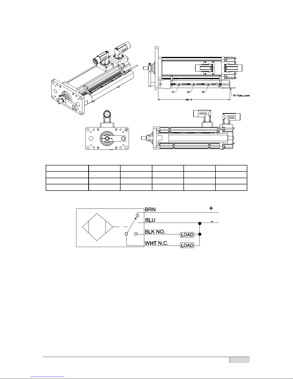
2.6 GSM Linear Actuator External Limit Switch
With the anti-rotate option (Section 2.6) the GSM actuator can
accommodate 1, 2 or 3 external limit switches for use as end of
travel limit switches or home position sensors in low profile
extruded channel housing. A bracket with inductive proximity
switches mounts to the tie rods and senses a traveling magnet
inside the extrusion.
Anti-Rotate Option Dimensions
Dimensions in
inches
GSM20
GSM30
GSM40
A
0.60
0.79
1.25
B
1.81
2.54
3.78
C
0.54
0.71
0.98
D
1.00
1.29
1.65
E
0.44
0.44
0.63
F
0.28
0.32
0.38
G
0.31
1.69
1.69
H
0.37
0.50
0.50
Curtiss-Wright | GSM Series Rev. U PN29959 3/28/17
9
External Limit Switch Dimensions
The number of switches desired is selected by ordering the L1, L2 or
L3 option, in which 1, 2, or 3 switches will be provided, respectively.
The switches are 9-30 VDC powered, PNP output, with either normally
open or normally closed logic operation depending on the switch
configuration ordered. Below is a diagram indicating which logic
operation will be provided for each switch, based on the option ordered.
DIM "A" 3" Stroke 6" Stroke 10" Stroke 12" Stroke 18" Stroke
GSM20 5.515 8.515 n/a 14.515 n/a
GSM30 6.932 9.832 13.832 15.832 21.832
GSM40 n/a 9.832 13.832 15.832 21.832

Curtiss-Wright | GSM Series Rev. U PN29959 3/28/17
10
Configuration of Logic of Standard Switch Option Selections
Option
SW1
SW2
SW3
L1
Not Supplied
Normally Open
Not Supplied
L2
Normally Closed
Not Supplied
Normally Closed
L3
Normally Closed
Normally Open
Normally Closed
Switch Type
Exlar Part
Number
Turck Part Number
Normally Closed Switch
43404
BIM-UNT-RP6X
Normally Open Switch
43403
BIM-UNT-AP6X
2.7 Internal Holding Brake
Many applications require the addition of the rear internal holding
brake. The brake is held open by the supply of power to a
magnetic/mechanical clutch. Whenever there is not power to the brake,
the armature is held in place to prevent the inverted roller screw from
turning and prevent the output rod from back driving, which therefore
prevents the output rod from moving.
The holding brake is permanent magnet engaged and electrically
released. The mechanical advantage of the roller screw allows the
holding brake to prevent back driving of the load. The holding capacity of
the brake is sufficient to hold the rated force of the actuator when used in
grease lubricated units.
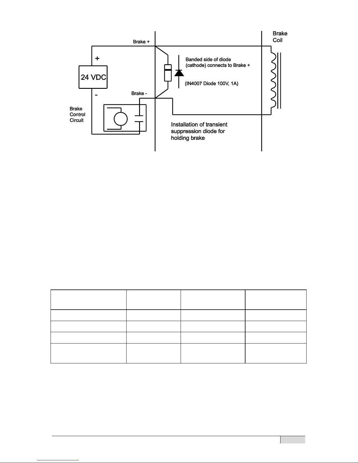
Historically, Exlar actuators and motors with holding brakes provided a
transient suppression diode wired internally to the actuator or motor.
With the changes in servo amplifier and control technology, there are
now instances where the diode is not required to be within the motor. An
example of this is a control system using a dedicated brake control relay
containing transient suppression components.
Because of this change in technology, Exlar now provides the
transient suppression diode separately from the actuator, for inclusion in
the brake control circuitry as needed by the end user. A schematic is
provided below showing the typical use of the transient suppression
diode.
Curtiss-Wright | GSM Series Rev. U PN29959 3/28/17
11
If the user is uncertain about the requirements for transient
suppression, they should refer to their servo amplifier or controller
technical documentation, or contact their servo amplifier or controller
manufacturer for technical support.
For connection of your amplifier and actuator (including rear brake
leads), refer to the wiring information at www.exlar.com/cablesconnections/.
The rear brake option adds length to the dimensions of the GSM
actuators as follows: (See drawings in Section 5.2.)
GSM20: Add 1.784 inches (45.3 mm) if ordering brake
GSM30: Add 1.6 inches (40.6mm) if ordering brake
GSM40: Add 2.33 inches (59.2 mm) if ordering brake
BRAKE
SPECIFICATIONS
GSM20
GSM30
GSM40
Holding torque
19 lb-in
70 lb-in
97 lb-in
Voltage
24 VDC
24 VDC
24 VDC
Current required
0.75 Amps
0.75 Amps
0.88 Amps
Coil resistance
(polarity sensitive)
70.6 Ohms
48 Ohms
36 Ohms
 Loading...