

Exinda EXNV-3062, EXNV-6062, EXNV-4062, EXNV-8063, EXNV-12063 Administration Manual
...
ADMINISTRATION GUIDE
Find out how to set up and configure Exinda Network Orchestrator in different
environments and how to customize advanced features.

The information and content in this document is provided for informational purposes only and is provided "as is" with no warranties of
any kind, either express or implied, including without limitation any warranties of merchantability, fitness for a particular purpose, and
non-infringement. GFI Software disclaims and in no event shall be liable for any losses or damages of any kind, including any
consequential or incidental damages in connection with the furnishing, performance or use of this document. The information is
obtained from publicly available sources. Though reasonable effort has been made to ensure the accuracy of the data provided, GFI
makes no warranty, promise or guarantee about the completeness, accuracy, recency or adequacy of information contained in this
document and is not responsible for misprints, out-of-date information, or errors. GFI reserves the right to revise or update its products,
software or documentation without notice. You must take full responsibility for your use and application of any GFI product or service. No
part of this documentation may be reproduced in any form by any means without prior written authorization of GFI Software.
If you believe there are any factual errors in this document, please contact us and we will review your concerns as soon as practical.
GFI and Exinda Network Orchestrator are trademarks or registered trademarks of GFI Software or its affiliates in the US and other countries.
Any other trademarks contained herein are the property of their respective owners.
Exinda Network Orchestrator is copyright of Exinda Inc.. - 1999-2017 Exinda Inc.. All rights reserved.
Document Version: 7.4.7
Last updated (month/day/year): 05/23/2018

Contents
1 Introduction 8
1.1 How an Exinda implements WAN optimization
1.2 What is network orchestration?
1.3 Exinda system components
1.3.1 Exinda Appliance
1.3.2 Exinda Web UI
1.3.3 Exinda Management Center
1.3.4 Exinda Solution Center
1.3.5 Exinda Service Delivery Point (SDP)
1.4 The Exinda product line
1.4.1 Exinda physical appliances
1.4.2 Exinda virtual appliances
1.5 Product naming conventions
2 Getting started 17
2.1 WUI Guided Tour
2.2 Deployment options
2.2.1 Key terms
2.2.2 Basic characteristics and behaviors of Exinda Appliances
2.2.3 In-path topologies
2.2.4 Out-of-path topologies
2.2.5 Clustering topologies
2.3 Upgrading and downgrading
2.3.1 Upgrading to the latest firmware version
2.3.2 Rolling back to the previously installed version of ExOS
2.4 Installing an Exinda Appliance
2.4.1 Gathering required information
2.4.2 Connecting the appliance to the physical network
2.4.3 Installing an Exinda Virtual Appliance
2.4.4 Scenario
2.4.5 Use Case
2.4.6 Scenario
2.4.7 Use-case
2.4.8 Use Cases
2.4.9 Related Topics
2.4.10 Related Topics
2.4.11 Related Topics
2.4.12 Related Topics
2.4.13 Related Topics
2.4.14 Related Topics
2.4.15 Related Topics
2.4.16 Related Topics
2.4.17 Related Topics
2.4.18 Related Topics
2.4.19 Related Topics
2.4.20 Related Topics
2.4.21 Related Topics
2.4.22 Creating an initial configuration using the Basic Wizard
2.4.23 Licensing information
8
8
8
8
9
9
9
9
9
9
15
16
17
18
18
18
19
28
57
61
61
62
63
64
64
65
75
75
77
77
78
92
92
102
108
109
116
121
122
124
126
126
134
135
135
139

2.5 Managing multiple appliances with the Exinda Management Center
2.5.1 Getting started with EMC
2.5.2 Deploying Exinda Management Center as a Virtual Machine
2.5.3 How EMC fits into the appliance feedback loop
2.5.4 Exinda Management Center Concepts
2.5.5 Best Practices
2.5.6 Configuring the EMC
2.5.7 Importing appliance configuration
2.5.8 Configuring an appliance manually
2.5.9 Configuring a bridge
2.5.10 Optimizer Policy Tree
2.5.11 Sending configuration changes to the appliances
144
145
145
147
147
147
149
153
158
161
164
170
3 Using 172
3.1 Defining a network environment
3.1.1 Adding network objects
3.1.2 Working with dynamically created network objects
3.1.3 Working with users and groups as objects
3.1.4 Configuring VLAN objects
3.1.5 Adding protocol objects
3.1.6 Adding application objects
3.1.7 Adding and updating application group objects
3.1.8 Configuring anonymous proxy detection and monitoring
3.1.9 Configuring service level agreement objects
3.1.10 Creating an HTML response object
3.1.11 Configuring schedule objects
3.1.12 Configuring adaptive response limits
3.1.13 Configuring application performance score objects
3.1.14 Configuring an application performance metric object
3.2 Monitoring your network
3.2.1 Dashboards
3.2.2 Monitoring network traffic in real time
3.2.3 Monitoring network interfaces
3.2.4 Monitoring network throughput
3.2.5 Monitoring service levels
3.2.6 Monitoring applications
3.2.7 Monitoring network users
3.2.8 Monitoring hosts traffic volume
3.2.9 Monitoring network conversations
3.2.10 Monitoring subnets
3.2.11 Monitoring virtual circuits
3.2.12 Monitoring the effects of controls
3.2.13 Monitoring optimization reports
3.2.14 Monitoring Exinda Appliance system performance
3.2.15 Viewing monitoring statistics
3.3 Monitoring applications with the Exinda Solution Center
3.3.1 How performance reports work
3.3.2 Using Application Performance reports
3.3.3 Bandwidth usage
3.3.4 Using the Application Performance Monitor VoIP report
3.3.5 Recreational Traffic
3.3.6 Data Center Continuity
3.3.7 RIAA Notice Prevention
172
172
182
184
186
190
190
193
199
201
206
208
210
216
229
231
232
237
249
252
254
265
275
278
281
284
289
292
299
304
313
322
323
324
326
327
329
329
330

3.3.8 Using Network Governance reports
3.3.9 Answers to common questions about Solution Center Application Performance
3.3.10 Adding and deleting Solutions
3.3.11 Setting a new baseline
3.3.12 Working with Application Performance charts
3.3.13 Investigating a poor application performance score (APS)
3.3.14 Investigating unusual performance
3.3.15 Deleting an Application Performance report
3.4 Managing network traffic
3.4.1 The Exinda policy tree
3.4.2 Circuits
3.4.3 Virtual Circuits
3.4.4 Policies overview
3.4.5 The optimizer wizard
3.4.6 Calculating network performance metrics
3.5 Configuring for common use cases and scenarios
3.5.1 Monitoring and controlling traffic in a captive portal system
3.5.2 Backhauling Internet traffic
3.5.3 Setting and enforcing quotas
3.5.4 Creating Applications from DSCP-marked traffic (like Riverbed accelerated traffic)
3.5.5 Clustering and high availability
3.5.6 Controlling anonymous proxy traffic
3.6 Managing Exinda Appliances with EMC
3.6.1 Viewing appliances in the tenancy
3.6.2 Moving appliances within the tenancy
3.6.3 Configuration Library
3.6.4 Configuring your Appliances through the CLI
3.7 Service Delivery Point (SDP)
3.7.1 SDP Web User Interface (WUI) and Features
3.7.2 Getting started with SDP
3.7.3 Changing the default view settings in SDP WUI
3.7.4 Tools
3.7.5 Managing appliances in SDP
3.7.6 The SDP dashboard
3.7.7 Viewing reports in SDP
3.7.8 Viewing the config log in SDP
3.7.9 Install SDP as a Virtual Appliance
332
333
334
335
335
336
336
336
337
338
341
348
362
380
384
389
389
394
396
400
401
408
409
410
410
413
450
451
452
453
461
465
467
473
474
476
477
4 Settings 481
4.1 Network settings
4.1.1 NIC configuration
4.1.2 IP address configuration
4.1.3 Routes configuration
4.1.4 DNS and domain names configuration
4.1.5 HTTP proxy configuration
4.1.6 Email configuration
4.1.7 SNMP configuration
4.1.8 Integrate with Active Directory
4.1.9 IPMI Configuration
4.1.10 Overview of QoS by host
4.2 System Setup
4.2.1 Date and Time Configuration
4.2.2 UI Access Configuration
481
481
484
487
488
491
491
494
499
519
523
547
547
550

4.2.3 SDP Configuration
4.2.4 Configure SQL Access
4.2.5 Monitoring Configuration
4.2.6 Netflow Configuration
4.2.7 Create a Scheduled Job
4.2.8 Alerts
4.2.9 Control Configuration
4.2.10 Disk Storage Explained
4.3 Certificates
4.3.1 Managing Certificates and CA Certificates
4.3.2 View all certificates and private keys
4.4 Optimization services
4.4.1 How Appliance Discovery Works
4.4.2 Configuring the Optimization Services
4.4.3 Universal Acceleration Service
4.4.4 Protocol-specific Acceleration
4.4.5 Data caching
4.5 Authentication
4.5.1 Display a List of Active Users
4.5.2 Local User Accounts
4.5.3 AAA
4.5.4 LDAP Authentication
4.5.5 Radius Authentication
4.5.6 TACACS+ authentication
4.6 System Maintenance
4.6.1 Manage System Configuration
4.6.2 Factory Defaults
4.6.3 Reboot/Shutdown
4.7 System Tools
4.7.1 Ping
4.7.2 Traceroute
4.7.3 DNS Lookup
4.7.4 Query a remote IPMI Exinda appliance
4.7.5 iPerf Client
4.7.6 iPerf Server
552
552
568
572
575
577
580
580
587
587
590
591
591
594
595
599
625
644
644
644
645
646
647
647
648
648
651
651
653
653
654
654
655
656
657
5 Troubleshooting 660
5.1 Diagnostics
5.1.1 Diagnostics Files
5.1.2 Acceleration Diagnostics
5.1.3 Monitor
5.1.4 NIC Diagnostics
5.1.5 Optimizer Diagnostics
5.1.6 RAID Diagnostics
5.1.7 TCP Dump
5.1.8 View the status of an alert
5.1.9 View the status of the community
5.1.10 Open a case with Exinda Networks Support Services
5.2 Log Files
5.2.1 Viewing System Log Files
5.2.2 Live Log
5.2.3 Tail Log
5.2.4 System Logging Configuration
660
660
661
664
665
666
667
668
670
671
672
672
673
673
673
674

5.3 Troubleshoot problems with MAPI acceleration
5.3.1 Outlook cannot connect to the Exchange server
5.3.2 Outlook slow to send or receive emails
5.3.3 Decrease in acceleration of MAPI traffic
5.3.4 Reduction ratio for MAPI is different between Client-side and Server-side Exindas
5.4 Troubleshoot issues with TCP acceleration
5.5 Troubleshoot issues with SMB file acceleration
5.6 Troubleshoot issues with Active Directory configuration
5.6.1 Exinda Appliance Reboots Every Night
5.6.2 WMI Service is not running
5.6.3 System account showing in traffic reports
5.6.4 No Communication Between the Exinda AD Connector and the Exinda Appliance
5.6.5 Exinda AD Connector stops running
5.6.6 Excluded Users Still Appear on the Exinda Appliance
5.6.7 Changes to the Exinda Active Directory Controller have no effect
5.6.8 The IP addresses are not being mapped to the AD users and groups
5.7 Troubleshooting Edge Cache
5.8 Topology troubleshooting
675
676
676
676
677
677
677
678
678
679
679
679
679
680
680
681
682
684
6 ExindaCommand Line Interface (CLI) 685
6.1 Using the Command Line Interface
6.1.1 Accessing the CommandLine Interface
6.1.2 CLI Configuration Jumpstart
6.1.3 Configure command line options
685
685
686
687
7 Copyright 689
7.1 Exinda End User License Agreement (EULA)
7.2 GNU General Public License (GPL)
7.2.1 Preamble
7.2.2 TERMS AND CONDITIONS
7.3 BSD 2.0
689
690
690
691
697
8 Safety and Compliance 699
8.1 EMC Notice
8.2 Compliances
8.2.1 CE
8.2.2 FCC Class A
8.3 Safety Guidelines
8.3.1 Lithium Battery Caution
699
699
699
699
700
700
9 Predefined Applications and Application Groups 701
9.1 Predefined Applications and Supported L7 Signatures
9.2 Predefined Application Groups
701
740

1 Introduction
Every day critical business network traffic and recreational network traffic compete for bandwidth on strained networks.
The Exinda Network Orchestrator inspects, monitors and manages network traffic, maximizing speed and data flow
efficiency, giving priority to mission critical business applications across your LANs and WANs.
1.1 How an Exinda implements WAN optimization
As soon as you connect it to your network, an Exinda Appliance begins monitoring network traffic and gathering
statistics to help you make informed optimization decisions. The Exinda provides a multitude of settings, parameters and
tools you can use to tweak and squeeze every last byte of bandwidth from your network hardware.
Traffic shaping techniques, classifying and rationing bandwidth in alignment with your company goals and daily
needs
Intelligent data caching for rapid access to frequently used files and data stores
Data deduplication to eliminate redundant data and free bandwidth
Network monitoring, analysis and management toidentify and limit social network traffic, gaming traffic, streaming
traffic and other non-essential traffic types
And getting started with Exinda Network Orchestrator is easy.
First you connect an Exinda Appliance to your network. Next, through the combination of an automatic, intelligent
discovery process and manual definitions, the Exinda Appliance learns about your network. Then you specify policies to
regulate traffic in your network. After that, you use Exinda's robust set of monitoring tools to gain total insight into the
traffic on your network and adjust your policies as needed.
1.2 What is network orchestration?
Network orchestration is the idea that networks can be programmed to support applications, giving priority to one over
another.
The Exinda Network Orchestrator provides the capability to detect and define data streams according to their origins,
destinations and other characteristics. Then it gives you the capability to set up rules governing how much network
resources a given data stream is allowed to consume.
An Exinda Network Orchestrator logically transforms your network from a group of disparate routers,hubs, switches,
bridges, repeaters and blade servers, working independently, into a single, responsive, service-based asset.
1.3 Exinda system components
Exinda includes a number of required and optional components that can be installed in your organization's
infrastructure.
1.3.1Exinda Appliance
The Exinda product line includes a series of hardware and virtual network appliances designed to plug directly into your
environment with minimal effort. Appliances come in a range of sizes to handle every networking scenario and size,
from small offices with dozens of users to very large data centers that support hundreds of thousands.
For more information, refer to The Exinda product line (page 9).
Exinda NetworkOrchestrator
1 Introduction |8

1.3.2Exinda Web UI
Exinda offers to user and administrator a Web User Interface that allows users to configure policies and monitor the
appliances performances through a variety of dashboard and reports.
1.3.3Exinda ManagementCenter
The Exinda Management Center (EMC) provides complete management insight and configuration control of your
Exinda Network Orchestrator appliances from one central console. All applications, devices, users, and activities across all
network locations are managed from a central location giving IT Administrators the ability to manage network policies
and manage appliance configuration across the entire organization.
For more information, refer to Managing multiple appliances with the Exinda Management Center (page 144).
1.3.4Exinda Solution Center
The Exinda Solution Center provides a series of predefined monitors you can run to generate network performances
reports for applications like FTP, SSH, Salesforce.com, Microsoft Office365, VoIP, and many more.
For more information, refer to Monitoring applications with the Exinda Solution Center (page 322).
1.3.5Exinda Service Delivery Point(SDP)
The Exinda Service Delivery Point (SDP) is a high performance add-on designed for enterprise network environments
looking to centrally manage multi-box Exinda deployments. It is available as both a hosted service and a virtual appliance.
SDP simplifies the tasks of installing, configuring, monitoring and reporting WAN optimization appliances. It is a key
differentiator in the traffic shaping & WAN optimization space. A fundamental component of Exinda's Unified
Performance Management solution, it rounds out the Exinda product line and makes it the most comprehensive and
effective solution for achieving peak application performance.
With secure access via a Web browser, SDP subscribers gain full visibility into network usage and control over applications
at any WAN site. SDP helps IT managers identify and control the underlying causes of poor network performance,
whether it be unwanted recreational peer-to-peer traffic or a misconfigured server.
Custom reports provide a granular analysis of network usage, top applications and top URLs. This information is critical in
setting an optimal network policy,throttling back applications and for future capacity planning.
For more information, refer to SDP Web User Interface (WUI) and Features (page 452).
1.4 The Exinda product line
The Exinda product line includes a series of hardware and virtual network appliances designed to plug directly into your
environment with minimal effort. Appliances come in a range of sizes to handle every networking scenario and size,
from small offices with dozens of users to very large data centers that support hundreds of thousands.
1.4.1Exinda physical appliances
The tables below contain the technical specifications, hardware profiles and capacity guidelines for each Exinda
Network Orchestrator model listed in order of capacity, starting with the smallest.
Exinda NetworkOrchestrator
1 Introduction |9
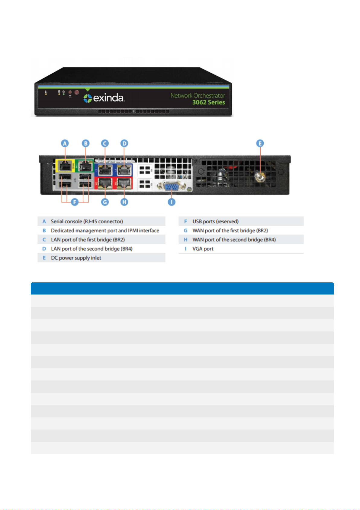
Network Orchestrator 3062 Series
Specification Details
Designed for Small Office
Supported Users Up to 1,600
Traffic Shaping
Shaping Throughput 150 Mbps
Concurrent Flow 45,000
New Connection Rate 4,000/s
Packets Per Second 45,000/s
Number of Traffic Policies 512
Traffic Acceleration
Acceleration Throughput 20 Mbps
Edge Cache Throughput 20 Mbps
Optimized Connections 2,000
Network Diagnostics
Screenshot 1: Front viewof the Exinda 3062.
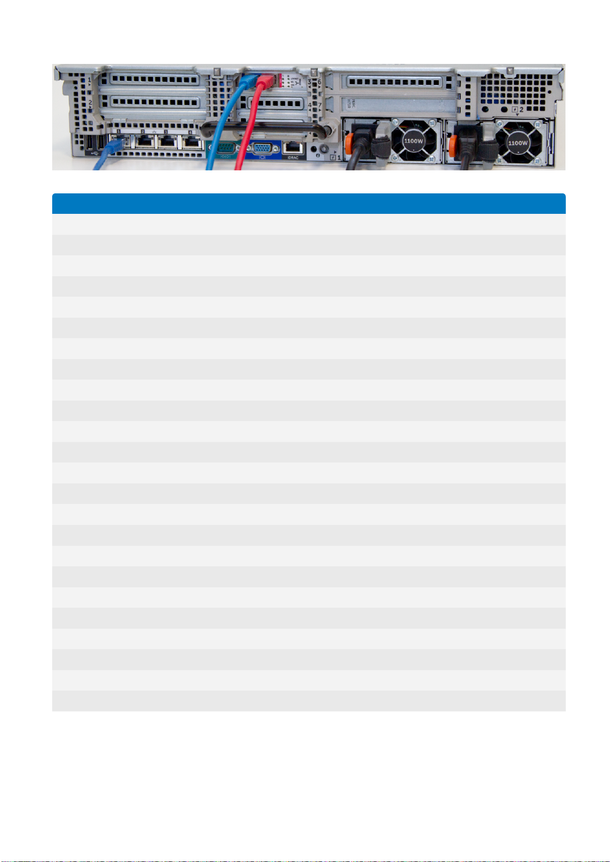
Screenshot 2: Rear viewof the Exinda 3062.
Exinda NetworkOrchestrator
1 Introduction |10
Specification Details
APS Objects 100
SLA Objects 100
PDF Reports 20
Hardware Specifications
Form Factor Desktop or 1U rack mount
Data Store/Cache Size 500 GB
NICs (Default) 2 Bridge Pairs, or 1 Bridge Pair plus 1 Management
NICs (expandable to) -
Redundant Power No
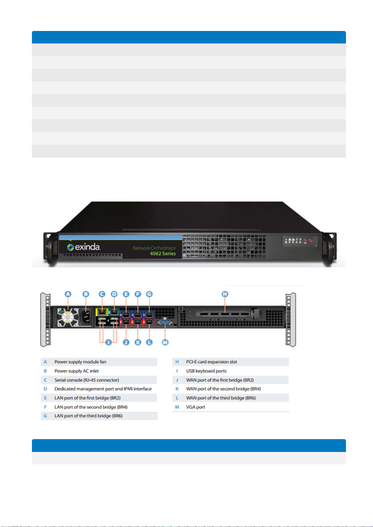
Network Orchestrator 4062 Series
Specification Details
Designed for Medium Office
Screenshot 3: Front viewof the Exinda4062.
Screenshot 4: Rear viewof the Exinda 4062.
Exinda NetworkOrchestrator
1 Introduction |11
Specification Details
Supported Users Up to 38,000
Traffic Shaping
Shaping Throughput 1 Gbps
Concurrent Flow 220,000
New Connection Rate 10,000/s
Packets Per Second 200,000/s
Number of Traffic Policies 1024
Traffic Acceleration
Acceleration Throughput 30 Mbps
Edge Cache Throughput 50 Mbps
Optimized Connections 6,000
Network Diagnostics
APS Objects 250
SLA Objects 250
PDF Reports 60
Hardware Specifications
Form Factor Desktop or 1U rack mount
Data Store/Cache Size 1 TB
NICs (Default) 3 Bridge Pairs, 1 Management, 1 Cluster (10GbE and 1Gb Fiber options available)
NICs (expandable to) 5 Bypass Bridges
Redundant Power Yes
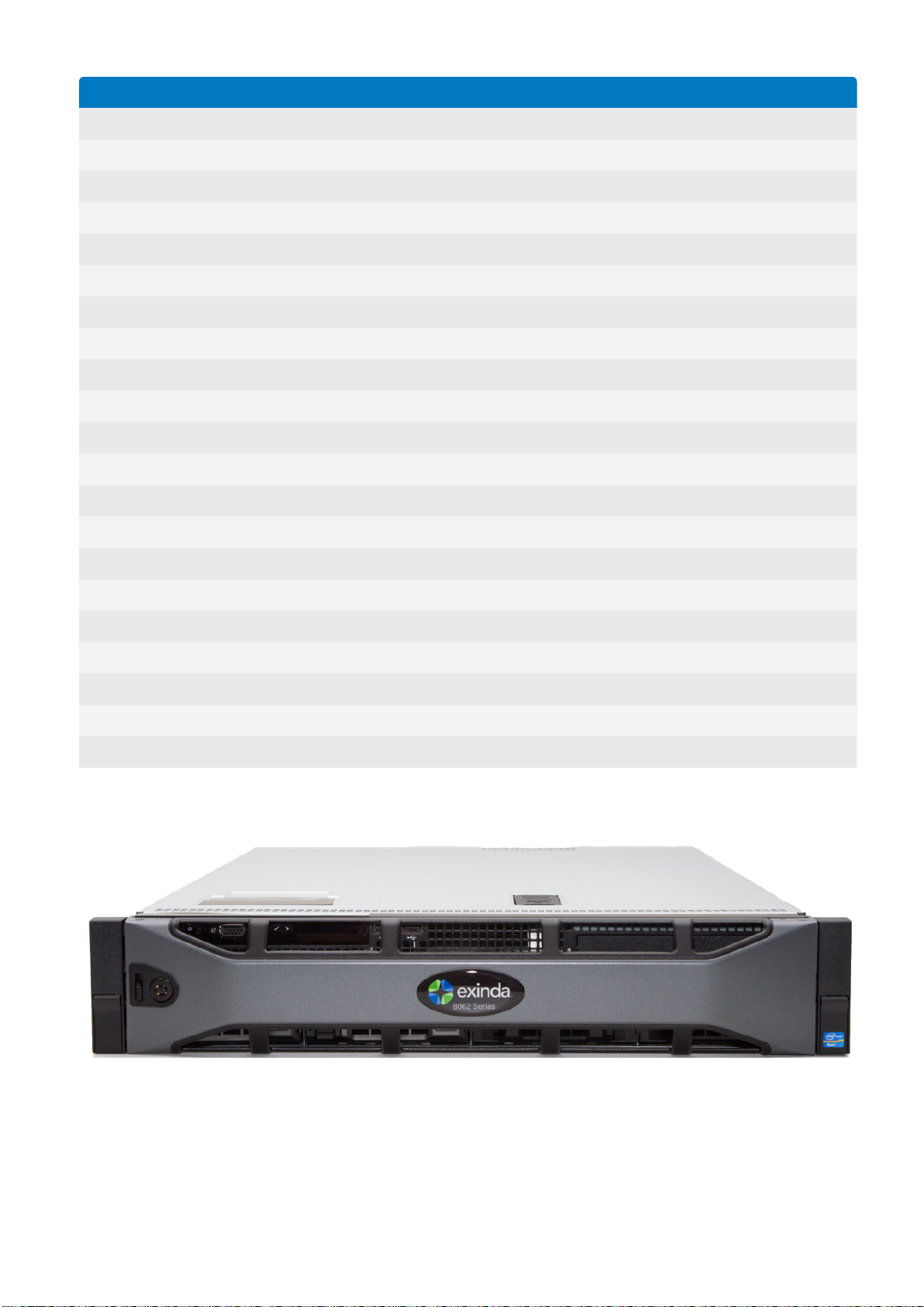
Network Orchestrator 8063 Series
Screenshot 5: Front viewof the Exinda 8062. The hardware of the Exinda 8062 and 8063 isthe same.
Screenshot 6:
Exinda NetworkOrchestrator
1 Introduction |12
Specification Details
Designed for Small to Medium Data Center
Supported Users Up to 250,000
Traffic Shaping
Shaping Throughput 5 Gbps
Concurrent Flow 500,000
New Connection Rate 20,000/s
Packets Per Second 650,000/s
Number of Traffic Policies 2048
Traffic Acceleration
Acceleration Throughput 150 Mbps
Edge Cache Throughput 175 Mbps
Optimized Connections 25,000
Network Diagnostics
APS Objects 300
SLA Objects 300
PDF Reports 100
Hardware Specifications
Form Factor Desktop or 1U rack mount
Data Store/Cache Size 2 TB, RAID 10
Memory 32 GB
NICs (Default) 1 management, 1 cluster, IPMI support
Interface NIC Slots 1 half height occupied, 1 full height
NICs (expandable to) 4 bypass bridges
Redundant Power Yes
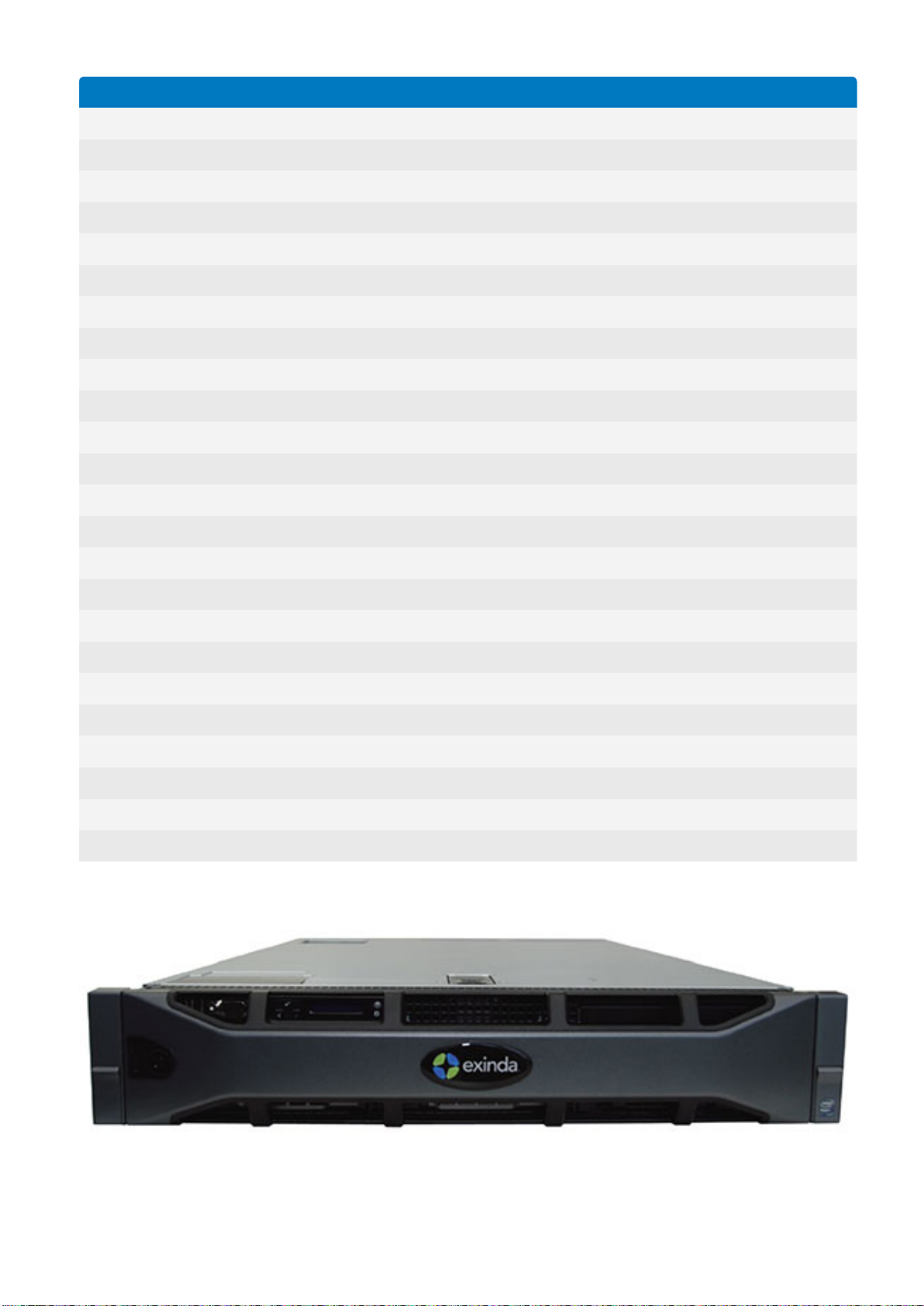
Network Orchestrator 10063 Series
Screenshot 7: Front viewof the Exinda 10062. The hardware of the Exinda10062 and 10063 is the same.
Exinda NetworkOrchestrator
1 Introduction |13
Screenshot 8: Rear viewof the Exinda 10062. The hardware of the Exinda10062 and 10063 is same.
Specification Details
Designed for Medium to Large Data Center
Supported Users Up to 400,000
Traffic Shaping
Shaping Throughput 10 Gbps
Concurrent Flow 1,200,000
New Connection Rate 32,000/s
Packets Per Second 1,400,000/s
Number of Traffic Policies 4096
Traffic Acceleration
Acceleration Throughput 500 Mbps
Edge Cache Throughput 250 Mbps
Optimized Connections 32,000
Network Diagnostics
APS Objects 300
SLA Objects 300
PDF Reports 100
Hardware Specifications
Form Factor Desktop or 2U rack mount
Data Store/Cache Size 1.8 TB, RAID 10
Memory 64 GB
NICs (Default) 1 management, 3 extra on-board interfaces, 1 IPMI
Interface NIC Slots 3 half height, 2 full height
NICs (expandable to) 10 bypass bridges
Redundant Power Yes
Exinda NetworkOrchestrator
1 Introduction |14

Network Orchestrator 12063 Series
Specification Details
Designed for Large Data Center
Supported Users Up to 600,000
Traffic Shaping
Shaping Throughput 15 Gbps
Concurrent Flow 1,800,000
New Connection Rate 38,000/s
Packets Per Second 1,800,000/s
Number of Traffic Policies 4096
Traffic Acceleration
Acceleration Throughput 2 Gbps
Edge Cache Throughput 500 Mbps
Optimized Connections 49,000
Network Diagnostics
APS Objects 400
SLA Objects 400
PDF Reports 150
Hardware Specifications
Form Factor Desktop or 2U rack mount
Data Store/Cache Size SSD 1.6 TB, RAID 2
Memory 256 GB
NICs (Default) 1 management, 3 extra on-board interfaces, 1 IPMI
Interface NIC Slots 4 half height, 3 full height
NICs (expandable to) 18 bypass bridges
Redundant Power Yes
1.4.2Exinda virtual appliances
The virtual Exinda Network Orchestrator provides the same monitoring, reporting and control features as the Exinda
hardware appliances. Capacity is determined by a combination of licensing and underlying hardware.
Exinda Virtual
A virtual Exinda Network Orchestrator runs on a host machine under a hypervisor, using dedicated resources. The
minimum dedicated hypervisor hardware requirements are listed in the table below:
Exinda NetworkOrchestrator
1 Introduction |15

Model EXNV-
3062
EXNV4062
EXNV8063
EXNV-10063 EXNV-12063
CPU (# x GHz) 4 x 2.0 4 x 2.4 8 x 2.4 12 x 2.4 (if license <=
300M)
24 x 2.4 (if license >
300M)
12 x 2.4 (if license <=
300M)
24 x 2.4 (if license >
300M)
Memory (GB) 6 8 32 64 64
Disk Space
(GB)
250 250 500 500 2000
Requirements:
hardware series The hardware model number.
software license The purchased license.
hardware version The platform configuration version.
bandwidth optimization | bandwidth acceleration / optimization The amount of bandwidth for acceleration, visibility and QoS.
Intel Xeon class, 64-bit CPU with VT Enabled
Hard drive space on a single disk
NOTE
Disk extending techniques are not supported on virtual appliances. Adding additional storage requires a hard disk.
1.5 Product naming conventions
Encoded within the Exinda Network Orchestrator model numbers are the features and licensing of the appliance.
This is the model number syntax:
<hardware series> <software license> <hardware version>-<bandwidth parameters>
Example:
Product model 8862-100/500 reflects the following information:
Series - 8000
Software license - x800 (acceleration, visibility and QoS control)
Hardware version - 6.2
Bandwidth - 100 Mbps (100 Mbps for acceleration, 500 Mbps for visibility and QoS)
Exinda NetworkOrchestrator
1 Introduction |16
2 Getting started
1 Install your ExindaAppliance
If you are using a Exinda Appliance hardware box, refer to Installing the Hardware Appliance into the Network.
Installing a Exinda Virtual Appliance depends on the hypervisor it supports, refer to Overview of the Virtual Appliances for
installation instructions on supported hypervisors.
2 Start monitoring the traffic
Start monitoring the traffic that passes through your Exinda Appliance. For more information, refer to Monitoring your network
(page 231).
If you are looking to monitor particular traffic patterns or usage, you can configure objects to support this.
Create network objects to monitor the traffic usage of branches, departments, classes of devices etc. A network object can
include one or more subnets and one or more IP addresses. For more information, refer to Adding network objects (page
172).
Configure active directory to identify traffic usage of users on the network. For more information, refer to Integrate with
Active Directory (page 499).
Create an application object if a new or custom application is not identified by the system. For more information, refer to
Adding application objects (page 190).
3 Configure Traffic Policy
Configuring traffic policy requires a bit of setup, however, the simplest solution is to run the Optimizer Policy Wizard. By
answering a few questions in the wizard, the system then sets up a traffic policy that effectively controls the general traffic
scenarios. See Optimizer Policy Tree to understand how the policy configuration works.
You can also customize the traffic policy and have multiple policies in place to match your requirements. For more information,
refer to Policies overview (page 362).
4 Create alerts and applicationperformance monitors
Set alerts on various aspects of the traffic. You can monitor the user experience of particular applications and set an alert when
the user experience becomes poor. You can monitor the availability of a site by pinging the IP address and define an alert when
the latency exceeds your specified threshold or when the packet loss is severe. You can monitor for particular activity that may
indicate an issue, such as asymmetric route detection, maximum accelerated connections exceeded, NIC collisions, or dropped
packets, and so on.
To monitor the user experience of particular applications, create an Application Performance Score object.
To monitor a particular IP address for availability, create an Site Service Level Agreements object.
The alerts are sent by email assuming the appliance is configured to send e-mail. For more information, refer to Email con-
figuration (page 491).
5 Find solutions and get notified
The Exinda appliance displays solutions and notifies you if certain undesirable thresholds are exceeded or if other notable traffic
patterns are identified so that you can take action to tune your network.
For more information, refer to Monitoring applications with the Exinda Solution Center (page 322).
For more information, refer to Alerts (page 577).
6 Control and accelerate traffic accordingly
Go back and tune traffic policy to control and accelerate traffic to ensure business critical traffic is ensured the bandwidth that is
needed, and that the traffic is prioritized and accelerated properly.
This getting started guide steps through the basic process of installing, configuring and using your Exinda Network
Orchestrator. Each step builds on the previous step and contains links torelevant help topics with detailed instructions to
get your Exinda up and running in your network environment.
2.1 WUIGuided Tour
To view an interactive slide show of the UI, go to Guided Tour
Exinda NetworkOrchestrator
2 Getting started | 17

2.2 Deployment options
Term Definition
In-path In-path describes a type of topology and refers to deploying an Exinda Appliance between network devices that
send and receive data packets to each other, like a switch and a router. When an Exinda Appliance is in-path, it
automatically inspects all packets traveling along its path.
Out-of-path An Exinda Appliance connected to only one network device is considered out-of-path. By default, that implies
network packets don't naturally travel through the Exinda Appliance to get to their destinations. For example,
connecting an Exinda Appliance to a switch or hub on the LAN. In this case, the Exinda Appliance behaves like any
other network client and requires specific protocols or modes to enable packet monitoring and inspection.
Inline In network terminology, an inline device receives packets and forwards them to their intended destination. Routers,
firewalls and switches are examples of inline devices. The inline designation also alerts you the device is critical to
network function. If the device goes down, network traffic is affected. In an in-path topology, an Exinda Appliance is
deployed Exinda Appliancesinline in the network.
Clustering Grouping Exinda Appliances together in systems to perform the same functions in each system or to mirror each
other. Example scenarios include failover, load balancing and multipath networks.
Application
Acceleration
Application Acceleration is an intelligent network enhancer based on a set of proprietary algorithms embedded in
an Exinda Appliance. It reduces latency, increases network throughput, frees network capacity and a whole lot more.
To get the benefits of Application Acceleration, you need at least two Exinda Appliances.
An Exinda Appliance fits almost anywhere in your network environment. As a general rule, anywhere network packets
move from one device to another, whether via physical cables or virtualization, you can plug in an Exinda Appliance.
In this section of the guide, you'll walk-through the most common Exinda Appliance deployments.
Many of the example topologies you'll see are used by Exinda customers from various industries around the globe. The
list is by no means exhaustive, but you'll undoubtedly find something similar enough to your network environment for
you to build on.
2.2.1Key terms
Throughout the deployment options section, you'll see common networking terms you may already be familiar with.
Depending on your background and experience, youmay have seen the terms used slightly differently than the way
they're used in this guide.
To make the deployment examples clear and concise, the terms and definitions are included here.
2.2.2Basic characteristics and behaviors of Exinda Appliances
All Exinda Appliance hardware models share some basic characteristics and behaviors.This list provides helpful
information to keep in mind while planning and implementing a deployment.
Every Exinda Appliance has at least one pair of hardware bypass ports marked LAN and WAN.
Exinda Appliance LAN and WAN ports failover to pass-through mode in the event of system failure or power loss.
It's best practice to deploy the Exinda Appliance powered off. This ensures the hardware bypass is working.
NOTE
There may be a short interruption to network connectivity while the Exinda appliance switches out of bypass mode
during boot-up. Although switching in and out of bypass takes less than a millisecond, this may force neighboring
equipment to renegotiate their layer 2 topology, which could take several seconds
Exinda NetworkOrchestrator
2 Getting started | 18
2.2.3In-path topologies
Exinda Appliances are often deployed between a core switch and a WAN/Internet router. In this type of deployment,
the Exinda Appliance is referred to as inline, which is a way to describe a network device in a primary network path that
receives packets and forwards them to their destinations. In this case, the Exinda Appliance receives packets from the
core switch and sends them to the Internet/WAN router and vice versa.
Screenshot 9: Inline deployment ofan ExindaAppliance
Usually,the WAN port on your Exinda appliance is cabled to the WAN/Internet router, using the crossover Ethernet cable.
And the LAN port on your Exinda appliance is cabled to the core switch, using the straight Ethernet cable. If your
appliance has a dedicated management port,it also needs to be cabled to an internal switch using an Ethernet cable.
Both cables are shipped along with the appliance.
For more information, refer to Basic characteristics and behaviors of Exinda Appliances (page 18).
For specific information about your model, download its Quick Start Guide.
Once all Ethernet cables are in place, power the Exinda Appliance off and ensure the network connectivity. Then, power
on the Exinda Appliance, let it fully boot and ensure network connectivity.
The following topics describe how to configure and operate your Exinda Appliance within various in-path topologies.
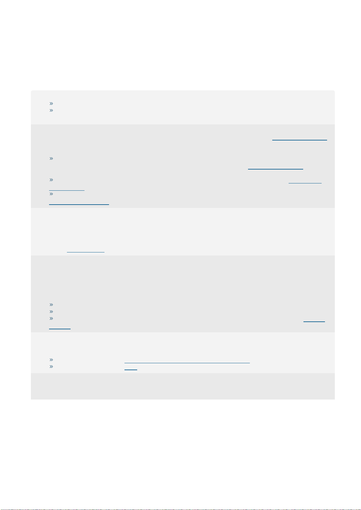
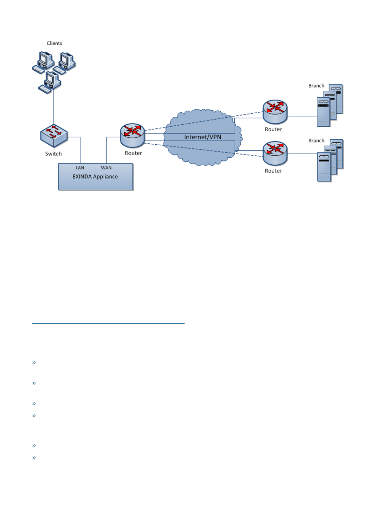
Main site Internet link topology: single site with one Exinda Appliance
A simple way to monitor network traffic between the Internet and your local network, is to plug-in your Exinda Appliance
on the network path between your network users and the router, firewall or other gateway device that controls access
from your LAN to the Internet.
Exinda NetworkOrchestrator
2 Getting started | 19
Screenshot 10: Mainsite internet link deployment
The topology depicted in the diagram shows a basic Exinda Appliance network deployment with several sets of users
from a Main Site and Branch sites linking over the Internet. In Exinda terminology, this general configuration is aptly
named, Main Site Internet Link topology.
The left side of the diagram labeled "Main Site" represents a typical office environment, comprising network users, a
switch, a router and an Exinda Appliance.
The middle of the diagram represents the Internet and the right side of the diagram represents all the people,
machines and programs that want access to servers and applications hosted at the Main Site.
In this setup, the Exinda Appliance is connected to the switch and the router on the Main Site. So network traffic
emanating from the Main Site to the Internet and traffic from the Internet to the Main Site must pass through the Exinda
Appliance.
With the Exinda Appliance deployed between the switch and the router, you get visibility toall the traffic entering and
leaving the Main Site network via the router.
Installing the Exinda Appliance in a main site internet link topology
This install is straightforward and requires just a few steps.
The high level plan is to plug your Exinda Appliance inline between the switch and router.
In most network environments, the switch will already be physically connected to the router. We're going to temporarily
disconnect the switch and router from each other, insert the Exinda Appliance between them and reconnect
everything with the Exinda Appliance firmly in the middle.
NOTE
In network terminology, an "inline" device receives packets and forwards them to their intended destination.
Routers, switches and firewalls are examples of inline devices. The inline designation also alerts you that the device
is critical to network function. If the device goes down, network traffic is affected.
1. Connect the WAN port to your router/firewall using a crossover cable.
2. Connect the LAN port to the LAN switch.
3. Leave the Exinda Appliance powered off.
Exinda NetworkOrchestrator
2 Getting started | 20

4. Check for Internet connectivity.
5. Turn on the Exinda Appliance and check for Internet connectivity again.
There are a few Exinda Appliance basics to keep in mind while planning a deployment. For more information, refer to
Basic characteristics and behaviors of Exinda Appliances (page 18).
Capabilities provided by a main site internet link topology
In a Main Site Internet Link topology, an Exinda Appliance:
Monitors all network traffic going to and returning from the Internet/WAN.
Monitors application specific network traffic going to and returning from the Internet.
Controls network traffic on the Main Site by allocating bandwidth to Main Site network users and setting priorities for
Internet-based applications accessed by Main Site network users.
Monitors and controls network traffic from Branch users and the Internet to servers and applications hosted on the
Main Site.
Limitations of the main site internet link topology
Monitoring and controlling Branch Site traffic to the Internet is impossible because the Exinda Appliance is not
inline between the branch offices and the Internet. If you want to monitor and control network traffic for a geographically dispersed user base that connects to the Internet through multiple routers outside your LAN, use a different
deployment strategy.
One of Exinda's top features is Application Acceleration. With only one Exinda Appliance deployed, Application
Acceleration isn't available because it requires at least two Exinda Appliances.
Overcoming the limitations of the main site internet link topology
If you only have one Exinda Appliance but need to monitor and control network traffic to the Internet from users outside the Main Site, disable direct access to the Internet for branch offices and route all Internet-bound traffic through
the Main Site.
NOTE
Routing Internet-bound traffic from users outside your Main Site through the Main Site router introduces an extra leg
of travel for network packets and could cause a spike in the Main Site's router utilization.
Install an Exinda Appliance at each branch. Essentially, you replicate the Main Site Internet Link topology at each
branch. Installing multiple Exinda Appliances into your network environment allows you to implement Exinda's proprietary, performance-boosting Application Acceleration technology.
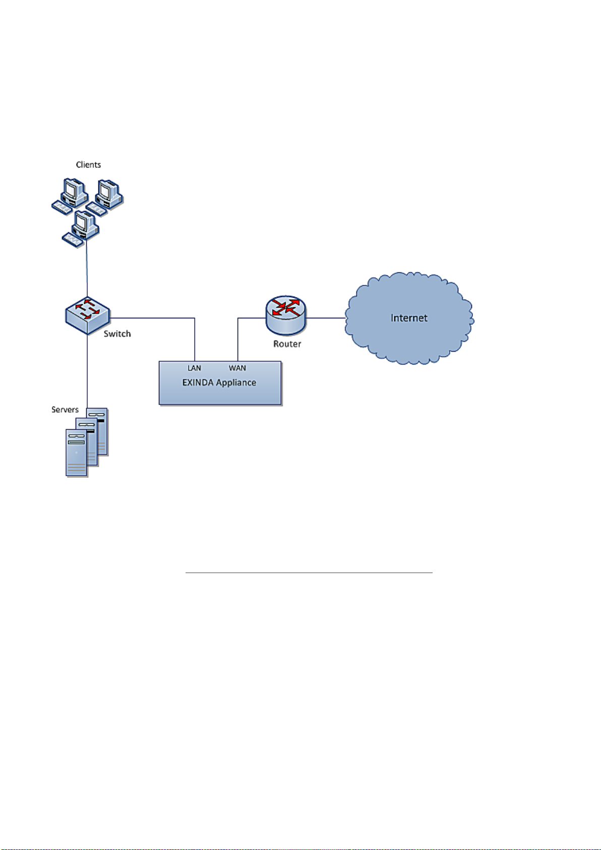
Main site WAN link topology: multiple sites with one Exinda Appliance
This topology is used to monitor and control Internet and WAN traffic in the main site and WAN traffic from the branch
offices. The Exinda Appliance monitors and controls Internet and WAN traffic on the main site and WAN traffic from
branch offices. The Exinda guarantees traffic for the WAN and treats applications and users from different branch offices
with different priorities.
Exinda NetworkOrchestrator
2 Getting started | 21
Screenshot 11: MainSite WAN Link topology deployment
Installing the Exinda Appliance in a main site WAN link topology
Plug your Exinda Appliance in line between the switch and router or firewall. If you have a VPN, refer to Topologies with
VPNs.
1. Connect the WAN port to your router/firewall using a crossover cable.
2. Connect the LAN port into the LAN switch.
3. Leave the Exinda Appliance powered off.
4. Check for Internet connectivity.
5. Turn on the Exinda Appliance and check for Internet connectivity again.
There are a few Exinda Appliance basics to keep in mind while planning a deployment. For more information, refer to
Basic characteristics and behaviors of Exinda Appliances (page 18).
Capabilities provided by the main site WAN link topology
In this topology, the Exinda appliance:
Monitors all traffic utilization and all applications tothe Internet. You can distinguish between business relevant
traffic and traffic used for recreational purposes.
Monitors usage of Internet and WAN traffic, e.g., how much of the link is being used by the Internet and each
branch office?
Monitors and controls individual applications and users from each branch office.
Controls all traffic traversing the link. Allocate bandwidth to WAN and Internet applications.
Limitations of the main site WAN link topology
Application Acceleration is not possible with a single appliance.
If a branch office connects to the Internet directly, the branch link cannot be monitored and controlled.
Exinda NetworkOrchestrator
2 Getting started | 22
Overcoming the limitations of the main site WAN link topology
If you need to monitor and control network traffic to the Internet from users outside the Main Site, disable direct
access to the Internet for branch offices and route all Internet-bound traffic through the Main Site.
NOTE
Routing Internet-bound traffic from users outside your Main Site through the Main Site router introduces an extra leg
of travel for network packets and could cause a spike in the Main Site's router utilization.
Install an Exinda Appliance at each branch. Essentially, you replicate the Main Site Internet Link topology at each
branch. Installing multiple Exinda Appliances into your network environment allows you to implement Exinda's proprietary, performance-boosting Application Acceleration technology.
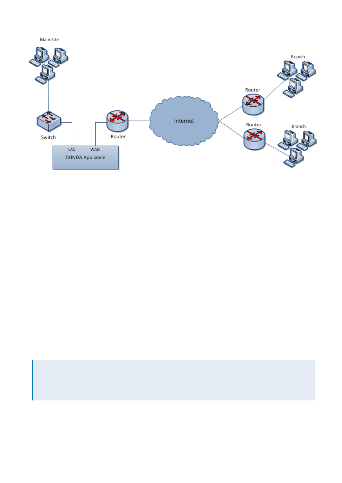
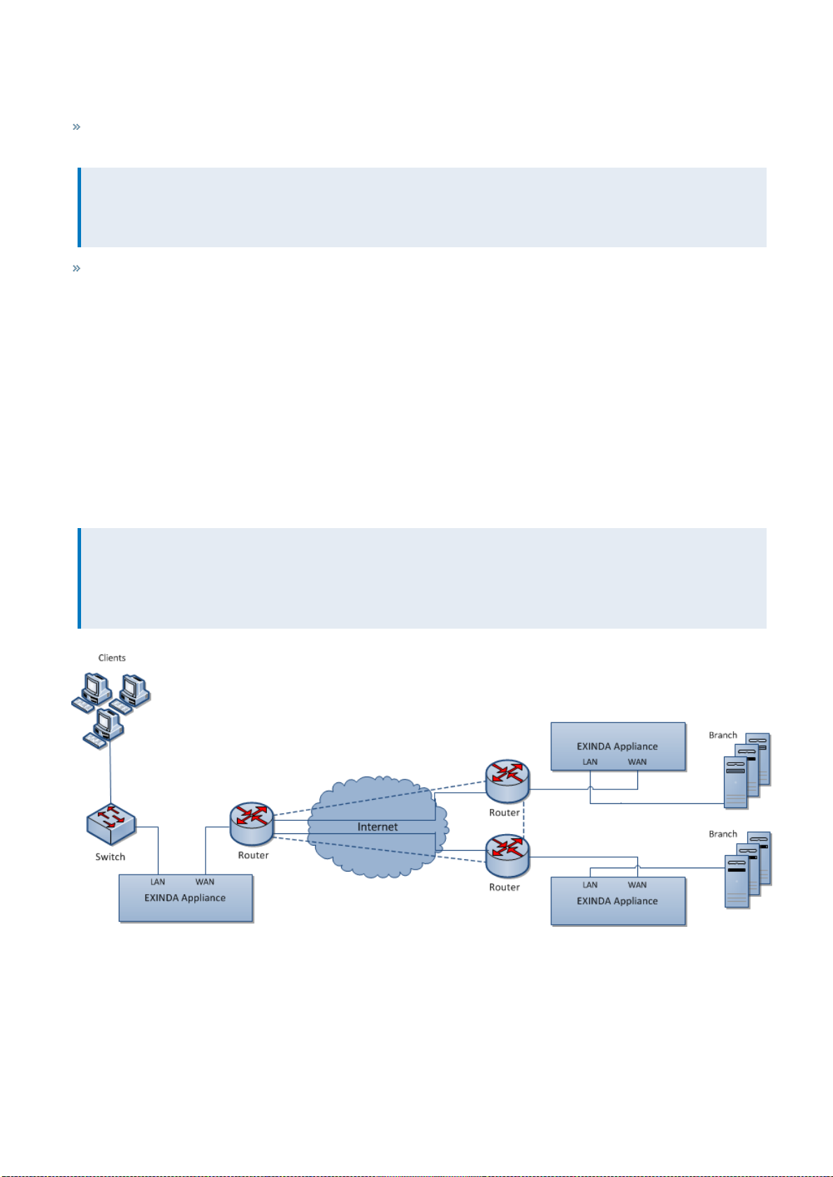
Distributed branch topology: multiple sites with multiple Exinda Appliances
Deploying multiple Exinda Appliances provides a lot of flexibility for monitoring and shaping network traffic across
multiple network sites. You also gain the ability to enable Exinda's Application Acceleration feature if your Exinda
Appliance model supports it.
This topology requires at least two Exinda Appliances. In the network diagram below, there are three Exindas, once at
each site. The sites are connected to the Internet and to each other via direct routes.
All the network traffic at each site passes through an Exinda Appliance on its way to and from the Internet and WAN. The
Exindas may work together to enhance network performance and accelerate specific network traffic.
NOTE
An acceleration license is required to take advantage of Application Acceleration. Check the Exinda hardware
appliances and technical specifications to make sure your Exinda Appliance model supports Application
Acceleration.
Screenshot 12: Distributed Branchtopology deployment
Installing the Exinda Appliance in a distributed branch topology
At each site:
Exinda NetworkOrchestrator
2 Getting started | 23
1. Connect the WAN port to your router/firewall using a crossover cable.
2. Connect the LAN port to the LAN switch.
3. Leave the Exinda Appliance powered off.
4. Check for Internet connectivity.
5. Turn on the Exinda Appliance and check for Internet connectivity again.
There are a few Exinda Appliance basics to keep in mind while planning a deployment. For more information, refer to
Basic characteristics and behaviors of Exinda Appliances (page 18).
Capabilities provided by a distributed branch topology
In this topology, the Exinda appliances:
Monitor and control all traffic to and from the Internet and WAN.
May accelerate traffic between all WAN sites.
Monitor distribution of application traffic between all sites.
Prioritize and manage application performance in a fully meshed environment.
Control or block P2P and recreational applications site-wide.
Limitation of the distributed branch topology
None. This is the most flexible and robust topology.
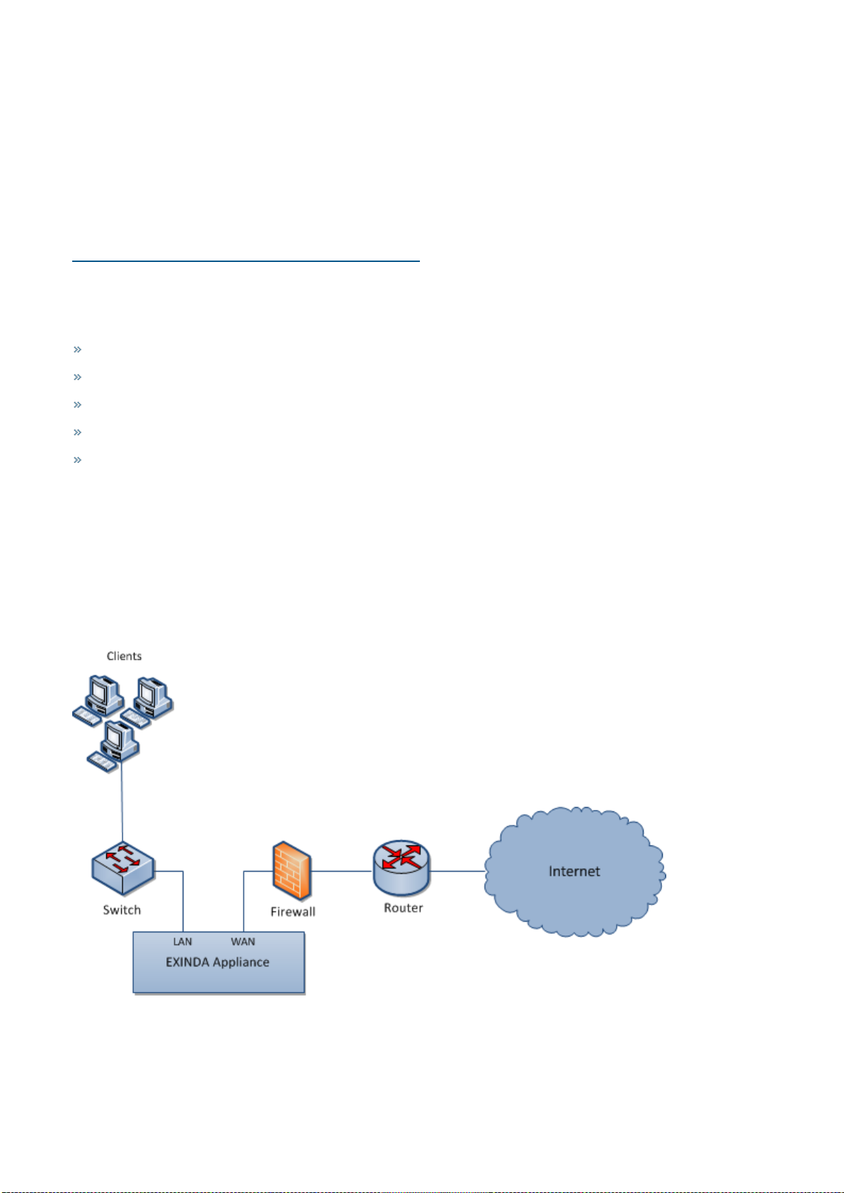
Topologies with firewalls: Exinda Appliance in a network with a firewall
Firewall topologies vary significantly. Typically, an Exinda appliance is deployed between the switch and internal
interface of the firewall. This ensures the Exinda Appliance sees all hosts on the LAN.
Screenshot 13: Topologywith firewalls
Exinda NetworkOrchestrator
2 Getting started | 24
NOTE
Placing the Exinda Appliance between the router and external interface of the firewall will only monitor
applications and IP addresses present on the external interface of the firewall. So, if your firewall performs Network
Address Translation (NAT), the Exinda will only see the firewall's external IP address as the source address of the
monitored flows.
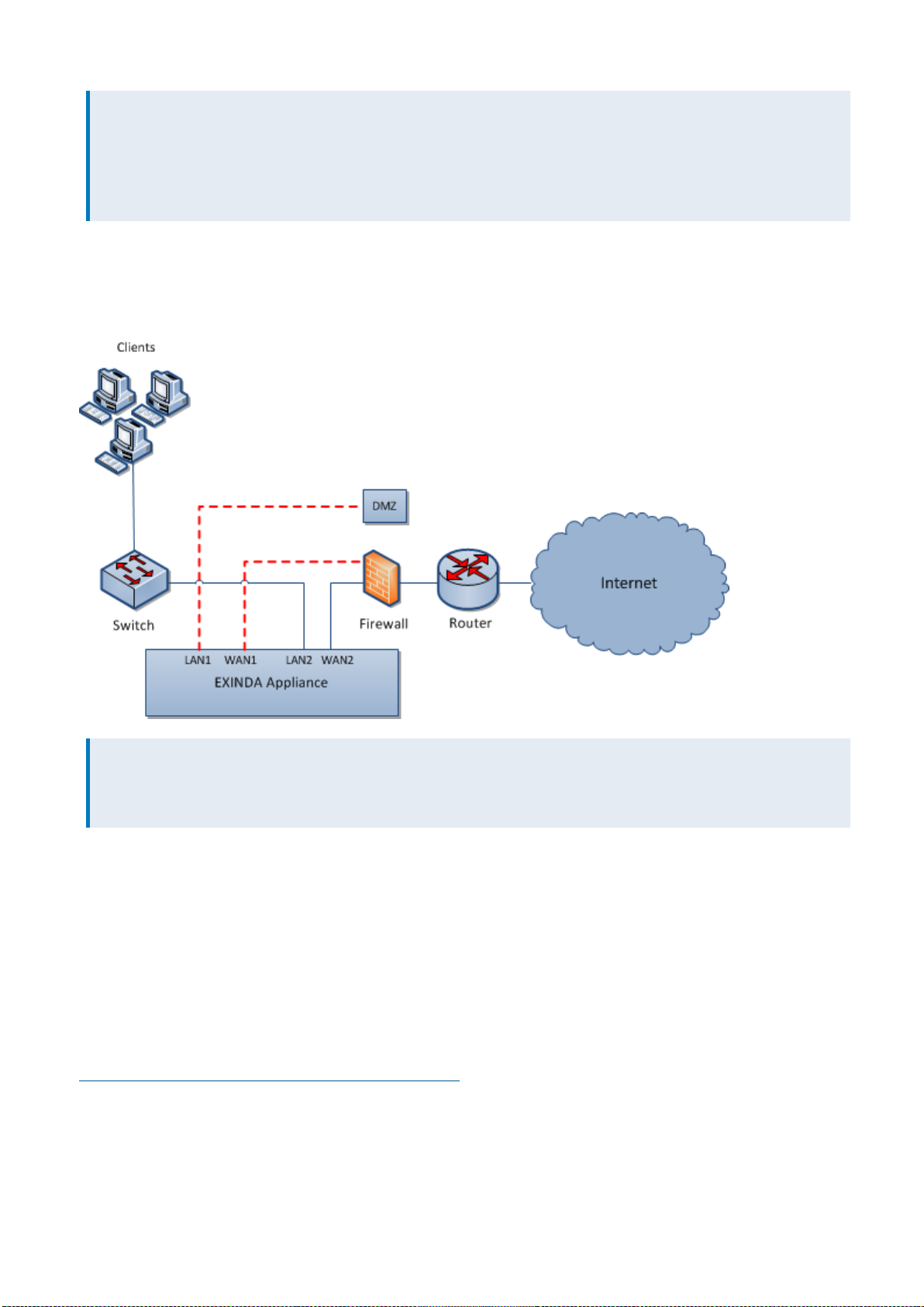
Deploying an Exinda Appliance in-path of a DMZ
The Exinda appliance can be deployed in-path of a DMZ, allowing monitoring, optimization and Application
Acceleration of traffic to and from the DMZ.
NOTE
Define a network object called DMZ and mark it as "Internal," so the Exinda appliance can ignore all traffic between
the local LAN and the DMZ.
Installing an Exinda Appliance in a network environment with a firewall
1. Enable the appropriate bridges on the IP Address configuration page.
2. Connect Exinda WAN2 into your router/firewall using a crossover cable.
3. Connect Exinda LAN2 into the LAN switch.
4. Connect Exinda LAN1 into the DMZ switch or host.
5. Connect Exinda WAN1 in the DMZ interface of the firewall using a crossover cable.
There are a few Exinda Appliance basics to keep in mind while planning a deployment. For more information, refer to
Basic characteristics and behaviors of Exinda Appliances (page 18).
Topologies with VPNs: Exinda Appliance in a network with a VPN
The typical deployment places an Exinda Appliance between an internal LAN switch and VPN terminator. This allows
the Exinda tomonitor and optimize traffic before it's encrypted and transported across the VPN tunnel.
Exinda NetworkOrchestrator
2 Getting started | 25
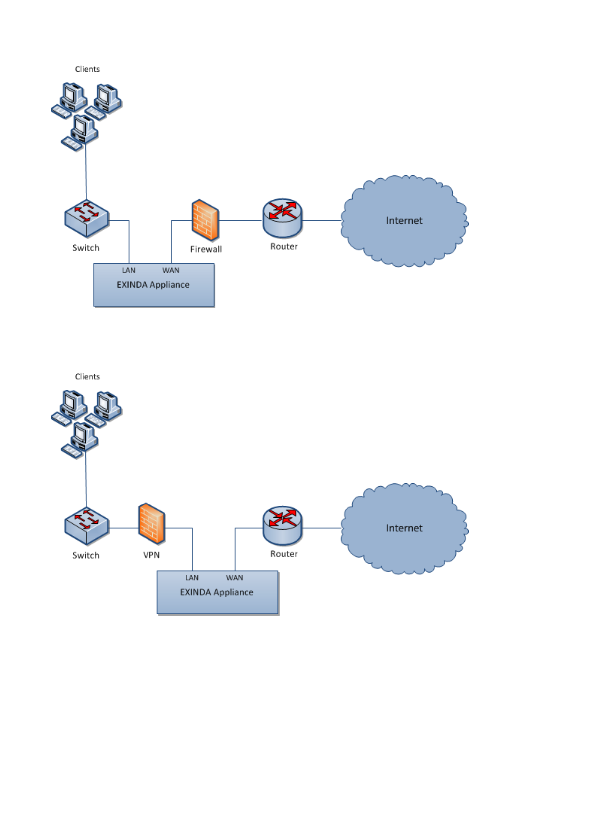
Screenshot 14: Topologies with VPNs deployment - Scenario 1
In scenarios where the Exinda Appliance is placed between the VPN terminator and the router, the Exinda Appliance
sees only encrypted tunnel traffic.
Screenshot 15: Topologies with VPNs deployment - Scenario 2
Installing an Exinda Appliance in a network environment with a VPN
Scenario1:
1. Connect the Exinda WAN port into the internal interface of the VPN terminator using a crossover cable.
2. Connect the Exinda LAN port into the LAN switch.
Scenario2:
Exinda NetworkOrchestrator
2 Getting started | 26
1. Connect the Exinda WAN port into the internal interface of the router.
2. Connect the Exinda LAN port into the external interface of the VPN terminator using a crossover cable.
3. Connect an Exinda unbridged interface (e.g., eth1 on a 4060) into the LAN switch and configure an address to man-
age the appliance.
There are a few Exinda Appliance basics to keep in mind while planning a deployment. For more information, refer to
Basic characteristics and behaviors of Exinda Appliances (page 18).
Capabilities of an Exinda Appliance in a network environment with a VPN
In VPN scenario 2, the Exinda Appliance:
Monitors and controls any unencrypted traffic to the WAN and Internet.
Monitors and prioritizes encrypted traffic between other VPN terminator sites. Only a single IP address will be visible
per site.
Limitations of an Exinda Appliance in a network environment with a VPN
In VPN scenario 2 the Exinda appliance cannot monitor and prioritize the encrypted traffic by application, internal hosts
and servers.
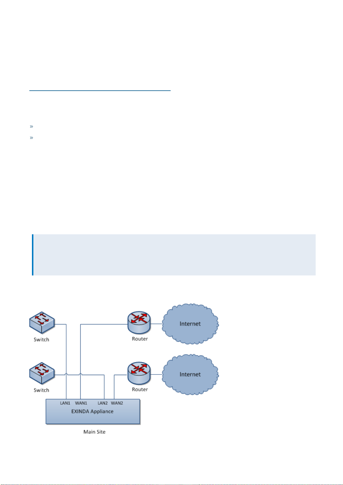
Multiple link topology: Exinda Appliance in a network with multiple WAN connections
Some Exinda Appliances support multiple bridges, allowing multiple connection links through the appliance. This
supports a single Exinda Appliance topology which allows monitoring and controlling Internet traffic to and from the
main site as well as WAN traffic.
NOTE
We recommend using a bypass capable bridge. In the event of hardware failure, the Ethernet bypass allows your
network to function even if the equipment doesn't. But keep in mind, for this strategy to be effective, once it's
installed the bridge must be enabled on the IP Address configuration page.
All Exinda Appliances support this topology, but some appliances only have a single bypass enabled bridge to provide
Ethernet bypass in the event of hardware failure.
Screenshot 16: Multiple Linktopology deployment
Exinda NetworkOrchestrator
2 Getting started | 27
Installing and Exinda Appliance in a multiple link topology
Plug your Exinda Appliance inline between the switch and router or firewall.
1. Connect the Exinda WAN1 port into your WAN router/firewall using a crossover cable.
2. Connect the Exinda LAN1 port into the LAN switch.
3. Connect the Exinda WAN2 port into your Internet router/firewall using a crossover cable.
4. Connect the Exinda LAN2 port into the LAN switch.
There are a few Exinda Appliance basics to keep in mind while planning a deployment. For more information, refer to
Basic characteristics and behaviors of Exinda Appliances (page 18).
2.2.4Out-of-path topologies
An Exinda Appliance connected toonly one network device is considered out-of-path. By default, that implies network
packets don't naturally travel through the Exinda Appliance to get to their destinations. For example, connecting an
Exinda Appliance to a switch or hub on the LAN. In this case, the Exinda Appliance behaves like any other network client
and requires specific protocols or modes to enable packet monitoring and inspection.
Learn how Exinda Appliances operate within an out-of-path topology.
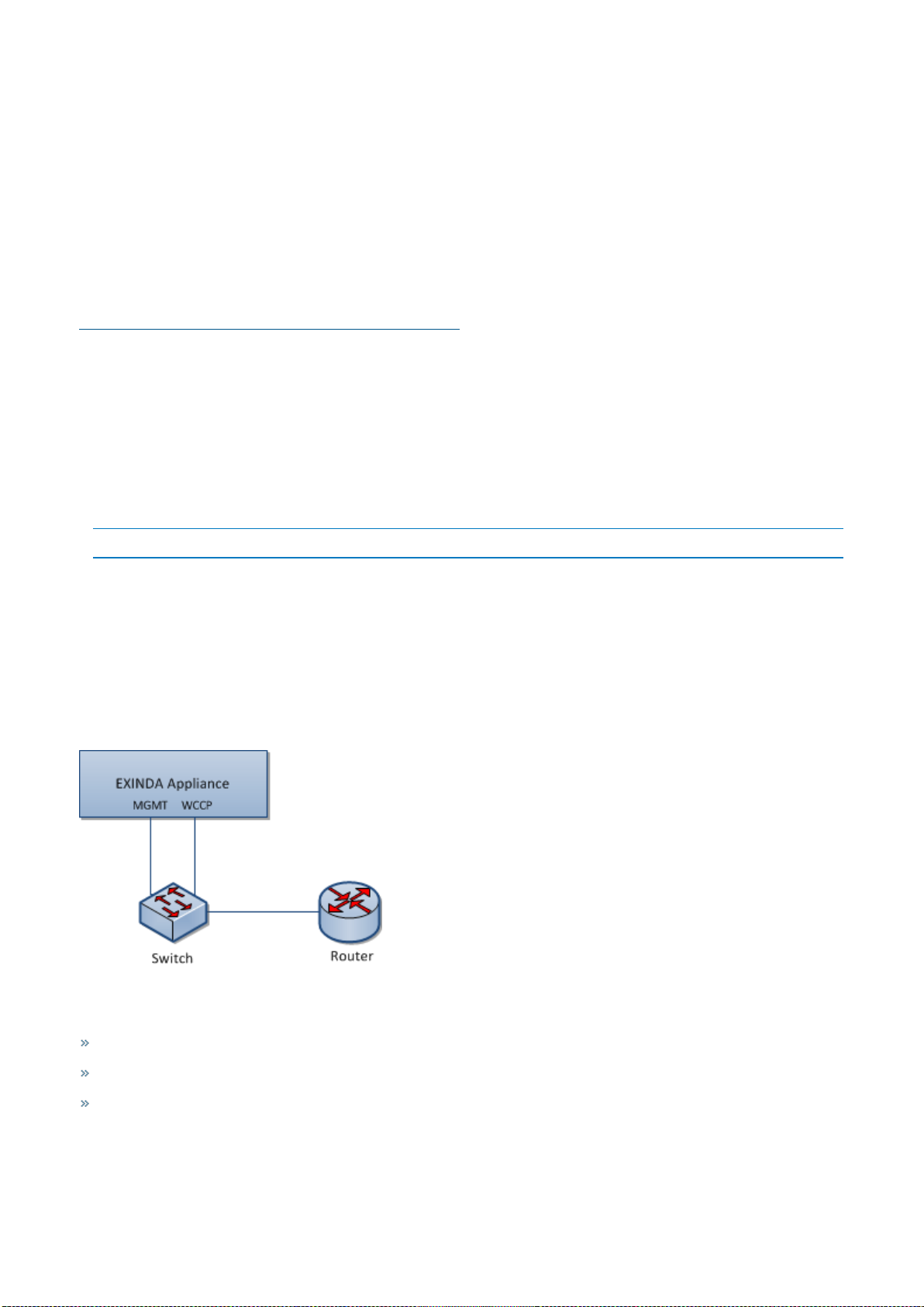
Accelerating traffic with Web Cache Communication Protocol (WCCP)
An Exinda appliance can accelerate traffic routed using Web Cache Communication Protocol (WCCP) v2. Use this
topology when you want application acceleration, but do not wish to install the Exinda appliance inline.
To use WCCP v2 to route traffic to the Exinda appliance, configure the router and the Exinda appliance. To enable WCCP
on the appliance, use the WCCP CLI command to assign an interface for WCCP. If you require authentication on the
router, add the router's password on the appliance. Configured network objects determine the traffic direction.
Screenshot 17: Accelerate traffic with WCCP
WCCP out-of-path deployment includes a few limitations:
Only TCP applications can be routed to the Exinda.
The Router must support WCCP v2.
Additional load is placed on the router.
Exinda NetworkOrchestrator
2 Getting started | 28

Configuring the router to use WCCP
Consult the documentation of your router for instructions on configuring WCCP.
For Ciscorouters running firmware release 12.0T, refer to http://www.cisco.com/en/US/docs/ios/12_0t/12_
0t3/feature/guide/wccp.html
Enabling WCCP on the Exinda appliance
1. Access the CLI from the Web UI or via SSH, Telnet, or Serial Port in privileged (enable) mode and configure mode (con-
figure terminal).
2. Assign an interface for WCCP.
a. For a unicast configuration, set the router IP address for each WCCP v2 service.
wccp interface <interface-name>
wccp service <service-group number> router <router-IP-address>
EXAMPLE
Assign interface eth2 to WCCP v2 traffic with service class 10 from 192.168.0.1
wccp interface eth2
wccp service 10 router 192.168.0.1
NOTE
Ensure you set the router to the highest IP address available on the router.
b. For a multicast configuration, set a group-address for WCCP v2 traffic.
(config)# wccp interface <interface-name>
(config)# wccp service <service-group number> group-address <multicastaddress>
EXAMPLE
Assign interface eth2 to WCCP v2 traffic with service class 10 from multicast address 192.168.0.1
wccp interface eth2
wccp service 10 group-address 224.1.1.1
3. If a password has been configured for a service on the router, add that password on the Exinda.
(config) # wccp service <service-group number> password <password>
How network objects are used to determine traffic direction
For an Exinda appliance to determine traffic direction, you must define all internal subnets as internal network objects.
Network objects can be edited from Configuration > Objects> Network> Network Objects.
After identifying the subnets as internal network objects, as traffic passes through the appliance, the appliance looks at
the source IP and destination IP of the packet and matches them to the network objects to determine whether the
source IP and destination IP should be considered internal or external, determining the packet direction.
Consider the following rules when comparing the location of an IP packet relative to an internal network object:
Exinda NetworkOrchestrator
2 Getting started | 29
Source IP DestinationIP Result
Internal External Packet is classified as outbound traffic.
External Internal Packet is classified as inbound traffic.
Internal Internal Traffic flowing from the lower IP to the higher IP is classified as outbound
traffic.
Traffic flowing from the higher IP to the lower IP is classified as inbound traffic.
External External Traffic flowing from the lower IP to the higher IP is classified as outbound
traffic.
Traffic flowing from the higher IP to the lower IP is classified as inbound traffic.
To display the status of the WCCP service and verify that the connection between the appliance and the
router is active
Use CLI to type show wccp service <service-group number>. The status of the service is displayed
with the Router and Appliance IP addresses. If any error messages are displayed beside an IP address, resolve the issue
with the configuration and re-verify the service.
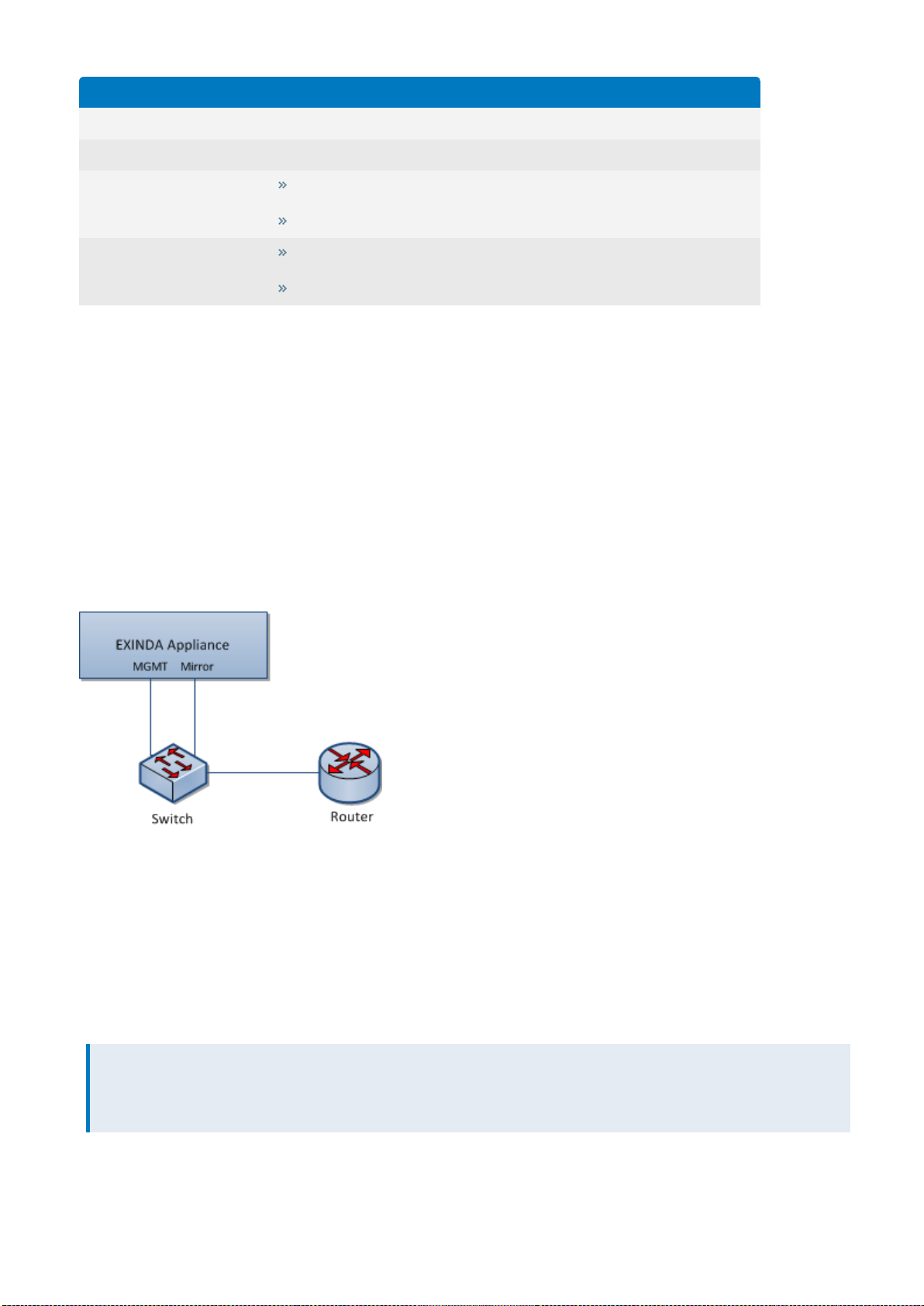
Overview of SPANand mirror port monitoring
An Exinda Appliance can operate out-of-path or ON-LAN mode with any hub or switch that supports port mirroring or
SPAN ports. Use this topology when you need to monitor traffic without installing the Exinda Appliance inline. The
Exinda Appliance monitors and reports on all applications present on the SPAN/mirror port. It enables regular network
audits and provides great flexibility in restricted and complex network environments.
Screenshot 18: Topologydiagram showinghow to cable MGMT and Mirror ports for Mirror/SPAN port monitoring.
To configure Mirror/SPAN port monitoring, perform the following tasks:
1. Configuring Mirror Port Mode.
2. Enabling Mirror/SPAN traffic monitoring.
3. Configuring internal subnets as internal network objects.
After enabling Mirror/SPAN monitoring and defining the appropriate Internal Network Objects, the Exinda appliance
monitors traffic received on the Mirror/SPAN receiving port as if it were inline.
NOTE
Exinda interface reports will be blank because the Exinda Appliance has no insight into packet direction at the
interface level.
Exinda NetworkOrchestrator
2 Getting started | 30
 Loading...