

Page 1
INSTALLATION & OPERATING
INSTRUCTIONS
SCR 100 SERIES
INDUSTRIAL BATTERY CHARGERS
Page 2

Page 3
This Warranty Agreement entered into between GNB Technologies, "GNB", and the Original User in respect to GNB
electric vehicle
battery chargers for electric vehicle usage.
1.0 GENERAL
GNB warrants that each new electric vehicle battery charger supplied by it, is of good workmanship and is free from any inherent
mechanical defects, provided:
1.1 The product is installed and operated in accordance with generally accepted industrial standards and in accordance with
the printed instructions supplied with the charger.
1.2 The charger is used under conditions for which it was designed and is not subject to misuse, negligence or accident.
1.3 The charger receives proper care, protection, and maintenance under supervision of competent personnel.
1.4 The charger is used within the published performance rating for the unit involved.
1.5 The charger is used exclusively by the original user and by no other persons.
2.0 PERSONS COVERED
This warranty is extended by GNB only to the original user who purchases or leases a new charger product from GNB or one
of its authorized representatives. The product purchased or leased under this agreement shall be used exclusively by the origi nal user and its employees and by no other persons and, therefore, there shall be no third party beneficiary to this warranty.
3.0 WARRANTY PERIOD
The charger is warranted for four (4) years from the date of manufacture as determined by the product serial number, with
the following exceptions:
3.1 Power transformers, SCR's and silicon diodes are warranted for ten (10) years from the date of manufacture of the
charger(s) of which they are a part.
3.2 Primary switch contacts, fuses, bulbs, and filters are not warranted unless found to be defective prior to use.
4.0 LIMITATION OF REMEDY
Any claimed defect is subject to GNB's inspection and judgment, after the defective product has been returned by the o
riginal
user at its expense to GNB’s designated point of shipment.
4.1
GNB’s liability is
limited
to
the repair of the defect or, at GNB’s option, the replacement of the defective parts. During the initial
three
(3)
years of charger
warranty
period, GNB will bear all parts and labor costs of such repair or replacement. During year
four (4) of the warranty
, GNB
will
only cover parts, no labor or travel will be provided by GNB. During the last six (6) years
of the ten
(10)
year warranty
on
power transformers, SCR's and silicon diodes, GNB will bear costs of parts replacement only;
no labor or other services will be provided by GNB. GNB shall not be obligated to reimburse the original user or any
other
person for any work performed.
4.2 Replacement and exchange parts will be warranted for a period of ninety (90) days.
4.3 GNB and its authorized representatives shall not be liable for direct or indirect, special or consequential damages in excess
o
f such repair or replacement. In no event shall the original user be entitled to recover for contingent expenses
resulting from
but not limited to, telephone calls, telegrams, travel expenses, lodging, duties and taxes, labor, rental or replacement
equipment, loss of business or profits or other commercial losses.
4.4 GNB will only bear costs for freight 12 months from the initial date of shipment on any replacement or repair.
5.0 USE OF DEFECTIVE PRODUCT
Continued use of a defective charger after discovery of a defect will void all warranties.
6.0 REPAIRED OR MODIFIED EQUIPMENT
Except as authorized in writing, this warranty does not cover any equipment that has been repaired or modified by any party
other than GNB.
EXCEPT AS STATED ABOVE, ALL OTHER WARRANTIES AND CONDITIONS, EITHER EXPRESS OR IMPLIED, INCLUDING IMPLIED WARRANTIES OF MERCHANTABILITY AND FITNESS FOR A PARTICULAR PURPOSE, ARE EXCLUDED AND ORIGINAL
USER ASSUMES ALL RISK AND LIABILITY RESULTING FROM USE OF THE PRODUCT. GNB NEITHER ASSUMES NOR
AUTHORIZES ANY PERSON
TO ASSUME FOR GNB ANY OTHER LIABILITY IN CONNECTION WITH THE SALE OR USE OF THE
PRODUCT, AND THERE ARE NO ORAL AGREEMENTS OR WARRANTIES COLLATERAL TO OR AFFECTING THIS WRITTEN
WARRANTY.
SCR 100 CHARGER
WARRANTY
Exide Technologies
Chloride Motive Power
P.O. Box 1, Salford Road
Over Hulton, Bolton BL5 1DD
United Kingdom
Tel: 44.1204.661.230
Fax: 44.1204.652.100
GNB Industrial Power
Motive Power
8301 Keele Street
Maple, Ontario
Canada L6A 1T2
Tel: 905.669.9326
Fax: 905.669.7688
GB-3654 RPT 11/01
GNB Industrial Power
Motive Power
829 Parkview Boulevard
Lombard, IL 60148-3249
U.S.A .
Tel: 877.GNB.INFO
Fax: 630.691.7869
Printed on recycled paper
www.gnb.com
Page 4

Page 5

TABLE OF CONTENTS
TITLE PAGE
1.0 IMPORTANT OPERATING AND SAFETY INSTRUCTIONS 2
2.0 INTRODUCTION 3
3.0 RECEIVING CHARGER 3
4.0 LOCATION AND INSTALLATION OF CHARGER 3
4.1 Stacking 3
5.0 AC ELECTRICAL SUPPLY 3
5.1 AC Fuse Mounting 3
5.2 Input Voltage Change 3
5.3 AC Voltage Connections 7
5.4 Ground connection 7
6.0 DC OUTPUT 7
7.0 APPLICATION 8
7.1 Fault and Display Codes 8
7.2 Options 8
TABLE 2 - SINGLE PHASE RATINGS 9
TABLE 3 - THREE PHASE RATINGS 11
8.0 CABINET OUTLINE/DIMENSIONS 13
9.0 SCR100 CHARGER OPERATION 14
9.1 SCR100 Charger Functional Description 15
10.0 OPPORTUNITY CHARGING 16
11.0 CHARGE TIME 16
12.0 AC POWER FAILURE 16
13.0 MAINTENANCE 16
14.0 TROUBLESHOOTING 17
APPENDIX A: SCR100 BATTERY CHARGERS LIST OF DISPLAY INDICATIONS 20
APPENDIX B: ELECTRICAL SCHEMATIC DRAWINGS 21
Instr. 4770-65-95005-00 Page
1
Rev. 08/15/2002
Page 6

SCR100 SERIES INDUSTRIAL BATTERY CHARGERS
1.0 IMPORTANT OPERATING AND SAFETY INSTRUCTIONS
SAVE THESE INSTRUCTIONS
a) Before using the battery charger, read all the instructions in addition to the CAUTION, WARNING, and DANGER
markings on the charger, battery and all the associated equipment.
b) Do not touch uninsulated parts of the DC output connector or the battery terminals, as there is a possibility of
electric shock.
c) Connect or disconnect the battery plug only when the charger output is off; ALWAYS press the STOP
pushbutton before unplugging the battery to prevent arcing or burning.
d) If the battery is unplugged during charging, the charger will indicate “OFF/FCA”. To restart the charger, plug in the
next battery. Do not connect the next battery before you see indication “OFF/FCA”.
e) Only qualified personnel should operate or service this equipment.
f) De-energize all AC and DC power connections before servicing this unit. If injury does occur, apply the prescribed
treatment for electrical shock and obtain medical attention immediately.
g) The charger is NOT for outdoor use. Do not expose the charger to rain or snow.
h) This charger is factory set to charge lead-acid batteries only. Operating environment should not contain any
contaminations that may cause corrosion or contamination that would degrade the performance of a charger.
i) Do not operate this unit if it has received a sharp blow, been dropped or otherwise damaged. Take it to a qualified
GNB service center.
j) Do not disassemble the charger. Have the charger examined by a GNB service representative or local qualified
service facility. Incorrect re-assembly of the charger may result in an explosion, electric shock or fire.
k) The charger profile is set at the factory for a charger DC cable length of 9ft and a battery DC cable length of 25in.
If DC cable lengths are adjusted please contact you local GNB service representative.
Instr. 4770-65-95005-00 Page 2
Page 7
2.0 INTRODUCTION
The GNB SCR100 battery chargers are convection
cooled, solid state, micro-processor controlled SCR
regulated chargers designed to make battery charging
simple. They are factory set to charge sealed lead-acid
batteries but it may be configured by a GNB service
representative to charge flooded lead-acid batteries.
The charger has a comprehensive self-checking
diagnostic program to control all charger functions,
monitor the quality of charge and check its own safety
conditions. Large easy to read LEDs, three button
keypad and LED display report on charger and battery
status.
3.0 RECEIVING CHARGER
Examine the charger thoroughly before using, to make
sure that no parts have been loosened or damaged
during shipment. Check the contents of the package
against the delivery slip before disposing of the shipping
package. If any shipping damage or partial loss is
found, file a claim with the carrier without delay and take
any necessary steps to protect your rights. Before
installing check that the charger nameplate data
corresponds to the packing slip and to the model
specified on the original sales order.
The SCR100 chargers are delivered on skids for easy
handling using a fork lift truck.
4.0 LOCATION AND INSTALLATION OF
CHARGER
Proper installation is important in order to achieve good
charger performance and long troublefree operation and
to prevent damage to the charger and batteries. The
charger should be located in a clean, cool, normal
ambient room temperature (between +45°F/7.2°C and
90°F/32.2°C) dry and well ventilated area. In order to
permit free air flow for convection cooling allow four
inches minimum between the charger and any wall, six
inches from other equipment, and never store anything
beneath and on top of the charger.
4.1 STACKING
When stacking chargers on top of each other, ensure
that cabinets are bolted together using properly sized
black #1/4-20 UNC hardware provided in all four corners
on top cover. The floor mounting must be done with
#3/8-16 UNC bolts (steel rack) or #3/8 lag screws and
anchors (concrete floor). All charger models with a Z,
SCR100-XX-XXXT1Z OR SCR100-XX-XXXS1Z, can be
stacked to a maximum of three high.
WARNING: THE ABOVE PROCEDURES MUST
BE FOLLOWED EXACTLY TO AVOID INJURY
OR RISK OF ELECTRIC SHOCK.
WARNING: TO REDUCE THE RISK OF FIRE,
INSTALL BATTERY CHARGER ON A FLOOR OF
NON-COMBUSTIBLE MATERIAL SUCH AS
STONE, BRICK, CONCRETE OR METAL. IF
THIS IS NOT AVAILABLE, A FLOOR PLATE OF
AT LEAST 1.43mm GALVANIZED OR 1.6mm
UNCOATED STEEL EXTENDED AT LEAST
150mm BEYOND THE EQUIPMENT ON ALL
SIDES MUST BE INSTALLED.
5.0 AC ELECTRICAL SUPPLY
The charger must be connected to either a single phase,
or three phase 50 or 60 Hertz (± 2%) AC power source.
The following options are available:
TABLE 1 – INPUT VOLTAGE CHOICES
Single phase Three phase
a) 120/208/240VAC, 60Hz e) 208/240/480VAC, 60Hz
b) 208/240/480VAC, 60Hz f) 480VAC, 60Hz
c) 600VAC, 60Hz g) 600VAC, 60Hz
d) 240VAC, 50Hz h) 380/415VAC, 50Hz
Only the AC input wire configuration for multi-input
chargers can be changed. Follow Figure 1 (page 4) for
single phase input or Figure 2 and Figure 3 (pages 5-6)
for three phase input transformers. This change should
be done by a qualified electrical contractor.
5.1 AC FUSE MOUNTING
The charger comes with a fuseblock rated big enough to
accommodate the highest possible current and voltage
for that particular model. Proper fuse ratings can be
found in Table 2 and Table 3(see pages 9-12) for AC
input fuses (F1, F2 in case of a single phase input or F1,
F2, F3 in case of a three phase input). Fuses with an
ampere rating of 30A or less are smaller and need fuse
reducers when placed in a 60A fuseblock.
5.2 INPUT VOLTAGE CHANGE
Before proceeding check which transformer tap
configuration you have. When changing the taps on the
input side between 1) 120, 208, 240 VAC or 2) 208, 240,
480 VAC (single phase input), be sure to change the
wires and/or jumpers according to Figure 1 (page 4).
Once finished, refer to Table 2 (pages 9-10) for the
correct size of AC input fuses. Similarly when changing
input voltage between 1) 208, 240, 480 VAC or 2) 380,
415VAC (three phase input) follow the schematics on
Figure 2 or Figure 3 (pages 5-6) whichever is applicable.
Following that, check Table 3 (pages 11-12) for the
correct size of AC input fuses. Figure 3 (page 6) applies
to 12 cell 475, 600, 750, 865 Ah; 18 cell 475, 600, 750,
865, 965, 1050 Ah; and 24 cell 475, 600, 750, 865Ah
chargers only.
NOTE: Upon completion and proper verification of the
input voltage configuration change, markings on the
door label and the unit nameplate must be revised
(crossing out factory set markings); re-mark the label
with a permanent marker to reflect new input voltage
configuration and fuse size.
Instr. 4770-65-95005-00 Page
3
Page 8
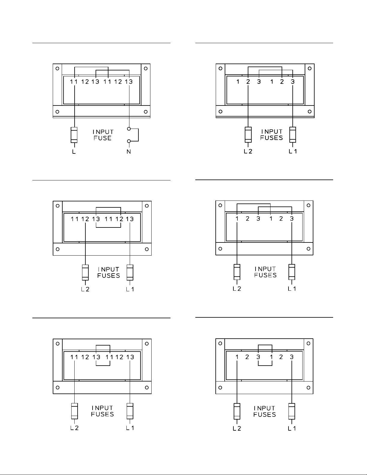
FIGURE 1: SINGLE PHASE INPUT
L2
L2L2L2L1L1L1BRN
BLK
BLK
BLK
BLK
BRN
BRN
BRN
BRNL1L1
BLK
BLK
BRNL1L2
L2
WARNING: IMPROPER WIRE AND JUMPER CONNECTION MAY CAUSE SEVERE DAMAGE TO THE
CHARGER AND BATTERY
120 VAC CONFIGURATION (120/208/240V INPUT)
208 VAC CONFIGURATION (208/240/480V INPUT)
208 VAC CONFIGURATION (120/208/240V INPUT)
240 VAC CONFIGURATION (120/208/240V INPUT)
240 VAC CONFIGURATION (208/240/480V INPUT)
480 VAC CONFIGURATION (208/240/480V INPUT)
Instr. 4770-65-95005-00 Page
4
Page 9
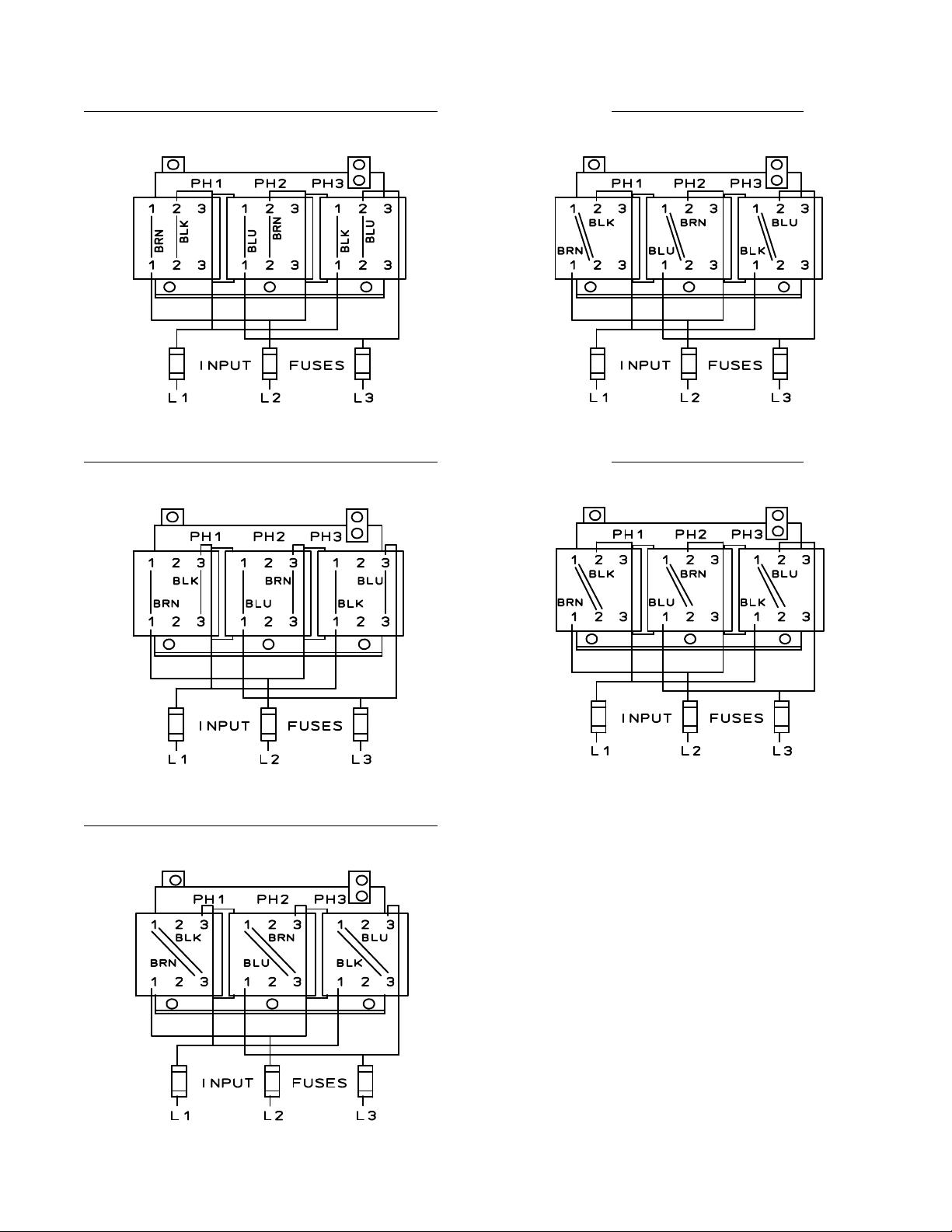
FIGURE 2: THREE PHASE INPUT
L3
L2
L2
L3
L3L3L3
WARNING: IMPROPER WIRE AND JUMPER CONNECTION MAY CAUSE SEVERE DAMAGE TO THE
CHARGER AND BATTERY
208VAC CONFIGURATION (208/240/480V INPUT)
380VAC CONFIGURATION
L2
L1
L2
L1
L3
240VAC CONFIGURATION (208/240/480V INPUT)
L2
L1
L2
L1
L2
L2
L1
L3
L2
L1
415VAC CONFIGURATION
L1
L3
L2
L1
L3
480VAC CONFIGURATION (208/240/480V INPUT)
L1
L3
Instr. 4770-65-95005-00 Page
L1
5
Page 10
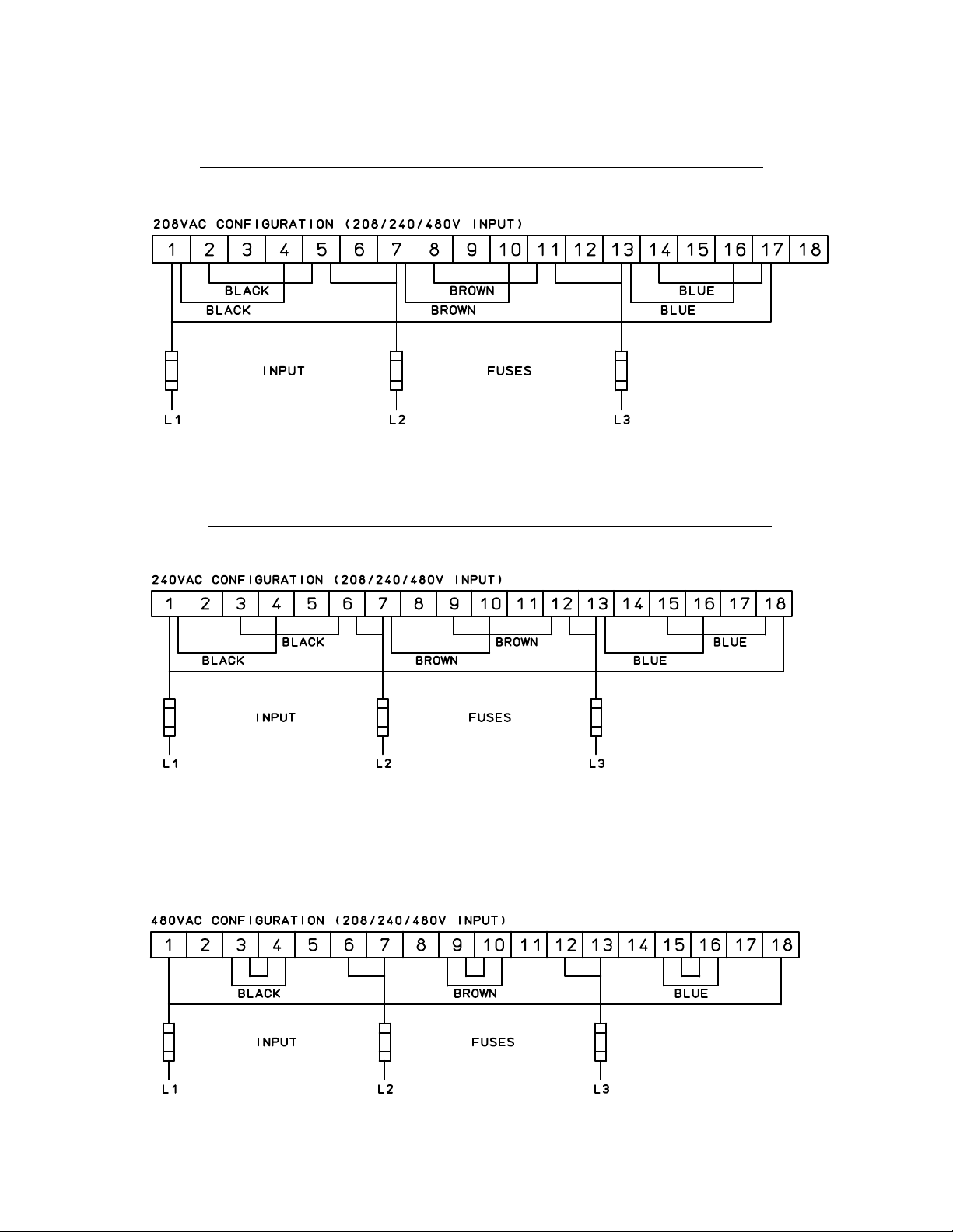
FIGURE 3: THREE PHASE INPUT
WARNING: IMPROPER WIRE AND JUMPER CONNECTION MAY CAUSE SEVERE DAMAGE TO THE
CHARGER AND BATTERY
208VAC CONFIGURATION (208/240/480V INPUT) (SCR100-XX-YYYT1Z ONLY)
L1
L1
L2
L2
L3
L3
240VAC CONFIGURATION (208/240/480V INPUT) (SCR100-XX-YYYT1Z ONLY)
L2 L3
L2
L3
L1
L1
480VAC CONFIGURATION (208/240/480V INPUT) (SCR100-XX-YYYT1Z ONLY)
L1
Instr. 4770-65-95005-00 Page
L2 L3
L3L2
6
L1
Page 11
5.3 AC VOLTAGE CONNECTIONS
6.0 DC OUTPUT
To connect the input AC voltage, route the AC conduit
through the knockout hole provided. Continue the AC
wiring to fuseholder terminals L1 (N) and L2 (L) (single
phase input) or L1, L2, and L3 (three phase input),
ensuring that the AC source phases match the phase
rotation on the AC input. For proper connection, torque
the screws to approximately 25 inch-pounds.
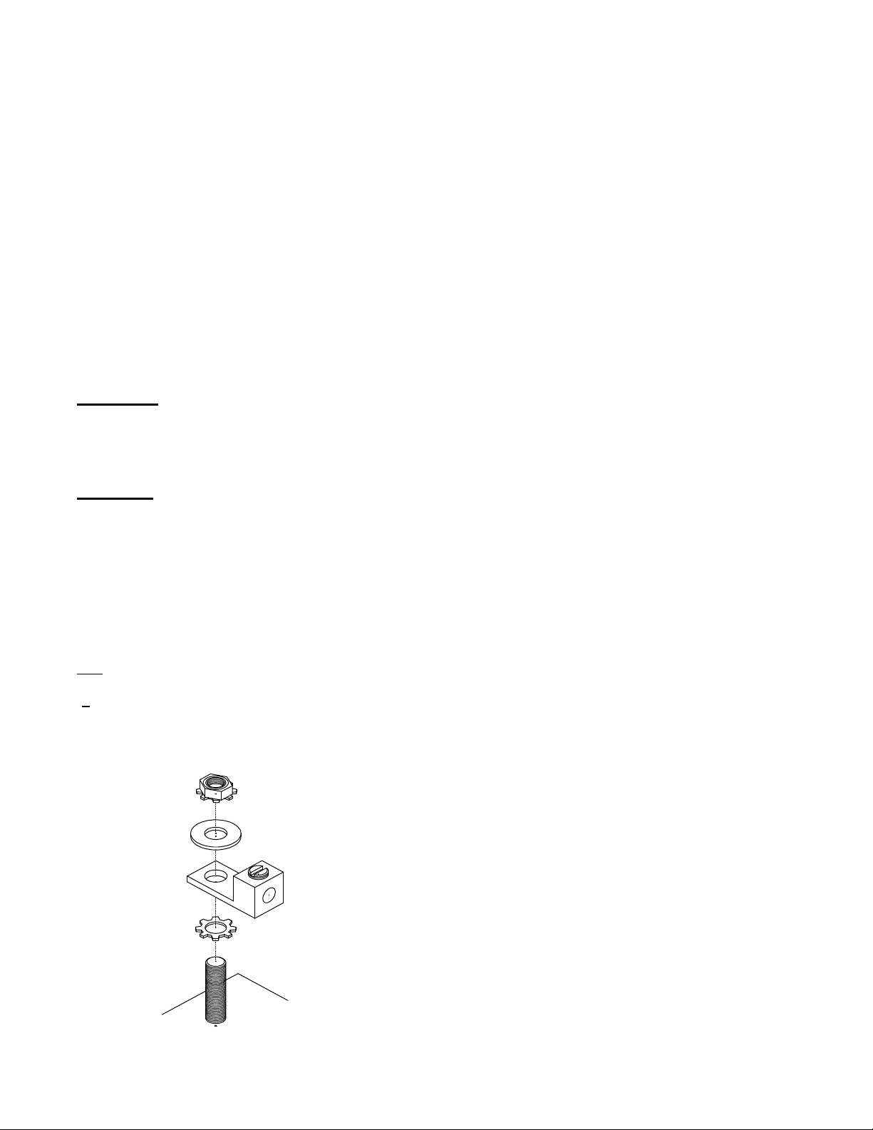
5.4 GROUND CONNECTION
It is a requirement to ground the chassis while the
charger is connected to AC power. The charger comes
with a ground lug attached to the stud, clearly marked on
the chassis. To ensure good continuity keep the contact
area clean. The stud is designed for a 3/16” hardware.
See gounding method shown below (Figure 4.).
WARNING: DO NOT OPERATE THE UNIT
WITHOUT PROPER GROUNDING. IMPROPER
GROUNDING CAN RESULT IN THE RISK OF AN
ELECTRIC SHOCK.
CAUTION: USE MINIMUM 75°C WIRING. FOR
SUPPLY CONNECTIONS, GROUND CHARGER
PROPERLY USING GROUNDING STUD (GND)
PROVIDED. USE COPPER-CLAD ALUMINUM,
ALUMINUM OR COPPER CONDUCTORS ONLY.
The DC charging cable has a commonly used battery
plug or receptacle. The polarity of the charger plug must
be the same as the battery connector. The BLACK DC
cable must be connected to the battery negative (-), and
the RED DC cable must be connected to the battery
positive (+). The charger will not operate in a reversed
polarity condition.
The DC output fuse is a "fast-acting" fuse used to
protect the power semiconductors of a charger.
NOTE: Use only identical replacement fuses obtainable
from your GNB service representative
After electrical connection is completed, the charger is
ready for operation.
NOTE: The following applies to three phase chargers
only: if the charger indicates “FAC” or “F3” upon startup, it means that there is a low or high AC voltage
(+35%) or AC phase missing. Refer to the
Troubleshooting section for more details.
FIGURE 4: GROUNDING METHOD
Instr. 4770-65-95005-00 Page
7
Page 12

7.0 APPLICATION
The charger will automatically charge a battery per the
Ah rating set at the factory. The charger can be re-set
for anywhere between 65% to 200% of the nameplate
Ah rating. Ensure that battery and charger are matched.
Keep in mind if the charger is set for more than 100% of
Ah of the charger rating the charging time will increase
proportionately (up to 16 hours). For battery sizes not
listed, contact your local GNB service representative.
7.1 FAULT AND DISPLAY CODES
Refer to Appendix A (on page 20) for a complete list of
codes.
7.2 OPTIONS
7.2.1 JIC SWITCH ASSEMBLY
All SCR100 battery chargers can come with a factory
installed fused JIC switch assembly option for extra
protection of the operator. In the "OFF" position, the door
can be opened but only AC power at the input of the
switch is present while everything downstream is dead.
In the "ON" position, AC power is supplied to the charger
but the door cannot be opened. See applicable drawing
4770-65-73041-05, 4770-65-73041-15 or 4770-6573041-17 for electrical schematic (Appendix B, pages
21-31). NOTE: Only HRCI-R type fuses (ECSR or
equivalent) with the notched ferrule at one end can be
used. A JIC type charger can only be factory installed
and is available in a “B”, “C” or “D” size cabinet.
convenient location for use. When installing the push
buttons ensure that there are no corrosive fumes
deteriorating the contacts. The Remote Stop / Equalize
option is available for “Z” model chargers “B” and “C”
cabinets, 6 – 36 cells only. For non “Z” models contact
your local GNB service representative.
7.2.2 BATTERY WATERING OPERATION
AND END OF CHARGE
The SCR100 battery charger has an available watering
control and end of charge option, in the form of a relay
contact at terminals TB10-1 to TB10-2 (supplied for
customer connection). The relay closes thirty minutes
after the charger reaches gassing voltage. It remains
closed for approximately ten minutes.
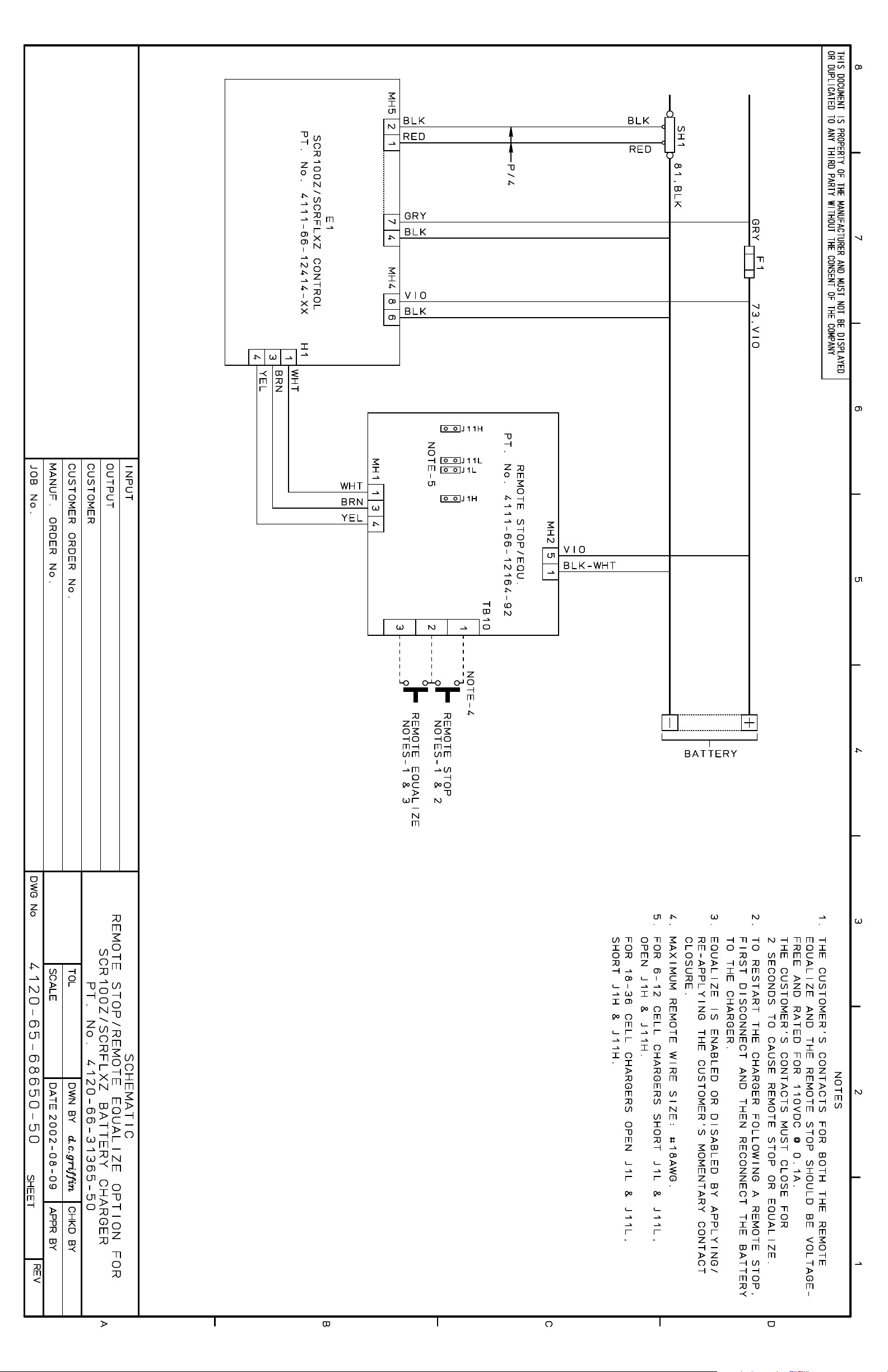
NOTE:These options require different control cards per
drawing 4120-65-68650-05 (see Appendix B, pages 21-
31).
RELAY CONTACT RATINGS:
- AC: 125V 0.6A 1.0PF maximum
- DC: 30V 2A resistive maximum
7.2.3 REMOTE STOP / EQUALIZE
The SCR100 battery charger can come with a factory
installed Remote Stop / Equalize assembly option (partnumber V16-31365-50) in case the charger is out of
reach for the operator. The end user will have to install
two separate push buttons to the appropriate terminals
on the Remote Stop / Equalize circuit board (see
schematic 4120-66-68650-50) and locate them to a
Instr. 4770-65-95005-00 Page
8
Page 13

TABLE 2 – SINGLE PHASE TECHNICAL DATA
9
STANDARD MODEL
SCR100-XX-XXXX-S1Z
SCR100-06-260S1Z AMPS 12 7 6 3 A 76 34.5
SCR100-06-475S1Z AMPS 19 11 9.5 5 A 120 54.4
(50 Hz) AMPS X X 9.5 X A 130 59.1
SCR100-06-600S1Z AMPS 26 15 14 7 B 190 86.2
(50 Hz) AMPS X X 13.5 X B 205 93.2
SCR100-06-865S1Z AMPS C.F. 20 18 9 B 255 116
SCR100-06-965S1Z AMPS C.F. 23 20 10 B 295 134
SCR100-09-475S1Z AMPS 26 15 14 6.5 B 160 72.5
SCR100-09-600S1Z AMPS C.F. 19 16 8 B 210 95
SCR100-09-865S1Z AMPS C.F. 27 23.5 12 B 260 118
SCR100-09-965S1Z AMPS C.F. 30 26 13 B 300 136
SCR100-12-260S1Z AMPS 18.5 10.5 9 5 A 120 54.4
(50 Hz) AMPS X X 9 X A 130 59.1
SCR100-12-475S1Z AMPS C.F. 19.5 17 8.5 B 200 90.7
(50 Hz) AMPS X X 17 X B 212 96.4
SCR100-12-600S1Z AMPS C.F. 25.5 22 11 B 225 102
(50 Hz) AMPS X X 22 X B 235 107
SCR100-12-750S1Z AMPS C.F. 34 29 14.5 B 270 122
SCR100-12-865S1Z AMPS C.F. 34 29 14.5 B 270 122
SCR100-12-965S1Z AMPS C.F. 38 34 17 B 305 138
SCR100-18-260S1Z AMPS C.F. 16 14 7 B 195 88.5
SCR100-18-475S1Z AMPS C.F. 30 26 14 B 240 109
DC AC AMPS @ AC VOLTS CABINET WEIGHT
AMPS 120 208 240 480 TYPE LBS KGS
40
74
74
93
93
134
150
74
93
134
150
40
40
74
74
93
93
116
134
150
40
74
FUSE 15 10 8 4
FUSE 25 15 12 7
FUSE - - 12 -
FUSE 35 20 20 10
FUSE - - 20 -
FUSE - 25 25 12
FUSE - 30 25 15
FUSE 35 20 20 10
FUSE - 25 20 10
FUSE - 35 30 15
FUSE - 40 35 20
FUSE 25 15 12 7
FUSE
FUSE - 25 25 12
FUSE
FUSE - 35 30 15
FUSE - - 30 -
FUSE - 45 40 20
FUSE - 45 40 20
FUSE - 50 45 25
FUSE - 20 20 10
FUSE - 40 35 20
-
-
- 12 -
- 25 -
Instr. 4770-65-95005-00 Page
Page 14

TABLE 2 – SINGLE PHASE TECHNICAL DATA
10
STANDARD MODEL
SCR100-XX-XXXX-S1Z
SCR100-18-600S1Z
SCR100-18-750S1Z
SCR100-18-865S1Z
(50 Hz)
SCR100-24-260S1Z
SCR100-24-475S1Z
(50 Hz)
SCR100-24-600S1Z
(50 Hz)
NOTE: C.F.: CONTACT FACTORY; X: NOT AVAILABLE; -: DATA NOT AVAILABLE
DC AC AMPS @ AC VOLTS
AMPS 120 208 240 480 TYPE LBS KGS
93
116
134
134
40
74
74
93
93
AMPS
FUSE
AMPS
FUSE
AMPS
FUSE
AMPS
FUSE
AMPS
FUSE
AMPS
FUSE
AMPS
FUSE
AMPS
FUSE
AMPS
FUSE
C.F. 36.5 31.5 16 B 260 118
- 50
C.F.
-
C.F.
-
X X
-
C.F.
- 30
C.F.
-
X X
-
C.F.
X X
X X
48
60
48
60
-
22
39
50
48
60
40 20
44 22
60 30
44 22
60 30
44 X
60 19 10
25 15
33.5 17
45 25
33.5 X
45 41 21
60
41
60
30
X
X
WEIGHT
CABINET
C 260 118
C 325 147
C 340 155
B 300 135
C 315 143
C 340 155
C 380 172
C 400 182
Instr. 4770-65-95005-00 Page
Page 15

TABLE 3 – THREE PHASE TECHNICAL DATA
AC AMPS @ AC VOLTS
STANDARD MODEL DC 60Hz 50Hz CABINET WEIGHT
SCR100-XX-XXXX-T1Z AMPS 208 240 480 380 415 TYPE LBS KGS
SCR100-06-475T1Z
SCR100-06-600T1Z
SCR100-06-865T1Z
SCR100-06-965T1Z
SCR100-06-1050T1Z
SCR100-06-1450T1Z
SCR100-09-600T1Z
SCR100-12-475T1Z
SCR100-12-600T1Z
SCR100-12-750T1Z
SCR100-12-865T1Z
SCR100-12-965T1Z
SCR100-12-1050T1Z
SCR100-12-1200T1Z
SCR100-12-1450T1Z
SCR100-18-260T1Z
SCR100-18-475T1Z
SCR100-18-750T1Z
SCR100-18-865T1Z
SCR100-18-965T1Z
74
93
116
134
150
163
186
225
93
74
93
116
134
150
163
186
225
40
74
93
116
134
150
AMPS
FUSE
AMPS
FUSE
AMPS
FUSE
AMPS
FUSE
AMPS
FUSE
AMPS
FUSE
AMPS
FUSE
AMPS
FUSE
AMPS
FUSE
AMPS
FUSE
AMPS
FUSE
AMPS
FUSE
AMPS
FUSE
AMPS
FUSE
AMPS
FUSE
AMPS
FUSE
AMPS
FUSE
AMPS
FUSE
AMPS
FUSE
AMPS
FUSE
AMPS
FUSE
AMPS
FUSE
AMPS
FUSE
5 4.5 2.2
C.F. C.F.
B 170 77.1
7 6 3 - 7 6 3.5
10 8 5
9 8 4
C.F.
C.F. C.F.
3.5 B 190 86.2
-
5
B 220 99.8SCR100-06-750T1Z
12 12 6 - 10 9 5
C.F. C.F.
B 220 99.8
15 12 7 - 11 10 5
C.F. C.F.
B 235 107
15 15 7 - 12 11 5.5
C.F. C.F.
B 245 111
15 15 8 - -
12.7 11 5
20 15 7
15 14 7
C.F. C.F.
- -
C.F. C.F.
C 260 118SCR100-06-1200T1Z
C 290 132
20 20 10 - 12 10 5
C.F. C.F.
B 220 99.8
15 15 7 - -
9 8 4 5.5 5.0 B 215 97.6
12 12 6 8 7
11.5 10 5 7 7 B 220 100
15 15 7 10 10
15 14 7 9.2 9 B / C* 250 113.5
20 20 10 12 12
16 14 7 10 9 B 255 116
20 20 10 15 12
21 18 9
C.F. C.F.
C 260 118
30 25 12 - 22 19 9.5 12
C.F.
C 270 122
30 25 12 15
26 22 11
C.F. C.F.
C 298 135
35 30 15 - 30 26 14
C.F. C.F.
C 310 141
40 35 20 - -
9 8 4
C.F. C.F.
B 215 98
12 10 6 - 14 11 5.5
20 15 8
16 14 7
20 20 10
C.F.
-
C.F.
-
8 B 255 116
12
10 B / C* 300 136SCR100-18-600T1Z
15
20 18 9.0 16 15 B / C* 310 141
30 25 12 20 20
24 21 10.5 16 15 C 325 148
35 30 15 20 20
26 22 11 18 17 C 340 155
35 30 15 25 25
Instr. 4770-65-95005-00 Page
11
Page 16

TABLE 3 – THREE PHASE TECHNICAL DATA
AC AMPS @ AC VOLTS
STANDARD MODEL DC 60Hz 50Hz CABINET WEIGHT
SCR100-XX-XXXX-T1Z AMPS 208 240 480 380 415 TYPE LBS KGS
SCR100-18-1050T1Z
SCR100-18-1200T1Z
SCR100-18-1700T1Z
SCR100-24-475T1Z
SCR100-24-600T1Z
SCR100-24-865T1Z
SCR100-24-965T1Z
SCR100-24-1050T1Z
SCR100-24-1200T1Z
SCR100-24-1450T1Z
SCR100-24-1700T1Z
SCR100-36-475T1Z
SCR100-36-600T1Z
SCR100-36-750T1Z
SCR100-36-865-T1Z
SCR100-36-965-T1Z
SCR100-36-1450-T1Z
SCR100-40-1200-T1Z
SCR100-48-600-T1Z
SCR100-48-865-T1Z
163
186
225
264
74
93
116
134
150
163
186
225
264
74
93
116
134
150
225
74
186
93
134
AMPS
FUSE
AMPS
FUSE
AMPS
FUSE
AMPS
FUSE
AMPS
FUSE
AMPS
FUSE
AMPS
FUSE
AMPS
FUSE
AMPS
FUSE
AMPS
FUSE
AMPS
FUSE
AMPS
FUSE
AMPS
FUSE
AMPS
FUSE
AMPS
FUSE
AMPS
FUSE
AMPS
FUSE
AMPS
FUSE
AMPS
FUSE
AMPS
FUSE
AMPS
FUSE
AMPS
FUSE
AMPS
FUSE
28 24 12 19 17.5 C 380 163
40 35 15 25 25
37 32 16 26
C.F.
C 410 186
50 45 20 35 -
47.5 41 21 26 27 C 450 204SCR100-18-1450T1Z
60 60 30 35 35
48 44 22
C.F. C.F.
D 550 250
60 60 30 - 17 15 7.5
C.F.
10 B / C* 290 132
25 20 10 - 15
21 18 9.5 15 12 C 320 145
30 25 12 20 15
28 24 12 18 15 C 345 157SCR100-24-750T1Z
40 35 15 25 20
31 27 14 18 17.6 C 380 173
45 40 20 25 25
40 36 18
C.F.
20 C 400 182
60 50 25 - 30
44 38 18.5 24 22 C 425 193
60 50 25 35 30
C.F. 46 23 28 C.F. C 440 200
-
60 30 40
-
C.F. C.F. 27 27 22 C 490 222
- -
C.F. C.F.
- -
34 29 14.5
45 40 20
35 35 30
31 31 25 D 525 239
40 40 35
C.F. C.F.
C 330 150
- -
41 35 18 21 20.5 C 420 190
60 50 25 35 30
46 40 20
60 60 30
C.F.
-
46.5 23
60 30
C.F. C.F.
- -
27
40
C.F.
-
C.F.
-
C.F.
-
27 C 460 209
35
27 C 480 218
35
29.4 C 500 227
40
C.F. C.F. 37 C.F. 42 D 550 250
- -
39 34 17
50 45 25
C.F. C.F.
- -
48 42 21
60 60 30
50
33
45
-
C.F.
-
C.F. C.F.
- -
C.F. C.F.
- -
C.F. C.F. C.F. C.F. C.F.
60
19.5 C 450 204SCR100-40-475-T1Z
25
D 500 227
D 550 250
D 600 272
- - - - -
NOTE: C.F.: CONTACT FACTORY; X: NOT AVAILABLE -: DATA NOT AVAILABLE; *:50Hz MODELS ARE IN A “C” CABINET
Instr. 4770-65-95005-00 Page
12
Page 17

13
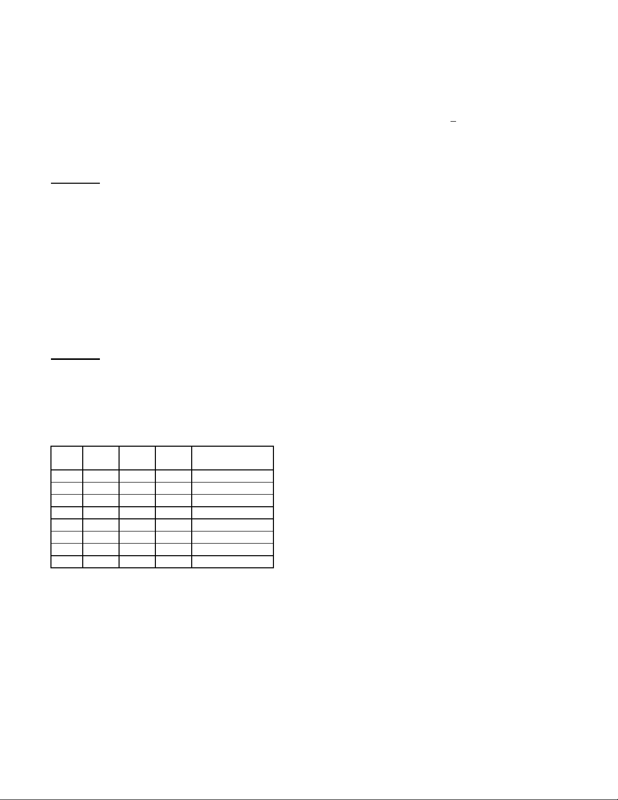
8.0 CABINET OUTLINE/DIMENSIONS FOR –Z MODEL CHARGERS ONLY
CABINET DIM. A DIM. B DIM. C
A 15.10” 20.65” 12.75”
B 22.70” 26.65” 22.25”
C 32.10” 26.65” 22.25”
D 24.30” 42.00” 23.65”
D (Mining) 24.30” 42.00” 23.65”
E (Mining) 24.30” 59.00” 31.50”
NOTE: Mining chargers are equipped with a drip cap and four lifting eyebolts for sling lifting. Add an
additional 5.000” to the height. (DIM.B)
Instr. 4770-65-95005-00 Page
Page 18

14
9.0 SCR100 STANDARD CHARGER OPERATION
LED DISPLAY DESCRIPTION
(NONE)
PLUG IN BATTERY TO COMMENCE CHARGING
OFF/Fld*
OFF/CHP*
DELAY (Orange), dEL, then
delay time remaining in Hours.
minutes
OFF
dEL
time
CHARGING (Orange)
XXX*
(DISPLAY OF FINISH RATE CURRENT)
CHARGING (Orange)
XXX
(DISPLAY OF CHARGE CURRENT)
80% CHARGED (Yellow)
XXX
(DISPLAY OF FINISH RATE CURRENT)
OPC
FAULT (Red)
OFF
CHARGER SET FOR FLOODED BATTERIES.
CHARGER SET FOR SEALED CHAMPION®
BATTERIES.
DELAY MODE, PRESS “START” BUTTON TO
OVERRIDE. (Section 9.1.1, page 15)
SMART START (Section 9.1.2, page 15)
HIGH RATE CHARGING
FINISH RATE CHARGING
OPPORTUNITY CHARGING CYCLE
WHEN CHARGER IS IN OPC MODE IT WILL ALWAYS
INDICATE OPC IN ADDITION TO STANDARD INDICATION.
CHARGE CYCLE WAS INTERRUPTED BY
PRESSING “STOP” BUTTON BEFORE
UNPLUGGING THE BATTERY
FAULT (Red)
CHARGE COMPLETE (Green)
flashing, remaining cooldown time
displayed in Hours.minutes
OFF/
XXX
OFF
CoL*
FAULT CONDITION EXISTS. UNPLUG THE
BATTERY AND GO TO APPENDIX A FOR
DETAILS. OTHER INDICATION DISPLAYED (i.e.
FAC, Fdc, Lo, HI, etc.)
CHARGING IS COMPLETE. ONCE COOLDOWN
TIME IS FINISHED, UNPLUG THE BATTERY.
time
CHARGE COMPLETE (Green)
on (not flashing), remaining
refreshing time displayed in
0
Hours. minutes
OFF
rFr*
BATTERY CAN BE UNPLUGGED AND USED.
time
EQUALIZE (Orange)
XXX
(DISPLAY OF CHARGE CURRENT)
∗∗
THESE DISPLAYS OR OPTIONS ARE AVAILABLE ONLY ON Z MODEL CHARGERS OR REPLACEMENT BOARDS
PRESS “EQUALIZE” BUTTON TO EQUALIZE THE
BATTERY. PRESS AGAIN TO CANCEL.
Instr. 4770-65-95005-00 Page
Page 19
9.1 SCR100 CHARGER FUNCTIONAL
DESCRIPTION
9.1.2.1 SMART START STAGE
This section gives a brief description of each LED,
pushbutton, and the delay function on the SCR100 type
charger front control panel.
9.1.1 DELAY STAGE
9.1.1.1 DELAY CIRCUIT
CAUTION: HAZARDOUS VOLTAGES INSIDE. DO NOT
ATTEMPT TO CHANGE THE SLIDE SWITCHES ON
THE CONTROL CARD UNTIL ALL AC POWER IS
DISCONNECTED FROM THE UNIT AS WELL AS THE
BATTERY IS UNPLUGGED FROM THE CHARGER.
USE PROPER TOOL TO OPEN THE CABINET DOOR.
1. The delay circuit enables the user to set a delay of up
to eight hours between battery plug in and the start of
charge.
2. The delay time must be set prior to charging. This can
be done via the slide switches located on the back of
the charger control card. Refer to Table 5 below for
details.
CAUTION: DO NOT TOUCH THE OTHER SLIDE
SWITCHES ON THE BACK OF THE CONTROL
BOARD. THESE ARE FACTORY SET AND CAN ONLY
BE CHANGED BY A QUALIFIED GNB SERVICE
REPRESENTATIVE.
TABLE 5
SW5 1 2 3 START DELAY
(HOURS)
ON ON ON 0 (DEFAULT)
OFF ON ON 1
ON OFF ON 2
OFF OFF ON 3
ON ON OFF 4
OFF ON OFF 5
ON OFF OFF 6
OFF OFF OFF 8
9.1.1.2 DELAY LED
Smart Start is only available on Z model chargers and
replacement boards.
The charge cycle starts with Finish Rate current. If the
voltage reaches 2.18VPC + 1% (Sealed /Flooded) within
5 minutes, the charger goes to the Refresh Charge
Stage. If it does not reach the above voltage in 5 minutes
the charger will go to the High Rate charging stage.
9.1.2.2 CHARGING LED
This LED indicates that the charger is ON.
9.1.2.3 80 % CHARGED LED
This LED indicates that the battery has reached 80%
charge.
9.1.2.4 CHARGE COMPLETE LED
When this LED is continuously lit it indicates that the
charging cycle is complete. The battery may now be
safely disconnected. In the event this LED is flashing, it
indicates that cooldown is in progress.
9.1.2.5 FAULT LED
This LED is associated with any fault that is described in
Appendix A SCR100 BATTERY CHARGERS. LIST
OF DISPLAY CODES (page 20). It indicates that there
is a problem prior to or during the battery charging
operation.
9.1.3 DISPLAY
The display shows the charging current to the battery
during the charging process. The display will show
additional messages as the charging is progressing or a
fault occurs.
9.1.4 STOP PUSHBUTTON
This pushbutton will STOP the charge cycle. The battery
can then be safely unplugged. The red fault LED will light
to indicate that the charge cycle was interrupted.
This LED indicates that the charger is in the delay mode
and charging will not start until the delay time has
elapsed. A flashing Delay LED indicates that the delay is
in progress.
9.1.1.3 START DELAY OVERRIDE
This pushbutton will override the charger delay mode and
charging will start immediately.
9.1.2 CHARGING
Instr. 4770-65-95005-00 Page
9.1.5 BATTERY COOLDOWN OPERATION
STAGE
Cool Down step is only available on Z model chargers
and replacement boards.
A cooldown period is incorporated in the charge cycle.
This stage serves to cool down the battery before being
placed back in service. During this time the display will
alternate between “COL” and time remaining in this stage.
If the battery is unplugged during cooldown the display will
show “FCD”. During the cooldown period, Equalize can
be activated by pressing the Equalize button. If this
15
Page 20

occures, cooldown will not start until after Equalize
charging is complete.
9.1.6 REFRESH CHARGE STAGE
If the AC power fails during a charge cycle the charger will
resume operation in progress as soon as the AC power is
restored.
Refresh Charge is only available on Z model chargers
and replacement boards.
If a battey is left connected to the charger after cooldown,
the charger will go into a refresh charge mode. This
means that 24 hours after a charging was finished the
battery will get a refresh charging for 10 minutes every 24
hours, at finish rate current.
9.1.7 EQUALIZE STAGE
9.1.7.1 EQUALIZE PUSHBUTTON
This pushbutton when pressed will extend the charge
cycle by 3.5 hours in the equalize mode after the finish
rate time has expired. If pressed a second time, it will
cancel the equalize charge mode.
CAUTION: DO NOT EQUALIZE MORE OFTEN THAN
REQUIRED BY THE CONDITION OF THE BATTERY,
AS SPECIFIED IN THE BATTERY MAINTENANCE
INSTRUCTIONS. EXCESSIVE EQUALIZING MAY
DAMAGE THE BATTERY.
9.1.7.2 EQUALIZE LED
13.0 MAINTENANCE
The charger requires minimum maintenance. ENSURE
THE CHASSIS IS SECURELY GROUNDED per the
local/federal Electrical Code. Do not allow excessive dust
to accumulate on the components inside. Blow out with
clean compressed air when necessary.
The AC input and DC output of the charger are fused and
should these fuses fail, the cause of the failure must be
determined and corrected before the fuse(s) is (are)
replaced. Never replace the fuse(s) with one of a higher
capacity than the one originally fitted. (see Tables 2 and 3
pages 9-12).
This LED indicates that the equalize mode has been
selected.
10.0 OPPORTUNITY CHARGING
The charger is equipped with a separate profile for
applications that utilize opportunity charging for
Champion® Batteries.
Within 5 seconds the charger will start charging in hirate
current until the gassing voltage is reached. At this point
the charging will stop until the battery voltage drops to a
specified (user programmed) level. The charger will
operate at finish rate current until the battery reaches a
second specified (also user programmed) voltage. The
charger will continue through this cycle until the battery is
disconnected.
11.0 CHARGE TIME
The amount of time a battery charges will vary depending
on the depth of discharge (DOD). Once the battery has
reached 80% charge, the cycle will be terminated 3.5
hours after finish rate (in case of an 8 hour charge time)
or less if terminated by dv/dt. Normal charge cycles will
average about 8 hours total.
12.0 AC POWER FAILURE
Instr. 4770-65-95005-00 Page
16
Page 21

14.0 SCR100 TROUBLESHOOTING
1.Symptom =>
Charger connected to low AC voltage. Verify AC voltage per nameplate of the charger
1.1
Charger connected to high AC voltage. Verify AC voltage per nameplate of the charger
1.2
2. Symptom =>
Charger connected to low / high AC voltage. Verify AC voltage per nameplate of the charger
2.1
AC power partially missing. Verify AC voltage at all primary windings of
2.2
Failure of one or more of charger’s power fuses. Consult GNB technician.
2.3
Phase rotation. (Only if F3 is showing) Verify phase sequence of input AC source.
2.4
NO DISPLAY INDICATION AFTER CONNECTION OF AC POWER
Possible Cause Action
and electrician’s tag.
Verify connection of primary windings of power
transformer and AC fuses of charger per
connected AC voltage and electrician’s tag.
and electrician’s tag.
Verify connection of primary windings of power
transformer and AC fuses of charger per
connected AC voltage and electrician’s tag.
Check AC fuses of charger and replace if needed.
Check fuse F2 of Control Card. If this fuse is blown,
replace Control Card.
DISPLAY INDICATES FAC OR F3 AFTER CONNECTION OF AC POWER
Possible Cause Action
and electrician’s tag.
Verify connection of primary windings of power
transformer and AC fuses of charger per
connected AC voltage and electrician’s tag.
power transformer and AC fuses of charger per
nameplate of the charger and electrician’s tag.
Replace fault fuse. Verify input AC voltage and
output High Rate current.
Ensure that it follows the sequence indicated at
the charger’s input.
3. Symptom =>
3.1
Previous charge cycle was interrupted by DC
cable disconnection.
Shorted or leaky SCRs/diodes. Disconnect battery and AC power.
3.2
DISPLAY INDICATES FCA BEFORE CONNECTION OF BATTERY
Possible Cause Action
Do not interrupt charge by DC cable
disconnection. Use pushbutton Stop for this
purpose.
Connect next battery – charger will start
automatically.
Consult GNB technician.
Instr. 4770-65-95005-00 Page 17
Page 22
4. Symptom =>
4.1
Previous charge cycle was interrupted during
Cool Down.
DISPLAY INDICATES FCD BEFORE CONNECTION OF BATTERY
Possible Cause Action
Do not interrupt charge cycle until LED End is
continuously on.
Connect next battery – charger will start
automatically.
5. Symptom =>
5.1
Charge cycle was interrupted during charge by
DC cable disconnection with slow / bouncing
disconnection of DC plug.
Charge cycle was interrupted by DC cable
5.2
disconnection during charge. Additionally, a
battery was connected back before charger
displayed FCA.
Indication FdC and FAULT LED is on.
Charger’s DC fuse blown.
5.3
Indication FdC and FAULT LED is on.
DISPLAY INDICATES FDC BEFORE CONNECTION OF BATTERY.
Possible Cause Action
Do not interrupt charge by DC cable
disconnection. Use pushbutton Stop for this
purpose. Disconnection of DC cable during
charge is not safe because it produces
electrical arc.
If DC cable disconnection is used, disconnect
cable as fast as possible; never connect battery
before indication FCA appears at display (takes
about 2 s after disconnection of DC cable).
Disconnect battery and AC power for 5 sec.
Return AC power and then connect battery.
See above
Disconnect battery and AC power.
Consult GNB technician.
6. Symptom =>
6.1
Connection between charger and battery open. Repair or clean battery lugs.
6.2
Battery with wrong number of cells connected to
a charger.
Indication LO/rEJ or HI/rEJ and FAULT LED is
on.
6.3
Battery voltage too low.
Indication LO/rEJ and FAULT LED is on.
6.4
A charger operates at Delay.
Indication dEL/Remaining Delay Time, LED
Delay is on.
6.5
Control Card failure.
Indication FFF.
CHARGING LED DOES NOT LIGHT ON AFTER BATTERY CONNECTION
Possible Cause Action
Repair and/or change charger and /or battery
DC cables and contacts of DC connectors.
Replace with correct battery.
Consult GNB technician.
Wait till end of Delay or press pushbutton Start.
Consult GNB technician.
Instr. 4770-65-95005-00 Page 18
Page 23
7. Symptom =>
7.1
Battery failed to reach gassing voltage. Consult GNB technician.
7.2
Battery failed to reach End Voltage (Stage 3 of
OPC).
DISPLAY INDICATES FCC OR F2 AT THE END OF CHARGE CYCLE
Possible Cause Action
Check matching of charger and battery: Ah,
type.
Consult GNB technician.
Check matching of charger and battery: Ah,
type, etc.
8. Symptom =>
Complete or partial loss of AC power. Wait until AC returns: charger will automatically
8.1
Failure of one or more of charger’s power fuses. Consult GNB technician.
8.2
Failure of Control Card. Consult GNB technician.
8.3
9. Symptom =>
Pushbutton Stop interrupted charge cycle. Use pushbutton Stop only when you want
9.1
DISPLAY INDICATES FAC OR F3 DURING CHARGE CYCLE
Possible Cause Action
complete charge cycle.
If needed, battery may be disconnected during
AC failure.
Replace fault fuse. Verify input AC voltage and
output High Rate current.
Verify input AC voltage. Replace fault Control
Card.
DISPLAY INDICATES OFF (ONLY) AND FAULT LED IS ON
Possible Cause Action
interrupt charge cycle or disconnect battery.
Charger will start automatically after
connection of next battery.
Instr. 4770-65-95005-00 Page 19
Page 24
APPENDIX A: SCR100 BATTERY CHARGERS. LIST OF DISPLAY INDICATIONS.
Indication Abbreviation Interpretation
1.00
2.00
3.00
4.00
5.00
6.00
8.00
CHP CHamPion
COL COoL Down
dEL dELay
End End
FAC or F3 Failure of AC power
FCA Failure of DC CAble
FCC
Or
F2
FCd Failure of Cool down
1 hour delay set Delay before charge starts
2 hour delay set Delay before charge starts
3 hour delay set Delay before charge starts
4 hour delay set Delay before charge starts
5 hour delay set Delay before charge starts
6 hour delay set Delay before charge starts
8 hour delay set Delay before charge starts
disconnection
Failure of Charge Cycle
Charger set to sealed Champion®batteries
Charger operates at Cool Down Stage
Delay set or Charger operates at Delay Stage
Charge Cycle complete
Failure of mains
DC cable disconnected from the battery during the
charge
Battery failed to reach Gassing Voltage (Stage 2)
or
Battery failed to reach End Voltage (Stage 3 of
OPC)
Battery unplugged during Cool Down Stage
FdC Failure of dC Fuse
FFF F… Fatal Failure
FLd FLooded
FOC Failure of Overall
Charge timer
HI HIgh Voltage Rejection
LO LOw Voltage Rejection
OFF OFF
OPC OPportunity Charge
Cycle
rEJ rEJect
rFr reFreshing Stage
Output DC Fuse Failure
Fatal Failure of the charger (Overvoltage or
Overcurrent protection or multifunction of Start /
Stop signal)
Charger set for Flooded batteries
Overall charge cycle timer protection
Battery connected has voltage more than 2.25VPC
Battery connected has voltage less than 1.70VPC
Charger is OFF
Charger set to Opportunity Charge Cycle
Battery connected has voltage too low or too high
Or
Battery failed to reach 1.70VPC after 5 min of
charge
Charger operates at Refreshing Stage
Instr. 4770-65-95005-00 Page 20
Page 25

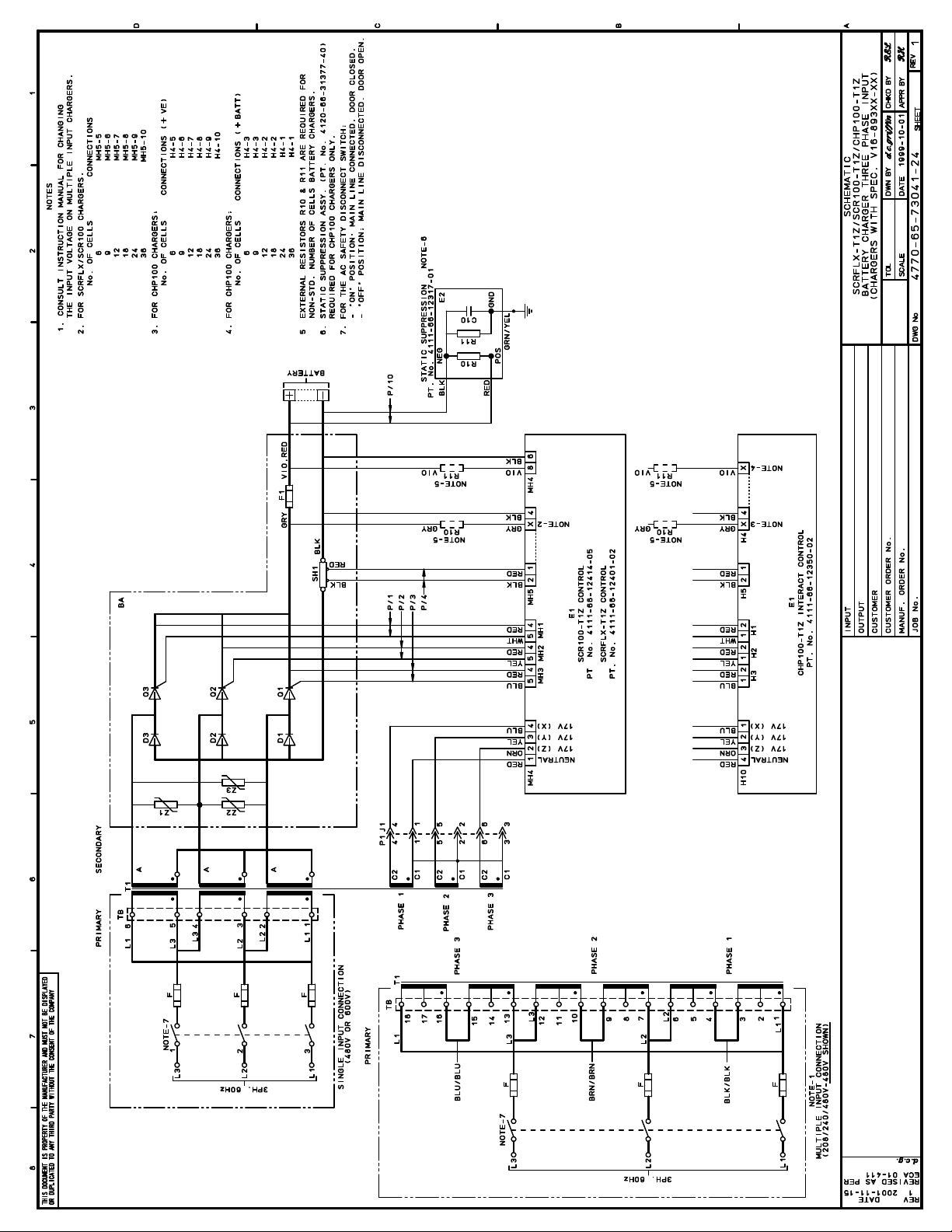
APPENDIX B: ELECTRICAL SCHEMATIC DRAWINGS
Pages 21-31
Instr. 4770-65-95005-00 Page 21
Page 26

Page 27

Page 28

Page 29

Page 30

Page 31

Page 32

Page 33
Page 34

Page 35

Page 36
Page 37

Page 38
SALES • SERVICE • RECYCLING
TOLL FREE 1-888-563-6300
Champion®is a registered trademark of Federal-Mogul Corporation
Exide Technologies
Chloride Motive Power
P.O. Box 1, Salford Road
Over Hulton, Bolton BL5 1DD
United Kingdom
Tel: 44.1204.661.230
Fax: 44.1204.652.100
GNB Industrial Power
Motive Power
8301 Keele Street
Maple, Ontario
Canada L6A 1T2
Tel: 905.669.9326
Fax: 905.669.7688
REV 09/02
GNB Industrial Power
Motive Power
829 Parkview Boulevard
Lombard, IL 60148-3249
U.S.A.
Tel: 877.GNB.INFO
Fax: 630.691.7869
Printed on recycled paper
A
www.gnb.com
 Loading...