

Page 1

Operating Instructions and Safety Precautions for the EHF Series Charger
CHARGE STATUS
INDICATION
mode
2
3
Auto-balance pulse / refresh
5
6
7
Safety
Only a t rained person should operate this equipment. The input
and output voltages used with this equipment may be high enough
to endanger life, so insulated, shrouded connectors must be fitted.
Please read this manual completely and convey instructions to all
personnel concerned. Keep the manual in a s afe and convenient
place.
It is advisable to thoroughly read the information on battery safety
supplied with the battery, prior to charging.
Towards the end of charge, lead acid batteries give off hydrogen
gas, which is explosive if in sufficient concentration, therefore
avoid flames and sparks. Appropriate measures must be taken to
ensure adequate ventilation.
Incorrect use of a charger or maladjustment of its controls can
damage a battery. The equipment has been factory set and does
not require user adjustment.
This product has been designed, manufactured and certified to be
in conformance with UL Standards. Testing has ensured that the
battery and c harger combination conform as a system for use in
Light and Heavy Industrial environments for each respective
product variant. The following notes are for the guidance of the
person installing and using the product.
The charger must be i solated from the input supply and t he
battery, before any of the panels are removed. It is strongly
recommended that a Safety Warning Notice is placed at the input
supply isolator, to warn against inadvertent reconnection of the
mains supply and the isolator is locked in the off position.
DANGER - Risk of electric shock. Do not touch un-insulated
portion of output connector or un-insulated battery terminal.
Installation
Installation must only be carried out by suitably qualified personnel
and in accordance with current local and national wiring
regulations.
The unit should be positioned using lifting equipment, placed under
the base.
Battery leads should not be altered without prior consultation with
service personnel.
The charger should be sited in a cool, dry, well-ventilated location
away from corrosive fumes and humid atmospheres. Ambient
temperature range must be maintained between 32°F - 95°F.
charger must have a minimum clearance overhead of eight
The
inches (8”), ensuring ventilation is not obstructed at the rear intake
and the front exhaust vents.
The charger is for inside use only.
Before installation, check that:
• The charger has not sustained any transit damage.
• The rating is suitable for the intended input supply and ‘lead
acid’ battery to be charged.
• The connector polarity is correct and matches the polarity of
the battery connector.
Input supply
A hand operated lockable isolator should be used in the
installation, to enable the charger to be disconnected from the
supply, for maintenance or repair work. The charger does not
exhibit high in-rush current, therefore type B or C circuit breakers
can be used.
CAUTI
ON - To reduce the risk of fire, use only on circuits provided
with branch circuit protection consistent with the current indicated
on the rating label and i n accordance with the National Electrical
Code, ANSI/NFPA 70 or equivalent.
The circuit breakers rating should be bas ed on the chargers
maximum input current, as stated on the rating label.
Careful consideration must be taken when connecting this charger
to a generator. The generator must be capable of at least four
times the input power requirements of the charger, failure to do so
can result in damage to the charger. The generator should have
load step immunity to prevent undershoot and overshoot with
typical loads. Typically the generator control bandwidth should be
less than 7Hz with good gain and phase margins.
Display and Control
Overview
1. Communications Port
2. High Visibility - Charge Status Indicator
3. Soft-keys (The function of the button will be displayed on the LCD Display)
4. LCD Display
5. Pause Button
Charge Status Indicator
INDICATION
1
4
LCD Symbols
* Optional extra
*Watering system (Shown when enabled, flashing during operation)
Communications port (Shown when active)
Equalise (Shown when enabled, flashing during operation)
Automatic Equalise (Shown when enabled, flashing during operation)
Warning (Shown when a warning is active)
Battery Recovery Mode (Shown when enabled, flashing during operation)
*Air system enabled (Shown when enabled, flashing during operation)
Cycling red
Cycling yellow Second stage / watering
All green Charge complete
Green with cycling red
All flashing red Critical fault
All off Standby / pause / inhibit
Left hand indicator red Power save mode
MODE
Bulk charge / battery recovery
pulse / equalising / cool down
Operation
Before connecting the battery, check that the battery voltage
corresponds to the voltage indicated inside the battery
symbol on the LCD Display. The charger should be
permanently connected to the mains supply.
Standby
With the input supply connected and no battery, the charger will
enter the standby mode. During this mode the charge status
indicator will show indication 6 and the LCD display will show the
following:
Page 2
As a power saving feature the LCD back light will be switched off
after 1 minute of inactivity, the backlight can be turned back on by
briefly pressing any of the buttons. During this time the charge
status indicator will show indication 7.
Charging
When a battery is connected to the charger, charge will start
automatically. The charge status indicator will show indication 1 or
indication 2 (The speed of the rotation indicat es t he state of charge
of the battery, with fast cycling indicat ing a low charge state) and
the LCD Display will show the following:
The bar graph display gives the user an indication of the batteries
present state of charge.
During charge, the user can scroll through the following charge
information, by pressing the
• VPC Voltage per cell
• Ah Total Ampere hours delivered to the battery
• Amps The present output current
• Stage The present charge stage
• Charge Time The total charge time
• Rest Time Time elapsed since charge completed
• Warnings Displays any warnings - Only shown when
applicable
Charge Complete
When charge is complete the charge status indicator will show
indication 3 and the LCD Display will show the following:
or keys.
the cells to the same charge state, this should be performed after
the standard charge has completed.
This mode can be enabled by pressing the = key during the charge
cycle, a second press will clear this function. The equalize function
can not be c leared once it has started and onl y one equalize is
allowed per cycle.
In addition to enabling equalize manually, the equalize feature can
be set to initiate automatically by configuring the automatic
equalize feature in the programming mode. Automatic equalize
may be set to occur every 0 to 250 cycles. Once set the A=
symbol will be shown in the top right corner of the LCD Display.
Once enabled, the charger will perform the equalize function after
the standard charge has been completed.
Battery Recover Mode
If a bat tery is connected to the charger that is below the normal
operating voltage an incorrect battery fault (F07) will be displayed.
However if the battery voltage is between 1 and 1. 5VPC, battery
recover mode is available. This mode employs a special charging
technique to recover batteries that have been left unused for a
long time or have been over discharged.
This mode can be enabl ed by pressing the BRM key when the
fault is displayed. Battery recover mode will then start; once the
battery voltage has been r ecovered to a normal level a standard
charge will be performed.
Cool Down Mode (Profile Dependant)
Cool down mode is activated after the charge has completed and
allows the battery time to ‘cool down’ before its next use. During
this time the battery should remain connected to the charger, but
can be removed if required.
Delayed Start
Note: This function is only available if the network function is OFF
and can only be set without a battery connected.
The delayed start function will delay the start of charge for a s et
time up to 48 hour s in 15 minute increments. The timer begins
count down upon connection to a battery.
During the delay period the charge status indicator will show
indication 6 and the LCD Display will show the following:
If the Auto Balanc e feature is enabled the battery should be left
connected to the charger until required; under these c ondit ions the
battery will receive periods of refreshing charge to maintai n it in the
fully charged condition. During these periods, the charge status
indicator will show indication 4.
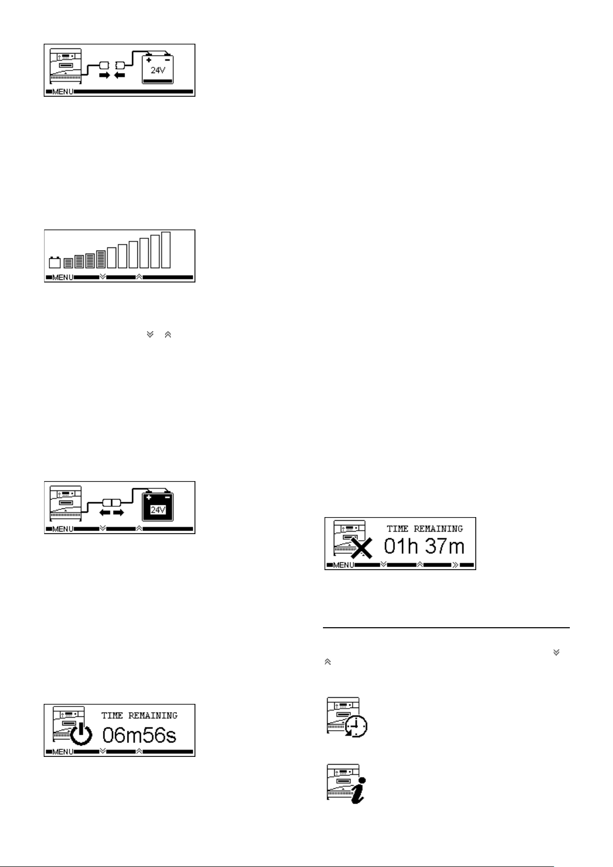
Removing the battery
The battery can only be disconnected when charging current
has stopped flowing. Therefore, the pause button must be
pressed before disconnection. A second press of the paus e key
will clear the pause condition and continue charge (Disabled
during the first 10 seconds of pause).
When the charger is paused the charge status indicator will show
indication 6 and the LCD Display will show the following:
If the pause mode is entered but the battery is not removed within
10 minutes the charge will automatically continue.
Equalize Mode (Profile Dependant)
Periodically, batteries require additional charging to equalize all of
Once the time period has elapsed, charge will start as normal. This
can be overridden by pressing the >> button, for this cycle only.
User menu
A user menu can be ac cessed by pressing the MENU key, the
following options can then be scrolled through by pressing the
keys and then activated by pressing the SELECT key:
Charger History
Cycle Data Total Charge Ah
Cycle Graphs Total Charge Time
Total Initiations
Total Terminations
Charger Information
Charger Type Software Version
Module Part Number Network ID
Module Temperature Network Speed
Serial Number Date Code
Auto Equalisation Watering System
or
Page 3

*Battery History
SALES – SERVICE
Install Date <50% DOD
Inits <80% DOD
Terms >80% DOD
<20% DOD
*Battery Information
Fleet ID Voltage
Capacity S/N
Tag ID ML No
Cell Type
Language
English Dansk
Francais Svenska
Nederlands Espanol
Deutsch
Charger options
Auto Balance AGV
Onboard Safety Disconnect
Stored Equalize BattID
Settings
Set LCD Contrast
Reset Charger
Override / Enable Inhibit
The menu can be exited by pressing the BACK key.
* This menu item can only be selected if the charger has the BattID
option fitted.
Faults / Warnings
If a critical fault occurs during charge the charge status indicator
will show indication 5 and the LCD Display will show the fault code
and description, for example:
Faults permanently stop charge until they are rectified.
If a warning occurs during charge the warning symbol
displayed on t he LCD Display and t he warning code and
description can be ac cessed by scrolling through the charge
information.
Warnings do not affect the charge procedure.
Fault Codes
F06 No output current
F07 * Incorrect battery
F09 * Bulk charge timeout
F10 * Gassing charge timeout
F12 Configuration error
F13 Thermistor fault
F17 * Auto balance timeout
F18 Battery disconnected
F19 Battery disconnected during cooldown
F21 Over current
Warning Codes
F01 * Over discharged battery
F02 * Deep discharged battery
F03 * Sulphated battery
F04 Charger overheating
will be
F05 Mains Failed during charge
F23 Batt ID PCB error
F24 Batt ID Antenna error
F25 Batt ID Tag read error
F26 Batt ID not programmed
F27 ** Slave 1 incorrect correct current
F28 ** Slave 2 incorrect correct current
F29 ** Slave 3 incorrect correct current
F30 ** Slave 1 temperature fault
F31 ** Slave 2 temperature fault
F32 ** Slave 3 temperature fault
* = These faults are usually associated with the battery, check
battery condition.
** = Only applicable on models with dual power modules
Repair
Only suitably qualified personnel should perform repair work
on this equipment.
Use of genuine factory sourced replacement parts is necessary to
ensure UL marking is not invalidated.
Contact your local maintenance facility for assistance or
replacement parts. Always be prepared with the charger type and
serial number prior to placing a call for assistance.
Maintenance
Before carrying out maintenance, isolate the mains supply
and disconnect the battery.
Only suitably qualified personnel should perform
maintenance work on this equipment.
The charger will require little maintenance, but the following
schedule is recommended once a month:
(a) Check the condition of all cables, paying particular
attention to the points where cables may be severely
flexed, i.e. at the entry to charger cabinet, charging plugs
and sockets.
(b) Check condition of charging plugs and sockets for wear
and any evidence of overheating, which could ultimately
lead to charger malfunction.
(c) Check that ventilation is not obstructed.
(d) Ensure that all safety covers and panels are correctly in
place.
RECYCLING
1-888-563-6300
TOLL FREE
www.gnb.com
Page 4

EHF / EHP / EMC CHARGER INSTALATION
EHF - 1PH - Installation Wiring
EHF - 3PH - Installation Wiring
Page 5

EHF / EHP / EMC CHARGER INSTALATION
EHP - 1PH - Installation Wiring
EHP - 3PH - Installation Wiring
Page 6

EHF / EHP / EMC CHARGER INSTALATION
EMC - 1PH - Installation Wiring
EMC - 3PH - Installation Wiring
 Loading...